

Page 1

GE
Intelligent Platforms
Programmable Control Products
VersaMotion
Servo Motors and Amplifiers
User’s Manual, GFK-2480A
October 2012
Page 2

GFL-002
Warnings, Cautions, and Notes
as Used in this Publication
Warning
Warning notices are used in this publication to emphasize that hazardous voltages,
currents, temperatures, or other conditions that could cause personal injury exist in this
equipment or may be associated with its use.
In situations where inattention could cause either personal injury or damage to equipment,
a Warning notice is used.
Caution
Caution notices are used where equipment might be damaged if care is not taken.
Note: Notes merely call attention to information that is especially significant to
understanding and operating the equipment.
This document is based on information available at the time of its publication. While efforts
have been made to be accurate, the information contained herein does not purport to cover all
details or variations in hardware or software, nor to provide for every possible contingency in
connection with installation, operation, or maintenance. Features may be described herein
which are not present in all hardware and software systems. GE Intelligent Platforms assumes
no obligation of notice to holders of this document with respect to changes subsequently made.
GE Intelligent Platforms makes no representation or warranty, expressed, implied, or statutory
with respect to, and assumes no responsibility for the accuracy, completeness, sufficiency, or
usefulness of the information contained herein. No warranties of merchantability or fitness for
purpose shall apply.
* indicates a trademark of GE Intelligent Platforms, Inc. and/or its affiliates. All other
trademarks are the property of their respective owners.
©Copyright 2011 GE Intelligent Platforms, Inc.
All Rights Reserved
Page 3
Contact Information
Online technical support and
GlobalCare
http://support.ge-ip.com
Additional information
http://www.ge-ip.com/
Solution Provider
solutionprovider.ip@ge.com
Online Technical Support
http://support.ge-ip.com
Phone
1-800-433-2682
International Americas Direct Dial
1-780-420-2010 (if toll free 800 option is unavailable)
Technical Support Email
support.ip@ge.com
Customer Care Email
customercare.ip@ge.com
Primary language of support
English
Online Technical Support
http://support.ge-ip.com
Phone
+800-1-433-2682
EMEA Direct Dial
+1-780-401-7717 (if toll free 800 option is unavailable or if
dialing from a mobile telephone)
Technical Support Email
support.emea.ip@ge.com
Customer Care Email
customercare.emea.ip@ge.com
Primary languages of support
English, French, German, Italian, Czech, Spanish
Online Technical Support
http://support.ge-ip.com
Phone
+86-400-820-8208
+86-21-3217-4826 (India, Indonesia, and Pakistan)
Technical Support Email
support.cn.ip@ge.com (China)
support.jp.ip@ge.com (Japan)
support.in.ip@ge.com (remaining Asia customers)
Customer Care Email
customercare.apo.ip@ge.com
customercare.cn.ip@ge.com (China)
If you purchased this product through an Authorized Channel Partner, please contact the seller
directly.
General Contact Information
Technical Support
If you have technical problems that cannot be resolved with the information in this manual, please
contact us by telephone or email, or on the web at http://support.ge-ip.com
Americas
Europe, the Middle East, and Africa
Asia Pacific
iii VersaMotionServo Motors and Amplifiers User’s Manual–October 2012 GFK-2480A
Page 4

Page 5

Contents
Introduction .................................................................................................................... 1-1
1.1 Product Overview ....................................................................................................... 1-3
1.2 Servo Drive and Servo Motor Combinations ............................................................ 1-11
1.3 Servo Drive Control Modes ....................................................................................... 1-12
Unpacking and Installation ........................................................................................... 2-1
2.1 Unpacking and Inspection .......................................................................................... 2-2
2.2 Storage Conditions ..................................................................................................... 2-2
2.3 Installation ................................................................................................................... 2-3
2.4 Molded-Case Circuit Breaker, Fuse and Leakage Current ........................................ 2-8
Equipment Connections and Wiring ............................................................................ 3-1
3.1 Equipment Connections .............................................................................................. 3-2
3.2 Basic Wiring ................................................................................................................ 3-9
3.3 Input/Output Interface Connector CN1 ..................................................................... 3-11
3.4 Encoder Connector CN2 ........................................................................................... 3-33
3.5 Serial Communication Connector CN3 ..................................................................... 3-34
3.6 Standard Connection Example ................................................................................. 3-36
Display and Operation ..................................................................................................... 4-1
4.1 Description of the Digital Keypad................................................................................ 4-2
4.2 Display Flowchart ....................................................................................................... 4-3
4.3 Status Display ............................................................................................................. 4-4
4.4 General Function Operation ....................................................................................... 4-8
Trial Run and Tuning Procedure .................................................................................. 5-1
5.1 Trial Run without a Load ............................................................................................. 5-2
5.2 Tuning Procedure ..................................................................................................... 5-15
Control Modes of Operation ................................ ......................................................... 6-1
6.1 Control Mode Summary .............................................................................................. 6-2
6.2 Position Control Mode ................................................................................................ 6-4
6.3 Speed Control Mode ................................................................................................. 6-20
6.4 Torque Control Mode ................................................................................................ 6-38
6.5 Control Mode Selection ............................................................................................ 6-43
6.6 Others ....................................................................................................................... 6-46
Parameters ...................................................................................................................... 7-1
7.1 Definitions ................................................................................................................... 7-2
7.2 Parameter Summary ................................................................................................... 7-3
7.3 Detailed Parameter Listings ...................................................................................... 7-20
7.4 Input Function Definitions ......................................................................................... 7-92
7.5 Output Function Definitions ...................................................................................... 7-97
GFK-2480A v
Page 6

Contents
MODBUS Communications .......................................................................................... 8-1
8.1 Communication Hardware Interface ........................................................................... 8-2
8.2 Communication Parameter Settings ........................................................................... 8-6
8.3 MODBUS Communication Protocol .......................................................................... 8-10
8.4 Communication Parameter Write-in and Read-out ................................................... 8-19
Maintenance and Inspection ........................................................................................ 9-1
9.1 Basic Inspection .......................................................................................................... 9-2
9.2 Maintenance ............................................................................................................... 9-3
9.3 Life of Replacement Components .............................................................................. 9-4
Diagnostics .................................................................................................................... 10-1
10.1 Fault Messages Table ............................................................................................ 10-2
10.2 Potential Causes and Corrective Actions ............................................................... 10-4
10.3 Clearing Faults ...................................................................................................... 10-10
Specifications .............................................................................................................. 11-1
11.1 Servo Drive AC Input Current Ratings .................................................................... 11-2
11.2 Servo Drive Specifications ...................................................................................... 11-3
11.3 Servo Motor Specifications ..................................................................................... 11-5
11.4 Servo Motor Speed-Torque Curves ........................................................................ 11-8
11.5 Overload Characteristics ...................................................................................... 11-10
11.6 Dimensions of Servo Drives ................................................................................. 11-12
11.7 Dimensions of Servo Motors ................................................................................. 11-14
11.8 EMI Filters Selection ............................................................................................. 11-16
Application Examples ................................................................................................. 12-1
12.1 Position Control with Homing Function ................................................................... 12-2
12.2 Roller Feeding......................................................................................................... 12-4
12.3 Connecting to a PLC ............................................................................................... 12-6
12.4 Connecting to an Operator Interface .................................................................... 12-11
12.5 Position Control Mode (Pr Mode) ......................................................................... 12-12
12.6 Feed Step Control ................................................................................................. 12-15
12.7 Internal Auto Running Mode ................................................................................. 12-26
12.8 Homing Function ................................................................................................... 12-30
DSM314 Connections ................................................................................................... A-1
Equipment Needed for One-Axis Connection to DSM314................................................ A-1
Avoiding Electrical Noise in the Installation ...................................................................... A-1
Connection Diagram ......................................................................................................... A-2
VersaMotion Start-up (Do This First) ................................................................................ A-3
DSM314 Start-Up .............................................................................................................. A-3
vi VersaMotion Servo Motors and Amplifiers User’s Manual–October 2012 GFK-2480A
Page 7

Contents
Accessories ..................................................................................................................... B-1
B.1 Power Connectors ...................................................................................................... B-2
B.2 Power Cables ............................................................................................................. B-3
B.3 Encoder Connectors ................................................................................................... B-5
B.4 Encoder Cables .......................................................................................................... B-6
B.5 I/O Signal Connector .................................................................................................. B-7
B.6 Drive- to-Computer Communication Cable ................................................................ B-7
B.7 Terminal Block ............................................................................................................ B-8
GFK-2480A Contents vii
Page 8

Page 9

Chapter
1
Introduction
This chapter provides an overview of VersaMotion servo drives and motors.
Page
1.1 Product Overview 1-3
1.2 Servo Drive and Servo Motor Combinations 1-11
1.3 Servo Drive Control Modes 1-12
The rest of the manual describes VersaMotion products in detail, and explains how to install, operate
and maintain the servo drives and motors.
Chapter 2, Unpacking and Installation. Includes procedures for unpacking, initial inspection and
installation of a VersaMotion system.
Chapter 3, Equipment Connections and Wiring. Provides cable connection and wiring
procedures. Also provides detailed information on I/O signals.
Chapter 4, Display and Operation. Explains how to use the VersaMotion drive’s digital keypad.
Chapter 5, Trial Run and Tuning Procedure. Explains how to perform a trial run without a load
and how to tune the servo system with a load.
Chapter 6, Control Modes of Operation. Explains how to operate the VersaMotion drive in each
control mode. (The VersaMotion drive provides provide six single and five dual control modes,
which are summarized on page 1-12.)
Chapter 7, Parameters. Describes how to use the drive’s operating parameters, which can be
configured using the VersaMotion Configuration software.
Chapter 8, MODBUS Communications. Describes connections and parameter settings for RS232, RS-485 and RS-422 communications.
Chapter 9, Maintenance and Inspection. Explains how to perform preventive maintenance and
inspection of the servo drive.
Chapter 10, Diagnostics. Provides definitions and corrective actions for fault messages.
Chapter 11, Specifications. Provides physical and electrical characteristics of the VersaMotion
drives and servo motors.
Chapter 12, Application Examples. Provides sample applications using VersaMotion drives and
servo motors.
Appendix A, Accessories. Provides a reference to connectors, cables and terminal blocks used
with VersaMotion products.
GFK-2480A 1-1
Page 10
1
VersaMotion Servo Drive and Motor
For additional information about VersaMotion and related products, refer to the following manuals:
VersaMax Micro and Nano PLCs User’s Manual, GFK-1645
VersaMax Micro Two-Axis Servo Motion Expansion Modules User’s Manual, GFK-2471
DSM314 Motion Controller for PACSystems RX3i and Series 90-30 User's Manual, GFK-1742
User manuals, module datasheets, and other product documents are available online at
http://support.ge-ip.com.
1-2 VersaMotion User’s Manual – October 2012 GFK-2480A
Page 11

1
1.1 Product Overview
The VersaMotion family of servo motors offers high servo performance in a compact package. The
range of torque and motor power allows you to optimize performance, size and cost for your
application.
The motors range from 100 W to 3 kW with continuous torque ratings from 0.3 Nm to 19.1-Nm. Most
models are rated for 3000 RPM continuous with an intermittent rating of 5000 RPM. Motor feedback is
provided by a 2500 PPR encoder (10,000 quadrature counts per revolution) for a resolution of 0.036
degrees of a motor revolution. All motors have metric mounting configurations and include a straight
shaft with key and oil seal.
Motors are matched with VersaMotion amplifiers, which support a variety of configurable command
interface and operational modes. They provide simple stand-alone positioning capability using up to
eight stored motion profiles or can be connected to a motion controller using an analog velocity, analog
torque or pulse command interface.
The drives, motors, and accessories that make up the VersaMotion product family are listed on page
1-6.).
VersaMotion servo/amplifier products provide the following features:
Power range: 100 Watt to 3 kW (7 models)
Torque range: Continuous: 0.32-19.1 Nm, Peak: 0.96 – 57.3 Nm
Single and dual control modes: Position, Speed, Torque, Speed/Position, Speed/Torque and
Torque/Position
The RS-232/485/422 serial communications interface supports multi-drop system
configurations and Modbus ASCII or RTU communication protocol.
Encoder position output: A/B/Z with scalable resolution
Homing and jogging functions
Speed and torque limiting functions
Autotuning function
On-the-fly gain switching
Electronic gearing (pulse follower)
Configurable digital I/O: 8 Inputs and 5 Outputs
Analog inputs: 1 Speed or 2 Torque
Built-in touch pad and display provides convenient access to configuration parameters and
system information.
Resonance suppression using notch and low pass filters
Motors with 24 VDC holding brakes are available (except 100 Watt motor) for vertical axes or
applications that need to hold position during power loss.
GFK-2480A Chapter 1 Introduction 1-3
Page 12
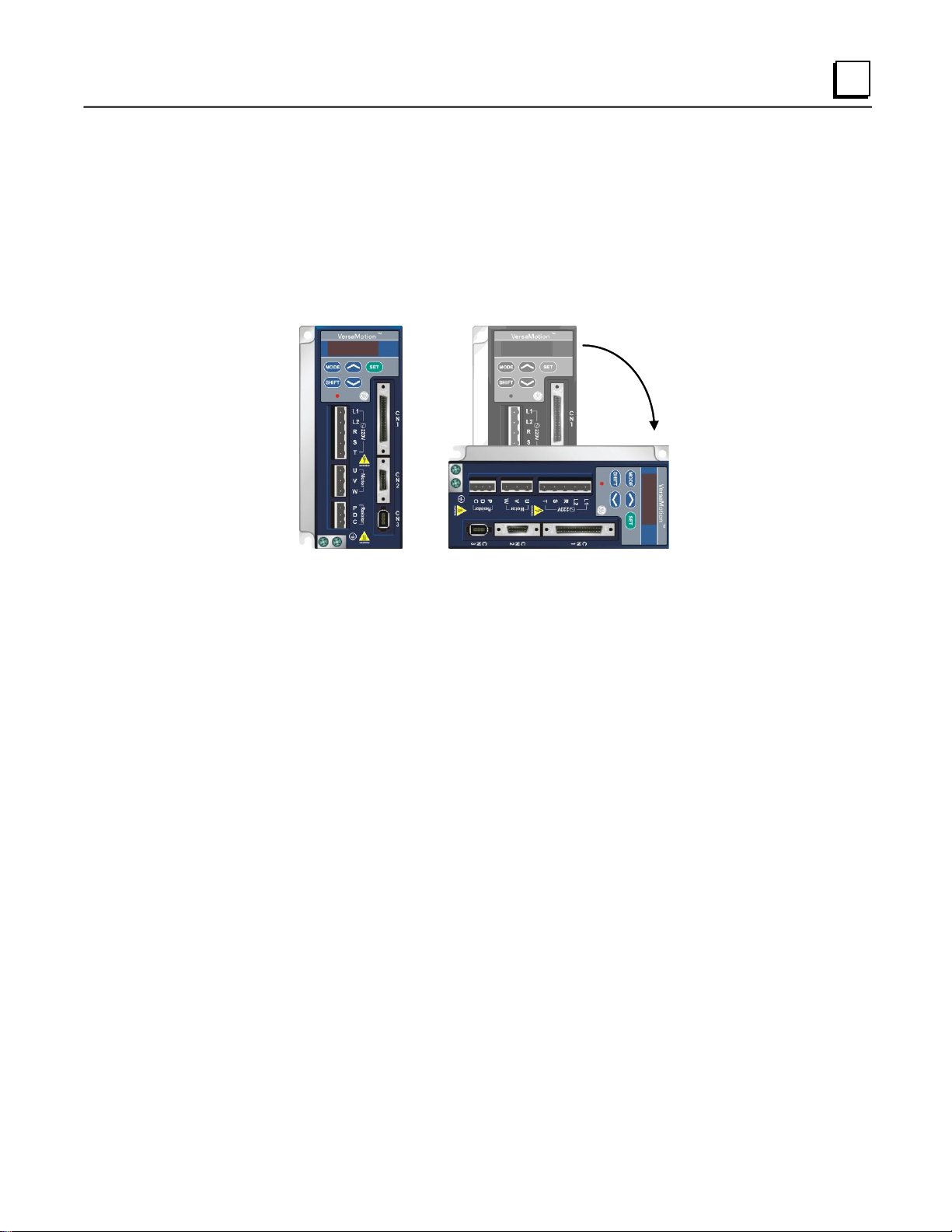
1
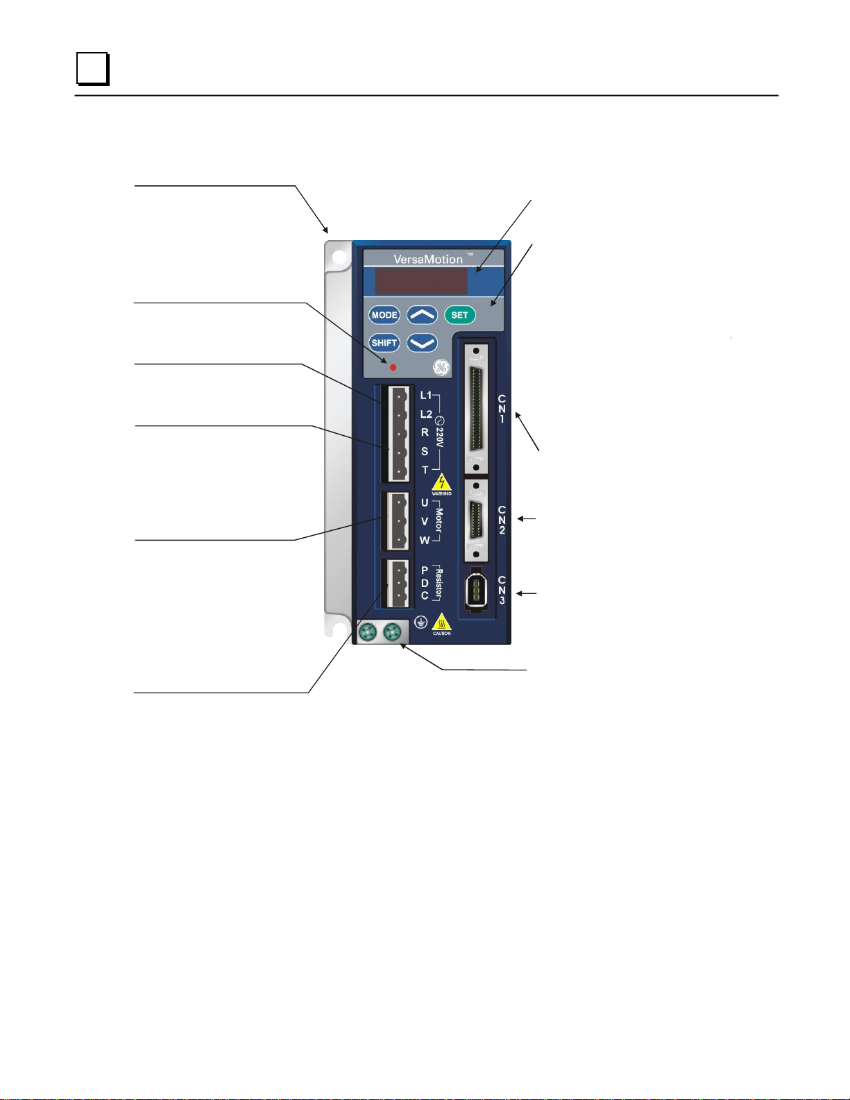
LED Display
The 5 digit, 7 segment LED displays
the servo status or
fault codes
Heatsink
Used to secure servo drive and for
heat dissipation
Charge LED
A lit LED indicates that either power is
connected to the servo drive OR a
residual charge is present in the drive's
internal power components.
DO NOT TOUCH ANY ELECTRICAL
CONNECTIONS WHILE THIS LED IS LIT.
(Please refer to the Safety Precautions on
page i).
Control Circuit Terminal (L1, L2)
Used to connect
single-phase VAC supply.
50/60Hz
200~230Vac,
Main Circuit Terminal (R, S, T)
Used to connect
commercial power supply
50/60Hz
200~230V,
Ground Terminal
Servo Motor Output (U, V, W)
Used to connect servo motor. Never
connect the output terminal to main
circuit power.
The AC servo drive
may be destroyed beyond repair if
incorrect cables are connected to
the output terminals.
Internal / External Regenerative
Resistor Terminal
1)
resistor, connect P and C to the
regenerative resistor and ensure that
the circuit between P and D
is open.
2) When using the internal regenerative
resistor, ensure that the circuit
between P and D is closed and the
circuit between P and C is open.
When using an external regenerative
Operation Panel
Used function keys to perform status
display, monitor and diagnostic, function
and parameter setting.
Function Keys:
MODE : Press this key to select/change
mode
SHIFT :
Press this key to shift
left
UP : Press this key to increase values
on the display
DOWN :
Press this key to decrease
values on the display
SET : Press this key to store data
Shift Key has several functions:
moving the cursor and indexing
through the parameter groups
cursor to
the
I/O Interface
Used to connect Host Controller (PLC)
or control I/O signal
Encoder Interface
Used to connect Encoder of
Servo Motor
Serial Communication Interface
For RS-485 / 232 / 422 serial
communication
Used to connect personal computer
or other controllers
1.1.1 Servo Drive Features
1-4 VersaMotion User’s Manual – October 2012 GFK-2480A
Page 13

1
1.1.2 VersaMotion System Architectures
The VersaMotion servos can be used in the following types of system architectures:
As a standalone simple position indexer using up to eight stored positions that are selected and
triggered using discrete inputs or the serial communication interface. Positions can be
configured or changed using a teach function or over the serial communication interface.
Simple electronic gearing (pulse follower) using a configurable fixed gear ratio is also
supported.
With the VersaMax Micro 20/40/64 built-in CPU motion functions.
With the VersaMax Micro two-axis motion expansion module using the 500 KHz pulse
command interface for application that require more complex motion sequences, such as basic
positioning with registration control.
With Quick Panel Control and the VersaMax Micro two-axis motion expansion module using
the 500 KHz pulse command interface to provide an integrated motion, logic and view solution.
With a DSM314 Motion Controller using either an analog velocity or analog torque command.
1.1.3 VersaMotion System Components
A complete and workable VersaMotion servo system includes the following parts:
1) Servo amplifier
2) Servo motor
3) One operating lever (for wire to terminal block insertion)
4) One power cable, which is used to connect the servo motor and the servo drive’s U, V,
and W terminals.
5) One encoder cable, which is used to connect the encoder of servo motor and CN2
terminal of servo drive.
6) CN1 I/O connector: 50 pin Connector (IC800VMACONCN1), Breakout Terminal Board
and Cable Kit (IC800VMTBC005), or Flying Lead I/O Cable (IC800VMCI010 — 1
meter) or IC800VMCI030 — 3meter)
7) CN3 serial communication cable (IC800VMCS030)
For 100W — 1KW models:
8) Five-pin Terminal Block for L1, L2, R, S, T (Included with amplifier.)
9) Three-pin Terminal Block for U, V, W (Included with amplifier.)
10) Three-pin Terminal Block for P, D, C (Included with amplifier.
Note: The 2kW and 3kW amplifiers have built-in terminal blocks.
GFK-2480A Chapter 1 Introduction 1-5
Page 14

1
IC800VMA 30 2
VersaMotion Amplifier
Power Rating
01 = 100 Watt 10 = 1000 Watt
02 = 200 Watt 20 = 2000 Watt
04 = 400 Watt 30 = 3000 Watt
07 = 750 Watt
Voltage
2 = 200–230 VAC, 1 or 3 phase (100-750W)
2 = 200–230 VAC, 3 phase (2kW & 3kW)
Part Number
Power Rating (Watts)
IC800VMA012
100
IC800VMA022
200
IC800VMA042
400
IC800VMA072
750
IC800VMA102
1000
IC800VMA202
2000
IC800VMA302
3000
IC800VMM 30 L N KS E25
VersaMotion Motor
Power Rating
01 = 100 Watt
02 = 200 Watt
04 = 400 Watt
07 = 750 Watt
10 = 1000 Watt
20 = 2000 Watt
30 = 3000 Watt
Feedback
E25 = 2500 PPR Encoder
Shaft Configuration
KS= Straight Shaft, Key & Oil Seal
Inertia Type
L = Low Inertia
Brake
N = No Brake
B = 24 VDC Holding Brake
Part Number
Power Rating (Watts)
IC800VMM01LNKSE25
100
IC800VMM02LNKSE25
200
IC800VMM04LNKSE25
400
IC800VMM07LNKSE25
700
IC800VMM10LNKSE25
1000
IC800VMM20LNKSE25
2000
IC800VMM30LNKSE25
3000
Amplifiers
Motors
Without brake
1-6 VersaMotion User’s Manual – October 2012 GFK-2480A
Page 15
1
Part Number
Power Rating (Watts)
IC800VMM01LBKSE25
100
IC800VMM02LBKSE25
200
IC800VMM04LBKSE25
400
IC800VMM07LBKSE25
700
IC800VMM10LBKSE25
1000
IC800VMM20LBKSE25
2000
IC800VMM30LBKSE25
3000
Part Number
Description
IC800VMCExxx
Encoder Cable (100W to 750W)
IC800VMCE1xxx
Encoder Cable (1000W & larger)
Part Number
Description
IC800VMCPxxx
Motor Power Cable (100W to 750W)
IC800VMCP1xxx
Motor Power Cable (1kW)
IC800VMCP2xxx
Motor Power Cable (2kW & 3kW)
Part Number
Description
IC800VMCBxxx
Motor Power & Brake Cable (200W to 750W)
IC800VMCB1xxx
Motor Power & Brake Cable (1kW)
IC800VMCB2xxx
Motor Power & Brake Cable (2kW & 3kW)
With Brake
Accessories
Cables
Note: xxx = length in 0.1 meter increments.
Standard lengths (other lengths available):
xxx=030 3 meters
xxx=050 5 meters
xxx=100 10 meters
xxx=200 20 meters
Encoder Cables
Motor Power Cables
Motor Power & Brake Cables
Note: The 100 Watt motor does not have a brake option.
GFK-2480A Chapter 1 Introduction 1-7
Page 16
1
Part Number
Description
IC800VMCS030
Serial Cable, 3 meter
Part Number
Description
IC800VMBR040
40 ohm 400 watt
IC800VMBR020
20 ohm 1000 watt
Part Number
Description
IC800VMACONCN1
Amplifier CN1 Serial Communication Connector
IC800VMACONCN2
Amplifier CN2 Encoder Connector
IC800VMACONCN3
Amplifier CN3 Serial Communications Connector
IC800VMTBC005
Breakout Terminal Board with 0.5 m Cable
IC800VMMCONE001
Motor Encoder Connector (100W-750W)
IC800VMMCONE002
Motor Encoder Connector (1000W & larger)
IC800VMMCONP002
Motor Power Connector (100-750W, With Brake)
IC800VMMCONP001
Motor Power Connector (100-750W, No Brake)
IC800VMMCONP003
Motor Power Connector (1kW-3kW)
Part Number
Description
IC800VMACONMTRP
Amplifier Motor Power Connector
IC800VMADBR001
Amplifier External Braking Resistor Connector
Serial Cable
Regeneration Resistors
Amplifier Connectors
Amplifier Terminal Blocks
1-8 VersaMotion User’s Manual – October 2012 GFK-2480A
Page 17
1
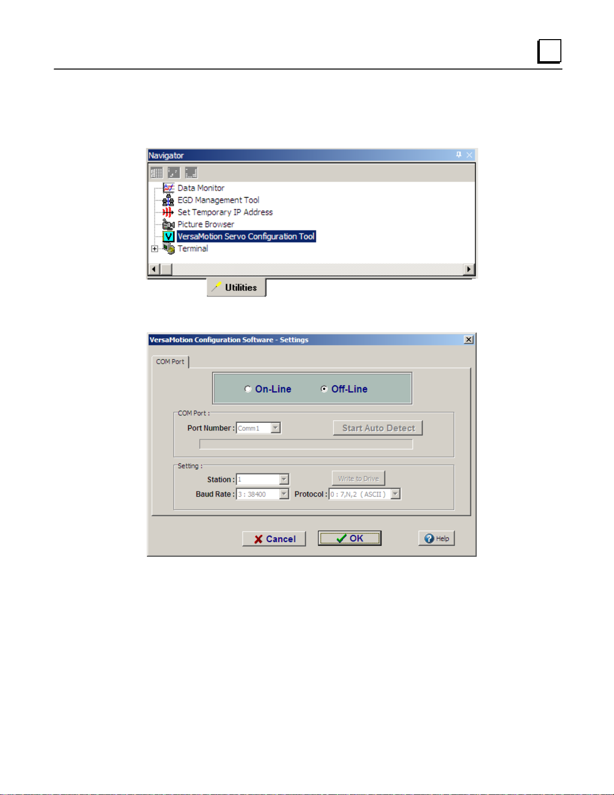
1.1.4 VersaMotion Configuration Software
The VersaMotion servo configuration tool is provided with Proficy Machine Edition version 5.70, SIM 1.
To access the configuration tool, select it on the Utilities tab in the Machine Edition Navigator window.
The VersaMotion Settings dialog box appears. To work in offline mode, click OK. To configure a
communications port for the software tool, select On-Line and click OK.
GFK-2480A Chapter 1 Introduction 1-9
Page 18

1
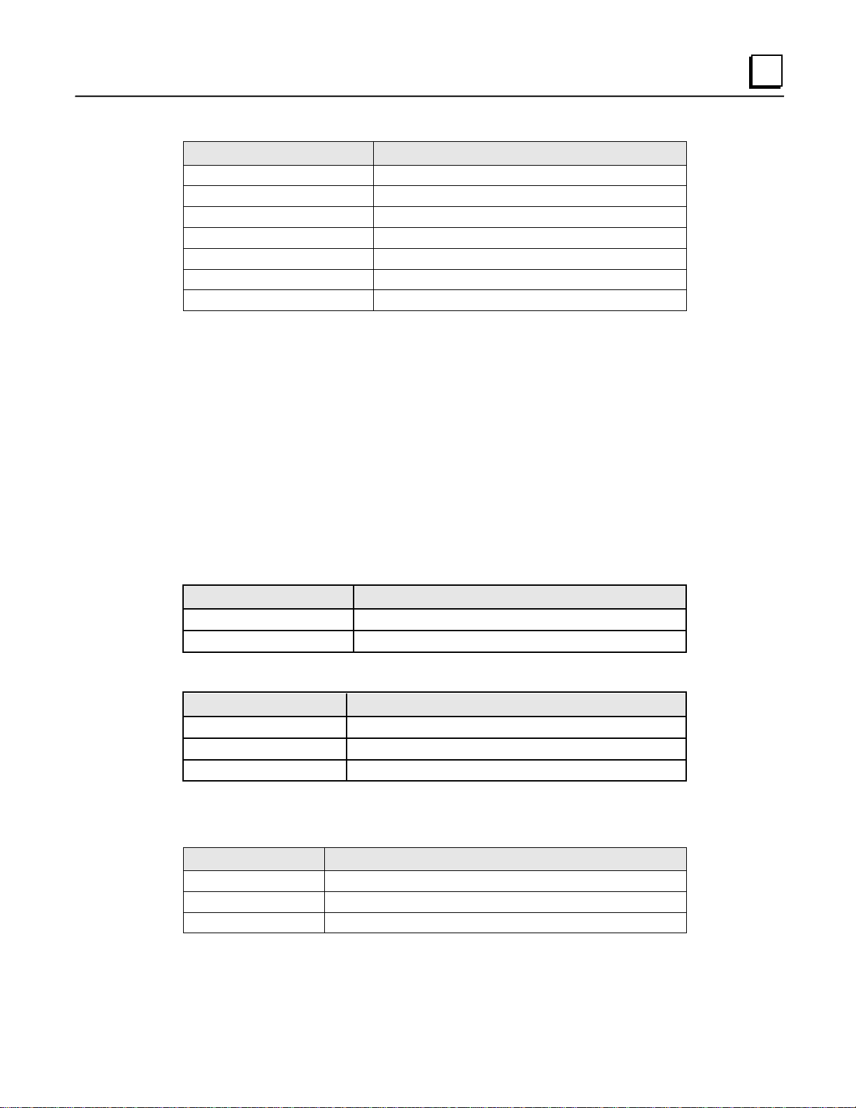
Settings
Allows you to go online with the VersaMotion drive
Scope
Opens the oscilloscope view
Auto Gain Tuning
Opens tool for calculating servo gain values
Digital IO/Jog Control
Allows you to view and change the digital IO functions in the
servo drive
Status Monitor
Allows you to monitor the servo motor status.
Model Information
Lists communications port information, drive model information,
and motor specifications.
Alarm Information
Displays information for current alarms and alarm history.
Parameter Editor
Allows you to view the values of all servo drive parameters.
Some parameters can be set while online with the servo drive.
Parameter Wizard
Allows you to read the current parameter settings, select the
control mode, edit selected parameter values, or save a set of
parameter values to a file.
User Manual
Online help for the VersaMotion software.
Parameter Manual
Provides a summary of servo drive parameters.
VersaMotion Information
Provides version information for the VersaMotion software.
VersaMotion Software provides the following tools:
1-10 VersaMotion User’s Manual – October 2012 GFK-2480A
Page 19
1
Power
Rating
Servo Drives
Servo Motors
Without Brake
With Brake
100W
IC800VMA012
IC800VMM01LNKSE25
IC800VMM01LBKSE25
200W
IC800VMA022
IC800VMM02LNKSE25
IC800VMM02LBKSE25
400W
IC800VMA042
IC800VMM04LNKSE25
IC800VMM04LBKSE25
750W
IC800VMA072
IC800VMM07LNKSE25
IC800VMM07LBKSE25
1000W
IC800VMA102
IC800VMM10LNKSE25
IC800VMM10LBKSE25
2000W
IC800VMA202
IC800VMM20LNKSE25
IC800VMM20LBKSE25
3000W
IC800VMA302
IC800VMM30LNKSE25
IC800VMM30LBKSE25
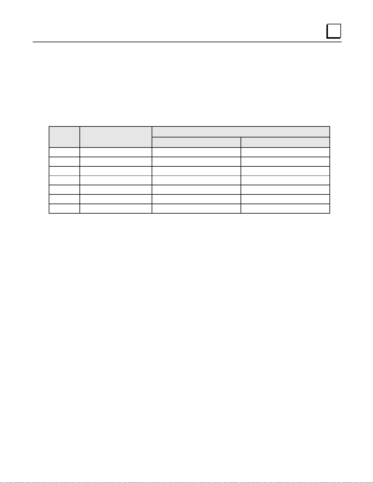
1.2 Servo Drive and Servo Motor Combinations
The servo drives are designed for use in combination with specific servo motors. The table below
shows the possible combinations of VersaMotion servo drives and motors.
The servo drive and motor must be correctly matched for size (power rating). If the power of motor and
drive is not within the specifications, the drive and motor may overheat and servo alarm would be
activated. For detailed specifications of servo drives and motors, please refer to Chapter 11
“Specifications”.
GFK-2480A Chapter 1 Introduction 1-11
Page 20

1
Single Modes
Code
Description
External Position Control
Pt
Position control for the servo motor is achieved via an external
pulse command.
Internal Position Control
Pr
Position control for the servo motor is achieved via by eight
commands stored in the servo controller. Digital Inputs (DI)
control execution of the position commands.
Speed Control
S
Speed control for the servo motor is provided by either Internal
Preset Speed Parameters or External analog -10 to +10VDC
command. If using the Internal Preset Speed Parameters, the
three individual speeds are selected via digital inputs.
Note: S mode is a dual mode. The Internal Preset Speeds have
priority over the analog input. At any point when an Internal
Preset Speed is selected via a digital input, it will take priority
over the incoming External analog command.
Internal Speed Control
Sz
Speed control for the servo motor is provided by Internal Preset
Speed Parameters only. The individual speed commands are
selected via digital inputs. (A maximum of three speeds can be
stored internally).
Torque Control
T
Torque control for the servo motor is provided by either Internal
Preset Torque Parameters or External analog -10 to +10VDC
command. If using the Internal Preset Torque Parameters, the
three individual torques are selected via digital inputs.
Note: T mode is a dual mode. The Internal Preset Torque has
priority over the analog input. At any point when an Internal
Preset Torque command is selected via a digital input, it will
take priority over the incoming External analog command.
Internal Torque Control
Tz
Torque control for the servo motor is provided by Internal Preset
Torque Parameters only. The individual torque commands are
selected via digital inputs. (A maximum of three torque levels
can be stored internally).
1.3 Servo Drive Control Modes
The VersaMotion servo can be programmed to provide six single and five dual modes of operation,
which are described in the following table. For information on operating in each control mode, refer to
chapter 6.
1-12 VersaMotion User’s Manual – October 2012 GFK-2480A
Page 21

1
Dual Modes
Code
Description
Position (pulse train) Speed
Pt-S
Either Pt or S control mode can be selected via the Digital Inputs
(DI)
When switched to Speed mode the user has the option to use
Internal Preset Speed commands or External analog -10 to
+10VDC command as described in the Speed Mode details.
Position (pulse train) Torque
Pt-T
Either Pt or T control mode can be selected via the Digital Inputs
(DI).
When switched to Torque mode the user than has the option to
use Internal Preset Torque commands or External analog -10 to
+10VDC command as described in the Torque Mode details.
Position (internal register) Speed
Pr-S
Either Pr or S control mode can be selected via the Digital
Inputs (DI)
When switched to Speed mode the user has the option to use
Internal Preset Speed commands or External analog -10 to
+10VDC command as described in the Speed Mode details.
Position (internal register) Torque
Pr-T
Either Pr or T control mode can be selected via the Digital Inputs
(DI).
When switched to Torque mode the user than has the option to
use Internal Preset Torque commands or External analog -10 to
+10VDC command as described in the Torque Mode details.
Speed - Torque
S-T
Either S or T control mode can be selected via the Digital Inputs
(DI).
When switched to Speed mode the user than has the option to
use Internal Preset Speed commands or External analog -10 to
+10VDC command as described in the Speed Mode details.
When switched to Torque mode the user than has the option to
use Internal Preset Torque commands or External analog -10 to
+10VDC command as described in the Torque Mode details.
GFK-2480A Chapter 1 Introduction 1-13
Page 22

Page 23

Chapter
2
Unpacking and Installation
This chapter provides the following information:
Page
2.1 Unpacking and Inspection 2-2
2.2 Storage Conditions 2-2
2.3 Installation 2-3
2.4 Molded-Case Circuit Breaker, Fuse and Leakage Current 2-8
Note: In this manual, actual measured values are in metric units. Dimensions in SI units are for
reference only. Please use metric units for precise measurements.
GFK-2480A 2-1
Page 24

2
2.1 Unpacking and Inspection
Warning
Ensure that both the servo drive and motor are correctly matched for size (power
rating). Failure to observe this precaution may cause fire, seriously damage the
drive or motor, or cause personal injury.
After receiving the AC servo drive, please check for the following:
Ensure that the product is what you have ordered.
Verify the part number indicated on the nameplate corresponds with the part number of your order.
Ensure that the servo motor shaft rotates freely.
Rotate the motor shaft by hand; a smooth rotation will indicate a good motor. However, a servo
motor with an electromagnetic brake cannot be rotated manually.
Check for damage.
Inspect the unit to insure it was not damaged during shipment.
Check for loose screws.
Ensure that all necessary screws are tight and secure.
If any items are damaged or incorrect, contact the distributor from whom you purchased the product.
2.2 Storage Conditions
The product should be kept in the shipping carton before installation. In order to retain the warranty
coverage, the servo drive should be stored properly when it is not to be used for an extended period of
time. Some storage suggestions are:
Store in a clean and dry location free from direct sunlight.
Store within an ambient temperature range of -20°C to +65°C (-4°F to 149°F).
Store within a non-condensing relative humidity range of 0% to 90%.
Do not store in a place subjected to corrosive gases and liquids.
The product should be correctly packaged and placed on a solid surface.
2-2 VersaMotionServo Motors and Amplifiers User’s Manual – October 2012 GFK-2480A
Page 25

2
2.3 Installation
2.3.1 Installation Notes
Do not bend or strain the cables between the servo drive and the motor.
When mounting the servo drive, tighten screws to secure the drive in place.
If the servo motor shaft is coupled directly to a rotating device, ensure that the alignment
specifications of the servo motor, coupling, and device are followed. Failure to do so may
cause unexpected loads or premature failure of the servo motor.
If the length of cable connected between servo drive and motor is more than 20m, the wire
gauge of the encoder and motor connection cables (connected to U, V, W terminals) should be
increased. For wire gauge recommendations, refer to chapter 3.
Make sure to properly tighten the motor mounting bolts.
2.3.2 Installation Conditions
Warning
Do not install the product in a location that is outside the stated specification for
the drive and motor. Failure to observe this caution may result in electric shock,
fire, or personal injury.
VersaMotion drives are open type servo drives and must be installed in a NEMA enclosure, such as a
protected control panel, during operation to comply with the requirements of international safety
standards. They provide precise feedback control and high-speed calculation functions incorporating
DSP (Digital Signal Processor) technology, and are intended to drive three-phase permanent magnet
synchronous motors (PMSM) to achieve precise positioning by means of accurate current output
generated by IGBT (Insulated Gate Bipolar Transistor).
VersaMotion drives can be used in industrial applications and for installation in an end-use enclosure
that conforms to the specifications provided in this manual (Drives, cables and motors are for use in a
suitable enclosure with a minimum of a UL Type 1 rating).
GFK-2480A Chapter 2 Unpacking and Installation 2-3
Page 26

2
Operating Temperature
VersaMotion Servo Drives: 0°C to 55°C (32°F to 131°F)
VersaMotion Servo Motors: 0°C to 40°C (32°F to 104°F)
For long-term reliability, the ambient temperature of the servo drive should be less than 45°C (113°F).
If the ambient temperature of servo drive is greater than 45°C (113°F), install the drive in a well-
ventilated location and do not obstruct the airflow of the cooling fan.
Caution
The servo drive and motor will generate heat. If they are installed in a control
panel, allow sufficient space around the units for heat dissipation.
Observe the following precautions when selecting a mounting location.
Do not mount the servo drive or motor adjacent to heat-radiating elements or in direct sunlight.
Do not mount the servo drive or motor in a location subjected to corrosive gases, liquids, or
airborne dust or metallic particles.
Do not mount the servo drive or motor in a location where temperature and humidity will
exceed the specifications.
Do not mount the servo drive or motor in a location where vibration and shock will exceed the
specifications.
Do not mount the servo drive or motor in a location where it will be subjected to high levels of
electromagnetic radiation.
2-4 VersaMotionServo Motors and Amplifiers User’s Manual – October 2012 GFK-2480A
Page 27
2
Correct
Incorrect
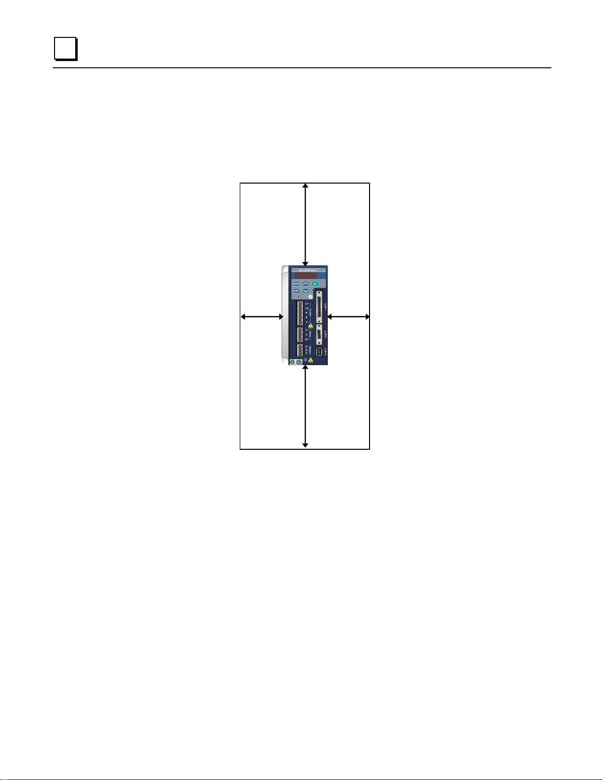
2.3.4 Installation Procedure and Minimum Clearances
Incorrect installation may result in a drive malfunction or premature failure of the drive and or motor.
Please follow the guidelines in this manual when installing the servo drive and motor.
The VersaMotion servo drive should be mounted perpendicular to the wall or in the control panel. In
order to ensure the drive is well ventilated, allow sufficient free space surrounding the servo drive and
do not obstruct the ventilation holes. Do not install the drive in a horizontal position or malfunction and
damage will occur.
Drive Mounting
The servo drives must be back-mounted vertically on a dry and solid surface such as a NEMA
enclosure. A minimum spacing of two inches must be maintained above and below the drive for
ventilation and heat dissipation. Additional space may be necessary for wiring and cable connections.
Also, the mounting surface should be able to conduct heat away from the mounting plate and not
conduct into the drive from external sources.
Motor Mounting
The servo motors should be mounted firmly to a dry and solid mounting surface to ensure maximum
heat transfer for maximum power output and to provide a good ground.
For dimensions and weight specifications of the servo drives and motors, refer to Chapter 11,
“Specifications".
GFK-2480A Chapter 2 Unpacking and Installation 2-5
Page 28
2
20mm
(0.8in)
min.
20mm
(0.8in)
min.
50mm
(2.0in)
min.
50mm
(2.0in)
min.
Minimum Clearances
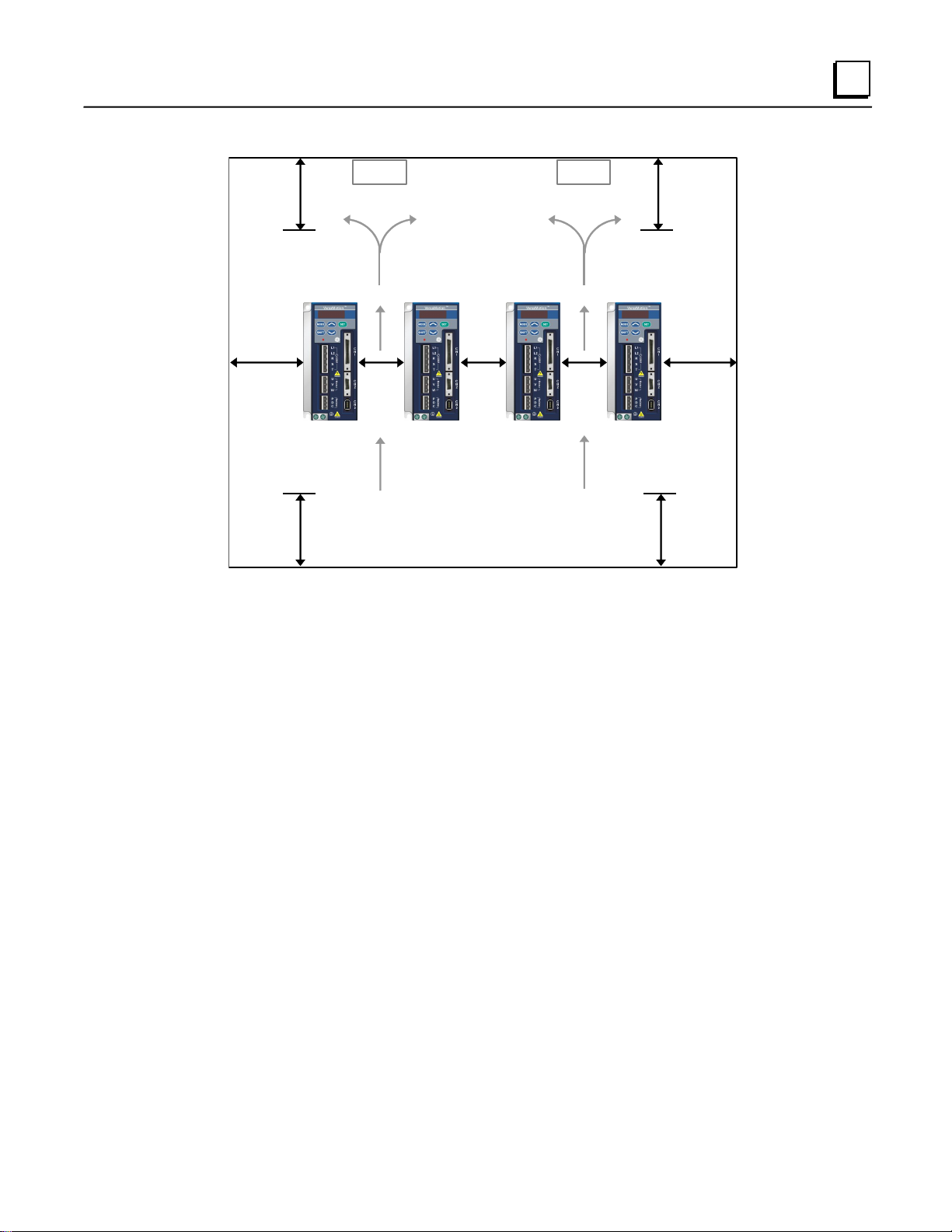
Install a fan to increase ventilation to avoid ambient temperatures that exceed the specification. When
installing two or more drives adjacent to each other, allow clearances as shown in the following
diagram.
Minimum Clearances
2-6 VersaMotionServo Motors and Amplifiers User’s Manual – October 2012 GFK-2480A
Page 29
2
40mm
(1.16 in)
min.
40mm
(1.16 in)
min.
10mm
(0.4 in)
min.
10mm
(0.4 in)
min.
10mm
(0.4 in)
min.
100mm
(4.0 in)
min.
100mm
(4.0 in)
min.
100mm
(4.0 in)
min.
100mm
(4.0 in)
min.
Air flow
Air flow
Fan
Fan
Side by Side Installation
GFK-2480A Chapter 2 Unpacking and Installation 2-7
Page 30
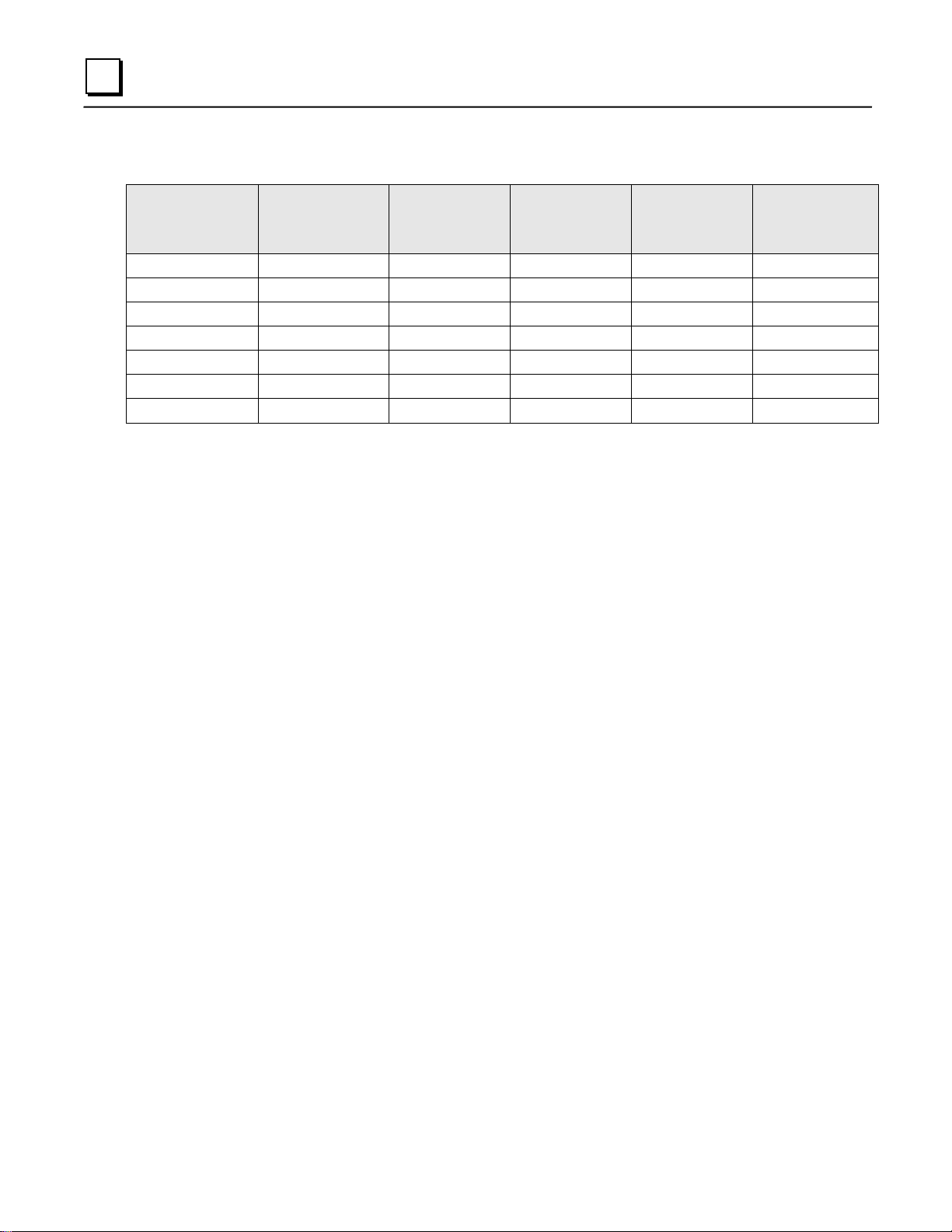
2
Drive Part No.
Output Short
Circuit
Breaker
Fuse
3-Phase
Operation
Leakage Current
1-Phase
Operation
Leakage Current
IC800VMA012
8.4A (peak)
5A
5A
0.06mA
0.16mA
IC800VMA022
8.4A (peak)
5A
5A
0.06mA
0.16mA
IC800VMA042
25A (peak)
10A
20A
0.08mA
0.2mA
IC800VMA072
42A (peak)
10A
20A
0.08mA
0.2mA
IC800VMA102
60A (peak)
15A
25A
0.08mA
0.2mA
IC800VMA202
73A (peak)
30A
60A
0.12mA
-
IC800VMA302
107A (peak)
30A
80A
0.13mA
-
2.4 Molded-Case Circuit Breaker, Fuse and Leakage Current
2-8 VersaMotionServo Motors and Amplifiers User’s Manual – October 2012 GFK-2480A
Page 31

Chapter
3
Equipment Connections and Wiring
This chapter provides information on wiring VersaMotion products, descriptions of I/O signals, and
sample wiring diagrams.
Page
3.1 Equipment Connections 3-2
3.2 Basic Wiring 3-9
3.3 Input / Output Interface Connector CN1 3-11
3.4 Encoder Connector CN2 3-33
3.5 Serial Communication Connector CN3 3-34
3.6 Standard Connection Example 3-36
Warning
Install the encoder cables in a separate conduit or wire tray from the motor
power cables to avoid signal noise. Separate the conduits or trays by 30cm
(11.8inches).
Use multi-stranded twisted-pair wires or multi-core shielded-pair wires for
encoder feedback cables. The maximum length of command input cable is 3m
(9.84ft). The maximum length of encoder feedback cables is20m (66ft).
A charge with hazardous voltages may still remain in the drive after power has
been removed. Wait at least 10 minutes after power has been removed before
performing any wiring and/or inspection.
Caution
Connect wiring after the terminal blocks are all removed from the drive.
Insert only one wire into a terminal on the terminal block.
When inserting wires, ensure that the conductors are not shorted to adjacent
terminals or wires.
Double check the wiring before applying power to the drive. If the wiring is in
error, perform the wiring again with proper tools.
Never use force to remove the terminals or wires. Otherwise, , as it may result in
malfunction or damage.
GFK-2480A 3-1
Page 32

3
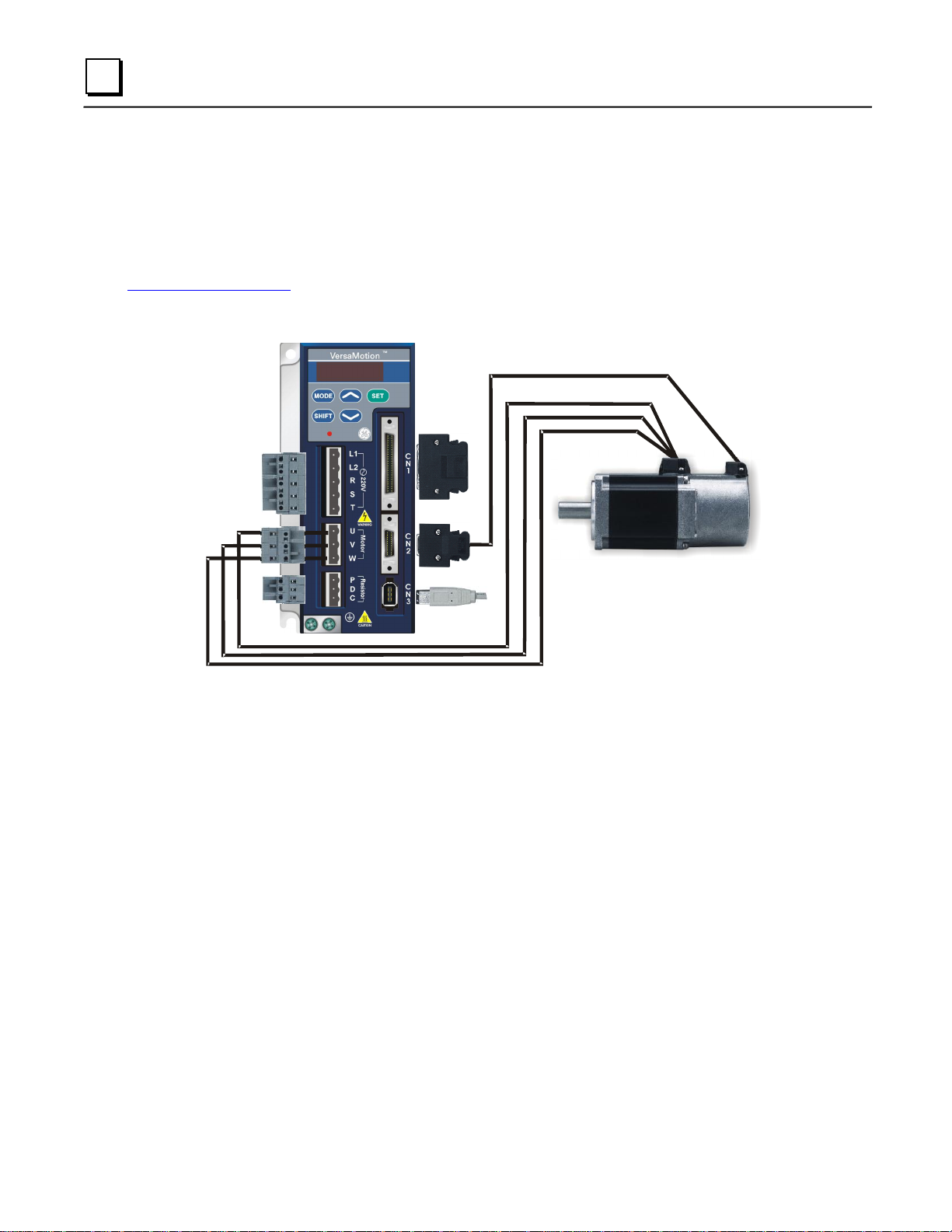
3.1 Equipment Connections
3.1.1 Connecting to Peripheral Devices
The following figure illustrates how to connect the peripheral devices.
When using an external regenerative resistor, connect the resistor to terminals P and C on the Servo
Drive, and ensure an open circuit between P and D. When using an internal regenerative resistor,
ensure the connection between P and D is closed, and P and C is open.
3-2 VersaMotionServo Motors and Amplifiers User’s Manual – October 2012 GFK-2480A
Page 33

3
Identification
Terminal
Description
Notes
L1, L2
Control circuit
terminal
The servo Control Circuit requires an independent 220V
single-phase VAC supply.
R, S, T
Main circuit
terminal
The Main Circuit Terminal is used to supply the servo with line
power. If a single-phase supply is used, connect the R and S
terminals to power. If three-phase power is used, connect all three
terminals, R, S, and T. To provide Control Circuit power, add two
jumpers: from R to L1 and S and L2.
U, V, W, FG
Servo motor
output
Used to connect servo motor.
Terminal Symbols:
U
V
W
FG
P, D, C
Regenerative
resistor terminal
Internal
resistor
Ensure the circuit is closed between P and D,
and the circuit is open between P and C.
External
resistor
Connect the regenerative resistor to P and C,
and ensure an open circuit between P and D.
two places
Ground terminal
Used to connect grounding wire of power supply and servo motor.
CN1
I/O connector
Used to connect external controllers. For details, refer to “3.3
Input/Output Interface Connector CN1” on page 3-11.
CN2
Encoder
connector
Used to connect encoder to servo motor and drive I/O. For details,
refer to “3.4 Encoder Connector CN2” on page 3-33.
Terminal Symbols:
A
/A
B
/B
Z
/Z
+5V
GND
CN3
Communication
connector
Used to connect PC. For details, refer to “Serial Communication
Connector CN3” on page 3-34
3.1.2 Servo Drive Connectors and Terminals
Note: U, V, W, CN1, CN2, CN3 terminals provide short circuit protection.
GFK-2480A Chapter 3 Equipment Connections and Wiring 3-3
Page 34

3
3.1.3 Wiring Notes
Warning
Connect the ground terminals to a class-3 ground (Ground resistance should not
exceed 100 Ω). Improper grounding may result in electric shock or fire.
Do not connect a power supply to the U, V and W terminals. Failure to observe
this precaution may result in serious injury, damage to the drive or fire.
Ensure that all screws, connectors and wire terminations are secure on the
power supply, servo drive and motor. Failure to observe this caution may result
in damage, fire or personal injury.
Please observe the following wiring notes while performing wiring and touching any electrical
connections on the servo drive or servo motor.
1. Verify the power supply and wiring of the power terminals (R, S, T, U, V, & W) is correct.
2. Use shielded twisted-pair cables for wiring to prevent voltage coupling and eliminate electrical
noise and interference.
3. Because a residual hazardous voltage may remain inside the drive, do not immediately touch any
of the power terminals (R, S, T, U, V, & W) and/or the cables connected to them after the power
has been turned off and the Charge LED is lit. (Refer to the safety precautions on page 3-1.)
4. The cables connected to R, S, T and U, V, W terminals should be placed in separate conduits from
the encoder or other signal cables. Separate them by at least 12 inches (30cm).
5. The encoder cable should use a twisted-shield signal wire with grounding conductor. The wire
length should be 65.62ft. (20m) or less. For lengths greater than 65.62ft. (20m), the wire gauge
should be doubled in order to lessen any signal attenuation.
6. The motor power cable should use 600V PTFE wire and the wire length should be less than 98.4ft.
(30m). If the wiring distance is longer than 98.4ft. (30m), choose adequate wire size according to
the voltage.
7. The shield of shielded twisted-pair cables should be connected to the ground (terminal marked )
of the servo drive.
8. For connector and cable specifications, refer to “3.1.6 Encoder Connector Specifications” on page
3-7.
3-4 VersaMotionServo Motors and Amplifiers User’s Manual – October 2012 GFK-2480A
Page 35

3
3.1.4 Wiring Methods
For servo drives from 100W to 1.0KW the input power can be either single or three-phase. For servo
drives 2kW and above only three-phase connections are available.
In the following wiring diagram figures:
Power ON: contact “a” (normally open)
Power OFF or Alarm Processing: contact “b” (normally closed)
1MC/x: coil of electromagnetic contactor
1MC/a: self-holding power
1MC: contact of main circuit power
Single-Phase Power Supply Connection
Three-Phase Power Supply Connection
GFK-2480A Chapter 3 Equipment Connections and Wiring 3-5
Page 36

3
Servo Drive
Power Rating
Motor Part Number
Description
U, V, W / Electromagnetic Brake Connector
Terminal
Id.
No Brake
100W
IC800VMM01LNKSE25
A
200W
IC800VMM02LNKSE25
400W
IC800VMM04LNKSE25
750W
IC800VMM07LNKSE25
Brake
200W
IC800VMM02LBKSE25
B
400W
IC800VMM04LBKSE25
750W
IC800VMM07LBKSE25
With or Without Brake
1kW
IC800VMM10LNKSE25
IC800VMM10LBKSE25
3106A-20-18S
C
2kW
IC800VMM20LNKSE25
IC800VMM20LBKSE25
3kW
IC800VMM30LNKSE25
IC800VMM30LBKSE25
3106A-24-11S
D
Terminal
Identification
U
V
W
CASE GROUND
BRAKE1
BRAKE2
A
1 2 3 4 -
-
B
1 2 4 5 3
6
C F I B E
G H D
D E F G A
B
3.1.5 Motor Power Cable Connector Specifications
Note: The brake coil has no polarity. The terminal identification names are BRAKE1 and BRAKE2.
The power supply for the brake is 24 VDC. Never use it for VDD, the +24V source voltage.
3-6 VersaMotionServo Motors and Amplifiers User’s Manual – October 2012 GFK-2480A
Page 37

3
Servo Drive Capacity
Motor Model Name
Encoder Connector
Terminal
Identific
ation
100W
IC800VMM01LNKSE25
HOUSING: AMP (1-172161-9)
A
200W
200WIC800VMM02LNKSE
25 IC800VMM02LBKSE25
200W
IC800VMM02LNKSE25
IC800VMM02LBKSE25
400W
400WIC800VMM04LNKSE
25 IC800VMM04LBKSE25
400W
IC800VMM04LNKSE25
IC800VMM04LBKSE25
750W
750WIC800VMM07LNKSE
25 IC800VMM07LBKSE25
750W
IC800VMM07LNKSE25
IC800VMM07LBKSE25
1kW
IC800VMM10LNKSE25
IC800VMM10LBKSE25
20-29 17-#16
B
2kW
2kWIC800VMM20LNKSE2
5 IC800VMM20LBKSE25
2kW
IC800VMM20LNKSE25
IC800VMM20LBKSE25
3kW
3kWIC800VMM30LNKSE2
5 IC800VMM30LBKSE25
3kW
IC800VMM30LNKSE25
IC800VMM30LBKSE25
Terminal
Identification
AMP (1-
172161-9)
A
/A
B
/B
Z
/Z
+5V
GND
BRAID
SHELD
A
1 4 2 5 3 6 7 8 9
Terminal
Identification
3106A-20-
29S
A
/A
B
/B
Z
/Z
+5V
GND
BRAID
SHELD
B
A B C D F G S R L
3.1.6 Encoder Connector Specifications
GFK-2480A Chapter 3 Equipment Connections and Wiring 3-7
Page 38

3
Servo Drive
Power Cable - Wire Gauge AWG (mm2)
L1, L2
R, S, T
U, V, W
P, C
IC800VMA012
AWG16 (1.31)
AWG14 (2)
AWG14 (2)
AWG14 (2)
IC800VMA022
AWG16 (1.31)
AWG14 (2)
AWG14 (2)
AWG14 (2)
IC800VMA042
AWG16 (1.31)
AWG14 (2)
AWG14 (2)
AWG14 (2)
IC800VMA072
AWG16 (1.31)
AWG14 (2)
AWG14 (2)
AWG14 (2)
IC800VMA102
AWG16 (1.31)
AWG14 (2)
AWG14 (2)
AWG14 (2)
IC800VMA202
AWG16 (1.31)
AWG14 (2)
AWG14 (2)
AWG14 (2)
IC800VMA302
AWG16 (1.31)
AWG12 (3.31)
AWG12 (3.31)
AWG14 (2)
Servo Drive
Encoder Cable - Wire Gauge AWG (mm2)
Wire Size
Core Number
UL Rating
IC800VMA012
AWG26 (0.13)
10 core (4 pair)
UL2464
IC800VMA022
AWG26 (0.13)
10 core (4 pair)
UL2464
IC800VMA042
AWG26 (0.13)
10 core (4 pair)
UL2464
IC800VMA072
AWG26 (0.13)
10 core (4 pair)
UL2464
IC800VMA102
AWG26 (0.13)
10 core (4 pair)
UL2464
IC800VMA202
AWG26 (0.13)
10 core (4 pair)
UL2464
IC800VMA302
AWG26 (0.13)
10 core (4 pair)
UL2464
3.1.7 Cable Specifications Power Cable
Power Cable
The following table lists recommended wire gauges for power cables of 30m (98.4ft.) or less.
Encoder Cable
The following table lists recommended wire gauges for encoder cables of 20m (65.62ft) or less. For
lengths greater than 20m (65.62ft.), the wire gauge should be doubled to avoid signal attenuation.
Notes:
1) Please use shielded twisted-pair cables for wiring to prevent voltage coupling and eliminate
electrical noise and interference.
2) The shield of shielded twisted-pair cables should be connected to the ground terminal (marked
) of the servo drive.
3-8 VersaMotionServo Motors and Amplifiers User’s Manual – October 2012 GFK-2480A
Page 39

3
3.2 Basic Wiring
3.2.1 Basic Wiring Schematic of 100W — 1.0kW Models
GFK-2480A Chapter 3 Equipment Connections and Wiring 3-9
Page 40

3
3.2.2 Basic Wiring Schematic of 2kW — 3kW Models
3-10 VersaMotionServo Motors and Amplifiers User’s Manual – October 2012 GFK-2480A
Page 41

3
3.3 Input/Output Interface Connector CN1
The CN1 Interface Connector provides access to three signal groups:
General interface for the analog speed and torque command, encoder reference signal
from the motor, pulse / direction inputs, and reference voltages.
Eight programmable Digital Inputs (DI), can be set using parameters P2-10 — P2-17
Five programmable Digital Outputs (DO), can be set using parameters P2-18 — P2-22
A detailed explanation of each group is provided in “3.3.3 CN1 Signal Description” on page 3-13
3.3.1 CN1 Terminal Identification
GFK-2480A Chapter 3 Equipment Connections and Wiring 3-11
Page 42

3
2
DO3-
Digital
output
4
DO2-
Digital
output
6
DO1-
Digital
output
8
DI4-
Digital
input
10
DI2-
Digital
input
12
GND
Analog
input
signal
ground
14
NC
NC
16
MON1
Analog
monitor
output 1
18
T_REF
Analog
torque
Input
20
VCC
+12V
power
output (for
analog
command)
22
/OA
Encoder
/A pulse
output
24
/OZ
Encoder
/Z pulse
output
1
DO4+
Digital
output
3
DO3+
Digital
output
5
DO2+
Digital
output
7
DO1+
Digital
output
9
DI1-
Digital
input
11
COM+
Power
input
(12 —
24V)
13
GND
Analog
input
signal
ground
15
MON2
Analog
monitor
output 2
17
VDD
+24V
power
output (for
external
I/O)
19
GND
Analog
input
signal
ground
21
OA
Encoder
A pulse
output
23
/OB
Encoder
/B pulse
output
25
OB
Encoder
B pulse
output
27
DO5-
Digital
output
29
NC
NC
31
DI7-
Digital
input
33
DI5-
Digital
input
35
PULL
HI
Pulse
applied
power
37
SIGN
Position
sign (-)
39
NC
NC
41
PULSE
Pulse
input (-)
43
/PULSE
Pulse
input (+)
45
COM-
VDD(24V)
power
ground
47
COM-
VDD(24V)
power
ground
49
COM-
VDD(24V)
power
ground
26
DO4-
Digital
output
28
DO5+
Digital
output
30
DI8-
Digital
input
32
DI6-
Digital
input
34
DI3-
Digital
input
36
/SIGN
Position
sign (+)
38
NC
NC
40
NC
NC
42
V_REF
Analog
speed
input (+)
44
GND
Analog
input
signal
ground
46
NC
NC
48
OCZ
Encoder
Z pulse
Open-coll
ector
output
50
OZ
Encoder
Z pulse
Line-drive
r output
3.3.2 CN1 Terminal Signal Identification
CAUTION
The terminals marked NC (No Connection) must be left unconnected. The NC
terminals are used within the servo drive. Any outside connection to the NC
terminals will result in damage to the drive.
3-12 VersaMotionServo Motors and Amplifiers User’s Manual – October 2012 GFK-2480A
Page 43

3
Signal
Pin
No.
Details
Wiring
Diagram
Analog
Signal
INPUT
V_REF
42
Motor speed command: -10V to +10V. Corresponds to
the maximum speed programmed. P1-55 Maximum
Speed Limit (Factory default 3000 RPM).
C1
T_REF
18
Motor torque command: -10V to +10V. Corresponds to 100% to +100% rated torque command.
C1
Analog
Monitor
OUTPUT
MON1
16
The MON1 and MON2 can be assigned drive and motor
parameters that can be monitored via an analogue
voltage.
C2
MON2
15
Please refer to parameter P0-03 for monitoring
commands and P1-04 / P1-05 for scaling factors.
Output voltage is reference to the power ground.
Position
Pulse
INPUT
PULSE (A)
41
The drive can accept two types of pulse inputs: Open
Collector and Line Driver.
Three different pulse commands can be selected via
parameter P1-00: Quadrature, CW + CCW pulse, and
Pulse/Direction.
C3/C4
/PULSE (/A)
43
SIGN (B)
37
/SIGN (/B)
36
PULL HI
35
If an Open Collector type of pulse is used, this terminal
must be pulled high to pin 17.
C3
Position
Pulse
OUTPUT
OA
21
The motor encoder signals are available through these
terminals. The encoder output pulse count can be set
using parameter P1-46.
C11/C12
/OA
22
OB
25
/OB
23
OZ
50
/OZ
24
Power
VDD
17
VDD is the +24V source voltage provided by the drive.
Maximum permissible current 500mA.
-
COM+
11
COM+ is the common voltage rail of the Digital Input and
Digital Output signals. Connect VDD to COM+ for source
mode. For external applied power sink mode (+12V to
+24V), the positive terminal should be connected to
COM+ and the negative to COM-.
COM-
45
47
49
3.3.3 CN1 Signal Description
The tables in this section detail the three groups of signals on the CN1 connector: General Signals,
Digital Output (DO) signals and Digital Input (DI) signals. The General Signals are set by the factory
and cannot be changed, reprogrammed or adjusted. The Digital Input and Digital Output signals can be
programmed by the users.
General Signals (non-configurable)
For wiring diagrams, see “3.3.5 Wiring Diagrams of I/O Signals (CN1)” on page 3-29.
GFK-2480A Chapter 3 Equipment Connections and Wiring 3-13
Page 44

3
Signal
Pin
No.
Details
Wiring
Diagram
Power
VCC
20
VCC is a +12V power rail provided by the drive. It can be
used for the input on an analog speed or torque
command. Maximum permissible current 100mA.
-
GND
12,13,
The polarity of VCC is with respect to Ground (GND).
19,44
Other
NC
14,29,
38,39,
40,46,
See previous note for NC terminals CN1 connector on
page 3-12.
-
48
DO
Signal
Name
DO
Parameter
Value
Assigned
Control
Mode
CN1 Pin
No.
(Default)
Details
Associated
Parameters
Wiring
Diagram
+
-
SRDY
01
ALL 7 6
Servo Ready (SRDY) is
activated when the servo
drive is ready to run. All
fault and alarm
conditions, if present,
have been cleared.
P2-51
C5/C6/C7/C8
SON
02
Not
assigned
- - Servo On (SON) is
activated when control
power is applied to the
servo drive.
C5/C6/C7/C8
Caution
Any outside connection to the NC terminals will result in damage to the drive.
Configurable Signals
The Digital Inputs (DI) and Digital Outputs (DO) have factory default settings that correspond to the
servo drive control modes, which are listed in chapter 1. However, both the DI and DO signals can be
configured independently to meet the requirements of the application.
The factory default settings of the DI and DO signals are listed in on pages 3-22 and 3-25.
The DI and DO signals and their corresponding pin numbers are factory set and cannot be changed.
However, the assigned signals and control modes are user configurable. For example, the factory
default function of DO5 (pins 28/27) can be assigned to DO1 (pins 7/6) and vice versa.
Digital Output (DO) Signals
For wiring diagrams, see “3.3.5 Wiring Diagrams of I/O Signals (CN1)” on page 3-29.
Functions of the digital outputs DO1 through DO5 can be selected using parameters P2-18 through
P2-22. For information on setting these parameters, refer to “Output Function Definitions” in chapter 7.
3-14 VersaMotionServo Motors and Amplifiers User’s Manual – October 2012 GFK-2480A
Page 45

3
DO
Signal
Name
DO
Parameter
Value
Assigned
Control
Mode
CN1 Pin
No.
(Default)
Details
Associated
Parameters
Wiring
Diagram
+
-
ZSPD
03
ALL 5 4
Zero Speed (ZSPD) is
activated when the drive
senses the motor speed
is equal to or below the
Zero Speed Range as
defined in parameter P1-
38. For example, at the
factory default setting,
ZSPD will be activated
when the drive detects
the motor rotating at or
below 10 rpm. ZSPD will
remain active until the
motor speed increases
above 10 RPM.
P1-38
C5/C6/C7/C8
TSPD
04
ALL 3 2
Target Speed (TSPD) is
activated once the drive
has detected the motor
has reached the Target
Speed setting as defined
in parameter P1-39.
TSPD will remain active
until the motor speed
drops below the Target
Speed.
P1-39.
C5/C6/C7/C8
TPOS
05
Pt, Pr, PtS, Pt-T,
Pr-S, Pr-T
1
26
When the drive is in Pt
mode, Target Position
(TPOS) will be activated
when the position error is
equal to or less than the
value of parameter P1-
54. When the drive is in
Pr mode, TPOS will be
activated when the drive
detects that the position
of the motor is in the
range between -P1-54
and +P1-54 of the target
position. For example, at
the factory default
setting, TPOS will
activate when the motor
is within -99 pulses of the
target position, then
deactivate after it
reaches +99 pulses of
the desired position.
P1-54
C5/C6/C7/C8
GFK-2480A Chapter 3 Equipment Connections and Wiring 3-15
Page 46

3
DO
Signal
Name
DO
Parameter
Value
Assigned
Control
Mode
CN1 Pin
No.
(Default)
Details
Associated
Parameters
Wiring
Diagram
+
-
TQL
06
Not
assigned
- - Torque Limit (TQL) is
activated when the drive
has detected that the
motor has reached the
torque limits set by either
the parameters P1-12 to
P1-14 or by an external
analog voltage.
P1-12 P1-
13 P1-14
C5/C6/C7/C8
ALRM
07
ALL
28
27
Alarm (ALRM) is
activated when the drive
has detected a fault
condition. However,
when a Reverse limit
error, Forward limit error,
Emergency stop, Serial
communication error, or
Undervoltage fault
occurs, Warning (WARN)
is activated first.
C5/C6/C7/C8
BRKR
08
ALL
1
26
BRKR is used to control
operation of the motor
brake. When BRKR is
ON, the brake is
activated, allowing the
motor to move.
C5/C6/C7/C8
HOME
09
Pt, Pr
3
2
HOME is activated when
the servo drive has
detected that the HOME
sensor (Digital Input 24)
is detected and the home
conditions set in
parameters P1-47, P1-50
and P1-51 are satisfied.
P1-47 P1-
50 P1-51
C5/C6/C7/C8
OLW
10
ALL
- - Output Overload (OLW)
is activated when the
servo drive detects that
the motor has reached
the output overload level
set by the parameter
P1-56.
P1-56
C5/C6/C7/C8
3-16 VersaMotionServo Motors and Amplifiers User’s Manual – October 2012 GFK-2480A
Page 47

3
DO
Signal
Name
DO
Parameter
Value
Assigned
Control
Mode
CN1 Pin
No.
(Default)
Details
Associated
Parameters
Wiring
Diagram
+
-
WARN
11
ALL
- - Warning output (WARN)
is activated when the
drive detects a Reverse
limit error, Forward limit
error, Emergency stop,
Serial communication
error, or an Undervoltage
fault condition.
C5/C6/C7/C8
DI Signal
DI
Parameter
Value
Control
Mode
CN1 Pin
No.
(Default)
Details
Wiring
Diagram
SON
01
ALL
9
Servo On. Switch
servo to "Servo
Ready". Check
parameter P2-51.
C9/C10
ARST
02
ALL
33
A number of Faults
(Alarms) can be
cleared by activating
ARST. For details,
see “Clearing Faults”
in chapter 10. The
cause of the fault
should be
investigated if the
Fault does not clear
or the fault
description warrants
closer inspection of
the drive system.
C9/C10
GAINUP
03
ALL
-
Gain switching
C9/C10
Notes:
Pins 3 and 2 are assigned to either TSPD or HOME, depending upon control mode selected.
Pins 1 and 26 assigned to either BRKR or TPOS, depending on the control mode selected.
Digital Input (DI) Signals
For wiring diagrams, see “3.3.5 Wiring Diagrams of I/O Signals (CN1)” on page 3-29.
Functions of the digital inputs DI1 through DI8 can be selected using parameters P2-10 through P2-18.
For information on setting these parameters, refer to “Input Function Definitions” in chapter 7.
GFK-2480A Chapter 3 Equipment Connections and Wiring 3-17
Page 48

3
DI Signal
DI
Parameter
Value
Control
Mode
CN1 Pin
No.
(Default)
Details
Wiring
Diagram
CCLR
04
Pt
10
When CCLR is
activated the pulse
number is cleared.
The Pulse Clear
Mode is determined
by parameter P2-50.
C9/C10
ZCLAMP
05
ALL
-
When this signal is
On and the motor
speed value is lower
than the value of
P1-38, the motor is
locked in the instant
position.
C9/C10
CMDINV
06
Pr, T, S
-
When this signal is
On, the motor is in
reverse rotation.
C9/C10
HOLD
07
Not
assigned
Internal position
control command
pause
C9/C10
CTRG
08
Pr, Pr-S,
Pr-T
10
When the drive is in
Pr mode and CTRG
is activated, the drive
will command the
motor to move to the
stored position that
corresponds to the
POS 0, POS 1 and
POS 2 settings.
Activation is
triggered on the
rising edge of the
pulse.
C9/C10
TRQLM
09
S, Sz
10
ON indicates the
torque limit
command is valid.
C9/C10
SPDLM
10
T, Tz
10
ON indicates the
speed limit command
is valid.
C9/C10
3-18 VersaMotionServo Motors and Amplifiers User’s Manual – October 2012 GFK-2480A
Page 49

3
DI Signal
DI
Parameter
Value
Control
Mode
CN1 Pin
No.
(Default)
Details
Wiring
Diagram
POS0
11
Pr
34
When the Pr Control
Mode is selected, the
eight stored positions
are selected via a
combination of the
POS 0, POS 1, and
POS 2 commands.
For details, see
“Source of Position
Command (Pr Mode
Only)“ on page 3-21.
C9/C10
POS1 POS112Pr-S, Pr-
T
POS1
12
Pr-S, Pr-
T
8
POS2 POS213--
POS2
13 - -
SPD0
14
S, Sz,
34
Select the source of
speed command.
C9/C10
SPD1
15
Pt-S, PrS, S-T
8
For details, see
“Source of Speed
Command“ on page
3-22.
C9/C10
TCM0
16
Pt, T, Tz,
Pt-T, PrT, S-T
34
Select the source of
torque command.
For details, see
“Source of Torque
Command“ on page
3-22.
C9/C10
TCM1
17
Pt, T, Tz,
Pt-T, PrT, S-T
31
Select the source of
torque command.
For details, see
“Source of Torque
Command“ on page
3-20.
C9/C10
S-P
18
Pt-S, PrS
31
Speed / Position
mode switching OFF:
Speed, ON: Position
C9/C10
S-T
19
S-T
31
Speed / Torque
mode switching OFF:
Speed, ON: Torque
C9/C10
T-P
20
Pt-T, PrT
31
Torque / Position
mode switching OFF:
Torque, ON: Position
C9/C10
TRLM
26
Not
assigned
-
Forward operation
torque limit (Torque
limit function is valid
only when P1-02 is
enabled)
C9/C10
SHOM
27
Not
assigned
-
When SHOM is
activated, the drive
will command the
motor to move to
“Home”.
C9/C10
GFK-2480A Chapter 3 Equipment Connections and Wiring 3-19
Page 50

3
DI Signal
DI
Parameter
Value
Control
Mode
CN1 Pin
No.
(Default)
Details
Wiring
Diagram
INDEX0
28
Not
assigned
-
Feed step selection
input 0 (bit 0)
C9/C10
INDEX1
29
Not
assigned
-
Feed step selection
input 1 (bit 1)
C9/C10
INDEX2
30
Not
assigned
-
Feed step selection
input 2 (bit 2)
C9/C10
INDEX3
31
Not
assigned
-
Feed step selection
input 3 (bit 3)
C9/C10
INDEX4
32
Not
assigned
-
Feed step selection
input 4 (bit 4)
C9/C10
MD0
33
Not
assigned
-
Feed step mode
input 0 (bit 0)
C9/C10
MD1
34
Not
assigned
-
Feed step mode
input 1 (bit 1)
C9/C10
MDP0
35
Not
assigned
-
Manually continuous
operation
C9/C10
MDP1
36
Not
assigned
-
Manually single step
operation
C9/C10
JOGU
37
Not
assigned
-
Forward JOG input.
When JOGU is
activated, the motor
will JOG in forward
direction. (See
parameter P4-05, in
chapter 7.)
C9/C10
JOGD
38
Not
assigned
-
Reverse JOG input.
When JOGD is
activated, the motor
will JOG in reverse
direction. (See
parameter P4-05 in
chapter 7.)
C9/C10
STEPU
39
Not
assigned
-
Step up input. When
STEPU is activated,
the motor will run to
next position.
C9/C10
STEPD
40
Not
assigned
-
Step down input.
When STEPD is
activated, the motor
will run to previous
position.
C9/C10
STEPB
41
Not
assigned
-
Step back input.
When STEPB is
activated, the motor
will return to first
position.
C9/C10
3-20 VersaMotionServo Motors and Amplifiers User’s Manual – October 2012 GFK-2480A
Page 51

3
DI Signal
DI
Parameter
Value
Control
Mode
CN1 Pin
No.
(Default)
Details
Wiring
Diagram
AUTOR
42
Not
assigned
-
Auto run input. When
AUTOR is activated,
the motor will run
automatically
according to internal
position command.
For time interval
setting, please see
the descriptions of
parameters P2-52 to
P259 in chapter 7.
C9/C10
GNUM0
43
Not
assigned
-
Electronic gear ratio
(Numerator)
selection 0 [See
descriptions of
parameters P2-60 to
P2-62 in chapter 7.]
C9/C10
GNUM1
44
Not
assigned
-
Electronic gear ratio
(Numerator)
selection 1 [See
descriptions of P2-60
to P2-62 in chapter
7.]
C9/C10
INHP
45
Not
assigned
-
Pulse inhibit input.
When the drive is in
position mode, if
INHP is activated,
the external pulse
input command is
not valid.
C9/C10
POS2
POS1
POS0
Parameter
OFF
OFF
OFF
P1-15, P1-16
OFF
OFF
ON
P1-17, P1-18
OFF
ON
OFF
P1-19, P1-20
OFF
ON
ON
P1-21, P1-22
ON
OFF
OFF
P1-23, P1-24
ON
OFF
ON
P1-25, P1-26
ON
ON
OFF
P1-27, P1-28
ON
ON
ON
P1-29, P1-30
Source of Position Command (Pr Mode Only)
GFK-2480A Chapter 3 Equipment Connections and Wiring 3-21
Page 52

3
SPD1
SPD0
Parameter
OFF
OFF
S mode: analog input Sz
mode: 0
OFF
ON
P1-09
ON
OFF
P1-10
ON
ON
P1-11
TCM1
TCM0
Parameter
OFF
OFF
T mode: analog input Tz
mode: 0
OFF
ON
P1-12
ON
OFF
P1-13
ON
ON
P1-14
Signal
DI
Parameter
Value
Function
Pt
Pr
S
T
Sz
Tz
Pt-
S
Pt-
T
Pr-
S
Pr-
T
ST
SON
01
Servo On
DI1
DI1
DI1
DI1
DI1
DI1
DI1
DI1
DI1
DI1
DI1
ARST
02
Reset
DI5
DI5
DI5
DI5
DI5
DI5
GAINUP
03
Gain switching in
speed and position
mode
CCLR
04
Pulse clear (See P250 in chapter 7.)
DI2
DI2
DI2
ZCLAMP
05
Low speed CLAMP
CMDINV
06
Command input
reverse control
HOLD
07
Internal position
control command
pause
CTRG
08
Command triggered
(available in P mode
only)
DI2
DI2
DI2
TRQLM
09
Torque limit enabled
DI2 DI2
SPDLM
10
Speed limit enabled
DI2 DI2
POS0
11
Position command
selection (1 — 8)
DI3
DI3
DI3
POS1
12
Position command
selection (1 — 8)
DI4
DI4
DI4
Source of Speed Command
Source of Torque Command
The default DI and DO signals used for different control modes are listed in the tables on pages 3-22
and 3-25.
Default Digital Input (DI) Signals for Each Control Mode
3-22 VersaMotionServo Motors and Amplifiers User’s Manual – October 2012 GFK-2480A
Page 53

3
Signal
DI
Parameter
Value
Function
Pt
Pr
S
T
Sz
Tz
Pt-
S
Pt-
T
Pr-
S
Pr-
T
ST
POS2
13
Position command
selection (1 — 8)
SPD0
14
Speed command
selection (1 — 4)
DI3 DI3 DI3 DI5 DI3
SPD1
15
Speed command
selection (1 — 4)
DI4 DI4 DI4 DI6 DI4
TCM0
16
Torque command
selection (1 — 4)
DI3
DI3 DI3 DI3 DI5
DI5
TCM1
17
Torque command
selection (1 — 4)
DI4
DI4 DI4 DI4 DI6
DI6
S-P
18
Position / Speed
mode switching (OFF:
Speed,
ON: Position)
DI7 DI7
S-T
19
Speed / Torque mode
switching (OFF:
Speed, ON: Torque)
DI7
T-P
20
Torque / Position
mode switching (OFF:
Torque, ON: Position)
DI7 DI7
EMGS
21
Emergency stop
(Normally Closed)
DI8
DI8
DI8
DI8
DI8
DI8
DI8
DI8
DI8
DI8
DI8
CWL
22
Reverse inhibit limit
(Normally Closed)
DI6
DI6
DI6
DI6
DI6
DI6
CCWL
23
Forward inhibit limit
(Normally Closed)
DI7
DI7
DI7
DI7
DI7
DI7
ORGP
24
Reference “Home”
sensor
TLLM
25
Reverse operation
torque limit (torque
limit function is valid
only when P1-02 is
enabled)
TRLM
26
Forward operation
torque limit (torque
limit function is valid
only when P1-02 is
enabled)
SHOM
27
Move to “Home”
INDEX0
28
Feed step selection
input 0 (bit 0)
INDEX1
29
Feed step selection
input 1 (bit 1)
INDEX2
30
Feed step selection
input 2 (bit 2)
INDEX3
31
Feed step selection
input 3 (bit 3)
INDEX4
32
Feed step selection
input 4 (bit 4)
GFK-2480A Chapter 3 Equipment Connections and Wiring 3-23
Page 54

3
Signal
DI
Parameter
Value
Function
Pt
Pr
S
T
Sz
Tz
Pt-
S
Pt-
T
Pr-
S
Pr-
T
ST
MD0
33
Feed step mode input
0
MD1
34
Feed step mode input
1
MDP0
35
Manually continuous
operation
MDP1
36
Manually single step
operation
JOGU
37
Forward JOG input
JOGD
38
Reverse JOG input
STEPU
39
Step up input
(available in Pr mode
only)
STEPD
40
Step down input
(available in Pr mode
only)
STEPB
41
Step back input.
(available in internal
auto running mode
only)
AUTOR
42
Auto run input
GNUM0
43
Electronic gear ratio
(Numerator) selection
0 [See P2-60 — P262 in chapter 7.]
GNUM1
44
Electronic gear ratio
(Numerator) selection
1 [See P2-60 — P262 in chapter 7.]
INHP
45
Pulse inhibit input
Note: For pin numbers of DI1 to DI8 signals, refer to “3.3.2 CN1 Terminal Signal Identification” on
3-24 VersaMotionServo Motors and Amplifiers User’s Manual – October 2012 GFK-2480A
page 3-12.
Page 55

3
Signal
DO
Parameter
Value
Function
Pt
Pr
S
T
Sz
Tz
Pt-S
Pt-T
Pr-S
Pr-T
S-T
SRDY
01
Servo ready
DO1
DO1
DO1
DO1
DO1
DO1
DO1
DO1
DO1
DO1
DO1
SON
02
Servo On
ZSPD
03
Zero speed
DO2
DO2
DO2
DO2
DO2
DO2
DO2
DO2
DO2
DO2
DO2
TSPD
04
Speed reached
DO3
DO3
DO3
DO3
DO3
DO3
DO3
DO3
DO3
TPOS
05
Positioning
completed
DO4
DO4
DO4
DO4
DO4
DO4
DO4
TQL
06
Reached torque
limits
ALRM
07
Servo alarm
output (Servo
fault)
DO5
DO5
DO5
DO5
DO5
DO5
DO5
DO5
DO5
DO5
DO5
BRKR
08
Electromagnetic
brake
DO4
DO4
DO4
DO4
HOME
09
Home
completed
DO3
DO3
OLW
10
Output overload
warning
WARN
11
Servo warning
output
Default Digital Output (DO) Signals for Each Control Mode
Note: For Pin numbers of DO1 to DO5 signals, refer to “3.3.2 CN1 Terminal Signal Identification” on
page 3-12.
GFK-2480A Chapter 3 Equipment Connections and Wiring 3-25
Page 56

3
Signal Name
Pin No.
Parameter
Signal Name
Pin No.
Parameter
DI
DI1 9 P2-10
DO
DO1+
7
P2-18
DI2
10
P2-11
DO1
6
DI3
34
P2-12
DO2+
5
P2-19
DI4 8 P2-13
DO2
4
DI5
33
P2-14
DO3+
3
P2-20
DI6
32
P2-15
DO3
2
DI7
31
P2-16
DO4+
1
P2-21
DI8
30
P2-17
DO4
26
DO5+
28
P2-22
DO5
27
DI
Parameter
Value
Signal
Description
00
Disable
Input function disabled
01
SON
Servo On
02
ARST
Reset
03
GAINUP
Gain switching in speed and position mode
04
CCLR
Pulse clear (see P2-50 in chapter 7)
05
ZCLAMP
Low speed CLAMP
06
CMDINV
Command input reverse control
07
HOLD
Internal position control command pause
08
CTRG
Command triggered (available in Pr mode only)
09
TRQLM
Torque limit enabled
10
SPDLM
Speed limit enabled
11
POS0
Position command selection (1 — 8)
12
POS1
Position command selection 1 — 8)
13
POS2
Position command selection 1 — 8)
14
SPD0
Speed command selection (1 — 4)
15
SPD1
Speed command selection (1 — 4)
16
TCM0
Torque command selection (1 — 4)
3.3.4 User-defined DI and DO Signals
The default DI and DO signals assignments can be changed using parameters P2-10 to P2-17 and P218 to P2-22.
User-defined DI and DO signals
Setting Parameters P2-10 to P2-17
3-26 VersaMotionServo Motors and Amplifiers User’s Manual – October 2012 GFK-2480A
Page 57

3
DI
Parameter
Value
Signal
Description
17
TCM1
Torque command selection (1 — 4)
18
S-P
Position / Speed mode switching (OFF: Speed, ON: Position)
19
S-T
Speed / Torque mode switching (OFF: Speed, ON: Torque)
20
T-P
Torque / Position mode switching (OFF: Torque, ON: Position)
21
EMGS
Emergency stop (Normally Closed)
22
CWL
Reverse inhibit limit (Normally Closed)
23
CCWL
Forward inhibit limit (Normally Closed)
24
ORGP
Reference “Home” sensor
25
TLLM
Reverse operation torque limit (Torque limit function is valid only
when P1-02 is enabled)
26
TRLM
Forward operation torque limit (Torque limit function is valid only
when P1-02 is enabled)
27
SHOM
Move to “Home”
28
INDEX0
Feed step selection input 0 (bit 0)
29
INDEX1
Feed step selection input 1 (bit 1)
30
INDEX2
Feed step selection input 2 (bit 2)
31
INDEX3
Feed step selection input 3 (bit 3)
32
INDEX4
Feed step selection input 4 (bit 4)
33
MD0
Feed step mode input 0
34
MD1
Feed step mode input 1
35
MDP0
Manually continuous operation
36
MDP1
Manually single step operation
37
JOGU
Forward JOG input
38
JOGD
Reverse JOG input
39
STEPU
Step up input (available in Pr mode only)
40
STEPD
Step down input (available in Pr mode only)
41
STEPB
Step back input. (Available in internal auto running mode only.)
42
AUTOR
Auto run input
43
GNUM0
Electronic gear ratio (Numerator) selection 0 [See P2-60 — P2-62
in chapter 7.]
44
GNUM1
Electronic gear ratio (Numerator) selection 1 [See P2-60 — P2-62
in chapter 7.]
45
INHP
Pulse inhibit input
DI Signal Example
To assign the servo on (SON) signal to DI1, set parameter P2-10 to a value of 101 (refer to chapter 7).
GFK-2480A Chapter 3 Equipment Connections and Wiring 3-27
Page 58

3
DO
Parameter
Value
Signal
Description
00
Disabled
Output function disabled
01
SRDY
Servo ready
02
SON
Servo On
03
ZSPD
Zero speed
04
TSPD
Speed reached
05
TPOS
Positioning completed
06
TQL
Reached torque limits
07
ALRM
Servo alarm output (Servo fault)
08
BRKR
Electromagnetic brake
09
HOME
Home completed
10
OLW
Output overload warning
11
WARN
Servo warning output
Setting Parameters P2-18 to P2-22
DO Signal Example
To assign the servo ready (SRDY) function to DO1, set parameter P2-18 to a value of 101.
3-28 VersaMotionServo Motors and Amplifiers User’s Manual – October 2012 GFK-2480A
Page 59

3
C1: Speed / Torque analog signal input
C2: Analog monitor output (MON1, MON2)
C3-1: Pulse input, for the use of internal power
supply (Open-collector input)
C3-2: Pulse input, for the use of external power
supply (Open-collector input)
3.3.5 Wiring Diagrams of I/O Signals (CN1)
The voltage range of the analog input command for speed and torque control mode is -10V to +10V.
There are two kinds of pulse inputs, line driver input and open-collector input. The maximum input
pulse frequency of a line driver input is 500kpps and maximum input pulse frequency of an opencollector input is 200kpps.
GFK-2480A Chapter 3 Equipment Connections and Wiring 3-29
Page 60

3
C4: Pulse input (Line driver)
Caution
Because this
photocoupler is a
unidirectional
optocoupler,
please pay close
attention on the
current direction
of input pulse
command.
C5: Wiring of DO signal, for the use of internal
power supply, general load
C6: Wiring of DO signal, for the use of internal
power supply, inductive load
VDD
DC24V
DOX-
COM-
R
Servo Drive
DOX: (DOX+, DOX-)
DO1: ( 7, 6)
X=1,2,3,4,5
DO2: ( 5, 4)
DO3: ( 3, 2)
DO4: ( 1, 26)
DO5: (28, 27)
17
45
VDD
DC24V
DOX-
COM-
Servo Drive
Ensure the polarity(+,-)
of Diode is correct or it
may damage the drive.
DOX: (DOX+, DOX-)
DO1: ( 7, 6)
X=1,2,3,4,5
DO2: ( 5, 4)
DO3: ( 3, 2)
DO4: ( 1, 26)
DO5: (28, 27)
17
45
Caution
Do not use dual power supply. Failure to observe this caution may result in
damage to the servo drive and servo motor.
Connect a diode when the drive is applied to an inductive load.
(Continuous maximum current: 40mA, Instantaneous peak current: max. 100mA)
3-30 VersaMotionServo Motors and Amplifiers User’s Manual – October 2012 GFK-2480A
Page 61

3
C7: Wiring of DO signal, for the use of external
power supply, general load
C8: Wiring of DO signal, for the use of external
power supply, inductive load
DC24V
DOX-
R
Do not connect
VDD-COM+
DC24V
50mA
Servo Drive
DOX: (DOX+, DOX-)
DO1: ( 7, 6)
X=1,2,3,4,5
DO2: ( 5, 4)
DO3: ( 3, 2)
DO4: ( 1, 26)
DO5: (28, 27)
X=1,2,3,4,5
DOX-
DC24V
Do not connect
VDD-COM+
Servo Drive
Ensure the polarity (+, -)
of the Diode is correct or
it may damage the drive.
DOX: (DOX+, DOX-)
DO1: ( 7, 6)
X=1,2,3,4,5
DO2: ( 5, 4)
DO3: ( 3, 2)
DO4: ( 1, 26)
DO5: (28, 27)
C9: Wiring of DI signal, for the use of internal
power supply
C10: Wiring of DI signal, for the use of external
power supply
Approx. 5mA
for a transistor
VDD
DC24V
COM+
COM-
SON
Vces
=
<
1.0V
Iceo
=
<
100uA
TR
Servo Drive
17
11
9
45
R: Approx.
4.7K
Use a relay or open-collector transistor to input signal.
GFK-2480A Chapter 3 Equipment Connections and Wiring 3-31
Do not use dual power supply. Failure to observe this caution may result in
damage to the servo drive and servo motor.
Caution
Page 62

3
C11: Encoder output signal (Line driver)
C12: Encoder output signal (Photocoupler)
3-32 VersaMotionServo Motors and Amplifiers User’s Manual – October 2012 GFK-2480A
Page 63

3
CN2
Pin
No.
Signal Name
Terminal
Identification
100W to
750W Motor
Pin No.
1KW to 3KW
Motor Pin No.
Description
2
/Z phase input
/Z
A6
G
Encoder /Z phase
output
4
/A phase input
/A
A2
B
Encoder /A phase
output
5
A phase input
A
A1
A
Encoder A phase
output
7
B phase input
B
A3
C
Encoder B phase
output
9
/B phase input
/B
A4
D
Encoder /B phase
output
10
Z phase input
Z
A5
F
Encoder Z phase
output
14, 16
Encoder power
+5V
A7
S
Encoder 5V power
13, 15
Encoder power
GND
A8
R
Grounding
3.4 Encoder Connector CN2
The servo motor contains an integrated incremental encoder that provides 2,500 pulses per revolution
(PPR) and a commutation signal. Within approximately 500msec after power is applied to the servo
drive, control algorithms detect the motor's rotor position through imbedded sensors in the motor.
After the rotor position has been detected, the amplifier automatically switches to using the encoder for
commutation control.
The 2500 PPR encoder output is multiplied to 10000PPR by X4 logic for increased control resolution.
3.4.1 Layout of CN2 Encoder Connector
3.4.2 CN2 Terminal Signal Identification
GFK-2480A Chapter 3 Equipment Connections and Wiring 3-33
Page 64

3
CN3
Pin
No.
Terminal
Identification
Description
1
GND
Ground
2
RS-232-TX
Servo drive data transmit. Connected to the RS-232 interface of the
PC.
3
RS-422-RX+
Servo drive data receive (differential line driver + end).
4
RS-232_RX
Servo drive data receive. Connected to the RS-232 interface of PC.
RS-422_RX-
Servo drive data receive (differential line driver - end).
5
RS-422-TX+
Servo drive data transmit (differential line driver + end).
6
RS-422-TX-
Servo drive data transmit (differential line driver - end).
3.5 Serial Communication Connector CN3
3.5.1 CN3 Terminal Layout and Identification
The servo drive can be connected to a PC or host controller via a serial communication cable
connected to CN2. You can operate the servo drive using the VersaMotion Configuration Software. The
communication connector/port of the servo drive provides three serial communication interfaces: RS232, RS-485, and RS-422 connection. RS-232 is the most common interface used, but is somewhat
limited. The maximum cable length for an RS-232 connection is 15 meters (50 feet). An RS-485
interface allows longer cable distances and supports multidrop, which allows multiple drives to be
connected simultaneously. However, an adapter is required for converting current and voltage when
using RS-485 interface.
Layout of CN3 Drive Connector
CN3 Terminal Signal Identification
Note: For RS-485 connections, refer to Chapter 8.
3-34 VersaMotionServo Motors and Amplifiers User’s Manual – October 2012 GFK-2480A
Page 65

3
3.5.2 Connection between PC and Serial Connector CN3
GFK-2480A Chapter 3 Equipment Connections and Wiring 3-35
Page 66

3
3.6 Standard Connection Example
3.6.1 Position (Pt) Control Mode
Note: For line driver pulse input, refer to the C4 wiring diagram on page 3-30. For open-collector
input, refer to the C3 wiring diagram on page 3-29.
3-36 VersaMotionServo Motors and Amplifiers User’s Manual – October 2012 GFK-2480A
Page 67

3
3.6.2 Position (Pr) Control Modes
GFK-2480A Chapter 3 Equipment Connections and Wiring 3-37
Page 68

3
3.6.3 Speed Control Modes
3-38 VersaMotionServo Motors and Amplifiers User’s Manual – October 2012 GFK-2480A
Page 69

3
3.6.4 Torque Control Modes
GFK-2480A Chapter 3 Equipment Connections and Wiring 3-39
Page 70

Page 71

Chapter
4
Display and Operation
This chapter describes the basic operation of the digital keypad and the features it offers.
Page
4.1 Description of the Digital Keypad ...................................................................................... 4-2
4.2 Display Flowchart .............................................................................................................. 4-3
4.3 Status Display ................................................................................................................... 4-4
4.4 General Function Operation.............................................................................................. 4-8
GFK-2480A 4-1
Page 72

4
Mode key
Shift key
Charge LED
Set key
Up arrow key
Down arrow key
Name
Function
LCD Display
The LCD Display (5-digit, 7-step display panel) shows the monitor codes,
parameter settings and operation values of the AC servo drive.
Charge LED
The Charge LED lights to indicate the power is applied to the circuit.
MODE Key. Pressing MODE key can enter or exit different parameter groups, and
switch between Monitor mode and Parameter mode.
SHIFT Key. Pressing SHIFT key scroll through parameter groups. After a
parameter is selected and its value displayed, pressing SHIFT key can move the
cursor to the left and then change parameter settings (blinking digits) by using
arrow keys.
UP and DOWN arrow Key. Pressing the UP and DOWN arrow key can scroll
through and change monitor codes, parameter groups and various parameter
settings.
SET Key. Pressing the SET key can display and save the parameter groups and
the various parameter settings. During diagnostic operation, pressing SET key can
execute the function in the last step. (The parameter settings changes are not
effective until the SET key is pressed.)
4.1 Description of the Digital Keypad
The digital keypad includes the display panel and function keys.
Digital Keypad Functions
4-2 VersaMotionServo Motors and Amplifiers User’s Manual – October 2012 GFK-2480A
Page 73

4
4.2 Display Flowchart
Keypad Operation
1. When the power is applied to the servo drive, the LCD display will show the monitor function codes
for approximately one second, then enter into the monitor mode.
2. In monitor mode, pressing UP or DOWN arrow key can switch monitor parameter code. At this
time, monitor display symbol will display for approximately one second.
3. In monitor mode, pressing the MODE key enters the parameter mode. Pressing the SHIFT key
switches the parameter groups (P0 to P4) and pressing the UP or DOWN arrow keys changes the
parameter codes within a group.
4. In parameter mode, the system enters the setting mode immediately after the Set key is pressed.
The LCD display will display the current value of the selected parameter. At this point, you can use
the UP or DOWN arrow key to change the parameter value or press Mode to exit the setting mode
and return to the parameter mode.
5. In parameter setting mode, the users can move the cursor to left by pressing the SHIFT key and
changing the selected digit (blinking) by pressing the UP or DOWN arrow key.
6. After the parameter value change is completed, press the SET key to save parameter settings or
execute the command (if applicable).
7. When parameter setting is completed, the LCD display will show the code “-END-“ and
automatically return to the parameter mode.
GFK-2480A Display and Operation 4-3
Page 74

4
Display Message
Description
The setting value is saved correctly.
This parameter is read only. (Write-protected and cannot be
changed.)
Invalid password or no password was input.
The setting value is invalid.
The servo system is running and parameter values cannot be
changed.
This parameter will not be stored in EEPROM (volatile
parameter).
This parameter change will only be valid after cycling power on
the drive.
Display Message
Description
In parameter mode, pressing the MODE key will abort
parameter changes and return to monitor mode. In parameter
setting mode, pressing the MODE key will return the drive to
parameter mode. After returning to parameter mode, pressing
the MODE key again will abort any parameter setting changes.
Display Message
Description
When the servo drive has a fault, the LCD display will display
“ALEnn”. “ALE” indicates the alarm and “nn” indicates the fault
code. The display range of alarm code “nn” is 1 to 23. For a list
of drive fault codes, refer to “Chapter 10, Troubleshooting.”
4.3 Status Display
4.3.1 Save Setting Display
After the SET key is pressed, the LCD display will show the following display messages for
approximately one second, depending on the drive status.
4.3.2 Abort Setting Display
4.3.3 Fault Message Display
4-4 VersaMotionServo Motors and Amplifiers User’s Manual – October 2012 GFK-2480A
Page 75

4
Display Message
Description
Positive value display. In parameter setting mode, pressing the UP
or DOWN arrow key will increase or decrease the display value. The
SHIFT key is used to select the digit you wish to edit. (The selected
digit will blink.)
Negative value display. When the selected parameter is greater than
four digits, the lit decimal points are used to indicate a negative
value.
To indicate a negative value, first set the display value, and then
continuously press the SHIFT key until all the decimal points are lit.
Negative value display. When the selected parameter is less than
five digits, first set the display value, and then continuously press
SHIFT key until the negative sign appears.
P0-02
Setting
Display Message
Description
Unit
0
Motor feedback pulse number (Absolute
value)
pulse
1
Motor feedback rotation number
(Absolute value)
rev
2
Pulse counts of the pulse command
pulse
3
Rotation number of the pulse command
rev
4
Position error counts
pulse
5
Input frequency of the pulse command
rpm
4.3.4 Polarity Setting Display
4.3.5 Monitor Setting Display
When power is applied to the AC servo drive, the LCD display will show the monitor function codes for
approximately one second and then enter the monitor mode. In monitor mode, in order to change the
monitor status, you can press the UP or DOWN arrow keys or change parameter P0-02 directly to
specify the desired monitor status. When power is applied, the monitor status depends on the value of
P0-02. For example, if the value of P0-02 is 2 when the power is applied, the monitor function will be
Pulse counts of the pulse command, the C.P monitor codes will appear first and then the pulse number
will appear.
GFK-2480A Display and Operation 4-5
Page 76

4
P0-02
Setting
Display Message
Description
Unit
6
Motor speed
rpm
7
Speed command input
volt
8
Speed command input
rpm
9
Torque command input
volt
10
Torque command input
N-m
11
Average load
%
12
Peak load
%
13
Main circuit voltage
volt
14
Ratio of load inertia to Motor inertia
times
15
Motor feedback pulses (Relative value) /
Position latch pulse number
pulse
16
Motor feedback rotation (Relative value)
/ Position latch rotation number
rev
4-6 VersaMotionServo Motors and Amplifiers User’s Manual – October 2012 GFK-2480A
Page 77

4
Display Message
Description
Positive value display. No positive sign is displayed to
indicate it is a positive value.
Display value: +1234.
Negative value display (less than five decimal places). The
negative sign is displayed to indicate a negative value.
Display value: -1234.
Negative value display (more than four decimal places). The
lit decimal points are used to indicate a negative value.
Display value: -12345.
Decimal value display.
Display value: 12.34.
The following table lists the display examples of monitor value:
GFK-2480A Display and Operation 4-7
Page 78

4
4.4 General Function Operation
4.4.1 Fault Code Display Operation
After entering the parameter mode P4-00 to P4-04 (Fault Record), press the SET key to display the
corresponding fault code history for the selected parameter. Once in the fault code history display (H1
to H5), press the UP arrow key to display the fault code of H1 to H5 in order. H1 indicates the most
recent fault code; H2 is the fault code that occurred before H1 and so on.
Fault Code Display Example
In this example, the most recently occurred error code is 10.
4-8 VersaMotionServo Motors and Amplifiers User’s Manual – October 2012 GFK-2480A
Page 79

4
4.4.2 Jog Operation
After entering parameter mode P4-05, the following steps can be used to perform a JOG operation.
1. Press the SET key to display the JOG rpm speed. (The default value is 20 r/min).
2. Press the UP or DOWN arrow keys to increase or decrease the desired JOG speed. The speed
can also be changed by using the SHIFT key to move the cursor to the desired digit (the selected
number will blink) then using the UP and DOWN arrow keys to change the value.
3. Press the SET key when the desired JOG speed is set. The Servo Drive will display "JOG".
4. Press the UP or DOWN arrow keys to jog the motor either CCW or CW. The motor will only rotate
while the arrow key is activated and will stop when the key is released.
5. To change the JOG speed again, press the MODE key. The servo Drive will display P4-05. Repeat
the process from step 1.
Note: JOG operation is effective only when Servo On (when the servo drive is enabled).
Jog Operation Example
The sample display shown in the following figure is adjusted to 100rpm.
GFK-2480A Display and Operation 4-9
Page 80

4
4.4.3 Position Learning Operation
Use the following steps to perform the position learning operation. Also refer to the example on
page 4-11.
1. Activate the internal position learning function. (Set P2-30 to 4.)
2. Select parameter P4-05 and press the Set key. The LCD display will show the jog speed that will
be used to move the motor to the desired position. The default value is 20 r/min.
3. Press the UP or DOWN arrow key to set the desired moving speed value. In the example, the value
is adjusted to 10 r/min.
4. Press the Set key then JOG o1 will display and the amplifier will enter the position learning mode.
5. While in the position learning mode (display JOGox), pressing the UP or DOWN arrow key will
rotate the Servo motor in forward or reverse direction. The servo motor will immediately stop
running if the UP or DOWN arrow key is released. This operation is available only when the Servo
system is On (Servo On active).
6. After the motor is moved to the desired position, press the Set key. The display JOGo1 will change
to JOGo2 and the absolute position of the servo motor will be stored in memory for the internal
position 01 in parameters P1-15 (rotation numbers) and P1-16 (pulses).
7. In the position learning mode (display JOGox), pressing the Shift key will directly change the “x”
value of the display JOGox, allowing a quick selection of the particular position to be learned.
8. Repeat this process for each of the eight internal positions you wish to teach.
4-10 VersaMotionServo Motors and Amplifiers User’s Manual – October 2012 GFK-2480A
Page 81

4
Learning Position
Stored Internal Position
JOGo1
P1-15 (Position rotation number), P1-16 (Position pulse number)
JOGo2
P1-17 (Position rotation number), P1-18 (Position pulse number)
JOGo3
P1-19 (Position rotation number), P1-20 (Position pulse number)
JOGo4
P1-21 (Position rotation number), P1-22 (Position pulse number)
JOGo5
P1-23 (Position rotation number), P1-24 (Position pulse number)
JOGo6
P1-25 (Position rotation number), P1-26 (Position pulse number)
JOGo7
P1-27 (Position rotation number), P1-28 (Position pulse number)
JOGo8
P1-29 (Position rotation number), P1-30 (Position pulse number)
Position Learning Example
The learning position and stored internal positions are listed below:
GFK-2480A Display and Operation 4-11
Page 82

4
Force DO0 ON
Force DO1 ON
Force DO2 ON
Force DO3 ON
Force DO4 ON
Force DO5 ON
4.4.4 Forcing Digital Outputs
For testing, the digital outputs can be forced to be forced (ON or OFF) by using parameter P4-06.
Follow themethod in the following figure to enter the force output diagnostic mode (OP xx where “xx”
indicates the parameter range from 00 to 1F). Pressing the UP or DOWN arrow key will change the “xx”
value from 00 to 1F (hexadecimal format) and force digital outputs DO1 to DO5 to be activated (ON) or
inactivated (OFF). The DO function and status are determined by parameters P2-18 to P2-22. This
function is enabled only when the servo drive is disabled (Servo Off).
Force Outputs Diagnostics Mode
4-12 VersaMotionServo Motors and Amplifiers User’s Manual – October 2012 GFK-2480A
Page 83

4
4.4.5 Digital Input (DI) Diagnostics Mode
The VersaMotion digital amplifier can display the state of the eight digital inputs to facilitate machine
diagnostics and setup.
1. Select parameter P4-07 and press the Set key.
2. The drive display will indicate the ON/OFF state of DI1 to DI8 according to the following diagram.
When a segment is lit, the corresponding digital input is ON.
DI Diagnostics Mode
GFK-2480A Display and Operation 4-13
Page 84

4
4.4.6 Digital Output (DO) Diagnostic Mode
The VersaMotion digital amplifier can display the state of the five digital outputs to facilitate machine
diagnostics and setup.
1. Select parameter P4-09 and press the Set key.
2. The drive display will indicate the ON/OFF state of DO1 to DO5 according to the following diagram.
When a segment is lit, the corresponding digital input is ON.
DO Diagnostics Mode
4-14 VersaMotionServo Motors and Amplifiers User’s Manual – October 2012 GFK-2480A
Page 85

Chapter
5
Trial Run and Tuning Procedure
This chapter describes how to perform a trial run and tuning for the servo drive and motor.
A trial run without load should be completed first. After the servo motor is running normally without a
load, then perform the tuning procedure with a load.
Page
5.1 Trial Run Without Load 5-2
5.2 Tuning Procedure 5-15
Warning
Do not approach or touch any rotating parts while the motor is running. Failure
to observe this precaution may cause serious personal injury.
Warning
The initial trial run for servo motor should be conducted under no load
conditions (separate the motor from its couplings and belts). Do not operate the
servo motor while it is connected to its mechanical system. Connecting the
motor to its mechanical system may cause damage or result in personal injury
during the trial run. Connect the servo motor only after it has successfully
completed a trial run.
Warning
Do not touch the drive heat sink or the motor during operation as they may
become hot and personal injury may result.
Caution
Frequent power cycling of the drive is not recommended. Do not turn the drive
off and on more than once per minute because high currents within the internal
capacitors may cause damage.
GFK-2480A 5-1
Page 86

5
5.1 Trial Run without a Load
5.1.1 Inspection without a Load
To prevent accidents and avoid damaging the servo drive and mechanical system, the trial run should
be performed under No Load conditions (with no load connected, including disconnecting all couplings
and belts). Do not run the servo motor for the first time while it is connected to a load or a mechanical
system because damage to the mechanical system or personnel injury may occur. Once it is
determined that the servo motor runs correctly when it is not connected to a load, you can run the servo
motor with the load and the mechanical system connected.
Warning
To prevent accidents, the initial trial run for servo motor should be conducted
under No Load conditions (separate the motor from its couplings and belts).
It is recommended that you perform a trial run without a load first and then a
perform trial run with a load connected. After the servo motor is running
normally without a load, run the servo motor with a load connected.
After power is connected to the servo drive, the charge LED will light, indicating that the drive is ready.
Before the trial run, check the items listed on page 5-3.
5-2 VersaMotionServo Motors and Amplifiers User’s Manual – October 2012 GFK-2480A
Page 87

5
Inspection before operation (Control power is not applied)
Inspect the servo drive and servo motor to insure they are not damaged.
To avoid an electric shock, be sure to connect the ground terminal of servo drive to the ground
terminal of control panel.
Before making any connection, wait 10 minutes for capacitors to discharge after the power is
disconnected, alternatively, use an appropriate discharge device to discharge.
Ensure that all wiring terminals are correctly insulated.
Ensure that all wiring is correct or damage and or malfunction may result.
Visually check to ensure that there are not any unused screws, metal strips, or any conductive or
inflammable materials inside the drive.
Never put inflammable objects on the servo drive or close to the external regenerative resistor.
Make sure control switch is OFF.
If the electromagnetic brake is to be used, ensure that it is correctly wired.
If required, use an appropriate electrical filter to eliminate noise to the servo drive.
Ensure that the external applied voltage to the drive is correct and matched to the drive rating.
Inspection during operation (Control power is applied)
Ensure that the cables are not damaged, stressed excessively or loaded heavily. When the motor
is running, pay close attention on the connection of the cables and notice that if they are damaged,
frayed or over extended.
Check for abnormal vibrations and sounds during operation. If the servo motor is vibrating or
there are unusual noises while the motor is running, please contact your local distributor or
Technical Support for assistance.
Ensure that all user-defined parameters are set correctly. Since the characteristics of various
machinery equipment are different, in order to avoid accident or cause damage, do not adjust the
parameter abnormally and ensure the parameter setting is not an excessive value.
Ensure to reset some parameters when the servo drive is off (For details, refer to Chapter 7).
Otherwise, it may result in malfunction.
If there is no contact sound or if there are any unusual noises when the relay of the servo drive is
operating, please contact your local distributor or Technical Support for assistance.
Check for abnormal conditions of the power indicators and LED display. If there is any abnormal
condition of the power indicators and LED display, please contact your local distributor or Technical
Support for assistance.
GFK-2480A Trial Run and Tuning Procedure 5-3
Page 88

5
5.1.2 Applying Power to the Drive
Observe the following steps when applying power supply to the servo drive.
Confirm that the wiring connection between the drive and motor is correct.
- Terminal U, V, W and FG (frame ground) must connect to Red, White, Black and Green wires
(U: Red, V: White, W: Black, FG: Green), or the wires tagged with the same letter designation.
If not connect to the specified cable and terminal, the drive cannot control the motor. The motor
grounding lead, FG must connect to the drive grounding terminal. For more information on
cables, refer to chapter 3.
- Make sure the encoder cable is connected to connector CN2 correctly. If you only want to
execute a JOG operation, it is not necessary to make any connections to the CN1 and CN3
connectors. For more information on the encoder connection (CN2 connector), refer to chapter
3.
Caution
Do not connect the AC input power (R, S, T) to the (U, V, W) output terminals.
This will damage the AC servo drive.
Connect input power.
- Connect power to the servo drive. (Refer to chapter 3.)
Turn the power on
The drive power includes single phase control circuit power (L1, L2) and main circuit power (R, S, T).
When the power is on, the display should be as shown in the following figure:
The default settings of digital inputs DI6, DI7 and DI8 are Reverse Inhibit Limit (CWL), Forward Inhibit
Limit (CCWL) and Emergency Stop (EMGS) respectively. These default settings can be changed using
parameters P2-15 to P2-17. When the value of parameters P2-15 to P2-17 is 0, it indicates the function
of this DI signal is disabled. For more information on parameters P2-15 to P2-17, refer to Chapter 7,
“Parameters”.
If the parameter P0-02 is set as motor speed (07), the display should be as shown in the following
figure:
If there is no text or character displayed on the LED display, check if the voltage of the control circuit
terminal (L1and L2) is below the specified low voltage limit.
5-4 VersaMotionServo Motors and Amplifiers User’s Manual – October 2012 GFK-2480A
Page 89

5
Possible Errors and Warnings for Powerup
When the AC servo drive has a fault, the LCD display will display “ALEnn”. “ALE” indicates the alarm
and “nn” indicates the drive fault code. For the list of drive fault codes, please refer to “P0-01” in
chapter 7 or refer to Chapter 10, “Diagnostics.”
ALE02, Over Voltage Alarm
The main circuit voltage has exceeded its maximum allowable value or input power is connected
incorrectly.
Corrective Actions:
Use voltmeter to check whether the input voltage falls within the rated input voltage.
Use voltmeter to check whether the input voltage is within the specified limit.
ALE11, Encoder Error Alarm
Check if the encoder wiring is correct. Check if the encoder wiring (CN2) of servo motor is loose or
incorrect.
Corrective Actions:
Confirm that the encoder connection conforms to the recommended wiring configuration.
Examine the encoder connector and cable for damage.
Inspect to determine if cable connectors are loose.
Check to determine if the encoder is damaged. If so, replace motor with a spare.
GFK-2480A Trial Run and Tuning Procedure 5-5
Page 90

5
ALE13, Emergency Stop is activated
Check if any of the digital inputs (DI1—DI8) is set to “Emergency Stop” (EMGS) function.
Corrective Actions:
If an emergency stop function is not required, confirm that none of the digital inputs (DI1—DI8)
are set to Emergency Stop (EMGS) by confirming that parameters P2-10 to P2-17 are not set to
21.
If an emergency stop function is required, confirm which of the digital inputs (DI1 to DI8) is set to
“Emergency Stop (EMGS)” and ensure that the digital input signal is ON.
ALE14, Reverse Limit Switch Error
Check if any of the digital inputs (DI1—DI8) is set to Reverse Inhibit Limit (CWL).
Corrective Actions:
If a reverse inhibit limit (Overtravel limit) is not required, confirm that none of the digital inputs
(DI1—DI8) are set to Reverse inhibit limit (CWL) by confirming that parameters P2-10 to P2-17 are
not set to 22.
If a reverse inhibit limit (Overtravel limit) is required, confirm which of the digital inputs (DI1—DI8)
is set to Reverse inhibit limit (CWL) and check that the digital input signal is ON.
5-6 VersaMotionServo Motors and Amplifiers User’s Manual – October 2012 GFK-2480A
Page 91

5
ALE15, Forward Limit Switch Error
Check if any of the digital inputs (DI1—DI8) is set to Forward Inhibit Limit (CCWL).
Corrective Actions:
If a forward inhibit limit (Overtravel limit) is not required, confirm that none of the digital inputs
(DI1—DI8) are set to Forward inhibit limit (CCWL) by confirming that parameters P2-10 to P2-17
are not set to 23.
If a forward inhibit limit (Overtravel limit) is required, confirm which of digital inputs (DI1—DI8) is
set to Forward inhibit limit (CCWL” and check that the digital input signal is ON.
Note: When Digital Input 1 (DI1) is set to the Servo On (SON) function and DI1 is set to ON the
following fault messages may appear on the display:
ALE01, Overcurrent Alarm
Corrective Actions:
Check the power wiring connections between the servo drive and motor for damage or short
circuits..
Check for solder bridges in the motor power cable connectors.
Remove the short-circuited condition.
ALE03, Undervoltage Alarm
Corrective Actions:
Use voltmeter to check whether input voltage of main circuit is within the specified range.
Note: If there are any unknown fault codes or abnormal display when applying power to the drive or
when the servo on input is activated (without giving any command), please inform your local distributor
or contact Technical Support for assistance.
GFK-2480A Trial Run and Tuning Procedure 5-7
Page 92

5
5.1.3 JOG Trial Run without Load
The JOG trial run without load is a convenient way to test the servo drive and motor because the
external I/O wiring is not necessary to perform this function. For safety, it is recommended to that the
JOG speed be set to a low value. Use the following steps to perform a JOG trial run without load.
1. Turn the drive ON using the configuration software. Ensure that the value of parameter P2-30
is set to 1 (Servo On).
2. Set the desired JOG speed using parameter P4-05 (unit: RPM). After the desired JOG speed is
set, press the SET key. The drive will enter into JOG operation mode automatically.
3. Press the UP and DOWN keys to change JOG speed. Press the SHIFT key to select the digit
of the displayed value you wish to change.
4. Press the SET key to lock in the new Jog speed displayed.
5. Pressing the UP key will cause the servo motor to run in the CCW direction. After releasing the
UP key, the motor will stop.
6. Pressing the DOWN key will cause the servo motor to run in the CW direction. After releasing
the DOWN key, the motor will stop.
CW and CCW Definition:
CCW (Counterclockwise): when facing the servo motor shaft, CCW rotation of the shaft is
reverse direction.
CW (Clockwise): when facing the servo motor shaft, CW rotation of the shaft is forward
direction.
7. Press the MODE key, to exit JOG operation mode.
5-8 VersaMotionServo Motors and Amplifiers User’s Manual – October 2012 GFK-2480A
Page 93

5
CCW
CW
SET
SET
Press
Release
Press
Speed
CW
CCW
CW
0
Jog Example
In the example below, the JOG speed is adjusted from 20 RPM (Default setting) to 100 RPM.
If the servo motor does not rotate, ensure that the U, V and W terminals, and encoder are
connected correctly.
If the servo motor does not rotate in the correct direction, ensure that the U, V and W cables are
connected with the correct phase.
GFK-2480A Trial Run and Tuning Procedure 5-9
Page 94

5
Digital Input
Parameter Value
Function
Function Description
CN1 Pin No.
DI1
P2-10=101
SON
Servo On
DI1=9
DI2
P2-11=109
TRQLM
Torque limit enabled
DI2=10
DI3
P2-12=114
SPD0
Speed command selection 0
DI3=34
DI4
P2-13=115
SPD1
Speed command selection 1
DI4=8
DI5
P2-14=102
ARST
Reset
DI5=33
DI6
P2-15=0
Disabled
This DI function is disabled
-
DI7
P2-16=0
Disabled
This DI function is disabled
-
DI8
P2-17=0
Disabled
This DI function is disabled
-
Speed
Command No.
DI signal on CN1
Command Source
Content
Range
SPD1
SPD0
S1
0
0
External analog
command
Voltage between V-REF
and GND
+/-10V
S2
0
1
Internal speed
parameter
P1-09
0—5000RPM
S3
1 0 P1-10
0—5000RPM
S4
1 1 P1-11
0—5000RPM
5.1.4 Speed Trial Run without Load
Before performing the speed trial run, secure the motor to avoid danger from the reacting force when
motor speed changes.
Complete the following steps to perform this operation.
Step 1: Set the value of parameter P1-01 to 02 for speed (S) control mode. Cycle the drive power off
and then on for the new value of P1-01 to become effective.
Step 2: Set the relevant Digital Inputs for speed control mode using the parameter values listed below:
By default, the DI6 function is reverse inhibit limit, the DI7 function is forward inhibit limit, and
the DI8 function is emergency stop. If parameters P2-15 to P2-17 to are not set to 0 (Disabled),
the Overtravel limit and E-Stop faults, ALE13, 14 and 15, will occur. (For information on fault
messages, refer to chapter 10). Therefore, if these functions are not required, set parameters
P2-15 to P2-17 to 0 (Disabled) as shown.
All digital inputs are user-defined. Refer to the definitions of the DI signal functions before
configuring them (For descriptions of the available DI signal functions, refer to “Parameter
Summary” in Chapter 7). If any alarm code appears after the parameter setting is completed,
you can cycle power on the drive or set DI5 ON to clear the fault. Refer to “Applying Power to
the Drive” on page 5-4.
The speed command is selected by two digital inputs, SPD0, SPD1, as shown in the following
table:
0: indicates OFF (Normally Open); 1: indicates ON (Normally Closed)
5-10 VersaMotionServo Motors and Amplifiers User’s Manual – October 2012 GFK-2480A
Page 95

5
Parameter Setting
Input Value Command
Rotation Direction
P1-09 is set to 3000
+
CW
P1-10 is set to 100
+
CW
P1-11 is set to -3000
-
CCW
For example, the speed command settings shown below will be used:
Step 3: Perform the following steps to test the digital input and parameter settings.
1) Use DI1 to enable the servo drive (Servo ON).
2) Set DI3 (SPD0) and DI4 (SPD1) to OFF. The S1 speed command is selected. The S1
command uses the external analog command to control the speed of the motor.
3) Set DI3 (SPD0) to ON and DI4 (SPD1) to OFF. The S2 speed command (P1-09 is set to 3000)
is selected, and the motor speed is 3000 RPM.
4) Set DI4 (SPD1) to ON and DI3 (SPD0) to OFF. The S3 speed command (P1-10 is set to 100)
is selected, and the motor speed is 100 RPM.
5) Set DI3 (SPD0) and DI4 (SPD1) ON. The S4 command (P1-01 is set to –3000) is selected, and
the motor speed is –3000 RPM.
6) Repeat steps (2) through (5) as desired.
7) To stop the speed trial run, use DI1 to disable the servo drive (Servo OFF).
GFK-2480A Trial Run and Tuning Procedure 5-11
Page 96

5
Digital Input
Parameter Value
Function
Function Description
CN1 Pin No.
DI1
P2-10=101
SON
Servo On
DI1=9
DI2
P2-11=108
CTRG
Command trigged
DI2=10
DI3
P2-12=111
POS0
Position command selection 0
DI3=34
DI4
P2-13=112
POS1
Position command selection 1
DI4=8
DI5
P2-14=113
POS2
Position command selection 2
DI5=33
DI6
P2-15=0
Disabled
This DI function is disabled
-
DI7
P2-16=0
Disabled
This DI function is disabled
-
DI8
P2-17=0
Disabled
This DI function is disabled
-
5.1.5 Position Trial Run without Load
Before performing the position trial run, secure the motor to avoid danger from the acceleration force
when motor speed changes.
Step 1: Set the value of parameter P1-01 to 01 to configure the amplifier for position (Pr) control mode.
Cycle the drive power off and then on to activate the new control mode.
Step 2: Set the applicable Digital Inputs using the parameter values listed below:
Because POS2 is not the default function of DI15, the value of parameter P2-14 must be
changed to 113.
By default, DI6 is the reverse inhibit limit, DI7 is the forward inhibit limit, and DI8 is emergency
stop. If parameters P2-15 to P2-17 are not set to 0 (Disabled), the Overtravel limit and E-Stop
faults, ALE13, 14 and 15 will occur. (For information on fault messages, please refer to chapter
10.) If these functions are not required, these parameters should be set to P2-15 to P2-17 to 0
(Disabled) before attempting the trial run.
All digital inputs are user-defined and can be set as required by the application. Refer to the
definitions of the DI signal functions before defining them. (For descriptions of the DI signals,
refer to “Parameter Summary” in Chapter 7). If any alarm code displays after the parameter
changes are completed, cycle power on the drive or activate DI5 to clear the fault. Refer to
“Applying Power to the Drive” on page 5-4.
For a wiring diagram for the Pr control mode, refer to “Position (Pr) Control Mode” in chapter 3.
5-12 VersaMotionServo Motors and Amplifiers User’s Manual – October 2012 GFK-2480A
Page 97

5
Position
Command
POS2
POS1
POS0
CTRG
Parameters
Move Speed
Register
Description
Internal
Position 1
0 0 0
P1-15
P2-36 (V1)
Rotation No. (+/- 30000)
P1-16
Pulse No. (+/- max cnt)
Internal
Position 2
0 0 1
P1-17
P2-37 (V2)
Rotation No. (+/- 30000)
P1-18
Pulse No. (+/- max cnt)
Internal
Position 3
0 1 0
P1-19
P2-38 (V3)
Rotation No. (+/- 30000)
P1-20
Pulse No. (+/- max cnt)
Internal
Position 4
0 1 1
P1-21
P2-39 (V4)
Rotation No. (+/- 30000)
P1-22
Pulse No. (+/- max cnt)
Internal
Position 5
1 0 0
P1-23
P2-40 (V5)
Rotation No. (+/- 30000)
P1-24
Pulse No. (+/- max cnt)
Internal
Position 6
1 0 1
P1-25
P2-41 (V6)
Rotation No. (+/- 30000)
P1-26
Pulse No. (+/- max cnt)
Internal
Position 7
1 1 0
P1-27
P2-42 (V7)
Rotation No. (+/- 30000)
P1-28
Pulse No. (+/- max cnt)
Internal
Position 8
1 1 1
P1-29
P2-43 (V8)
Rotation No. (+/- 30000)
P1-30
Pulse No. (+/- max cnt)
The position command is selected by input signals, POS0—POS2, as shown in the following
table:
0 indicates OFF (Normally Open); 1 indicates ON (Normally Closed)
You can set the values of these eight groups of commands as required. The position command
mode can be absolute (P1-33=0) or relative (P1-33=1).
GFK-2480A Trial Run and Tuning Procedure 5-13
Page 98

5
Position Command
Parameter Settings for
Rotation Numbers
Parameter Settings
Pulse Numbers
Internal Position 1
Set P1-15 to 1
Set P1-16 to 0
Internal Position 2
Set P1-17 to 10
Set P1-18 to 0
Internal Position 3
Set P1-19 to –10
Set P1-20 to 0
Internal Position 4
Set P1-21 to 100
Set P1-22 to 0
Internal Position 5
Set P1-23 to –1000
Set P1-24 to 0
Internal Position 6
Set P1-25 to 0
Set P1-26 to 100
Internal Position 7
Set P1-27 to 0
Set P1-28 to 1000
Internal Position 8
Set P1-29 to –10
Set P1-30 to 2500
Input command
Rotation direction
+
CW
-
CCW
Position Trial Run Example
Step 1: Select Absolute mode for the position command: Set P1-33 to 1. Cycle power to the drive so
that the new value of P1-33 becomes effective.
Step 2: Set the internal position parameters as shown in the following table.
Step 3: Perform the following steps to test the digital input and parameter settings.
1) Use DI1 to enable the servo drive (Servo ON).
2) With Internal Position 1 selected, set DI2 (CTRG) ON. The motor will rotate one turn in the CW
direction.
3) Set DI3 (POS0) ON to select Internal Position 2, and then set DI2 (CTRG) ON. The motor will
rotate ten turns in the CW direction.
4) Set DI3 (POS0), DI4 (POS1) and DI5 (POS2) ON to select Internal Position 8. Then set DI2
(CTRG) ON. The motor will rotate 10 turns in the CCW direction.
5) Repeat steps (2) through (4) as desired.
6) To stop the position trial run, set DI1 OFF to disable the servo drive (Servo OFF).
5-14 VersaMotionServo Motors and Amplifiers User’s Manual – October 2012 GFK-2480A
Page 99

5
Tuning Procedure
Display
1. After wiring is completed, when power is connected to the servo drive, the
LCD display will be in monitor mode and will appear as shown to the right.
2. Press the MODE key to enter parameter mode.
3. Press the SHIFT key twice to select parameter group P2.
4. Press the UP key to view each parameter and select parameter P2-17.
5. Press the SET key to display the parameter value as shown to the right.
6. Press the SHIFT key twice to change the parameter value. Use the UP key
to cycle through the available values and then press the SET key to save the
parameter settings.
7. Press the UP key to view each parameter and select parameter P2-30.
8. Press the SET key to display the parameter value as shown to the right.
9. Select parameter value 1. Use the UP key to cycle through the available
values.
10. Press the SET key to write the parameter value to the drive. The display will
appear as shown to the right.
11. At this point, the servo drive is ON.
12. Press the DOWN key three times to select the ratio of Load Inertia to Servo
Motor Inertia (J_load /J_motor).
13. Press the SET key to display the current ratio of Load Inertia to Servo Motor
Inertia (J_load /J_motor). (The default setting is 5.0.)
14. Press the MODE key to select parameter mode.
15. Press the SHIFT key twice to select parameter group P4.
16. Press the UP key to select parameter P4-05.
17. Press the SET key. The default JOG speed, 20 RPM, will be displayed.
Press the UP and DOWN keys to increase and decrease JOG speed. To
add a digit, press the SHIFT key once.
18. Select the desired JOG speed and press the SET key.
5.2 Tuning Procedure
Use the following procedure to estimate the ratio of Load Inertia to Servo Motor Inertia
(J_load / J_motor) in JOG mode.
GFK-2480A Trial Run and Tuning Procedure 5-15
Page 100

5
Tuning Procedure
Display
Perform the JOG operation at a low speed first. JOG the motor at a higher speed only after you are
sure the motor is running smoothly.
The ratio of Load Inertia to Servo Motor Inertia (J_load /J_motor) cannot be displayed when the
JOG parameter, P4-05, is selected. To view J_load /J_motor, press the MODE key twice.
To execute the JOG operation again, press the MODE key once and then press the SET key twice
to view the display. Check whether the value of J_load /J_motor is stabilized after repeated
acceleration and deceleration.
5-16 VersaMotionServo Motors and Amplifiers User’s Manual – October 2012 GFK-2480A
 Loading...