

Page 1

GE
Intelligent Platforms
VersaMax* PLC
User Manual
September 2015
GFK-1503E
For public disclosure
Page 2

These instructions do not purport to cover all details or variations in equipment, nor to provide for every possible
contingency to be met during installation, operation, and maintenance. The information is supplied for informational
purposes only, and GE makes no warranty as to the accuracy of the information included herein. Changes, modifications,
and/or improvements to equipment and specifications are made periodically and these changes may or may not be reflected
herein. It is understood that GE may make changes, modifications, or improvements to the equipment referenced herein or to
the document itself at any time. This document is intended for trained personnel familiar with the GE products referenced
herein.
This document is approved for public disclosure.
GE may have patents or pending patent applications covering subject matter in this document. The furnishing of this
document does not provide any license whatsoever to any of these patents.
GE provides the following document and the information included therein as is and without warranty of any kind, expressed
or implied, including but not limited to any implied statutory warranty of merchantability or fitness for particular purpose.
For further assistance or technical information, contact the nearest GE Sales or Service Office, or an authorized GE Sales
Representative.
Revised: September 2015
Issued: March 2001
Copyright © 2001 - 2015 General Electric Company, All rights reserved.
___________________________________
* Indicates a trademark of General Electric Company and/or its subsidiaries.
All other trademarks are the property of their respective owners.
Refer to the section, Contact Information for support on this product.
Please send documentation comments or suggestions to controls.doc@ge.com
For public disclosure
Page 3

Document Updates
Location Description
Throughout the document Edits to support release of IC200CPUE05-JL.
Related Documents
Doc #
GFK-1504 VersaMax Modules, Power Supplies, and Carriers
GFK-1533 VersaMax DeviceNet Communications Modules
GFK-1534 VersaMax Profibus Communications Modules User
GFK-1535 VersaMax Genius* NIU User Manual Describes the installation and operation of the
GFK-1860) VersaMax Ethernet Network Interface Unit User
GFK-1876 VersaMax PLC Ethernet Station Manager Manual Describes the diagnostic interface to the Ethernet
Title Description
Describes the many VersaMax I/O and option
User Manual
User Manual
Manual
Manual
modules, power supplies, and carriers. This manual
also provides detailed system installation
instructions.
Describes the installation and operation of the
DeviceNet Network Interface Unit module and the
DeviceNet Network Slave Module.
Describes the installation and operation of the
Profibus Network Interface Unit module and the
Profibus Network Communications Module.
Genius NIU.
Describes the installation and operation of the
Ethernet Network Interface Unit module.
functions of CPU module IC200CPUE05.
For public disclosure
GFK-1503E User Manual 3
Page 4

Acronyms and Abbreviations
ASI Actuator Sensor Interface
AUP Advanced User Parameter
CPU Central Processing Unit
EGD Ethernet Global Data
ERM Expansion Receiver Module
ESD Electrostatic Discharge
LAN Local Area Network
LED Light-emitting Diode
MCR Master Control Relay
NIU Network Interface Unit
NTP Network Time Protocol
OEM Original Equipment Manufacturer
PLC Programmable Logic Controller
RAM Random Access Memory
SLIP Serial Line Protocol
SRTP Service Request Transport Protocol
UDP User Datagram Protocol
4 GFK-1503E VersaMax PLC User Manual
For public disclosure
Page 5

Safety Symbol Legend
Indicates a procedure, condition, or statement that, if not strictly observed, could result in
personal injury or death.
Warning
Indicates a procedure, condition, or statement that, if not strictly observed, could result in
damage to or destruction of equipment.
Caution
Indicates a procedure, condition, or statement that should be strictly followed to improve
these applications.
Attention
For public disclosure
Page 6

Contact Information
If you purchased this product through an Authorized Channel Partner, then contact the seller directly.
General Contact Information
Online technical support and GlobalCare http://support.ge-ip.com
Additional information http://www.ge-ip.com/
Solution Provider solutionprovider.ip@ge.com
Technical Support
If you have technical problems that cannot be resolved with the information in this manual, please contact us by
telephone or email, or on the web at http://support.ge-ip.com
Americas
Online Technical Support http://support.ge-ip.com
Phone 1-800-433-2682
International Americas Direct Dial
Technical Support Email support.ip@ge.com
Customer Care Email
Primary language of support English
1-780-420-2010 (if toll free 800 option is unavailable)
customercare.ip@ge.com
Europe, the Middle East, and Africa
Online Technical Support http://support.ge-ip.com
Phone + 800-1-433-2682
EMEA Direct Dial
Technical Support Email support.emea.ip@ge.com
Customer Care Email
Primary languages of support English, French, German, Italian, Czech, Spanish
+ 420-23-901-5850 (if toll free 800 option is unavailable or dialing from
a mobile telephone)
customercare.emea.ip@ge.com
Asia Pacific
Online Technical Support http://support.ge-ip.com
Phone
Technical Support Email
Customer Care Email
+ 86-400-820-8208
+ 86-21-3217-4826 (India, Indonesia, and Pakistan)
support.cn.ip@ge.com (China)
support.jp.ip@ge.com (Japan)
support.in.ip@ge.com (remaining Asia customers)
customercare.apo.ip@ge.com
customercare.cn.ip@ge.com (China)
6 GFK-1503E VersaMax PLC User Manual
For public disclosure
Page 7

Contents
1 Introduction ..................................................................................................................................... 17
1.1 The VersaMax Family of Products .... ..................... .. .............................................. ................................... 17
1.2 CPU Modules for VersaMax PLCs ........ .............................................. ..................... .. ............................... 18
1.2.1 Basic CPU Features ............................. .............................................. ..................... ......................... 18
1.2.2 Available VersaMax CPUs ........ .............................................. .. .............................................. .......... 18
1.2.3 EZ Program Store ....................... .............................................. ....................... ....................... ........ 20
1.3 Power Supplies .. ....................... ....................... .............................................. ....................................... 20
1.3.1 Available Power Supplies and Carrier .............. ....................... .............................................. .............. 21
1.4 I/O Modules .............................................................. .............................................. ....................... ...... 21
1.4.1 Available I/O Modules ..................... .............................................. ..................... ............................. 22
1.5 Carriers.. .............................................. .............................................. ..................... ............................. 25
1.5.1 Available Carriers and Terminal Strips .... .............................................. .............................................. 26
1.6 Expansion Modules........... .............................................. ..................... .............................................. .... 27
1.6.1 VersaMax Modules for Expansion Racks ....... .............................................. .. ...................................... 27
1.6.2 Available Expansion Modules..................................... .............................................. ......................... 28
1.7 Communications Modules .................. .. ..................... .............................................. ................................ 29
1.7.1 Available VersaMax PLC Communications Modules .................... .............................................. ........... 29
1.7.2 Profibus-DP Network Slave Module ................. .............................................. ....................... ............. 29
1.7.3 DeviceNet Network Control Module................ ....................... .............................................. .............. 30
1.7.4 Asi Network Master Module ......................................... .............................................. .. .................... 30
1.7.5 Serial Communications Module ......... .............................................. ..................... ............................. 30
2 CPU Module Datasheets: CPU001, CPU002, CPU005 ...........................................................31
2.1 Features .............. ....................... ....................... ....................... .............................................. .............. 32
2.2 Module Specifications ..................... .............................................. ..................... .................................... 32
2.3 VersaMax General Product Specifications ...... .............................................. .............................................. 33
2.4 Serial Ports ......................... .............................................. ..................... .. ............................................ . 34
2.4.1 Serial Port Baud Rates ............................... ....................... ....................... ....................... ................. 35
2.5 Mode Switch ............................................ ..................... .............................................. ......................... 35
2.6 CPU LEDs .......................................... .. ............................................ .. ..................... ............................ 36
2.7 Configurable Memory ............................................. ....................... ....................... ....................... .......... 37
3 CPU Module Datasheet: CPUE05 ............................................................................................... 39
3.1 Features .............. ....................... ....................... ....................... .............................................. .............. 40
3.2 Module Specifications ..................... .............................................. ..................... .................................... 41
3.3 VersaMax General Product Specifications ...... .............................................. .............................................. 42
3.4 Serial Ports ......................... .............................................. ..................... .. ............................................ . 43
3.4.1 Cable Lengths ...... .. ............................................ .. .............................................. ..................... ....... 44
3.4.2 Serial Port Baud Rates ............................... ....................... ....................... ....................... ................. 44
3.5 Ethernet LAN Port .................. ..................... .. .............................................. .......................................... 45
3.6 Mode Switch ............................................ ..................... .............................................. ......................... 45
3.7 CPU LEDs .......................................... .. ............................................ .. ..................... ............................ 46
3.8 Ethernet Restart Pushbutton .................... ..................... .. .............................................. ............................ 47
3.9 Ethernet LEDs ............................................. .............................................. ....................... .................... 47
3.10 Configurable Memory .. .. ............................................ .. .............................................. ..................... ....... 48
3.11 Ethernet Interface Overview ........ ....................... .............................................. ....................................... 49
For public disclosure
GFK-1503E User Manual 7
Page 8

3.11.1 SRTP Server ............... .. ..................... .............................................. .............................................. 49
3.11.2 Ethernet Global Data ........................................ .............................................. .. ..................... .......... 49
3.11.3 Station Manager Functionality................. ....................... .............................................. ..................... 49
4 Installation........................................................................................................................................51
4.1 Mounting Instructions.............. ..................... .. .............................................. .......................................... 52
4.1.1 Removing the CPU from the DIN Rail ............................ .............................................. .. .................... 52
4.1.2 Panel-mounting .... .. ..................... ....................... ....................... .............................................. ....... 52
4.2 Installing an Expansion Transmitter Module .. ..................... .. ............................................ .. ........................ 54
4.2.1 Removing an Expansion Transmitter Module ............................. .. ..................... ................................... 54
4.3 Installing an Expansion Receiver Module ................ .. ..................... .............................................. .............. 55
4.3.1 Removing an Expansion Receiver Module ............................................. .............................................. 55
4.3.2 Expansion Rack Power Sources ........ .. ............................................ .. .............................................. ... 55
4.3.3 Connecting the Expansion Cable: RS-485 Differential......................................... ..................... .............. 56
4.3.4 RS-485 Differential Inter-Rack Connection (IC200CBL601, 602, 615)........... ........................................... 56
4.3.5 Building a Custom Expansion Cable ....................................... .............................................. .............. 56
4.3.6 Connecting the Expansion Cable: Single-ended ...... .............................................. ................................ 57
4.3.7 Single-ended Inter-Rack Connection (IC200CBL600) ........................................... .. ............................... 57
4.3.8 Power Sources for Single-ended Expansion Rack Systems ............................................. ......................... 57
4.4 Installing Power Supply Modules........................... .. ..................... .............................................. .............. 58
4.4.1 Removing the Power Supply ......................................... ....................... ....................... ..................... . 58
4.5 Installing Additional Modules ................. .. ............................................ .. ..................... ............................ 59
4.6 Activating or Replacing the Backup Battery................. .............................................. .. ............................... 60
4.6.1 Lithium Battery Replacement ..... .............................................. ..................... .................................... 60
4.7 Serial Port Connections......... .............................................. ..................... .. ............................................ . 61
4.7.1 Providing Power to an External Device from Port 2 ..................... .. .............................................. .......... 61
4.7.2 Cable Lengths and Baud Rates............................... .. ..................... .............................................. ....... 61
4.7.3 Port 1: RS-232................................ ..................... .............................................. ............................. 62
4.7.4 Port 2: RS-485................................ ..................... .............................................. ............................. 64
4.7.5 RS-485 Point-to-Point Connection with Handshaking ................ .............................................. .............. 65
4.7.6 RS-485 Multidrop Serial Connections ............ .............................................. ....................................... 65
4.8 Ethernet Connection for CPUE05 ............ .. ............................................ .. .............................................. ... 67
4.8.1 Network Connection................. ..................... .............................................. .................................... 67
4.9 CE Mark Installation Requirements........... .............................................. .............................................. .... 68
5 Configuration...................................................................................................................................69
5.1 Using Autoconfiguration or Programmer Configuration .. .............................................. ................................ 70
5.1.1 Autoconfiguration ..................................... ....................... ....................... ....................... ................. 70
5.1.2 Software Configuration ... ..................... .............................................. .............................................. 70
5.2 Configuring Racks and Slots .................... .............................................. ..................... ............................. 71
5.3 Software Configuration.................................. .............................................. ..................... .. .................... 72
5.3.1 Configuring CPU and Expansion Parameters .. ....................... ....................... ....................... ................. 72
5.3.2 Configurable Memory for CPU Module IC200CPU001, CPU002, CPU005............ ....................... ............. 74
5.3.3 Configurable Memory for CPU Module IC200CPUE05 ..................................... ....................... ............. 75
5.3.4 Configuring Serial Port Parameters .... ....................... .............................................. ............................ 76
5.3.5 RTU and Serial I/O Delays..................................... .............................................. ..................... .. ...... 77
5.3.6 Configuration Required to use Winloader ...... .............................................. .. ...................................... 78
5.3.7 Note for RTU Communications ........................... .............................................. ..................... ........... 78
8 GFK-1503E VersaMax PLC User Manual
For public disclosure
Page 9

5.3.8 Storing a Configuration from a Programmer .............. .............................................. ....................... ...... 78
5.4 Autoconfiguration................ .............................................. ....................... ....................... ..................... . 79
5.4.1 Autoconfiguration Assigns Reference Addresses ................................. .............................................. .... 79
5.4.2 Autoconfiguration Diagnostics ..................... .............................................. ....................................... 79
5.4.3 Diagnostic Message Summary ........................................... .............................................. .................. 80
6 Ethernet Configuration ................................................................................................................. 81
6.1 Ethernet Configuration Overview ................ ....................... ............................................ .. ........................ 82
6.1.1 Autoconfiguration ..................................... ....................... ....................... ....................... ................. 82
6.2 Configuring the Ethernet Interface ....................... .............................................. ..................... .................. 83
6.3 Configuring Ethernet Global Data................. .............................................. .............................................. 85
6.3.1 Before You Configure EGD Exchanges ............. .............................................. ....................... ............. 85
6.4 Configuring a Global Data Exchange for a Producer..................... ..................... ........................................... 86
6.5 Configuring a Global Data Exchange for a Consumer ................................ .. ..................... ............................ 87
6.5.1 Selective Consumption......................................... .. ..................... .............................................. ....... 88
6.6 Configuring Advanced User Parameters ...................... ..................... .. .............................................. .......... 89
6.6.1 Format of the Advanced User Parameters File ........ .............................................. ................................ 89
6.6.2 Example Advanced User Parameter File ......................................... .............................................. ....... 89
6.6.3 Advanced User Parameter Definitions.................................... ....................... ....................... ............... 89
7 CPU Operation ................................................................................................................................93
7.1 Parts of the CPU Sweep ..... .............................................. .............................................. ..................... .... 94
7.2 Standard CPU Sweep Operation ........................................ .............................................. ..................... .... 97
7.2.1 The Sweep Windows ................... .............................................. ....................... ....................... ........ 97
7.2.2 The Watchdog Timer .................. ....................... .............................................. ................................ 97
7.2.3 Constant Sweep Time Operation ........................................ .............................................. .................. 97
7.3 CPU Stop Modes .................... .............................................. .. .............................................. ................. 98
7.4 Flash Memory...................................... .. ..................... ....................... ....................... ............................ 99
7.5 Controlling the Execution of a Program ........ .............................................. .. ............................................ . 99
7.5.1 Calling a Subroutine Block . ..................... .............................................. ........................................... 99
7.5.2 Creating a Temporary End of Logic ... .. ............................................ .. .............................................. ... 99
7.5.3 Executing Rungs of Logic without Logical Power Flow ...... .............................................. ..................... 99
7.5.4 Jumping to Another Part of the Program ............................. .. .............................................. ................. 99
7.6 Run/Stop Mode Switch Operation ............................................. .............................................. .................100
7.6.1 Configurable Run/Stop Mode Operation........................................ ..................... .. ..............................100
7.6.2 Configurable Memory Protection ...... ....................... .............................................. ...........................100
7.6.3 Summary of CPU Switch Run/Stop Operation ......................................................... ............................100
7.7 Privilege Levels and Passwords ..................................... ..................... .............................................. .. .....101
7.7.1 Protection Level Request from Programmer ........... .............................................. ...............................102
7.7.2 The OEM Protection Feature . ....................... .............................................. ......................................102
8 Elements of an Application Program ......................................................................................103
8.1 Structure of an Application Program......................................... .. ..................... .........................................103
8.2 Subroutines .......... ..................... .............................................. .............................................. .. ............104
8.2.1 Declaring a Subroutine.......................................... .............................................. ....................... .....104
8.2.2 Calling a Subroutine ......... ..................... .. .............................................. .........................................105
8.3 Program Languages.......... ....................... ....................... ..................... .. .............................................. ..105
8.3.1 Sequential Function Chart......... ..................... .. .............................................. ..................................105
8.3.2 Ladder Diagram.............................. .............................................. ..................... ............................106
GFK-1503E User Manual 9
For public disclosure
Page 10

8.4 The Instruction Set .............................................. ....................... .............................................. .............107
8.4.1 Contacts ................................. ..................... .............................................. ...................................107
8.4.2 Coils...... .............................................. .............................................. ..................... .. ...................107
8.4.3 Timers and Counters............. .............................................. .............................................. .. ............108
8.4.4 Math Functions ........................................... .. .............................................. ..................... .............108
8.4.5 Relational Functions ................ .............................................. .. ..................... ..................................109
8.4.6 Bit Operation Functions .... .............................................. .. ..............................................................109
8.4.7 Data Move Functions .. ..................... .............................................. .............................................. ...109
8.4.8 Table Functions ............................................... ..................... .. .............................................. .........110
8.4.9 Conversion Functions ........ ................................................................... ..........................................110
8.4.10 Control Functions ...... .............................................. ..................... .............................................. ...111
9 Program Data................................................................................................................................. 113
9.1 Data Memory References ......... .............................................. .. .............................................. ................114
9.1.1 Word Memory References . ..................... .. .............................................. .........................................114
9.1.2 Bit Memory References..... ....................... .............................................. .........................................115
9.1.3 Transition Bits and Override Bits .......................................... ....................... ....................... ..............115
9.2 Retentiveness of Data ................................ ....................... ....................... ....................... .......................116
9.3 System Status References ..................................... .. .............................................. ..................... .............117
9.3.1 Using the System Status References ...... .............................................. .. ..................... .......................117
9.3.2 %S References ......................................... ....................... ....................... ....................... ................117
9.3.3 %SA, %SB, and %SC References ............................... ..................... .............................................. ...118
9.4 How Program Functions Handle Numerical Data ................................ .............................................. ..........120
9.4.1 Real Numbers .. .. ..................... .............................................. .............................................. ..........121
9.4.2 Errors in Real Numbers and Operations ...... .............................................. ..................... .. ...................121
9.5 Time-tick Contacts. .............................................. .............................................. ..................... .. ............122
10 Instruction Set Reference ........................................................................................................123
10.1 Bit Operation Functions ....................................... .. .............................................. ..................... .............124
10.1.1 Data Lengths for the Bit Operation Functions ...................... .. .............................................. ................124
10.1.2 Bit Operation Functions Logical AND, Logical OR . ................................................................... ..........124
10.1.3 Bit Operation Functions Exclusive OR ....................................... .............................................. ..........126
10.1.4 Bit Operation Functions Exclusive OR ....................................... .............................................. ..........127
10.1.5 Bit Operation Functions Logical Invert (NOT)..................... .. .............................................. ................127
10.1.6 Bit Operation Functions Shift Bits Right, Shift Bits Left .................... .............................................. ......128
10.1.7 Bit Operation Functions Rotate Bits Right, Rotate Bits Left .................. ..................... ............................129
10.1.8 Bit Operation Functions Bit Test .................. .............................................. .. ..................... ................130
10.1.9 Bit Operation Functions Bit Set and Bit Clear ........................... ..................... ......................................131
10.1.10Bit Operation Functions Masked Compare............... .. .............................................. ...........................132
10.1.11Bit Operation Functions Bit Position...................................... ....................... ....................... ..............134
10.1.12Bit Operation Functions Bit Sequencer.............. .............................................. ...................................135
10.2 Control Functions ............................................ ..................... .. .............................................. ................138
10.2.1 Control Functions Do I/O .. ..................... .. .............................................. .........................................138
10.2.2 Control Functions Call ................ .. .............................................. .............................................. ......140
10.2.3 Control Functions End of Logic .......................... ....................... ....................... ....................... .........141
10.2.4 Control Functions Master Control Relay (MCR) / End MCR .......................................... ........................142
10.2.5 Control Functions Jump, Label ....... ....................... ....................... .............................................. ......143
10.2.6 Control Functions Comment ......................................... ..................... .. ............................................144
10 GFK-1503E VersaMax PLC User Manual
For public disclosure
Page 11

10.2.7 Control Functions Drum Sequencer ............................ .. ..................... ....................... ....................... ..144
10.3 Data Move Functions ....................................... ..................... .. .............................................. ................147
10.3.1 Data Move Functions Move Data ...................... ....................... ....................... ..................................147
10.3.2 Data Move Functions Block Move .................. .. .............................................. ..................................149
10.3.3 Data Move Functions Block Clear ..................................... .. .............................................. ................150
10.3.4 Data Move Functions Shift Register .......... .............................................. ..................... .. ...................151
10.3.5 Data Move Functions Communication Request .......... .............................................. ..................... .. .....153
10.4 Data Type Conversion Functions ........................................... ..................................................................156
10.4.1 Data Type Conversion Functions Convert Signed Integer Data to BCD-4........... ....................... ................156
10.4.2 Data Type Conversion Functions Convert to Signed Integer ........................................... ........................157
10.4.3 Data Type Conversion Functions Convert to Double Precision Signed Integer ................... ........................158
10.4.4 Data Type Conversion Functions Convert to Real Data..... ....................... ..................... .. .......................159
10.4.5 Data Type Conversion Functions Convert Real Data to Word Data ........ ....................... ...........................160
10.4.6 Data Type Conversion Functions Truncate Real Number ........ .............................................. .................160
10.5 Math and Numerical Functions............. ................................................................... .. ..............................162
10.5.1 Math and Numerical Functions Add, Subtract, Multiply, Divide..... ....................... ..................................162
10.5.2 Math and Numerical Functions Modulo Division .... ..................... .............................................. ..........164
10.5.3 Math and Numerical Functions Scaling ...... ..................... .............................................. .. ...................165
10.5.4 Math and Numerical Functions Square Root................. ..................... .. .............................................. ..166
10.5.5 Math and Numerical Functions Trigonometric Functions ....... ....................... .........................................167
10.5.6 Math and Numerical Functions Logarithmic / Exponential Functions .............................. .. ..................... ..169
10.5.7 Math and Numerical Functions Radian Conversion Functions............ .............................................. .. .....170
10.6 Relational Functions..... .. ............................................ .. .............................................. ..................... ......171
10.6.1 Relational Functions Equal, Not Equal, Less Than, Less/Equal, Greater Than, Greater/Equal .. .. ...................171
10.6.2 Relational Functions Range.............................................. .. ..................... .........................................172
10.7 Relay Functions.................. .. .............................................. .............................................. ....................174
10.7.1 Relay Functions Normally-open, Normally-closed, Continuation Contacts .................................. .. ............174
10.7.2 Relay Functions Coils ........ .............................................. .............................................. .................175
10.8 Table Functions............................................ .............................................. ....................... ...................179
10.8.1 Table Functions Array Move .................... .............................................. ..........................................179
10.8.2 Table Functions Search for Array Values ..... ....................... ....................... .........................................181
10.9 Timer and Counter Functions ........................................ .............................................. ....................... .....184
10.9.1 Timer and Counter Functions On Delay Stopwatch Timer............. .. .............................................. .........185
10.9.2 Timer and Counter Functions On Delay Timer..................... ....................... .........................................187
10.9.3 Timer and Counter Functions Off-Delay Timer .......... .............................................. ....................... .....189
10.9.4 Timer and Counter Functions Up Counter .............. .............................................. ...............................191
10.9.5 Timer and Counter Functions Down Counter ........................... .............................................. .. ............192
11 The Service Request Function................................................................................................195
11.1 SVCREQ Function Numbers .............. .. .............................................. ..................... ...............................196
11.2 Format of the SVCREQ Function ................ ....................... ....................... ..................... .. .......................197
11.2.1 Parameters of the SVCREQ Function.......................... .. ..................... ....................... ....................... ..197
11.2.2 Example of the SVCREQ Function........................................... .. .............................................. .........197
11.3 SVCREQ 1: Change/Read Constant Sweep Timer.. ....................... ....................... ....................... ................198
11.3.1 Input Parameter Block for SCVREQ 1 .................. .............................................. ...............................198
11.4 SVCREQ 2: Read Window Times........................ .............................................. ..................... .................200
11.4.1 Output Parameter Block for SVCREQ 2 ........... .. ..................... .............................................. .............200
GFK-1503E User Manual 11
For public disclosure
Page 12

11.5 SVCREQ 3: Change Programmer Communications Window Mode.............................. ..................................201
11.5.1 Changing the Programmer Communications Window Mode .... ..................... ..........................................201
11.6 SVCREQ 4: Change System Communications Window Mode................................. ..................... .................202
11.6.1 Changing the System Communications Window Mode............................ .. ............................................202
11.7 Change/Read Number of Words to Checksum ..... .............................................. .........................................203
11.7.1 Parameter Block Formats for SVCREQ 6 .. .. .............................................. ..................... ....................203
11.8 SVCREQ 7: Read or Change the Time-of-Day Clock ...................... ..................... .. .....................................205
11.8.1 Parameter Block Format for SVCREQ 7........................................ ..................... .. ..............................205
11.8.2 SVCREQ 7 Parameter Block Content: BCD Format ....................................... ..................... .................206
11.8.3 SVCREQ 7 Parameter Block Content: Packed ASCII Format .............................. ...................................207
11.9 SVCREQ 8: Reset Watchdog Timer ........................ .............................................. ..................... .. ............210
11.9.1 Parameter Block Format for SVCREQ 8........................................ ..................... .. ..............................210
11.9.2 Example of SVCREQ 8........................ .............................................. ..................... ........................210
11.10SVCREQ 9: Read Sweep Time from Beginning of Sweep ................ .............................................. .............211
11.10.1Output Parameter Block Format for SVCREQ 9...... .............................................. ...............................211
11.11SVCREQ 10: Read Folder Name ............................................ .. .............................................. ................212
11.11.1Output Parameter Block Format for SVCREQ 10 .... .............................................. ...............................212
11.11.2Example of SVCREQ 10 ........................................... .............................................. ..................... ...212
11.12SVCREQ 11: Read PLC ID ........................... .............................................. ..................... .. ...................213
11.12.1Output Parameter Block Format for SVCREQ 11 .... .............................................. ...............................213
11.12.2Example of SVCREQ 11 ........................................... .............................................. ..................... ...213
11.13SVCREQ 13: Shut Down (Stop) PLC ...... ....................... ....................... ....................... ...........................214
11.13.1Parameter Block for SVCREQ 13 ........................... ..................... .............................................. .. .....214
11.13.2Example of SVCREQ 13 ........................................... .............................................. ..................... ...214
11.14SVCREQ 14: Clear Fault . .............................................. .. ............................................ .. ..................... ..215
11.14.1Input Parameter Block for SVCREQ 14..... .. ..................... .............................................. ....................215
11.14.2Example of SVCREQ 14 ........................................... .............................................. ..................... ...215
11.15SVCREQ 15: Read Last-Logged Fault Table Entry ........................... .. .............................................. .........216
11.15.1Input Parameter Block for SVCREQ 15..... .. ..................... .............................................. ....................216
11.15.2Long/Short Value ................................... ..................... .............................................. .. ...................217
11.15.3Example of SVCREQ 15 ........................................... .............................................. ..................... ...217
11.16SVCREQ 16: Read Elapsed Time Clock.............. ....................... .............................................. ................218
11.16.1Output Parameter Block for SVCREQ 16 .. ....................... .............................................. ....................218
11.16.2Example of SVCREQ 16 ........................................... .............................................. ..................... ...218
11.17SVCREQ 18: Read I/O Override Status....................... ..................... .............................................. ..........219
11.17.1Output Parameter Block for SVCREQ 18 .. ....................... .............................................. ....................219
11.17.2Example of SVCREQ 18 ........................................... .............................................. ..................... ...219
11.18SVCREQ 23: Read Master Checksum ............ .. .............................................. .........................................220
11.18.1Output Parameter Block for SVCREQ 23 .. ....................... .............................................. ....................220
11.18.2Example of SVCREQ 23 ........................................... .............................................. ..................... ...220
11.19SVCREQ 24: Reset Ethernet Daughter Board........... .............................................. ....................... ............221
11.20SVCREQ 26/30: Interrogate I/O ............... ....................... ..................... .. .............................................. ..222
11.20.1Example of SVCREQ 26 ........................................... .............................................. ..................... ...222
11.21SVCREQ 29: Read Elapsed Power Down Time ................................. .............................................. ..........223
11.21.1Output Parameter Block for SVCREQ 29 .. ....................... .............................................. ....................223
11.21.2Example of SVCREQ 29 ........................................... .............................................. ..................... ...223
12 GFK-1503E VersaMax PLC User Manual
For public disclosure
Page 13

12 Serial I/O / SNP / RTU Protocols .............................................................................................225
12.1 Format of the Communication Request Function............................. ....................... ....................... ..............226
12.1.1 Parameters of the COMMREQ Function......................................... ..................... ...............................226
12.1.2 Command Block for the COMMREQ Function....... ..................... .............................................. ..........227
12.1.3 Example of the COMMREQ Function............ .............................................. ......................................227
12.2 Configuring Serial Ports Using the COMMREQ Function ............................... ..................... ........................228
12.2.1 Timing................. .............................................. .............................................. ..................... .. .....228
12.2.2 Sending Another COMMREQ to the Same Port .......... ....................... ....................... ...........................228
12.2.3 Invalid Port Configuration Combinations..... ....................... ....................... .........................................229
12.2.4 RTU Slave/SNP Slave Operation With Programmer Attached.................... .............................................229
12.2.5 Example COMMREQ Command Block for Configuring SNP Protocol .............. ..................... .................230
12.2.6 Example COMMREQ Data Block for Configuring RTU Protocol ........................................... ................231
12.2.7 Example COMMREQ Data Block for Configuring Serial I/O Protocol ............................................... ......232
12.3 Calling Serial I/O COMMREQs from the PLC Sweep .............................................. ...................................233
12.3.1 Compatibility ......................... ..................... .. .............................................. ..................................233
12.3.2 Status Word for Serial I/O COMMREQs ....................... ....................... ..................... .. .......................233
12.4 Serial I/O COMMREQ Commands ................. ....................... .............................................. ....................236
12.4.1 Overlapping COMMREQs............... .. ............................................ .. ..................... ...........................236
12.4.2 ......... ..................... .............................................. .. ............................................ ....................... ..236
12.4.3 COMMREQs that Can be Pending While Others Execute ................................ ..................... .................237
12.4.4 Initialize Port Function (4300) ....................................... .............................................. .. ...................237
12.4.5 Set Up Input Buffer Function (4301)................. ................................................................... .. ............238
12.4.6 Flush Input Buffer Function (4302) .............................................. ..................... .. ..............................238
12.4.7 Read Port Status Function (4303) .................... .. .............................................. ..................... .............239
12.4.8 Write Port Control Function (4304) ............................. .............................................. ........................242
12.4.9 Cancel Commreq Function (4399)...................................... .............................................. .................243
12.4.10Autodial Function (4400) ..................... .............................................. ..................... ........................243
12.4.11Write Bytes Function (4401) .................... .............................................. ....................... ...................245
12.4.12Read Bytes Function (4402) .......... .............................................. ....................... ....................... .......246
12.4.13Read String Function (4403) ............................................ .............................................. .................247
13 Ethernet Communications.......................................................................................................249
13.1 Overview of the Ethernet Interface ..................................... .............................................. ........................250
13.1.1 Ethernet Global Data ........................................ .............................................. .. ..................... .........250
13.1.2 SRTP Server ............... .. ..................... .............................................. .............................................251
13.1.3 SRTP Channels............................................ .. ................................................................... .............251
13.1.4 Attachment to the Ethernet LAN ........................................... ....................... ....................... ..............251
13.1.5 The Station Manager Software.............. .............................................. .. ..................... .......................251
13.2 IP Addressing.................................... .............................................. ....................... ....................... .......252
13.3 Routers ..................................... .............................................. ....................... ....................... ..............253
13.4 Ethernet Global Data ............ ................................................................... .. ............................................254
13.4.1 The Frequency of Sending/Receiving an Exchange ........ .. ............................................ .. .......................254
13.4.2 The Consumer Update Timeout Period .............................................. .............................................. ...254
13.4.3 Ethernet Global Data Groups.................... ................................................................... .. ...................255
13.4.4 Timestamping of Ethernet Global Data Exchanges ....................... .............................................. ..........255
13.4.5 Configuring NTP for the CPUE05 Ethernet Interface ........................ .............................................. ......257
13.4.6 The Content of an Ethernet Global Data Exchange .................... .............................................. .............258
GFK-1503E User Manual 13
For public disclosure
Page 14

13.4.7 Data Types for Ethernet Global Data ....................... .. .............................................. ..................... ......258
13.4.8 Effect of PLC Modes and Actions on Ethernet Global Data .. .............................................. ....................259
13.4.9 EGD Synchronization .......... .. .............................................. ..................... ......................................259
13.5 Diagnostic Tools............................. ..................... .............................................. ...................................261
13.5.1 What to do if you Cannot Solve the Problem ................................... .............................................. ......261
13.5.2 Checking the Ethernet LEDs ................. ..................... .............................................. ........................261
13.5.3 Using the PLC Fault Table........... .. .............................................. .............................................. ......264
13.5.4 Checking the Status of the Ethernet Interface......................................... .. ............................................265
13.5.5 Checking the Status of an Ethernet Global Data Exchange ......................................... ....................... .....266
13.5.6 Using the Ethernet Station Manager Function .............................. .............................................. ..........268
13.6 Troubleshooting Common Ethernet Difficulties .............................. .............................................. .. ............269
13.6.1 PLC Timeout Errors ..................................... .. .............................................. ..................... .............269
13.6.2 Unexpected Ethernet Restart or Runtime Errors ..................................... .. ..................... .......................270
13.6.3 EGD Configuration Mismatch Errors ............................... .............................................. ....................271
13.6.4 Receive Resource Exhaustion Errors.................... ..................... .. .............................................. .........271
13.6.5 Station Manager Lockout under Heavy Load .................... .............................................. .. ...................272
13.6.6 PING Restrictions ................................. .. ..................... .............................................. ....................272
13.6.7 SRTP Connection Timeout................... .............................................. .. ............................................272
14 PID Built-in Function Block .....................................................................................................273
14.1 Operands of the PID Function ..................... ..................... .. ............................................ .. .......................274
14.1.1 Parameters of the PID Function Block........... .............................................. .. ..................... ................274
14.2 Reference Array for the PID Function.................. ....................... ....................... ....................... ................275
14.2.1 Scaling Input and Outputs..... ....................... .............................................. ......................................275
14.2.2 Reference Array Parameters............. .. ............................................ .. .............................................. ..275
14.3 Operation of the PID Function. ....................... ....................... .............................................. ....................282
14.3.1 Automatic Operation ................... .............................................. ....................... ....................... .......282
14.3.2 Manual Operation ..... ....................... ....................... ..................... .. .............................................. ..282
14.3.3 Time Interval for the PID Function . .............................................. ....................... ....................... .......283
14.4 PID Algorithm Selection (PIDISA or PIDIND) and Gain Calculations .............. .. ..................... .......................284
14.4.1 Error Term................ ..................... .............................................. .............................................. ...284
14.4.2 Derivative Term................................. ....................... ....................... ..................... .. .......................285
14.4.3 CV Bias Term .......... .............................................. ....................... ....................... ....................... ..285
14.4.4 CVAmplitude and Rate Limits ................ ....................... .............................................. ....................286
14.4.5 Sample Period and PID Function Block Scheduling ................................. .............................................287
14.5 Determining the Process Characteristics ................................. ....................... ....................... .....................288
14.6 Setting Tuning Loop Gains .................................... ..................... .............................................. .. ............289
14.6.1 Basic Iterative Tuning Approach..................... ....................... .............................................. .............289
14.6.2 Setting Loop Gains Using the Ziegler and Nichols Tuning Approach ....................... .. ..................... .........289
14.6.3 Ideal Tuning Method ................... ................................................................... .. ..............................290
14.6.4 Example.... .............................................. .............................................. .. ..................... ................290
15 The EZ Program Store Device.................................................................................................293
15.1 Read/Write/Verify Data with a Programmer Present .................. .............................................. ....................295
15.1.1 Including All the Necessary Information.................. ....................... .............................................. ......295
15.1.2 Matching OEM Protection .................... ..................... .............................................. ........................295
15.1.3 Adjusting the Configuration Timeouts..................................... .............................................. .............295
15.1.4 Writing Data to RAM or Flash.................................... .............................................. ..................... ...296
14 GFK-1503E VersaMax PLC User Manual
For public disclosure
Page 15

15.1.5 Using the EZ Program Store Device with the Programmer ......................................... ..................... .. .....296
15.2 Update a PLC CPU without a Programmer Present......... .............................................. ...............................298
15.2.1 Error During Update............. .............................................. ..................... .. .....................................300
Appendix A Performance Data........................................................................................................301
................... .............................................. ..................... .............................................. .. ...................301
Base Sweep Time............................................. ....................... ....................... ....................... .........301
Boolean Instruction Time ....................... .. ..................... .............................................. ....................301
Function Block Timing ..... ....................... ....................... ..................... .. .............................................. ..302
Sweep Impact Times............ .. ................................................................... ......................................302
Sizes of Timers, Counters, Math Functions, Trig Functions, Log Functions ..... ..................... .. ...................302
Sizes of Exponential Functions, Radian Conversion, Relational Functions ................................................304
Sizes of Bit Operations, Data Move Functions . .............................................. ......................................305
Sizes of Table Functions........... .............................................. .. ..................... ..................................306
Sizes of Conversion and Control Functions ....................... .............................................. ....................308
I/O Module Scan Times ....... .. .............................................. .............................................. ....................309
Reference to Discrete Module Types in the Scan Time Tables............. ..................... ...............................309
Modules Located in Main PLC Rack ..................................... ....................... ....................... ..............310
Modules Located in Single-ended Expansion Rack ...................... ....................... ..................................311
Modules Located in Multiple Remote Expansion Rack..................... ..................... .. ..............................312
Modules Located in Single-ended Isolated Expansion Rack.... .. .............................................. ................313
Ethernet Global Data Sweep Impact ................. .............................................. ....................... ...................314
Exchange Overhead....... .............................................. ....................... ....................... .....................314
Byte Transfer Time........................................ ..................... .............................................. .. ............314
Support for Large Ethernet Global Data Configurations .................... .............................................. .............315
For public disclosure
GFK-1503E User Manual 15
Page 16

Notes
16 GFK-1503E VersaMax PLC User Manual
For public disclosure
Page 17

1 Introduction
Guide to the VersaMax®Document Set
This manual contains general information about CPU operation and program content. It
also provides detailed descriptions of specific programming requirements.
Chapter 1 is a general introduction to the VersaMax family of products.
CPU Modules are described in detail in chapter 2 and chapter 3.
Installation procedures are described in Chapter 4.
PLC Configuration is described in chapter 5. Configuration determines certain
characteristics of module operation and also establishes the program references used by
each module in the system.
Ethernet Configuration for CPU model IC200CPUE05 is described in chapter 6.
CPU Operation is described in chapter 7.
Serial Communications are described in chapter 12.
Ethernet Communications for CPU model IC200CPUE05 is described in chapter 13.
The rest of the manual describes many programming features.
• Elements of an Application Program: chapter 8
• Program Data: chapter 9
• Instruction Set Reference: chapter 10
• The Service Request Function: chapter 11
• The PID Function: chapter 14
• Instruction Timing: Appendix A
1.1 The VersaMax Family of Products
The VersaMax family of products provides universally-distributed I/O that spans PLC and
PC-based architectures. Designed for industrial and commercial automation, VersaMax
I/O provides a common, flexible I/O structure for local and remote control applications.
The VersaMax PLC provides big-PLC power with a full range of I/O and option modules.
VersaMax I/O Stations with Network Interface Modules make it possible to add the
flexibility of VersaMax I/O to other types of networks. VersaMax meets UL, CUL, CE,
Class1 Zone 2 and Class I Division 2 requirements.
As a scaleable automation solution, VersaMax I/O combines compactness and modularity
for greater ease of use. The 70 mm depth and small footprint of VersaMax I/O enables
easy, convenient mounting as well as spacesaving benefits. Modules can accommodate up
to 32 points of I/O each.
The compact, modular VersaMax products feature DIN-rail mounting with up to eight I/O
and option modules per rack and up to 8 racks per VersaMax PLC or VersaMax I/O
Station system. Expansion racks can be located up to 750 meters from the main VersaMax
PLC or VersaMax I/O Station rack. Expansion racks can include any VersaMax I/O,
option, or communications module.
Introduction GFK-1503E User Manual 17
For public disclosure
Page 18
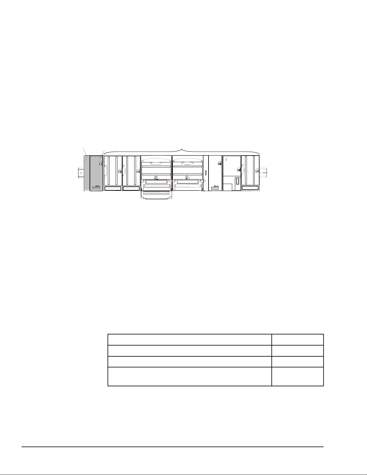
VersaMax provides automatic addressing that can eliminate traditional configuration and
VersaMax PLC CPU
power supply
VersaMax Modules
the need for hand-held devices. Multiple field wiring termination options provide support
for two, three, and four-wire devices.
For faster equipment repair and shorter Mean-Time-To-Repair, the hot insertion feature
enables addition and replacement of I/O modules while a machine or process is running
and without affecting field wiring.
VersaMax I/O may be remotely located. Remote I/O interfaces for Genius, DeviceNet,
Profibus, and Ethernet are available.
1.2 CPU Modules for VersaMax PLCs
A VersaMax PLC consists of a group of VersaMax modules with a VersaMax CPU and
attached power supply in the first position.
All VersaMax CPUs provide powerful PLC functionality. They are designed to serve as
the system controller for up to 64 modules with up to 2048 I/O points. Two serial ports
provide RS-232 and RS-485 interfaces for SNP slave and RTU slave communications.
CPU model IC200CPUE05 provides a built-in Ethernet port.
1.2.1 Basic CPU Features
• Programming in Ladder Diagram, Sequential Function Chart, and Instruction List
• Floating point (real) data functions
• Non-volatile flash memory for program storage
• Run/Stop switch
• Embedded RS-232 and RS-485 communications
• Compatible with EZ Program Store device
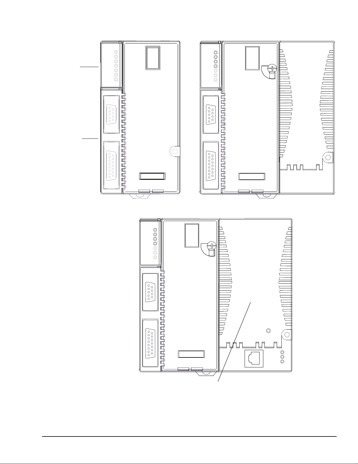
1.2.2 Available VersaMax CPUs
CPU with Two Serial Ports, 34kB of Configurable Memory IC200CPU001
CPU with Two Serial Ports, 42kB of Configurable Memory IC200CPU002
CPU with Two Serial Ports, 128kB of Configurable Memory IC200CPU005
CPU with Two Serial Ports and Embedded Ethernet Interface,
128kB of Configurable Memory
IC200CPUE05
18 GFK-1503E VersaMax PLC User Manual
For public disclosure
Page 19
RS485
PORT 2
RS232
PORT 1
CPU001
PORT 2
FORCE
PORT 1
FAULT
RUN
PWR
OK
RS485
PORT 2
RS232
PORT 1
CPU005
FAULT
RUN
PWR
OK
PORT 2
FORCE
PORT 1
CPU001
CPU002
CPU005
Status LEDs
Serial Ports
RS485
PORT 2
RS232
PORT 1
CPUE05
FAULT
RUN
PWR
OK
PORT 2
FORCE
PORT 1
PORT 1
LAN
STAT
ETHERNET
10 BASE T /
100 BASE TX
ETHERNET
RESTART
CPUE05
Ethernet Interface
Introduction GFK-1503E User Manual 19
For public disclosure
Page 20

1.2.3 EZ Program Store
PLC
IC200PWR001
VDC
+
INPUT
-
24 VDC
POWER SUPPLY
NOT
USED
The EZ Program Store device (IC200ACC003) can be used to store and update the
configuration, application program, and reference table data of a VersaMax PLC. A
programmer and PLC CPU are used to initially write data to the device.
1.3 Power Supplies
An AC or DC Power Supply provides +5V and +3.3V power to the modules in the rack.
Additional power supplies can be installed on special booster carriers if needed for
systems where the number of modules creates the need for a booster. The AC or DC
Power Supply on the CPU or NIU and the Power Supply that resides on the Booster
Carrier must share the same external power source.
CPU models IC200CPU005 and IC200CPUE05 require the use of an expanded 3.3V
power supply. Refer to the following table.
20 GFK-1503E VersaMax PLC User Manual
For public disclosure
Page 21
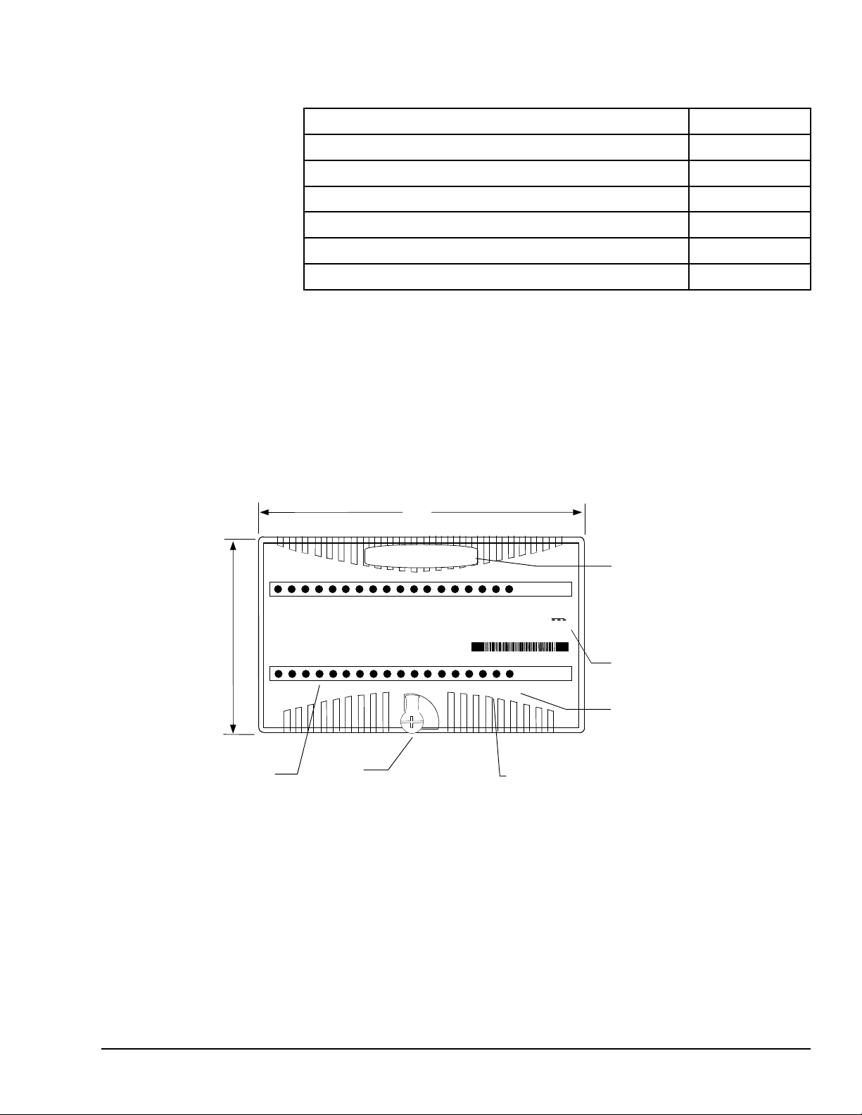
1.4 I/O Modules
66.8mm
(2.63in)
110mm
(4.33in)
Latch
Individual Point LEDS on Discrete Modules
Fie
ld Power LED indicates presence of power from external supply
OK LED indicates presence of power from VersaMax power supply
Color code:
Red: AC
Blue: DC
Gold: Mixed
Gray: Analog/other
Module Description
1234567 831
FLD
PWR
OK
IC200MDL750
OUTPUT 12/24VDC
POS GRP .5A 32PT
OK
FLD
PWR
1 2 3 4 5 6 7 8 9 10 11 12 13 14 15 16
Q
Q
17 18 19
20
21 22 23 24 25 26 27 28 29 30 31 32
1.3.1 Available Power Supplies and Carrier
The following VersaMax power supplies and carrier are available:
24VDC Power Supply IC200PWR001
24VDC Expanded 3.3V Power Supply IC200PWR002
120/240VAC Power Supply IC200PWR101
120/240VAC Expanded 3.3V Power Supply IC200PWR102
12VDC Power Supply IC200PWR201
12VDC Expanded 3.3V Power Supply IC200PWR202
Power Supply Booster Carrier IC200PWB001
Power supplies are described in the VersaMax Modules, Power Supplies, and Carriers
User Manual (GFK-1504).
VersaMax I/O and option modules are approximately 110mm (4.33in) by 66.8mm
(2.63in) in size. Modules can be mounted either horizontally or vertically on several types
of available I/O Carriers. Modules are 50mm (1.956 in) in depth, not including the height
of the carrier or the mating connectors.
Introduction GFK-1503E User Manual 21
For public disclosure
VersaMax I/O modules are described in the VersaMax Modules, Power Supplies, and
Carriers User’s Manual (GFK-1504).
Page 22

Discrete Input Modules
1.4.1 Available I/O Modules
The following types of VersaMax I/O Modules are available:
Input 120VAC 8 Point Grouped Module
Input 240VAC 8 Point Grouped Module
Input 120VAC 8 Point Isolated Module
Input 240VAC 4 Point Isolated Module
Input 120VAC (2 Groups of 8) 16 Point Module
Input 240VAC (2 Groups of 8) 16 Point Module
Input 120VAC 16 Point Isolated Module
Input 240VAC 8 Point Isolated Module
Input 125VDC Positive/Negative Logic Grouped 8 Point Module
Input 125VDC Positive/Negative Logic Grouped 16 Point Module
Input 48VDC Positive/Negative Logic Grouped 16 Point Module
Input 48VDC Positive/Negative Logic Grouped 32 Point Module
Input 24VDC Positive/Negative Logic (2 Groups of 8) 16 Point Module
Input 5/12VDC (TTL) Positive/Negative Logic 16 Point Module
Input 5/12VDC (TTL) Positive/Negative Logic Grouped 32 Point Module
Input 24VDC Positive/Negative Logic (4 Groups of 8) 32 Point Module
IC200MDL140
IC200MDL141
IC200MDL143
IC200MDL144
IC200MDL240
IC200MDL241
IC200MDL243
IC200MDL244
IC200MDL631
IC200MDL632
IC200MDL635
IC200MDL636
IC200MDL640
IC200MDL643
IC200MDL644
IC200MDL650
Discrete Output Modules
Output 120VAC 0.5A per Point Isolated 8 Point Module
Output 120VAC 0.5A per Point Isolated 16 Point Module
Output 120VAC 2.0A per Point Isolated 8 Point Module
Output 24VDC Positive Logic 2.0A per Point (1 Group of 8) w/ESCP 8
Point Module,
Output 12/24VDC Positive Logic 0.5A per Point (1 Group of 16) 16 Point
Module
Output 24VDC Positive Logic 0.5A per Point (1 Group of 16) w/ESCP 16
Point Module
Output 24VDC Positive Logic 0.5A per Point (2 Groups of 16) w/ESCP 32
Point Module
Output 5/12/24VDC Negative Logic 0.5A per Point (1 Group of 16) 16 Point
Module
Output 5/12/24VDC Negative Logic 0.5A per Point (2 Groups of 16) 32
Point Module
Output 12/24VDC Positive Logic 0.5A per Point (2 Groups of 16) 32 Point
Module
Output Relay 2.0A per Point Isolated Form A 8 Point Module
IC200MDL329
IC200MDL330
IC200MDL331
IC200MDL730
IC200MDL740
IC200MDL741
IC200MDL742
IC200MDL743
IC200MDL744
IC200MDL750
IC200MDL930
Output Relay 2.0A per Point Isolated Form A 16 Point Module
22 GFK-1503E VersaMax PLC User Manual
For public disclosure
IC200MDL940
Page 23

Discrete Mixed I/O Modules
Mixed 24VDC Positive Logic Input Grouped 20 Point / Output Relay 2.0A
per Point Grouped 12 Point Module
IC200MDD840
Mixed 24VDC Positive Logic Input 20 Point / Output 12 Point / (4) High
Speed Counter, PWM, or Pulse Train Configurable Points
Mixed 16 Point Grouped Input 24VDC Pos/Neg Logic / 16 Pt Grouped
Output 24VDC Pos. Logic 0.5A w/ESCP
Mixed 24VDC Positive Logic Input Grouped 10 Point / Output Relay 2.0A
per Point 6 Point Module
Mixed 24 VDC Pos/Neg Logic Input Grouped 16 Point / Output 12/24VDC
Pos. Logic 0.5A 16 Point Module
Mixed 16 Point Grouped Input 24VDC Pos/Neg Logic / 8 Pt Relay Output
2.0A per Pt Isolated Form A
Mixed 120VAC Input 8 Point / Output Relay 2.0A per Point 8 Point Module
Mixed 240VAC Input 8 Point / Output Relay 2.0A per Point 8 Point Module
Mixed 120VAC Input 8 Point / Output 120VAC 0.5A per Point Isolated 8
Point Module
Mixed 120VAC In Isolated 8 Point / Output Relay 2.0A Isolated 8 Point
Module
Mixed 240VAC In Isolated 4 Point / Output Relay 2.0A Isolated 8 Point
Module
Analog Input Modules
IC200MDD841
IC200MDD842
IC200MDD843
IC200MDD844
IC200MDD845
IC200MDD846
IC200MDD847
IC200MDD848
IC200MDD849
IC200MDD850
Analog Input Module, 12 Bit Voltage/Current 4 Channels
Analog Input Module, 16 Bit Voltage/Current, 1500VAC Isolation, 8
Channels
Analog Input Module, 12 Bit Voltage/Current 8 Channels
Analog Input Module, 15 Bit Differential Voltage 8 Channels
Analog Input Module, 16 Bit Differential Current 8 Channels
Analog Input Module, 15 Bit Voltage 15 Channels
Analog Input Module, 15 Bit Current 15 Channels
Analog Input Module, 16 Bit RTD, 4 Channels
Analog Input Module, 16 Bit Thermocouple, 7 Channels
Analog Output Modules
Analog Output Module, 12 Bit Current, 4 Channels
Analog Output Module, 12 Bit Voltage 4 Channels. 0 to +10VDC Range
Analog Output Module, 12 Bit Voltage 4 Channels. -10 to +10VDC Range
Analog Output Module, 13 Bit Voltage 8 Channels
Analog Output Module, 12 Bit Current 8 Channels
Analog Output Module, 13 Bit Voltage 12 Channels
IC200ALG230
IC200ALG240
IC200ALG260
IC200ALG261
IC200ALG262
IC200ALG263
IC200ALG264
IC200ALG620
IC200ALG630
IC200ALG320
IC200ALG321
IC200ALG322
IC200ALG325
IC200ALG326
IC200ALG327
Analog Output Module, 12 Bit Current 12 Channels
IC200ALG328
Introduction GFK-1503E User Manual 23
For public disclosure
Page 24

Analog Output Module, 16 Bit Voltage/Current, 1500VAC Isolation, 4
Channels
Analog Mixed I/O Modules
IC200ALG331
Analog Mixed Module, Input Current 4 Channels, Output Current 2
Channels
Analog Mixed Module, 0 to +10VDC Input 4 Channels, Output 0 to +10VDC
2 Channels
Analog Mixed Module, 12 Bit -10 to +10VDC, Input 4 Channels / Output -10
to +10VDC 2 Channels
IC200ALG430
IC200ALG431
IC200ALG432
24 GFK-1503E VersaMax PLC User Manual
For public disclosure
Page 25
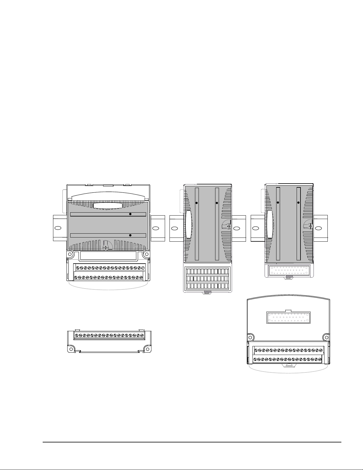
1.5 Carriers
MADE IN USA
Terminal-style I/O Carrier Compact Terminal-style
I/O Carrier
Connector-style I/O
Carrier and
Interposing Terminals
Auxiliary I/O Terminal Strip
Carriers provide mounting, backplane communications, and field wiring connections for
all types of VersaMax modules. I/O modules can be installed on carriers or removed
without disturbing field wiring.
There are three basic I/O Carrier types:
• Terminal-style I/O carriers. Modules mount parallel to the DIN rail.
• Compact Terminal-style I/O Carriers. Modules mount perpendicular to the DIN rail.
• Connector-style I/O Carriers. Modules mount perpendicular to the DIN rail. These
carriers are normally used with Interposing I/O Terminals as illustrated below.
Refer to the VersaMax Modules, Power Supplies, and Carriers User Manual (GFK-1504)
for information about VersaMax I/O Carriers.
Terminal-style I/O carriers have 36 individual terminals for direct connection of field
wiring. Auxiliary I/O Terminal Strips are available for applications requiring additional
wiring terminals.
Introduction GFK-1503E User Manual 25
For public disclosure
Page 26

Terminal-Style I/O Carriers
1.5.1 Available Carriers and Terminal Strips
The following types of Carriers, terminals, and cables are available:
Barrier-Style Terminal I/O Carrier
Box-Style Terminal I/O Carrier
Spring-Style Terminal I/O Carrier
Compact Terminal-Style I/O Carriers
Compact Box-Style I/O Carrier
Compact Spring-Style I/O Carrier
Connector-Style I/O Carrier
Connector-Style I/O Carrier
Interposing Terminals for use with Connector-Style Carrier
Barrier-Style Interposing I/O Terminals
Box-Style Interposing I/O Terminals
Thermocouple-Style Interposing I/O Terminals
Spring-Style Interposing I/O Terminals
Disconnect-Style Interposing I/O Terminals, Main Base
Disconnect-Style Interposing I/O Terminals, Expansion Base
Relay-Style Interposing I/O Terminals, Main Base
IC200CHS001
IC200CHS002
IC200CHS005
IC200CHS022
IC200CHS025
IC200CHS003
IC200CHS011
IC200CHS012
IC200CHS014
IC200CHS015
IC200CHS101
IC200CHS102
IC200CHS111
Relay-Style Interposing I/O Terminals, Expansion Base
Fuse-Style Interposing I/O Terminals, Main Base
Fuse-Style Interposing I/O Terminals, Expansion Base
Cables for use with Connector-Style I/O Carriers
2 connectors, 0.5m, no shield
2 connectors, 1.0m, no shield
2 connectors, 2.0m, no shield
1 connector, 3.0m, no shield
Auxiliary I/O Terminal Strips for use with Terminal-style I/O Carriers and Interposing Terminals
Barrier-Style Auxiliary I/O Terminal Strip
Box-Style Auxiliary I/O Terminal Strip
Spring-Style Auxiliary I/O Terminal Strip
Other Carriers
Communications Carrier IC200CHS006
Power Supply Booster Carrier
IC200CHS112
IC200CHS121
IC200CHS122
IC200CBL105
IC200CBL110
IC200CBL120
IC200CBL230
IC200TBM001
IC200TBM002
IC200TBM005
IC200PWB001
26 GFK-1503E VersaMax PLC User Manual
For public disclosure
Page 27
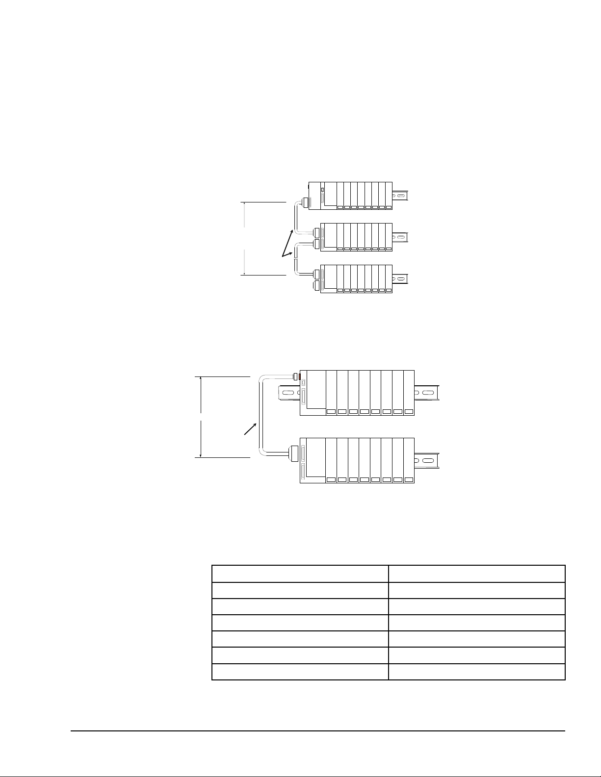
1.6 Expansion Modules
PS
CPU/NIU
PS
ERM
PS
ERM
ETM
VersaMax ExpansionRack 1
Terminator
Plug
15M with any
IC200ERM002 ERMs
750M with all
IC200ERM001 ERMs
VersaMax PLC or I/O Station Main Rack (0)
VersaMax ExpansionRack 7
IC200CBL601,
602, 615
PS
ERM
VersaMax Expansion Rack
1 M
VersaMax PLC or NIU I/O Station Main Rack
PS
CPU/NIU
IC200CBL600
There are two basic types of VersaMax I/O expansion systems, Multi-Rack and
Single-ended:
• Multi-Rack: A VersaMax PLC or NIU I/O Station with an Expansion Transmitter
Module (IC200ETM001) and one to seven expansion “racks”, each with an
Expansion Receiver Module (IC200ERM001 or IC200ERM002). If all the Expansion
Receivers are the Isolated type (IC200ERM001), the maximum overall cable length
is 750 meters. If the expansion bus includes any non-isolated Expansion Receivers
(IC200ERM002), the maximum overall cable length is 15 meters.
• Single-ended: A CPU or NIU I/O Station connected directly to one expansion rack
with non-isolated Expansion Receiver Module (IC200ERM002). Maximum cable
length is 1 meter.
1.6.1 VersaMax Modules for Expansion Racks
All types of VersaMax I/O and communications modules can be used in expansion racks.
Some VersaMax analog modules require specific module revisions as listed below:
Module Module Revision
IC200ALG320 B or later
IC200ALG321 B or later
IC200ALG322 B or later
Introduction GFK-1503E User Manual 27
For public disclosure
IC200ALG430 C or later
IC200ALG431 C or later
IC200ALG432 B or later
Page 28

1.6.2 Available Expansion Modules
The following Expansion Modules and related products are available:
Expansion Modules
Expansion Transmitter Module
Expansion Receiver Module, Isolated
Expansion Receiver Module, Non-isolated
Cables
Expansion Cable, Shielded, 1 meter
Expansion Cable, Shielded, 2 meters
Expansion Cable, Shielded, 15 meters
Firmware Update Cable
Terminator Plug (included with ETM)
Connector Kit IC200ACC302
IC200ETM001
IC200ERM001
IC200ERM002
IC200CBL601
IC200CBL602
IC200CBL615
IC200CBL002
IC200ACC201
Refer to the VersaMax Modules, Power Supplies, and Carriers User Manual (GFK-1504)
for information about VersaMax Expansion modules.
28 GFK-1503E VersaMax PLC User Manual
For public disclosure
Page 29
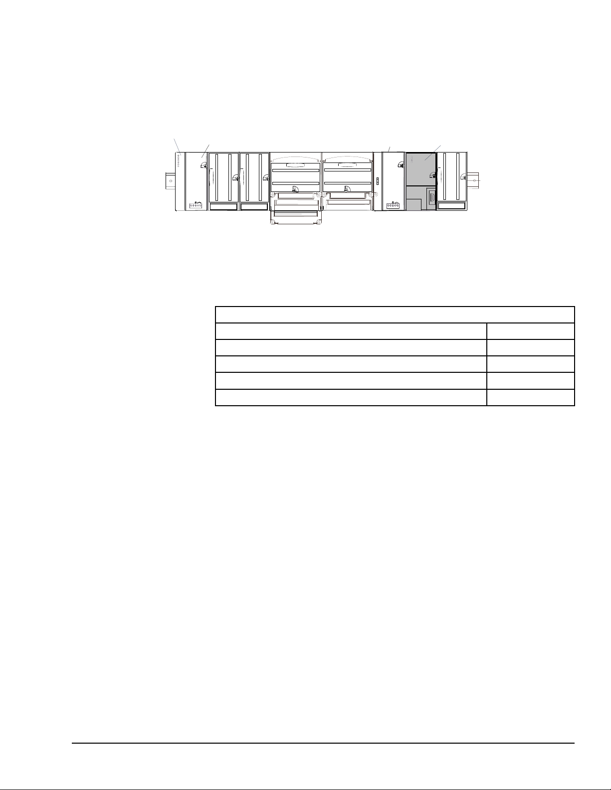
1.7 Communications Modules
VersaMax PLC CPU
power supply
Optional booster
power supply
Profibus Network
Slave Modu
le
Communications modules provide additional flexibility for VersaMax systems.
These communications modules install on a VersaMax Communications Carrier. Power
for the communications module comes from the main system power supply or from a
booster supply as shown below.
1.7.1 Available VersaMax PLC Communications
Modules
The following VersaMax PLC communications modules are available:
Communications Modules
Profibus-DP Network Slave Module IC200BEM002
DeviceNet Network Control Module IC200BEM103
Asi Network Master Module IC200BEM104
Serial Communications Module IC200CMM020
Communications Carrier IC200CHS006
For information about the Communications Carrier, refer to the VersaMax Modules,
Power Supplies, and Carriers User Manual (GFK- 1504).
1.7.2 Profibus-DP Network Slave Module
The Profibus-DP Network Slave Module (IC200BEM002) is a communications module
that exchanges PLC reference table data on the Profibus network. The VersaMax PLC
CPU can read and write this data as though it were conventional bit- and word-type I/O
data.
Multiple Profibus-DP Network Slave Modules may be used in the same VersaMax PLC.
Each one can read up to 244 bytes of data from the network, and send up to 244 bytes of
output data. The total amount of combined inputs and outputs is 384 bytes.
For information about the Profibus-DP Network Slave Module, refer to the VersaMax
System Profibus Network Modules User Manual (GFK-1534, revision A or later).
Introduction GFK-1503E User Manual 29
For public disclosure
Page 30

1.7.3 DeviceNet Network Control Module
The DeviceNet Network Control Module (IC200BEM103) is a communications module
that can be configured to operate as a master, as a slave, or as both simultaneously. It can
exchange up to 512 bytes of input data and 512 bytes of output data with other devices on
the DeviceNet network. The VersaMax PLC CPU can read and write this data as though it
were conventional bit- and word-type I/O data.
The Network Control Module operates as a Group 2 Only Client (master) and can
communicate only with Group 2 Slave devices. It can also operate as a Group 2 Only or a
UCMM-capable Server (slave), or as a master and slave simultaneously.
For information about the DeviceNet Network Control Module, refer to the VersaMax
System DeviceNet Network Communications User Manual (GFK-1533).
1.7.4 Asi Network Master Module
The VersaMax AS-Interface Network Master (IC200BEM104) conforms to the
AS-Interface Specification for the master AS-Interface protocol. It can be used to connect
a VersaMax PLC or I/O station NIU to an Actuator-Sensor network.
The AS-Interface module supports communications with up to 31 slave devices,
exchanging to exchange up to 4 bits of input data and 4 bits of output data per slave
address on the Actuator-Sensor network.
For information about the AS-Interface Network Master Module, refer to the VersaMax
System ASI Network Communications User Manual (GFK-1697).
1.7.5 Serial Communications Module
The VersaMax Serial Communications Module, IC200CMM020, operates as a Modbus
RTU Master in a VersaMax I/O Station. The Serial Communications module receives
commands from a remote host such as an RX7i PLC.
30 GFK-1503E VersaMax PLC User Manual
For public disclosure
Page 31

2 CPU Module Datasheets: CPU001,
RS485
PORT 2
RS232
PORT 1
CPU001
PORT 2
FORCE
PORT 1
FAULT
RUN
PWR
OK
RS485
PORT 2
RS232
PORT 1
CPU005
FAULT
RUN
PWR
OK
PORT 2
FORCE
PORT 1
CPU001, CPU002
CPU005
IC200CPU001
IC200CPU005
CPU002, CPU005
This chapter describes the appearance, features, and functionality of the following
VersaMax PLC CPU modules:
• IC200CPU001 CPU with 34kB configurable memory
• IC200CPU002 CPU with 42kB configurable memory
• IC200CPU005 CPU with 128kB configurable memory
VersaMax PLC CPUs IC200CPU001, CPU002, and CPU005 provide powerful PLC
functionality in a small, versatile system. They are designed to serve as the system
controller for up to 64 modules with up to 2048 I/O points. Two serial ports provide
RS-232 and RS-485 interfaces for SNP slave and RTU slave communications.
CPU Module Datasheets: CPU001, CPU002, CPU005 GFK-1503E User Manual 31
For public disclosure
Page 32

2.1 Features
• Non-volatile flash memory for program storage
• Programming in Ladder Diagram, Sequential Function Chart, and Instruction List
• Battery backup for program, data, and time of day clock
• Run/Stop switch
• Floating point (real) data functions
• Embedded RS-232 and RS-485 communications
• 70mm height when mounted on DIN rail with power supply
• Compatible with EZ Program Store device
2.2 Module Specifications
Size CPU001/002: 2.63” (66.8mm) x 5.04” (128mm) CPU005: 4.20” (106.7mm) x 5.04”
(128mm)
Program storage System flash, battery-backed RAM
Battery backup for program, data, and
time-of-day clock
Backplane current consumption:
IC200CPU001,
IC200CPU002
Backplane current consumption:
IC200CPU005
Floating point
Embedded communications RS-232, RS-485
Boolean execution speed CPU001, CPU002: 1.8ms/K (typical)
Realtime clock accuracy (for timer
functions)
Time of day clock accuracy 23ppm (0.0023%) or +/- 2sec/day @ 30C
†
CPU005 requires a power supply with expanded 3.3V.
Super capacitor provides power to memory for 1 hour.
Over 1 hour, backup battery protects memory contents up to 6 months.
Backup battery has shelf life of 5 years when not in use.
no serial port converter or EZ
Program Store device
with serial port converter or EZ
Program Store device
no serial port converter or EZ
Program Store device
with serial port converter or EZ
Program Store device
yes
CPU005: 0.5ms/K (typical)
100ppm (0.01%) or +/- 9sec/day
100 ppm (0.01%) or +/- 9sec/day @ full temperature range
5V output:
40mA
5V output:
140mA
5V output:
35mA
5V output:
135mA
3.3V output:
100mA
3.3V output:
†
300mA
32 GFK-1503E VersaMax PLC User Manual
For public disclosure
Page 33

2.3 VersaMax General Product Specifications
VersaMax products should be installed and used in conformance with product-specific
guidelines as well as the following specifications:
Environmental
Vibration IEC68-2-6
1G @57-150Hz, 0.012in p–p @10-57Hz
Shock IEC68-2-27
Operating Temp. 0 deg C to +60 deg C ambient
Storage Temp. -40 deg C to +85 deg C
Humidity 5% to 95%, noncondensing
Enclosure Protection IEC529
EMC Emission
CISPR 11/EN 55011
Radiated, Conducted
EMC Immunity
Electrostatic Discharge
RF Susceptibility
CISPR 22/EN 55022
FCC 47 CFR 15
EN 61000-4-2
EN 61000-4-3
ENV 50140/ENV 50204
15G, 11ms
Steel cabinet per IP54:
protection from dust & splashing water
Industrial Scientific & Medical Equipment
(Group 1, Class A)
Information Technology Equipment (Class A)
referred to as FCC part 15,
Radio Devices (Class A)
8KV Air, 4KV Contact
10Vrms /m, 80Mhz to 1000Mhz, 80% AM
10Vrms/m, 900MHz +/-5MHZ
100%AM with 200Hz square wave
Fast Transient Burst EN 61000-4-4
ANSI/IEEE C37.90a
Surge Withstand
Conducted RF EN 61000-4-6
Isolation
Dielectric Withstand
Power Supply
Input Dips, Variations
IEC255-4
EN 61000-4-5
UL508, UL840, IEC664
EN 61000-4-11
2KV: power supplies, 1KV: I/O, communication
Damped Oscillatory Wave: 2.5KV power supplies,
I/O [12V-240V]; 1KV communication
Damped Oscillatory Wave: Class II,
power supplies, I/O [12V-240V]
2 kV cm(P/S); 1 kV cm (I/O and communication
modules)
10Vrms, 0.15 to 80Mhz, 80%AM
1.5KV
During Operation: Dips to 30% and 100%, Variation
for AC +/-10%, Variation for DC +/-20%
CPU Module Datasheets: CPU001, CPU002, CPU005 GFK-1503E User Manual 33
For public disclosure
Page 34

2.4 Serial Ports
RS485
PORT 2
RS232
PORT 1
The two serial ports are software-configurable for SNP slave or RTU master or slave
operation. 4-wire and 2-wire RTU are supported. If a port is being used for RTU, it
automatically switches to SNP slave mode if necessary. Both ports default to SNP slave
and both automatically revert to SNP slave when the CPU is in Stop mode, if configured
for Serial I/O. Either port can be software-configured to set up communications between
the CPU and various serial devices. An external device can obtain power from Port 2 if it
requires 100mA or less at 5VDC.
Port 1: is an RS-232 port with a 9-pin female D-sub connector. The
pinout of Port 1 allows a simple straight-through cable to connect with a
standard AT-style RS-232 port. Maximum cable lengths from the CPU
to the last device attached to the cable are:
Baud Rate Maximum Cable Length
19.2 K and below 15 meters (50 ft.)
38.4K 7.5 meters (25 ft.)
57.6K 5 meters (16 ft.)
115.2K 2.5 meters (8 ft.)
Port 2: is an RS-485 port with a 15-pin female D-sub connector. This
can be attached directly to an RS-485 to RS-232 adapter
(IC690ACC901). Maximum cable lengthsfrom the CPU to the last
device attached to the cable is Port 2 1200 meters (4000 ft.)
The following table compares the functions of Port 1 and Port 2.
Port 1 Port 2
CPU Protocols (SNP slave,
RTU master/slave, Serial I/O)
Firmware Upgrade PLC in Stop/No I/O mode No
Smart module firmware
upgrade
Defaults to SNP slave Defaults to SNP slave
PLC in Stop/No I/O mode PLC in Stop/No IO mode
34 GFK-1503E VersaMax PLC User Manual
For public disclosure
Page 35

2.4.1 Serial Port Baud Rates
RUN/ON
STOP/OFF
†
, 57.6K
†
, 57.6K
††
†
†
CPU001, CPU002 CPU005
RTU protocol 1200, 2400, 4800, 9600,
19.2K
Serial I/O protocol 1200, 2400, 4800, 9600,
19.2K
1200, 2400, 4800, 9600,
19.2K, 38.4K
1200, 2400, 4800, 9600,
19.2K, 38.4K
SNP protocol 4800, 9600, 19.2K, 38.4K* 4800, 9600, 19.2K, 38.4K
Firmware Upgrade via
WinLoader
1200, 2400, 4800, 9600,
19.2K, 38.4K
1200, 2400, 4800, 9600,
19.2K, 38.4K, 57.6K,
115.2K
†
Only on one port at a time, not available on older CPU001 and CPU002 hardware
revisions.
††
Some versions of VersaPro software allow configuration of RTU and Serial I/O at
115.2K baud for CPU005. However, this baud rate is not supported by the CPU. If a
configuration using this baud rate is stored to the PLC:
1. For RTU, an Unsupported Feature in Configuration fault is logged and the PLC
transitions to Stop Faulted mode.
2. For Serial I/O, the same fault is logged when the transition to Run mode occurs. The
PLC will immediately transition to Stop Faulted mode.
†
2.5 Mode Switch
The CPU module has a convenient switch that can be used to place the PLC in Stop or
Run mode. The same switch can also be used to block accidental writing to CPU memory
and forcing or overriding discrete data. Use of this feature is configurable.
The default configuration enables Run/Stop mode selection and disables memory
protection.
CPU Module Datasheets: CPU001, CPU002, CPU005 GFK-1503E User Manual 35
For public disclosure
Page 36

2.6 CPU LEDs
CPU001
FAULT
RUN
PWR
OK
PORT 2
FORCE
PORT 1
The seven CPU LEDs, visible through the module door, indicate the presence of power
and show the operating mode and diagnostic status of the CPU. They also indicate the
presence of faults, forces, and communications on the CPU’s two ports
ON when the CPU is receiving 5V power from the power
POWER
OK
RUN
FAULT
FORCE ON if an override is active on a bit reference.
PORT 1
PORT 2
supply. Does not indicate the status of the 3.3V power
output.
ON indicates the CPU has passed its powerup diagnostics
and is functioning properly. OFF indicates a CPU problem.
Fast blinking indicates that the CPU is running its powerup
diagnostics. Slow blinking indicates the CPU is configuring
I/O modules. Simultaneous blinking of this LED and the
green Run LED indicates that the CPU is in boot mode
and is waiting for a firmware update through port 1.
Green when the CPU is in Run mode. Amber when the
CPU is in Stop/IO Scan mode. If this LED is OFF but OK is
ON, the CPU is in Stop/No IO Scan mode.
If this LED is flashing green and the Fault LED is ON, the
module switch was moved from Stop to Run mode while a
fatal fault existed. Toggling the switch will continue to Run
mode.
ON if the CPU is in Stop/Faulted mode because a fatal
fault has occurred. To turn off the Fault LED, clear both the
I/O Fault Table and the PLC Fault Table. If this LED is
blinking and the OK LED is OFF, a fatal fault was detected
during PLC powerup diagnostics. Contact PLC Field
Service
Blinking indicates activity on that port.
36 GFK-1503E VersaMax PLC User Manual
For public disclosure
Page 37

2.7 Configurable Memory
CPU001 and CPU002 (release 2.0 or later) and CPU005 have configurable user memory.
The configurable memory is the amount of memory required for the application program,
hardware configuration, registers (%R), analog inputs (%AI), and analog outputs (%AQ).
The amount of memory allocated to the application program and hardware configuration
are automatically determined by the actual program and configuration entered from the
programmer. The rest of the configurable memory can be easily allocated to suit the
application.
Configurable memory CPU001: 34K bytes maximum
Application program size (not configurable) 128 bytes minimum
CPU001, for rel. 1.50 compatibility 2K bytes
CPU002, for rel. 1.50 compatibility 20K bytes
Hardware configuration size (not configurable) 400 bytes minimum
Registers (%R) 256 bytes minimum
CPU001/002, for rel. 1.50 compatibility 4,096 bytes
Analog Inputs (%AI) 256 bytes minimum
CPU002: 42K bytes maximum
CPU005: 128K bytes maximum
Analog Outputs (%AQ) 256 bytes minimum
CPU Module Datasheets: CPU001, CPU002, CPU005 GFK-1503E User Manual 37
For public disclosure
Page 38

Notes
38 GFK-1503E VersaMax PLC User Manual
For public disclosure
Page 39

3 CPU Module Datasheet: CPUE05
RS485
PORT 2
RS232
PORT 1
CPUE05
FAULT
RUN
PWR
OK
IC200CPUE05
CPU 40K BYTES USER MEM
PORT 2
FORCE
PORT 1
PORT 1
LAN
STAT
ETHERNET
10 MBPS BASE T
ETHERNET
RESTART
IP ADDRESS
MAC XXXXXXXXXX
This chapter describes the appearance, features, and functionality of the following
VersaMax PLC CPU module:
• IC200CPUE05: CPU with two serial ports, embedded Ethernet interface, and 128K
configurable memory
CPU IC200CPUE05 shares the basic features of the other VersaMax PLC CPUs. It
provides powerful PLC functionality in a small, versatile system. CPUE05 can serve as
the system controller for up to 64 modules with up to 2048 I/O points. Two serial ports
provide RS-232 and RS-485 interfaces for serial communications. CPUE05 also provides
a built-in Ethernet Interface. The RS-232 serial port can be configured for Local Station
manager operation to provide access to diagnostic information about the Ethernet
interface. CPUE05 has 128kB of configurable memory.
In addition, CPUE05 is compatible with the EZ Program Store device, which can be used
to write, read, update, and verify programs, configuration, and reference tables data
without a programmer or programming software.
CPU Module Datasheet: CPUE05 GFK-1503E User Manual 39
For public disclosure
Page 40

3.1 Features
• 128kB of configurable memory
• Programming in Ladder Diagram, Sequential Function Chart, and Instruction List
• Non-volatile flash memory for program storage
• Battery backup for program, data, and time of day clock
• Run/Stop switch
• Floating point (real) data functions
• Embedded RS-232 and RS-485 communications
• Embedded Ethernet interface
• 70mm height when mounted on DIN rail with power supply
40 GFK-1503E VersaMax PLC User Manual
For public disclosure
Page 41

3.2 Module Specifications
Size
Program storage System flash, battery-backed RAM
Battery backup for program, data, and
time-of-day clockl
Backplane current consumption:
IC200CPUE05
Floating point
Boolean execution speed 0.5ms/K (typical)
Realtime clock accuracy (for timer
functions)
Time of day clock accuracy
Embedded communications
Configurable memory 128K bytes maximum
4.95” (126mm) x 5.04” (128mm)
Super capacitor provides power to memory for 1 hour
Over 1 hour, backup battery protects memory contents up to 6 months.
Backup battery has shelf life of 5 years when not in use.
no serial port converter or EZ
Program Store device
with serial port converter or EZ
Program Store device
yes
100ppm (0.01%) or +/- 9sec/day
23ppm (0.0023%) or +/- 2sec/day @ 30C.
100 ppm (0.01%) or +/- 9sec/day @ full temperature range
RS-232, RS-485, Ethernet interface
5V output: 100mA
5V output: 200mA
3.3V output:
†
820mA
Ethernet Interface Specifications
Number of SRTP server connections 8
Ethernet data rate
Physical interface
WinLoader support via CPU port
Number of Ethernet Global Data
configuration-based exchanges
EGD Exchange limits
Time Synchronization NTP - client only (Supported IC200CPUE05-HK or before)
Selective Consumption of EGD
Load EGD configuration from PLC to
programmer
Remote Station Manager over UDP
Local Station Manager (RS-232) via CPU port
Configurable Advanced User Parameters
†
CPUE05 requires a power supply with expanded 3.3V.
10Mbps
10BaseT RJ45 Shielded
32
100 data ranges and 1400 bytes of data per exchange; 1200 total data ranges
across all exchanges.
yes
yes
yes
yes
CPU Module Datasheet: CPUE05 GFK-1503E User Manual 41
For public disclosure
Page 42

3.3 VersaMax General Product Specifications
VersaMax products should be installed and used in conformance with product-specific
guidelines as well as the following specifications:
Environmental
Vibration IEC60068-2-6
1G @57-150Hz, 0.012in p–p @10-57Hz
Shock IE600C68-2-27
Operating Temp. 0°C (32 °F) to +60°C (140 °F) ambient
Storage Temp. -40°C (-40 °F) to +85°C (185 °F)
Humidity 5% to 95%, noncondensing
Enclosure Protection IEC60529
EMC Emission
Radiated, Conducted
EMC Immunity
Electrostatic Discharge
RF Susceptibility
Fast Transient Burst EN 61000-4-4
CISPR 11/EN 55011
CISPR 22/EN 55022
FCC 47 CFR 15
EN 61000-4-2
EN 61000-4-3
15G, 11ms
Steel cabinet per IP54:
protection from dust & splashing water
Industrial Scientific & Medical Equipment
(Group 1, Class A)
Information Technology Equipment (Class A)
referred to as FCC part 15,
Radio Devices (Class A)
8KV Air, 4KV Contact
10Vrms /m, 80Mhz to 1000Mhz, 80% AM
2KV: power supplies, 1KV: I/O, communication
Surge Withstand
Conducted RF EN 61000-4-6
Isolation
Dielectric Withstand
Power Supply
Input Dips, Variations
ANSI/IEEE C37.90a
EN 61000-4-18
IEC60255-4
EN 61000-4-5
UL508, UL840,
IEC664
EN 61000-4-11
Damped Oscillatory Wave: 2.5KV power supplies,
I/O [12V-240V]; 1KV communication
Damped Oscillatory Wave: Class II,
power supplies, I/O [12V-240V]
2 kV cm(P/S); 1 kV cm (I/O and communication modules)
10Vrms, 0.15 to 80Mhz, 80%AM
1.5KV
During Operation: Dips to 30% and 100%, Variation for AC
+/-10%, Variation for DC +/-20%
42 GFK-1503E VersaMax PLC User Manual
For public disclosure
Page 43

3.4 Serial Ports
RS485
PORT 2
RS232
PORT 1
The two serial ports are software-configurable for SNP slave or RTU master or slave
operation. 4-wire and 2-wire RTU are supported. If a port is being used for RTU, it
automatically switches to SNP slave mode if necessary. Port 1 can also be configured for
Local Station Manager operation to provide access to diagnostic information about the
Ethernet interface. Both ports default to SNP slave and both automatically revert to SNP
slave when the CPU is in Stop mode, if configured for Serial I/O. Either port can be
software-configured to set up communications between the CPU and various serial
devices. An external device can obtain power from Port 2 if it requires 100mA or less at
5VDC.
Port 1: is an RS-232 port with a 9-pin female D-sub connector. The
pinout of Port 1 allows a simple straight-through cable to connect with a
standard AT-style RS-232 port.
Port 1 can be configured for either CPU serial communications (SNP,
RTU, Serial I/O), or local Station Manager use. If Port 1 has been
configured for CPU use, it can be forced to local Station Manager
operation using the Restart pushbutton. Once forced, Port 1 remains
available for station manager use until the PLC is power cycled, or the
Restart pushbutton is pressed. If Port 1 is configured as a local Station
Manager, it cannot be used for CPU serial communications or for
firmware upgrades using Winloader. The Restart pushbutton will NOT
toggle it to the CPU serial protocols.
Port 2: is an RS-485 port with a 15-pin female D-sub connector. This
can be attached directly to an RS-485 to RS-232 adapter
(IC690ACC901). Port 2 can be used for program, configuration, and
table updates with the EZ Program Store module.
The following table compares the functions of Port 1 and Port 2.
Port 1 Port 2
CPU Protocols (SNP slave,
RTU master/slave, Serial I/O)
Local Station Manager Yes (see above) No
Firmware Upgrade PLC in Stop/No I/O
Smart module firmware
upgrade
EZ Program Store device No Read, Write, Verify, and
Defaults to SNP slave Defaults to SNP slave
No
mode, Port 1 not disabled
or in Local Station
Manager mode.
PLC in Stop/No I/O
mode, Port 1 configured
PLC must be in Stop/No
IO mode.
for CPU protocol
Update. PLC must be in
Stop/No IO mode.
CPU Module Datasheet: CPUE05 GFK-1503E User Manual 43
For public disclosure
Page 44

3.4.1 Cable Lengths
Maximum cable lengths from the CPU to the last device attached to the cable are:
Port 1 (RS-232):
Baud Rate
Maximum Cable Length
19.2 K and below 15 meters (50 ft.)
38.4K 7.5 meters (25 ft.)
57.6K 5 meters (16 ft.)
115.2K 2.5 meters (8 ft.)
Port 2 (RS-485): 1200 meters (4000 ft.)
3.4.2 Serial Port Baud Rates
Port 1 Port 2
RTU protocol 1200, 2400, 4800, 9600,
19.2K, 38.4K
Serial I/O protocol 1200, 2400, 4800, 9600,
19.2K, 38.4K
SNP protocol 4800, 9600, 19.2K,
38.4K
Local Station Manager (this is
independent of serial protocol
baud rate)
1200, 2400, 4800, 9600,
19.2K, 38.4K, 57.6K,
115.2K
†
, 57.6K
†
, 57.6K
†
1200, 2400, 4800, 9600,
†
19.2K, 38.4K
1200, 2400, 4800, 9600,
†
19.2K, 38.4K
4800, 9600, 19.2K,
†
38.4K
NA
†
, 57.6K
†
, 57.6K
†
†
Firmware Upgrade via
WinLoader
†
Only on one port at a time.
2400, 4800, 9600, 19.2K,
38.4K, 57.6K, 115.2K
NA
Some versions of VersaPro software allow configuration of RTU and Serial I/O at 115.2K
baud. However, this baud rate is not supported by the CPU. If a configuration using this
baud rate is stored to the PLC:
1. For RTU, an Unsupported Feature in Configuration fault is logged and the PLC
transitions to Stop Faulted mode.
2. For Serial I/O, the same fault is logged when the transition to Run mode occurs. The
PLC will immediately transition to Stop Faulted mode.
44 GFK-1503E VersaMax PLC User Manual
For public disclosure
Page 45

3.5 Ethernet LAN Port
PORT 1
LAN
STAT
ETHERNET
10 BASE T
ETHERNET
RESTART
Ethernet
LAN Port
RJ 45
IP ADDRESS
IP Address
Writable Area
RUN/ON
STOP/OFF
The Ethernet LAN port supports SRTP Server and Ethernet Global Data. This port
connects directly to a 10BaseT (twisted pair shielded) network without an external
transceiver. The 10BaseT twisted pair shielded cables must meet applicable IEEE 802
standards. CPUE05 automatically selects either half-duplex or full duplex operation, as
sensed from the network connection.
A space is provided on the front of the CPUE05 module where the configured IP Address
can be written.
3.6 Mode Switch
The Mode switch is located behind the module door. It can be used to place the PLC in
Stop or Run mode. It can also be used to block accidental writing to CPU memory and
forcing or overriding discrete data. Use of this feature is configurable. The default
configuration enables Run/Stop mode selection and disables memory protection.
CPU Module Datasheet: CPUE05 GFK-1503E User Manual 45
For public disclosure
Page 46

3.7 CPU LEDs
CPUE05
FAULT
RUN
PWR
OK
PORT 2
FORCE
PORT 1
The seven CPU LEDs, visible through the module door, indicate the presence of power
and show the operating mode and diagnostic status of the CPU. They also indicate the
presence of faults, forces, and communications on the CPU’s two ports
ON when the CPU is receiving 5V power from the power
POWER
OK
RUN
FAULT
FORCE ON if an override is active on a bit reference.
PORT 1
PORT 2
supply. Does not indicate the status of the 3.3V power
output.
ON indicates the CPU has passed its powerup diagnostics
and is functioning properly. OFF indicates a CPU problem.
Fast blinking indicates that the CPU is running its powerup
diagnostics. Slow blinking indicates the CPU is configuring
I/O modules. Simultaneous blinking of this LED and the
green Run LED indicates that the CPU is in boot mode
and is waiting for a firmware update through port 1.
Green when the CPU is in Run mode. Amber when the
CPU is in Stop/IO Scan mode.
If this LED is OFF but OK is ON, the CPU is in Stop/No IO
Scan mode. If this LED is flashing green and the Fault
LED is ON, the module switch was moved from Stop to
Run mode while a fatal fault existed. Toggling the switch
will continue to Run mode.
ON if the CPU is in Stop/Faulted mode because a fatal
fault has occurred. To turn off the Fault LED, clear both the
I/O Fault Table and the PLC Fault Table. If this LED is
blinking and the OK LED is OFF a fatal fault was detected
during PLC powerup diagnostics. Contact PLC Field
Service
Blinking indicates activity on that port when controlled by
the CPU.
46 GFK-1503E VersaMax PLC User Manual
For public disclosure
Page 47

3.8 Ethernet Restart Pushbutton
PORT 1
LAN
STAT
ETHERNET
10 BASE T
ETHERNET
RESTART
Ethernet Restart
Pushbutton
Ethernet
LEDs
IP ADDRESS
IP Address
Writable Area
The Ethernet Restart pushbutton is located on the right side of the module.
The Ethernet Restart pushbutton has two functions:
• When pressed for less than 5 seconds, it resets the Ethernet hardware, tests the
Ethernet LEDs, and restarts the Ethernet firmware. This disrupts any Ethernet
communications that are presently underway.
• When pressed for at least 5 seconds, it toggles the function of Port 1 between its
configured operation and forced local Station Manager operation. Note that if Port 1
is available for Local Station Manager operation, Winloader cannot be used for a
firmware upgrade.
3.9 Ethernet LEDs
Three LEDs indicate the status and activity of the Ethernet interface.
LAN indicates the status and activity of the Ethernet network connection. ON/blinking
green indicates Ethernet interface is online.
STAT indicates the general status of the Ethernet interface. ON green indicates no
exception detected. ON amber indicates an exception. Blinking amber indicates error
code. Blinking green indicates waiting for configuration or waiting for IP address.
PORT1 indicates when the Ethernet interface is controlling the RS-232 serial port. It
also indicates when the Ethernet Restart pushbutton has been used to override configured
RS-232 port usage for Local Station Manager operation. ON amber indicates Port 1 is
available for Local Station Manager use (either by configuration or forced). OFF indicates
PLC CPU is controlling Port 1. (Does not blink to indicate traffic).
The Ethernet LEDs turn ON briefly (green) when a restart is performed in the Operational
state by pressing and releasing the Restart pushbutton. This verifies that the Ethernet
LEDs are operational. All three LEDs blink green in unison when a software load is in
progress.
CPU Module Datasheet: CPUE05 GFK-1503E User Manual 47
For public disclosure
Page 48

3.10 Configurable Memory
CPUE05 provides a total of 128K bytes of configurable user memory. This 64K of
memory is use for the application program, hardware configuration, registers (%R),
analog inputs (%AI), and analog outputs (%AQ). The amount of memory allocated to the
application program and hardware configuration are automatically determined by the
actual program and configuration entered from the programmer. The rest of the 64K bytes
can be easily configured to suit the application.
Configurable memory 128K bytes maximum
Application program size (not configurable) 128 bytes minimum
Hardware configuration size (not
configurable)
Registers (%R) 256 bytes minimum
Analog Inputs (%AI) 256 bytes minimum
Analog Outputs (%AQ) 256 bytes minimum
528 bytes minimum
48 GFK-1503E VersaMax PLC User Manual
For public disclosure
Page 49

3.11 Ethernet Interface Overview
CPUE05 has a built-in Ethernet interface that makes it possible to communicate on a
10BaseT network. Both half-duplex and full-duplex operation are supported. Using
10/100 hubs allows CPUE05 to communicate on a network containing 100Mb devices.
3.11.1 SRTP Server
CPUE05 supports up to eight simultaneous SRTP Server connections for use by other
devices on the Ethernet network, such as the PLC programmer, CIMPLICITY HMI,
SRTP channels for Series 90 PLCs, and Host Communications Toolkit applications. No
PLC programming is required for server operation.
3.11.2 Ethernet Global Data
CPUE05 supports up to 32 simultaneous Ethernet Global Data exchanges. Global Data
exchanges are configured using the PLC programming software, then stored to the PLC.
Both Produced and Consumed exchanges may be configured. CPUE05 supports up to
1200 variables across all Ethernet Global Data exchanges, and supports selective
consumption of Ethernet Global Data exchanges. Refer to chapter 13 for information
about Ethernet Global Data.
3.11.3 Station Manager Functionality
CPUE05 has built-in Station Manager functionality. This permits on-line diagnostic and
supervisory access through either the Station Manager port or via the Ethernet network.
Station Manager services include:
• An interactive set of commands for interrogating and controlling the station.
• Unrestricted access to observe internal statistics, an exception log, and configuration
parameters.
• Password security for commands that change station parameters or operation.
Use of the Station Manager function requires a separate computer terminal or terminal
emulator.
Refer to the VersaMax PLC Ethernet Station Manager Manual (GFK-1876) for
information about Station Manager operation.
CPU Module Datasheet: CPUE05 GFK-1503E User Manual 49
For public disclosure
Page 50

Notes
50 GFK-1503E VersaMax PLC User Manual
For public disclosure
Page 51

4 Installation
This chapter describes:
• Installing the CPU
• Installing the power supply
• Installing additional modules
• Activating or replacing the backup battery
• Serial port connections
• Installing expansion modules
• Ethernet connection for CPUE05
• CE Mark installation requirements
System installation instructions, which give guidelines for carrier, power supply, and
module installation, as well as information about field wiring and grounding, are located
in the VersaMax Modules, Power Supplies, and Carriers Manual (GFK-1504).
Installation GFK-1503E User Manual 51
For public disclosure
Page 52

4.1 Mounting Instructions
All VersaMax modules and carriers in the same PLC “rack” must be installed on a single
section of 7.5mm X 35mm DIN rail, 1mm thick. Steel DIN rail is recommended. The
DIN rail must be electrically grounded to provide EMC protection. The rail must have a
conductive (unpainted) corrosion-resistant finish. DIN rails compliant with DIN EN50022
are preferred. For vibration resistance, the DIN rail should be installed on a panel using
screws spaced approximately 15.24cm (6 inches) apart.
The base snaps easily onto the DIN rail. No tools are required for mounting or grounding
to the rail.
4.1.1 Removing the CPU from the DIN Rail
1. Turn off power to the power supply.
2. (If the CPU is attached to the panel with a screw) remove the power supply module.
Remove the panel-mount screw.
3. Slide the CPU along the DIN rail away from the other modules until the connector
disengages.
4. With a small flathead screwdriver, pull down on the DIN rail latch tab(s) on the
bottom of the module and lift the module off the DIN rail.
4.1.2 Panel-mounting
For maximum resistance to mechanical vibration and shock, the equipment must also be
installed on a panel. Using the module as a template, mark the location of the module’s
panel-mount hole on the panel. Drill the hole in the panel. Install the module using an
M3.5 (#6) screw in the panel-mount hole.
52 GFK-1503E VersaMax PLC User Manual
For public disclosure
Page 53

Note 1. Tolerances on all dimensions are +/- 0.13mm +/-0.005in) noncumulative.
SEE NOTE 2.
M3.5 (#6) SCREW
15.9mm
0.62in REF
SPLIT LOCK
WASHER
FLAT WASHER
CPU
TAPPED
HOLE IN
PANEL
5.1mm
0.200in
4.3mm
0.170in
4.3mm
0.170in
Note 2. Apply 1.1 to 1.4Nm (10 to 12 in/lbs) of torque to the M3.5 (#6-32) steel screw
threaded into material containing internal threads and having a minimum thickness of
2.4mm (0.093in).
Installation GFK-1503E User Manual 53
For public disclosure
Page 54

4.2 Installing an Expansion Transmitter Module
PS
CPU
ETM
VersaMax PLC Main Rack (0)
Expansion Transmitter Module
CPU and Power Supply
PWR
EXP TX
On indicates presence of 5VDC power.
Off indicates no 5VDC power.
Blinking or On indicates active
communications on expansion bus.
Off indicates no communications.
If the VersaMax PLC will have more than one expansion rack or one expansion rack that
uses an Isolated Expansion Receiver Module (IC200ERM001) as its interface to the
expansion bus, an Expansion Transmitter Module must be installed to the left of the CPU.
The Expansion Transmitter Module must be installed on the same section of DIN rail as
the rest of the modules in the main rack (rack 0).
1. Make sure rack power is off.
2. Attach the Expansion Transmitter to DIN rail to the left of the CPU position.
3. Install the CPU. Connect the modules and press them together until the connectors
are mated.
4. After completing any additional system installation steps, apply power and observe
the module LEDs.
54 GFK-1503E VersaMax PLC User Manual
For public disclosure
4.2.1 Removing an Expansion Transmitter Module
1. Make sure rack power is off.
2. Slide module on DIN rail away from the CPU in the main rack.
3. Using a small screwdriver, pull down on the tab on the bottom of the module and lift
the module off the DIN rail.
Page 55

4.3 Installing an Expansion Receiver Module
5
7
6
4
1
3
2
PWR
EXP RX
SCAN
On indicates presence of 5VDC power.
Off indicates no 5VDC power.
Blinking or On indicates module is
communicating on expansion bus
Off indicates module not communicating
Green indicates CPU/NIU is scanning
I/O in expansion racks.
Amber indicates not scanning.
An Expansion Receiver Module (IC200ERM001 or 002) must be installed in the leftmost
slot of each VersaMax expansion rack.
1. Insert the label inside the small access door at the upper left corner of the module.
2. Attach the module to the DIN rail at the left end of the expansion rack.
3. Select the expansion rack ID (1 to 7) using the rotary switch under the access door at
upper left corner of the module. Each rack must be set to a different rack ID. With a
single-ended cable (one expansion rack only), set the Rack ID to 1.
4. Install a VersaMax Power Supply module on top of the Expansion Receiver. Refer to
the section, Installing Power Supply Modules in this chapter for details.
5. Attach the cables. If the system includes an Expansion Transmitter Module, attach
the terminator plug to the EXP2 port on the last Expansion Receiver Module.
6. After completing any additional system installation steps, apply power and observe
the module LEDs.
4.3.1 Removing an Expansion Receiver Module
1. Make sure rack power is off.
2. Uninstall the Power Supply module from the Expansion Receiver Module.
3. Slide the Expansion Receiver Module on DIN rail away from the other modules.
4. Using a small screwdriver, pull down on the tab on the bottom of the module and lift
the module off the DIN rail.
4.3.2 Expansion Rack Power Sources
Power for module operation comes from the Power Supply installed on the Expansion
Receiver Module. If the expansion rack includes any Power Supply Booster Carrier and
additional rack Power Supply, it must be tied to the same source as the Power Supply on
the Expansion Receiver Module.
Installation GFK-1503E User Manual 55
For public disclosure
Page 56

4.3.3 Connecting the Expansion Cable: RS-485
PS
CPU/NIU
PS
ERM
PS
ERM
ETM
VersaMax ExpansionRack 1
Terminator
Plug
15M with any
IC200ERM002 ERMs
750M with all
IC200ERM001 ERMs
VersaMax PLC or I/O Station Main Rack (0)
VersaMax ExpansionRack 7
Expansion
Transmitter or
Expansion
Receiver
Module
Transmitting
Port
PIN
2
3
5
6
8
9
12
13
16
17
20
21
24
25
7
23
1
FRAME+
FRAME-
RIRQ/+
RIRQ/RUN+
RUNRERR+
RERR
-
IODT+
IODT
-
RSEL+
RSELIOCLK+
IOCLK0V
0V
SHIELD
PIN
2
3
5
6
8
9
12
13
16
17
20
21
24
25
7
23
1
FRAME+
FRAME-
RIRQ/+
RIRQ/RUN+
RUNRERR+
RERR
-
IODT+
IODT
-
RSEL+
RSELIOCLK+
IOCLK0V
0V
SHIELD
26-PIN
FEMALE
26-PIN
MALE
26-PIN
MALE
26-PIN
FEMALE
VARIABLE (SEE
TEXT)
Expansion
Transmitter
or
Expansion
Receiver
Module
Receiving
Port
Differential
For a multiple-rack expansion system, connect the cable from the expansion port on the
Expansion Transmitter to the Expansion Receivers as shown below. If all the Expansion
Receivers are the Isolated type (IC200ERM001), the maximum overall cable length is
750 meters. If the expansion bus includes any non-isolated Expansion Receivers
(IC200ERM002), the maximum overall cable length is 15 meters.
Install the Terminator Plug (supplied with the Expansion Transmitter module) into the
lower port on the last Expansion Receiver. Spare Terminator Plugs can be purchased
separately as part number IC200ACC201 (Qty 2).
56 GFK-1503E VersaMax PLC User Manual
For public disclosure
4.3.4 RS-485 Differential Inter-Rack Connection (IC200CBL601, 602, 615)
4.3.5 Building a Custom Expansion Cable
Custom expansion cables can be built using Connector Kit IC200ACC202, Crimper AMP
90800-1, and Belden 8138, Manhattan/CDT M2483, Alpha 3498C, or equivalent AWG
#28 (0.089mm
2
) cable.
Page 57

4.3.6 Connecting the Expansion Cable: Single-ended
PS
ERM
VersaMax Expansion Rack
1 M
VersaMax PLC or NIU I/O Station Main Rack
PS
CPU/NIU
PIN
1
2
3
6
9
10
12
16
14
0V
T_IOCLK
T_RUN
T_IODT_
T_RERR
T_RIRQ_
T_FRAME
T_RSEL
0V
PIN
16-PIN
MALE
16-PIN
FEMALE
26-PIN
MALE
26-PIN
FEMALE
15 16
1 2
4
7
22
14
18
15
11
10
19
23
1
SINGLE_
0V
T_IOCLK
T_RUN
T_IODT_
T_RERR
T_RIRQ_
T_FRAME
T_RSEL
0V
SHIELD
1 M
Expansion
Receiver
IC200ERM002
Receiving
Port
VersaMax
CPU or NIU
Serial Port
For a system with one non-isolated expansion rack (IC200ERM002) and NO Expansion
Transmitter, connect the expansion cable from the serial port on the VersaMax CPU to the
Expansion Receiver as shown below. The maximum cable length is one meter. Cables
cannot be fabricated for this type of installation; cable IC200CBL600 must be ordered
separately.
No Terminator Plug is needed in a single-ended installation; however, it will not impede
system operation if installed.
4.3.7 Single-ended Inter-Rack Connection
(IC200CBL600)
4.3.8 Power Sources for Single-ended Expansion
Rack Systems
Installation GFK-1503E User Manual 57
For public disclosure
When operating the system in single-ended mode, power supplies for the main rack and
expansion rack must use the same main power source. The main rack and expansion racks
cannot be switched ON and OFF separately; either both must be ON or both must be OFF
for proper operation. Power for modules in the expansion rack comes from the Power
Supply installed on the Expansion Receiver Module. If the expansion rack includes a
Power Supply Booster Carrier and additional rack Power Supply, it must be tied to the
same source as the Power Supply on the Expansion Receiver Module.
Page 58

4.4 Installing Power Supply Modules
Power Supply modules install directly onto the CPU module, Expansion Receiver
Modules, and supplementary power supply carriers.
The Power Supply on the CPU or Expansion Receiver Module supplies +5V and +3.3V to
downstream modules through the mating connector. The number of modules that can be
supported depends on the power requirements of the modules. Additional booster Power
Supplies can be used as needed to meet the power needs of all modules. If the rack
includes any Power Supply Booster Carrier and additional rack Power Supply, it must be
tied to the same source as the Power Supply on the CPU. The configuration software
provides power calculations with a valid hardware configuration. Power Supply
installation instructions are given below.
1. The latch on the power supply must be in the
unlocked position.
2. Align the connectors and the latch post and press
the power supply module down firmly, until the two
tabs on the bottom of the power supply click into
place. Be sure the tabs are fully inserted in the
holes in bottom edge of the CPU, ERM, or carrier.
3. Turn the latch to the locked position to secure the
power supply.
4.4.1 Removing the Power Supply
Exercise care when working around operating equipment. Devices may become very hot
and could cause injury.
1. Remove power.
2. Turn the latch to the unlocked position as
illustrated.
3. Press the flexible panel on the lower edge of the
power supply to disengage the tabs on the power
supply from the holes in the carrier.
4. Pull the power supply straight off.
58 GFK-1503E VersaMax PLC User Manual
For public disclosure
Page 59

4.5 Installing Additional Modules
Connector Cover
Connector Cover
A CPU or Expansion Receiver Module can serve up to 8 additional I/O and option
modules on the same section of DIN rail. Power must be off before adding a carrier to the
rack.
Before joining carriers to the CPU or ERM, remove the connector cover on the righthand
side of the CPU/ERM. Do not discard this cover; you will need to install it on the last
carrier. It protects the connector pins from damage and ESD during handling and use.
Do not remove the connector cover on the lefthand side.
Install each carrier close to the previously-installed carrier, then slide the properly-aligned
carriers together to join the mating connectors. To avoid damaging the connector pins, do
not force or slam carriers together.
DIN-rail clamps (available as part number IC200ACC313) should be installed at both
ends of the station to lock the modules in position.
Installation GFK-1503E User Manual 59
For public disclosure
Page 60

4.6 Activating or Replacing the Backup Battery
The CPU module is shipped with a battery already installed. The battery holder is located
in the top side of the CPU module. Before the first use, activate the battery by pulling and
removing the insulator tab.
4.6.1 Lithium Battery Replacement
To replace the battery, use a small screwdriver to gently pry open the battery holder.
Replace battery only with one of the following:
GE IC200ACC001
Panasonic BR2032
Use of another battery may present a risk of fire or explosion
Battery may explode if mistreated.
Caution
Do not recharge, disassemble, heat above 100°C (212 °F) or incinerate.
60 GFK-1503E VersaMax PLC User Manual
For public disclosure
Page 61

4.7 Serial Port Connections
RS485
PORT 2
1
8
RS232
PORT 1
1
5
4.7.1 Providing Power to an External Device from
Port 2
If either port is set up for communications with a serial device that requires 100mA or
less at 5VDC, the device can obtain power from Port 2.
4.7.2 Cable Lengths and Baud Rates
Maximum cable lengths (the total number of feet from the CPU to the last device attached
to the cable) are:
Port 1 (RS-232) = 15 meters (50 ft.)
Port 2 (RS-485) = 1200 meters (4000 ft.)
Both ports support configurable baud rates, as listed in the CPU descriptions in this
manual.
The following pre-assembled cables are available:
IC200CBL001 CPU Programming Cable RS232
IC200CBL002 Expansion Firmware Upgrade Cable
Installation GFK-1503E User Manual 61
For public disclosure
Page 62

4.7.3 Port 1: RS-232
2
6
7
8
9
3
4
5
2
6
7
8
9
3
4
5
1
1
The shield must connect to
shell of connectors on both
ends of the cable.
PC 9-Pin CPU
Serial Port Port 1
9-pin female 9-pin male
(2) RXD (2) TXD
(3) TXD (3) RXD
(5) GND (5) GND
(7) RTS (7) CTS
(8) CTS (8) RTS
4.7.3.1 Pin Assignments for Port 1
Port 1 is an RS-232 port with a 9-pin female D-sub connector. It is used as the boot loader
port for upgrading the CPU firmware. The pinout of Port 1 allows a simple
straight-through cable to connect with a standard AT-style RS-232 port. Cable shielding
attaches to the shell.
Pin
1 n/c
2 TXD Output Transmit Data output
3 RXD Input Receive Data input
4 n/c
5
6 n/c
7
8 RTS Output Request to Send output
9 n/c
Shell SHLD
Signal
GND
CTS Input Clear to Send input
Direction Function
–
–
0V/GND signal reference
Cable Shield wire connection / 100% (Continuous) shielding
cable shield connection
4.7.3.2 RS-232 Point-to-Point Connection
In point-to-point configuration, two devices are connected to the same communication
line. For RS-232, the maximum length is 15 meters (50ft).
62 GFK-1503E VersaMax PLC User Manual
For public disclosure
Page 63

4.7.3.3 Connector and Cable Specifications for Port 1
Vendor Part numbers below are provided for reference only. Any part that meets the same
specification can be used.
Cable:
Belden 9610
Computer cable, overall braid over foil shield
5 conductor
†
30 Volt / 80°C (176°F)
24 AWG tinned copper, 7x32 stranding
9 Pin Male
Connector:
Type:
Crimp
Vendor:
ITT/Cannon DEA9PK87F0 030-2487-017
Plug:
Pin:
AMP 205204-1 66506-9
Solder
ITT/Cannon ZDE9P
AMP 747904-2
††
Kit
– ITT Cannon DE121073-54 [9-pin size backshell kit]:
Metal-Plated Plastic (Plastic with Nickel over Copper)
–
–
†
Cable Grounding Clamp (included)
Connector
Shell:
40° cable exit design to maintain low-profile installation
Plus – ITT Cannon 250-8501-010 [Extended Jackscrew]:
Threaded with #4-40 for secure attachment to CPU001 port
Order Qty 2 for each cable shell ordered
†
Critical Information – any other part selected should meet or exceed this requirement.
†
Installation GFK-1503E User Manual 63
For public disclosure
Page 64

4.7.4 Port 2: RS-485
4.7.4.1 Pin Assignments for Port 2
Port 2 is an RS-485 port with a 15-pin female D-sub connector. This can be attached
directly to an RS-485 to RS-232 adapter.
Pin
1 SHLD
2, 3, 4 n/c
5 P5V Output +5.1VDC to power external devices
6 RTSA Output Request to Send (A) output
7
8 CTSB’ Input Clear to Send (B) input
9 RT
10 RDA’ Input Receive Data (A) input
11 RDB’ Input Receive Data (B) input
12 SDA Output Transmit Data (A) output
13 SDB Output Transmit Data (B) output
14 RTSB Output Request to Send (B) output
15 CTSA’ Input Clear to Send (A) input
Shell SHLD
Signal
GND
Direction Function
–
–
–
–
Cable Shield Drain wire connection
(100mA max.)
0V/GND reference signal
Resistor Termination (120 ohm) for RDA’
Cable Shield wire connection / 100%
(Continuous) shielding cable shield
connection
4.7.4.2 Connector and Cable Specifications for Port 2
Vendor Part numbers below are provided for reference only. Any part that meets the same
specification can be used.
Cable:
Belden 8105
15 Pin Male
Connector:
Low Capacitance Computer cable, overall braid over foil shield
5 Twisted-pairs
Shield Drain Wire
30 Volt / 80°C (176°F)
24 AWG tinned copper, 7x32 stranding
Velocity of Propagation = 78%
Nominal Impedance = 100W
Type:
Crimp
Solder
†
†
†
Vendor:
ITT/Cannon DAA15PK87F0 030-2487-017
AMP 205206-1 66506-9
ITT/Cannon ZDA15P
AMP 747908-2
Plug:
Pin:
–
–
64 GFK-1503E VersaMax PLC User Manual
For public disclosure
Page 65

Kit* – ITT Cannon DA121073-50 [15-pin size backshell kit]:
Shielded Twisted Pairs
PIN PIN
PLC
Up to 15.2 meters (50 ft) without isolation
Computer
12
13
10
11
9
6
14
8
15
3
2
7
1
SD ( A )
SD ( B )
RD ( A' )
RD ( B ' )
RT
RTS ( A )
RTS ( B )
CTS ( B' )
CTS ( A' )
GND
SHLD
RD ( A' )
RD ( B' )
SD ( A )
SD ( B )
CTS ( A' )
CTS ( B' )
RTS ( B ')
RTS ( A )
GND
SHLD
Metal-Plated Plastic (Plastic with Nickel over Copper)
Cable Grounding Clamp (included)
Connector
Shell:
†
Critical Information – any other part selected should meet or exceed this requirement.
40° cable exit design to maintain low-profile installation
Plus – ITT Cannon 250-8501-009 [Extended Jackscrew]:
Threaded with (metric) M3x0.5 for secure attachment
Order Qty 2 for each cable shell ordered
†
†
4.7.5 RS-485 Point-to-Point Connection with Handshaking
In point-to-point configuration, two devices are connected to the same communication
line. For RS-485, the maximum cable length is 1200 meters (4000 feet). Modems can be
used for longer distances.
Installation GFK-1503E User Manual 65
For public disclosure
4.7.6 RS-485 Multidrop Serial Connections
In the multidrop configuration, the host device is configured as the master and one or
more PLCs are configured as slaves. The maximum distance between the master and any
slave may not exceed 4000 feet (1200 meters). This figure assumes good quality cables
and a moderately noisy environment. A maximum of 8 slaves can be connected using
RS485 in a daisy chain or multidrop configuration. The RS485 line must include
handshaking and use wire type as specified earlier.
Page 66

Slave
Station
Last
Station
Master
When wiring RS-485 multidrop cables, reflections on the transmission line can be
PIN
2
3
12 SD(A)
13 SD(B)
10 RD(A’)
11 RD(B’)
9 RT
6 RTS(A)
14 RTS(B)
15 CTS(A’)
8 CTS(B’)
5 +5V
7 0V
1 SHLD
Power Source for Converter.
Must be wired no less than 3
meters (10 feet) from the converter.
5V
0V
15- PIN
MALE
PIN
RS-485 Cables
Make connections
inside D-connectors
TO OTHER PLC's
RS-232/RS-485
Converter
IC690ACC900
15-PIN
FEMALE
RS-485
PORT
25-PIN
FEMALE
RS-232
PORT
9-Pin Female to 25-
Pin Male RS-232
Shielded Cable
3
RD
2 TD
5 CTS
20 DTR
8 DCD
7 GND
1 SHLD
RD 2
TD 3
RTS 7
CTS 8
DCD 1
DTR 4
GND 5
PIN
PIN
9 Pin Male
Connector
Computer
RS-232 Port
DCD(A)
2
DCD(B) 3
RD(A’) 10
RD(B’) 11
SD(A) 12
SD(B) 13
RT 9
CTS(A’) 15
CTS(B’) 8
RTS(A) 6
RTS(B) 14
+5V 5
0V 7
SHLD 1
CPU
RS-485 Port
15 Pin Female
Connector
(NC)
reduced by daisy-chaining the cable as shown below. Make connections inside the
connector to be attached to the PLC. Avoid using terminal strips to other types of
connectors along the length of the transmission line.
66 GFK-1503E VersaMax PLC User Manual
For public disclosure
Termination resistance for the Receive Data (RD) signal must be connected only on units
at the ends of lines. This termination is made at the CPU by connecting a jumper between
pin 9 and pin 10 inside the D-shell connector. Ground Potential: Multiple units not
connected to the same power source must have common ground potential or ground
isolation for proper operation of the system.
Page 67

4.8 Ethernet Connection for CPUE05
10BaseT
Twisted Pair
Cable
10BaseT Hub
To
Other Network
Devices
CPUE05
Ethernet Cable
Series 90-70 PLC with
Ethernet Interface
Host Computer or Control Device
Running a Host Communications
Toolkit Application
Series 90-30 PLC with
Ethernet Interface
Programmer Software
running on a PC
VersaMax PLC with
CPUE05
VersaMax PLC with
CPUE05
Hub
The Ethernet port on PLC module IC200CPUE05 connects directly to a 10BaseT (twisted
pair shielded) network without an external transceiver. Connect the port to an external
10BaseT hub or switch or a hub or repeater with autosense of 10/100 using a twisted pair
cable. Cables are readily available from commercial distributors. GE recommends
purchasing rather than making cables. Your 10BaseT twisted pair shielded cables must
meet the applicable IEEE 802 standards.
4.8.1 Network Connection
Connection of the CPUE05 to a 10BaseT network is shown below:
The cable between each node and a hub or repeater can be up to 100 meters in length.
Typical hubs or repeaters support 4 to 12 nodes connected in a star wiring topology.
Installation GFK-1503E User Manual 67
For public disclosure
Page 68

4.9 CE Mark Installation Requirements
The following requirements for surge, electrostatic discharge (ESD), and fast transient
burst (FTB) protection must be met for applications that require CE Mark listing:
• The VersaMax PLC is considered to be open equipment and should therefore be
installed in an enclosure (IP54).
• This equipment is intended for use in typical industrial environments that utilize
anti-static materials such as concrete or wood flooring. If the equipment is used in an
environment that contains static material, such as carpets, personnel should discharge
themselves by touching a safely grounded surface before accessing the equipment.
• If the AC mains are used to provide power for I/O, these lines should be suppressed
prior to distribution to the I/O so that immunity levels for the I/O are not exceeded.
Suppression for the AC I/O power can be made using line-rated MOVs that are
connected line-to-line, as well as line-to-ground. A good high-frequency ground
connection must be made to the line-to-ground MOVs.
• AC or DC power sources less than 50V are assumed to be derived locally from the
AC mains. The length of the wires between these power sources and the PLC should
be less than a maximum of approximately 10 meters.
• Installation must be indoors with primary facility surge protection on the incoming
AC power lines.
• In the presence of noise, serial communications could be interrupted.
68 GFK-1503E VersaMax PLC User Manual
For public disclosure
Page 69

5 Configuration
This chapter describes the process by which a VersaMax® CPU and the modules it serves
are configured. Configuration determines certain characteristics of module operation and
also establishes the program references that will used by each module in the system.
• Autoconfiguration or programmer configuration
• Configuring racks and slots
• Configuring CPU parameters
• Configuring CPU memory allocation
• Configuring serial port parameters
• Storing a configuration from a programmer
• Autoconfiguration
Configuration GFK-1503E User Manual 69
For public disclosure
Page 70

5.1 Using Autoconfiguration or Programmer Configuration
VersaMax PLCs can be either autoconfigured or configured from a programmer using
configuration software. Both types of configuration are described in this chapter.
5.1.1 Autoconfiguration
Autoconfiguration occurs at powerup, when the PLC CPU automatically reads the
configuration of the modules installed in the system and creates the overall system
configuration. Modules that have software-configurable features can only use their default
settings when autoconfigured.
5.1.2 Software Configuration
Most PLC systems use a customized configuration that is created using configuration
software and stored to the CPU from a programmer.
The CPU retains a software configuration across power cycles. After a software
configuration is stored to the CPU, the CPU will not autoconfigure when power-cycled.
The configuration software can be used to:
• Create a new configuration
• Store (write) a configuration to the CPU
• Load (read) an existing configuration from a CPU
• Compare the configuration in a CPU with a configuration file stored in the
programmer
• Clear a configuration that was previously stored to the CPU
The CPU stores a software configuration in its non-volatile RAM. Storing a configuration
disables autoconfiguration, so the PLC will not overwrite the configuration during
subsequent startups.
However, actually clearing a configuration from the programmer does cause a new
autoconfiguration to be generated. In that case, autoconfiguration is enabled until a
configuration is stored from the programmer again.
One of the parameters that can be controlled by the software configuration is whether the
CPU reads the configuration and program from Flash at powerup, or from RAM. If Flash
is the configured choice, the CPU will read a previously-stored configuration from its
Flash memory at powerup. If RAM is the choice, the CPU will read a configuration and
application program from its RAM memory at powerup.
70 GFK-1503E VersaMax PLC User Manual
For public disclosure
Page 71

5.2 Configuring Racks and Slots
1
Booster Power
Supply
CPU
2
3 4 5
Main Rack (rack 0)
PS
ERM
VersaMax Expansion Rack
1 M
VersaMax PLC Station Main Rack
PS
CPU/NIU
Even though a VersaMax PLC does not have a module rack, both autoconfiguration and
software configuration use the traditional convention of racks and slots to identify module
locations in the system. Each logical rack consists of the CPU or an Expansion Receiver
module plus up to 8 additional I/O and option modules mounted on the same DIN rail.
Each I/O or option module occupies a slot. The module next to the CPU or Expansion
Receiver module is in slot 1. Booster power supplies do not count as occupying slots.
The main rack is rack 0. Additional racks are numbered 1 to 7.
In a system that uses just one expansion rack which is attached to the expansion bus by a
non-isolated Expansion Receiver Module (IC200ERM002), the expansion rack must be
configured as rack 1.
Configuration GFK-1503E User Manual 71
For public disclosure
Page 72

In a system with an Expansion Transmitter Module (IC200BTM001) and up to seven
PS
CPU/NIU
PS
ERM
PS
ERM
ETM
VersaMax ExpansionRack 1
Terminator
Plug
15M with any
IC200ERM002 ERMs
750M with all
IC200ERM001 ERMs
VersaMax PLC Main Rack (0)
VersaMax ExpansionRack 7
expansion racks, each with an Isolated Expansion Receiver Module (IC200ERM001 or
IC200ERM002), the additional racks are configured as rack 1 through rack 7.
5.3 Software Configuration
The configuration software makes it possible to create a customized configuration for the
VersaMax PLC system. For CPUE05, it is also used to configure Ethernet Global Data.
When you enter Hardware Configuration for VersaMax equipment folders, the default
view is the Rack (Main). A new configuration already includes a default power supply
(PWR001) and CPU (CPU001). Both can easily be changed to match the actual hardware
in the PLC system.
To configure the PLC, you will:
• Configure the rack type (non-expanded, single-ended expanded, or multi-rack
expanded).
• Configure the power supply type and any booster power supplies and carriers. (Note
that CPU005 and CPUE05 both require an expanded 3.3V supply.)
• Configure the CPU. This includes changing the CPU type if necessary, and assigning
its parameters as described in this chapter.
• Configure the parameters of the CPU serial ports, as explained in this chapter.
• For CPUE05, configure its Ethernet parameters, as explained in chapter 6, Ethernet
Configuration.
• Configure the expansion modules if the system has expansion racks.
• Add module carriers and define wiring assignments.
• Place modules on carriers and select their parameters. Configurable parameters of I/O
modules are described in the VersaMax Modules, Power Supplies, and Carriers User
Manual (GFK-1504).
• Save the configuration file so that it can be stored to the PLC.
Step-by-step instructions for using the configuration software are provided in the
VersaPro Software User Manual (GFK-1670). Additional information is available in the
online help.
72 GFK-1503E VersaMax PLC User Manual
For public disclosure
5.3.1 Configuring CPU and Expansion Parameters
The table below lists configurable parameters for VersaMax PLC CPUs, and for
expansion racks.
Page 73

Parameter Description
Scan Parameters
Sweep Mode Normal: sweep runs until it is complete. Normal Normal, Constant Sweep
Constant: sweep runs for time specified in
Sweep Tmr.
Default Choices
Sweep Times
(mSecs)
Settings Parameters
I/O Scan-Stop Determines whether I/O is to be scanned while
Powerup Mode Selects powerup mode. Last Last, Stop, Run
Logic/Configuration From
Registers Selects source of register data when PLC is
Passwords Determines whether the password feature is
Checksum
Words per
Sweep
Default Modem
Turnaround
Time
If Constant Sweep mode was selected, a
Constant Sweep Time (in milliseconds) can be
specified.
the PLC is in STOP mode.
Source of program and configuration when the
PLC is powered up.
powered up.
enabled or disabled. (If passwords are disabled,
the only way to enable them is to clear the PLC
memory.)
The number words in the application program to
be checksummed each sweep
Modem turnaround time (10ms/unit) This is the
time required for the modem to start data
transmission after receiving the transmit request.
100mS 5–200mS
No Yes, No
RAM RAM, Flash
RAM RAM, Flash
Enabled Enabled, Disabled
8 8 to 32
0mS 0–255mS
Default Idle
Time
SFC Timer
Faults
SNP ID None Editable
Switch Run/Stop Determines whether the switch will control
Switch Memory
Protect
Diagnostics Unless your application requires unusually fast
Time (in seconds) the CPU waits to receive the
next message from the programming device
before it assumes that the programming device
has failed and proceeds to its base state.
Communication with the programmer is
terminated and will have to be reestablished.
Enables or disables viewing of SFC Timer faults. Disabled Enabled/Disabled
Run/Stop mode operation
Determines whether the switch will control RAM
memory protection.
power up, leave this setting ENABLED. The
DISABLED setting causes the PLC to power up
without running diagnostics.
10 1–60
Enabled Enabled, Disabled
Disabled Enabled, Disabled
Enabled Enabled, Disabled
Configuration GFK-1503E User Manual 73
For public disclosure
Page 74

Parameter Description
Default Choices
Fatal Fault
Override
EZ Program
Store
Determines whether fatal faults will normally be
overridden.
Specifies where data that is read from the EZ
Program Store device will be loaded.
5.3.1.1 Configuring CPU Memory Allocation
CPU001 and CPU002 (release 2.0 or later), CPU005 and CPUE05 have configurable user
memory. The configurable memory is equal to the sum of the application program,
hardware configuration, registers (%R), analog inputs (%AI), and analog outputs (%AQ).
The amount of memory allocated to the application program and hardware configuration
are automatically determined by the actual program and configuration entered from the
programmer.
The rest of the configurable memory can easily be configured to suit the application. For
example, an application may have a relatively large program that uses only a small
amount of registers and analog memory. Similarly, there might be a small logic program
but a larger amount of memory needed for registers and analog inputs and outputs.
5.3.2 Configurable Memory for CPU Module
IC200CPU001, CPU002, CPU005
Disabled Enabled, Disabled
RAM only RAM only, RAM & Flash
CPU001: 34K bytes maximum
Configurable memory
Application program size (not configurable) 128 bytes minimum
CPU001, for rel. 1.50 compatibility 12K bytes
CPU002, for rel. 1.50 compatibility 20K bytes
Hardware configuration size (not
configurable)
Registers (%R) 256 bytes (128 words) minimum
CPU001/002, for rel. 1.50 compatibility 4,096 bytes (2048 words)
Analog Inputs (%AI) 256 bytes (128 words) minimum
Analog Outputs (%AQ) 256 bytes (128 words) minimum
CPU002: 42K bytes maximum
CPU005: 128K bytes maximum
400 bytes minimum
74 GFK-1503E VersaMax PLC User Manual
For public disclosure
Page 75

5.3.3 Configurable Memory for CPU Module IC200CPUE05
Configurable memory 128K bytes maximum
Application program size (not configurable) 128 bytes minimum
Hardware configuration size (not configurable) 528 bytes minimum
Registers (%R) 256 bytes (128 words) minimum
Analog Inputs (%AI) 256 bytes (128 words) minimum
Analog Outputs (%AQ) 256 bytes (128 words) minimum
If you reconfigure memory allocation from the default sizes, storing a hardware
configuration to the PLC in the future will clear memory contents. If you want to retain
memory contents, first load memory contents from the PLC to the programmer. Then,
re-store memory when you store the hardware configuration from the programmer to the
PLC.
Configuration GFK-1503E User Manual 75
For public disclosure
Page 76

5.3.4 Configuring Serial Port Parameters
Both ports on a VersaMax PLC CPU are configurable for SNP slave or RTU slave
operation. 4-wire and 2-wire RTU are supported. For CPUE05 only, port 1 can also be
configured (on another tab) for Local Station Manager operation. The Local Station
Manager parameters may differ from the Port A parameters.
Feature Description
Port Mode Defines the protocol. SNP SNP, Serial I/O, RTU, Disabled.
Parity Determines whether parity is
added to words
Data Rate (bps) Data transmission rate (in bits
per second).
Flow Control Specifies the method of flow
control to use.
(not required if Port
Mode is SNP)
When changing Flow Control
from None to Hardware,
Turnaround Delay is reset to 0.
Default Choices
CPUE05 can also be configured as
a Local Station Manager.
Odd. For CPUE05, when
Port Mode is Local Station
Manager, default is None.
Serial comms modes:
19200
CPUE05 in Local Station
Manager mode: 9600
None RTU mode: None, Hardware
Odd, Even, None
SNP: 4800, 9600, 19200, 38400
RTU: 1200, 2400, 4800, 9600,
19200, 38400, 57600
Serial I/O: 4800, 9600, 19200,
38400, 57600
Local Station Manager mode: 1200,
2400, 4800, 9600, 19200, 38400,
57600, 115200
Serial I/O mode: None, Hardware,
Software
CPUE05 in Local Station Manager
mode: None, Hardware
Timeout Specifies the set of timeout
(If Port Mode is SNP)
Stop Bits Number of stop bits used in
(If Port Mode is SNP or
Serial I/O)
SNP ID 8-byte ID for Port 1. None Editable
Receive to transmit
delay
Turnaround delay Delay between asserting RTS
RTS drop delay Delay between when the last
values to be used by Protocol.
transmission. (Most serial
devices use one stop bit; slower
devices use two.)
Delay between receiving last
character of a message to
asserting RTS
and transmitting a message
character of a message is
transmitted and when RTS is
dropped.
Long Long, Medium, Short, None
1 1, 2
0 SNP: Not available
RTU and Serial I/O: 0-255 (units of
10ms, e.g. 10=100ms)
SNP: none SNP: Long, Medium, Short, none
RTU & Serial I/O: 0 RTU & Serial I/O: 0-255 (units of
10ms, e.g. 10=100ms)
0 SNP: Not Available
RTU and Serial I/O: 0-255 (units of
10ms, e.g. 10=100ms)
76 GFK-1503E VersaMax PLC User Manual
For public disclosure
Page 77

The VersaPro software allows configuration of RTU and Serial I/O at 115.2K baud.
However, these baud rates are not supported by the CPU. If a configuration using these
baud rates is stored to the PLC:
1. For RTU, an Unsupported Feature in Configuration fault is logged and the PLC
transitions to Stop Faulted mode.
2. For Serial I/O, the same fault is logged when the transition to Run mode occurs. The
PLC will immediately transition to Stop Faulted mode.
5.3.5 RTU and Serial I/O Delays
• The receive to transmit, turnaround, and RTS drop delay parameters can be
configured to customize communications timing for radio modems.
• receive to transmit delay: The minimum length of time between the CPU
receiving the last character of an incoming message and the CPU asserting RTS.
Asserting RTS is followed by the transmission of the response message. This delay is
configured as a minimum time because the actual delay is dependent upon the CPU
sweep time.
• turnaround delay: The length of time between the CPU asserting RTS and the
CPU beginning to transmit a message.
• RTS drop delay: The length of time between the CPU transmitting the last
character of a response message and the CPU dropping RTS. The RTS drop delay can
vary by ± 1 ms.
• TD1 is the Receive to Transmit delay
• TD
• TD
Configuration GFK-1503E User Manual 77
For public disclosure
2 is the Turnaround Delay
3 is the RTS Drop Delay
Page 78

5.3.6 Configuration Required to use Winloader
The Winloader utility, which can be used for firmware updates, requires SNP
configuration. If Port 1 is configured for another mode or forced to Local Station
Manager operation, Winloader will not be able to do a firmware update on port 1.
5.3.7 Note for RTU Communications
When using RTU communications, it may be necessary to increase the RTU timeout
configured on the master device as the PLC slave scan time increases. It is not necessary
to change the configuration of the VersaMax CPU itself, however.
5.3.8 Storing a Configuration from a Programmer
Ordinarily, a VersaMax PLC system is configured by creating a configuration file on the
programmer (computer), then transferring the file from the programmer to the PLC CPU
via the CPU port. The CPU stores the configuration file in its non-volatile RAM memory.
The configuration is stored whether I/O scanning is enabled or not. After the
configuration is stored, I/O scanning is enabled or disabled according to the newly-stored
configuration parameters.
5.3.8.1 Autoconfiguration and Storing a Configuration
Clearing a configuration from the programmer causes a new autoconfiguration to be
generated. Autoconfiguration remains enabled until the configuration is stored from the
programmer again. Storing a configuration disables autoconfiguration.
5.3.8.2 Storing a Configuration with Non-default Memory Allocation
If you reconfigure reference tables from the default sizes, storing a hardware
configuration to the PLC in the future will clear memory contents. If you want to retain
memory contents, first load reference memory contents from the PLC to the programmer.
Then, re-store reference memory when you store the hardware configuration from the
programmer to the PLC.
5.3.8.3 Default Serial Port Parameters
When a programmer is first connected, the PLC communicates using the default
communications parameters: 19,200 baud, odd parity, one start bit, one stop bit, and eight
data bits. If these parameters are re-configured, the new settings will be used at powerup
instead.
5.3.8.4 Serial Port Configuration Takes Effect After Removing Programmer
If a hardware configuration is stored to the CPU, the configuration for the serial port to
which the programmer is connected is not actually installed until the programmer is
removed. After removal of the programmer, there is a delay before the new protocol
begins operating. This delay is equal to the configured T3’ time.
78 GFK-1503E VersaMax PLC User Manual
For public disclosure
Page 79

5.4 Autoconfiguration
When autoconfiguration is enabled and no previous autoconfiguration exists, at powerup
the CPU automatically reads the configuration of the modules installed in the system and
creates an overall system configuration. If a previous autoconfiguration is present at
powerup, the configuration is processed as described on the the following sections.
Modules that have software-configurable features use their default settings when
autoconfigured. These features are described in the VersaMax Modules, Power Supplies,
and Carriers Manual (GFK-1504).
At powerup, the CPU by default automatically generates a configuration that includes all
of the modules that are physically present in the system, starting at slot 1 of rack 0 (the
main rack). Autoconfiguration of a rack stops at the first empty slot or faulted module and
continues with the next rack. For example, if there are modules physically present in slots
1, 2, 3, 5, and 6, the modules in slots 5 and 6 are not autoconfigured.
To autoconfigure a system with expansion racks, either all racks must be powered from
the same source or the expansion racks must be powered up before the main rack.
5.4.1 Autoconfiguration Assigns Reference
Addresses
Modules are automatically assigned reference addresses in ascending order. For example,
if the system contains a 16 point input module, an 8- point input module, a 16-point
output module, and another 16-point input module, in that order, the input modules are
assigned reference addresses of %I0001, %I0017, and %I0025, respectively. For modules
that utilize multiple data types (for example, mixed I/O modules), each data type is
assigned reference addresses individually.
5.4.2 Autoconfiguration Diagnostics
Module Present But Non-Working During Autoconfiguration: If a module is
physically present but not working during autoconfiguration, the module is not configured
and the CPU generates an extra module diagnostic.
Empty Slot During Autoconfiguration: Autoconfiguration of a rack stops at the first
empty slot. Modules located after the empty slot are not autoconfigured. The CPU
generates an extra module diagnostic for each of them.
Previously-Configured Modules Present During Autoconfiguration:
Previouslyconfigured modules are not removed from the configuration during
autoconfiguration unless no modules are present in the system. For example, if modules
are configured in slots 1, 2, and 3 then power is removed and the module in slot 1 is
removed, when power is reapplied the modules in slots 2 and 3 are autoconfigured
normally. The original module in slot 1 is not removed from the configuration. The CPU
generates a loss of module diagnostic for slot 1.
Different Module Present During Autoconfiguration: If a slot was
previouslyconfigured for one module type but has a different module installed during
autoconfiguration, the CPU generates a configuration mismatch diagnostic. The slot
remains configured for the original module type.
Unconfigured Module Installed After Autoconfiguration: If a module that was
not previously-configured is installed-after powerup, the CPU generates an extra module
diagnostic and the module is not added to the configuration.
Configuration GFK-1503E User Manual 79
For public disclosure
Page 80

addition of module
Previously-configured Module Installed After Autoconfiguration: If a module
that was previously-configured but missing at powerup is installed-after powerup, the
CPU generates an addition of module diagnostic and the module is added back into the
I/O scan.
All Modules Removed After Autoconfiguration: If all modules are absent at
powerup, the CPU clears the configuration. This allows modules to be inserted and added
to the configuration at the next powerup.
5.4.3 Diagnostic Message Summary
A module is present at powerup but not configured. It is added to the configuration.
Autoconfiguration is enabled and the module is capable of being autoconfigured.
addition of module
configuration
mismatch
extra module
loss of module
addition of rack
loss of rack
extra rack
A previously-configured module is inserted after powerup. The CPU resumes scanning of the module.
A module was found at or after powerup that does not match the configuration for that slot.
1. A module is present at powerup but not configured.
2. Autoconfiguration is not enabled.
3. A previously-unconfigured module is inserted after powerup.
A configured module is missing during powerup or normal operation.
1. An Expansion Receiver Module that was not previously configured is present during
configuration.
2. During normal operation, communication is restored with a previously missing or failed
Expansion Receiver Module. The CPU starts scanning I/O for the modules in that rack. “Addition of
Module” faults are not generated when scanning resumes. However, if communications cannot be
restored with any modules in the rack, “Loss of Module” faults are generated.
1. A previously configured Expansion Receiver Module is not present during configuration.
2. During normal operation, a previously working Expansion Receiver Module stops working.
Modules in the same expansion rack are terminated.
A previously-unconfigured Expansion Receiver module is inserted after powerup. Modules in the
expansion rack are ignored.
Expansion
Transmitter
mismatch
expansion bus
speed change
unsupported
feature
80 GFK-1503E VersaMax PLC User Manual
For public disclosure
1. An Expansion Transmitter Module (IC200ETM001) is present but not configured.
2. An Expansion Transmitter Module (IC200ETM001) is configured but not present.
The expansion bus speed automatically calculated by the CPU during autoconfiguration has changed.
A module is present that is not supported by the CPU.
Page 81

6 Ethernet Configuration
This chapter describes the configuration needed for the Ethernet interface of VersaMax
CPU module IC200CPUE05:
• Ethernet configuration overview
• Configuring the characteristics of the Ethernet interface
• Configuring Ethernet Global Data
• Configuring Advanced User Parameters
The Ethernet interface configuration described in this chapter must be set up in addition
to the basic CPU configuration described in chapter 5, Configuration.
Ethernet Configuration GFK-1503E User Manual 81
For public disclosure
Page 82

6.1 Ethernet Configuration Overview
The Ethernet configuration for CPU module IC200CPUE05 includes:
• Configuring the characteristics of the Ethernet interface. This is part of the CPU
configuration.
• Configuring Ethernet Global Data. This is reached via the rack operations
configuration.
• (Optional, not required for most systems). Configuring advanced parameters. This
requires creating a separate ASCII parameter file that is stored to the PLC with the
hardware configuration.
• (Optional, not required for most systems). Setting up Port 1 for Local Station
Manager operation. This is part of the basic CPU configuration as described in
chapter 5. Note that Local Station Manager parameters are configured independently
of the Port 1 parameters.
After the configuration is completed and stored to the PLC, it is maintained in memory by
the PLC CPU. The configuration may be saved into and retrieved from Flash memory,
which provides nearly permanent backup of the configuration data across loss of power
and battery backup. Every time CPUE05 is powered up or has its configuration changed
or cleared, it delivers the Ethernet configuration data back to the Ethernet interface.
The Ethernet interface portion of CPUE05 saves its configuration data in battery-backed
memory. If the CPU battery backup is lost and the configuration has not been saved to
Flash, the Ethernet interface loses its backup configuration data. If that happens, after
powerup the Ethernet interface operates with its factory default settings until it is
reconfigured. This default operation includes reverting to an IP address of 0.0.0.0.
Because the backup Ethernet configuration data is actually stored by the Ethernet
interface portion of CPUE05, it is not affected by a PLC Clear Configuration operation.
When the PLC Configuration is cleared, the CPU operates in Autoconfiguration mode, as
described below.
6.1.1 Autoconfiguration
If the PLC CPU has not had a configuration stored from the programmer, it automatically
creates its own configuration at powerup. To create the Autoconfiguration, the CPU reads
configuration data from each module and from the Ethernet interface. This includes an
Advanced User Parameter file for the Ethernet interface. When an Autoconfiguration is
present in the PLC CPU, it is possible to edit some of the Ethernet configuration
parameters from the Station Manager. This changes the parameters that are stored in the
Ethernet interface itself. If the PLC is power-cycled or cleared, the edited configuration
will be retrieved by the CPU from the Ethernet interface.
82 GFK-1503E VersaMax PLC User Manual
For public disclosure
Page 83

6.2 Configuring the Ethernet Interface
The CPU’s fundamental Ethernet operating characteristics must be correctly configured
for proper operation over an Ethernet network. The default configuration cannot supply
valid network address data.
Parameters
Configuration Mode This is fixed as TCP/IP. It cannot be changed.
The IP Address is the unique address of the Ethernet interface as a
node on the network. On a large network, a subnet mask can be
used to identify a section of the overall network. A gateway address
can be used to identify a gateway that joins one network with
another.
These parameters must be correct or the Ethernet interface may be
unable to communicate on the network and/or network operation
may be disrupted. It is especially important that each node on the
network is assigned a unique IP address.
These values should be assigned by the person in charge of your
network (the network administrator). TCP/IP network administrators
are familiar with these parameters. If you have no network
administrator and are using a simple isolated network with no
gateways, you can use the following values as local IP addresses:
IP Address, Subnet Mask,
and Gateway IP Address
10.0.0.2 First PLC
10.0.0.3 Second PLC
10.0.0.4 Third PLC
. .
10.0.0.254 PLC Programmer or host
Description
Status Address
Also, in this case, set the subnet mask and Gateway IP address to
0.0.0.0.
See chapter 13 for more detailed information about IP Addressing
and gateways.
Note: If this simple, isolated network is ever connected to another
network, the IP addresses 10.0.0.2 through 10.0.0.254 must not be
used and the subnet mask and Gateway IP address must be
assigned by the network administrator. The IP addresses must be
assigned so that they are compatible with the connected
network.
The beginning reference for 10 bytes of Ethernet status data. The
content of this data is described in chapter 13, Checking the Status
of the Ethernet Interface.
The Status address can be assigned to %I, %Q, %R, %AI or %AQ
memory. The default value is the next available %I address.
Note: Do not use the 10 bytes assigned to the Status bits for other
purposes or your data will be overwritten.
Ethernet Configuration GFK-1503E User Manual 83
For public disclosure
Page 84

Parameters
Status Length
Network Time Servers
Description
This value is automatically set to either 80 bits (for %I and %Q Status
address locations) or 5 words (for %R, %AI, and %AQ Status
address locations).
IP addresses of up to 3 NTP time servers used to synchronize
timestamps in produced Ethernet Global Data exchanges. If no NTP
time servers are configured here, the Ethernet interface is initialized
from the clock in the CPU instead. Refer to the section,
Timestamping of Ethernet Global Data Exchanges in chapter 13 for
more information. (This feature is supported in IC200CPUE05-HK
and previous versions only.)
84 GFK-1503E VersaMax PLC User Manual
For public disclosure
Page 85

6.3 Configuring Ethernet Global Data
VersaMax CPU IC200CPUE05 can be configured for up to 32 Ethernet Global Data
exchanges (any combination of produced and consumed). (Refer to the section, Ethernet
Global Data in chapter 13 for a discussion of this feature). Configuration defines both the
content of an exchange, its data ranges, and its operational characteristics. Each Ethernet
Global Data produced or consumed exchange must be configured individually for each
PLC.
You can configure:
• Up to 1200 data ranges for all Ethernet Global Data exchanges.
• Up to 100 data ranges per exchange.
• A data length of 1 byte to 1400 bytes per exchange. The total size of an exchange is
the sum of the lengths of all of the data ranges configured for that exchange.
Different exchanges may have different data ranges. Multiple exchanges can also share
some or all of the same data ranges even if the exchanges are produced at different rates.
Note The programming software will not permit consumed exchanges to share data
ranges
The Ethernet Global Data configuration screens are reached via the rack configuration
(not the CPU configuration).
6.3.1 Before You Configure EGD Exchanges
Before configuring Ethernet Global Data exchanges, you will need to collect information
about the PLCs that will be exchanging the data. Note that this information will be needed
for each PLC’s configuration. Refer to chapter 13, Ethernet Communications for details.
• Determine for each PLC what data needs to be produced and consumed.
• Make a list of the IP addresses of the Ethernet Interfaces in the PLCs that are being
used to produce or consume the exchanges.
• Identify the members of up to 32 groups of devices that will share Ethernet Global
Data exchanges.
• Decide on appropriate repetition rates and timeout periods for the exchanges.
• Identify the content of each exchange in the producer, and identify appropriate data
ranges in the consumers to receive the data.
• It is not necessary to consume all of the data from a produced exchange in each
consumer. A consumed exchange may be configured to ignore specified data ranges.
Ethernet Configuration GFK-1503E User Manual 85
For public disclosure
Page 86

6.4 Configuring a Global Data Exchange for a Producer
Each Global Data exchange must be configured in the producer as defined below. The
exchange must also be configured in each consumer, as explained next.
Parameters
The address that uniquely identifies the CPUE05 as an Ethernet Global Data device across the network.
Local Producer ID
Exchange ID A number that identifies a specific data exchange.
Adapter Name Always 0.0 for CPUE05.
Consumer Type
Consumer
Address
Send Type
Producer Period
It is a dotted-decimal number. The default is the same as the IP address of the CPUE05. The default can
be changed.
Select whether the data’s destination will be a single device (IP address) or one of 32 predefined device
groups (Group ID). Refer to the section, Ethernet Global Data Groups in chapter 13 for more
information. For more information about groups, click the Group Usage button above.
If the Consumer Type above is IP Address, this is the IP address of a single device to receive the
exchange. If the Consumer Type is Group ID, this is the group’s ID number (1–32). Refer to chapter 13,
Ethernet Communications for more information about IP Addresses.
Currently fixed at always. Ethernet Global Data will always be sent when the PLC’s I/O scan is enabled.
It will not be sent when the I/O scan is disabled.
The scheduled repetition period for sending the data on the network. The range is 10–3,600,000
milliseconds (10 milliseconds to 1 hour). The default is 200 milliseconds. Round this value to the nearest
10 milliseconds before you enter it. The producer period has a resolution of 10 milliseconds. If you enter
a value such as 12 milliseconds, the actual producer period will be rounded up to 20 milliseconds.
For easier troubleshooting and efficient network usage, set the Producer Period to the same value as
the Consumer Period. Do not produce data faster than is required by your application. For example, it is
usually not useful to produce data faster than the scan time of the producer or consumer PLCs. This
reduces the load on the network and on the devices, providing capacity for other transfers.
Description
Reply Rate Currently not used.
A data range that identifies the memory location where the status value for the produced exchange will
Status Word
example:
Exchange Data
Ranges
example:
be placed. Refer to the section, Checking the Status of an Exchange in chapter 13 for details. Note that
the Status Word address must be unique; it is not automatically assigned the next highest address.
Offset Reference Low Point
Status %R 99 99
A list of 1 to100 data ranges that will be sent in the exchange. Data is sent as a contiguous set of bytes.
Refer to the section, Checking the Status of an Exchange in chapter 13 for details. The total size can be
up to 1400 bytes. The list of data ranges to be sent in an exchange specifies:
Offset Reference Low Point
0 %R 100 105
10 %I 345 352
High Point Description
Status: Where the PLC will place the
status data.
High Point Description
Conveyor1 in PLC1
Conveyor1 limit switch in PLC1
86 GFK-1503E VersaMax PLC User Manual
For public disclosure
Page 87

6.5 Configuring a Global Data Exchange for a Consumer
To receive a Global Data Exchange, configure the following information:
Parameters
Local Producer ID
Exchange ID
Adapter Name Always 0.0 for CPUE05
Producer ID
Group ID
Consumer Period Not used. Default is 200mS.
Update Timeout
The address that uniquely identifies the CPUE05 as an Ethernet Global Data device across the
network. The default is the same as the IP address of the CPUE05. The default can be changed.
A number that identifies that specific data exchange. It must match the Exchange ID specified in the
produced exchange (in the sending device).
The Local Producer ID of the device sending the exchange. For more information about groups, click
the Group Usage button above.
Used only if the same data is consumed by more than one consuming device. Enter the same Group ID
that has been configured as the Consumer Address in the producer device. For more information about
groups, click the Group Usage button above.
The maximum time the Ethernet interface allows between seeing samples on the network without
reporting a refresh error status. This error status means a first or subsequent packet of data has not
arrived within the specified time. The range is 0, or 10–3,600,000 milliseconds. The value should be at
least double the producer’s producer period value. The default is 0, which disables timeout detection.
The update timeout period should be greater than the exchange production period. (A value at least
twice the production period is recommended.)
Round this value to the nearest 10 milliseconds before you enter it. The update timeout has a resolution
of 10 milliseconds. If you enter a value such as 22 milliseconds, the actual update timeout will be
rounded up to 30 milliseconds.
Description
Status Word
example:
Time Stamp
example:
A data range that identifies the memory location where the status value for the consumed exchange will
be placed. Refer to chapter 13, Ethernet Communications for details of the status value. Note that the
Status Word address must be unique; it is not automatically assigned the next highest address.
Offset Reference Low Point
Status %R 99 99
A data range that identifies the memory location where the timestamp of the last data packet will be
placed. The timestamp is not an actual date; it is an 8-byte value representing the time elapsed since
midnight, January 1, 1970. The first four bytes contain a signed integer representing seconds and the
next four bytes contain a signed integer representing nanoseconds. This value represents the time in
the producer when the data sample originated. It can be examined to determine if a new packet
received from the network has a new data sample or if it is the same data received previously.
The timestamp information produced by the PLC currently has a resolution of 100 microseconds if no
network synchronization is used. If NTP is used to perform network time synchronization, the
timestamp information has a resolution of 1 millisecond and has ±10 millisecond accuracy between
PLCs on the same LAN.
NTP may be enabled in the configuration of the CPUE05. Once NTP time synchronization is
configured, the CPUE05 will synchronize itself to an external NTP time server if one exists.
(This feature is supported in IC200CPUE05-HK and previous versions only.)
Offset Reference Low Point
Time Stamp
%R 91 94
High Point Description
Status: Where the PLC will place the
status data.
High Point Description
Time Stamp: Optional place for the PLC
to put the timestamp.
Ethernet Configuration GFK-1503E User Manual 87
For public disclosure
Page 88

Parameters
Exchange Data
Ranges
Description
as a contiguous set of bytes. The total size of all combined elements can be up to 1400 bytes. For
consumed exchanges, %S memory types and override references are not allowed. Refer to the table in
the section, Data Types for Ethernet Global Data for valid memory types.
Note: If the consumed exchange length does not match that of the produced exchange, PLC Faults
and Ethernet exception entries occur.
The list of data ranges to be received in an exchange specifies:
example:
Offset Reference Low Point
0.0 %R 100 104
10.0 %I 257 264
High Point Description
6.5.1 Selective Consumption
Not all data ranges within a produced exchange need to be consumed by each PLC. For
example, a producer is producing an exchange consisting of a 4-byte floating point value,
followed by a 2-byte integer, followed by a 2- byte analog value. If the consuming PLC
wants to consume only the analog value and place it into %AI003, the consumer might be
configured as shown below.
Offset Reference
0 Ignore (bytes) 1 6 Ignore float and integer
6 %AI 3 3
Note that the total length of the exchange must be the same in producer and consumer,
even if the consumer is ignoring bytes at the end of the message. Failure to configure any
ignored bytes in the consumed exchange will result in exchange exception log and fault
table entries, error status in the exchange status data, and no data being transferred for the
exchange.
Low Point High Point Description
Conveyor1 in PLC1
Conveyor1 limit switch in PLC1
88 GFK-1503E VersaMax PLC User Manual
For public disclosure
Page 89

6.6 Configuring Advanced User Parameters
Advanced User Parameters are internal operating parameters used by the Ethernet
interface. For most applications, the default Advanced User Parameters should not be
changed.
If it is necessary to modify any of these parameters, it must be done by creating an
Advanced User Parameter file, using any ASCII text editor. This file must contain the
names and values of only those parameters that are being changed. The file must be
named AUP_0_0.apf. The completed file must be placed into the PLC folder that contains
the PLC configuration. When the entire hardware configuration is stored from the
programmer to the PLC, the programmer software also stores the parameters from the
AUP_0_0.apf file.
6.6.1 Format of the Advanced User Parameters File
The Advanced User Parameters file must have this format:
AUP_0_0
<parameter name> = <parameter value>
<parameter name> = <parameter value>
<parameter name> = <parameter value>
All parameter names are lowercase. The equal sign ( = ) is required between the
parameter name and parameter value.
Parameter values are converted to lowercase unless they are enclosed in a pair of double
quotes. The format for the individual parameter values depends on the parameter.
Numeric parameters are entered in decimal or hexadecimal format; hexadecimal values
must end with an ‘h’ or ‘H’ character. IP address parameters must be entered in standard
dotted decimal format. Character string values are case-sensitive. Uppercase parameter
values must be enclosed within a pair of double quotes. (The enclosing quotes are not part
of the data and are removed during processing).
Comments in the file must start with a semicolon character. All characters in the same
line following a semicolon are ignored. Blank lines are also ignored.
The following example sets the station manager password to system and the IP
time-to-live for point-to-point Ethernet Global Data exchanges to 4.
6.6.2 Example Advanced User Parameter File
AUP_0_0
stpasswd = “system” ; set the password to “system”
gucast_ttl=4 ; set the EGD unicast IP TTL to 4
6.6.3 Advanced User Parameter Definitions
The following Advanced User Parameters can be configured for the CPUE05 Ethernet
interface.
Name
staudp Remote Station Manager UDP port 18245 (4745H) 0-65535 (ffffH)
stpasswd Station Manager password “system” 0-8 char, case sensitive, no spaces
Ethernet Configuration GFK-1503E User Manual 89
For public disclosure
Description
Default
Range
Page 90

Name
Description
Default
Range
crsp_tout
fflush
gctl_port
gdata_port
gbcast_ttl
gucast_ttl
gXX_udp UDP port for host group XX 18246 (4746H) 0-65535 (ffffH)
gXX_ttl
gXX_addr
ittl
ifrag_tmr IP fragment timeout interval (in seconds) 3 (0003H) 0-65535 (ffffH)
Transfer/Response timeout value (in
seconds)
ARP cache timeout interval (in seconds) 0 – 604800 (93a80H) 600 (0258H)
UDP port for Ethernet Global Data control
messages
UDP port for point-to-point Ethernet Global
Data messages
IP time-to-live for global broadcast messages
(hop count)
IP time-to-live for point-to-point messages
(hop count)
IP time-to-live for host group (multicast)
messages (hop count)
IP group address for host group XX (must be
class D address)
IP header default time-to-live (hop count) 64 (0040H) 0-255 (00ffH)
16 (0010H) 10 – 3600 (0e10H)
7937 (1f01H) 0-65535 (ffffH)
18246 (4746H) 0-65535 (ffffH)
1 (1H) 0-255 (00ffH)
16 (10H) 0-255 (00ffH)
1 (1H) 0-255 (00ffH)
224.0.0.2 -
224.0.7.XX
239.255.255.255
wnodelay TCP nodelay option (0=inactive, 1=active) 0 (000H)
wkal_idle TCP keepalive timer value (in seconds)
wkal_cnt TCP keepalive probe count 2 (0002H)
wkal_intvl TCP keepalive probe interval (in seconds) 60 (003cH)
wmsl
wsnd_buf TCP send buffer size in bytes 4096 (1000H)
wrcv_buf TCP receive buffer size in bytes 4096 (1000H)
nmin_poll1
nmax_poll1
nmin_poll2
nmax_poll2
TCP maximum segment lifetime (in seconds) 30 (001eH)
NTP min. poll interval for host 1. The value
specifies log(2) of the interval in seconds (eg:
the value 3 means 8 secs, 4 means 16 sec,
etc)
NTP maximum poll interval for host 1 (in log
(2) of seconds)
NTP min. poll interval for host 2 (in log(2) of
seconds)
NTP max. poll interval for host 2 (in log(2) of
seconds)
240 (00f0H) = 4.0
minutes
6 (0006H) = 64 seconds 4 – 14 (000eH)
10 (000aH) = 1024 sec. (16 – 16384 sec)
6 (0006H) = 64 sec.
10 (000aH) = 1024 sec.
0,1
0-65535 (ffffH)
0-32767 (7fffH)
nmin_poll3
nmax_poll3
90 GFK-1503E VersaMax PLC User Manual
For public disclosure
NTP min. poll interval for host 3 (in log(2) of
seconds)
NTP max. poll interval for host 3 (in log(2) of
seconds)
6 (0006H) = 64 sec.
10 (000aH) = 1024 sec.
Page 91

Name
Description
Default
Range
NTP synchronization timeout period (in
nsync_tout
Note: The NTP feature is supported in IC200CPUE05-HK and previous versions only.
seconds). The max. time between network
time updates to remain synchronized).
300 (012cH)
150 – 65535
(0096H – ffffH)
Ethernet Configuration GFK-1503E User Manual 91
For public disclosure
Page 92

Notes
92 GFK-1503E VersaMax PLC User Manual
For public disclosure
Page 93

7 CPU Operation
This chapter describes the operating modes of the VersaMax PLC CPUs, and shows the
relationship between the application program execution and other tasks performed by the
CPU.
CPU Operating Modes
The application program in a PLC executes repeatedly. In addition to executing the
application program, the PLC CPU regularly obtains data from input devices, sends data
to output devices, performs internal housekeeping, and performs communications tasks.
This sequence of operations is called the sweep.
• The basic operating mode of the PLC is called Standard Sweep mode. In this mode,
the CPU performs all parts of its sweep normally. Each sweep executes as quickly as
possible with a different amount of time consumed each sweep.
• The PLC may instead operate in Constant Sweep Time mode. In this mode, the CPU
performs the same series of actions but each sweep takes the same amount of time.
• The PLC may also be in either of two Stop modes:
− Stop with I/O Disabled mode
− Stop with I/O Enabled mode
CPU Operation GFK-1503E User Manual 93
For public disclosure
Page 94

7.1 Parts of the CPU Sweep
Housekeeping
Data Input
Program
Execution
Data Output
Programmer
Service
Diagnostics
Scan Time of
CPU
System
Communications
NO
NO
NO
YES
YES
YES
Output Scan
Input Scan
Run
Mode
?
Logic
Solution
I/O
Enabled
?
Programmer
Communications
System
Communications
Application Program
Checksum Calculation
and Verification of
Physical and Programmed
Configuration
Start of Sweep
Housekeeping
I/O
Enabled
?
Start Next Sweep
94 GFK-1503E VersaMax PLC User Manual
For public disclosure
Page 95

Parts of the CPU Sweep
Housekeeping includes the tasks necessary to prepare for the start of the sweep. Before starting the
actual sweep, the CPU:
calculates the sweep time
Schedules the start of the next sweep
Start of Sweep
Housekeeping
Input Scan
Application Program
Logic Scan
Determines the mode of the next sweep
Updates the fault reference tables
Resets the Watchdog timer
If the PLC is in Constant Sweep Time mode, the sweep is delayed until the required sweep time
elapses. If the required time has already elapsed, the OV_SWP %SA0002 contact is set, and the
sweep continues without delay. Next, the CPU updates timer values (hundredths, tenths, and
seconds).
When the sweep starts, the CPU first scans inputs from input modules and option modules that
provide input-type data. Modules are scanned in ascending reference address order. Discrete input
modules are scanned before analog input modules. The CPU stores this new input data in the
appropriate memories. If the CPU has been configured to not scan I/O in Stop mode, the input scan
is skipped when the CPU is in Stop mode.
For CPUE05, if the CPU is in run mode and the consumer period of an Ethernet Global Data
exchange has expired, the CPU copies the data for that exchange from the Ethernet interface to the
appropriate reference memory.
Next, the CPU solves the application program logic. It always starts with the first instruction in the
program. It ends when the END instruction is executed. Solving the logic creates a new set of output
data.
Immediately after the logic solution, the CPU scans all output modules in ascending reference
address order. The output scan is completed when all output data has been sent.
Output Scan
Programmer
Communications
Window
System
Communications
Window
If the CPU has been configured to not scan I/O in Stop mode, the output scan is also skipped when
the CPU is in Stop mode.
For CPUE05, if I/O is enabled and the producer period of an Ethernet Global Data exchange has
expired, the CPU copies the data for that exchange from the appropriate reference memory to the
Ethernet interface.
If there is a programming device attached, the CPU next executes the programmer communications
window. The programmer communications window will not execute if there is no programmer
attached.
In the default limited window mode, each sweep the CPU honors one service request. The time limit
for programmer communications is 6 milliseconds. If the programmer makes a request that requires
more than 6 milliseconds to process, the processing is spread out over multiple sweeps.
Next, the CPU processes communications requests from intelligent option modules. The modules
are polled in roundrobin fashion, so no module has priority.
In default (“Run to Completion”) mode, the length of the system communications window is limited to
400 milliseconds. If a module makes a request that requires more than 400 milliseconds to process,
the request is spread out over multiple sweeps.
In Limited mode, option modules that communicate with the PLC using the system window have less
impact on sweep time, but response to their requests is slower.
CPU Operation GFK-1503E User Manual 95
For public disclosure
Page 96

Diagnostics
Parts of the CPU Sweep (continued)
A checksum calculation is performed on the application program at the end of every sweep. You can
specify from 0 to 32 words to be checksummed. If the calculated checksum does not match the
reference checksum, the program checksum failure exception flag is raised. A fault is entered in the
PLC fault table and the PLC goes to Stop mode. If the checksum calculation fails, the programmer
communications window is not affected.
Each sweep, the CPU verifies the physical configuration of one module against its programmed
configuration. A missing, additional, or mismatched module causes a fault to be generated.
96 GFK-1503E VersaMax PLC User Manual
For public disclosure
Page 97

7.2 Standard CPU Sweep Operation
Standard Sweep operation is the normal operating mode of the PLC CPU. In Standard
Sweep operation, the CPU repeatedly executes the application program, updates I/O, and
performs communications and other tasks shown in the diagram:
1. The CPU performs its start-of-sweep housekeeping tasks.
2. It reads inputs.
3. It executes the application program.
4. It updates outputs.
5. If a programming device is present, the CPU communicates with it.
6. It communicates with other devices.
7. It performs diagnostics.
Except for communicating with a programmer, all these steps execute every sweep.
Programmer communications occur only when needed.
In this mode, the CPU performs all parts of its sweep normally. Each sweep executes as
quickly as possible with a different amount of time consumed each sweep.
7.2.1 The Sweep Windows
The programmer communications window and the system communications window have
two operating modes:
Limited Mode The execution time of the window is 6ms. The window
terminates when it has no more tasks to complete or when
6ms has elapsed.
Run to Completion
Mode
SVCREQ 2 can be used in the application program to obtain the current times for each
window.
Regardless of the time assigned to a particular window the
window runs until all tasks within that window are completed
(up to 400ms).
7.2.2 The Watchdog Timer
When the CPU is in Standard Sweep mode, the Watchdog Timer catches failure
conditions that could cause an unusually long sweep. The length of the Watchdog Timer
is 500 milliseconds. It restarts from zero at the beginning of each sweep.
If the sweep takes longer than 500mS, the OK LED on the CPU module goes off. The
CPU resets, executes its powerup logic, generates a watchdog failure fault, and goes to
Stop mode. Communications are temporarily interrupted.
7.2.3 Constant Sweep Time Operation
If the application requires that each CPU sweep take the same amount of time, the CPU
can be configured to operate in Constant Sweep Time mode. This operating mode assures
that the inputs and outputs in the system are updated at constant intervals. This mode can
also be used to implement a longer sweep time, to assure that inputs have time to settle
after receiving output data from the program.
CPU Operation GFK-1503E User Manual 97
For public disclosure
Page 98

7.2.3.1 Changing the Configured Default for Constant Sweep Mode
If the PLC is in STOP mode, its Configured Constant Sweep mode can be edited. After
this is done, the configuration must be Stored to the CPU for the change to take effect.
Once stored, Constant Sweep Time mode becomes the default sweep mode.
7.2.3.2 The Constant Sweep Timer
During operation in Constant Sweep Time mode, the CPU’s Constant Sweep Timer
controls the length of the sweep. The timer length can be 5 to 500 milliseconds. The time
should be at least 10 milliseconds longer than the CPU’s sweep time when it is in
Standard Sweep mode, to prevent extraneous oversweep faults.
If the Constant Sweep Timer expires before the sweep completes, the CPU still completes
the entire sweep, including the windows. However, it automatically provides notice when
a too-long sweep has occurred. On the next sweep after the oversweep, the CPU places an
oversweep alarm in the PLC fault table. Then, at the beginning of the following sweep,
the CPU sets the OV_SWP fault contact (%SA0002). The CPU automatically resets the
OV_SWP contact when the sweep time no longer exceeds the Constant Sweep Timer. The
CPU also resets the OV_SWP contact if it is not in Constant Sweep Time mode.
As with other fault contacts, the application program can monitor this contact to keep
informed about the occurrence of oversweep conditions.
7.2.3.3 Enabling/Disabling Constant Sweep Time, Reading or Setting the Length of the Timer
SVCREQ 1 can be included in the application program to enable or disable Constant
Sweep Time mode, change the length of the Constant Sweep Time, read whether Constant
Sweep Time is currently enabled, or read the Constant Sweep Time length.
7.3 CPU Stop Modes
The PLC may also be in either of two Stop modes:
• Stop with I/O Disabled mode
• Stop with I/O Enabled mode
When the PLC is in Stop mode, the CPU does not execute the application program logic.
You can configure whether or not the I/O will scanned during Stop mode.
Communications with the programmer and intelligent option modules continue in Stop
mode. In addition, faulted board polling and board reconfiguration execution continue in
Stop mode.
SVCREQ 13 can be used in the application program to stop the PLC at the end of the next
sweep. All I/O will go to their configured default states, and a diagnostic message will be
placed in the PLC Fault Table.
98 GFK-1503E VersaMax PLC User Manual
For public disclosure
Page 99

7.4 Flash Memory
A VersaMax PLC stores the current configuration and application in nonvolatile
battery-backed RAM. The programmer software can be used to store a copy of the current
configuration, application program, and reference tables (excluding overrides) to Flash
memory. The programmer can also be used to read a previously-stored configuration,
application program, or reference tables from Flash into RAM, or to verify that Flash and
RAM contain identical data.
By default, the PLC reads the configuration, program logic, and reference tables from
RAM at powerup. However, it can be configured to read them from Flash. This is
recommended, because data in Flash is non-volatile, even in the case of a battery failure.
7.5 Controlling the Execution of a Program
The VersaMax CPU Instruction Set contains several powerful Control functions that can
be included in an application program to limit or change the way the CPU executes the
program and scans I/O.
7.5.1 Calling a Subroutine Block
The CALL function can be used to cause program execution to go to a specific
subroutine. Conditional logic placed before the Call function controls the circumstances
under which the CPU performs the subroutine logic. After the subroutine is finished,
program execution resumes at the point in the logic directly after the CALL instruction.
7.5.2 Creating a Temporary End of Logic
The END function can be used to provide a temporary end of logic. It can be placed
anywhere in a program. No logic beyond the END function is executed, and program
execution goes directly back to the beginning. This ability makes the END function useful
for debugging a program.
The END function should not be placed in logic associated with or called by a Sequential
Function Chart control structure. If this occurs, the PLC will be placed in STOP/FAULT
mode at the end of the current sweep and an SFC_END fault will be logged.
7.5.3 Executing Rungs of Logic without Logical
Power Flow
The nested Master Control Relay can be used to execute a portion of the program logic
with no logical power flow. Logic is executed in a forward direction and coils in that part
of the program are executed with negative power flow. Master Control Relay functions
can be nested to 8 levels deep.
7.5.4 Jumping to Another Part of the Program
The Jump function can be used to cause program execution to move either forward or
backward in the logic. When a nested Jump function is active, the coils in the part of the
program that is skipped are left in their previous states (not executed with negative power
flow, as they are with a Master Control Relay). Jump functions can also be nested. Jumps
cannot span blocks, SFC actions, SFC transitions, or SFC pre- or post-processing logic.
CPU Operation GFK-1503E User Manual 99
For public disclosure
Page 100

7.6 Run/Stop Mode Switch Operation
The CPU Run/Stop mode switch can be configured to place the CPU in Stop or Run
mode. It can also be configured to prevent writing to program or configuration memory
and forcing or overriding discrete data. It defaults to enabled Run/Stop mode selection
and disabled memory protection.
7.6.1 Configurable Run/Stop Mode Operation
If Run/Stop mode switch operation is enabled, the switch can be used to place the CPU in
Run mode.
• If the CPU has non-fatal faults and is not in Stop/Fault mode, placing the switch in
Run position causes the CPU to go to Run mode. Faults are NOT cleared.
• If the CPU has fatal faults and is in Stop/Fault mode, placing the switch in Run
position causes the Run LED to blink for 5 seconds. While the Run LED is blinking,
the CPU switch can be used to clear the fault table and put the CPU in Run mode.
After the switch has been in Run position for at least ½ second, move it to Stop
position for at least ½ second. Then move it back to Run position. The faults are
cleared and the CPU goes to Run mode. The LED stops blinking and stays on. This
can be repeated if necessary.
• If the switch is not toggled as described, after 5 seconds the Run LED goes off and
the CPU remains in Stop/Fault mode. Faults stay in the fault table.
7.6.2 Configurable Memory Protection
Operation of the switch can be configured to prevent writing to program memory and
configuration, and to prevent forcing or overriding data.
7.6.3 Summary of CPU Switch Run/Stop Operation
Run/Stop Mode
Configuration
Off has no effect has no effect All modes are allowed.
On has no effect Run/On All modes are allowed.
On has no effect
Off has no effect
On No
On Yes
I/O Scan Stop
Configuration
Switch Position
Stop/Off
Toggle Switch from
Stop to Run
Toggle switch from
Run to Stop
Toggle switch from
Run to Stop
CPU Operation
CPU not allowed to go to
Run mode.
CPU goes to Run mode if no
fatal faults are present;
otherwise, the Run LED
blinks for 5 seconds.
PLC goes to STOP–NO IO
PLC goes to STOP–IO
100 GFK-1503E VersaMax PLC User Manual
For public disclosure
 Loading...