

Page 1

GE
Intelligent Platforms
Programmable Control Products
VersaMax*
Modules, Power Supplies and
Carriers
User Manual
August
2014
, GFK-1504N
Page 2

These instructions do not purport to cover all details or variations in equipment, nor to provide for every
possible contingency
to be met
during installation, operation, and maintenance. The information is supplied for informational purposes only, and GE makes no warranty
as to the accuracy of the information included herein. Changes, modifications, and/ or improvements to equipment and specifications are
made periodically and these changes may or may not be reflected herein. It is understood that GE may make changes, modifications, or
improvements to the equipment referenced herein or to the document itself at any time. This document is intended for trained personnel
familiar with the GE products referenced herein.
This document is approved for public disclosure.
GE may have patents or pending patent applications covering subject matter in this document. The furnishing of this document
does not provide any license whatsoever to any of these patents.
GE provides the following document and the information included therein as is and without warranty of any kind, expressed or implied,
including but not limited to any implied statutory warranty of merchantability or fitness for particular purpose.
For further assistance or technical information, contact the nearest GE Sales or Service Office, or an authorized GE Sales
Representative.
Revised: Aug 2014
Issued: Sept 2006
Copyright © 2006 - 2014 General Electric Company, All rights reserved.
* Indicates a trademark of General Electric Company and/or its subsidiaries. All other
trademarks are the property of their respective owners.
Refer to the section, Contact Information for support on this
product
.
Page 3
Online Technical Support
www.ge-ip.com/support
Phone
+800-1-433-2682
or dialing from a mobile telephone)
Technical Support Email
support.emea.ip@ge.com
Custome r Care Email
customercare.emea.ip@ge.com
Primary languages of support
English, French, German, Italian, Czech, Spanish
Phone
+86-400-820-8208
+86-21-3217-4826 (India, Indonesia, and Pakistan)
support.in.ip@ge.com (remaining Asia customers)
customercare.cn.ip@ge.com (China)
Contact Information
If you purchased this product through an Authorized Channel Partner, contact the seller
directly.
General Contact Information
Online technical support and GlobalCar e http://www.ge-ip.com/support
Additional information http://www.ge-ip.com/
Solution Provider solutionprovider.ip@ge.com
Technical Support
If you have technical problems that cannot be resolved with the information in this guide,
contact us by telephone or email, or on the web at www.ge-ip.com/support
Americas
Online Technical Support www.ge-ip.com/support
Phone 1-800-433-2682
International Americas Direct Dial 1-780-420-2010 (if toll free 800 option is unavailable)
Technical Support Email support.ip@ge.com
Customer Care Email customercare.ip@ge.com
Primary language of support English
.
Europe, the Middle East, and Africa
EMEA Direct Dial +420-23-901-5850 (if toll free 800 option is unavailable
Asia Pacific
Online Technical Support www.ge-ip.com/support
Technical Support Email support.cn.ip@ge.com (China)
support.jp.ip@ge.com (Japan)
Custome r Care Email customercare.apo.ip@ge.com
Page 4

Contents
Introduction .......................................................................................... 1-1
Getting Started ............................................................................................. 1-1
The VersaMax Family of Products ............................................................... 1-3
CPU Modules for VersaMax PLCs............................................................... 1-4
Network Interface Units ................................................................................ 1-6
Power Supplies ............................................................................................ 1-8
I/O Modules .................................................................................................. 1-9
Discrete Module Point LEDs ........................................................................ 1-9
Carriers ...................................................................................................... 1-13
Expansion Modules .................................................................................... 1-15
Communications Modules .......................................................................... 1-17
VersaMax General Product Specifications ................................................ 1-19
Installation ............................................................................................ 2-1
Preinstallation Check ................................................................................... 2-2
Thermal Considerations ............................................................................... 2-4
DIN Rail and Panel Mounting ....................................................................... 2-5
Installing an Expansion Transmitter Module ................................................ 2-7
Installing a Power Supply ........................................................................... 2-12
System Wiring Guidelines .......................................................................... 2-14
System Grounding ..................................................................................... 2-19
Installing Wiring for I/O Devices ................................................................. 2-20
Installing Modules ...................................................................................... 2-39
Power Supplies ....................................................................................... 3-1
IC200PWR001 24VDC Power Supply ......................................................... 3-2
IC200PWR002 24VDC Expanded 3.3 V Power Supply .............................. 3-4
IC200PWR011 and IC200PWR012 24VDC Isolated Power Supplies ........ 3-6
IC200PWR101 120/240VAC Power Supply ................................................ 3-9
IC200PWR102 120/240VAC Expanded 3.3V Power Supply .................... 3-11
IC200PWR201 12VDC Power Supply ....................................................... 3-13
IC200PWR202 12VDC Expanded 3.3 V Power Supply ............................ 3-15
Carriers ................................................................................................. 4-1
IC200CHS001 Barrier-Style I/O Carrier ....................................................... 4-2
IC200CHS002 Box-Style I/O Carrier ........................................................... 4-5
IC200CHS003 Connector-Style I/O Carrier ................................................. 4-8
IC200CHS005 Spring-Style I/O Carrier ..................................................... 4-11
IC200CHS022 Compact Box-Style I/O Carrier .......................................... 4-14
GFK-1504N iii
Page 5

Contents
IC200CHS025 Compact Spring-Style I/O Carrier ...................................... 4-17
IC200CHS006 Communications Carrier .................................................... 4-20
IC200PNS001 and IC200PNS001 PROFINET Scanner Carriers ............. 4-21
IC200PWB001 Power Supply Booster Carrier .......................................... 4-23
Interposing Terminals and Auxiliary I/O Terminal Strips .......................... 5-1
IC200CHS011 Barrier-Style Interposing I/O Terminals .............................. 5-2
IC200CHS012 Box-Style Interposing I/O Terminals .................................... 5-4
IC200CHS014 Thermoc ouple Compensation Box-Style Interposing
I/O Terminals ................................................................................................ 5-6
IC200CHS015 Spring-Style Interposing I/O Terminals................................ 5-8
IC200CHS101, Main Base IC200CHS102, Expansion Base
Disconnect-Style Interposing I/O Terminals .............................................. 5-10
IC200CHS111, Main Base IC200CHS112, Expansion Base
Relay-Style Interposing I/O Terminals ....................................................... 5-14
IC200CHS121, Main Base IC200CHS122, Expansion Base
Fuse-Style Interposing I/O T erminals ........................................................ 5-20
IC200TBM001: Barrier-Style Auxiliary I/O Terminal Strip .......................... 5-24
IC200TBM002 Box-Style Auxiliary I/O Terminal Strip ............................... 5-25
IC200TBM005 Spring-Style Auxiliary I/O Terminal Strip ........................... 5-26
Expansion Modules ................................................................................. 6-1
IC200ETM001 Expansion Transmitter Module ............................................ 6-2
IC200ERM001 Expansion Receiver Module, Isolated ................................. 6-7
IC200ERM002 Expansion Receiver Module, Non-isolated ....................... 6-14
Discrete Input Modules ........................................................................... 7-1
IC200MDL140 Input Module, 120VAC 8 Points .......................................... 7-2
IC200MDL141 Input Module, 240VAC 8 Points .......................................... 7-5
IC200MDL143 Input Module, 120VAC Isolated 8 Points ............................. 7-8
IC200MDL144 Input Module, 240VAC Isolated 4 Points ........................... 7-11
IC200MDL240 Input Module, 120VAC 16 Points ...................................... 7-14
IC200MDL241 Input Module, 240VAC16 Points ....................................... 7-18
IC200MDL243 Input Module, 120VAC Isolated 16 Points ......................... 7-22
IC200MDL244 Input Module, 240VAC Isolated 8 Points ........................... 7-26
IC200MDL631 Input Module, 125VDC Pos/Neg Logic Isolated 8 Points .. 7-29
IC200MDL632 Input Module, 125VDC Pos/Neg Logic Isolated 16 Points 7-32
IC200MDL635 Input Module, 48VDC Pos/Neg Logic Grouped 16 Points. 7-36
IC200MDL636 Input Module, 48VDC Pos/Neg Logic Grouped 32 Points. 7-39
IC200MDL640 Input Module, 24VDC Pos/Neg Logic 16 Points ................ 7-43
iv VersaMax Modules, Power Supplies and Carriers GFK-1504N
Page 6

Contents
IC200MDL643 Input Module, 5/12VDC Pos/Neg Logic Grouped
16 Points .................................................................................................... 7-46
IC200MDL644 Input Module, 5/12VDC Pos/Neg Logic Grouped
32 Point ...................................................................................................... 7-50
IC200MDL650 Input Module, 24VDC Pos/Neg Logic 32 Points ................ 7-54
Discrete Output Modules ........................................................................ 8-1
IC200MDL329 Output Module, 120VAC 0.5 Amp, Isolated 8 Points .......... 8-2
IC200MDL330 Output Module, 120VAC 0.5 Amp, Isolated 16 Points ........ 8-6
IC200MDL331 Output Module, 120VAC 2.0 Amp, Isolated 8 Points ........ 8-10
IC200MDL730 Output Module, 24VDC Posi ti ve Log ic 2.0 Amps,
w/ESCP 8 Points ........................................................................................ 8-14
IC200MDL740 Output Module, 12/24VDC Positive Logic 0.5 Amp,
16 Points .................................................................................................... 8-17
IC200MDL741 Output Module, 24VDC Positive Logic 0.5 Amp,
w/ESCP 16 Points ...................................................................................... 8-21
IC200MDL742 Output Module, 24VDC Positive Logic 0.5 Amp,
w/ESCP 32 Points ...................................................................................... 8-25
IC200MDL743 Output Module, 5/12/24V DC Negative Logic 0.5 Amp,
16 Points .................................................................................................... 8-29
IC200MDL744 Output Module, 5/12/24VDC Negative Logic 0.5 Amp,
32 Points ................................................................................................... 8-32
IC200MDL750 Output Module, 12/24VDC Positive Logic 0.5 Amp,
32 Points .................................................................................................... 8-36
IC200MDL930 Output Module, Relay 2.0 Amp Isolated Form A
8 Points ...................................................................................................... 8-40
IC200MDL940 Output Module, Relay 2.0 Amp, Isolated Form A
16 Points .................................................................................................... 8-44
Discrete Mixed Modules .......................................................................... 9-1
IC200MDD840 Mixed Module, 24VDC Positive Logic Input
20 Points / Output Relay 2.0 Amp 12 Points .............................................. 9-2
IC200MDD842 Mixed Module, Output 24VDC Pos. Logic 0.5A Grouped
w/ESCP 16 Points / Input 24VDC Pos/Neg Logic Grouped 16 Points ....... 9-6
IC200MDD843 Mixed Module, 24VDC Positive Logic Input Grouped
10 Points / Output Relay 2.0A per Point Grouped 6 Points ...................... 9-13
IC200MDD844 Mixed Module, Output 12/24VDC Pos. Logic 0.5A
16 Points / Input 24 VDC Pos/Neg Logic Grouped 16 Points ................... 9-17
IC200MDD845 Mixed Module, Output Relay 2.0A Isolated
8 Points / Input 24VDC Pos/Neg Logic Grouped 16 Points ...................... 9-23
IC200MDD846 Mixed Module, Output Relay 2.0A per Pt Isolated
8 Points / Input 120VAC Grouped 8 Points .............................................. 9-30
GFK-1504N Contents v
Page 7

Contents
IC200MDD847 Mixed Module, Output Relay 2.0A per Pt Isolated
8 Points / Input 240VAC Grouped 8 Points ............................................... 9-34
IC200MDD848 Mixed Module, Output 120VAC 0.5A per Pt Isolated
8 Points / Input 120VAC Grouped 8 Points .............................................. 9-38
IC200MDD849 Mixed Module Output Relay 2.0A per Pt Isolated
8 Points / Input 120VAC Isolated 8 Points ................................................ 9-43
IC200MDD850 Mixed Module, Output Relay 2.0A per Pt Isolated
8 Points / Input 240VAC Isolated 4 Points ................................................ 9-47
IC200MDD851 Mixed Module, Output 12/24VDC Positive Logic Grouped
16 Points / Input 5/12VDC Pos/Neg Logic Grouped 16 Points ................. 9-51
Analog Input Modules ........................................................................... 10-1
IC200ALG230 Analog Input Module, 12 Bit Voltage/Current 4 Channels . 10-2
IC200ALG240 Analog Input Module, 16 Bit Voltage/Current, 1500VAC Isolation,
8 Channels ................................................................................................. 10-9
IC200ALG260 Analog Input Module, 12 Bit Voltage/Current 8 Channels 10-17
IC200ALG261 Analog Input Module, 15 Bit Differential Voltage
8 Channels ............................................................................................... 10-24
IC200ALG262 Analog Input Module, 15 Bit Differential Current
8 Channels ............................................................................................... 10-29
IC200ALG263, IC200ALG265 Analog Input Module, 15 Bit Voltage
15 Channels ............................................................................................. 10-34
IC200ALG264, IC200ALG266 Analog Input Module, 15 Bit Current
15 Channels ............................................................................................. 10-39
Analog Output Modules ........................................................................ 11-1
IC200ALG320 Analog Output Module, 12 Bit Current, 4 Channels ........... 11-2
IC200ALG321 Analog Output Module, 12 Bit Voltage 0 to 10VDC
4 Channels ................................................................................................. 11-9
IC200ALG322 Analog Output Module, 12 Bit Voltage -10 to +10VDC
4 Channels ............................................................................................... 11-15
IC200ALG325 Analog Output Module, 13 Bit Voltage 8 Channels ......... 11-21
IC200ALG326 Analog Output Module, 13 Bit Current, 8 Channels ......... 11-28
IC200ALG327 Analog Output Module, 13 Bit Voltage 12 Channels ....... 11-34
IC200ALG328 Analog Output Module, 13 Bit Current, 12 Channels....... 11-41
IC200ALG331 Analog Output Module, 16 Bit Voltage/Current,
1500VAC Isolation, 4 Channels ............................................................... 11-48
vi VersaMax Modules, Power Supplies and Carriers GFK-1504N
Page 8

Contents
Analog Mixed I/O Modules ..................................................................... 12-1
IC200ALG430 Analog Mixed Module, 12 Bit Input Current 4 Channels
and Output Current 2 Channels ................................................................ 12-2
IC200ALG431 Analog Mixed Module, 12 Bit 0 to 10VDC Input
4 Channels and Output 2 Channels ........................................................... 12-9
IC200ALG432 Analog Mixed Module, 12 Bit +/-10VDC Input 4 Channels
and Output 2 Channels ............................................................................ 12-17
Mixed Discrete/High-Speed Counter Module ......................................... 13-1
IC200MDD841: Mixed Module, 24VDC Positive Logic Input
20 Points / Output 12 Point / (4) High Speed Counter,
PWM, or Pulse Train Configurable Points ................................................. 13-2
Temperature Sensing Modules ......................................................... 14-1
IC200ALG620 Analog Input, 16 Bit RTD, 4 Channels ............................... 14-2
IC200ALG630 Analog Input, 16 Bit Thermocouple, 7 Channels ............. 14-10
Accessories ........................................................................................... 15-1
IC200ACC301 I/O Filler Module ................................................................ 15-2
IC200ACC302 Input Simulator ................................................................... 15-3
IC200ACC303 I/O Shorting Bar ................................................................. 15-4
Panel Mounting Dimensions ................................................................... A-1
Thermal Considerations ............................................................................... A-2
Panel-Mounting Details ................................................................................ A-3
Module Space Requirements ....................................................................... A-4
Module Sizes ................................................................................................ A-5
Mounting Dimensions Example ................................................................. A-11
Relay Contact Ratings ............................................................................ B-1
Power Supply Load Requirements .......................................................... C-1
I/O Module Keying Summary .................................................................. D-1
Compatibility Matrix .............................................................................. E-1
GFK-1504N Contents vii
Page 9

Chapter
1
Introduction
Getting Started
Read this chapter first to learn about the basics of VersaMax I/O. To locate
detailed information, refer to the following section, Guide to the VersaMax
Document Set.
Guide to the VersaMax Document Set
This manual contains descriptions of the many VersaMax I/O and option
modules, power supplies, and carriers.
Installation procedures are described in Chapter 2.
The rest of the chapters in this manual describe the wide variety of VersaMax
I/O modules, carriers, and accessories that are available.
Power Supplies: chapter 3
Carriers: chapter 4
Interposing Terminals and Terminal Strips: chapter 5
Expansion Modules: chapter 6
Discrete Input Modules: chapter 7
Discrete Output Modules: chapter 8
Discrete Mixed Modules: chapter 9
Analog Input Modules: chapter 10
Analog Output Modules: chapter 11
Analog Mixed Modules: chapter 12
Discrete Mixed/High Speed Counter Module: chapter 13
Temperature-sensing Modules: chapter 14
Accessories: chapter 15
The appendices to this manual contain detailed reference information.
GFK-1504N 1-1
Page 10

Describes the installation and operation of the VersaMax PROFINET
1
Related VersaMax Manuals
For more information about VersaMax products, consult the following manuals.
GFK-1503, VersaMax PLC
System Manual
GFK-1860, VersaMax Ethernet
Network Interface Unit User’s
Manual
GFK-1533, VersaMax
DeviceNet Modules User’s
Manual
GFK-1534, VersaMax Profibus
Network Modules User’s
Manual
Describes the installation and operation of the PLC System. This
manual also contains general information about CPU operation and
program features.
Describes the installation and operation of the Ethernet NIU. The
Ethernet NIU interfaces an I/O station of VersaMax modules to an
Ethernet Network.
Describes the installation and operation of the DeviceNet NIU and
DeviceNet Network Communications Module.
The DeviceNet NIU interfaces an I/O station of VersaMax modules to
a DeviceNet Network. It operates as a slave on the network.
The DeviceNet Network Communications Module can operate as a
master or slave on the DeviceNet network.
Describes the installation and operation of the Profibus Network
Interface Unit and Profibus Network Slave Module.
The Profibus NIU interfaces an I/O station of VersaMax modules to a
Profibus Network. It operates as a slave on the network.
The Profibus Network Slave Module operates as a slave on the
Profibus network.
GFK-1535, VersaMax Genius
Network Interface Unit User’s
Manual
GFK-1697, VersaMax AS-i
Network Master Module User’s
Manual
GFK-2571, VersaMax
PROFINET Scanner Manual
1-2 VersaMax Modules, Power Supplies and CarriersUser Manual GFK-1504N
Describes the installation and operation of the Genius NIU. The
Genius NIU interfaces an I/O station of VersaMax modules to a
Genius Network.
Describes the installation and operation of the VersaMax AS-Interface
Network Master module (IC200BEM104), which can be used to
interface a VersaMax PLC or I/O station NIU to an AS-i network.
Scanner, which interfaces a remote node of VersaMax modules to a
PROFINET IO network.
Page 11

1
VersaMax Product Line
The VersaMax product line provides universally-distributed I/O that spans PLC
and PC-based architectures. Designed for industrial and commercial
automation, VersaMax I/O provides a common, flexible I/O structure for local
and remote control applications. The VersaMax PLC provides big-PLC power
with a full range of I/O and option modules. VersaMax I/O Stations with Network
Interface Modules make it possible to add the flexibility of VersaMax I/O to other
types of networks. VersaMax meets UL, CUL, CE, Class1 Zone 2 and Class I
Division 2 requirements.
As a scaleable automation solution, VersaMax I/O combines compactness and
modularity for greater ease of use. The 70-mm depth and small footprint of
VersaMax I/O enables easy, convenient mounting as well as space-saving
benefits. Modules can accommodate up to 32 points of I/O each.
The compact, modular VersaMax products feature DIN-rail mounting with up to
eight I/O and option modules per “rack” and up to 8 racks per VersaMax PLC or
VersaMax I/O Station system. Expansion racks can be located up to 750 meters
from the main VersaMax PLC or VersaMax I/O Station rack. Expansion racks
can include any VersaMax I/O, option, or communications module.
VersaMax provides automatic addressing that can eliminate traditional
configuration and the need for hand-held devices. Multiple field wiring
termination options provide support for two, three, and four-wire devices.
For faster equipment repair and shorter Mean-Time-To-Repair, the hot insertion
feature enables addition and replacement of I/O modules while a machine or
process is running and without affecting field wiring.
GFK-1504N Chapter 1 Introduction 1-3
Page 12
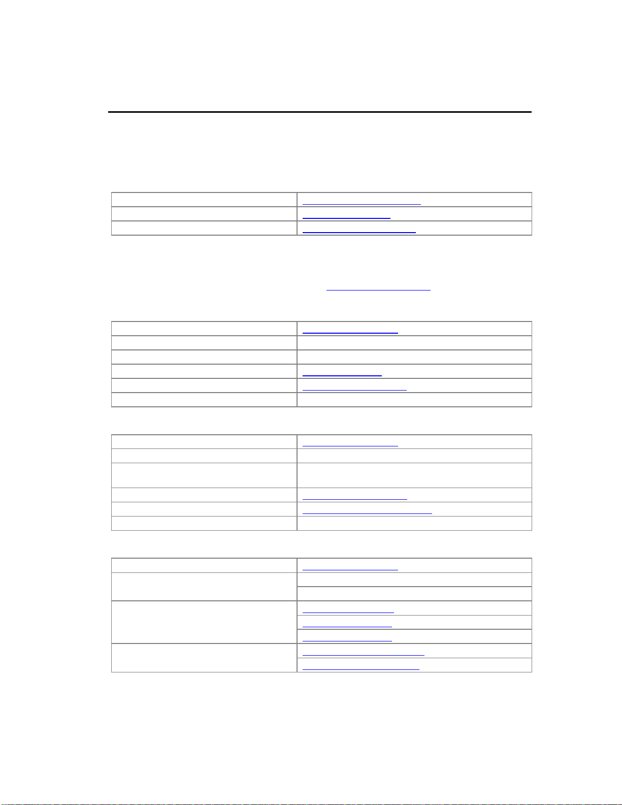
VersaMax PLC CPU
power supply
VersaMax Modules
1
CPU Modules for VersaM ax P LCs
A VersaMax PLC consists of a group of VersaMax modules with a VersaMax
CPU and attached power supply in the first position.
All VersaMax CPUs provide powerful PLC functionality. They are designed to
serve as the system controller for up to 64 modules with up to 2048 I/O points.
Two serial ports provide RS-232 and RS-485 interfaces for SNP slave and RTU
slave communications.
VersaMax CPUs are described in GFK-1503, VersaMax PLC User’s Manual.
This document also provides programming information for the VersaMax PLC.
Basic CPU Features
Programming in Ladder Diagram, Sequential Function Chart, and
Instruction List
Floating point (real) data functions
Non-volatile flash memory for program storage
Battery backup features for program, data, and time of day clock
Super capacitor provides power to memory for 1 hour
Over 1 hour, backup battery protects memory contents up to 6 months.
Backup battery has shelf life of 5 years when not in use.
Run/Stop switch
Embedded RS-232 and RS-485 communications
1-4 VersaMax Modules, Power Supplies and CarriersUser Manual GFK-1504N
Page 13
1
RS485
PORT 2
RS232
PORT 1
CPU001
PORT 2
FORCE
PORT 1
FAULT
RUN
PWR
OK
RS485
PORT 2
RS232
PORT 1
CPU005
FAULT
RUN
PWR
OK
PORT 2
FORCE
PORT 1
CPU001
CPU002
CPU005
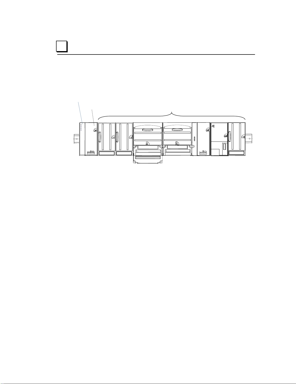
Status LEDs
Serial Ports
RS485
PORT 2
RS232
PORT 1
CPUE05
FAULT
RUN
PWR
OK
PORT 2
FORCE
PORT 1
PORT 1
LAN
STAT
ETHERNET
10 BASE T /
100 BASE TX
ETHERNET
RESTART
CPUE05
Ethernet Interface
Available VersaMax CPUs
CPU with Two Serial Ports, 34kB of Configurable Memory IC200CPU001
CPU with Two Serial Ports, 42kB of Configurable Memory IC200CPU002
CPU with Two Serial Ports, 128kB of Configurable Memory IC200CPU005
CPU with Two Serial Ports and Embedded Ethernet Interface,
128kB of Configurable Memory
IC200CPUE05
GFK-1504N Chapter 1 Introduction 1-5
Page 14
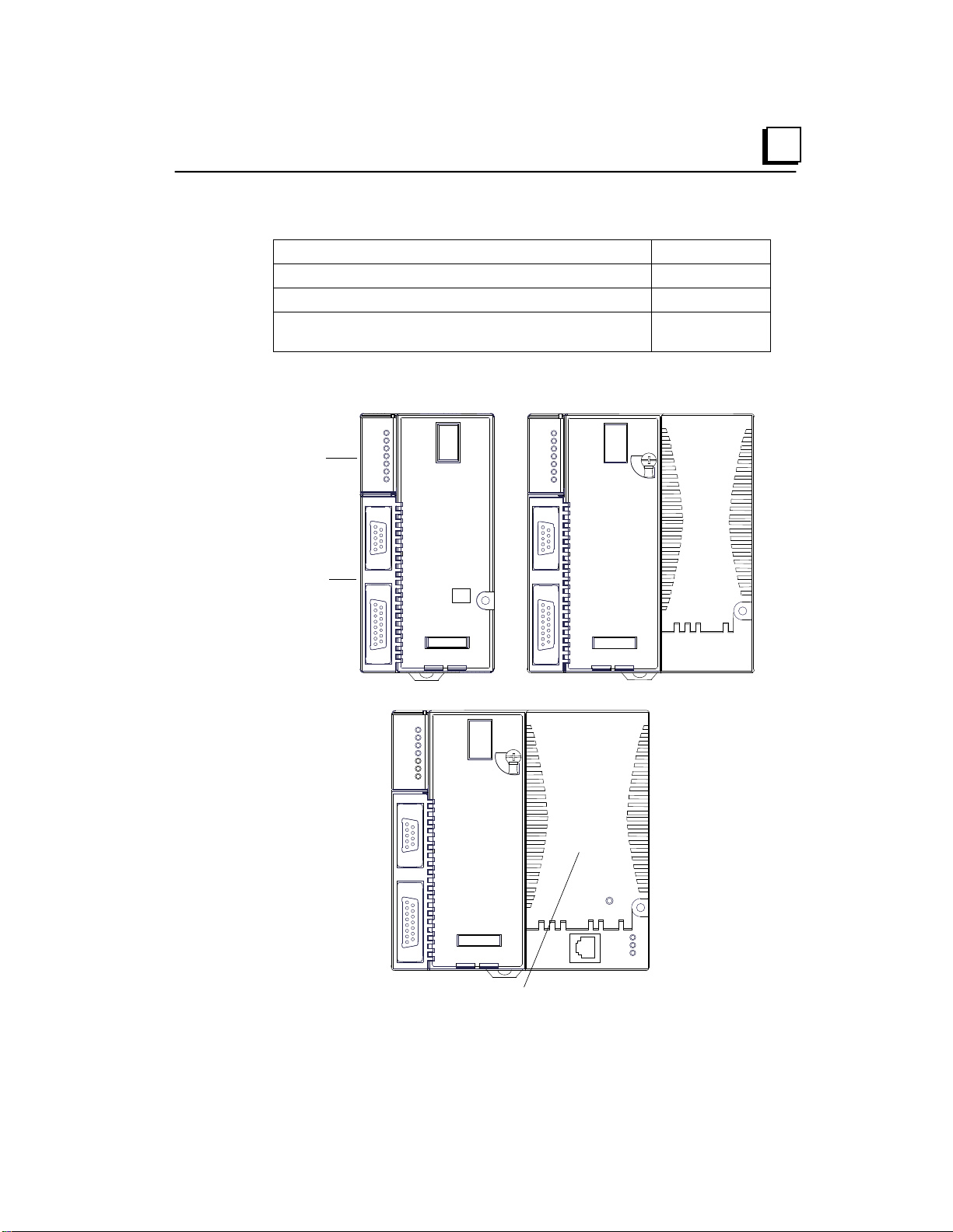
VersaMax NIU
power supply
VersaMax Modules
SHIELD OUT
SERIAL B2
SHIELD IN
SERIAL A2
SHIELD OUT
SERIAL B1
SHIELD IN
SERIAL A1
0
1
0 0 7
6
4
5
8
9
1
1
BAUD
RATE
SBA
X10
3
2
3
2
3
2
GBI001
BUS B
SBA ERR
I/O ENBL
FORCE
PWR
FAULT
OK
SBA
X1
U
N
A
N
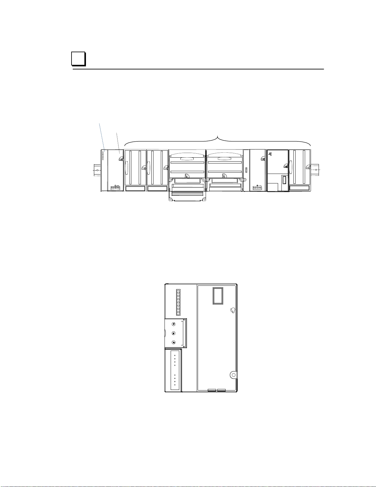
Genius® NIU
IC200GBI001
1
Network Interface Uni t s
A VersaMax I/O Station consists of a group of VersaMax modules with a
VersaMax Network Interface Unit (NIU) module and attached power supply in
the first position.
The NIU provides I/O scanning and a communications interface, allowing a
group of VersaMax modules to function as an I/O station on a communications
bus. The power supply on the NIU provides power for the modules in the I/O
Station. Additional “booster” power supplies can be included in the system if
needed for modules with high current requirements.
A NIU module has connectors appropriate for its communications network type
and status LEDs. NIUs also have rotary dials that can be used to set
communications ID information and other parameters.
Genius NIU
1-6 VersaMax Modules, Power Supplies and CarriersUser Manual GFK-1504N
Page 15
1
Available VersaMax NIUs
Ethernet NIU
The Ethernet NIU (IC200EBI001) serves as the connection point between
VersaMax I/O modules and a single 10/100Base-T Ethernet network. The NIU
supports Modbus/TCP protocol. For information about the Ethernet NIU, refer to
GFK-1860, VersaMax System Ethernet Network Communications User’s
Manual.
DeviceNet NIU
The DeviceNet NIU (IC200DBI001) is a DeviceNet slave module. DeviceNet
supports a variety of communication structures including peer to peer, multimaster and master/slave with broadcasting capabilities. Up to 64 nodes can be
connected to a DeviceNet network without bridging or routing. For information
about the DeviceNet NIU, refer to GFK-1533, VersaMax System DeviceNet
Network Communications User’s Manual.
Ethernet NIU IC200EBI001
Profibus NIU IC200PBI001
Genius NIU IC200GBI001
DeviceNet NIU IC200DBI001
Profibus NIU
The Profibus NIU (IC200PBI001) operates as a slave on a Profibus-DP
Network, automatically exchanging I/O, status, control, and diagnostic data with
a master device. The NIU is capable of handling up to 375 bytes of I/O data,
consisting of up to 244 bytes of discrete and analog input data and up to 244
bytes of discrete and analog output data. The system host can be any device
capable of operating as a bus master. For information about the Profibus-DP
NIU, refer to GFK-1534, VersaMax System Profibus Network Modules User’s
Manual (revision A or later).
Genius NIU
The Genius NIU (IC200GBI001) operates as a device on a Genius bus. The
NIU is capable of handling up to 128 bytes of discrete and analog input data and
128 bytes of discrete and analog output data. The system host can be any PLC
or computer capable of controlling the Genius bus. For information about the
Genius NIU, refer to GFK-1535, VersaMax System Genius Network Interface
Unit User’s Manual.
GFK-1504N Chapter 1 Introduction 1-7
Page 16
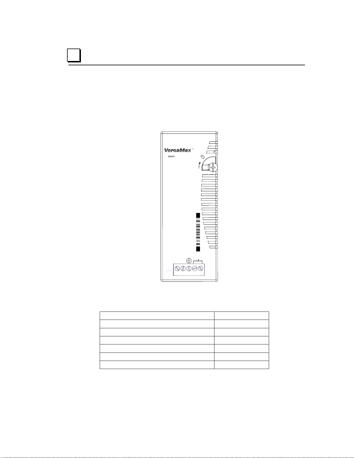
IC200PWR001
VDC
+
INPUT
-
24 VDC, 11 W
POWER SUPPLY
NOT
USED
24VDC Power Supply
IC200PWR001
24VDC Expanded 3.3V Power Supply
IC200PWR002
120/240VAC Power Supply
IC200PWR101
120/240VAC Expanded 3.3V Power Supply
IC200PWR102
12VDC Power Supply
IC200PWR201
12VDC Expanded 3.3V Power Supply
IC200PWR202
Power Supply Booster Carrier
IC200PWB001
1
Power Supplies
An AC or DC Power Supply module installs directly on the CPU or NIU. The
power supply provides +5V and +3.3V power to the modules in the station.
Additional power supplies can be installed on special booster carriers, if
needed, for systems where the number of modules creates the need for a
booster. The AC or DC power supply on the CPU or NIU and the power supply
that resides on the Booster carrier must share the same external power source.
Available Power Supplies and Carrier
1-8 VersaMax Modules, Power Supplies and CarriersUser Manual GFK-1504N
The following table lists the available VersaMax power supplies and carrier.
Power supplies are described in chapter 3 of this manual.
Page 17
1
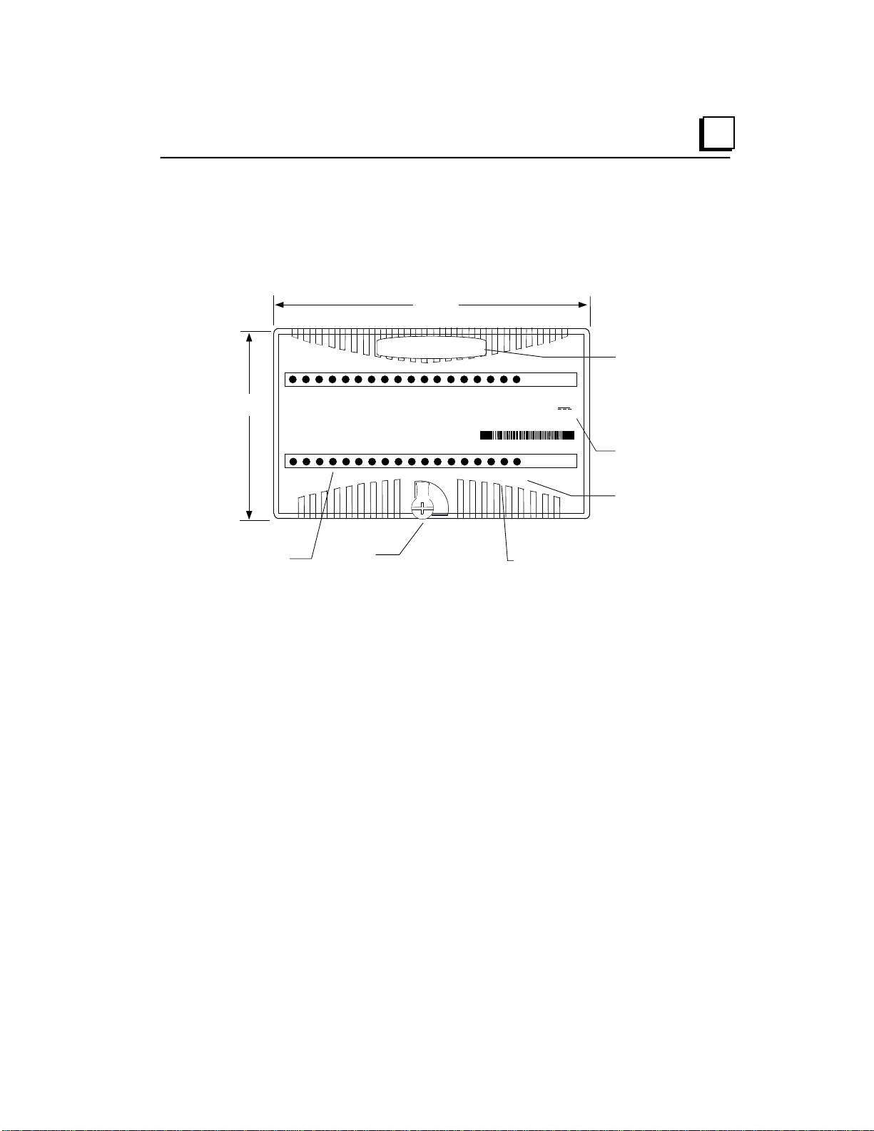
66.8mm
(2.63in)
110mm
(4.33in)
Latch
Individual Point LEDS
on Discrete Modules
Field Power LED
indicates presence of
power from external
supply
OK LED indicates
presence of power from
VersaMax power supply
Color code:
Red: AC
Blue: DC
Gold: Mixed
Gray: Analog/other
Module
Description
1234567 831
FLD
PWR
OK
IC200MDL750
OUTPUT 12/24VDC
POS GRP .5A 32PT
OK
FLD
PWR
1 2 3 4 5 6 7 8 9 10
11 12 13 14 15 16
Q
Q
17 18 19
20
21 22
23
24 25 26 27 28 29 30 31
32
I/O Modules
VersaMax IO and option modules are approximately 110 mm (4.3 in) by 66.8
mm (2.63 in) in size. Modules can be mounted either horizontally or vertically on
several types of available I/O Carriers. Modules are 50 mm (1.956 in) in depth,
not including the height of the carrier or the mating connectors.
VersaMax I/O modules discussed in this manual are grouped into chapters by
module type. For more information about a specific module, refer to the Table of
Contents or Index for the module description.
Discrete Module Point LEDs
Individual point LEDs on discrete modules provide status information at a
glance. Laser markings on the module identify the LEDs. The positions of the
point LEDs always correspond to the module’s wiring diagram, whether the
module is simple:
GFK-1504N Chapter 1 Introduction 1-9
Page 18
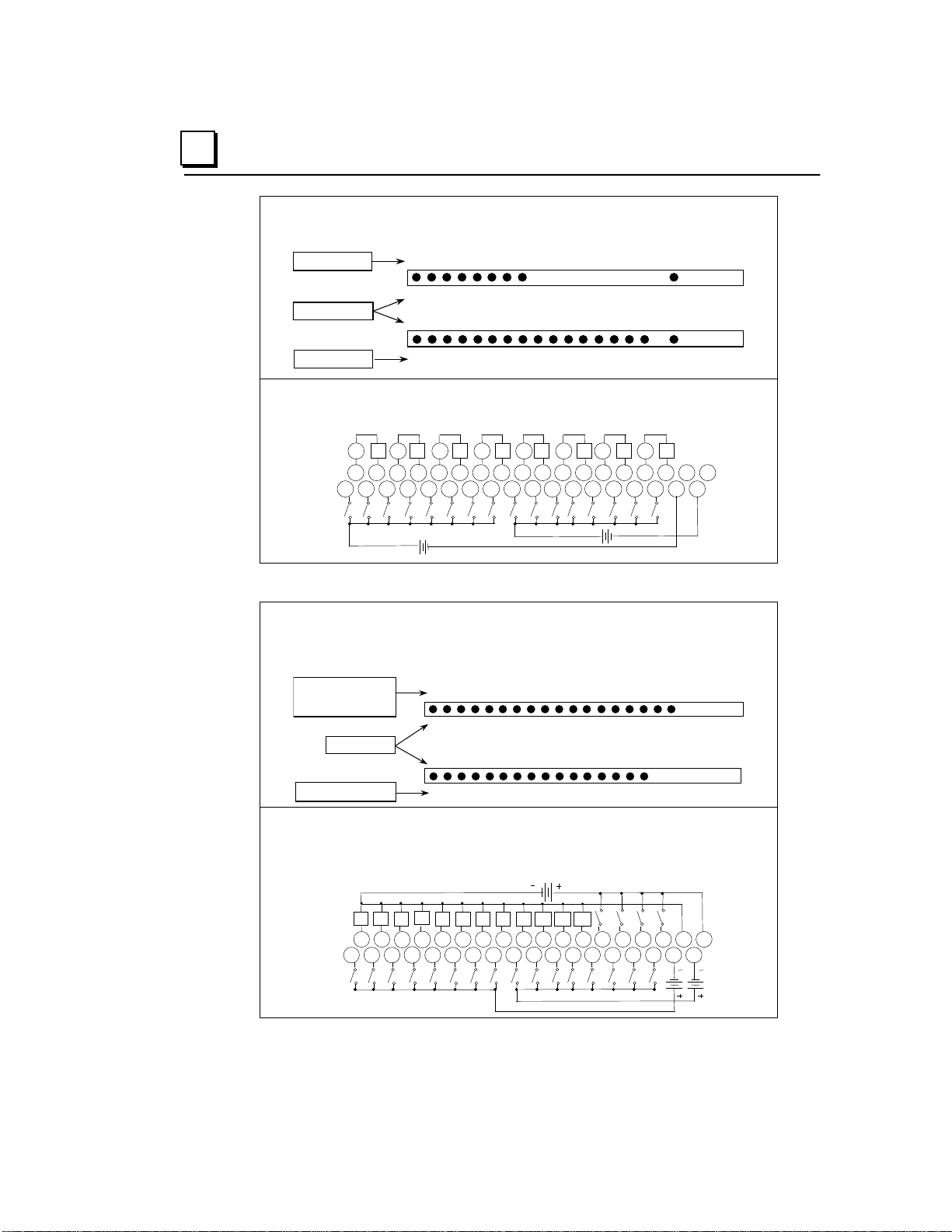
Q (output points)
Point numbers
I (input points)
1234567
8
123456789
10111213141516
OK
Q
I
OK
I1 I2 I3 I4 I5 I6 I7 I8 I9 I10 I11 I12 I13 I14 I15 I16
Q1
Q2
Q3
Q4
Q5
Q6
Q7
Q8
v v v v v v v v
1 2 3 4 5 6 7 8 9 11 12 13 14 15 16 17 18
1 2 3 4
5 6 7 8 9 11 12 13 14 15 16 17 18 10
10
B
A
+
-
(+)
(-)
+
-
(+)
(-)
-
(+) - (+)
OK
123456789101112171819
20
123456789101112131415
16
FLD
Q/I
I
Q (Output points 1 - 12)
followed by
I (input points 17 - 20)
Point numbers
I (input points 1 - 16)
1
A B
2
3
4
5
6 7
8
9
1
2
3
4
5
6 7 8
9
11
12
13
14
15
16
17
18
11
12 13
14
15
16
17
18
10
10
I1
I2
I3
I4
I5
I6
I7
I8 9 I10
I11
I12
I13
I14
I15
I16
I17
I18
I19
I20
Q1
Q2
Q3
Q4
Q5
Q6
Q7
Q8
Q9
Q10
Q11
Q12
1
LEDs for Discrete Mixed
Module IC200MDD845
Wiring Diagram for Module
IC200MDD845
or more complex:
LEDs for Discrete Mixed
High-speed Counter Module
IC200MDD841
Wiring Diagram for Mixed
High-speed Counter Module
IC200MDD841
1-10 VersaMax Modules, Power Supplies and CarriersUser Manual GFK-1504N
Page 19

1
Available I/O Modules
Discrete Input Modules
Input Module, 120VAC 8 Points IC200MDL140
Input Module, 240VAC 8 Points IC200MDL141
Input Module, 120VAC Isolated 8 Points IC200MDL143
Input Module, 240VAC Isolated 4 Points IC200MDL144
Input Module, 120VAC 16 Points IC200MDL240
Input Module, 240VAC16 Points IC200MDL241
Input Module, 120VAC Isolated 16 Points IC200MDL243
Input Module, 240VAC Isolated 8 Points IC200MDL244
Input Module, 125VDC Positive/Negative Logic Isolated 8 Points IC200MDL631
Input Module, 125VDC Positive/Negative Logic Isolated 16 Points IC200MDL632
Input Module, 48VDC Positive/Negative Logic Grouped 16 Points IC200MDL635
Input Module, 48VDC Positive/Negative Logic Grouped 32 Points IC200MDL636
Input Module, 24VDC Positive/Negative Logic 16 Points IC200MDL640
Input Module, 5/12VDC Positive/Negative Logic Grouped 16 Points IC200MDL643
Input Module, 5/12VDC Positive/Negative Logic Grouped 32 Point IC200MDL644
Input Module, 24VDC Positive/Negative Logic (32 Points IC200MDL650
Discrete Output Modules
Output Module, 120VAC 0.5 Amp, Isolated 8 Points IC200MDL329
Output Module, 120VAC 0.5 Amp, Isolated 16 Points IC200MDL330
Output Module, 120VAC 2.0 Amp, Isolated 8 Points IC200MDL331
Output Module, 24VDC Positive Logic 2.0 Amps, w/ESCP 8 Points IC200MDL730
Output Module, 12/24VDC Positive Logic 0.5 Amp, 16 Points IC200MDL740
Output Module, 24VDC Positive Logic 0.5 Amp, w/ESCP 16 Points IC200MDL741
Output Module, 24VDC Positive Logic 0.5 Amp, w/ESCP 32 Points IC200MDL742
Output Module, 5/12/24V DC Negative Logic 0.5 Amp, 16 Points IC200MDL743
Output Module, 5/12/24VDC Negative Logic 0.5 Amp, 32 Points IC200MDL744
Output Module, 12/24VDC Positive Logic 0.5 Amp, 32 Points IC200MDL750
Output Module, Relay 2.0 Ampt Isolated Form A 8 Points IC200MDL930
Output Module, Relay 2.0 Amp, Isolated Form A 16 Points IC200MDL940
GFK-1504N Chapter 1 Introduction 1-11
Page 20

Discrete Mixed I/O Modules
Mixed Module, 24VDC Positive Logic Input 20 Points / Output Relay 2.0 Amp 12 Points
IC200MDD840
Mixed Module, 24VDC Positive Logic Input 20 Points / Output 12 Point / (4) High Speed
IC200MDD841
Mixed Module, Output 24VDC Pos. Logic 0.5A Grouped w/ESCP 16 Points / Input 24VDC
Pos/Neg Logic Grouped 16 Points
IC200MDD842
Mixed Module, 24VDC Positive Logic Input Grouped 10 Points / Output Relay 2.0A per Point
Grouped 6 Points
IC200MDD843
Mixed Module, Output 12/24VDC Pos. Logic 0.5A 16 Points / Input 24 VDC Pos/Neg Logic
Grouped 16 Points
IC200MDD844
Mixed Module, Output Relay 2.0A Isolated 8 Points / Input 24VDC Pos/Neg Logic Grouped
16 Points
IC200MDD845
Mixed Module, Output Relay 2.0A per Pt Isolated 8 Points / Input 120VAC Grouped 8 Points
IC200MDD846
Mixed Module, Output Relay 2.0A per Pt Isolated 8 Points / Input 240VAC Grouped 8 Points
IC200MDD847
Mixed Module, Output 120VAC 0.5A per Pt Isolated 8 Points / Input 120VAC Grouped 8
Points
IC200MDD848
Mixed Module Output Relay 2.0A per Pt Isolated 8 Points / Input 120VAC Isolated 8 Points
IC200MDD849
Mixed Module, Output Relay 2.0A per Pt Isolated 8 Points / Input 240VAC Isolated 4 Points
IC200MDD850
Mixed Module, Output 12/24VDC Pos. Grouped 16 Pts / Input 5/12VDC Pos/Neg Grp16 Pts
IC200MDD851
Analog Input Modules
Analog Input Module,12 Bit Voltage/Current 4 Channels
IC200ALG230
Analog Input Module, 16 Bit Voltage/Current, 1500VAC Isolation, 8 Channels
IC200ALG240
Analog Input Module, 12 Bit Voltage/Current 8 Channels
IC200ALG260
Analog Input Module, 15 Bit Voltage Differential 8 Channels
IC200ALG261
Analog Input Module, 15 Bit Current Differential 8 Channels
IC200ALG262
Analog Input Module, 15 Bit Voltage 15 Channels
IC200ALG263
Analog Input Module, 15 Bit Current 15 Channels
IC200ALG264
Analog Input Module, 15 Bit Voltage 15 Channels, SIL2 Rated, Enhanced Diagnostics
IC200ALG265
Analog Input Module, 15 Bit Current 15 Channels, SIL2 Rated, Enhanced Diagnostics
IC200ALG266
Analog Input Module, 16 Bit RTD, 4 Channels
IC200ALG620
Analog Input Module, 16 Bit Thermocouple, 7 Channels
IC200ALG630
Analog Output Modules
Analog Output Module, 12 Bit Current, 4 Channels
IC200ALG320
Analog Output Module, 12 Bit Voltage 0 to 10VDC 4 Channels
IC200ALG321
Analog Output Module, 12 Bit Voltage -10 to +10VDC 4 Channels
IC200ALG322
Analog Output Module, 13 Bit Voltage 8 Channels
IC200ALG325
Analog Output Module, 13 Bit Current 8 Channels
IC200ALG326
Analog Output Module, 13 Bit Voltage 12 Channels
IC200ALG327
Analog Output Module, 13 Bit Current 12 Channels
IC200ALG328
Analog Output Module, 16 Bit Voltage/Current, 1500VAC Isolation, 4 Channels
IC200ALG331
Analog Mixed I/ O Modules
Analog Mixed Module, 12 Bit Input Current 4 Channels and Output Current 2 Channels
IC200ALG430
Analog Mixed Module, 12 Bit 0 to 10VDC Input 4 Channels and Output 2 Channels
IC200ALG431
Analog Mixed Module, 12 Bit +/-10VDC Input 4 Channels and Output 2 Channels
IC200ALG432
1
Counter, PWM, or Pulse Train Configurable Points
1-12 VersaMax Modules, Power Supplies and CarriersUser Manual GFK-1504N
Page 21
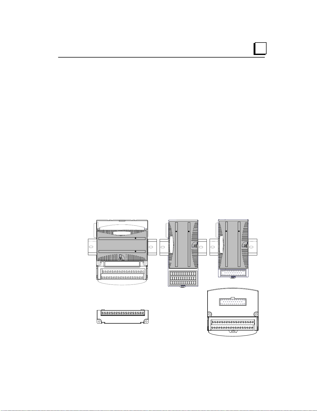
1
Terminal-style I/O
Carrier
Compact Terminal-
style I/O Carrier
Connector-style I/O
Carrier and
Interposing Terminals
Auxiliary I/O
Terminal Strip
Carriers
Carriers provide mounting, backplane communications, and field wiring
connections for all types of VersaMax modules. I/O modules can be installed
on carriers or removed without disturbing field wiring.
There are three basic I/O Carrier types:
Terminal-style I/O carriers. Modules mount parallel to the DIN rail.
Compact Terminal-style I/O Carriers. Modules mount perpendicular to the
DIN rail.
Connector-style I/O Carriers. Modules mount perpendicular to the DIN rail.
These carriers are normally used with Interposing I/O Terminals. One type
of Interposing I/O Terminals is illustrated below; other types are also
available.
Refer to chapter 4 for information about VersaMax I/O Carriers.
Terminal-style I/O carriers have 36 individual terminals for direct connection of
field wiring. Auxiliary I/O Terminal Strips are available for applications requiring
additional wiring terminals. Chapter 5 describes the VersaMax Interposing
Terminals and Auxiliary I/O Terminal Strips.
GFK-1504N Chapter 1 Introduction 1-13
Page 22

Terminal-Style I/O Carriers
Barrier-Style Terminal I/O Carrier
IC200CHS001
Box-Style Terminal I/O Carrier
IC200CHS002
Spring-Style Terminal I/O Carrier
IC200CHS005
Compact Terminal-Style I/O Carriers
Compact Box-Style I/O Carrier
IC200CHS022
Compact Spring-Style I/O Carrier
IC200CHS025
Connector-Style I/O Carrier
Connector-Style I/O Carrier
IC200CHS003
Interposing Terminals for use wit h Connector-Style Carrier
Barrier-Style Interposing I/O Terminals
IC200CHS011
Box-Style Interposing I/O Terminals
IC200CHS012
Thermocouple-Style Interposing I/O Terminals
IC200CHS014
Spring-Style Interposing I/O Terminals
IC200CHS015
Disconnect-Style Interposing I/O Terminals, Main Base
Disconnect-Style Interposing I/O Terminals, Expansion Base
IC200CHS101
IC200CHS102
Relay-Style Interposing I/O Terminals, Main Base
Relay-Style Interposing I/O Terminals, Expansion Base
IC200CHS111
IC200CHS112
Fuse-Style Interposing I/O Terminals, Expansion Base
IC200CHS122
Cables for use with Connector-Style I/O Carriers
2 connectors, 0.5m, no shield
IC200CBL105
2 connectors, 1.0m, no shield
IC200CBL110
2 connectors, 2.0m, no shield
IC200CBL120
1 connector, 3.0m, no shield
IC200CBL230
Auxiliary I/O Terminal Strips for use with Terminal-style I/O Carriers and Interposing Terminals
Barrier-Style Auxiliary I/O Terminal Strip
IC200TBM001
Box-Style Auxiliary I/O Terminal Strip
IC200TBM002
Spring-Style Auxiliary I/O Terminal Strip
IC200TBM005
Other Carriers
Communications Carrier
IC200CHS006
Power Supply Booster Carrier
IC200PWB001
1
Available I/O Carriers and Terminal Strips
Fuse-Style Interposing I/O Terminals, Main Base
IC200CHS121
1-14 VersaMax Modules, Power Supplies and CarriersUser Manual GFK-1504N
Page 23
1
PS
CPU/NIU
PS
ERM
PS
ERM
ETM
VersaMax ExpansionRack 1
Terminator
Plug
15M with any
IC200ERM002 ERMs
750M with all
IC200ERM001 ERMs
VersaMax PLC or I/O Station Main Rack (0)
VersaMax ExpansionRack 7
IC200CBL601,
602, 615
PS
ERM
VersaMax Expansion Rack
1 M
VersaMax PLC or NIU I/O Station Main Rack
PS
CPU/NIU
IC200CBL601
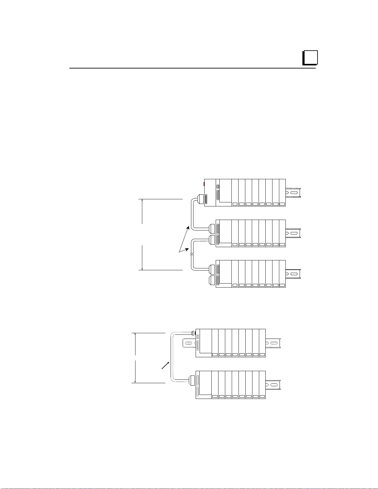
Expansion Modules
There are two basic types of VersaMax I/O expansion systems, Multi-Rack and
Two-Rack Local:
Multi-Rack: A VersaMax PLC or NIU I/O Station with an Expansion
Transmitter Module (IC200ETM001) and one to seven expansion “racks”,
each with an Expansion Receiver Module (IC200ERM001 or
IC200ERM002). If all the Expansion Receivers are the Isolated type
(IC200ERM001), the maximum overall cable length is 750 meters. If the
expansion bus includes any non-isolated Expansion Receivers
(IC200ERM002), the maximum overall cable length is 15 meters.
Two-Rack Local: A CPU or NIU I/O Station connected directly to one
expansion rack with non-isolated Expansion Receiver Module
(IC200ERM002). Maximum cable length is 1 meter.
GFK-1504N Chapter 1 Introduction 1-15
Page 24
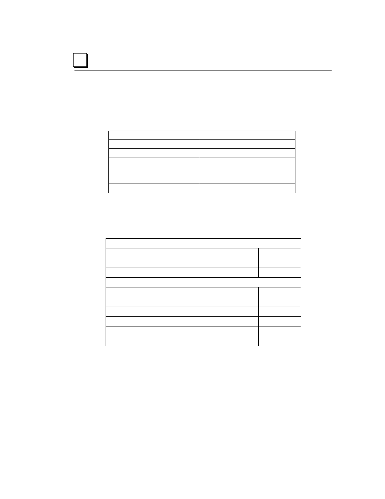
Module
Module Revision
IC200ALG320
B or later
IC200ALG321
B or later
IC200ALG322
B or later
IC200ALG430
C or later
IC200ALG431
C or later
IC200ALG432
B or later
1
VersaMax Modules for Expansion Racks
All types of VersaMax I/O and communications modules can be used in
expansion racks. Some VersaMax analog modules require specific module
revisions, as listed in the following table.
Available Expansion Module s
Expansion Modules
Expansion Transmitter Module IC200ETM001
Expansion Receiver Module, Isolated IC200ERM001
Expansion Receiver Module, Non-isolated IC200ERM002
Cables
Expansion Cable, Shielded, 1 meter IC200CBL601
Expansion Cable, Shielded, 2 meters IC200CBL602
Expansion Cable, Shielded, 15 meters IC200CBL615
Firmware Update Cable IC200CBL002
Terminator Plug (included with ETM) IC200ACC201
Connector Kit IC200ACC302
Refer to chapter 6 for information about VersaMax Expansion modules.
1-16 VersaMax Modules, Power Supplies and CarriersUser Manual GFK-1504N
Page 25
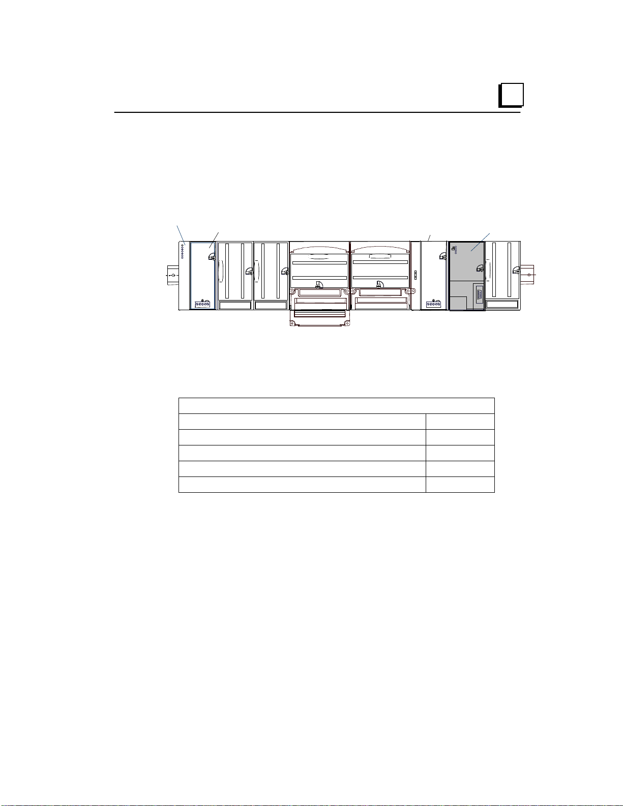
1
VersaMax PLC CPU
power supply
Optional booster
power supply
Profibus Network
Slave Module
Communications Modules
Communications modules provide additional flexibility for VersaMax systems.
These communications modules install on a VersaMax Communications Carrier.
Power for the communications module comes from the main system power supply
or from a booster supply as displayed in the following figure.
Available VersaMax PLC Communications Modules
Communications Modules
Profibus-DP Network Slave Module IC200BEM002
DeviceNet Network Control Module IC200BEM103
Asi Network Master Module IC200BEM104
Communications Carrier IC200CHS006
Serial Communications Module IC200CMM020
For information about the Communications Carrier, refer to chapter 4.
Profibus-DP Network Slave Module
The Profibus-DP Network Slave Module (IC200BEM002) is a communications
module that exchanges PLC reference table data on the Profibus network. The
VersaMax PLC CPU can read and write this data as though it were conventional
bit- and word-type I/O data.
Multiple Profibus-DP Network Slave Modules may be used in the same
VersaMax PLC. Each one can read up to 244 bytes of data from the network,
and send up to 244 bytes of output data. The total amount of combined inputs
and outputs is 384 bytes.
GFK-1504N Chapter 1 Introduction 1-17
Page 26

1
For information about the Profibus-DP Network Slave Module, refer to GFK1534, VersaMax System Profibus Network Modules User’s Manual (revision A
or later).
DeviceNet Network Control Module
The DeviceNet Network Control Module (IC200BEM103) is a communications
module that can be configured to operate as a master, as a slave, or as both
simultaneously. It can exchange up to 512 bytes of input data and 512 bytes of
output data with other devices on the DeviceNet network. The VersaMax PLC
CPU can read and write this data as though it were conventional bit- and wordtype I/O data.
The Network Control Module operates as a Group 2 Only Client (master) and
can communicate only with Group 2 Slave devices. It can also operate as a
Group 2 Only or a UCMM-capable Server (slave), or as a master and slave
simultaneously.
For information about the DeviceNet Network Control Module, refer to GFK1533, VersaMax System DeviceNet Network Communications User’s Manual.
Asi Network Master Module
The VersaMax AS-Interface Network Master (IC200BEM104) conforms to the
AS-Interface Specification for the master AS-Interface protocol. It can be used
to connect a VersaMax PLC or I/O station NIU to an Actuator-Sensor network.
The AS-Interface module supports communications with up to 31 slave devices,
exchanging to exchange up to 4 bits of input data and 4 bits of output data per
slave address on the Actuator-Sensor network.
For information about the AS-Interface Network Master Module, refer to GFK1697, VersaMax System ASI Network Communications User’s Manual.
Serial Communications Module
The VersaMax Serial Communications Module, IC200CMM020, operates as a
Modbus RTU Master in a VersaMax I/O Station. The Serial Communications
module receives commands from a remote host such as an RX7i PLC.
1-18 VersaMax Modules, Power Supplies and CarriersUser Manual GFK-1504N
Page 27

1
Environmental
Vibration
IEC68-2-6
1G at 57-150Hz, 0.012in p--p at 10-57Hz
Shock
IEC68-2-27
15G, 11ms
0 to +60 deg C ambient
auxiliary I/O terminals
Storage Temperature
-40 to +85 deg C
Humidity
5% to 95%, noncondensing
protection from dust & splashing water
EMC Emission
(Group 1, Class A)
CISPR 22/EN 55022
Information Technology Equipment (Class A)
Radio Devices (Class A)
EMC Immunity
Electrostatic Discharge
EN 61000-4-2
8KV Air, 4KV Contact
rms
100%AM with 200Hz square wave
Fast Transient Burst
EN 61000-4-4
2KV: power supplies, 1KV: I/O, communication
power supplies, I/O [12V-240V]
power supplies, I/O [12V-240V]
modules)
rms
Isolation
Dielectric Withstand
UL508, UL840, IEC664
1.5KV for modules rated from 51V to 250V
Power Supply
Variation for DC ±20%
VersaMax General Product S pecifications
VersaMax products should be installed and used in conformance with productspecific guidelines, as well as the specifications listed in the following table.
Operating Temperature
Enclosure Protection IEC529 Steel cabinet per IP54:
Radiated, Conducted CISPR 11/EN 55011 Industrial Scientific & Medical Equipment
FCC 47 CFR 15 Referred to as FCC part 15,
RF Susceptibility EN 61000-4-3 10V
ENV 50140/ENV 50204 10V
Surge Withstand ANSI/IEEE C37.90a Damped Oscillatory Wave: 2.5KV:
IEC255-4 Damped Oscillatory Wave: Class II,
-40 to +60 deg C ambient for I/O carriers,
communications carrier, interposing I/O terminals, and
/m, 80 to 1000Mhz, 80% AM
/m, 900MHz ±5MHZ
rms
EN 61000-4-5 2 kV cm(P/S); 1 kV cm (I/O and communication
Conducted RF EN 61000-4-6 10V
Input Dips, Variations EN 61000-4-11 During Operation: Dips to 30% and 100%,
GFK-1504N Chapter 1 Introduction 1-19
, 0.15 to 80Mhz, 80%AM
Variation for AC ±10%,
Page 28

Chapter
2
Installation
This section provides the following installation instructions:
Pre-installation Check
Conformance to Standards
Thermal Clearance
DIN Rail and Panel Mounting
Installing Carriers
Expansion System Installation
Installing a Power Supply
System Wiring Guidelines
System Grounding
Installing Wiring for I/O Devices
Installing Modules
GFK-1504N 2-1
Page 29

2
Pre-installation Check
Carefully inspect all shipping containers for damage during shipping. If any part
of the system is damaged, notify the delivery service immediately. The
damaged shipping container should be saved as evidence for inspection by the
delivery service. It is the user’s responsibility to register a claim with the delivery
service for damage incurred during shipment.
After unpacking the VersaMax modules and other equipment, record all serial
numbers. Serial numbers are required if you should need to contact Product
Service during the warranty period of the equipment. All shipping containers and
all packing material should be saved should it be necessary to transport or ship
any part of the system.
Conformance to Standards
Before installing VersaMax products in situations where compliance to
standards or directives from the Federal Communications Commission, the
Canadian Department of Communications, or the European Union is required
please refer to GFK-1179, Installation Requirements for Conformance to
Standards.
▪ Power Supply Modules: Be sure to read the installation instructions
provided with each Power Supply module. These instructions specify the
use of copper conductors for the power supply, wire gauge and type.
▪ Control circuit modules: Be sure to read the installation instructions provided
with the module. These instructions specify the use of copper conductors
and wire gauge and type requirements.
▪ Equipment labeled with reference to Class I, Div. 2, Groups A, B, C and D,
Hazardous Locations is suitable for use in Class I, Div. 2, Groups A, B, C, D
or non-hazardous locations only.
▪ Equipment labeled with reference to Class I, Zone 2, Groups A, B, C and D,
hazardous locations is suitable for use in Class I, Zone 2, Groups A, B, C, D
or non-hazardous locations only.
▪ Battery in CPU Category No. IC200CPU001 and IC200CPU002 is to be
replaced only with Matsushita No. BR2032. The correct battery type is
available as Accessory Kit IC200ACC001.
2-2 VersaMax Modules, Pow er S uppl i es and CarriersUser Manual GFK-1504N
Page 30

2
Installation in Hazardous Locations
▪ WARNING - EXPLOSION HAZARD - SUBSTITUTION OF COMPONENTS
MAY IMPAIR SUITABILITY FOR CLASS I, DIVISION 2;
▪ WARNING - EXPLOSION HAZARD - WHEN IN HAZARDOUS
LOCATIONS, TURN OFF POWER BEFORE REPLACING OR WIRING
MODULES; AND
▪ WARNING - EXPLOSION HAZARD - DO NOT CONNECT OR
DISCONNECT EQUIPMENT UNLESS POWER HAS BEEN SWITCHED
OFF OR THE AREA IS KNOWN TO BE NONHAZARDOUS.
GFK-1504N Chapter 2 Installation 2-3
Page 31

5.1cm
(2.0in)
2.54cm
(1.0in)
5.1cm
(2.0in)
2.54cm
(1.0in)
5.1cm
(2.0in)
2.54cm
(1.0in)
5.1cm
(2.0in)
2.54cm
(1.0in)
CPU or NIU
at Bottom
2
Thermal Considerations
The thermal performance specified for modules in this manual requires a
clearance of 5.1 cm (2 in) above and below the modules and 2.54 cm (1 in) on
each side of the modules as shown below, regardless of the orientation of the
DIN rail.
When using a vertical DIN rail, the CPU or NIU module must be installed at the
bottom.
Individual modules have may additional clearance requirements. Refer to
Appendix A.
2-4 VersaMax Modules, Pow er S uppl i es and CarriersUser Manual GFK-1504N
Page 32

2
Hole for Optional
Panel-Mounting
DIN Rail and Panel Mounting
Each rack in a VersaMax PLC or VersaMax I/O Station must be installed on a
single section of 7.5 mm x 35 mm DIN rail, 1 mm thick. Steel DIN rail is
recommended. “Rack” is the term used for a CPU, NIU, or Expansion Receiver,
plus up to 8 physically-connected I/O carriers. The first rack in a system is
called Rack 0. If there are multiple expansion racks, Rack 0 also includes an
Expansion Transmitter module installed in the leftmost position, before the CPU
or NIU.
The DIN rail used in a VersaMax installation must be electrically grounded to
provide EMC protection. The rail must have a conductive (unpainted) corrosionresistant finish. DIN rails compliant with DIN EN50022 are preferred.
For vibration resistance, the DIN rail should be installed on a panel using
screws spaced approximately 5.24 cm (6 in) apart. DIN-rail clamps (part
number IC200ACC313) can also be installed at both ends of the station to lock
the modules in position.
For applications requiring maximum resistance to mechanical vibration and
shock, the DIN-rail-mounted carriers should also be mounted on the panel.
Panel mount holes can be located on the panel by using the carrier as a
template, or by following the dimensions provided in Appendix A. Pre-drill the
mounting holes and install the CPU, NIU, ERM, and carriers using M3.5 (#6)
screws.
GFK-1504N Chapter 2 Installation 2-5
Page 33

Connector Cover
Connector Cover
2
DIN Rail Installation Steps
VersaMax CPUs, Network Interface Unit (NIU) modules, Expansion Receiver
(ERM) modules, and module carriers snap easily onto the DIN rail. No tools are
required for mounting or grounding to the DIN rail.
Before joining module carriers to a CPU, NIU, or ERM, remove the connector
cover on the right-hand side of the CPU, NIU, or ERM. Do not discard this
cover. You will need to install it on the last carrier.
Slide carriers along the DIN rail to engage the connectors in the sides of
adjacent carriers. To avoid damaging connector pins, do not force or slam
carriers together.
Install the connector cover that was removed over the connector on the last
carrier to protect the connector pins and to provide compliance with standards.
2-6 VersaMax Modules, Pow er S uppl i es and CarriersUser Manual GFK-1504N
Page 34

2
PWR
EXP TX
On indic ates presence of 5VDC power.
Off indicates no 5VDC power.
Blinking or On indicates active
communicati ons on expansion bus.
Off indicates no communications.
Installing an Expansion Transmitter Module
An Expansion Transmitter Module must be installed to the left of a CPU or NIU.
1. Make sure rack power is off.
2. Attach the Expansion Transmitter to DIN rail to the left of the CPU or NIU.
3. Slide the module toward the CPU or NIU and press together until the
connectors are mated.
4. After completing any additional system installation steps, apply power and
observe the module LEDs.
Removing an Expansion Transmitter Module
1. Make sure rack power is off.
2. Slide module on DIN rail away from the CPU or NIU in the main rack.
3. Using a small screwdriver, pull down on the tab on the bottom of the
module and lift the module off the DIN rail.
GFK-1504N Chapter 2 Installation 2-7
Page 35

5
7
6
4
1
3
2
0
PWR
EXP RX
SCAN
On indicates presence of 5VDC power.
Off i ndic ates no 5VDC power.
Blinking or On indicates module is
communicating on expansion bus
Off i ndic ates module not communicating
Green indi cates CPU/NIU is scanning I /O
in expansion racks.
Amber indicates not sc anning.
2
Installing an Expansion Rec eiver Module
An Expansion Receiver Module (IC200ERM001 or 002) must be installed in the
leftmost slot of each VersaMax expansion rack.
1. Insert the label inside the small access door at the upper left corner of the
module.
2. Attach the module to the DIN rail at the left end of the expansion rack.
3. Select the expansion rack ID (1 to 7) using the rotary switch under the
access door at upper left corner of the module. Each rack must be set to a
different rack ID. With a single-ended cable (one expansion rack only), set
the Rack ID to 1.
4. Install a VersaMax Power Supply module on top of the Expansion Receiver.
Refer to the section, Installing a Power Supply.
5. Attach the cables. If the system includes an Expansion Transmitter Module,
attach the terminator plug to the EXP2 port on the last Expansion Receiver
Module.
6. After completing system installation, apply power and observe the module
LEDs.
2-8 VersaMax Modules, Pow er S uppl i es and CarriersUser Manual GFK-1504N
Page 36

2
Removing an Expansion Receiver Module
1. Make sure rack power is off.
2. Un-install the Power Supply module from the Expansion Receiver Module.
3. Slide the Expansion Receiver Module on DIN rail away from the other
modules.
4. Using a small screwdriver, pull down on the tab on the bottom of the module
and lift the module off the DIN rail.
GFK-1504N Chapter 2 Installation 2-9
Page 37

PS
CPU/NIU
PS
ERM
PS
ERM
ETM
VersaMax ExpansionRack 1
Terminator
Plug
15M with any
IC200ERM002 ERMs
750M with all
IC200ERM001 ERMs
VersaMax PLC or I/O Station Main Rack (0)
VersaMax ExpansionRack 7
IC200CBL601,
602, 615
Expansion
Transmitter or
Expansion
Receiver
Module
Transmitting
Port
PIN
2 3
5
6
8
9
12
13
16 17
20 21
24 25
7 23
1
FR AME + FR AME-
RIRQ/+
RIRQ/-
RUN+
RUN-
RERR+
RERR-
IODT + IODT -
RSEL+
RSEL-
IOCL K+ IOCL K-
0V
0V
SHIELD
PIN
2 3
5
6
8
9
12 13
16 17
20
21
24 25
7 23
1
FR AME + FR AME-
RIRQ/+
RIRQ/-
RUN+
RUN-
RERR+ RERR-
IODT +
IODT -
RSEL+
RSEL-
IOCL K+ IOCL K-
0V
0V
SHIELD
26-PIN
FEM AL E
26-PIN
MALE
26-PIN
MALE
26-PIN
FEM AL E
VARIABLE (SEE
TEXT)
Expansion
Receiver
Module
Receiving
Port
2
Connecting the Expansion Cable: RS-485 Differential
For a multiple-rack expansion system, connect the cable from the expansion
port on the Expansion Transmitter to the Expansion Receivers as displayed in
the following figure. If all the Expansion Receivers are the Isolated type
(IC200ERM001), the maximum overall cable length is 750 meters. If the
expansion bus includes any non-isolated Expansion Receivers (IC200ERM002),
the maximum overall cable length is 15 meters.
Install the Terminator Plug (supplied with the Expansion Transmitter module)
into the lower port on the last Expansion Receiver. Spare Terminator Plugs can
be purchased separately as part number IC200ACC201 (Qty 2).
RS-485 Differential Inter-Rack Connection (IC200CBL601, 602, 615)
Building a Custom Expansion Cable
Custom expansion cables can be built using Connector Kit IC200ACC202,
2-10 VersaMax Modules, Pow er Supplies and CarriersUser Manual GFK-1504N
Crimper AMP 90800-1, and Belden 8138, Manhattan/CDT M2483, Alpha
3498C, or equivalent AWG #28 (0.089mm
2
) cable.
Page 38

2
PS
ERM
VersaMax Expansion Rack
1 M
VersaMax PLC or NIU I/O Station M ain Rack
PS
CPU/NIU
IC200CBL600
Connecting the Expansion Cable: Single-ended
For a two-rack local system with one non-isolated expansion rack
(IC200ERM002) and NO Expansion Transmitter, connect the expansion cable
from the serial port on the VersaMax CPU or NIU to the Expansion Receiver as
displayed in the following figure. The maximum cable length is one meter.
Cables cannot be fabricated for this type of installation; cable IC200CBL600
must be ordered separately.
No Terminator Plug is needed in a single-ended installation; however, it will not
impede system operation if installed.
Single-Ended Inter-Rack Connection Cable (IC200CBL600)
GFK-1504N Chapter 2 Installation 2-11
Page 39

2
Installing a Power Supply
I/O and option modules receive power for their operation from the CPU, NIU, or
Expansion Receiver Module through the mating connector on the carrier. The
number of modules that can be supported depends on the power requirements
of the modules (listed in the individual module specifications).
Power Supply Booster Carriers can be used as needed to meet the power
needs of all modules. The AC or DC Power Supply on the CPU or NIU and the
Power Supply that resides on the Booster Carrier must share the same external
power source.
In some cases, the field devices served by an I/O module require additional AC
or DC power, which must be provided using an “external” power supply.
Specifications and connection details for such external power supplies are given
in the module specifications in this manual.
Installing a Power Supply Module
The power supply module installs directly on top of a CPU, NIU, ERM, or
booster carrier. The latch on the power supply must be in the unlocked position.
Align the connectors, tab, and latch post on the power supply to be parallel with
the CPU, NIU, ERM, or carrier. Press the power supply module down firmly,
until the two tabs on the bottom of the power supply click into place. Be sure the
tabs are fully inserted in the holes in bottom edge of the CPU, NIU, ERM, or
booster carrier.
Turn the latch to the locked position to secure the power supply in place.
Note: The VersaMax power supply is not hot-swappable. Hot inserting or
extracting the power supply is an improper method to power-down or power-up.
Hot inserting the power supply can cause a “Corrupted User Memory Fault”
condition. Power-cycling should only be accomplished by switching the main
power going into the power-supply.
2-12 VersaMax Modules, Pow er Supplies and CarriersUser Manual GFK-1504N
Page 40

2
Removing a Power Supply
1. Switch off the external power source to the power supply module.
2
. Turn the latch to the unlocked position.
3
. Press in the tabs on the lower edge of the power supply
4
. Pul l the power supply straight off.
GFK-1504N Chapter 2 Installation 2-13
Page 41

2
System Wiring Guidelines
Four types of wiring may be encountered in a typical factory installation:
Power wiring – the plant power distribution, and high power loads such as
high horsepower motors. These circuits may be rated from tens to
thousands of KVA at 220 V AC or higher.
Control wiring – usually either low voltage DC or 120 V AC of limited energy
rating. Examples are wiring to start/stop switches, contactor coils, and
machine limit switches. This is generally the interface level of discrete I/O.
Analog wiring – transducer outputs and analog control voltages. This is the
interface level to I/O analog blocks.
Communications and signal wiring – the communications network that ties
everything together, including computer LANs, MAP, and field busses.
These four types of wiring should be separated as much as possible to reduce
the hazards from insulation failure, incorrect wiring, and interaction (noise)
between signals. A typical control system may require some mixing of the latter
three types of wiring, particularly in cramped areas inside motor control centers
and on control panels.
In general, it is acceptable to mix the communications bus cable with the I/O
wiring from the blocks, as well as associated control level wiring. All noise
pickup is cumulative, depending on both the spacing between wires, and the
distance span they run together. I/O wires and communications bus cable can
be placed randomly in a wiring trough for lengths of up to 50 ft. If wiring is cord–
tied (harnessed), do not include the bus cable in the harness, since binding
wires tightly together increases the coupling and mechanical stress that can
damage the relatively soft insulation of some serial cable types. Consider using
shielded cable in electrically noisy environments.
External wiring to the equipment and in cable trays should be separated
following National Electrical Code practices.
1
2-14 VersaMax Modules, Pow er Supplies and CarriersUser Manual GFK-1504N
Page 42

2
DC+
DC-
H
N
Installing Power and Ground Wiring
Power Supply terminals accommodate one AWG #14 (avg. 2.1mm2 cross
section) to AWG #22 (avg. 0.36mm
AWG #18 (avg. 0.86mm
2
cross section). Use copper wire rated for 90 deg C.
2
cross section) wire, or two wires up to
When inserting two wires in the same position, the wires must be the same size
and the same type (solid or stranded).
Connect the ground terminal to the conductive mounting panel with a 4 in
maximum length of AWG #14 (avg. 2.1mm
2
) wire. Use hardware such as star
washers to ensure ground integrity.
Grounding DC Power Supplies
DC power supplies are non-isolated. DC- must be grounded to frame / earth
ground. DC- is grounded to frame internally in the Power Supply. As a result,
floating power supplies cannot be used.
Grounding AC Power Supplies
AC power supplies are isolated. Therefore, the AC source does not have to be
grounded. However, it is recommended to only use ground-referenced sources
such as a neutral line or grounded center-tap transformer.
GFK-1504N Chapter 2 Installation 2-15
Page 43

JUMPER
FOR 120V
2
Jumper Installation on an AC Power Supply Module
AC power supply modules (IC200PRW101 and IC200PWR102) can be used
with either 120 V AC or 240 V AC nominal input power. For 120 V AC nominal
operation, install a jumper as marked on the power supply. Use insulated AWG
#14 (avg. 2.1mm
wire.
The power supply operates without a jumper installed; however, the hold-up
specification is not met. If a jumper is not installed for 120 V AC operation, the
power supply will not cause hazardous conditions.
Warnings
DO NOT USE A JUMPER FOR 240V AC OPERATION. If a jumper is used on
the input connector for 240V AC nominal operation, the power s u p p ly will
be damaged and may cause hazardous conditions.
Do not touch the exposed portions of the jumper wire with power applied
to the system. Hazardous voltages are present that could cause personal
injury.
2
cross section) to AWG #22 (avg. 0.36mm2 cross section)
2-16 VersaMax Modules, Pow er Supplies and CarriersUser Manual GFK-1504N
Page 44

2
+
-
DC: +
or
AC: H
DC: -
or
AC: N
Installing Additional Suppression
For agency compliance, external Metal Oxide Varistor (MOV) suppression is
required from both the positive and negative input to frame ground or at the
power line input of a system enclosure. The MOV should be sized to handle
line transients. Examples of suitable MOVs to handle normal line transients
include the following products manufactured by Littelfuse:
V36ZA80 (Non-isolated 24 V DC
V130LA20AP (120 V AC applications)
V275LA40BP (240 V AC applications)
Measurement of actual transients may be required in extreme cases to decide
what MOV is best.
Installing Suppression at the Pow er Supply
The following figure displays typical power and ground connections.
GFK-1504N Chapter 2 Installation 2-17
Page 45

Enclosure
Power
to
Modules
Short Length of
Communications
Bus Cable
2
Installing Suppression for Devi ces in an Enclosure
For a group of devices installed in an enclosure, MOVs can be installed at the
point where the power lines enter the enclosure. Ideally, MOVs should be used
at each cabinet in the system for maximum protection. The following figure
illustrates suppression on both power lines and a communications bus entering
an enclosure.
Periodic Inspection and Replacement of MOVs
MOVs do a good job of absorbing transients on communications, control, and
power lines, provided the total energy of those transients does not exceed the
rating of the device. However, if the energy of the transient exceeds the rating of
the device, the MOV may be either damaged or destroyed. This failure may not
be visibly or electrically evident. MOVs should be regularly inspected for signs
of damage to assure continued protection against transients. For some
applications, periodic replacement of critical MOVs is recommended, even if
they do not show signs of damage.
2-18 VersaMax Modules, Pow er Supplies and CarriersUser Manual GFK-1504N
Page 46

2
Programming
Device
Each Terminal
Block
Motor Drives and
Other Electrical
Control
Equipment
Machinery
Earth
Ground
Central
Ground Point
Signal and power
connections not shown
System Grounding
All components of a control system and the devices it controls must be properly
grounded. Ground conductors should be connected in a star fashion, with all
branches routed to a central earth ground point. This ensures that no ground
conductor carries current from any other branch.
The control panel and enclosure should also be bonded to the plant system
ground per code. Inadequate grounding may compromise system integrity in the
presence of power switching transients and surges.
GFK-1504N Chapter 2 Installation 2-19
Page 47

Return for Isolated
Output Point
Isolated Output
Point
Inductive
Load
100 Ohm
½ Watt
0.1µF
250VAC
Return for Isolated
Output Point
Isolated Output
Point
Inductive
Load
Diode
A18 and/or
B18
Output Point
Inductive
Load
100 Ohm
½ Watt
0.1µF
250VAC
A18 and/or
B18
Output Point
Inductive
Load
Diode
2
Installing Wiring for I/O Devices
Wiring to Inductive Loads
When wiring outputs to inductive loads, use of external suppression circuits is
recommended. If possible, the external suppression circuits should be
connected across the actual load. If that is not possible, external suppression
circuits should be connected to each point that will drive an inductive load.
AC Inductive Loads
For AC inductive loads, the s nubber network
should consist of a 250 V AC, 0.1µF capacitor
connected in series with a 100 Ohm ½ Watt or
higher resistor. A capaci tor with a different
working voltage may be chosen, as appropriat e
for the application.
Recommended snubber pack ages include
104M06QC100 or 104M06RL100 from Paktron.
Isolated Outputs, AC
Grouped Outputs, AC
DC Inductive Loads
For DC inductive loads, a diode should be pl aced
across the load as shown below. Recommended
diodes include:
1N4934 100 V, 1A;
1N4936 400 V, 1A;
1N4937 600 V, 1A.
These diodes are available from most
manufacturers.
Isolated Outputs, DC
Grouped Outputs, DC
2-20 VersaMax Modules, Pow er Supplies and CarriersUser Manual GFK-1504N
Page 48

2
Field Wiring
Terminals
A1A2A3A4A5B5B6B3B4B1B2
A6
A7
A8A9A10
B12B9B10B7B8
A11
A12
A13
A14
A15
A16
B15
B16
B13
B14
B17
B18
A17
A18
B11
Wiring for a Compact I/O Carrier (IC200CHS022, IC200CHS025)
Each terminal on a Compact-style I/O Carrier accommodates one solid or
stranded AWG #14 (avg. 2.1mm
cross section) wire, or two wires up to AWG #18 (avg. 0.86mm
2
cross section) to AWG #22 (avg. 0.36mm2
2
cross section).
Use copper wire rated for 90 degrees C. When inserting two wires in the same
position, the wires must be the same size and type (solid or stranded).
The I/O carrier can accommodate current levels up to 2 Amps per point or 8
Amps per each power and ground, and a voltage range of up to 264 V AC.
Voltage transients up to 300 V AC will not damage the carrier.
For a Box-Style I/O Carrier, recommended terminal torque is 0.37 to 0.45 ft-lbs.
The label provided with the module can be folded and inserted in the label
holder.
Terminal Numbering for a Box- or Spring-Style Compact I/O Carrier
GFK-1504N Chapter 2 Installation 2-21
Page 49

B
A
H
G
F
8
2
4
6
B
C
7
D
3
Field Wiring
Terminals
A1
A2
A3
A4
A5
A6A7A8
A9
A11
A12
A13
A14
A15
A16
A17
A18
A10
B2
B3
B4
B5
B6
B7
B8
B9
B11
B12
B13
B14
B15
B16
B17
B18
B10
B1
2
Wiring for a Box-Style I/O Carrier or Spring-Style I/O Carrier
(IC200CHS002, IC200CHS005)
Each terminal on a Box-Style or Spring-Style I/O Carrier accommodates one
solid or stranded AWG #14 (avg. 2.1mm
0.36mm
2
cross section) wire, or two wires up to AWG #18 (avg. 0.86mm2 cross
section). Use copper wire rated for 90 degrees C. When inserting two wires in
the same position, the wires must be the same size and type (solid or stranded).
The I/O carrier can accommodate current levels up to 2 Amps per point or 8
Amps per each power and ground, and a voltage range of up to 264 V AC.
Voltage transients up to 300 V AC will not damage the carrier.
For a Box-Style I/O Carrier, recommended terminal torque is 0.37 to 0.45 ft-lbs.
The label provided with the module can be folded and inserted in the module’s
transparent door.
2
cross section) to AWG #22 (avg.
Terminal Numbering for a Box-Style or Spring-Style I/O Carrier
2-22 VersaMax Modules, Pow er Supplies and CarriersUser Manual GFK-1504N
Page 50

2
Field Wiring
Terminals
F
A1A2A3A4A5
A6
A7A8A9
A11
A12
A13
A14
A15
A16
A17
A18
A10
B1B2B3B4B5
B6
B7B8B9
B11
B12
B13
B14
B15
B16
B17
B18
B10
Wiring for a Barrier-Style I/O Carrier (IC200CHS001)
Each terminal on a Barrier-Style I/O Carrier accommodates one or two solid or
stranded wires from AWG #22 (avg. 0.36mm
(avg. 2.1mm
2
cross section). Use copper wire rated for 90 degrees C. When
inserting two wires in the same position, the wires must be the same size and
type (solid or stranded).
The I/O carrier can accommodate current levels up to 2 Amps per point or 8
Amps per each power and ground, and a voltage range of up to 264 V AC.
Voltage transients up to 300 V AC will not damage the carrier.
For a Barrier-Style I/O Carrier, recommended terminal torque is 0.37 to 0.50 ft-lbs.
The label provided with the module can be folded and inserted in the module’s
transparent door.
2
cross section) to AWG #14
Terminal Numbering for a Barrier-Style I/O Carrier
GFK-1504N Chapter 2 Installation 2-23
Page 51

Field Wiring
Connector
2
Wiring for a Connector-Style I/O Carrier (IC200CHS003)
For a Connector-Style I/O Carrier field connections are usually made to an
Interposing I/O Terminal unit and one or more Auxiliary I/O Terminals. However,
it is also possible to make field wiring connections directly to the ConnectorStyle I/O Carrier itself using contacts crimped to the ends of the field wires.
Prewired Cables for a Connector-Style I/O Carrier
Connection between a Connector-Style I/O Carrier and Interposing I/O
Terminals is made by cable. The following cables are available:
IC200CBL105 2 connectors, 0.5m, no shield
IC200CBL110 2 connectors, 1.0m, no shield
IC200CBL120 2 connectors, 2.0m, no shield
IC200CBL230 1 connector, 3.0m, no shield
2-24 VersaMax Modules, Pow er Supplies and CarriersUser Manual GFK-1504N
Page 52

2
Latch
Cable
A1A2A3A4A5
B5B6B3B4B1
B2
A6A7A8A9A10
B12B9B10B7B8
A11
A12
A13
A14
A15
A16
B15
B16
B13
B14
B11
B17
B18
A17
A18
B terminals
A terminals
Cable
Installing and Removing a Prewired Cable
To install a prewired connecting cable, place the cable connector over the
connector on the carrier and press downward until the latch engages the tab on
the connector.
To remove the cable, hold the cable connector and press up on the latch to
release the connector. When removing the cable, remember that operating
equipment may be very hot, especially at higher ambient temperatures. If the
equipment is hot, do not touch it directly.
DO NOT TOUCH exposed connector pins if the system is operating.
Connector Kit
A connector kit (part number IC200ACC304) is available for building custom
cables or for connecting wires directly from field devices. The kit includes two
connectors and covers, four screws, 27 small contacts, and 12 large contacts.
The following equipment is also required but not included in the kit:
Crimping Tools small contact Molex 11-01-0008
large contact Molex 11-01-0084
Extraction Tools small contact Molex 11-03-0002
large contact Molex 11-03-0006
Terminal Numbering
The following illustration displays the terminal assignments of the connector
pins as viewed from above.
GFK-1504N Chapter 2 Installation 2-25
Page 53

(IC200CBL230D and later)
A1
36
32
Black
— — 1
1-ONE
A2
35
34
Black
Red — 2
2-TWO
A3
34
23
Black
White
Green
3
3-THREE
A4
33
11
Orange
Red — 4
4-FOUR
A5
32
36
Red
Green
— 5 5-FIVE
A6
25
16
Blue
Red — 6
6-SIX
A7
24
22
Black
White
Orange
7
7-SEVEN
A8
23
38
Green
White
— 8 8-EIGHT
A9
22
10
Red
Black
Green
9
9-NINE
A10
21
13
Blue
White
—
10
10-TEN
A11
15
37
Blue
White
Orange
11
11-ELEVEN
A12
14
21
Orange
Black
Green
12
12-TWELVE
A13
13 9 Green
Black
Orange
13
13-THIRTEEN
A14
12
12
Blue
Black
—
14
14-FOURTEEN
A15
11
30
Black
Red
Green
15
15-FIFTEEN
A16
10
24
Blue
Black
White
16
16-SIXTEEN
A17 4 7
White
Red
— — —
A17 4 8
White
Black
Red
36
GREEN – Solid
color/no markings
A18 3 5
White
—
— — —
A18 3 6
White
Red
Green
35
YELLOW – Solid
color/no markings
B1
27
35
Red
Black
—
17
17-SEVENTEEN
B2
26
33
Red — —
18
18-EIGHTEEN
B3
29
17
Red
White
Green
19
19-NINETEEN
B4
28
18
Black
White
Red
20
20-TWENTY
B5
31
19
Orange
White
Blue
21
21-TWENTY-ONE
B6
30
15
Orange
Green
—
22
22-TWENTY-TWO
B7
17
14
Green
— — 23
23-TWENTYTHREE
B8
16
27
Orange
Black
—
24
24-TWENTY-FOUR
B9
19
29
Green
Black
—
25
25-TWENTY-FIVE
2
Terminal Assignments for Cable IC200CBL230
The table below shows terminal assignments and wire marking schemes for
cable IC200CBL230.
Marking Scheme for Color-coded Wire
(IC200CBL230C and earlier)
Terminal
Block
Position
Terminal # Wire # Bas
color
1st spot/
stripe
2nd spot
/stripe
Marking Scheme for Num b er -
Text coded wire
Terminal #
Wire #
White wire base
color marked with
the following in
black ink
2-26 VersaMax Modules, Pow er Supplies and CarriersUser Manual GFK-1504N
Page 54

2
B10
18
40
Orange
— — 26
26-TWENTY-SIX
B11 5 31
Red
Black
White
27
27-TWENTYSEVEN
B12
20
39
Red
White
—
28
28-TWENTY-EIGHT
B13 7 26
Orange
Black
White
29
29-TWENTY-NINE
B14 6 25
Green
Black
White
30
30-THIRTY
B15 9 28
Blue — —
31
31-THIRTY-ONE
B16 8 20
Black
White
—
32
32-THIRTY-TWO
B17 2 3
White
Black
Green
—
—
B17 2 4
White
Black
—
34
BLACK – Solid
color/no markings
B18 1 1
White
Red
Blue — —
B18 1 2
White
Red
Orange
33
RED – Solid
color/no markings
Connector
Wire
Contact
Probe
(Inserted into Contact)
Marking Scheme for Color-coded Wire
(IC200CBL230C and earlier)
Terminal
Block
Position
Terminal # Wire # Bas
color
1st spot/
stripe
2nd spot
/stripe
Marking Scheme for Num b er -
Text coded wire
(IC200CBL230D and later)
Terminal #
Wire #
White wire base
color marked with
the following in
black ink
Note: To accommodate larger currents for common connections,
IC200CBL230C and earlier provide two color-coded 22AWG wires
each for terminals 1-4 (wires 1-8) while IC200CBL230D and later
provide one color-coded 18 AWG wire for each terminal 33-36.
Caution
Do not insert a test probe into the contacts. Perma n ent damage to the
contacts will result.
GFK-1504N Chapter 2 Installation 2-27
Page 55

Field Wiring
Terminals
Cable Connector
Clear Protective
Cover
Interposing I/O Terminals
2
Installing Interposing I/O Terminals IC200TBM011, IC200TBM012, IC200TBM014, IC200TBM015
Interposing I/O Terminals are used to provide field-wiring connections to a
Connector-style I/O Carrier (IC200CHS003). Installation and wiring for several
styles of Interposing I/O Terminals is described in this section.
The Interposing I/O Terminals illustrated below are available with box-style
terminals (IC200TBM002), spring-clamp style terminals (IC200TBM005), or
barrier-style terminals (IC200TBM001). A version with box-styl e terminals and a
built-in thermistor (IC200TBM014) is also available for use with Thermocouple
modules, as described in chapter 14. A clear protective hinged door covers the
wiring terminals. The printed wiring card provided with each I/O module can be
folded and inserted in this door.
These Interposing I/O Terminals unit can be mounted on the same DIN rail as
the Connector-Style I/O Carrier, or on a separate DIN rail. For applications
requiring maximum resistance to mechanical vibration and shock, the
Interposing I/O Terminals must also be panel-mounted.
Use copper wire rated for 90 deg C. When inserting two wires in the same
position, the wires must be the same size and type (solid or stranded). Wire
specifications depend on the terminal type.
Wiring Specifications for IC200TBM012, IC200TBM014, and IC200TBM015
For box-type or spring type terminals, each terminal accommodates one solid or
stranded AWG #14 (avg. 2.1mm
cross section) wire, or two wires up to AWG #18 (avg. 0.86mm
2
cross section) to AWG #22 (avg. 0.36mm2
2
cross section).
Wiring Specifications for IC200TBM011
For barrier-type terminals, each terminal accommodates one or two solid or
stranded wires from AWG #22 (avg. 0.36mm
2.1mm
2-28 VersaMax Modules, Pow er Supplies and CarriersUser Manual GFK-1504N
2
cross section) .
2
cross section) to AWG #14 (avg.
Page 56

2
A16
A15
A14
A13
A12
A11
A10
A9
A8
A7
A6
A5
A4
A3
A2
A1
X8
X7
X6
X5
X4
X3
X2
X1
W8
W7
W6
W5
W4
W3
W2
W1
A18
A17 X W
J2
IC200CHS101
IC200CHS121
Installing Disconnect-Style Interposing I/O Terminals: IC200CHS101 and 102 and Fuse-Style Interposing I/O Terminals: IC200CHS121 and 122
Disconnect-Style Interposing I/O Terminals (IC200CHS101 and IC200CHS102)
or Fuse-Style Interposing I/O Terminals (IC200CHS121 and IC200CHS122)
interface a VersaMax Connector-Style I/O Carrier to field wiring and provide an
integrated disconnect or fusing option for field devices connected to VersaMax
I/O modules. The Main Base, IC200CHS101 or IC200CHS121, provides
terminals that correspond to the "A" terminals on a VersaMax I/O module. If the
I/O module also has "B" terminals, an Expansion Base, IC200CHS102 or
CHS122) is also needed.
Field wiring to these interposing bases follows the standard wiring diagram for
each module. Terminals A1-A18 and B1-B18 on the interposing terminal bases
are connected in the same fashion as all other bases. The built-in auxiliary
terminals (W1-W8, X1-X8, Y1-Y8, Z1-Z8) are positioned directly below the A or
B terminals to provide for simple two-wire connection of field devices.
Each group of auxiliary terminals has a dedicated terminal to jumper the group
to the appropriate VersaMax terminal (“W” terminal is connection point for
W1-W8 and so forth.). The installation of these jumpers depends on the
grouping present on the I/O module, as illustrated on the following pages.
GFK-1504N Chapter 2 Installation 2-29
Page 57

Q1
Q2
Q3
Q4
Q5
Q6
Q7
Q8
Q9
Q10
Q11
Q12
Q13
Q14
Q15
Q16
1234567891112131415161718
10
A
2
Disconnect-Style and Fuse-Style Interposing I/O Bases, Terminal Wiring
Each terminal accommodates:
One solid (0.2 to 4.0mm
section), AWG #12 to AWG #24.
When inserting two wires in the same position, the wires must be the same size
and type (solid or stranded):
Rigid or flexible wires: 0.2 to 1.5mm2 cross section.
Stranded wires with ferrules, no plastic sleeve: 0.25 to 0.75mm
section
Stranded wires with twin ferrule, with plastic sleeve:
Upper level (A/B terminals): 0.5 to 1.5mm
Lower level (W/X/Y/Z terminals): 0.5 mm
Recommended torque for the terminal screws is 0.5 to 0.6 Nm.
Disconnect-Style and Fuse-Style Interposing I/O Terminals, Wiring for Modules with One Group per Row
2
cross section) or stranded (0.2 to 2.5mm2 cross
2
cross
2
cross section
2
cross section
This wiring format generally applies when the associated VersaMax module
provides for connection of I/O in 16-point groups. An example of such a module
is the VersaMax 24 V DC 16pt Output Module, IC200MDL740:
When connecting an Interposing Disconnect or Fuse base in this format, follow
these guidelines:
Connect the field devices to A1-A16 (or B1-B16 where appropriate)
Connect the return wires of field devices to the corresponding common
connections – A1 to W1, A2 to W2, A9 to X1, A10 to X2, and such.
Connect jumpers between the A17, W, and X terminals (or B17, Y, and Z)
Connect the power supply between A17 and A18 (or B17 and B18)
2-30 VersaMax Modules, Pow er Supplies and CarriersUser Manual GFK-1504N
Page 58

2
J1
J2
Q1
Q1
J1
J2
IC200CHS101
IC200CHS121
1234567891112131415161718
10
I1I2I3I4I5I6I7I8I9
I1011I12
I13
I14
I15
I16
A
+
-
(+)
(-)
+
-
(+)
(-)
-
(+)-(+)
Example: Wiring for Output Module IC200MDL740
The following figures provide example field wiring for IC200CHS101 or 121
when used with VersaMax modules with 1 group per terminal row.
Disconnect-Style or Fuse-Style Interposing I/O Terminals, Wiring for Modules with Two Groups per Row
This wiring format generally applies when the associated VersaMax module
provides for connection of I/O in 8-point groups. An example of such a module
is the VersaMax 24 V DC 16pt Input Module, IC200MDL640.
When connecting the Interposing Disconnect or Fuse bases in this format,
follow these guidelines:
Connect field devices to A1-A16 (or B1-B16 where appropriate)
Connect return wires of field devices to the corresponding common
connections – A1 to W1, A2 to W2, A9 to X1, A10 to X2, and such.
Connect power supply between A17 and W (or B17 and Y).
Connect power supply between A18 and X (or B18 and Z).
GFK-1504N Chapter 2 Installation 2-31
Page 59

J1
J2
I1
J1
J2
I1
IC200CHS101
IC200CHS121
I1
I2
I3
I4
I5
I6
I7
I8
1
2
3
4
567
8
9
11
12
13141516171810
A
NNNNNNN
N
2
Example Wiring Diagram for Module IC200MDL640
The following figures provide example field wiring for IC200CHS101 or 121
when used with VersaMax modules with 2 groups per terminal row.
Disconnect-Style or Fuse-Style Interposing I/O Terminals, Wiring for Modules with Connections that are Not Grouped
This wiring format generally applies when the associated VersaMax module
provides for connection of isolated I/O devices, but may also be used when a
non-isolated module provides dedicated terminals for each common
connection. An example of an isolated module is the VersaMax 120V AC 8pt
Isolated Input Module, IC200MDL143:
When connecting the Interposing Disconnect or Fuse base in this format,
additional jumpers are usually not needed. Field wiring is connected to
terminals A1-A16 (or B1-B16 where appropriate). The auxiliary terminals are not
generally connected.
2-32 VersaMax Modules, Pow er Supplies and CarriersUser Manual GFK-1504N
Page 60

2
J1
J2
I1
I1
J1
J2
IC200CHS101
IC200CHS121
Example Wiring Diagram for Module IC200MDL143
The following figures provide example field wiring for IC200CHS101 or 121
when used with VersaMax modules without grouped points.
GFK-1504N Chapter 2 Installation 2-33
Page 61

2
Installing Relay-Style Interposing I/O Terminals IC200CHS111 and IC200CHS112
The Relay-Style Interposing I/O Terminals (IC200CHS111 and IC200CHS112)
each provide dry contacts capable of switching high current outputs (up to 8A).
For the Relay Style Interposing I/O Terminals, power for operation of the relay
coils must be provided by an external 24 V DC power supply. This power must
be provided to both the main base (IC200CHS111) and the expansion base
(IC200CHS112). Connection of this external power supply is made at the
terminals A17 and A18
connection is for the relay coils only. User loads must be powered by an
external source.
Components labeled A1-A16 correspond to points Q1-Q16. Components
labeled B1-B16 correspond to points Q17-Q32. Each point is associated with 3
terminal connections: NO (Normally Open), C (Common), and NC (Normally
Closed). Loads may be connected between C and NO, C and NC, or both.
(B17 and B18 for the expansion base). This power
24VDC
-
+
A17A18
J2
A16 A15 A14 A13 A8 A7 A6 A5 A4 A3 A2 A1A12 A11 A10 A9
A16 A15 A14 A13 A8 A7 A6 A5 A4 A3 A2 A1A12 A11 A10 A9
J1
A1
NO C NC
V
Q1
Relay-Style Interposing I/O Terminals, Terminal Wiring
Each terminal accommodates:
One solid (0.2 to 4.0mm
section), AWG #12 to AWG #24.
When inserting two wires in the same position, the wires must be the same size
and type (solid or stranded), as specified below:
Rigid or flexible wires: 0.2 to 1.5mm
Stranded wires with ferrules, no plastic sleeve: 0.25 to 0.75mm
section
Stranded wires with twin ferrule, with plastic sleeve
Recommended torque for the terminal screws is 0.5 to 0.6 Nm.
2
cross section) or stranded (0.2 to 2.5mm2cross
2
cross section.
2
cross
2-34 VersaMax Modules, Power Supplies and CarriersUser Manual GFK-1504N
Page 62

2
Ex nV II T4 Demko
Terminal-Style
Auxiliary I/O
Interposing
Auxiliary I/O
Terminals
Point
Point
Common
Point
Common
+V
Point
Common
+V
-V
Wiring for Auxiliary I/O Terminals
Auxiliary I/O Terminals can be used to provide extra field wiring connections if
needed. They can be attached to either a terminal-style I/O carrier or to
Interposing I/O Terminals. Auxiliary I/O Terminals units are available with 18 boxstyle terminals as displayed in the following figures or with 18 spring-style
terminals or 12 barrier-style terminals.
The terminals are electrically tied together. There is no electrical connection
from the I/O Carrier or Interposing Terminals to the Auxiliary I/O Terminals; any
necessary electrical reference must be provided. Multiple Auxiliary I/O
Terminals can be connected to provide the additional wiring terminals that may
be needed for high-density modules, or for 2-, 3-, and 4-wire field devices.
Field
Device
1-wire
2-wire
3-wire
4-wire
†
For 16-point modules that only use one row of terminals for point wiring, a shorting bar may be
used to provide extra terminals. Ref er t o the section , Using A S horting Bar.
GFK-1504N Chapter 2 Installation 2-35
Diagram 16 Point Module 32 Point Module
Box-, Spring-, or
Connector Carrier
Barrier-Style
Carrier
Box-, Spring-, or
Connector Carrier
Barrier-Style
Carrier
no Auxiliary Terminals
1 Auxiliary
Terminals
2 Auxiliary
Terminals
3 Auxiliary
Terminals
3 Auxiliary
Terminals
6 Auxiliary
Terminals
9 Auxiliary
Terminals
†
†
†
2 Auxiliary
Terminals *
4 Auxiliary
Terminals *
6 Auxiliary
Terminals *
3 Auxiliary
Terminals
6 Auxiliary
Terminals
9 Auxiliary
Terminals
Page 63

CLASS I ZONE 2 Ex nA IIC T4 OC Ta
Ex nV II T4 Demko N
Point Connections
Common Connections
+V Connections
-V Connections
2
For example, a 16-point module might use 3 Auxiliary I/O Terminals for 4-wire
devices as displayed in the following figure.
Auxiliary I/O Terminals accommodate current levels up to 8 A and voltage up to
264 V AC. Voltage transients up to 300 V AC will not cause damage.
Installing Auxiliary I/O Terminals
Auxiliary I/O Terminals are installed by inserting the tabs into the slots on the I/O
Carrier or Interposing Terminals and pressing downward. Screws can be
inserted through the panel-mount holes for added stability if needed.
Auxiliary Carriers must be installed on the I/O Carrier or Interposing Terminals
before connecting field wiring.
Wire Specifications for Auxiliary I/O Terminals
Wire specifications depend on the terminal type. For box-type or spring type
terminals, each terminal accommodates one solid or stranded AWG #14 (avg.
2.1mm
wires up to AWG #18 (avg. 0.86mm
For barrier-type terminals, each terminal accommodates one or two solid or
stranded wires from AWG #22 (avg. 0.36mm
2.1mm
Use copper wire rated for 90 deg C. When inserting two wires in the same
position, the wires must be the same size and type (solid or stranded).
2
cross section) to AWG #22 (avg. 0.36mm2 cross section) wire, or two
2
cross section) .
2
cross section).
2
cross section) to AWG #14 (avg.
2-36 VersaMax Modules, Pow er Supplies and CarriersUser Manual GFK-1504N
Page 64

2
123456789
11121314151617
18
10
Q1
Q2
Q3
Q4Q5Q6
Q7Q8Q9
Q10
Q11
Q12
Q13
Q14
Q15
Q16
1234567891112
13
14
151617
1810A
B
12345
6
13
1415161718
A
7891112
10
B
12345
6
13
1415161718
7891112
10
Q1
Q2
Q3
Q4
Q5
Q6
Q7
Q8
Q9
Q10
Q11
Q12
Q13
Q14
Q15
Q16
+
-
A
B
B
A
A
B
Using Shorting Bars
Shorting Bars (part number IC200ACC303, quantity 2) can be a cost-effective
solution for providing additional bussed terminals for modules that include only
one I/O board. The shorting bar has a maximum current-carrying capacity of 2
Amps per point. Refer to the individual module descriptions to determine
whether a shorting bar can be used for a particular module.
The following figures illustrate the use of a Shorting Bar on a 2-row or 3-row
carrier to provide extra field wiring connections for an I/O module.
Example Connection
for Carriers with Two
Rows of Terminals
Example Connection
for Carriers with
Three Rows of
Terminals
A Shorting Bar must be installed directly on the carrier before installing the I/O
module.
GFK-1504N Chapter 2 Installation 2-37
Page 65

,
Point
Point
Common
3 Auxiliary
Point
Common
+V
6 Auxiliary
Point
Common
+V
-V
9 Auxiliary
2
Field
Device
1-wire
2-wire
3-wire
With a Shorting Bar in place, the unused terminals on the I/O Carrier or
Interposing I/O Terminals unit can be used in the same way as the Auxiliary I/O
Terminals described earlier.
Diagram 16 Point Module 32 Point Module
Box-,
Spring-, or
Connector
Carrier
1 Auxiliary
Terminals
2 Auxiliary
Terminals
Barrier-
Style
Carrier
Terminals
Terminals
Box-, Spring-,
or Connector
Carrier with a
Shorting Bar
no Auxiliary Terminals
no Auxiliary
Terminals
1 Auxiliary
Terminals
Barrier-Style
Carrier with
a Shorting
Right side of
terminals on
I/O Carrier
3 Auxiliary
Terminals
Bar
barrier
Box-, Spring-
or Connector
Carrier
2 Auxiliary
Terminals
4 Auxiliary
Terminals
Barrier-Style
Carrier
3 Auxiliary
Terminals
6 Auxiliary
Terminals
4-wire
3 Auxiliary
Terminals
Terminals
2 Auxiliary
Terminals
6 Auxiliary
Terminals
6 Auxiliary
Terminals
9 Auxiliary
Terminals
2-38 VersaMax Modules, Pow er Supplies and CarriersUser Manual GFK-1504N
Page 66

2
Module to Carrier
Connectors
Keying Dials
Field Wiring
Latch
hole
Module to Carrier
Connectors
2
4
3
B
D
C
H
F
G
8
6
7
Keying Dials
Installing Modules
Setting the Carrier Keying
Keying dials on the carrier must be used to assure that the correct module type
will be installed on that carrier. One dial selects alphabetic characters and the
other selects numbers. These dials must be set to match the factory keying on
the underside of the module. Refer to Appendix D for module keying
assignments.
GFK-1504N Chapter 2 Installation 2-39
Page 67

Alignment
projections
2
4
3BD
C
H
F
G
8
6
7
Latch Hole
2
Installing a Module on a Carrier
Note: Before installing a module in an operating system, refer to the following
information about Module Hot Insertion and Removal.
The latch on the module must be in the unlocked position as displayed in the
following figure to install a module on its carrier.
Align the three T-shaped projections on the module side with the slots on the
carrier and align the latch post on the module with the hole on the carrier.
Press the module straight down onto the carrier, seating it fully.
Turn the latch to the locked position to secure the module to the top of the
carrier.
2-40 VersaMax Modules, Pow er Supplies and CarriersUser Manual GFK-1504N
Page 68

2
CAUTION
NOTE
Hot Insertion and Removal of I/O Modules
If external power to an I/O module’s field devices is removed, the module itself
can be removed/inserted in an operating system (backplane power and CPU or
NIU active) without affecting the rest of the system. Communications modules
are not hot-insertable or removable.
For hot insertion, the I/O module must be properly seated on the carrier with all
pins connected within 2 seconds. For removal, the module must be completely
disengaged from the carrier within 2 seconds. If hot insertion or removal takes
longer than 2 seconds, a System Misconfiguration fault may be generated,
which may shut down the I/O Station.
Operating equipment may be very hot, especially at higher am b ient
temperatures. If the equipment is hot, do not touch it directly.
Such “hot insertion” and removal should not be attempted in hazardous
locations. Personal injury, system malfunction and/or damage to the equipment
may occur.
VersaMax equipment is suitable for use in non-hazardous locations or in Class
1, Div. 2, Groups A, B, C, and D, and Class 1 Zone 2 locations.
Explosion hazard: Substitution of components may impair suitability for Class 1,
Division 2 and Class 1 Zone 2.
The VersaMax power supply is not hot-swappable. Hot inserting or extracting
the power supply is an improper method to power down or power up. Hot
inserting the power supply can cause a “Corrupted User Memory Fault”
condition. Power-cycling should only be accomplished by switching the main
power going into the power supply.
GFK-1504N Chapter 2 Installation 2-41
Page 69

Chapter
3
Power Supplies
This chapter describes the VersaMax power supply modules. Refer to chapter 4
for information about the Power Supply Booster Carrier that can be used to
install an additional “booster” power supply in the system.
IC200PWR001 24 V DC Power Supply
IC200PWR002 24 V DC Expanded 3.3 V Power Supply
IC200PWR011 24 V DC Isolated Power Supply
IC200PWR012 24 V DC Isolated Power Supply, Enhanced
IC200PWR101 120/240 V AC Power Supply
IC200PWR102 120/240 V AC Expanded 3.3 V Power Supply
IC200PWR201 12 V DC Power Supply
IC200PWR202 12 V DC Expanded 3.3V Power Supply
GFK-1504N 3-1
Page 70

IC200PWR001
VDC
+
INPUT
-
24 VDC, 11 W
POWER SUPPLY
NOT
USED
3
IC200PWR001
24 V DC Power Supply
24 V DC Power Supply IC200PWR001 provides backplane power for CPU, NIU,
and I/O modules. When mounted on the CPU or NIU module, it serves as the
main power supply for the station and supplies up to 1.5 A output current
through 3.3 V and 5 V outputs, with up to 0.25 A on the 3.3 V output. This is
ample power for most installations. Refer to Appendix C for module backplane
current consumption.
When mounted on a Power Supply Booster Carrier, IC200PWR001 can also be
used as a supplemental power supply. Refer to chapter 4, the section Power
Supply Booster Carrier.
3-2 VersaMax Modules, Power Supplies and Carriers Us er' s Manual GFK-1504N
Page 71

3
Input Voltage
18 to 30 V DC, 24 V DC nominal
Input Power
11W
Holdup Time
10ms
Inrush Current
20 A for 6 ms maximum at 24 V DC†
Output Voltage
5 V DC, 3.3 V DC
Protection
Short circuit, overload, reverse polarity
Specifications
IC200PWR001
24 V DC Power Supply
25 A for 6 ms maximum at 30 V DC†
Output Current
Total
3.3 V DC Output
5 V DC Output
†
The Inrush current specification is given as a guide for sizing the
external power source. Peak inrush current may be higher for shorter
durations.
‡
The total output current should not exceed 1.5 A. For example, if 3.3 V
Standard power supply
(IC200PWR001G):
1.5 A maximum
0.25 A maximum
(1.5 A - I
3.3 V
‡
maximum)
Enhanced power supply
(IC200PWR002G):
1.5 A maximum
1.0 A maximum
(1. 5 A - I
maximum)
3.3 V
‡
at 0.25 A is required, 1.25 A is available on the 5 V output.
GFK-1504N Chapter 3 Power Supplies 3-3
Page 72

DC+
DC-
3
Wiring
DC- must be grounded to frame / earth ground. DC- is grounded to frame
internally in the Power Supply. As a result, floating power supplies cannot be
used.
For agency compliance, external MOV suppression is required from both the
positive and negative inputs to frame ground or at the power line input of a
system enclosure. (Refer to chapter 2.) MOV protection across the inputs is
provided on the supply and not necessary to add externally.
3-4 VersaMax Modules, Power Supplies and Carriers Us er' s Manual GFK-1504N
Page 73

3
IC200PWR002
VDC
+
INPUT
-
24 VDC, 11 W
POWER SUPPLY
EXPANDED 3.3VDC
NOT
USED
IC200PWR002
24 V DC Expanded 3.3 V Power Supply
24 V DC Expanded 3.3 V Power Supply IC200PWR002 provides backplane
power for CPU, NIU, and I/O modules. When mounted on the CPU or NIU
module, it serves as the main power supply for the station and supplies up to
1.5 A output current through 3.3 V and 5 V outputs, with up to 1.0 A on the 3.3 V
output. Refer to Appendix C for module backplane current consumption.
When mounted on a Power Supply Booster Carrier, it can also be used as a
supplemental power supply. Refer to chapter 4, the section Power Supply
Booster Carrier.
GFK-1504N Chapter 3 Power Supplies 3-5
Page 74

Input Voltage
18 to 30 V DC, 24 V DC nominal
Input Power
11W
Holdup Time
10ms
Inrush Current
20 A for 6 ms maximum at 24 V DC†
Output Voltage
5 V DC, 3.3 V DC
Protection
Short circuit, overload, reverse polarity
3
Specifications
IC200PWR002
24 V DC Expanded 3.3 V Power Supply
25 A for 6 ms maximum at 30 V DC†
Output Current
Total
3.3 V DC Output
5 V DC Output
†
The Inrush current specification is given as a guide for sizing the external
Standard power supply
(IC200PWR001G):
1.5 A maximum
0.25 A maximum
(1.5 A - I
maximum)
3.3 V
‡
power source. Peak inrush current may be higher for shorter durations.
‡
The total output current should not exceed 1.5 A. For example, if 3.3 V
Enhanced power supply
(IC200PWR002G):
1.5 A maximum
1.0 A maximum
(1. 5 A - I
maximum)
3.3 V
‡
at 0.25 A is required, 1.25 A is available on the 5 V output.
3-6 VersaMax Modules, Power Supplies and Carriers Us er' s Manual GFK-1504N
Page 75

3
DC+
DC-
Wiring
DC- must be grounded to frame / earth ground. DC- is grounded to frame
internally in the Power Supply. As a result, floating power supplies cannot be
used.
For agency compliance, external MOV suppression is required from both the
positive and negative inputs to frame ground or at the power line input of a
system enclosure. (Refer to chapter 2.) MOV protection across the inputs is
provided on the supply and not necessary to add externally.
GFK-1504N Chapter 3 Power Supplies 3-7
Page 76

IC200PWR011
VDC
+
INPUT
-
ISOLATED
24 VDC, 11 W
POWER SUPPLY
NOT
USED
VersaMax®
3
IC200PWR011 and IC200PWR012 24 V DC Isolated Power Supplies
VersaMax 24 V DC Isolated Power Supplies IC200PRW011 and
IC200PRW012 provide backplane power for CPU, NIU, and I/O modules.
Module backplane current consumption is summarized in GFK-1504, VersaMax
I/O Manual.
Both Isolated Power Supplies provide up to 1.5 A output current through 3.3-V
and 5-V outputs.
Isolated Power Supply IC200PWR011, illustrated below, supplies up to 0.25
Amp on the 3.3-V output. This is ample power for most installations.
The Enhanced 3.3 V Isolated Power Supply IC100PWR012 supplies up to 1.0 A
on the 3.3-V output.
When mounted on the CPU or NIU module, it serves as the main power supply
for the station. It can also be used as a supplemental power supply when
mounted on a Power Supply Booster Carrier.
3-8 VersaMax Modules, Power Supplies and Carriers Us er' s Manual GFK-1504N
Page 77

3
Input Power
11 W
Holdup Time
10ms
Inrush Current
20 A maximum at 24 V DC
25 A maximum at 30 V DC
Output Voltage
5 V DC, 3.3 V DC
Protection
Short circuit, overload, reverse polarity
Isolation
1500 Vs between primary and secondary
Output Current
Standard (PWR011)
Enhanced (PWR012)
Total
1.5 A† maximum
1.5 A† maximum
Thermal Derating.
5 V DC Output
(1.5 A - I
3.3 V
) maximum
(1.5 A - I
3.3 V
) maximum
-
+
integrity.
Specifications
Input Voltage 18 to 30 V DC, 24 V DC nominal
3.3 V DC Output 0.25 A maximum 1.0 A maximum
Refer to the section, IC200PWR012
†
The total output current should not exceed 1.5 A. For example, if 3.3 V at 0.25 A
is required, 1.25 A is available on the 5 V output.
Wiring
24 V DC is internally isolated from frame ground and the +5 V, +3.3 V outputs in
the Power Supply. Floating 24 V DC supplies can be used.
Connect an appropriate source of 24 V DC to the power supply.
Terminals accommodate one AWG #14 (avg. 2.1mm
section) to AWG #22 (avg. 0.36mm
wires up to AWG #18 (avg. 0.86mm
wire rated for 90°C. When inserting two wires in the same position,
the wires must be the same size and type (solid or stranded).
Connect the ground terminal to the conductive mounting panel
with a 10 cm (4 in) maximum length of AWG #14 (avg. 2.1mm
larger wire. Use hardware such as star washers to ensure ground
2
cross section) wire, or two
2
cross section). Use copper
2
cross
2
) or
GFK-1504N Chapter 3 Power Supplies 3-9
Page 78

3.3 V Output vs. Ambient Temperature
0.0
0.2
0.4
0.6
0.8
1.0
1.2
45 50 55 60
Temperature, °C
3
IC200PWR012 Thermal Derating
3-10 VersaMax Modul es, Power Supplies and CarriersUs er' s Manual GFK-1504N
Page 79

3
IC200PWR101
VAC
L
INPUT
N
MADE IN USA
120/240 VAC, 27VA
POWER SUPPLY
ADD JUMPER
FOR 120V
IC200PWR101
120/240 V AC Power Supply
120/240 V AC Power Supply IC200PWR101 provides backplane power for
CPU, NIU, and I/O modules. It supplies up to 1.5 A output current through 3.3 V
and 5 V outputs, with up to 0.25 Am on the 3.3 V output. This is ample power for
most installations. Refer to Appendix C for module backplane current
consumption.
When mounted on the CPU or NIU module, this power supply serves as the
main power supply for the station. It can also be used as a supplemental power
supply when mounted on a Power Supply Booster Carrier. Refer to chapter 4,
the section Power Supply Booster Carrier.
GFK-1504N Chapter 3 Power Supplies 3-11
Page 80

176 to 264 V AC w/o jumper installed, 240 V AC nominal
Input Power
27VA
Frequency
47 to 63Hz
Holdup Time
20ms
Output Voltage
5 V DC, 3.3 V DC
Protection
Short circuit, overload
JUMPER
FOR 120V
3
Specifications
IC200PWR101
120/240 V AC Power Supply
Input Voltage 85 to 132 V AC with jumper installed, 120 V AC nominal
Output Current
Total
3.3 V DC Output
5 V DC Output
†
The total output current should not exceed 1.5 A. For example, if 3.3 V
1.5 A maximum
0.25 A maximum
(1.5 A - I
) maximum
3.3 V
†
at 0.25 A is required, 1.25 A is available on the 5 V output.
Jumper Selection of 120 V AC or 240 V AC
This power supply can be used with either 120 V AC or 240 V AC nominal input
power. For 120 V AC nominal operation, a jumper should be installed as
marked on the power supply.
The power supply operates without a jumper installed; however, the hold-up
specification is not met. If a jumper is not installed for 120 V AC operation, the
power supply will not cause hazardous conditions.
DO NOT USE A JUMPER FOR 240 V AC OPERATION. If a jumper is used
on the input connector for 240 V AC nominal operation, the power supply
will be damaged and may cause hazardous conditions.
WARNING:
3-12 VersaMax Modul es, Power Supplies and CarriersUs er' s Manual GFK-1504N
Page 81

3
IC200PWR102
VAC
L
INPUT
N
MADE IN USA
120/240 VAC, 27VA
POWER SUPPLY
EXPANDED 3.3VDC
ADD JUMPER
FOR 120V
IC200PWR102
120/240 V AC Expanded 3.3 V Power Supply
120/240 V AC Expanded 3.3 Power Supply IC200PWR102 provides backplane
power for CPU, NIU, and I/O modules. It supplies up to 1.5 A output current
through 3.3 V and 5 V outputs, with up to 1.0 Amp on the 3.3 V output. Refer to
Appendix C for module backplane current consumption.
When mounted on the CPU or NIU module, this power supply serves as the
main power supply for the station. It can also be used as a supplemental power
supply when mounted on a Power Supply Booster Carrier. Refer to chapter 4,
the section Power Supply Booster Carrier.
GFK-1504N Chapter 3 Power Supplies 3-13
Page 82

176 to 264 V AC w/o jumper installed, 240 V AC nominal
Input Power
27VA
Frequency
47 to 63Hz
Holdup Time
20ms
Output Voltage
5 V DC, 3.3 V DC
Protection
Short circuit, overload
JUMPER
FOR 120V
3
Specifications
IC200PWR102
120/240 V AC Expanded 3.3 V Power Supply
Input Voltage 85 to 132 V AC with jumper installed, 120 V AC nominal
Output Current
Total
3.3 V DC Output
5 V DC Output
†
The total output current should not exceed 1.5 A. For example, if 3.3 V
1.5 A maximum
1.0A maximum
(1.5 A - I
) maximum
3.3 V
†
at 1.0 A is required, 0.5 A is available on the 5 V output.
Jumper Selection of 120 V AC or 240 V AC
This power supply can be used with either 120 V AC or 240 V AC nominal input
power. For 120 V AC nominal operation, a jumper should be installed as
marked on the power supply.
The power supply operates without a jumper installed; however, the hold-up
specification is not met. If a jumper is not installed for 120 V AC operation, the
power supply will not cause hazardous conditions.
DO NOT USE A JUMPER FOR 240 V AC OPERATION. If a jumper is used
on the input connector for 240 V AC nominal operation, the power supply
will be damaged and may cause hazardous conditions.
WARNING:
3-14 VersaMax Modul es, Power Supplies and CarriersUs er' s Manual GFK-1504N
Page 83

3
IC200PWR201
VDC
+
INPUT
-
MADE IN USA
12 VDC, 11 W
POWER SUPPLY
NOT
USED
IC200PWR201
12V DC Power Supply
12V DC Power Supply IC200PWR201 provides backplane power for CPU, NIU,
and I/O modules. It supplies up to 1.5 A output current through 3.3 V and 5 V
outputs, with up to 0.25 A on the 3.3 V output. This is ample power for most
installations. Refer to Appendix C for module backplane current consumption.
When mounted on the CPU or NIU module, it serves as the main power supply
for the station. It can also be used as a supplemental power supply when
mounted on a Power Supply Booster Carrier. Refer to chapter 4, the section
Power Supply Booster Carrier.
GFK-1504N Chapter 3 Power Supplies 3-15
Page 84

Input Voltage
9.6 to 15 V DC, 12V DC nominal
Input Power
11W
Holdup Time
10ms
Inrush Current
25 A at 12V DC
Output Voltage
5 V DC, 3.3 V DC
Protection
Short circuit, overload, reverse polarity
DC+
DC-
3
Specifications
IC200PWR201
12V DC Power Supply
30A at 15 V DC
Output Current
Total
3.3 V DC Output
5 V DC Output
†
The total output current should not exceed 1.5 A. For example, if
1.5 A maximum
0.25 A maximum
(1.5 A - I
†
) maximum
3.3 V
3.3 V at 0.25 A is required, 1.25 A is available on the 5 V output.
Wiring
DC- must be grounded to frame / earth ground. DC- is grounded to frame
internally in the Power Supply. As a result, floating power supplies cannot be
used.
For agency compliance, external MOV suppression as detailed in chapter 2 is
required from both the positive and negative inputs to frame ground or at the
power line input of a system enclosure. MOV protection across the inputs is
provided on the supply and not necessary to add externally.
3-16 VersaMax Modul es, Power Supplies and CarriersUs er' s Manual GFK-1504N
Page 85

3
IC200PWR202
VDC
+
INPUT
-
MADE IN USA
12 VDC, 11 W
POWER SUPPLY
EXPANDED 3.3VDC
IND CONT EQ FOR HAZ LOC
POWER BEFORE
WHEN IN HAZARDOUS
LOCATIONS TURN OFF
REPLACING OR WIRING
NOT
USED
IC200PWR202
12V DC Expanded 3.3 V Power Supply
12V DC Expanded 3.3 V Power Supply IC200PWR202 provides backplane
power for CPU, NIU, and I/O modules. It supplies up to 1.5 A output current
through 3.3 V and 5 V outputs, with up to 1.0 A on the 3.3 V output. Refer to
Appendix C for module backplane current consumption.
When mounted on the CPU or NIU module, it serves as the main power supply
for the station. It can also be used as a supplemental power supply when
mounted on a Power Supply Booster Carrier. Refer to chapter 4, the section
Power Supply Booster Carrier.
GFK-1504N Chapter 3 Power Supplies 3-17
Page 86

Input Voltage
9.6 to 15 V DC, 12V DC nominal
Input Power
11W
Holdup Time
10ms
Inrush Current
25 A at 12V DC
Output Voltage
5 V DC, 3.3 V DC
Protection
Short circuit, overload, reverse polarity
DC+
DC-
3
Specifications
IC200PWR202
12V DC Expanded 3.3 V Power Supply
30A at 15 V DC
Output Current
Total
3.3 V DC Output
5 V DC Output
†
The total output current should not exceed 1.5 A. For example, if 3.3 V
1.5 A maximum
1.0A maximum
(1.5 A - I
) maximum
3.3 V
†
at 1.0A is required, 0.5A is available on the 5 V output.
Wiring
DC- must be grounded to frame / earth ground. DC- is grounded to frame
internally in the Power Supply. As a result, floating power supplies cannot
be used.
For agency compliance, external MOV suppression as detailed in chapter 2 is
required from both the positive and negative inputs to frame ground or at the
power line input of a system enclosure. MOV protection across the inputs is
provided on the supply and not necessary to add externally.
3-18 VersaMax Modul es, Power Supplies and CarriersUs er' s Manual GFK-1504N
Page 87

Chapter
4
Carriers
This chapter describes the Carriers that provide mounting and backplane
communications for VersaMax modules.
IC200CHS001 Barrier-Style I/O Carrier
IC200CHS002 Box-Style I/O Carrier
IC200CHS003 Connector-Style I/O Carrier
IC200CHS005 Spring-Style I/O Carrier
IC200CHS022 Compact Box-Style I/O Carrier
IC200CHS025 Compact Spring-Style I/O Carrier
IC200CHS006 Communications Carrier
IC200PNS001 PROFINET Scanner Carrier, 10/100 Mbps copper ports
IC200PNS002 PROFINET Scanner Carrier, 100 Mbps Multi-Mode fiber
IC200PWB001 Power Supply Booster Carrier
GFK-1504N 4-1
Page 88

H
G
F
8
2
4
6
C
7
D
3
IC200CHS001
I/O CARRIER
BARRIER STYLE
110.5mm
(4.35in)
139.7mm
(5.5in)
4
IC200CHS001 Barrier-Style I/O Carrier
The Barrier-Style I/O Carrier (IC200CHS001) has 36 barrier-style terminals. It
provides mounting, backplane communications, and field wiring for one I/O
module.
The I/O module mounts lengthwise (parallel to the DIN rail) on this carrier.
4-2 VersaMax Modules, Pow er S uppl i es and Carriers User's Manual GFK-1504N
Page 89

4
H
G
F
8
2
4
6
B
C
7
D
3
Module to Carrier
Connectors
Keying Dials
Transparent
protective door
Carrier to Carrier
Connector
Module
latch hole
Field Wiring
Terminals
Din Rail Mounting
Features
IC200CHS001
Barrier-Style I/O Carrier
The I/O carrier snaps easily onto a 7.5 mm x 35 mm DIN rail. The DIN rail must
be electrically grounded to provide EMC protection. The rail must have a
conductive (unpainted) corrosion-resistant finish. For applications requiring
maximum resistance to mechanical vibration and shock, the carrier must also
be panel-mounted. Refer to chapter 2 for installation instructions.
The Barrier-Style I/O carrier supports wiring for up to 32 I/O points and 4
common/power connections.
Easily-set keying dials to assure installation of the correct type of module
on the carrier. Keys are set to match the keying on the bottom of the
module. Refer to Appendix D for a complete list of module keying
assignments.
Carrier-to-carrier mating connectors for quick installation of the backplane
connection with no additional cables or tools needed.
Module latch hole for securely fastening the module to the carrier.
A clear protective hinged door covering the wiring terminals. The printed
wiring card provided with each I/O module can be folded and inserted in
this door.
Notches on the lower edge for attaching an Auxiliary I/O Terminal Strip if
extra bussed connection points are needed.
GFK-1504N Chapter 4 Carriers 4-3
Page 90

A1A2A3A4A5
A6
A7A8A9
A11
A12
A13
A14
A15
A16
A17
A18
A10
B1B2B3
B4
B5
B6
B7B8B9
B11
B12
B13
B14
B15
B16
B17
B18
B10
4
IC200CHS001
Barrier-Style I/O Carrier
Field Wiring Terminals
Each terminal accommodates one or two solid or stranded wires from AWG #22
(avg. 0.36 mm
2
cross section) to AWG #14 (avg. 2.1 mm2 cross section).
The carrier accommodates current levels up to 2 A per point or 8 A per each
power and ground, and a voltage range of up to 264 V AC. Voltage transients
up to 300 V AC will not damage the carrier.
One or more Auxiliary I/O Terminal Strips can be added to provide extra field
wiring connections if needed. Auxiliary I/O Terminal Strips insert directly into
the lower edge of the I/O Carrier.
4-4 VersaMax Modules, Pow er S uppl i es and Carriers User's Manual GFK-1504N
Page 91

4
B
A
H
G
F
8
2
4
6
C
7
D
110.5mm
(4.35in)
139.7mm
(5.5in)
IC200CHS002
I/O CARRIER
BOX STYLE
IC200CHS002
Box-Style I/O Carrier
The Box-Style I/O Carrier (IC200CHS002) has 36 IEC box-style terminals. It
provides mounting, backplane communications, and field wiring for one I/O
module.
The I/O module mounts lengthwise (parallel to the DIN rail) on this carrier.
GFK-1504N Chapter 4 Carriers 4-5
Page 92

B
A
H
G
F
8
2
4
6
B
C
7
D
3
Module to Carrier
Connectors
Keying Dials
Transparent
protective door
Carrier to Carrier
Connector
Module
latch hole
Field Wiring
Terminals
4
IC200CHS002
Box-Style I/O Carrier
Din Rail Mounting
The I/O carrier snaps easily onto a 7.5 mm x 35 mm DIN rail. The DIN rail must
be electrically grounded to provide EMC protection. The rail must have a
conductive (unpainted) corrosion-resistant finish. For applications requiring
maximum resistance to mechanical vibration and shock, the carrier must also
be panel-mounted. Refer to chapter 2 for installation instructions.
Features
The Box-Style I/O carrier supports wiring for up to 32 I/O points and 4
common/power connections.
Easily-set keying dials to assure installation of the correct type of module
on the carrier. Keys are set to match the keying on the bottom of the
module. Refer to Appendix D for a complete list of module keying
assignments.
Carrier-to-carrier mating connectors for quick installation of the backplane
connection with no additional cables or tools needed.
Module latch hole for securely fastening the module to the carrier.
A clear protective hinged door covering the wiring terminals. The printed
wiring card provided with each I/O module can be folded and inserted in
this door.
Notches on the lower edge for attaching an Auxiliary I/O Terminal Strip if
extra bussed connection points are needed.
4-6 VersaMax Modules, Pow er S uppl i es and Carriers User's Manual GFK-1504N
Page 93

4
A1
A2
A3A4A5A6A7A8A9
A11
A12
A13
A14
A15
A16
A17
A18
A10
B2
B3B4B5
B6B7B8B9B11
B12
B13
B14
B15
B16
B17
B18
B10
B1
Field Wiring Terminals
IC200CHS002
Box-Style I/O Carrier
Each terminal accommodates one solid or stranded AWG #14 (avg. 2.1 mm2
cross section) to AWG #22 (avg. 0.36 mm
to AWG #18 (avg. 0.86 mm
2
cross section).
2
cross section) wire, or two wires up
The carrier accommodates current levels up to 2 A per point or 8 A per each
power and ground, and a voltage range of up to 264 V AC. Voltage transients
up to 300 V AC will not damage the carrier.
One or more Auxiliary I/O Terminal Strips can be added to provide extra field
wiring connections if needed. Auxiliary I/O Terminal Strips insert directly into
the lower edge of the I/O Carrier.
GFK-1504N Chapter 4 Carriers 4-7
Page 94

66.8mm
(2.63in)
133.4mm
(5.25in)
IC200CHS003
I/O CARRIER
CONNECTOR STYLE
4
IC200CHS003 Connector-Style I/O Carrier
The Connector-Style I/O Carrier (IC200CHS003) has a 36-pin connector for
attaching an I/O cable. It provides mounting, backplane communications, and
field wiring for one I/O module.
The I/O module mounts vertically (perpendicular to the DIN rail) on this carrier.
4-8 VersaMax Modules, Pow er S uppl i es and Carriers User's Manual GFK-1504N
Page 95

4
Module to Carrier
Connectors
Keying Dials
Field Wiring
Connector
Carrier to Carrier
Connector
Module
latch hole
Din Rail Mounting
Features
IC200CHS003
Connector-Style I/O Carrier
The carrier snaps easily onto a 7.5 mm x 35 mm DIN rail. The DIN rail must be
electrically grounded to provide EMC protection. The rail must have a
conductive (unpainted) corrosion-resistant finish.
For applications requiring maximum resistance to mechanical vibration and
shock, the carrier must also be panel-mounted. Refer to chapter 2 for
installation instructions.
Easily-set keying dials to assure installation of the correct type of module
on the carrier. Keys are set to match the keying on the bottom of the
module. Refer to Appendix D for a complete list of module keying
assignments.
Carrier-to-carrier mating connectors for quick installation of the backplane
connection with no additional cables or tools needed.
Module latch hole for securely fastening the module to the carrier.
Connector provides quick attachment of wiring for up to 32 I/O points and 4
common/power connections.
GFK-1504N Chapter 4 Carriers 4-9
Page 96

A1A2A3A4A5
B5B6B3B4B1
B2
A6A7A8A9A10
B12B9B10B7B8
A11
A12
A13
A14
A15
A16
B15
B16
B13
B14
B11
B17
B18
A17
A18
4
IC200CHS003
Connector-Style I/O Carrier
Field Wiring Connection
I/O devices can be wired directly to Interposing I/O Terminals, described
separately in this chapter, or other types of terminal strips.
Connection to the Connector Style I/O Carrier is made by cable. The following
cables are available:
IC200CBL105 2 connectors, 0.5m, no shield
IC200CBL110 2 connectors, 1.0m, no shield
IC200CBL120 2 connectors, 2.0m, no shield
IC200CBL230 1 connector, 3.0m, no shield
The notch on the connector indicates the orientation of the pins.
A connector kit is available for building custom cables. The kit is part number
IC200ACC304.
The carrier accommodates current levels up to 2 A per point or 8 A per each
power and ground, and a voltage range of up to 264 V AC. Voltage transients
up to 300 V AC will not damage the carrier.
Compatibility
This carrier can be used with all VersaMax I/O modules EXCEPT the following,
due to their high isolation requirements:
IC200MDL144 Input 240 V AC 4 Point Isolated Module
IC200MDL244 Input 240 V AC 8 Point Isolated Module
IC200MDD850 Mixed 240 V AC Isolated 4 Point / Output Relay 2.0 A
Isolated 8 Point Module
4-10 VersaMax Modules, Pow er Supplies and Carriers User's Manual GFK-1504N
Page 97

4
H
G
F
8
2
4 6 B
3
A
B
110.5mm
(4.35in)
139.7mm
(5.5in)
C
D
7
IC200CHS005
I/O CARRIER
SPRING STYLE
A
B
IC200CHS005
Spring-Style I/O Carrier
The Spring-Style I/O Carrier (IC200CHS005) has 36 spring-clamp style
terminals for field wiring. It provides mounting, backplane communications, and
field wiring for one I/O module.
The I/O module mounts lengthwise (parallel to the DIN rail) on this carrier.
GFK-1504N Chapter 4 Carriers 4-11
Page 98

H
G
F
8
2
4
6
B
C
7
D
3
Module to Carrier
Connectors
Keying Dials
Field Wiring
Terminals
Transparent
protective door
Carrier to Carrier
Connector
Module
latch hole
A
B
4
IC200CHS005
Spring-Style I/O Carrier
Din Rail Mounting
The carrier snaps easily onto a 7.5 mm x 35 mm DIN rail. The DIN rail must be
electrically grounded to provide EMC protection. The rail must have a
conductive (unpainted) corrosion-resistant finish.
For applications requiring maximum resistance to mechanical vibration and
shock, the carrier must also be panel-mounted. Refer to chapter 2 for
installation instructions.
Features
The Spring-Style I/O Carrier supports up to 32 I/O points and 4
common/power connections.
Easily-set keying dials to assure installation of the correct type of module
on the carrier. Keys can be set to match the keying on the bottom of the
module. A complete list of module keying is included in appendix D.
Carrier-to-carrier mating connectors for quick installation of the backplane
connection with no additional cables or tools needed.
Module latch hole for securely fastening the module to the carrier.
A clear protective hinged door covering the wiring terminals. The printed
wiring card provided with each I/O module can be folded and inserted in
this door.
Notches on the lower edge for attaching an Auxiliary I/O Terminal Strip if
extra bussed connection points are needed.
4-12 VersaMax Modules, Pow er Supplies and Carriers User's Manual GFK-1504N
Page 99

4
A1
A2
A3
A4
A5
A6
A7
A8
A9
A11
A12
A13
A14
A15
A16
A17
A18
A10
B2
B3
B4
B5
B6
B7
B8
B9
B11
B12
B13
B14
B15
B16
B17
B18
B10
B1
Field Wiring Terminals
IC200CHS005
Spring-Style I/O Carrier
Each terminal accommodates one solid or stranded AWG #14 (avg. 2.1 mm2
cross section) to AWG #22 (avg. 0.36 mm
to AWG #18 (avg. 0.86 mm
2
cross section).
2
cross section) wire, or two wires up
The carrier accommodates current levels up to 2 A per point or 8 A per each
power and ground, and a voltage range of up to 264 V AC. Voltage transients
up to 300 V AC will not damage the carrier.
One or more Auxiliary I/O Terminal Strips can be added to provide extra field
wiring connections if needed. Auxiliary I/O Terminal Strips insert directly into
the lower edge of the I/O Carrier.
GFK-1504N Chapter 4 Carriers 4-13
Page 100

66.8mm
(2.63in)
163.5mm
(6.45in)
IC200CHS022
COMPACT I/O CARRIER
BOX STYLE
4
IC200CHS022 Compact Box-Style I/O Carrier
The Compact Box-Style I/O Carrier (IC200CHS022) has 36 IEC box-style
terminals. It provides mounting, backplane communications, and field wiring for
one I/O module.
The I/O module mounts vertically (perpendicular to the DIN rail) on this carrier.
4-14 VersaMax Modules, Pow er Supplies and Carriers User's Manual GFK-1504N
 Loading...