

Page 1
IMPORTANT PRODUCT INFORMATION
GFK-2771G
Sep 2019
PACSystems
TM
RSTi
PROFINET NETWORK ADAPTER
(STXPNS001)
Page 2
GFK-2771G Sep 2019
Caution & Warning Notes as Used in this Publication
Warning
Warning notices are used in this publication to emphasize that hazardous voltages, currents,
temperatures, or other conditions that could cause personal injury exist in this equipment or
may be associated with its use. In situations where inattention could cause either personal
injury or damage to equipment, a Warning notice is used.
Caution notices are used where equipment might be damaged if care is not taken.
Notes: Notes merely call attention to information that is especially significant to understanding and operating the equipment.
These instructions do not purport to cover all details or variations in equipment, nor to provide for every possible
contingency to be met during installation, operation, and maintenance. The information is supplied for informational
purposes only, and Emerson makes no warranty as to the accuracy of the information included herein. Changes,
modifications, and/or improvements to equipment and specifications are made periodically and these changes may or
may not be reflected herein. It is understood that Emerson may make changes, modifications, or improvements to the
equipment referenced herein or to the document itself at any time. This document is intended for trained personnel
familiar with the Emerson products referenced herein.
Emerson may have patents or pending patent applications covering subject matter in this document. The furnishing of
this document does not provide any license whatsoever to any of these patents.
Emerson provides the following document and the information included therein as-is and without warranty of any kind,
expressed or implied, including but not limited to any implied statutory warranty of merchantability or fitness for
particular purpose.
Page 3
GFK-2771G Sep 2019
1
Before using the units:
To use the units safely and effectively, please read this document and refer to GFK-2745 & GFK-2746 user manuals for
further details. The most recent user documents are available on the Support website
https://www.emerson.com/Industrial-Automation-Controls/support. Also refer “Installation in Hazardous Areas” for
instructions on safe usage in hazardous locations.
WARNING
• Installing or removing modules or wiring with power applied to the system or field wiring can cause an electrical
arc. This can result in unexpected and potentially dangerous action by field devices. Arcing is an explosion risk
in hazardous locations. Be sure that the area is non-hazardous or remove power appropriately before installing
or removing modules or wiring.
• Potentially dangerous voltages are present on a module’s terminals, even when system power is turned off.
Field power must be turned off when installing or removing a Terminal Block assembly.
• Personnel who install, operate and maintain automation systems that contain these products must be trained
and qualified to perform those functions.
• Overloading power modules or Network adapter can result into electric arc & damage to modules.
• Check the rated voltage and terminal array before wiring.
• Ensure that specified environmental conditions are not exceeded. Avoid placing the module in direct sunlight.
• Review module specifications carefully, and ensure that input and output connections are made in accordance
with the specifications.
• Use specified cables for wiring.
• Field Power Isolators must be used according to the requirements of the 5VDC/24VDC/48VDC or AC Voltage
modules used in the system.
• If system power consumption exceeds the power limits, use system power expansion modules.
• System power and field power must be supplied from separate sources.
• Use Product under pollution degree 2 environment.
• These Devices are open type devices which have to be installed in an enclosure with door or cover which is tool
accessible only.
Specifications: STXPNS001*
Item
Specification
Surrounding Air Temp.
/ Ambient Temp.
Temp./ Ambient Temp.
0℃ to 55℃ for UL applications.
Storage -40℃ to 85℃
Relative Humidity
5% ~ 90%, without condensation
Durable-vib./impact
IEC 60068-2-6:1995
Mount Position
First module of RSTi system
Atmosphere
No excessive dust ; No corrosive gases
Field Supp.Volt.
Class II*** 24VDC, 24VDC (11VDC ~ 28.8VDC)
Field Supply Current
Max. 10A
I/O bus 5Vdc current
Max. 1.5A @ 5VDC
Mount
DIN-Rail
Size
45mm x 99mm x 70mm
Weight
150g
Certification
cULus Ord and HAZLOC, CE, ATEX,PROFINET
CAUTION
Page 4

GFK-2771G Sep 2019
2
Item
Specification
Torque/signal wire
0.8Nm(7lb-in)/1.0mm2 - 2.5mm2(18-14 AWG)
Network Type
PROFINET I/O RT
Network Cable
Ethernet Cable
Cable Length
Upto 100m from Ethernet Hub
Comm. Speed
10**/100Mbps
Max. Station No.
101 Station(Include Master Scanner)
Station Type
PROFIBUS-DP Slave
IO Modules
Max. 32 Module
Max. node
Limited by the IP address
Max. Digital I/O
Input : 2016point / Output : 2016point
Max. Analog I/O
Input : 126Ch / Output : 126Ch
Max. Byte Size
Input: 252 Bytes / Output: 252 Bytes
Topology
Line or Star topology
Power Dissipation
115mA typical @24Vdc
* Specifications and designs may change without advance notice.
** 10Mbps for FTP connections. ***Class II, adjacent to voltage rating (30Vmax.)
Communication & Power Cable Wiring
Value
Description
Factory Setting
0
Device Name of station will be read from
flash memory. (User can assign his own
device name e.g. Device1) IP address will
be read from flash memory.
- Name of station : STXPNS001
- IP address : 192.168.0.254
- Subnet mask : 255.255.255.0
- Gateway : 192.168.0.1
01~99
Device Name of station will be STXPNS001xx. ( xx is the value of Rotary Switch ) IP
address will be read from flash memory.
Page 5
GFK-2771G Sep 2019
3
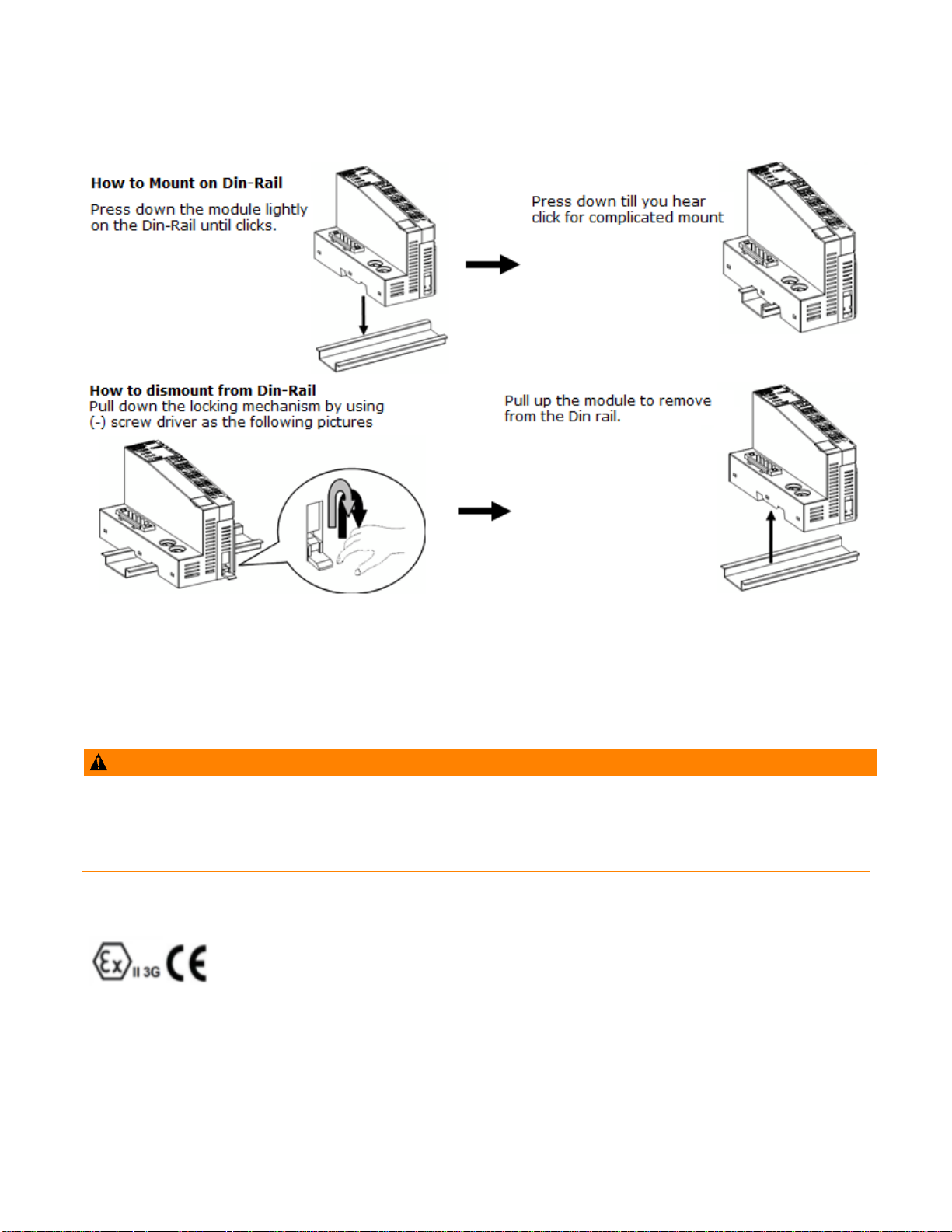
Module Mounting
Installation in Hazardous Area
UL Class 1 Division 2 & ATEX Zone 2 Hazardous Area Warnings
• EQUIPMENT LABELED WITH REFERENCE TO CLASS I, GROUPS A, B, C & D, DIV. 2 OR ZONE 2 HAZARDOUS
LOCATIONS IS SUITABLE FOR USE IN CLASS I, DIVISION 2, GROUPS A, B, C, D, ZONE 2 OR NON-HAZARDOUS
LOCATIONS ONLY.
WARNING
• EXPLOSION HAZARD–SUBSTITUTION OF COMPONENTS MAY IMPAIR SUITABILITY FOR CLASS I, DIVISION 2 &
ATEX ZONE2.
• EXPLOSION HAZARD – TURN OFF POWER BEFORE REPLACING OR WIRING MODULES. DO NOT CONNECT OR
DISCONNECT EQUIPMENT UNLESS POWER HAS BEEN SWITCHED OFF OR THE AREA IS KNOWN TO BE NON–
HAZARDOUS.
ATEX Information
Ambient Range: 0°C ≤ Tamb ≤ 55°C
Certification string: Ex nA IIC T4 Gc (Modules without Relay) & Ex nA nC IIC T4 Gc (Modules with Relay)
Standards Covered: EN 60079-0:2012, EN 60079-15:2010
Special Conditions for Safe Usage:
• The device shall be mounted in an ATEX certified enclosure with a minimum ingress protection rating of at least
IP54 as defined in IEC/EN 60529 and used in an area of not more that pollution degree 2 as defined by IEC60664-
1. Enclosure must utilize a tool removable cover or door.
Page 6

GFK-2771G Sep 2019
4
• Provisions shall be made to prevent the rated voltage being exceeded by the transient disturbances of more than
140%.
• Earthing is accomplished though mounting of modules in rail.
• Subject devices are for operation in Ambient Temperature Range: 0 °C to +55 °C.
LED Status Display
Item
LED is
State
To Indicate
Module Status
LED (MOD)
OFF
Power off
H/W Fault
No Power is supplied to the unit
Solid Red
Invalid boot image
header (Flash), ROM
Boot loader
The unit has occurred unrecoverable fault in selftesting.
- Firmware fault
Flashing Red
(0.5 Sec)
Invalid RAM Image
Invalid RAM Image
Flashing Red
(0.1 Sec)
OS Fatal error is
occurred
OS Fatal error is occurred
Flashing Green (0.1
Sec)
OS Handle Unexpected
Exceptions
OS Handle Unexpected Exceptions
Solid Green
Normal Operation
The unit is operating in normal condition.
NET LED
Off
Power off No
Connection has Been
established with IOcontroller.
Device is not on-line or may not be powered
Flashing Red (0.1 Sec)
Invalid Configuration
Invalid Configuration
Flashing Green (0.1 Sec)
Wait parameters
PROFINET I/O connection has been established.
Wait parameters
Solid Red
PROFINET I/O connection is aborted after a data
exchange has taken place.
Flashing Red (0.5 Sec)
PROFINET I/O connection is aborted before a
data exchange has taken place
Flashing Green (0.5 Sec)
PROFINET I/O Data Exchange stop
Solid Green
PROFINET I/O Data Exchange Run
I/O LED
I/O LED
Off
Not Powered No I/O
Module
Device has no I/O module or may not be powered
Flashing Green
Bus On-line, Do not
Exchanging I/O
Bus operation is normal but does not
exchanging I/O data (Passed the I/O module
configuration).
Solid Green
Bus Connection, Run
Exchanging IO
Exchanging I/O data
Solid Red
Bus connection fault
during exchanging IO
One or more I/O module occurred in fault state.
Changed IO module configuration. Bus
communication failure.
Flashing Red
I/O Configuration Failed
Failed to initialize I/O module - Detected invalid
IO module ID. - Overflowed Input / Output Size Too many I/O module - Initial protocol failure
Port1
Port2
LED
Solid Green
Link is up (Physical connection is established)
Flashing Green
Active is present
Off Link isdown
Field
Power LED
Off
Not Supplied Field
Power
Not Supplied 24Vdc field Power
Solid Green
Supplied Field Power
Supplied 24Vdc field power
Page 7
GFK-2771G Sep 2019
5
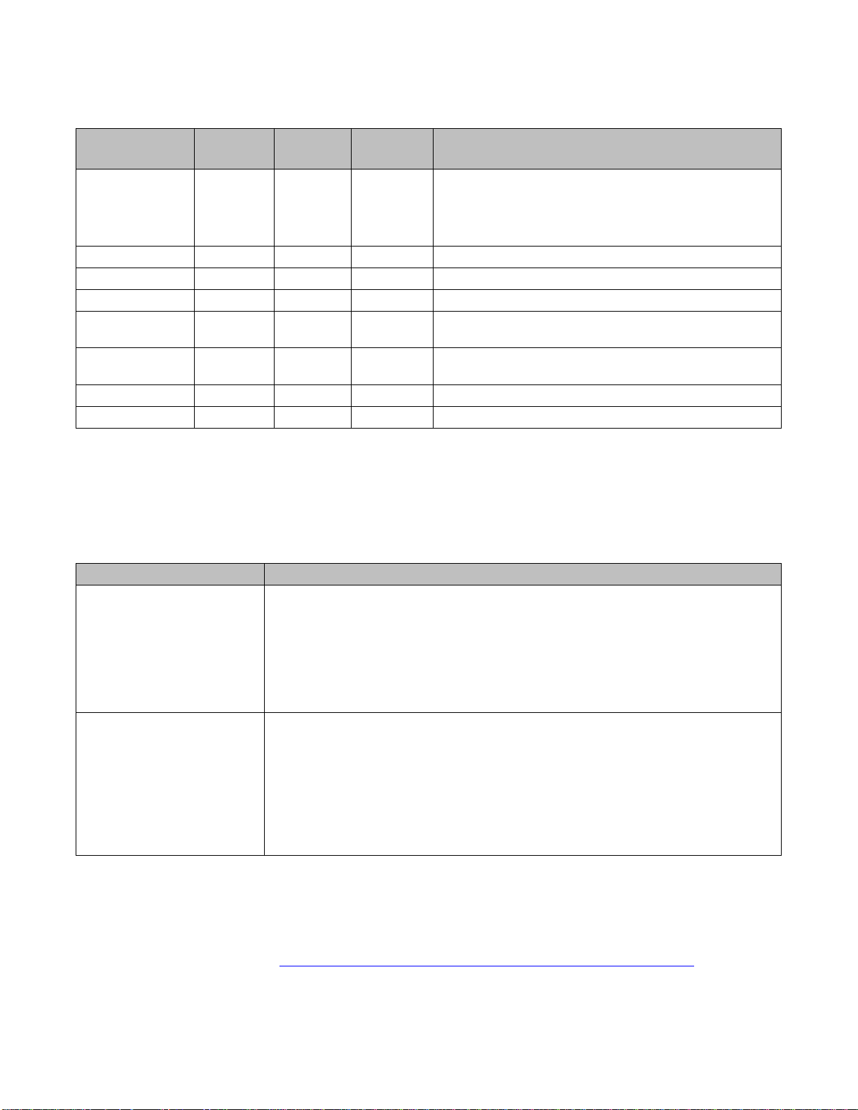
Release Information
Part Number
Hardware
Version
Firmware
Version
Date
Remarks
STXPNS001-DE
20.02
20.220
Sep 2019
Following Emerson’s acquisition of this product, changes
have been made to apply appropriate branding and
registration of the product with required certification
agencies. No changes to material, process, form, fit or
functionality.
STXPNS001-CE
20.02
20.220
May 2019
Firmware updates. No change in form-fit-functionality.
STXPNS001-CD
20.02
20.210
Apr 2019
Firmware updates. No change in form-fit-functionality.
STXPNS001-CC
20.02
20.100
Feb 2016
Firmware updates. No change in form-fit-functionality.
STXPNS001-BC
20.01
20.100
Nov 2013
Atex & Hazloc certification documentation updates. No
change in form-fit-functionality.
STXPNS001-AC
20.00
20.100
Mar 2013
Firmware updates to fix the bugs. No change in form-fitfunctionality.
STXPNS001-AB
20.00
20.010
Apr 2012
Firmware updates. No change in form-fit-functionality.
STXPNS001-AA
20.00
20.000
Mar 2012
Initial Release
Problems Resolved in this Release
None
New Features and Enhancements in this Release
None. Only documentation update.
Restrictions and Open Issues
Subject
Description
Clearing the RX3i controller
memory when a configuration
mismatch fault for a Slice I/O
node exists causes PACSystems
Machine Edition (PME) software
to disconnect and the RX3i
PNC001 to auto reset.
This fault can occur when an RX3i PNC module is connected to a Slice I/O node that has a
STXPNS001 Profinet Network Adapter and I/O modules. If there is a configuration mismatch
of the Slice IO node, a loss of device fault is logged in the I/O fault table. In this situation, if
you try to clear the RX3i CPU user memory, PME disconnects from the RX3i controller. After
the PME connection is lost, if you try to reconnect to the RX3i CPU,the RX3i PNCperforms an
auto reset. To recover from this fault, wait for the PNC to auto reset and the OK LED to glow
solid green, then clear the RX3i CPUuser memory or power cycle the RX3i controller
withoutbattery.Storingavalid configuration restores system operation without faults.
Slice I/O node system power up
sequence issue.
Ifthe NetworkAdapterandST-7xxxPower modules on the same Slice I/O node are
powercycledat differenttimes, the Network Adaptermaypowerup in faultmode. To recover
from the fault, power cycle the node such that Network Adapter andPower modules are
power cycled together or the node is powered up following the sequence such that the power
module farthest from the NetworkAdapterispowered up first. For examplein anode
havingmodules asbelow: STXPNS001+I/O Modules …+ST-7511+I/OModules … +ST7511+I/OModules In the above system power cycle the STXPNS001 and the two ST-7511
modules together or power OFF the entire node andthen powerONthe second ST-7511
andthen the firstST-7511 andthen the STXPNS001.
Upgrades with this release
None
Configuration
Download latest GSDML file from https://www.emerson.com/Industrial-Automation-Controls/support.
Page 8

GFK-2771G Sep 2019
6
Operational Notes
Subject
Description
Loss of device fault occurs when
STXPNS001 Profinet Network
Adaptor isused without I/O
module.
When the Slice I/O Profinet Network Adapter module does not have an I/O module attached,
it will not communicate with the RX3i PNC. The Network Adapter NET LED blinks RED,
indicating invalid configuration and a Loss of device fault is logged in RX3i I/O Fault table. At
least one I/O module has to be present for the NetworkAdapterto establishthe
communication withRX3i PNC.
Page 9

IMPORTANT PRODUCT INFORMATION
GFK-2771G
Sep 2019
Technical Support & Contact Information:
Home link: http://www.Emerson.com/Industrial-Automation-Controls
Knowledge Base: https://www.emerson.com/Industrial-Automation-Controls/support
Note: If the product is purchased through an Authorized Channel Partner, please contact the seller directly for any support.
Emerson reserves the right to modify or improve the designs or specifications of the products mentioned in this manual at any time without notice.
Emerson does not assume responsibility for the selection, use or maintenance of any product. Responsibility for proper select ion, use and
maintenance of any Emerson product remains solely with the purchaser.
© 2019 Emerson. All rights reserved.
Emerson Terms and Conditions of Sale are available upon request. The Emerson logo is a trademark and service mark of Emerson Electric Co. All
other marks are the property of their respective owners.
 Loading...