

Page 1

GE
Automation & Controls
Programmable Control Products
PACSystems* RX7i, RX3i
and RSTi-EP TCP/IP
Ethernet
Communications User
Manual
GFK-2224R
June 2017
Page 2

Page 3

Warnings, Cautions, and Notes as Used in this Publication
Warning
Warning notices are used in this publication to emphasize that hazardous
voltages, currents, temperatures, or other conditions that could cause personal
injury exist in this equipment or may be associated with its use.
In situations where inattention could cause either personal injury or damage to
equipment, a Warning notice is used.
Caution
Caution notices are used where equipment might be damaged if care is
not taken.
Note: Notes merely call attention to information that is especially significant to understanding
and operating the equipment.
These instructions do not purport to cover all details or variations in equipment, nor to provide for every
possible contingency to be met during installation, operation, and maintenance. The information is supplied for
informational purposes only, and GE makes no warranty as to the accuracy of the information included herein.
Changes, modifications, and/or improvements to equipment and specifications are made periodically and
these changes may or may not be reflected herein. It is understood that GE may make changes, modifications,
or improvements to the equipment referenced herein or to the document itself at any time. This document is
intended for trained personnel familiar with the GE products referenced herein.
GE may have patents or pending patent applications covering subject matter in this document. The furnishing
of this document does not provide any license whatsoever to any of these patents.
GE PROVIDES THE FOLLOWING DOCUMENT AND THE INFORMATION INCLUDED THEREIN AS-IS AND WITHOUT
WARRANTY OF ANY KIND, EXPRESSED OR IMPLIED, INCLUDING BUT NOT LIMITED TO ANY IMPLIED STATUTORY
WARRANTY OF MERCHANTABILITY OR FITNESS FOR PARTICULAR PURPOSE.
* Indicates a trademark of General Electric Company and/or its subsidiaries.
All other trademarks are the property of their respective owners.
Copyright © 2002-2017 General Electric Company. All Rights Reserved
Page 4

Contact Information
If you purchased this product through an Authorized Channel Partner, please contact the seller directly.
General Contact Information
Online technical support and GlobalCare
www.geautomation.com/support
Additional information
www.geautomation.com
Solution Provider
solutionprovider.ip@ge.com
Technical Support
If you have technical problems that cannot be resolved with the information in this manual, please contact us by
telephone , or on the web at www.geautomation.com/support
Americas
Phone
1-800-433-2682
International Americas Direct Dial
1-780-420-2010 (if toll free 800 option is unavailable)
Customer Care Email
customercare.ip@ge.com
Primary language of support
English
Europe, the Middle East, and Africa
Phone
+800-1-433-2682
EMEA Direct Dial
+420 239015850 (if toll free 800 option is unavailable or if
dialing from a mobile telephone)
Customer Care Email
customercare.emea.ip@ge.com
Primary languages of support
English, French, German, Italian, Czech, Spanish
Asia Pacific
Phone
+86-400-820-8208
+86-21-3877-7006 (India, Indonesia, and Pakistan)
Customer Care Email
customercare.apo.ip@ge.com
customercare.cn.ip@ge.com (China)
Primary languages of support
Chinese, Japanese, English
Page 5

GFK-2224R June 2017 iii
Table of Contents
Contact Information .......................................................................................................................................................... ii
Table of Contents .............................................................................................................................................................. iii
Table of Figures...................................................................................................................................................................xi
Chapter 1 Introduction ................................................................................................................................... 1
1.1 Revisions in this Manual ............................................................................................................................. 2
1.2 Other PACSystems Manuals....................................................................................................................... 2
1.3 Ethernet Interfaces for PACSystems Controllers ................................................................................... 3
Rack-based and RX7i Embedded Interfaces - Features ........................................................................... 3
RX3i & RSTi-EP Embedded Ethernet Interface - Features ........................................................................ 4
Ethernet Interface Specifications .......................................................................................................................... 5
Ethernet Interface Ports ............................................................................................................................................. 8
Station Manager ............................................................................................................................................................. 9
Firmware Upgrades ...................................................................................................................................................... 9
Built-In Web Server ....................................................................................................................................................... 9
SRTP Client (Channels) ................................................................................................................................................. 9
Modbus TCP Client (Channels) ................................................................................................................................. 9
Ethernet Global Data (EGD) .................................................................................................................................... 10
SRTP Inactivity Timeout ........................................................................................................................................... 10
1.4 Ethernet Redundancy Operation ............................................................................................................ 11
HSB CPU Redundancy .............................................................................................................................................. 11
Non-HSB Redundancy ............................................................................................................................................. 12
Effect of Redundancy Role Switching on Ethernet Communications ............................................. 12
SRTP Server Operation in a Redundancy System ...................................................................................... 13
SRTP Client Operation in a Redundancy System........................................................................................ 14
Modbus TCP Server Operation in a Redundancy System ...................................................................... 14
Modbus TCP Client Operation in a Redundancy System ....................................................................... 14
EGD Class 1 (Production & Consumption) in a Redundancy System ............................................... 14
EGD Class 2 Commands in a Redundancy System .................................................................................. 14
Web Server Operation in a Redundancy System ....................................................................................... 15
FTP Operation in a Redundancy System ........................................................................................................ 15
SNTP Operation in a Redundancy System .................................................................................................... 15
Remote Station Manager Operation in a Redundancy System ......................................................... 15
IP Address Configuration in a Redundancy System ................................................................................. 15
Chapter 2 Installation and Start-up: RX3i/RSTi-EP Embedded Interface ............................................ 16
2.1 RX3i/RSTi-EP Embedded Ethernet Interface Indicators ...................................................................... 16
Ethernet Port LEDs Operation .............................................................................................................................. 16
Module Installation .................................................................................................................................................... 17
Page 6

Contents
iv PACSystems* RX7i, RX3i and RSTi-EP TCP/IP Ethernet Communications User Manual GFK-2224R
2.2 Ethernet Port Connector ........................................................................................................................... 18
Connection to a 10Base-T / 100Base Tx Network .................................................................................... 18
10Base-T/100Base Tx Port Pinouts ................................................................................................................... 18
2.3 Pinging TCP/IP Ethernet Interfaces on the Network ........................................................................... 19
Pinging the Ethernet Interface from a UNIX Host or Computer Running TCP/IP Software . 19
Determining if an IP Address is Already Being Used ................................................................................ 19
Chapter 3 Installation and Start-up: Rack-based and RX7i Embedded Interface ............................. 20
3.1 Ethernet Interface Controls and Indicators .......................................................................................... 21
Ethernet LEDs ................................................................................................................................................................ 21
Ethernet Restart Pushbutton ................................................................................................................................ 23
3.2 Module Installation .................................................................................................................................... 24
Installing an RX7i CPU with Embedded Ethernet Interface .................................................................. 24
Installing an RX7i Ethernet Interface Module............................................................................................... 24
Installing an RX3i Ethernet Interface Module............................................................................................... 25
3.3 Ethernet Port Connectors ......................................................................................................................... 26
Embedded Switch ....................................................................................................................................................... 26
Connection to a 10Base-T / 100Base Tx Network .................................................................................... 27
3.4 Station Manager Port ................................................................................................................................ 29
Port Settings .................................................................................................................................................................. 29
3.5 Verifying Proper Power-Up of the Ethernet Interface after Configuration ..................................... 30
3.6 Pinging TCP/IP Ethernet Interfaces on the Network ........................................................................... 30
Pinging the Ethernet Interface from a UNIX Host or Computer Running TCP/IP Software . 30
Determining if an IP Address is Already Being Used ................................................................................ 31
3.7 Ethernet Plug-in Applications .................................................................................................................. 31
Chapter 4 Configuration ............................................................................................................................... 33
4.1 RX3i/RSTi-EP Embedded Ethernet Interfaces ....................................................................................... 33
Ethernet Configuration Data ................................................................................................................................ 33
Initial IP Address Assignment ............................................................................................................................... 34
Configuring the Ethernet Interface Parameters ......................................................................................... 35
4.2 Rack-based and RX7i Embedded Interfaces ......................................................................................... 48
Ethernet Configuration Data ................................................................................................................................ 48
Initial IP Address Assignment ............................................................................................................................... 49
Configuring Ethernet Interface Parameters ................................................................................................. 52
Configuring Ethernet Global Data ...................................................................................................................... 55
Chapter 5 Ethernet Global Data .................................................................................................................. 69
5.1 Ethernet Global Data Operation ............................................................................................................. 70
EGD Producer ................................................................................................................................................................ 70
Page 7

Contents
GFK-2224R June 2017 v
EGD Consumers ........................................................................................................................................................... 70
5.2 EGD Exchanges ........................................................................................................................................... 71
Content of an Ethernet Global Data Exchange........................................................................................... 71
Data Ranges (Variables) in an Ethernet Global Data Exchange ........................................................ 71
Valid Memory Types for Ethernet Global Data ............................................................................................ 72
Planning Exchanges .................................................................................................................................................. 72
Using Ethernet Global Data in a Redundancy System ............................................................................ 73
5.3 Sending an Ethernet Global Data Exchange to Multiple Consumers ............................................... 73
Multicasting Ethernet Global Data .................................................................................................................... 73
Broadcasting Ethernet Global Data .................................................................................................................. 74
Changing Group ID in Run Mode ........................................................................................................................ 74
5.4 Ethernet Global Data Timing ................................................................................................................... 75
EGD Synchronization ................................................................................................................................................ 75
Configurable Producer Period for an EGD Exchange .............................................................................. 76
Consumer Update Timeout Period .................................................................................................................... 76
5.5 Time-Stamping of Ethernet Global Data Exchanges ........................................................................... 77
Obtaining Timestamps from the Ethernet Interface Clock ................................................................... 78
Obtaining Timestamps from the CPU TOD Clock ....................................................................................... 79
SNTP Operation ............................................................................................................................................................ 86
5.6 Effect of PLC Modes and Actions on EGD Operations ......................................................................... 88
Run Mode Store of EGD ........................................................................................................................................... 89
5.7 Monitoring Ethernet Global Data Exchange Status ............................................................................ 92
Exchange Status Word Error Codes.................................................................................................................. 93
Chapter 6 Programming EGD Commands ................................................................................................ 94
6.1 General Use of EGD Commands .............................................................................................................. 94
6.2 Using EGD Commands in a Redundancy System ................................................................................. 94
6.3 COMMREQ Format for Programming EGD Commands ...................................................................... 94
6.4 COMMREQ Status for the EGD Commands ........................................................................................... 95
COMMREQ Status Values ........................................................................................................................................ 95
6.5 Read PLC Memory (4000) .......................................................................................................................... 96
Read PLC Memory Command Block ................................................................................................................. 96
6.6 Write PLC Memory (4001) ......................................................................................................................... 99
Write PLC Memory Command Block................................................................................................................. 99
6.7 Read EGD Exchange (4002) ..................................................................................................................... 101
Read EGD Exchange Command Block ..........................................................................................................101
Page 8

Contents
vi PACSystems* RX7i, RX3i and RSTi-EP TCP/IP Ethernet Communications User Manual GFK-2224R
6.8 Write EGD Exchange (4003) .................................................................................................................... 104
Write EGD Exchange Command Block ..........................................................................................................104
6.9 Masked Write to EGD Exchange (4004) ................................................................................................ 106
Masked Write EGD Exchange Command Block ........................................................................................106
Chapter 7 Programming SRTP Channel Commands ............................................................................. 110
7.1 SRTP Channel Commands ...................................................................................................................... 110
Channel Operations .................................................................................................................................................111
Aborting and Re-tasking a Channel ................................................................................................................111
Monitoring the Channel Status ..........................................................................................................................111
SRTP Channel Commands in a Redundant System ................................................................................111
Executing a Channel Command .......................................................................................................................112
7.2 COMMREQ Format for Programming Channel Commands ............................................................. 113
The COMMREQ Command Block: General Description .........................................................................114
Establish Read Channel (2003) ..........................................................................................................................116
Establish Write Channel (2004) ..........................................................................................................................120
Send Information Report (2010) ........................................................................................................................123
Abort Channel (2001) ..............................................................................................................................................125
Retrieve Detailed Channel Status (2002) ......................................................................................................126
7.3 Programming for Channel Commands ................................................................................................ 127
COMMREQ Sample Logic ......................................................................................................................................128
Sequencing Communications Requests .......................................................................................................130
Managing Channels and TCP Connections .................................................................................................130
Use “Channel Re-Tasking” To Avoid Using Up TCP Connections .....................................................131
Client Channels TCP Resource Management ............................................................................................131
SRTP Application Timeouts ..................................................................................................................................132
7.4 Monitoring Channel Status .................................................................................................................... 132
Format of the COMMREQ Status Word .........................................................................................................132
Chapter 8 Modbus/TCP Server .................................................................................................................. 135
8.1 Modbus/TCP Server ................................................................................................................................. 135
Modbus/TCP Server Connections .....................................................................................................................135
Modbus Conformance Classes ..........................................................................................................................135
Server Protocol Services........................................................................................................................................135
Station Manager Support .....................................................................................................................................135
8.2 Reference Mapping .................................................................................................................................. 136
Modbus Reference Tables ....................................................................................................................................136
Address Configuration ...........................................................................................................................................137
Page 9

Contents
GFK-2224R June 2017 vii
8.3 Modbus Function Codes.......................................................................................................................... 138
Chapter 9 Modbus/TCP Client ................................................................................................................... 139
9.1 The Communications Request ............................................................................................................... 139
Structure of the Communications Request ................................................................................................140
COMMREQ Function Block ...................................................................................................................................140
COMMREQ Command Block................................................................................................................................140
Modbus/TCP Channel Commands ...................................................................................................................141
Status Data ..................................................................................................................................................................141
Operation of the Communications Request ...............................................................................................142
9.2 COMMREQ Function Block and Command Block ............................................................................... 143
The COMMREQ Function Block ..........................................................................................................................143
The COMMREQ Command Block ......................................................................................................................144
9.3 Modbus/TCP Channel Commands ........................................................................................................ 145
Open a Modbus/TCP Client Connection (3000) .........................................................................................145
Close a Modbus/TCP Client Connection (3001) .........................................................................................147
Read Data from a Modbus/TCP Device (3003) ..........................................................................................148
Write Data to a Modbus/TCP Device (3004)................................................................................................154
Mask Write Register Request to a Modbus Server Device (3009) ....................................................158
Read/Write Multiple Registers to/from a Modbus Server Device (3005) .....................................159
9.4 Status Data ............................................................................................................................................... 161
Types of Status Data ...............................................................................................................................................161
9.5 Controlling Communications in the Ladder Program ....................................................................... 162
Essential Elements of the Ladder Program .................................................................................................162
COMMREQ Ladder Logic Example ...................................................................................................................163
Troubleshooting a Ladder Program ................................................................................................................169
Monitoring the Communications Channel ..................................................................................................170
9.6 Differences between Series 90 and PACSystems Modbus/TCP Channels ..................................... 171
Chapter 10 OPC UA Server ........................................................................................................................... 173
10.1 Application Logic to Control the OPC UA Server ................................................................................ 174
OPC UA Server Service Request ........................................................................................................................174
OPC UA Server Subroutine ...................................................................................................................................182
Connect OPC UA Client to OPC UA Server....................................................................................................184
OPC UA Client Authentication Settings .........................................................................................................187
Anonymous Authentication.................................................................................................................................187
Username/Password Authentication .............................................................................................................188
OPC UA Security Settings ......................................................................................................................................190
OPC UA Address Space ..........................................................................................................................................190
Publish Application Variables to OPC UA Address Space ....................................................................191
OPC UA Server Information in Address Space...........................................................................................192
OPC UA Server – Application Information ....................................................................................................194
Page 10

Contents
viii PACSystems* RX7i, RX3i and RSTi-EP TCP/IP Ethernet Communications User Manual GFK-2224R
OPC UA Server – GE Device Information ......................................................................................................195
OPC UA Automatic Restart Function ..............................................................................................................196
OPC UA Server Certificates ..................................................................................................................................196
OPC UA Performance Considerations ............................................................................................................197
Sessions and Subscriptions for OPC UA ........................................................................................................197
Chapter 11 RX7i PLC Monitoring Via the Web .......................................................................................... 199
11.1 System Requirements ............................................................................................................................. 199
11.2 Disabling Pop-up Blocking ..................................................................................................................... 199
11.3 Web Server Operation in a Redundant System .................................................................................. 199
11.4 Standard Web Pages ............................................................................................................................... 199
RX7i Home Page ........................................................................................................................................................200
Factory Default Web Page ...................................................................................................................................200
Reference Tables Viewer Page ..........................................................................................................................200
PLC Fault Table Viewer Page ..............................................................................................................................202
I/O Fault Table Viewer Page ................................................................................................................................204
11.5 Downloading PLC Web Pages ................................................................................................................ 204
FTP Connect and Login ..........................................................................................................................................204
Changing the Password ........................................................................................................................................205
Web Page File Transfer ..........................................................................................................................................205
11.6 Viewing the RX7i PLC Web Pages .......................................................................................................... 206
Chapter 12 Diagnostics................................................................................................................................. 207
12.1 What to do if You Cannot Solve the Problem ...................................................................................... 207
12.2 Diagnostic Tools Available for Troubleshooting ................................................................................ 208
12.3 States of the Ethernet Interface (Rack-based and RX7i Embedded Interfaces) ........................... 209
12.4 EOK LED Blink Codes for Hardware Failures (Rack-based and RX7i Embedded Interfaces) ...... 211
12.5 Controller Fault Table ............................................................................................................................. 212
Controller Fault Table Descriptions .................................................................................................................212
12.6 Monitoring the Ethernet Interface Status Bits ................................................................................... 214
217
LAN Interface Status (LIS) Bits ............................................................................................................................218
Channel Status Bits ..................................................................................................................................................219
12.7 Monitoring the FT Output of the COMMREQ Function Block. .......................................................... 220
12.8 Monitoring the COMMREQ Status Word .............................................................................................. 220
Format of the COMMREQ Status Word .........................................................................................................221
Major Error Codes in the COMMREQ Status Word...................................................................................222
Minor Error Codes for Major Error Codes 05H (at Remote Server PLC) and 85H (at Client PLC)
............................................................................................................................................................................................223
Page 11

Contents
GFK-2224R June 2017 ix
Minor Error Codes for Major Error Code 11H (at Remote Server PLC) ...........................................225
Minor Error Codes for Major Error Code 90H (at Client PLC) ..............................................................227
Minor Error Codes for Major Error Code 91H (at Remote Modbus/TCP Server) .......................229
Minor Error Codes for Major Error Code A0H (at Client PLC) ..............................................................230
12.9 Using the EGD Management Tool (Rack-based and RX7i Embedded) ............................................ 231
Installing the EGD Management Tool ............................................................................................................231
Launching the EGD Management Tool .........................................................................................................231
Monitoring EGD Devices ........................................................................................................................................232
Monitoring Status of Ethernet Global Data for a Device......................................................................233
12.10 Troubleshooting Common Ethernet Difficulties ................................................................................ 235
COMMREQ Fault Errors ..........................................................................................................................................235
PLC Timeout Errors ...................................................................................................................................................236
Application Timeout Errors ..................................................................................................................................237
EGD Configuration Mismatch Errors ...............................................................................................................237
Station Manager Lockout under Heavy Load ............................................................................................238
PING Restrictions .......................................................................................................................................................238
SRTP and Modbus/TCP Connection Timeout .............................................................................................238
Sluggish Programmer Response after Network Disruption ...............................................................239
EGD Command Session Conflicts .....................................................................................................................239
SRTP Request Incompatibility with Existing Host Communications Toolkit Devices or Other
SRTP Clients..................................................................................................................................................................239
COMMREQ Flooding Can Interrupt Normal Operation ..........................................................................239
Accelerated EGD Consumption Can Interfere with EGD Production .............................................240
Channels Operation Depends Upon PLC Input Scanning ...................................................................240
Chapter 13 Network Administration .......................................................................................................... 243
13.1 IP Addressing ............................................................................................................................................ 243
IP Address Format for Network Classes A, B, C .........................................................................................243
IP Addresses Reserved for Private Networks .............................................................................................244
Multicast IP Addresses ...........................................................................................................................................244
Loopback IP Addresses ..........................................................................................................................................244
Overlapping Subnets ..............................................................................................................................................244
13.2 Gateways ................................................................................................................................................... 247
Networks Connected by a Gateway ...............................................................................................................247
13.3 Subnets and Supernets ........................................................................................................................... 247
Subnet Addressing and Subnet Masks ..........................................................................................................248
Appendix A Configuring Advanced User Parameters .............................................................................................. 253
A-1 Format of the Advanced User Parameters File .................................................................................. 254
A-2 Advanced User Parameter Definitions ................................................................................................ 256
A-3 AUPs Supported by RX3i CPE305/CPE310 Embedded Ethernet Interface ..................................... 263
Page 12

Page 13

GFK-2224R June 2017 xi
Table of Figures
Figure 1: Ethernet Connection System Diagram.............................................................................................................................................. 3
Figure 2: Ethernet Operation in Redundancy Mode .................................................................................................................................... 11
Figure 3: Basic non-HSB System with Redundant IP .................................................................................................................................. 12
Figure 4: RJ-45 Connector ....................................................................................................................................................................................... 18
Figure 5: Ethernet Cable Routing .......................................................................................................................................................................... 19
Figure 6: RX7i Faceplate ........................................................................................................................................................................................... 21
Figure 7: MAC Address on RX7i ............................................................................................................................................................................. 24
Figure 8: MAC Address on RX3i ETM001 Module .......................................................................................................................................... 25
Figure 9: Diagram of Embedded Ethernet Switch ........................................................................................................................................ 26
Figure 10: System Diagram: Ethernet Routing Using Embedded Switch ......................................................................................... 26
Figure 11: Connection Using Hub/Switch/Repeater ................................................................................................................................... 28
Figure 12: Direct Connection to the Embedded Ethernet Ports............................................................................................................. 29
Figure 13: Expand CPU Slot to Display Ethernet Node .............................................................................................................................. 34
Figure 14: Expand RX3i CPU Node to Configure Embedded Ethernet Interface ........................................................................... 36
Figure 15: Ethernet Settings Tab in Proficy Machine Edition .................................................................................................................. 37
Figure 16: CPE330/CPE400/CPE100 settings tab ........................................................................................................................................ 40
Figure 17: CPE330 Advanced Ethernet Configuration LAN 1 & 2 ......................................................................................................... 41
Figure 18: CPE400/CPE100 Advanced Ethernet Configuration LAN1 & LAN 2 ............................................................................. 42
Figure 19: Terminals Tab Settings in Proficy Machine Edition ............................................................................................................... 43
Figure 20: Adding Ethernet Global Data (EGD) to the Configuration .................................................................................................. 44
Figure 21: Defining EGD Produced Data Exchange .................................................................................................................................... 44
Figure 22: Defining EGD Consumed Data Exchange .................................................................................................................................. 45
Figure 23: Configuring Multicast & Broadcast EGD on LAN 1 ................................................................................................................ 46
Figure 24: Configuring Multicast & Broadcast EGD on LAN 2 ................................................................................................................ 47
Figure 25: Setting Temporary IP Address ......................................................................................................................................................... 50
Figure 26: Expand RX7i CPU Node to Configure Ethernet Daughterboard ..................................................................................... 52
Figure 27: Install ETM001 Module in Rack/Slot & Expand to Configure .......................................................................................... 52
Figure 28: Expand Node to View Ethernet Global Data ............................................................................................................................ 55
Figure 29: Local Producer ID ................................................................................................................................................................................... 55
Figure 30: Configuring Redundancy for Ethernet Global Data .............................................................................................................. 56
Figure 31: Exchange ID Offset in an Ethernet Redundancy System ................................................................................................... 56
Figure 32: Configuring Produce in Backup Mode Parameter ................................................................................................................. 57
Figure 33: Configuring the EGD Configuration Server ............................................................................................................................... 58
Figure 34: Producing & Consuming Ethernet Global Data ...................................................................................................................... 70
Figure 35: Adding Symbolic Reference to Ethernet Global Data Exchange .................................................................................... 72
Figure 36: Grouping of Devices for Ethernet Global Data Multicasting ............................................................................................ 73
Figure 37: Memory Sharing between PLC and Ethernet Interface ...................................................................................................... 75
Figure 38: EGB Timing Example #1 ..................................................................................................................................................................... 76
Figure 39: EGB Timing Example #2 ..................................................................................................................................................................... 77
Figure 40: Obtaining Timestamps from the Ethernet Interface Clock ................................................................................................ 78
Figure 41: Obtaining Timestamps from the PLC Time Clock .................................................................................................................. 78
Figure 42: Obtaining Timestamps from the SNTP Server’s Time Clock ............................................................................................. 79
Figure 43: Synchronizing CPU Time-of-Day Clock to an SNTP Server................................................................................................ 80
Page 14

Contents
xii PACSystems* RX7i, RX3i and RSTi-EP TCP/IP Ethernet Communications User Manual GFK-2224R
Figure 44: Operating Sequence for CPU Clock Synchronization ........................................................................................................... 81
Figure 45: COMMREQ to Control the CPU Time-of-Day Clock ................................................................................................................ 82
Figure 46: COMMREQ Used to Program Ethernet Global Data ............................................................................................................. 94
Figure 47: Example: Masked Write to EGD Exchange Bit Mask and Data Bits ............................................................................108
Figure 48: COMMREQ Sequence for Establish Read Channel ..............................................................................................................112
Figure 49: COMMREQ for Programming Channel Commands ............................................................................................................113
Figure 50: Interpreting Detailed Channel Status Words .........................................................................................................................127
Figure 51: Sample Ladder Logic for COMMREQ ..........................................................................................................................................129
Figure 52: Interpreting COMMREQ Status Word .........................................................................................................................................132
Figure 53: Calculations for Modbus File and Record %W Memory Address .................................................................................136
Figure 54: Phases of a COMMREQ Execution ...............................................................................................................................................140
Figure 55: Illustration of Phased Operation of a COMMREQ .................................................................................................................142
Figure 56: The COMMREQ Function Block ......................................................................................................................................................143
Figure 57: Interpreting the COMMREQ Status Word .................................................................................................................................162
Figure 58: COMMREQ Ladder Logic Segment ..............................................................................................................................................163
Figure 59: COMMREQ Ladder Logic Segment (continued) .....................................................................................................................164
Figure 60: COMMREQ Ladder Logic Segment (continued) .....................................................................................................................165
Figure 61: COMMREQ Ladder Logic Segment (continued) .....................................................................................................................166
Figure 62: COMMREQ Ladder Logic Segment (continued) .....................................................................................................................167
Figure 63: COMMREQ Ladder Logic Segment (continued) .....................................................................................................................167
Figure 64: COMMREQ Ladder Logic Segment (continued) .....................................................................................................................168
Figure 65: SERVER_STATUS Word bit definitions ........................................................................................................................................179
Figure 66: CONFIG_STATUS Word bit definitions .......................................................................................................................................181
Figure 67: OPC UA Example Subroutine .........................................................................................................................................................183
Figure 68: Project Inspector/Ethernet Config Window ............................................................................................................................185
Figure 69: OPC UA Server Client Connection String ..................................................................................................................................186
Figure 70: OPC UA Client Connection Dialog ................................................................................................................................................186
Figure 71: Machine Edition Controller Hardware Configuration – Passwords Disabled ........................................................187
Figure 72: Machine Edition Controller Hardware Configuration – Passwords Enabled .........................................................188
Figure 73: Machine Edition Online Command to Set Passwords .......................................................................................................189
Figure 74: OPC UA Connection Security Settings .......................................................................................................................................190
Figure 75: Example OPC UA Address Space .................................................................................................................................................190
Figure 76: Machine Edition Variable Inspector ............................................................................................................................................191
Figure 77: Application Variable Address Space ...........................................................................................................................................192
Figure 78: OPC UA Address Space - Server Node.......................................................................................................................................192
Figure 79: Server Specific Address Space ......................................................................................................................................................193
Figure 80: BuildInfo Subscription ........................................................................................................................................................................193
Figure 81: OPC UA Address Space - Application Information ..............................................................................................................194
Figure 82: OPC UA Address Space – GE Device Information ................................................................................................................195
Figure 83: PACSystems Factory Default Web Page ...................................................................................................................................200
Figure 84: Selecting Display Format .................................................................................................................................................................200
Figure 85: PLC Fault Table Display ....................................................................................................................................................................202
Figure 86: Fault Extra Data Display ...................................................................................................................................................................203
Figure 87: I/O Fault Table Display ......................................................................................................................................................................204
Figure 88: States of the Ethernet Interface ....................................................................................................................................................209
Figure 89: Fault Extra Data Example ................................................................................................................................................................212
Figure 90: Monitoring FT Output in COMMREQ Function Block...........................................................................................................220
Page 15

Contents
GFK-2224R June 2017 xiii
Figure 91: Decoding the COMMREQ Status Word ......................................................................................................................................221
Figure 92: EGD Management Tool Screenshot ............................................................................................................................................231
Figure 93: EGD Monitoring Tool Monitoring EGD Network ....................................................................................................................232
Figure 94: EGD Management Tool Displaying EGD Exchange Information ..................................................................................233
Figure 95: EGD Management Tool Displaying EGD Statistics ..............................................................................................................234
Figure 96: EGD Management Tool Displaying List of Variables for an Exchange ......................................................................235
Figure 97: IP Address Format for Network Classes A, B, C ....................................................................................................................243
Figure 98: CPE330 Overlapping Local IP Subnet Example ....................................................................................................................245
Figure 99: Expected Response Path ..................................................................................................................................................................246
Figure 100: Actual Response Path .....................................................................................................................................................................246
Figure 101: Gateway Connected to Two Networks ..................................................................................................................................247
Figure 102: Class B Network netid and hostid Bit Formats ...................................................................................................................248
Figure 103: Use of Subnet Mask .........................................................................................................................................................................248
Figure 104: Network 2 Divided into Subnets 2.1 and 2.2 .......................................................................................................................249
Figure 105: Subnet Mask Used to Effect a Supernet .................................................................................................................................250
Figure 106: Resulting Supernet ...........................................................................................................................................................................250
Page 16

Page 17

GFK-2224R June 2017 1
Chapter 1 Introduction
This chapter includes basic information about Ethernet Interfaces for the PACSystems family of controllers. It
describes features of the Ethernet Interfaces in both conventional and redundancy systems. The rest of this
manual provides instructions for installing and applying the PACSystems Ethernet Interfaces:
Chapter 2, Installation and Startup: RX3i & RSTi-EP Embedded Interfaces describes user features and basic
installation procedures.
Chapter 3, Installation and Startup: Rack-based and RX7i Embedded Interfaces describes user features and
basic installation procedures.
Chapter 4, Configuration describes assigning a temporary IP address and configuring the Ethernet interface
parameters. For the rack-based and RX7i embedded interfaces, describes how to configure Ethernet Global
Data (EGD) and set up the RS-232 port for Local Station Manager operation.
Chapter 5, Ethernet Global Data describes basic EGD operation for rack-based and RX7i embedded interfaces.
Chapter 6, EGD Commands describes a set of commands that can be used in the application program to read
and write PLC data or Ethernet Global Data exchange data over the network.
Chapter 7, Programming SRTP Channel Commands explains how to implement PLC to PLC communications
over the Ethernet network using Service Request Transfer Protocol (SRTP) Channel commands.
Chapter 8, Modbus TCP Server describes the implementation of the Modbus TCP Server feature for the
PACSystems family of products.
Chapter 9, Modbus TCP Client explains how to program communications over the Ethernet network using
Modbus TCP Channel commands.
Chapter 10, OPC UA Server, explains how to program communications for this protocol using the embedded
Ethernet port.
Chapter 11, RX7i PLC Monitoring Via the Web describes the Web browser feature provided by a PACSystems
RX7i CPU with Embedded Ethernet.
Chapter 12, Diagnostics describes diagnostic techniques for a PACSystems Ethernet Interface. This chapter also
lists COMMREQ Status codes.
Chapter 13, Network Administration discusses how devices are identified on the network and how data is
routed among devices.
Appendix A, Configuring Advanced User Parameters describes optional configuration of internal operating
parameters used by the Ethernet interface. For most applications, the default Advanced User Parameters (AUPs)
should not be changed.
Note: The RX3i CPE305/CPE310/CPE400 and RSTi-EP CPE100 embedded Ethernet interface
provides a maximum of two programmer connections. It does not support the full set of
features described in this manual. For a summary of RX3i CPE305/CPE310 embedded
Ethernet interface features, refer to Section 1.3.2. For a summary of RX3i CPE330/CPE400
and RSTi-EP CPE100 embedded Ethernet interface features, refer to Section 1.3.3.
Page 18

Chapter 1. Introduction
2 PACSystems* RX7i, RX3i and RSTi-EP TCP/IP Ethernet Communications User Manual GFK-2224R
1.1 Revisions in this Manual
Note: A given feature may not be implemented on all PACSystems Ethernet interfaces. To
determine whether a feature is available on a given model and firmware version, please
refer to the Important Product Information (IPI) document provided with the product.
This revision of TCP/IP Ethernet Communications for PACSystems RX3i, RX7i and RSTi-EP includes the following
changes:
Information about the following new features for the CPE305/CPE310/CPE400/CPE100 embedded Ethernet
interface:
Rev
Date
Description
R
May2017
• Content added in support of RSTi-EP CPE100
Q
Mar2017
• Content added in support of CPE400 and embedded SNTP
P
Sept2015
• Added section 10.1.16 on Sessions and Subscriptions for OPC UA
• Content added in support of CPE330 (new product)
M
Oct2014
• Effective with RX3i CPE305/CPE310 firmware version 8.20, OPC UA Server is supported
using the embedded Ethernet port.
• Effective with RX3i CPE305/CPE310 firmware version 8.30, EGD Class 1 is supported on
the embedded Ethernet Interface. Earlier CPU versions do not directly support EGD.
However, EGD was supported on the Ethernet Interface Module ETM001.
L
Jun2013
Newly available features:
• TCP/IP communication services using SRTP
• SRTP Client (Channels)
• Modbus/TCP Server, supporting Modbus Conformance classes 0, 1, and 2.
• Modbus/TCP Client, supporting Modbus Conformance classes 0, 1, and Function Codes
15, 22, 23, and 24 for Conformance class 2.
• Support for Unicast mode, and Daylight Saving and Local Time corrections for SNTP
operation.
Diagnostics information for the RX3i embedded Ethernet interface has been moved from
Chapter 2 to Chapter 12. Configuration information has been moved to Chapter 4.
Information about Channel Status bits has been removed from chapters 2, 7 and 9, and
consolidated in Chapter 12.
1.2 Other PACSystems Manuals
The manuals listed below provide more information about the PACSystems family of products.
▪ GFK-1918, Proficy* Logic Developer-PLC Getting Started
▪ GFK-2222, PACSystems CPU Reference Manual
▪ GFK-2223, PACSystems RX7i Installation Manual
▪ GFK-2225, TCP/IP Ethernet Communications for PACSystems Station Manager Manual
▪ GFK-2308, PACSystems Hot Standby CPU Redundancy User’s Guide
▪ GFK-2314, PACSystems RX3i System Manual
▪ GFK-2439, PACSystems RX3i Ethernet NIU User Manual
Page 19
Chapter 1. Introduction
GFK-2224R June 2017 3
▪ GFK-2741, PACSystems RX3i and RX7i Controllers Battery Manual
In addition to these manuals, datasheets and Important Product Information documents describe individual
modules and product revisions. The most recent PACSystems documentation is available online on the Support
website.
1.3 Ethernet Interfaces for PACSystems Controllers
A PACSystems Ethernet Interface enables a PACSystems controller to communicate with other PACSystems
equipment and with Series 90 and VersaMax controllers. The Ethernet Interface provides TCP/IP
communications with other PLCs, host computers running the Host Communications Toolkit or CIMPLICITY
software, and computers running the TCP/IP version of the programming software. These communications use
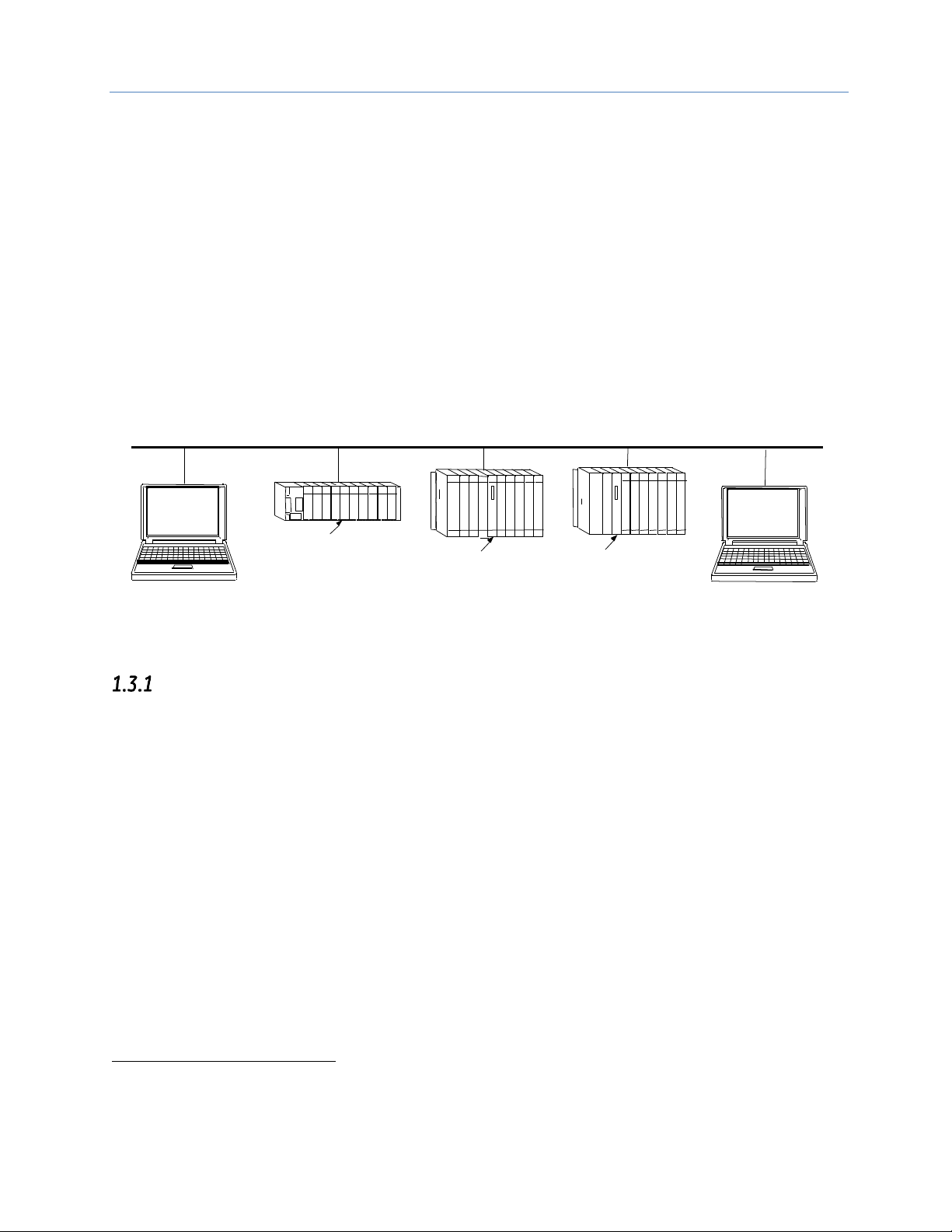
the proprietary SRTP and Ethernet Global Data (EGD)1 protocols over a four-layer TCP/IP (Internet) stack.
The Ethernet Interface has SRTP client/server capability. As a client, the Interface can initiate communications
with other PLCs that contain Ethernet Interfaces. This is done from the PLC ladder program using the COMMREQ
function. As a server, the Ethernet Interface responds to requests from devices such as PLC programming
software, a Host computer running an SRTP application, or another PLC acting as a client.
Network
Connection
Ethernet Cable
Host Computer or Control
Device running a Host
Communications Toolkit
Ethernet
Interface
PACSystems and Series 90 PLCS
Computer Running
Programming Software-
TCP/IP Ethernet
Ethernet
Interface
Ethernet
Interface
Network
Connection
Figure 1: Ethernet Connection System Diagram
Rack-based and RX7i Embedded Interfaces - Features
Note: The RX3i CPE305/CPE310/CPE330/CPE400 and RSTi-EP CPE100 embedded Ethernet
interface supports a subset of these features. For a list of RX3i CPE305/CPE310 embedded
Ethernet interface features, refer to Section 1.3.2. For a list of RX3i CPE330/CPE400 and
RSTi-EP CPE100 embedded Ethernet interface features, refer to Section 1.3.3.
▪ Full RX3i Controller programming and configuration services with inactivity timeout
▪ Periodic data exchange using Ethernet Global Data (EGD)
▪ EGD Commands to read and write PLC and EGD exchange memory over the network.
▪ TCP/IP communication services using SRTP
▪ SRTP Client (Channels)
▪ Modbus TCP Server, supporting Modbus Conformance classes 0, 1, and 2.
▪ Modbus TCP Client, supporting Modbus Conformance classes 0, 1, and Function Codes 15, 22, 23, and
24 for Conformance class 2.
▪ Redundant IP Addressing capability.
1
Effective with RX3i CPE305/CPE310 firmware version 8.30, EGD Class 1 is supported on the embedded Ethernet
Interface. Earlier versions do not support EGD.
Page 20

Chapter 1. Introduction
4 PACSystems* RX7i, RX3i and RSTi-EP TCP/IP Ethernet Communications User Manual GFK-2224R
▪ Basic remote PLC monitoring from a web browser (RX7i CPU Ethernet interface only)
▪ Comprehensive station management and diagnostic tools
▪ Extended controller connectivity via IEEE 802.3 CSMA/CD 10Mbps and 100Mbps Ethernet LAN port
connectors.
▪ Network switch that has Auto negotiate, Sense, Speed, and crossover detection.
▪ Direct connection to BaseT (twisted pair) network switch, hub, or repeater without an external
transceiver.
▪ Protocol is stored in flash memory in the Ethernet interface and is easily upgraded through the CPU
serial port.
▪ Communications with remote PLCs and other nodes reachable through routers. The gateway IP
address must be configured.
▪ Internet access via web pages served up to standard web browsers, for the Ethernet interface
embedded in the PACSystems RX7i CPU.
RX3i & RSTi-EP Embedded Ethernet Interface - Features
▪ Full RX3i controller programming and configuration services with inactivity timeout
▪ TCP/IP communication services using SRTP.
▪ SRTP Client (Channels)
▪ Modbus TCP Server, supporting Modbus Conformance classes 0, 1, and 2.
▪ Modbus TCP Client, supporting Modbus Conformance classes 0, 1, and Function Codes 15, 22, 23, and
24 for Conformance class 2.
▪ Communications with remote PLCs and other nodes reachable through routers. The gateway IP
address must be configured.
▪ Comprehensive station management and diagnostic tools. For supported commands, refer to the
Station Manager Manual, GFK-2225J or later.
CPE305/310
▪ Extended controller connectivity via IEEE 802.3 CSMA/CD 10Mbps and 100Mbps Ethernet LAN port
connectors.
▪ Network switch that has Auto negotiate, Sense, Speed, and crossover detection.
▪ Direct connection to BaseT (twisted pair) network switch, hub, or repeater without an external
transceiver.
CPE330/CPE400
• Two independent 10/100/1000 Ethernet LANs. Port 1 attaches to LAN1 through a dedicated RJ45
connector. Port 2 attaches to LAN2 through a pair of internally-switched RJ45 connectors. Space is
provided to mark in the two corresponding IP addresses.
• The embedded Ethernet interface permits the CPU to support two LANs.
Note: CPE330 supports SRTP Client and Modbus TCP Client beginning with Release 8.50. The
CPE330 supports EGD Class 1 beginning with Release 8.60.
RSTi-EP CPE100
• Two independent 10/100 Ethernet LANs. Port 1 attaches to LAN1 through a dedicated RJ45 connector.
Port 2 attaches to LAN2 through three internally-switched RJ45 connectors.
Page 21

Chapter 1. Introduction
GFK-2224R June 2017 5
• The embedded Ethernet interface permits the CPU to support two LANs.
Refer to the PACSystems RX7i, RX3i and RSTi-EP CPU Reference Manual, GFK-2222, specifically to the section,
RX3i CPU Features and Specifications for RX3i CPUs & RSTi-EP CPU Features and Specifications for RSTi-EP CPU,
for a detailed list of features and specifications.
Ethernet Interface Specifications
All RX7i Ethernet Interface Modules and RX3i Rack-Based Ethernet Interface Modules
Connectors
- Two 10BaseT / 100BaseTX Ports: 8-pin female shielded RJ-45, autosensing
- Station Manager (RS-232) Port: 9-pin female D-connector
LAN
IEEE 802.2 Logical Link Control Class I
IEEE 802.3 CSMA/CD Medium Access Control 10/100 Mbps
Number of IP addresses
One
Maximum number of
connections
48 SRTP Server connections. Includes:
▪ A maximum of 16 Modbus/TCP Server connections
▪ A maximum of 32 communication channels. (Each channel may be an
SRTP Client or a Modbus/TCP Client. Any given channel can be assigned to
only one protocol at a time.)
Embedded Ethernet Switch
Yes – Allows daisy chaining of Ethernet nodes.
Serial Port
Station Mgr Port: RS-232 DCE, 1200 - 115200 bps.
Station Manager
Access via local serial port or remote UDP. Refer to the Station Manager
Manual, GFK-2225J or later for supported commands.
Maximum ETM001 modules
per CPU rack
RX7i: seven
RX3i: eight
Page 22

Chapter 1. Introduction
6 PACSystems* RX7i, RX3i and RSTi-EP TCP/IP Ethernet Communications User Manual GFK-2224R
RX3i Embedded Interface
Page 23

Chapter 1. Introduction
GFK-2224R June 2017 7
Connector
CPE305 & CPE310: One RJ45
CPE330: Three RJ45
CPE400: Six RJ45, five on front for three LANs (LAN3 future), one EFA
underneath. (There is also an unused serial RJ45 underneath.)
CPE100: Four RJ45
LAN
IEEE 802.2 Logical Link Control Class I
IEEE 802.3 CSMA/CD Medium Access Control 10/100 Mbps
CPE305 & CPE310 has one 10BaseT/ 100BaseTX Port
CPE330 has two independent 10/100/1000 Mbps Ethernet LANs:
▪ The top Ethernet Port attaches to LAN1 using a dedicated RJ45 connector
▪ The bottom two Ethernet Ports attach to LAN2 using a pair of internally-
switched RJ45 connectors
CPE400 supports four independent 10/100/1000 Ethernet LANs. Three are
located on the front panel.
▪ LAN1 attaches via the upper, dedicated RJ45 connector.
▪ LAN2 and LAN3 (future) each attach via a pair of internally-switched RJ45
connectors.
The fourth LAN, labeled EFA (Embedded Field Agent), is located on the
underside, and is specifically used for Field Agent connectivity.
CPE100 supports two independent 10/100 Ethernet LANs located on the front
panel.
▪ LAN1 attaches via the upper, dedicated RJ45 connector.
▪ LAN2 attach via three internally-switched RJ45 connectors.
Number of IP addresses
CPE305 & CPE310: One
CPE330 has two IP addresses
CPE400 has four IP addresses (one for EFA, three for Ethernet LANs)
CPE100 has two IP addresses
Page 24

Chapter 1. Introduction
8 PACSystems* RX7i, RX3i and RSTi-EP TCP/IP Ethernet Communications User Manual GFK-2224R
Maximum number of
connections
For CPE305 & CPE310:
▪ 32 SRTP Server connections, includes:
o Up to 16 Modbus/TCP Server connections
o Up to 32 Client channels. (Each channel may be an SRTP Client or
a Modbus/TCP Client. Any given channel can be assigned to only
one protocol at a time.)
▪ OPC UA Server with support for up to 5 concurrent sessions with up to 10
concurrent variable subscriptions and up to 12,500 variables
▪ Up to 255 simultaneous Class 1 Ethernet Global Data (EGD) exchanges.
For CPE330, the embedded Ethernet permits the CPU to support two LANs
while the CPE400 supports LAN1, LAN2 and LAN3 (future) with:
▪ Up to 48 simultaneous SRTP Server connections, and
▪ Up to 16 simultaneous Modbus/TCP Server connections
▪ Up to 32 Clients are permitted; each may be SRTP or Modbus/TCP
▪ OPC UA Server with support for up to 5 concurrent sessions with up to 10
concurrent variable subscriptions and up to 12,500 variables
▪ Up to 255 simultaneous Class 1 Ethernet Global Data (EGD) exchanges.
For CPE100, the embedded Ethernet permits the CPU to support two LANs
with:
▪ Up to 16 simultaneous SRTP Server connections, and
▪ Up to 8 simultaneous Modbus/TCP Server connections
▪ Up to 8 Clients are permitted; each may be SRTP or Modbus/TCP
▪ Up to 8 simultaneous Class 1 Ethernet Global Data (EGD) exchanges.
Station Manager
Access remote UDP Refer to the Station Manager Manual, GFK-2225J or later
for supported commands.
Ethernet Interface Ports
The PACSystems Ethernet interface use auto-sensing 10Base T / 100Base TX RJ-45 shielded twisted pair
Ethernet ports for connection to either a 10BaseT or 100BaseTX IEEE 802.3 network. The RX3i embedded
Ethernet interface provides one such port; all other models provide two.
The port automatically senses the speed (10Mbps or 100Mbps), duplex mode (half-duplex or full-duplex) and
cable configuration (straight-through or crossover) attached to it with no intervention required.
Ethernet Media
The Ethernet Interface can operate directly on 10BaseT/100BaseTX media via its network ports.
10BaseT: 10BaseT uses a twisted pair cable of up to 100 meters in length between each node and a switch, hub,
or repeater. Typical switches, hubs, or repeaters support 6 to 12 nodes connected in a star wiring topology.
100BaseTX: 100BaseTX uses a cable of up to 100 meters in length between each node and a switch, hub, or
repeater. The cable should be data grade Category 5 unshielded twisted pair (UTP) or shielded twisted pair (STP)
cable. Two pairs of wire are used, one for transmission, and the other for collision detection and receive. Typical
switches, hubs, or repeaters support 6 to 12 nodes connected in a star wiring topology.
Page 25

Chapter 1. Introduction
GFK-2224R June 2017 9
Station Manager
The built-in Station Manager function of the Ethernet Interface provides on-line supervisory access to the
Ethernet Interface, through the Station Manager port or over the Ethernet cable. Station Manager services
include:
▪ An interactive set of commands for interrogating and controlling the station.
▪ Unrestricted access to observe internal statistics, an exception log, and configuration parameters.
▪ Password security for commands that change station parameters or operation.
For remote Station Manager operation over the Ethernet network, the Ethernet interface uses IP addressing. A
PACSystems Ethernet Interface cannot send or receive remote Station Manager messages sent to a MAC
address.
Refer to the PACSystems TCP/IP Ethernet Communications Station Manager Manual, GFK-2225 for complete
information on the Station Manager.
Firmware Upgrades
PACSystems Ethernet interfaces receive their firmware upgrades indirectly from the RX3i CPU using the
WinLoader software utility. WinLoader is supplied with any updates to the Ethernet Interface software. The user
connects WinLoader to the PLC CPU serial port and specifies the target module by its Rack/Slot location.
For the CPU module, the embedded Ethernet interface firmware is upgraded along with the rest of the CPU
firmware. WinLoader seamlessly upgrades first the CPU firmware and then the embedded Ethernet firmware
without user intervention. Each Ethernet Interface module’s firmware must be explicitly upgraded by specifying
the rack and slot location of the module to the WinLoader utility.
Firmware upgrades for the CPE330, CPE400 and CPE100 are performed over Ethernet using a web browser. This
method provides enhanced security features. Instructions for the procedure are included in the corresponding
upgrade kit documentation. The WinLoader Utility will not work with the CPE330, CPE400 and CPE100 CPUs.
Built-In Web Server
The embedded RX7i CPU Ethernet Interface provides Web Server capability. Each IC698 Ethernet interface
supports Web access via FTP and HTTP to allow Web pages to be stored and maintained on the Ethernet
interface and served up via the web to standard Web browsers. A standard API allows you to generate
customized web pages that display desired PLC data in a desired format. You store the Web pages to the
Ethernet interface via FTP. A basic set of predefined Web pages in English are provided; they include a home
page, Reference Table data, Controller Fault Table, and I/O Fault Table. Rack-based Ethernet Interface modules
do not provide Web Server capability.
SRTP Client (Channels)
SRTP Client allows the PACSystems PLC to initiate data transfer with other SRTP-capable devices on the network.
SRTP channels can be set up in the PLC application program. SRTP supports COMMREQ-driven channel
commands to establish new channels, abort existing channels, transfer data on an existing channel, and
retrieve the status of an existing channel.
Any given channel can be assigned to only one protocol at a time. For the number and combinations of
channels supported, refer to “Ethernet Interface Specifications” on page 5.
Modbus TCP Client (Channels)
Modbus TCP Client allows the PACSystems PLC to initiate data transfer with other Modbus TCP server devices on
the network. Modbus TCP channels can be set up in the application program. The Modbus TCP Client supports
COMMREQ-driven channel commands to open new channels, close existing channels, and transfer data on an
existing channel.
Any given channel can be assigned to only one protocol at a time. For the number and combinations of
channels supported, refer to “Ethernet Interface Specifications” on page 5.
Page 26

Chapter 1. Introduction
10 PACSystems* RX7i, RX3i and RSTi-EP TCP/IP Ethernet Communications User Manual GFK-2224R
Ethernet Global Data (EGD)
EGD Classes:
• EGD Class 1 is configured exchanges with no logic control of EGD operation.
o Supported in CPE305/CPE310/CPE330/CPE400/CPE100
• EGD Class 2 is EGD Commands which are logic driven EGD exchanges using COMMREQs.
o Not supported in RSTi-EP CPE100 at the time of publication.
Each PACSystems RX3i CPU supports up to 255 and RSTi-EP CPU CPE100 supports up to 8 Class 1 simultaneous
Ethernet Global Data (EGD)1 exchanges. EGD exchanges are configured using the programmer and stored into
the PLC. Both Produced and Consumed exchanges can be configured. PACSystems Ethernet Interfaces support
both selective consumption of EGD exchanges and EGD exchange production and consumption to the
broadcast IP address of the local subnet.
Note: For Broadcast addressing a Subnet value of 0.0.0.0 is NOT supported.
The ETM001 module Ethernet interface can be configured to use SNTP (Simple Network Time Protocol) to
synchronize the timestamps of produced EGD exchanges.
The embedded Ethernet interface on the CPE305, CPE310, CPE300 and CPE400 also support the SNTP (Simple
Network Time Protocol) via PME hardware configuration. Refer to Configuring the Ethernet Interface Parameters
The RSTi-EP CPE100 doesn’t support SNTP feature at the time of publication.
Beginning with release 2.00, the ETM001 module Ethernet interfaces implement the capabilities of a Class 1 and
Class 2 device. COMMREQ-driven EGD Commands can be used in the application program to read and write
data into PACSystems PLCs or other EGD Class 2 devices.
ETM001 module releases 5.5 and later support Run-Mode store of EGD so that you can add, delete or modify
EGD exchanges without stopping the controller. For details on using this feature, refer to “Run Mode Store of
EGD” in Chapter 5.
Run-Mode store of EGD is also supported in the CPE305/CPE310/CPE330/CPE400/CPE100.
SRTP Inactivity Timeout
Starting with Release 6.00, the PACSystems Ethernet interface supports inactivity checking on SRTP server
connections with any Proficy Machine Edition (PME) PLC programmer. With this feature, the Ethernet interface
removes an abandoned SRTP server connection and all its resources when there is no activity on the connection
for a specified timeout interval. (For example, when communication with the programmer is lost.) Until the server
connection is removed, other programmers cannot switch from Monitor to Programmer mode.
Without the SRTP inactivity timeout, an abandoned SRTP server connection persists until the underlying TCP
connection eventually times out (typically 7 minutes). All network PME programmer connections initially use an
SRTP inactivity timeout value of 30 seconds (as set by the "vconn_tout" AUP parameter). Revision 6.00 and higher
PME programmers can override the initial timeout value on a particular server connection. Typically the PME
programmer sets the SRTP inactivity timeout to 20 seconds. An inactivity timeout value of zero disables SRTP
inactivity timeout checking.
The SRTP server uses an internal inactivity timeout resolution of 5 seconds. This has two effects. First, any nonzero inactivity timeout value (either set by AUP parameter or overridden on the programmer connection) is
rounded up to the next multiple of 5 seconds. Additionally, the actual SRTP inactivity timeout detection for any
individual connection may vary up to an additional 5 seconds. The actual inactivity detection time will never be
less than the specified value.
Note: The SRTP inactivity timeout applies only to programmer connections over SRTP. It does not affect HMI or
SRTP channels.
Page 27
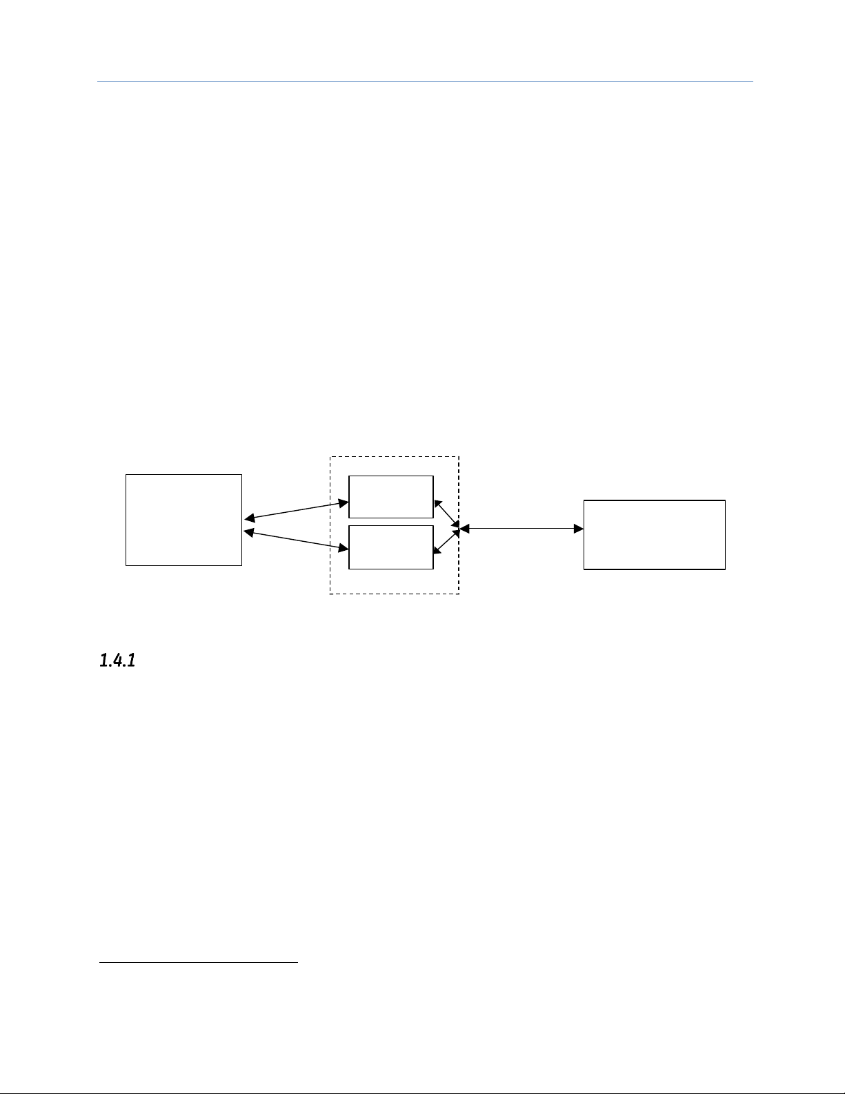
Chapter 1. Introduction
GFK-2224R June 2017 11
1.4 Ethernet Redundancy Operation
2
Note: Ethernet Redundancy Operation is not supported on the RX3i CPE305/CPE310 embedded
Ethernet Interface.
The Redundant IP feature of the Ethernet Interface allows a single IP address called the Redundant IP address to
be assigned to two Ethernet modules. The two modules are in two different PLCs that are configured as a
redundant system.
Note: The CPE400/CPE100 do not support Redundant IP at this time.
The Redundant IP Address is configured in addition to the normal unique (direct) IP address of each interface.
Only one of the two Ethernet interfaces that share the Redundant IP address may use the Redundant IP address
at any time; this is the “active” unit. When commanded by its PLC CPU, this Ethernet interface activates the
Redundant IP address and starts responding to the Redundant IP address in addition to its direct IP address. The
active unit continues responding to the Redundant IP address until it is commanded to deactivate the
Redundant IP or until the Ethernet interface determines that it has lost communications with the PLC CPU.
The other unit (the “backup” unit) does not initiate communications or respond on the network using the
Redundant IP address. It can only use the Redundant IP address if it is commanded by its CPU to become the
active unit.
Both the active and backup unit may continue to use their individual direct IP addresses, permitting programmer
connection to the active or backup PLC at any time.
PLC A
PLC B
Redundant System
Programmer
Remote host
(HMI, PLC, etc.)
Redundant
IP Address
Direct IP
Addresses
Figure 2: Ethernet Operation in Redundancy Mode
The Redundant IP feature is supported by Hot Standby (HSB) CPUs and non-HSB CPUs.
HSB CPU Redundancy
An HSB system uses redundancy CPUs that provide the coordination between the PLC units in the system and
determine which is the active unit and which is the backup unit. HSB redundancy requires dedicated links to
provide communications between the units in a redundancy system. Redundancy CPUs that include an
embedded Ethernet Interface have a “CRE” designation, for example IC698CRE040. For information about HSB
architectures, refer to the PACSystems Hot Standby CPU Redundancy User’s Guide, GFK-2308.
2
Not supported on the RX3i CPE305/CPE310 embedded Ethernet Interface.
Page 28
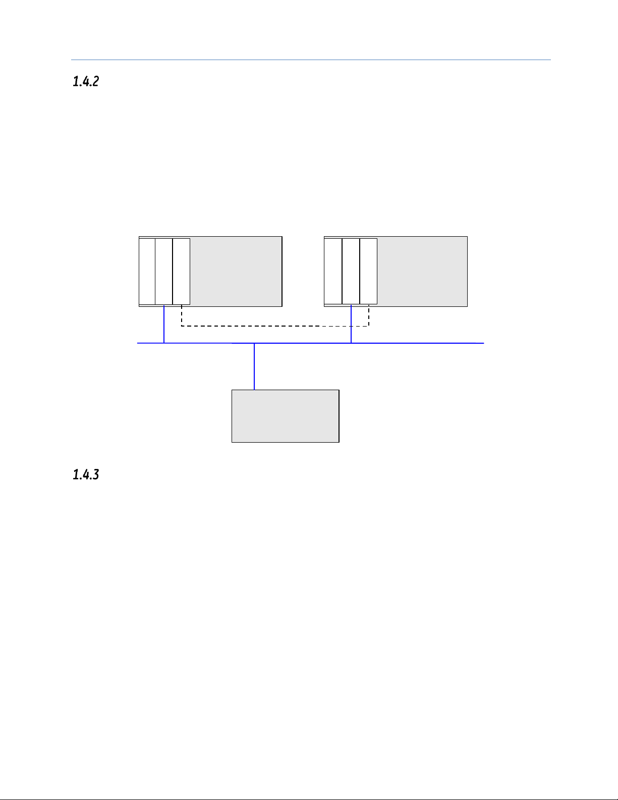
Chapter 1. Introduction
12 PACSystems* RX7i, RX3i and RSTi-EP TCP/IP Ethernet Communications User Manual GFK-2224R
Non-HSB Redundancy
Non-HSB redundancy systems use RX7i or RX3i CPUs that do not have specialized firmware for controlling
redundancy operations. (These CPUs have a “CPE” or “CPU” designation.) In these systems, the application logic
coordinates between CPUs that act as redundant partners, and determines which CPU is the active unit and
which are backup units. The figure below illustrates the use of the redundant IP feature in a non-HSB
redundancy system. Two non-HSB CPUs (designated primary and secondary) are linked by a communications
connection. An Ethernet interface in each controller is configured with Redundant IP enabled so that they share
a Redundant IP address. As in an HSB system, only the active Ethernet interface can communicate through the
Redundant IP address to produce EGD exchanges or to initiate Channel operations.
The application logic must monitor the status of the Ethernet modules in the system to manage the
active/backup status of each controller.
C
P
U
Primary Controller
C
P
U
Secondary Controller
Ethernet
E
T
M
E
T
M
Remote Device
L
I
N K L
I
N
K
Figure 3: Basic non-HSB System with Redundant IP
Effect of Redundancy Role Switching on Ethernet Communications
When a redundancy role-switch occurs, Ethernet communications switch to the backup unit, which has no
knowledge of any communication state at the previously-active unit. The application must include logic to
detect loss of communication during a redundancy role switch and to then reinitiate communication.
To remote hosts on the network, the redundant system is viewed as a single PLC with high reliability; the remote
host neither knows nor cares which PLC is the active unit. By using the Redundant IP address, the remote host
always communicates with the active unit. When a redundancy role switch occurs, the formerly-active PLC
gives up ownership of the Redundant IP address and takes down all connection-oriented communications
currently using the Redundant IP address. The applications in the redundant system and remote hosts must
reestablish any such communications; the new Redundant IP connections will use the newly active PLC.
The programmer can still communicate directly with each PLC in the redundant system (for example, to store
new logic or configuration) using the direct IP address of each Ethernet Interface.
Role Switching In HSB Redundancy Systems
In HSB redundancy systems, a role switch is initiated automatically by the redundancy CPU when the active unit
detects a fatal fault, is placed in Stop mode, or is powered off. An HSB role switch can also be initiated manually
or by the application logic. For additional information about role switches in HSB systems, refer to the
PACSystems Hot Standby CPU Redundancy User’s Guide, GFK-2308.
Page 29

Chapter 1. Introduction
GFK-2224R June 2017 13
Role Switching in Non-HSB Redundancy Systems
When redundant IP is enabled for an Ethernet module in a non-HSB CPU system, it is the responsibility of
application logic to set the redundancy mode of the Ethernet module. The Set Application Redundancy Mode
Service Request (SVC_REQ 55) instruction is used to inform the Ethernet module of the current redundancy role
of the host CPU. This SVC_REQ should be used to provide redundancy role switch notification to all Ethernet
interfaces in the controller that are configured for redundant IP operation.
After commanding a role switch for an Ethernet interface, the application logic can monitor the module’s LAN
Interface Status (LIS) block to determine when it has activated the Redundancy IP address. For details about the
LIS, refer to “Monitoring the Ethernet Interface Status Bits” in Chapter 12
Note: The application must allow sufficient time for Redundant IP activation (at least 120msec) before
commanding another redundancy role switch.
When an Ethernet interface recognizes that a redundant IP address has been configured for it, the module
sends a mail message to the CPU to register for redundancy role switch notification. In non-HSB systems, the
Ethernet interface is initially put into backup mode. After power up, the application logic must use a SVC_REQ to
set the redundancy state to the desired value. Once running, the CPU remembers the last commanded
redundancy role sent to that Ethernet interface. When an Ethernet interface is restarted, the CPU automatically
commands the Ethernet interface to its last redundancy state without explicit action by the application logic.
Going to Stop Mode
When a non-HSB CPU goes to Stop mode, Ethernet interfaces that are configured for redundant IP are
automatically set to backup mode. When the CPU is subsequently returned to Run mode, the Ethernet interfaces
remain in backup mode until the application logic sets the redundancy mode to active.
Stop/IO Scan Enabled Mode
In this mode, I/O scanning including EGD service continues when the non-HSB CPU is stopped. However,
Ethernet interfaces configured for redundant IP operation are automatically set to backup mode and normal
EGD production for those interfaces is stopped. Only the EGD exchanges with Produce in backup mode enabled
are produced while the CPU is in Stop/IO Scan Enabled mode. To stop production for all EGD produced
exchanges including Produce in backup mode exchanges, choose the Stop/IO Scan Disabled mode of operation.
Commanding a Role Switch in a Non-HSB Redundancy System
Use the Set Application Redundancy Mode service request (SVC_REQ 55) with non-HSB CPUs to request that the
CPU send redundancy role switch commands to all Ethernet interfaces in that PLC that are configured for
redundant IP operation. For details on using the Service Request function, refer to the PACSystems CPU
Reference Manual, GFK-2222.
This function has an input parameter block with a length of one word.
address
0=Backup redundancy role
1=Active redundancy role
SVC_REQ 55 is recognized in non-HSB CPUs only. This service request sends a role switch command to all
Ethernet interfaces in the PLC that are configured for redundant IP operation. The application must monitor the
LAN Interface Status (LIS) word for each Ethernet interface to determine whether the Redundant IP address is
active at that interface.
SVC_REQ 55 has no effect on Ethernet interfaces that are not configured for redundant IP operation.
SRTP Server Operation in a Redundancy System
Only the active unit maintains SRTP Server connections at the Redundant IP address and is able to respond to
SRTP requests. The backup unit does not respond to the Redundant IP address. When an Ethernet interface
changes from active to backup state, it takes down all SRTP Server connections and their underlying TCP
connections that use the Redundant IP address.
Both the active and backup units maintain SRTP Server connections at the direct IP address for network
communication with the programmer. Other remote hosts should use the Redundant IP address when
Page 30

Chapter 1. Introduction
14 PACSystems* RX7i, RX3i and RSTi-EP TCP/IP Ethernet Communications User Manual GFK-2224R
communicating to a redundant system. Existing SRTP Server connections at the direct IP address are not
disturbed when the Ethernet interface switches between active and backup states.
SRTP Client Operation in a Redundancy System
Only the active unit establishes and maintains SRTP Client connections (channels). The backup unit does not
initiate any SRTP Client operations. If SRTP Client operations are attempted, a COMMREQ error status is returned
to the local logic program. When the Ethernet interface changes from active to backup state, it takes down all
SRTP Client connections and their underlying TCP connections.
Because it can take some time to take down a TCP connection, the redundant system should reserve a spare
SRTP Client connection for each connection using the Redundant IP address. That will prevent temporary
resource problems when establishing new SRTP Client connections to the new active unit while the previous
connections to the old active unit are being taken down.
Modbus TCP Server Operation in a Redundancy System
Only the active unit maintains Modbus TCP Server connections at the Redundant IP address and is able to
respond to Modbus TCP requests. The backup unit does not respond to the Redundant IP address. When an
Ethernet interface changes from active to backup state, it takes down all Modbus TCP Server connections and
their underlying TCP connections that use the Redundant IP address.
Remote hosts should use the Redundant IP address when communicating to a redundant system. Existing
Modbus TCP Server connections at the direct IP address are not disturbed when the Ethernet interface switches
between active and backup states.
Modbus TCP Client Operation in a Redundancy System
Only the active unit establishes and maintains Modbus TCP Client connections (channels). The backup unit does
not initiate any Modbus TCP Client operations. If Modbus TCP Client operations are attempted, a COMMREQ error
status is returned to the local logic program. When the Ethernet interface changes from active to backup state,
it takes down all Modbus TCP Client connections and their underlying TCP connections.
Because it can take some time to take down a TCP connection, the redundant system should reserve a spare
Modbus TCP Client connection for each connection using the Redundant IP address. That will prevent temporary
resource problems when establishing new Modbus TCP Client connections to the new active unit while the
previous connections to the old active unit are being taken down.
EGD Class 1 (Production & Consumption) in a Redundancy System
The active unit produces Ethernet Global Data exchanges to the network. The backup unit produces only the
EGD exchanges for which Produce in Backup Mode is enabled. When the active Ethernet interfaces changes to
backup, it stops production of all EGD exchanges.
When configured for Redundant IP operation, the active and backup Ethernet interfaces should be configured to
consume EGD exchanges via multicast host groups or the local subnet broadcast address. This permits both the
active and backup units to receive the latest data from the network. Unicast operation is not recommended. The
backup unit does not consume any unicast exchanges at the Redundant IP address.
EGD Class 2 Commands in a Redundancy System
Remote hosts should use the Redundant IP address when communicating to a redundant system. Only the
active unit responds to EGD commands. The backup unit does not respond to the Redundant IP address. When
the active Ethernet interface changes to backup, any EGD command currently in process over the Redundant IP
address is ended.
When configured for Redundant IP operation, only the active unit sends EGD commands on the network. If the
backup unit tries to initiate any EGD commands, a COMMREQ error status is returned to its application program.
When the active Ethernet interfaces changes to backup, any EGD commands in process are ended.
Although not recommend, EGD commands may be issued to the direct IP address. Both the active and backup
units will respond to EGD commands received at the direct IP address.
Page 31

Chapter 1. Introduction
GFK-2224R June 2017 15
Web Server Operation in a Redundancy System
Only the active unit processes Web server requests at the Redundant IP address and responds to Web page
requests. The backup unit does not respond to the Redundant IP address. When the active Ethernet interface
changes to backup, it takes down all Web server connections and their underlying TCP connections. The Web
server maintains its underlying TCP connection only long enough to process each web page request; a new TCP
connection is opened, used, and closed for each subsequent Web page display or update. So unless a Web page
change or update is requested during the redundancy role switch, the operation of the Redundant IP address is
transparent to the Web remote browser. Any Web page request in process over the Redundant IP when a role
switch occurs is terminated.
Although not recommended, the remote browser may issue Web server requests to the direct IP address. Both
the active and backup units respond to Web server requests received at the direct IP address. Remote Web
browsers are expected to use the Redundant IP address when communicating to a redundant system.
FTP Operation in a Redundancy System
FTP operations are used to transfer setup and configuration data to the Ethernet interface, not for
communication with the actual PLC application. Therefore, FTP operations should only be performed using the
direct IP address.
SNTP Operation in a Redundancy System
A PACSystems Ethernet Interface can operate as an SNTP client only, so it only receives broadcast time
messages from an SNTP Server on the network. SNTP operation is unaffected by the current Ethernet
redundancy state or by redundancy role switches.
Remote Station Manager Operation in a Redundancy System
The remote Station Manager should respond to the direct IP address regardless of whether the unit is active or
backup, or whether or not Redundant IP is configured.
Only the active unit responds to remote Station Manager commands at the Redundant IP address. The backup
unit does not respond to the Redundant IP address. (Station Manager responses from the Redundant IP address
can be misleading because it is difficult to determine which Ethernet interface is actually responding.)
IP Address Configuration in a Redundancy System
Redundancy systems should explicitly configure both the direct IP address and the Redundant IP address. Do
not set up the direct IP address via BOOTP.
The Redundant IP address must be configured on the same local sub-network as the direct IP address and
gateway IP address (if used).
Page 32

GFK-2224R June 2017 16
Chapter 2 Installation and Start-up: RX3i/RSTi-EP
Embedded Interface
The RX3i CPUs with CPExxx designation (CPE305, CPE310, CPE330 and CPE400) and RSTi-EP CPU CPE100
provide an embedded Ethernet interface for programmer communications. This chapter describes user
features and provides basic installation and startup procedures for this interface.
▪ Ethernet Interface Controls and Indicators
▪ Module Installation
▪ Connection to a 10Base T/100Base Tx Network (all CPExxx) or to a 1000Base T (CPE330 and CPE400
only)
▪ Pinging TCP/IP Ethernet Interfaces on the Network
Note: CPE330 Release 8.60 provides support for EGD Class 1. PME 8.60 SIM5 is required to
support EGD on both LAN1 and LAN2. All CPE400/CPE100 releases support this feature.
Note: Effective with RX3i CPE310/CPE305 Firmware Release 8.30, the CPU itself also supports
EGD3 Class 1. Prior to that firmware release, EGD was only available in the RX3i via the
RX3i Ethernet Interface module (ETM001).
Note: For features, installation and startup of the RX3i rack-based Ethernet module (ETM001),
see Chapter 3.
2.1 RX3i/RSTi-EP Embedded Ethernet Interface Indicators
The Ethernet port has two LED indicators, 100 and LINK. The 100 LED indicates the network data speed (10 or
100 Mb/sec). This LED is lit if the network connection at that network port is 100 Mbps.
The LINK LED indicates the network link status and activity. This LED is lit when the link is physically connected.
It blinks when traffic is detected at that network port.
Ethernet Port LEDs Operation
CPE305/CPE310 Ethernet LED Operation
LED
LED State
On
Blinking
Off
Ethernet Port State
100
On, Green
Network data speed is 100 Mbps.
Off
Network data speed is 10 Mbps.
LINK
On, Amber
The link is physically connected.
Blinking, Amber
Traffic is detected at the port.
Off
The Ethernet port is not physically connected.
3
Proficy Machine Edition Release 8.50 SIM 7 is required for EGD on Embedded Ethernet interface of
CPE305/CPE310.
Page 33

Chapter 2. Installation and Start-up: RX3i/RSTi-EP Embedded Interface
GFK-2224R June 2017 17
CPE330 Ethernet LED Operation
LED
LED State
Operating State
LINK (upper)
On Green
The corresponding link is physically connected.
Blinking
Green
Traffic is detected at the corresponding port.
Off
No connection detected at corresponding port.
1Gbps
(lower)
On Amber
(LAN1) or
Corresponding network data speed is 1 Gbps.
On Green
(LAN2)
Off
Corresponding network data speed is 100 Mbps or 10 Mbps.
CPE400 Ethernet LED Operation (LAN1, LAN2, LAN3)
LED
LED State
Operating State
Link
Status
(upper)
On Green
The corresponding link has been established.
Blinking
Green
Traffic is detected at the corresponding port.
Off
No connection established at corresponding port.
Link
Speed
(lower)
On Green
Corresponding data speed is 1 Gbps or 100 Mbps.
Off
Corresponding network data speed is 10 Mbps
CPE100 Ethernet LED Operation (LAN1, LAN2)
LED
LED State
Operating State
Link
Speed
(upper)
On Amber
Corresponding data speed is 100 Mbps.
Off
Corresponding network data speed is 10 Mbps
Link
Status
(lower)
On Green
The corresponding link has been established.
Blinking
Green
Traffic is detected at the corresponding port.
Off
No connection established at corresponding port.
Module Installation
For general information about CPU module and system installation refer to the PACSystems RX3i System
Manual, GFK-2314 Chapters 2 & 3. For RSTi-EP CPU model refer RSTi-EP System Manual, GFK-2958D.
Page 34

Chapter 2. Installation and Start-up: RX3i/RSTi-EP Embedded Interface
18 PACSystems* RX7i, RX3i and RSTi-EP TCP/IP Ethernet Communications User Manual GFK-2224R
2.2 Ethernet Port Connector
The RX3i CPE305 and CPE310 CPUs provide a 10BaseT/100BaseTX
Ethernet network port connector.
Figure 4: RJ-45 Connector
Note: Although the CPE310 can be configured as a CPU310 for backward compatibility, an
Ethernet cable should not be connected to the device when it is configured as a CPU310.
Ethernet is not supported when CPE310 is configured as a CPU310 and the Ethernet port
should not be connected to any network as it may have adverse effects on the network
and/or operation of the CPU.
Note: When a CPE330 is configured as a CPU320, Ethernet properties cannot be configured.
However, the embedded Ethernet ports may be used with the default IP Addresses.
Connection to a 10Base-T / 100Base Tx Network
Either shielded or unshielded twisted pair cable may be attached to a port. The 10Base-T/100Base Tx twisted
pair cable must meet the applicable IEEE 802 standards. Category 5 cable is required for 100BaseTX operation.
The Ethernet port automatically senses the speed (10Mbps or 100Mbps), duplex mode (half-duplex or fullduplex) and cable configuration (straight-through or crossover) attached to it with no intervention required.
10Base-T/100Base Tx Port Pinouts
Pin Number4
Signal
Description
1
TD+
Transmit Data +
2
TD–
Transmit Data –
3
RD+
Receive Data +
4
NC
No connection
5
NC
No connection
6
RD–
Receive Data –
7
NC
No connection
8
NC
No connection
Note: Pin assignments are provided for troubleshooting purposes only. 10Base-T/100Base-Tx
cables are readily available from commercial distributors. We recommend purchasing
rather than making 10Base-T/100Base-Tx cables.
4
Pin 1 is at the bottom right of the Station Manager port connector as viewed from the front of the module.
ETHERNET
Page 35

Chapter 2. Installation and Start-up: RX3i/RSTi-EP Embedded Interface
GFK-2224R June 2017 19
The programmer is connected to the Ethernet Interface through a 10Base-T or 100Base-Tx network.
10BaseT/100Base Tx Twisted Pair Cable
Hub/Switch/Repeater
To other network devices
Ethernet Port
on RX3i/RSTi-EP
CPExxx
Programmer
Figure 5: Ethernet Cable Routing
2.3 Pinging TCP/IP Ethernet Interfaces on the Network
PING (Packet InterNet Grouper) is the name of a program used on TCP/IP networks to test reachability of
destinations by sending them an ICMP echo request message and waiting for a reply. Most nodes on TCP/IP
networks, including the PACSystems Ethernet Interface, implement a PING command.
You should ping each installed Ethernet Interface. When the Ethernet Interface responds to the ping, it verifies
that the interface is operational and configured properly. Specifically it verifies that acceptable TCP/IP
configuration information has been downloaded to the Interface.
For configuration details, including setting an initial IP address, refer to Chapter 4.
Pinging the Ethernet Interface from a UNIX Host or Computer
Running TCP/IP Software
A ping command can be executed from a UNIX host or computer running TCP/IP (most TCP/IP communications
software provides a ping command) or from another Ethernet Interface. When using a computer or UNIX host,
you can refer to the documentation for the ping command, but in general all that is required is the IP address of
the remote host as a parameter to the ping command. For example, at the command prompt type:
ping 10.0.0.1
Determining if an IP Address is Already Being Used
Note: This method does not guarantee that an IP address is not duplicated. It will not detect a device that is
configured with the same IP address if it is temporarily off the network.
It is very important not to duplicate IP addresses. To determine if another node on the network is using the same
IP address:
1. Disconnect your Ethernet Interface from the LAN.
2. Ping the disconnected Interface’s IP address. If you get an answer to the ping, the chosen IP address is
already in use by another node. You must correct this situation by assigning a unique IP addresses.
Page 36

Chapter 3. Installation and Start-up: Rack-based and RX7i Embedded Interface
20 PACSystems* RX7i, RX3i and RSTi-EP TCP/IP Ethernet Communications User Manual GFK-2224R
Chapter 3 Installation and Start-up: Rack-based and RX7i
Embedded Interface
This chapter describes the Ethernet Interface’s user features and basic installation procedures.
▪ Ethernet Interface Controls and Indicators
- Ethernet LEDs
- Ethernet Restart Pushbutton
▪ Module Installation
- RX7i CPU with Embedded Ethernet Interface
- Rack-based Ethernet Interface Modules
▪ Ethernet Port Connectors
- Embedded Switch
- Connection to a 10Base T / 100Base Tx Network
▪ Station Manager Port
▪ Verifying Proper Power-Up of the Ethernet Interface After Configuration
▪ Pinging TCP/IP Ethernet Interfaces on the Network
Features of the embedded RX7i CPU Ethernet Interface and the rack-based RX3i/RX7i Ethernet interfaces are
the same unless noted otherwise.
Note: For features, installation and startup of the RX3i embedded Ethernet interface, see
Chapter 2.
Page 37

Chapter 3. Installation and Start-up: Rack-based and RX7i Embedded Interface
GFK-2224R June 2017 21
3.1 Ethernet Interface Controls and Indicators
Features of the RX7i embedded CPU Ethernet Interface and the RX7i and RX3i rack-based
Ethernet Interface modules are the same unless noted otherwise.
The Ethernet Interface provides:
1. Seven light emitting diode (LED) indicators
▪ Ethernet Module OK (EOK)
▪ LAN Online (LAN)
▪ Status (STAT)
▪ Two Ethernet network activity LEDS (LINK)
▪ Two Ethernet network speed LEDS (100)
2. Ethernet Restart Pushbutton
3. Two 10BaseT/100BaseTX Ethernet network port connectors. There is only one interface
to the network (only one Ethernet address and only one IP address).
4. Station Manager (RS-232) serial port
ETHERNET
RESTART
EOK
LAN
STAT
10/100 ENET A2
100
LINK
StaMgr
10/100 ENET A1
100
LINK
Figure 6: RX7i
Faceplate
Ethernet LEDs
The LEDs indicate the state and status of the Ethernet Interface. The LEDs indicate the state and status of the
Ethernet Interface.
1. For the Switched Ports
a) For each connector, the bottom LED is the LINK SPEED LED. This will be on for 1000Mbps; off for all
other speeds.
Note: The ETM/CPE305/CPE310 only supports two speeds so for it, it is ON when 100Mbps and
off when 10Mbps – CPE330 supports 3 speeds.
b) For each connector, the top LED is the LINK/ACTIVITY LED. This will be ON when there is link at any
speed; and BLINKING when there is traffic in either direction.
2. For the Unswitched Port
a) The bottom LED (orange) is the LINK SPEED. This will be on for 1000Mbps; off for all other speeds.
NOTE: The ETM/CPE305/CPE310 only supports two speeds so for it, it is ON when 100Mbps and
off when 10Mbps – CPE330 and CPE400 both support three speeds.
b) The top LED is the LINK/ACTIVITY LED. This will be ON when there is link at any speed; and
BLINKING when there is traffic in either direction.
Page 38

Chapter 3. Installation and Start-up: Rack-based and RX7i Embedded Interface
22 PACSystems* RX7i, RX3i and RSTi-EP TCP/IP Ethernet Communications User Manual GFK-2224R
RX7i Embedded
and Rack-Based
RX3i Rack-
Based
LED State
On
Blinking
Off
Indicates
EOK
LAN
STAT
ETHERNET OK
LAN OK
LOG EMPTY
Fast Blink
Off
Off
Performing Diagnostics
EOK
LAN
STAT
ETHERNET OK
LAN OK
LOG EMPTY
Slow Blink
Off
Off
Waiting for Ethernet
configuration from CPU
EOK
LAN
STAT
ETHERNET OK
LAN OK
LOG EMPTY
Slow Blink5
On/Traffic/Off
Slow Blink5
Waiting for IP Address
EOK
LAN
STAT
ETHERNET OK
LAN OK
LOG EMPTY
On
On/Traffic/Off
On/Off
Operational
EOK
LAN
STAT
ETHERNET OK
LAN OK
LOG EMPTY
Blink error code
Off
Off
Hardware failure. See
Chapter 12 for blink
code definitions.
EOK
LAN
STAT
ETHERNET OK
LAN OK
LOG EMPTY
Slow Blink6
Slow Blink6
Slow Blink6
Firmware Update
LAN LED Operation
The LAN LED (LAN OK on the RX3i Ethernet module) indicates access to the Ethernet network. During normal
operation and while waiting for an IP address, the LAN LED blinks when data is being sent or received over the
network directed to or from the Ethernet interface. It remains on when the Ethernet interface is not actively
accessing the network but the Ethernet physical interface is available and one or both of the Ethernet ports is
operational.
It is off otherwise unless firmware update is occurring.
STAT LED Operation
The STAT LED (LOG EMPTY on the RX3i Ethernet module) indicates the condition of the Ethernet interface in
normal operational mode. If the STAT LED is off, an event has been entered into the exception log and is
available for viewing via the Station Manager interface. The STAT LED is on during normal operation when no
events are logged.
In the other states, the STAT LED is either off or blinking and helps define the operational state of the module.
EOK LED Operation
The EOK LED (ETHERNET OK on the RX3i Ethernet module) indicates whether the module is able to perform
normal operation. This LED is on for normal operation and flashing for all other operations. When a hardware
5
EOK and STAT blink in unison.
6
All LEDs blink in unison; pattern same for awaiting or performing load.
Page 39

Chapter 3. Installation and Start-up: Rack-based and RX7i Embedded Interface
GFK-2224R June 2017 23
or unrecoverable runtime failure occurs, the EOK LED blinks a two-digit error code identifying the failure. For a
list of blink codes and their meanings, see Chapter 12.
Ethernet Port LEDs Operation (100Mb and Link/Activity)
Each of the two Ethernet ports (Ports 1A and 1B) has two LED indicators, 100 and LINK. The 100 LED indicates
the network data speed (10 or 100 Mb/sec). This LED is lit if the network connection at that network port is 100
Mbps.
The LINK LED indicates the network link status and activity. This LED is lit when the link is physically connected.
It blinks when traffic is detected at that network port. Traffic at the port does not necessarily mean that traffic
is present at the Ethernet interface, since the traffic may be going between ports of the switch.
Ethernet Restart Pushbutton
The Ethernet Restart pushbutton is used to manually restart the Ethernet firmware without power cycling the
entire system. It is recessed to prevent accidental operation.
Restart Pushbutton Operation for Version 3.6 and Later
For PACSystems Ethernet interfaces version 3.6 and later, an Ethernet restart occurs when the Restart
pushbutton is released. The duration that the Restart pushbutton is pressed determines the operation after the
restart occurs. In all cases, the EOK, LAN and STAT LEDs briefly turn on in unison as an LED test. The Ethernet
port LEDs are not affected by a manual restart of the Ethernet firmware.
To restart the Ethernet interface normally, press the Ethernet Restart pushbutton for less than 5 seconds.
If the Ethernet interface uses any optional Ethernet plug-in applications, these applications are ordinarily
started upon each power-up or restart. To restart the Ethernet interface without starting any Ethernet plug-in
applications, press and hold the Ethernet Restart pushbutton between 5 and 10 seconds.
To restart the Ethernet interface into firmware update operation, press and hold the Ethernet Restart
pushbutton for more than 10 seconds. This is typically done during troubleshooting to bypass possibly invalid
firmware and allow valid firmware to be loaded using WinLoader.
Pushbutton-controlled restart operations are listed below, with the LED indications for each.
Restart Operation
Depress Ethernet Restart
pushbutton for
Ethernet LEDs
Illuminated
Restart the Ethernet interface normally, and start any
optional Ethernet plug-in applications that are being
used.
Less than 5 seconds
EOK, LAN, STAT
Restart the Ethernet interface without starting any
Ethernet plug-in applications.
5 to 10 seconds
LAN, STAT
Restart the Ethernet interface into firmware update
operation.
More than 10 seconds
STAT
When forced into firmware update operation, but before the firmware update actually begins, pressing the
Ethernet Restart pushbutton again exits the firmware update mode and restarts with the existing firmware.
Once the firmware update actually begins, the existing firmware is erased and the Ethernet Restart pushbutton
is disabled until the firmware update is complete.
Restart Pushbutton Operation Prior to Version 3.6
For PACSystems Ethernet interfaces earlier than version 3.6, pressing the Ethernet Restart pushbutton restarts
the module immediately. The EOK, LAN and STAT LEDs briefly turn on in unison as an LED test. These three LEDs
are turned on for ½ second and are then turned off when the firmware is restarted. The Ethernet port LEDs are
not affected by a manual restart of the Ethernet firmware.
Page 40

Chapter 3. Installation and Start-up: Rack-based and RX7i Embedded Interface
24 PACSystems* RX7i, RX3i and RSTi-EP TCP/IP Ethernet Communications User Manual GFK-2224R
3.2 Module Installation
For general information about module and system installation, or if the installation requires CE Mark
compliance, refer to the PACSystems RX7i Hardware Installation Manual, GFK-2223 or the PACSystems RX3i
System Manual, GFK-2314.
Installing an RX7i CPU with Embedded Ethernet Interface
Warning
Do not insert or remove the CPU module with power applied. This could cause
the CPU to stop, damage the module, or result in personal injury.
1. Record the 12-digit hexadecimal MAC Address from the printed label located on the rear wall of CPU
battery compartment. The label is visible when the battery is removed from its compartment. (The battery
does not need to be disconnected to temporarily remove it from the compartment.) For compatible
batteries and battery installation procedures for specific CPUs, refer to the PACSystems RX3i and RX7i
Controllers Battery Manual, GFK-2741.
2. Install the CPU in the rack. Refer to PACSystems RX7i Hardware Installation Manual, GFK-2223 for
installation instructions.
3. Set the PLC to Stop mode via the Run/Stop switch or the programming software.
Installing an RX7i Ethernet Interface Module
1. Record the 12-digit hexadecimal MAC Address from the printed
label on the Ethernet Interface. The label is visible only with
module out of the rack.
2. Be sure the rack power is OFF.
3. Slide the module into the slot for which it was configured in the
system. (Must go into main rack.)
4. Press the module firmly in place, but do not force the module.
Tighten the screws on the top and bottom tabs.
5. Connect one or both of the network ports on the Ethernet
Interface to the Ethernet network.
6. Turn on power to the PACSystems rack.
7. Set the PLC to Stop mode via the Run/Stop switch or the
programming software.
MAC Address Label
Figure 7: MAC Address on RX7i
Page 41

Chapter 3. Installation and Start-up: Rack-based and RX7i Embedded Interface
GFK-2224R June 2017 25
Installing an RX3i Ethernet Interface Module
1. Record the 12-digit hexadecimal MAC Address from the printed label
located on the front of the Ethernet Module.
2. PLC rack power may be off or on (“hot insertion”). For hot insertion, be
sure that all cables are disconnected from the Ethernet module
3. Slide the module into the slot for which it was configured in the system.
(Must go into main rack.)
4. Press the module firmly in place, but do not force.
5. Connect one or both of the network ports on the Ethernet Interface to the
Ethernet network.
6. Unless this is a hot insertion, turn on power to the PACSystems rack.
Set the PLC to Stop mode via the Run/Stop switch or the programming
software
Figure 8: MAC Address on RX3i
ETM001 Module
Page 42

Chapter 3. Installation and Start-up: Rack-based and RX7i Embedded Interface
26 PACSystems* RX7i, RX3i and RSTi-EP TCP/IP Ethernet Communications User Manual GFK-2224R
3.3 Ethernet Port Connectors
The Ethernet Interface has two Ethernet port connectors, each of which supports both 10Base-T and 100BaseTx operation using either full-duplex or half-duplex operation. These 8-pin RJ-45 connectors are used to
connect the Ethernet Interface to a hub, repeater, switch, or other Ethernet device.
Embedded Switch
The two Ethernet port connectors are controlled by an embedded network switch in the module. The module
has only one interface to the network (one Ethernet address and one IP address).
PACSystems
Ethernet Interface
Ethernet
Processor
Ethernet
MAC
10/100 Network
Switch
Port 1A
Port 1B
Figure 9: Diagram of Embedded Ethernet Switch
For simple installations, the embedded switch allows devices to be connected without additional components.
Operator
Interface
PLC
PLC
Personal
Computer
Figure 10: System Diagram: Ethernet Routing Using Embedded Switch
It is possible to daisy-chain PLCs together without additional components, but that should be done with great
care. Power loss or reset at an Ethernet interface causes loss of communication to any devices downstream
from that Ethernet interface in the daisy chain. Restarting the Ethernet interface (via the Ethernet Restart
pushbutton, for example) disrupts daisy chain communication.
Page 43

Chapter 3. Installation and Start-up: Rack-based and RX7i Embedded Interface
GFK-2224R June 2017 27
Each switch port auto-negotiates (by default) to the correct link speed and duplex mode for the device
connected to the other end of the link. Each port operates independently, so devices at two different speeds
and/or duplex modes may be attached to the two ports. Each port also automatically detects the attached
cable and will work properly with either straight-through or crossover cables (by default).
Caution
The two Ethernet ports on the Ethernet Interface must not be connected,
directly or indirectly, to the same device. The connections in an Ethernet
network based on twisted pair cabling must form a tree and not a ring,
otherwise duplication of packets and network overload may occur.
Caution
The IEEE 802.3 standard strongly discourages the manual configuration of
duplex mode for a port (as would be possible using Advanced User Parameters).
Before manually configuring duplex mode for an Ethernet Interface port using
advanced user parameters (AUP), be sure that you know the characteristics of
the link partner and are aware of the consequences of your selection. Setting
both the speed and duplex AUPs on an IC698 Ethernet Interface port will disable
the port’s auto-negotiation function. If its link partner is not similarly manually
configured, this can result in the link partner concluding an incorrect duplex
mode. In the words of the IEEE standard: “Connecting incompatible DTE/MAU
combinations such as full duplex mode DTE to a half-duplex mode MAU, or a fullduplex station (DTE or MAU) to a repeater or other half-duplex network, can lead
to severe network performance degradation, increased collisions, late collisions,
CRC errors, and undetected data corruption.”
Note: If both speed and duplex mode of an Ethernet interface port are forced using the Advanced User
Parameters file, that port will no longer perform automatic cable detection. This means that if you
have the Ethernet interface port connected to an external switch or hub port you must use a crossover
cable. If you have the Ethernet interface port connected to the uplink port on an external switch or
hub, or if you have the Ethernet interface port directly connected to another Ethernet device, you must
use a normal cable.
Connection to a 10Base-T / 100Base Tx Network
Either shielded or unshielded twisted pair cable may be attached to a port. The 10Base-T/100Base Tx twisted
pair cables must meet the applicable IEEE 802 standards. Category 5 cable is required for 100BaseTX
operation.
Each Ethernet port automatically senses whether it is connected to a 10BaseT or 100BaseTX network, halfduplex or full-duplex. (The automatic negotiation of speed and/or duplex mode can be explicitly overridden
using Advanced User Parameter settings).
Page 44

Chapter 3. Installation and Start-up: Rack-based and RX7i Embedded Interface
28 PACSystems* RX7i, RX3i and RSTi-EP TCP/IP Ethernet Communications User Manual GFK-2224R
10Base-T/100Base Tx Port Pinouts
Pin Number4
Signal
Description
1
TD+
Transmit Data +
2
TD–
Transmit Data –
3
RD+
Receive Data +
4
NC
No connection
5
NC
No connection
6
RD–
Receive Data –
7
NC
No connection
8
NC
No connection
Note: Pin assignments are provided for troubleshooting purposes only. 10Base-T/100Base-Tx
cables are readily available from commercial distributors. We recommend purchasing
rather than making 10Base-T/100Base-Tx cables.
Connection Using a Hub/Switch/Repeater
Connection of the Ethernet Interface to a 10Base-T or 100Base-Tx network is shown below.
10BaseT/100Base Tx
Twisted Pair Cable
Hub/Switch/Repeater
To Other Network
Devices
Ethernet
Interface
10/100
10/100
Figure 11: Connection Using Hub/Switch/Repeater
Note: Care must be taken with the use of active network control devices, such as managed
switches. If a device inserts excessive latency, especially in regards to the ARP protocol,
produced EGD exchanges may generate PLC Fault Table entries indicating the loss of a
consumer when the PLC transitions from STOP to RUN. EGD data will be successfully
transferred after an initial delay.
Page 45

Chapter 3. Installation and Start-up: Rack-based and RX7i Embedded Interface
GFK-2224R June 2017 29
Direct Connection to the PACSystems Ethernet Interface
Connection of Ethernet devices directly to the Ethernet Interface is shown below:
10/100
10/100
10BaseT/100Base Tx
Twisted Pair Cable
Other Ethernet
devices such as PCs,
Ethernet Interfaces
on other PLCs,
Operator Interfaces
Ethernet
Interface
Figure 12: Direct Connection to the Embedded Ethernet Ports
3.4 Station Manager Port
The RX7i and rack-based RX3i Ethernet interfaces provide a dedicated RS-232 serial port for local Station
Manager use. This nine-pin D connector accepts a standard straight-through nine-pin RS-232 serial cable to
connect to a standard AT-style RS-232 port.
The following cable is available:
IC200CBL001 Cable, CPU Programming
Port Settings
The serial (COM) port of the terminal or computer that is connected to the Ethernet Interface must use the
same communications parameters as the Ethernet Interface.
The default values for the Station Manager port are 9600 bps, 8 bits, no parity, and 1 stop bit. If the Ethernet
Interface is configured with default values for this port, or the Ethernet Interface has not been configured, use
these default values. If the Ethernet Interface is configured with non-default values for this port, use those
values for the serial port settings of the terminal or computer.
Page 46

Chapter 3. Installation and Start-up: Rack-based and RX7i Embedded Interface
30 PACSystems* RX7i, RX3i and RSTi-EP TCP/IP Ethernet Communications User Manual GFK-2224R
Station Manager (RS-232) Port Pin Assignment
Pin No4
Signal
Direction
Description
1
DCD
IN
Data Carrier Detect
2
TX
OUT
Transmit Data
3
RX
IN
Receive Data
4
DSR
IN
Data Set Ready
5
GND
Signal Ground
6
DTR
OUT
Data Terminal Ready
7
CTS
IN
Clear to Send
8
RTS
OUT
Ready to Send
9
RI
IN
Ring Indicator
3.5 Verifying Proper Power-Up of the Ethernet Interface after
Configuration
After configuring the interface as described in Chapter 4, turn power OFF to the CPU for 3–5 seconds, then turn
the power back ON. This starts a series of diagnostic tests. The EOK LED will blink indicating the progress of
power-up.
The Ethernet LEDs will have the following pattern upon successful power-up. At this time the Ethernet Interface
is fully operational and on-line.
LED
Ethernet Interface Online
EOK
On
LAN
On, Off, or blinking, depending on network activity
STAT
On
If a problem is detected during power-up, the Ethernet Interface may not transition directly to the operational
state. If the Interface does not transition to operational, refer to “Diagnostics,” Chapter 12 for corrective action.
3.6 Pinging TCP/IP Ethernet Interfaces on the Network
PING (Packet InterNet Grouper) is the name of a program used on TCP/IP networks to test reachability of
destinations by sending them an ICMP echo request message and waiting for a reply. Most nodes on TCP/IP
networks, including the PACSystems Ethernet Interface, implement a PING command.
You should ping each installed Ethernet Interface. When the Ethernet Interface responds to the ping, it verifies
that the interface is operational and configured properly. Specifically, it verifies that acceptable TCP/IP
configuration information has been downloaded to the Interface.
For configuration details, including setting an initial IP address, refer to Chapter 4.
Pinging the Ethernet Interface from a UNIX Host or Computer
Running TCP/IP Software
A ping command can be executed from a UNIX host or computer running TCP/IP (most TCP/IP communications
software provides a ping command) or from another Ethernet Interface. When using a computer or UNIX host,
you can refer to the documentation for the ping command, but in general all that is required is the IP address of
the remote host as a parameter to the ping command. For example, at the command prompt type:
ping 10.0.0.1
Page 47

Chapter 3. Installation and Start-up: Rack-based and RX7i Embedded Interface
GFK-2224R June 2017 31
Determining if an IP Address is Already Being Used
Note: This method does not guarantee that an IP address is not duplicated. It will not detect a
device that is configured with the same IP address if it is temporarily off the network.
It is very important not to duplicate IP addresses. To determine if another node on the network is using the same
IP address:
1. Disconnect your Ethernet Interface from the LAN.
2. Ping the disconnected Interface’s IP address. If you get an answer to the ping, the chosen IP address is
already in use by another node. You must correct this situation by assigning unique IP addresses.
3.7 Ethernet Plug-in Applications
Ethernet interface versions 3.6 and later support the use of additional firmware images called Ethernet plug-in
applications, which may implement additional communication protocols. Up to three Ethernet plug-in
applications can be loaded into the Ethernet interface along with the Ethernet firmware via the WinLoader
utility. Each plug-in application is identified by a number (1-3). Once loaded, each Ethernet plug-in application
is stored in non-volatile memory where it is preserved until it is overwritten by WinLoading another Ethernet
plug-in application with the same number, or it is explicitly deleted via the pluginapp Station Manager
command (see TCP/IP Ethernet Communications for PACSystems Station Manager Manual, GFK-2225).
All Ethernet plug-in applications are started during normal Ethernet power-up or restart. During
troubleshooting, the Ethernet Restart pushbutton may be used to startup the Ethernet interface without the
plug-in applications (see “Ethernet Restart Pushbutton”).
The functional operation, PLC interfaces, and Station Manager support for each Ethernet plug-in application
are supplied separately from this user manual.
Page 48

Page 49

GFK-2224R June 2017 33
Chapter 4 Configuration
Before you can use the Ethernet Interface, you must configure it using Machine Edition Logic Developer-PLC
software.
This chapter includes configuration information for:
RX3i/RSTi-EP Embedded Ethernet Interface
Rack-based and RX7i Embedded Ethernet Interfaces
4.1 RX3i/RSTi-EP Embedded Ethernet Interfaces
Ethernet Configuration Data
The PACSystems PLC is configured exclusively by the Machine Edition Logic Developer-PLC programmer. For
initial programmer connection, an initial IP address must be manually assigned to the Ethernet interface as
described in this chapter. The PACSystems PLC does not support auto-configuration.
Generating / Storing / Loading the Configuration
The RX3i/RSTi-EP embedded Ethernet interface is configured as a sub-module of the CPE CPU module. The
RX3i/RSTi-EP embedded Ethernet Interface uses Ethernet Configuration and optional Advanced User Parameter
(AUP) Configuration. Both are generated at the Programmer, stored from the Programmer to the PLC as part of
the hardware configuration Store sequence, and may be loaded from the PLC to the Programmer as port of the
Configuration Load sequence. The optional AUP file must be manually generated with a text editor and then
imported into the Programmer. (See Appendix A for details.) Once stored to the PLC, the CPU maintains the
Ethernet configuration data in non-volatile memory over power cycles.
Neither CPE330, CPE400, nor CPE100 supports an AUP file. The configurable AUP parameters for these CPUs are
part of the configuration for the embedded Ethernet interface. For CPE330 and CPE400, this configuration
interface is available in PME 8.60 SIM5 or later. For CPE100, this configuration interface is available in PME 9.50
SIM2 or later.
Backup Configuration Data
The RX3i/RSTi-EP embedded Ethernet interface maintains a backup copy of the most recent Ethernet
configuration and AUP configuration in non-volatile memory. A PLC Configuration Clear does not affect this
backup Ethernet configuration data. When the configuration was not stored from the programmer, or the PLC
configuration has been cleared, the Ethernet interface uses its backup configuration.
Locally Edited Configuration Data
The embedded Ethernet configuration and AUP configuration cannot be locally edited via Station Manager. All
configuration changes must be performed via the programmer.
Page 50

Chapter 4. Configuration
34 PACSystems* RX7i, RX3i and RSTi-EP TCP/IP Ethernet Communications User Manual GFK-2224R
Initial IP Address Assignment
The RX3i/RSTi-EP embedded Ethernet Interface comes from the factory with a default IP default IP address
(192.168.0.100). This address is intended only for initial connection in order to complete the configuration and
must be changed before connecting to the Ethernet network. The IP address must be selected for proper
operation with your network and application; see your network administrator for the proper IP address value.
1. Using Proficy Machine Edition software, configure the CPE3xx CPU in an RX3i target (or) configure the
CPE100 in an RSTi-EP target and assign a new IP address to the embedded Ethernet interface:
To configure the embedded Ethernet interface, expand the CPU slot to
display the Ethernet interface.
Figure 13: Expand CPU Slot to
Display Ethernet Node
2. Right click the Ethernet interface to display its parameters: IP Address, Subnet Mask and Gateway IP
Address. Consult your network administrator for the proper values for these parameters.
Note: CPE100, CPE305 and CPE310 do not support the alternate methods of setting a
temporary IP address: the Set Temporary IP Address tool in PME, BOOTP or the Station
Manager CHSOSW command. CPE330 does support the Set Temporary IP Address tool in
PME but not the Station Manager CHSOSW command. Since the IP Addresses of the
CPE400 may be displayed on its OLED display, there is no need to support the Set
Temporary IP Address tool. To restore the default IP Address of the CPE100, please refer to
section 4.1.3, “Configuring the Ethernet Interface Parameters,” of this document or the
Operational Notes section of the CPE100 IPI, GFK-3013.
3. Go online with the target and download the configuration. You can use one of the following methods for
the initial connection to the CPE3xx:
▪ Through the embedded Ethernet port, using the factory-loaded default IP address (192.168.0.100). To
set the IP address that PME will use to connect to the RX3i, open the target properties, set Physical Port
to ETHERNET, and then enter the factory default IP address value.
Note: The factory-loaded default IP address is valid only when hardware configuration has
never been stored to the Controller. This value is overwritten with the configured IP
address each time that hardware configuration is stored to the Controller.
▪ Through the Ethernet connection of an ETM001 in the same rack with a known IP address
configuration.
▪ Through the RS-232 COM1 serial port – This is a DCE (data communications equipment) port that
allows a simple straight-through cable to connect with a standard nine-pin AT-style RS-232 port.
▪ CPE310: Through the RS-485 COM2 serial port – Use SNP programming cable IC690ACC901
Page 51

Chapter 4. Configuration
GFK-2224R June 2017 35
Configuring the Ethernet Interface Parameters
First, establish communications between the computer hosting PME and the CPU. Consider the following
methods:
Default IP Addresses for
CPE305/CPE310/CPE330/CPE400
Embedded Ethernet
Initial Ethernet communication with the CPU may be established using
the default IP addresses programmed at the factory:
Note that the IP subnet 192.168.180.x is reserved on the CPE400. It is
not available for configuration on any of the CPU’s Ethernet ports.
CPE305/CPE310 and
CPE330/CPE400 LAN1
CPE330/CPE400 LAN2
CPE400
LAN37
IP
Address:
192.168.0.100
10.10.0.100
0.0.0.0
Subnet
Mask:
255.255.255.0
255.255.255.0
0.0.0.0
Gateway:
0.0.0.0
0.0.0.0
0.0.0.0
Default IP Addresses for RSTi-EP
CPE100 Embedded Ethernet
Initial Ethernet communication with the CPU may be established using
the default IP addresses programmed at the factory:
Note that the IP subnet 192.168.180.x is reserved on the CPE100. It is
not available for configuration on any of the CPU’s Ethernet ports.
CPE100 LAN1
CPE100 LAN2
IP Address:
192.168.0.100
0.0.0.0
Subnet Mask:
255.255.255.0
0.0.0.0
Gateway:
0.0.0.0
0.0.0.0
Connecting to CPE305/CPE310
Embedded Ethernet when
IP Addresses are not known
If the IP address of the CPE305/CPE310 embedded Ethernet interface is
not known, communication may be established using one of these
methods to set a permanent IP addresses:
• Connect to the CPE305/CPE310 via its serial port and assign an IP
Address to the embedded Ethernet interface by downloading a
hardware configuration.
• Connect to the CPE305/CPE310 with PME using an IC695ETM001
module with a known IP address and located in the same rack.
Download a new hardware configuration with the desired IP
address for the embedded Ethernet interface.
Connecting to CPE330 Embedded
Ethernet when IP Addresses are
not known
If the IP addresses of the CPE330 embedded LAN 1 and LAN 2 Ethernet
interfaces are not known, communication may be established using
one of these methods to set new IP addresses:
• Setting a Temporary IP Address using the Set Temporary IP Address
tool in Proficy Machine Edition (PME). After setting the temporary
address, connect to the selected CPE330 LAN using PME and
download a new hardware configuration with the desired
permanent IP addresses.
7
LAN3 is disabled in the initial release of CPE400 (firmware version 9.00).
Page 52

Chapter 4. Configuration
36 PACSystems* RX7i, RX3i and RSTi-EP TCP/IP Ethernet Communications User Manual GFK-2224R
• Connect to the CPE330 with PME using an IC695ETM001 module
with a known IP address and located in the same rack. Download a
new hardware configuration with the desired permanent IP
addresses for the CPE330 embedded Ethernet interfaces.
Connecting to CPE400 Embedded
Ethernet when IP Addresses are
not known
Use the OLED display to read the IP Address of any LAN. Note: the Set
Temporary IP Address tool is not available for CPE400.
Connecting to CPE100 Embedded
Ethernet when IP Addresses are
not known
If the IP addresses of the CPE100 embedded LAN 1 Ethernet interfaces
are not known, communication may be established using the below
method to set default IP addresses:
Power-up CPE100 with the push button pressed and wait until the OK
LED flashes twice, this forces the CPE100 LAN1 to reset to default IP
address of 192.168.0.100.
Caution: Resetting to the default IP address using the above procedure
also erases the stored hardware configuration, logic and contents of
the backup RAM.
Configuring an RX3i/RSTi-EP Embedded Ethernet Interface
1. In the Project tab of the Navigator, expand the
PACSystems Target, the hardware configuration, and
the main rack (Rack 0).
2. Expand the CPU slot (Slot 2). The Embedded Ethernet
Interface is displayed as “Ethernet”.
3. Right click the daughterboard slot and choose
Configure. The Parameter Editor window displays the
Ethernet Interface parameters.
4. To add the Ethernet Global Data component, right-
click the Target. Select Add Component and then
Ethernet Global Data.
5. Select the desired tab, and then click in the
appropriate Values field.
Figure 14: Expand RX3i CPU Node to
Configure Embedded Ethernet Interface
Page 53

Chapter 4. Configuration
GFK-2224R June 2017 37
Ethernet Parameters (Settings Tab)
Figure 15: Ethernet Settings Tab in Proficy Machine Edition
Configuration Mode: This is fixed as TCP/IP.
Adapter Name: This is automatically generated based upon the rack/slot location of the Ethernet interface.
IP Addresses: These values should be assigned by the person in charge of your network (the network
administrator). TCP/IP network administrators are familiar with these parameters. It is important that these
parameters are correct, otherwise the Ethernet Interface may be unable to communicate on the network
and/or network operation may be corrupted. It is especially important that each node on the network is
assigned a unique IP address.
If you have no network administrator and are using a simple isolated network with no gateways, you can use
the following range of values for the assignment of local IP addresses:
10.0.0.1 First Ethernet interface
10.0.0.2 Second Ethernet interface
10.0.0.3 Third Ethernet interface
. .
. .
. .
10.0.0.255 Programmer TCP or host
Also, in this case, set the subnet mask to 255.0.0.0 and the gateway IP address to 0.0.0.0.
Note: If the isolated network is connected to another network, the IP addresses 10.0.0.1 through 10.0.0.255
must not be used; and the subnet mask and gateway IP address must be assigned by the network
administrator. The IP addresses must be assigned so that they are compatible with the connected
network.
Subnet Mask: Key in the desired mask in the format indicated. Learn more about subnet mask usage at Subnet
Addressing and Subnet Masks on page 248.
Gateway IP Address: Key in the desired Gateway IP Address in the format indicated. Learn more about
Gateways on page 247.
Network Time Sync: Options are “None” and “SNTP”. Select SNTP (Simple Network Time Protocol) if the CPU will
be synchronized to the network clock.
SNTP PME configuration for the CPE305/CPE310/CPE330/CPE400 CPU settings
Page 54

Chapter 4. Configuration
38 PACSystems* RX7i, RX3i and RSTi-EP TCP/IP Ethernet Communications User Manual GFK-2224R
Page 55

Chapter 4. Configuration
GFK-2224R June 2017 39
SNTP Mode: Multicast/Broadcast, Unicast
Poll Interval (Interval for unicast, in seconds, at which new time requests are sent to the server): Low Limit
=16, High Limit=1024, modulus 2
Poll Count (Number of retransmissions that will be sent when no timely response is received from the server):
Low Limit =1, High Limit=100
Poll Timeout (The time, in seconds, to wait for a response from the server): Low Limit =2, High Limit=100
Local timezone offset with respect to UTC time. Valid range: Select the closest appropriate timezone for your
location.
Status Address: The Status Address is the reference memory location for the Ethernet Interface status data.
The Ethernet Interface automatically maintains 16 LA Interface Status (LIS) bits in this location. The Status
address can be assigned to valid %I, %Q, %R, %AI, %AQ or %W memory. The default value is the next available
%I address.
The meaning of the Channel Status portion of the Ethernet Status bits depends upon the type of operation for
each channel. For details of the status bits and their operation, refer to “Monitoring the Ethernet Interface
Status Bits” in Chapter 12, “Diagnostics.”
Note: Do not use the 80 bits configured as Ethernet Status data for any other purpose or data will be
overwritten.
Note: If the Ethernet interface’s Variable Mode property is set to true, the Status Address parameter is
removed from the Settings tab. Instead, Ethernet Status references must be defined as I/O variables on
the Terminals tab.
Length: This is the total length of the Ethernet Interface status data. This is automatically set to either 80 bits
(for %I and %Q Status address locations) or 5 words (for %R, %AI, %AQ and %W Status address locations).
I/O Scan Set: Specifies the I/O scan set to be assigned to the Ethernet Interface. Scan sets are defined in the
CPU’s Scan Sets tab. The valid range is 1 through 32; the default value is 1.
Ethernet Global Data: CPE330/CPE400/CPE100’s Settings tab has additional EGD configuration parameter
entries. PME 8.60 SIM 5 is required for the EGD configuration parameter entries for CPE330. The EGD parameter
entries are exclusive to the CPE330/CPE400/CPE100.
Note: In earlier CPU models these EGD configuration parameters were configured via AUP files.
An AUP file is not supported, nor is it needed, by the CPE330, CPE400 or CPE100.
Page 56

Chapter 4. Configuration
40 PACSystems* RX7i, RX3i and RSTi-EP TCP/IP Ethernet Communications User Manual GFK-2224R
Startup Delay Time for Produced Exchanges (ms): Corresponds to the gp_phase AUP parameter.
Stale Consumed Exchanges: Corresponds to the gnostale AUP parameter.
TTL for Unicast Messages: Corresponds to the gucast_ttl AUP parameter.
CPE330/CPE400/CPE100 Settings Tab
Figure 16: CPE330/CPE400/CPE100 settings tab
CPE330/CPE400/CPE100 LAN1:
TTL for Multicast Messages: Corresponds to the gmcast_ttl AUP parameter.
IP Address for Multicast Group X: Corresponds to the gXX_addr AUP parameters. XX identifies group (1 – 32).
CPE330/CPE400/CPE100 LAN2:
TTL for Multicast Messages: Corresponds to the gmcast_ttl2 AUP parameter.
IP Address for Multicast Group X: Corresponds to the gXX_addr2 AUP parameters. XX identifies group (1 – 32).
Page 57

Chapter 4. Configuration
GFK-2224R June 2017 41
CPE300 LAN 1 and LAN2 Settings
Figure 17: CPE330 Advanced Ethernet Configuration LAN 1 & 2
Page 58

Chapter 4. Configuration
42 PACSystems* RX7i, RX3i and RSTi-EP TCP/IP Ethernet Communications User Manual GFK-2224R
Figure 18: CPE400/CPE100 Advanced Ethernet Configuration LAN1 & LAN 2
Page 59

Chapter 4. Configuration
GFK-2224R June 2017 43
Terminals Tab
This configuration tab (Figure 19) is displayed only when the Variable Mode property of the Ethernet interface is
set to True. When Variable Mode is selected, the Ethernet Status bits are referenced as I/O variables. The I/O
variables are mapped to the Ethernet status bits via this configuration tab.
Figure 19: Terminals Tab Settings in Proficy Machine Edition
The use of I/O variables allows you to configure the Ethernet interface without having to specify the reference
addresses to use for the status information. Instead, you can directly associate variable names with the status
bits. For more information, refer to “I/O Variables” in the PACSystems CPU Reference Manual, GFK-2222.
Page 60

Chapter 4. Configuration
44 PACSystems* RX7i, RX3i and RSTi-EP TCP/IP Ethernet Communications User Manual GFK-2224R
Configuring Embedded Ethernet for Ethernet Global Data (EGD)
This section describes how to configure the parameters of an RX3i embedded PACSystems Ethernet Interface.
See also Configuring Ethernet Global Data (page 55) for more information.
In the event the CPU will be used to produce or consume Ethernet Global Data (EGD), right click on the device
icon and, using the “Add Component” drop-down list, select “Ethernet Global Data”, as shown in Figure 20:
Figure 20: Adding Ethernet Global Data (EGD) to the Configuration
Once the EGD component has been added, it is possible to define the EGD data to be produced (Figure 21) and
the EGD data to be consumed (Figure 22) by the embedded Ethernet Interface, per the following screen-shots.
Figure 21: Defining EGD Produced Data Exchange
Page 61

Chapter 4. Configuration
GFK-2224R June 2017 45
Figure 22: Defining EGD Consumed Data Exchange
The parameters to be entered and their relevance is discussed in the sections (below) entitled Configuring an
Ethernet Global Data Exchange for a Producer (page 59) and Configuring an Ethernet Global Data Exchange for a
Consumer (page 61).
See also Ethernet Global Data Operation in Chapter 5 for more information..
Produced exchanges (Multicast and Broadcast) configured for the CPE330’s embedded Ethernet interface will
have an additional parameter Network ID that allows the user to select LAN1 or LAN2. (Refer to the following
figures).
The Network ID parameter is only visible on produced Multicast and Broadcast exchanges.
Page 62

Chapter 4. Configuration
46 PACSystems* RX7i, RX3i and RSTi-EP TCP/IP Ethernet Communications User Manual GFK-2224R
Figure 23: Configuring Multicast & Broadcast EGD on LAN 1
LAN 1 will display a Network ID of 0.
Page 63

Chapter 4. Configuration
GFK-2224R June 2017 47
Figure 24: Configuring Multicast & Broadcast EGD on LAN 2
LAN 2 will display a Network ID of 1.
Page 64

Chapter 4. Configuration
48 PACSystems* RX7i, RX3i and RSTi-EP TCP/IP Ethernet Communications User Manual GFK-2224R
4.2 Rack-based and RX7i Embedded Interfaces
The configuration process for the rack-based and RX7i embedded Ethernet interfaces includes:
▪ Assigning a temporary IP address for initial network operation, such as connecting the programmer to
download the hardware configuration.
▪ Configuring the characteristics of the Ethernet interface.
▪ Configuring Ethernet Global Data (if used).
▪ (Optional, not required for most systems). Setting up the RS-232 port for Local Station Manager operation.
This is part of the basic Ethernet Interface configuration.
▪ (Optional, not required for most systems). Configuring advanced parameters. This requires creating a
separate ASCII parameter file that is stored to the PLC with the hardware configuration. The Ethernet
Interface has a set of default Advanced User Parameter values that should only be changed in exceptional
circumstances by experienced users. The Advanced User Parameters definitions and configuration are
described in Appendix A.
▪ (Optional) Setting up the PLC for Modbus/TCP Server operation. See Chapter 8 for information about
configuring Modbus/TCP Server operation.
This chapter discusses only the configuration of the PACSystems Ethernet Interface. Information about overall
system configuration is available in other PACSystems documentation and in the Logic Developer online help.
Ethernet Configuration Data
The PACSystems PLC is configured exclusively by the Machine Edition PLC Logic Developer-PLC programmer.
The Programmer can be connected over the Ethernet network. For initial programmer connection, an initial IP
address must be manually assigned to the Ethernet interface as described next in this chapter. The
PACSystems PLC does not support auto-configuration.
Generating / Storing / Loading the Configuration
The PACSystems Ethernet interfaces use several types of configuration data: Ethernet Configuration, optional
Ethernet Global Data Configuration, and optional Advanced User Parameter (AUP) Configuration. These
configuration parameters are generated at the programmer, stored from the programmer to the PLC CPU as
part of the hardware configuration Store sequence and may be loaded from the PLC CPU into the programmer
as part of the Configuration Load sequence. The optional AUP file must be manually generated with a text
editor and then imported into the programmer. The programmer then stores any AUP files to the PLC within the
Configuration Store operation. Once stored to the PLC, the PACSystems main CPU maintains the configuration
data over power cycles.
Backup Configuration Data
The PACSystems Ethernet interface saves a backup copy of the most recent Ethernet Configuration and AUP
Configuration in non-volatile memory for use when the PLC is cleared. (Ethernet Global Data configuration is
maintained only in the PLC CPU.) The PACSystems Ethernet interfaces maintain the backup configuration data
in nonvolatile memory without battery power. (A PLC Configuration Clear does not affect the backup
configuration data in the Ethernet interface.)
When the PLC configuration was not stored from the programmer, the Ethernet interface uses its backup
configuration data if valid. If that data is invalid or has never been configured, factory default configuration
values are used.
Locally Edited Configuration Data
If the PLC configuration was not stored from the programmer, the CHSOSW and CHPARM Station Manager
commands can be used to locally edit Ethernet configuration or AUP configuration data. These Station
Manager commands are not active if the PLC configuration has been stored from the programmer.
Page 65

Chapter 4. Configuration
GFK-2224R June 2017 49
Locally edited configuration changes cannot be retrieved into the PLC and loaded to the programmer. Locally
edited configuration changes are always overwritten when a PLC configuration is stored into the PLC from the
programmer.
Initial IP Address Assignment
Each PACSystems Ethernet Interface comes from the factory with a default IP address (0.0.0.0). Because this
default address is not valid on any Ethernet network, an initial IP address must be assigned for initial network
operation, such as connecting the programmer to download the first hardware configuration. The initial IP
address must be selected for proper operation with your network and application; see your network
administrator for the proper initial IP address value.
An IP address can be set using the “Set Temporary IP” method if the PLC is not in a RUN state, even if the
Ethernet interface already has a valid configured IP Address. If the Ethernet interface has the factory default IP
Address 0.0.0.0, a temporary IP address can be set using BOOTP over the Ethernet network, if a BOOTP server is
present.
Alternatively, an initial IP address can be set via the CHSOSW command from a local serially connected Station
Manager terminal. See PACSystems TCP/IP Communications Station Manager Manual, GFK-2225, for details.
A third way of setting the IP address is to configure the IP address in Hardware Configuration and store the
configuration over a serial connection.
Assigning a Temporary IP Address Using the Programming Software
To initiate Ethernet communications with the programmer, you first need to set up a temporary IP address.
After the programmer is connected, the actual IP address for the Ethernet interface (as set up in the hardware
configuration) should be downloaded to the PLC. The temporary IP address remains in effect until the Ethernet
interface is restarted, power-cycled or until the hardware configuration is downloaded or cleared.
▪ To use the Set Temporary IP Address utility, the PLC CPU must not be in RUN mode. IP address assignment
over the network will not be processed until the CPU is stopped and is not scanning outputs.
▪ The current user logged on to the PC running the Set Temporary IP Address utility must have full
administrator privileges.
▪ The Set Temporary IP Address utility can be used if communications with the networked PACSystems
target travel across network switches and hubs. It does not work if communications travel through a
router.
▪ The target must be located on the same sub-network (subnet) as the computer running the Set Temporary
IP Address utility. The sub-network is specified by the computer’s subnet mask and the IP addresses of the
computer and the PACSystems Ethernet Interface.
Page 66

Chapter 4. Configuration
50 PACSystems* RX7i, RX3i and RSTi-EP TCP/IP Ethernet Communications User Manual GFK-2224R
To set the IP address, you need the MAC address of the Ethernet Interface. The MAC address is located on a
label on the module, as shown in Chapter 2, “Installation.” Connect the PACSystems Ethernet Interface to the
Ethernet network.
1. In the Project tab of the Navigator, right-click the PACSystems
target. Choose Offline Commands, then Set Temporary IP
Address. The Set Temporary IP Address dialog box appears.
2. In the Set Temporary IP Address dialog box, do the following:
▪ Specify the MAC address of the Ethernet Interface.
▪ In the IP Address to Set box, specify the temporary IP
address you want to assign to the Ethernet Interface.
▪ If the computer has multiple Ethernet network interfaces,
select the Enable Network Interface Selection check box and
specify the network interface on which the PACSystems
Ethernet Interface being set up is located.
3. When the fields are properly configured, click the Set IP button.
4. The Set Temporary IP Address utility verifies that the specified
IP address is not already in use, then it sets the target Ethernet
Interface to the specified IP address. Finally, the utility verifies
that the target Ethernet Interface responds at the selected IP
address. Any error or successful completion is reported. These
operations may take up to a minute.
Figure 25: Setting Temporary IP
Address
Caution
The temporary IP address set by the Set Temporary IP Address utility is not
retained through a power cycle. To set a permanent IP Address, you must set
configure the target's IP Address and download the hardware configuration to
the PACSystems target.
The Set Temporary IP Address utility can assign a temporary IP address even if
the target Ethernet Interface has previously been configured to a non-default IP
address. (This includes overriding an IP address previously configured by the
programmer.)
Use this IP Address assignment mechanism with care.
Assigning a Temporary IP Address Using BOOTP
To use BOOTP, the Use BootP for IP Address configuration option must be TRUE, and the IP Address, Subnet
Mask and Gateway IP Address must be set to 0.0.0.0.
When the PACSystems Ethernet Interface receives the default IP address (0.0.0.0), either from hardware
configuration or from internal backup configuration, it attempts to obtain a temporary IP address from a
BOOTP server on the Ethernet network. The Ethernet Interface acts as a BOOTP client. The Ethernet Interface
issues a BOOT Request to the network. If any BOOTP server on the network recognizes the Ethernet Interface,
that server will return a BOOT Reply containing an IP address (and optionally a subnet mask and gateway IP
address) to the requesting Ethernet Interface.
Typically, the BOOTP server must be manually configured with the MAC address and IP address (and possibly
other information such as subnet mask and gateway) for each supported client device. Each supported client
Page 67

Chapter 4. Configuration
GFK-2224R June 2017 51
must be identified by its globally unique MAC address. The Ethernet Interface’s MAC address is specified on its
MAC Address Label as described in Chapter 2, Installation.
The BOOTP server must not be separated from the PACSystems Ethernet Interface by a router. BOOTP uses
broadcast messages, which typically do not pass through routers. Consult your network administrator for more
details.
Caution
The temporary IP address set by BOOTP is not retained through a power cycle.
To set a permanent IP Address, you must configure the Ethernet Interface’s IP
Address at the programmer and download the hardware configuration to the
PLC.
Redundancy systems using should explicitly configure both the direct IP address and the Redundant IP address.
For redundancy operation, do not set up the direct IP address via BOOTP.
Assigning a Temporary IP Address Using Telnet
The temporary IP address assignment performed by the programmer’s Set Temporary IP Address utility can be
performed manually from a computer’s DOS command window if the programming software is not available.
This method uses an attempted Telnet connection to transfer the IP address, even though the PACSystems
target Ethernet Interface does not support normal Telnet operation.
Caution
The Telnet method can assign a temporary IP address whether or not the
Ethernet Interface already has in IP address, even if the Ethernet interface has
been previously configured to a non-default IP address. (This includes overriding
an IP address previously configured by the programming software.)
Use this IP Address assignment mechanism with care.
To temporarily set the IP address over the network, the PLC CPU must not be running. IP address assignment
over the network will not be processed until the CPU is stopped and is not scanning outputs.
1. Obtain the Ethernet Interface’s MAC address from its MAC Address Label as shown in Chapter 2,
“Installation.”
2. On the computer, open a standard DOS command window. Associate the desired IP address for the
Ethernet Interface with the MAC address of the Ethernet Interface using the following method. In the
DOS command window, enter:
> ARP –s ip_address mac_address
for ip_address enter the IP address being assigned to the Ethernet interface, and for mac_address enter the
MAC address of the Ethernet interface.
3. Issue a Telnet command to the IP address (ip_address) being assigned to the Ethernet interface via the
following command:
> telnet ip_address 1
(This command is always sent to port 1.) This Telnet command will fail, but the IP address provided with the
Telnet command will be passed to the Ethernet interface and will be temporarily activated.
The IP address assigned over the network remains in effect until the Ethernet interface is restarted, powercycled or until the configuration is downloaded or cleared. Once connected, the intended IP address should be
permanently downloaded to the Ethernet interface via the hardware configuration data.
Page 68

Chapter 4. Configuration
52 PACSystems* RX7i, RX3i and RSTi-EP TCP/IP Ethernet Communications User Manual GFK-2224R
Configuring Ethernet Interface Parameters
This section describes how to configure the parameters of an RX7i embedded or rack-based PACSystems
Ethernet Interface.
Configuring an RX7i Embedded Ethernet Interface
1. In the Project tab of the Navigator, expand the
PACSystems Target, the hardware configuration, and
the main rack (Rack 0).
2. Expand the CPU slot (Slot 1). The Ethernet Interface
daughterboard is displayed as “Ethernet”.
3. Right click the daughterboard slot and choose
Configure. The Parameter Editor window displays the
Ethernet Interface parameters.
4. To add the Ethernet Global Data component, right-
click the Target. Select Add Component and then
Ethernet Global Data.
5. Select the desired tab, then click in the appropriate
Values field.
Figure 26: Expand RX7i CPU Node to
Configure Ethernet Daughterboard
Configuring a Rack-based Ethernet Interface Module
1. In the Project tab of the Navigator, expand the
PACSystems Target, the hardware configuration, and
the main rack (Rack 0).
2. Right click an empty slot and choose Add Module.
The Module Catalog opens.
3. Click the Communications tab, select the
IC698ETM001 module (for RX7) or IC695ETM001
module (for RX3i) and click OK. The Ethernet module
is placed in the rack and its parameters are
displayed in the Parameter Editor window.
Figure 27: Install ETM001 Module in Rack/Slot
& Expand to Configure
4. To add the Ethernet Global Data component, right-click the Target. Select Add Component and then
Ethernet Global Data.
5. Select the desired tab, then click in the appropriate Values field. (To edit parameters of a module that is
already configured in the rack, right click the slot containing the module and choose Configure.)
Page 69

Chapter 4. Configuration
GFK-2224R June 2017 53
Ethernet Parameters (Settings Tab)
Configuration Mode: This is fixed as TCP/IP.
Adapter Name: This is automatically generated based upon the rack/slot location of the Ethernet interface.
Use BOOTP for IP Address: This selection specifies whether the Ethernet must obtain its working IP address
over the network via BOOTP. When set to False (= do not use BOOTP), the IP Address value must be configured
(see IP Address parameter, below). When set to True, the IP Address parameter is forced to 0.0.0.0 and becomes
non-editable.
Note: The IP Address, Subnet Mask and Gateway IP Address must all be set to 0.0.0.0 in order to
use BOOTP to obtain the IP address.
IP Addresses: These values should be assigned by the person in charge of your network (the network
administrator). TCP/IP network administrators are familiar with these parameters. It is important that these
parameters are correct, otherwise the Ethernet Interface may be unable to communicate on the network
and/or network operation may be corrupted. It is especially important that each node on the network is
assigned a unique IP address.
If you have no network administrator and are using a simple isolated network with no gateways, you can use
the following range of values for the assignment of local IP addresses:
10.0.0.1 First Ethernet interface
10.0.0.2 Second Ethernet interface
10.0.0.3 Third Ethernet interface
. .
. .
. .
10.0.0.255 Programmer TCP or host
Also, in this case, set the subnet mask to 255.0.0.0 and the gateway IP address to 0.0.0.0.
Note: If the isolated network is connected to another network, the IP addresses 10.0.0.1 through
10.0.0.255 must not be used and the subnet mask, and gateway IP address must be
assigned by the network administrator. The IP addresses must be assigned so that they
are compatible with the connected network.
Name Server IP Address:: This parameter must be set to 0.0.0.0
Max Web Server Connections: (Available only when the Ethernet Interface supports web server operation.) The
maximum number of web server connections. This value corresponds to the number of TCP connections
allocated for use by the web server, rather than the number of web clients. Valid range is 0 through 16. Default
is 2.
Max FTP Server Connections: This value corresponds to the number of TCP connections allocated for use by
the FTP server, rather than the number of FTP clients. Each FTP client uses two TCP connections when an FTP
connection is established. Valid range is 0 through 16. Default is 2.
Note: The sum of Max Web Server Connections and Max FTP Server Connections must not
exceed 16 total connections.
Network Time Sync: Selection of the method used to synchronize the real-time clocks over the network. The
choices are None (for no network time synchronization) and SNTP (for synchronization to remote SNTP servers
on the network).
If None is selected, the time stamp value for a consumed EGD exchange is obtained from the local clock of the
producing Controller or PLC. Time stamps of exchanges produced by a PLC with this setting are not
synchronized with the time stamps of exchanges produced by other PLCs.
See “Time-stamping of Ethernet Global Data Exchanges” in Chapter 5 for more information.
Status Address: The Status Address is the reference memory location for the Ethernet Interface status data.
The Ethernet Interface will automatically maintain 16 LAN Interface Status (LIS) bits in this location and 64
Channel Status bits in this location for a total of 80 bits. The Status address can be assigned to valid %I, %Q,
Page 70

Chapter 4. Configuration
54 PACSystems* RX7i, RX3i and RSTi-EP TCP/IP Ethernet Communications User Manual GFK-2224R
%R, %AI, %AQ or %W memory. The default value is the next available %I address. See Chapter 12,
“Diagnostics,” for definitions of the LAN Interface Status (LIS) portion of the Ethernet Status data.
The meaning of the Channel Status portion of the Ethernet Status depends upon the type of operation for each
channel.
For details of the status bits and their operation, refer to “Monitoring the Ethernet Interface Status Bits” in
Chapter 12, “Diagnostics.”
Note: Do not use the 80 bits configured as Ethernet Status data for other purposes or data will
be overwritten.
Note: If the Ethernet interface’s Variable Mode property is set to true, the Status Address
parameter is removed from the Settings tab. Instead, Ethernet Status references must be
defined as I/O variables on the Terminals tab (see Terminals Tab, below).
Length: This is the total length of the Ethernet Interface status data. This is automatically set to either 80 bits
(for %I and %Q Status address locations) or 5 words (for %R, %AI, %AQ and %W Status address locations).
Redundant IP: Selects whether Redundant IP operation is Enabled or Disabled. When this parameter is set to
Enabled, the Redundant IP address must be entered via the Redundant IP Address parameter, below. The
default value is False.
Redundant IP Address: An optional IP Address that will be shared with another device on the network in a
Redundant System. Both devices must use the same subnet mask. This parameter is available only when the
Redundant IP parameter (above) is set to Enabled. This address defaults to 0.0.0.0, which is not a valid IP
address; a valid Redundant IP address must be explicitly configured. See Chapter 1, “Introduction” for more
information about Ethernet redundancy. This IP address is assigned in addition to the device’s primary IP
address.
I/O Scan Set: Specifies the I/O scan set to be assigned to the Ethernet Interface. Scan sets are defined in the
CPU’s Scan Sets tab. The valid range is 1 through 32; the default value is 1.
Note: The Ethernet interface delivers its Ethernet Status (including Channel Status bits) during its
input scan. Each channels data transfer updates the Channels Status bits, so channels
performance may be reduced if the Ethernet interface is configured to use an I/O Scan
Set than runs more slowly than the PLC logic sweep.
If the Ethernet interface is configured to use an inactive I/O Scan Set, the Channels Status bits will not be
transferred and channel operations will not complete.
RS-232 Port (Station Manager) Tab
These parameters are for the RS-232 Station Manager serial port. These defaults should be used for most
applications.
Baud Rate: Data rate (bits per second) for the port. Choices are 1200, 2400, 4800, 9600, 19.2k, 38.4k, 57.6k,
115.2k. The default value is 9600.
Parity: Type of parity to be used for the port. Choices are None, Even, or Odd; the default value is None.
Flow Control: Type of flow control to be used for the port. Choices are None or Hardware. (The Hardware flow
control is RTS/CTS crossed). The default value is None.
Stop Bits: The number of stop bits for serial communication. Choices are One or Two; the default value is One.
Terminals Tab
This configuration tab is displayed only when the Ethernet interface’s Variable Mode property is set to True.
When Variable Mode is selected, the Ethernet Status bits are referenced as I/O variables that are mapped to
the Ethernet status bits on this configuration tab.
The use of I/O variables allows you to configure the Ethernet interface without having to specify the reference
addresses to use for the status information. Instead, you can directly associate variable names with the status
bits. For more information, refer to “I/O Variables” in the PACSystems CPU Reference Manual, GFK-2222.
Page 71

Chapter 4. Configuration
GFK-2224R June 2017 55
Configuring Ethernet Global Data
For more information about Ethernet Global Data, see Chapter 5
Ethernet Global Data can be configured in two ways. The most convenient way is to use the Ethernet Global
Data server that is provided with the PLC programming software. This server holds the EGD configurations for
all the devices in the EGD network. When the Configuration Server is used, the EGD configuration for the entire
EGD network can be validated for accuracy before the configuration is stored into the devices of the network.
This can greatly decrease the time needed to commission a network or implement changes in a network.
EGD exchanges can also be configured without using the server. Both methods are described in this chapter.
The choice of whether to use the Configuration Server can be made individually for each device.
Note: Some items in this discussion do not apply to Ethernet network interface units when using
ENIU templates. For configuration of EGD with ENIUs, refer to the PACSystems RX3i
Ethernet NIU Manual, GFK-2439.
Basic EGD Configuration
Whether or not the EGD Configuration Server is used, certain
steps will need to be taken to use EGD. These steps are
described below.
If Ethernet Global Data does not appear as shown, right-click
the PLC icon (PLC1 in this example). Select ‘Add
Component’ and then select ‘Ethernet Global Data’.
For each PLC:
1. In the PLC programming software, open the Project
folder and expand the target node for the PLC.
Figure 28: Expand Node to View Ethernet
Global Data
2. To configure the Local Producer ID, right-click the
Ethernet Global Data node and choose Properties. The
Local Producer ID is shown in the properties Inspector
window. This parameter must be unique on the network.
The Local Producer ID is a 32-bit value that uniquely
identifies this Ethernet Global Data device across the
network. It can either be expressed as a dotted-decimal value
in the same way an IP address value is specified or specified
as an integer. It is recommended that this value be set to the
address of the Ethernet Interface with the lowest rack/slot
location in the system. The same Producer ID applies to all
exchanges produced by this CPU, regardless of which
Ethernet Interface is used to send the exchange to the
network.
Figure 29: Local Producer ID
While the form of the Producer ID is sometimes the same as that of an IP address and an IP address is used as
its default value, the Producer ID is not an IP address. See Chapter 5, “Ethernet Global Data,” for more
information on how the Producer ID is used.
EGD Configuration for Redundancy Systems
For exchanges that are produced in backup mode, an offset must be added to the Exchange ID. This ensures
that the Exchange ID is unique for those exchanges that are produced simultaneously by the active and
backup controllers.
Page 72

Chapter 4. Configuration
56 PACSystems* RX7i, RX3i and RSTi-EP TCP/IP Ethernet Communications User Manual GFK-2224R
The Secondary Produced Exchange Offset parameter is available in the Ethernet Global Data properties when
redundancy is enabled and at least one produced exchange is configured to produce in backup mode. The use
of the offset is illustrated below.
Non-HSB targets have an additional Ethernet Global Data property, Redundancy Role, which appears when any
Ethernet interface in the system is configured for redundant IP operation. This parameter is used only within
the programming software and is not delivered to the PLC. The Redundancy Role parameter is not displayed for
HSB systems.
Note: It is the user’s responsibility to ensure that the same offset value is specified in both the
primary and secondary target projects.
Figure 30: Configuring Redundancy for Ethernet Global Data
Exchange ID Offset in an Ethernet Redundancy System
PME Primary Project
Produced Exchanges
EGD node
producer id = (a.b.c.d)
redundancy role =
Primary
secondary offset = ofs
name = exchgX
exchange ID = X
Produce in backup = FALSE
name = exchgY
exchange ID = Y
Produce in backup = TRUE
PLC - Primary
download
to
Primary
exchange ID = X
exchange ID = Y
PLC - Secondary
exchange ID = X
exchange ID = Y + ofs
PME Secondary Project
Produced Exchanges
EGD node
name = exchgX
exchange ID = X
Produce in backup = FALSE
name = exchgY
exchange ID = Y
Produce in backup = TRUE
producer id = (a.b.c.d)
redundancy role =
Secondary
secondary offset = ofs
download
to
Secondary
Figure 31: Exchange ID Offset in an Ethernet Redundancy System
Page 73

Chapter 4. Configuration
GFK-2224R June 2017 57
The “Produce in Backup Mode” parameter appears in the properties for each produced exchange.
Figure 32: Configuring Produce in Backup Mode Parameter
Using Signatures in Ethernet Global Data
EGD signatures can be used to make sure that the format of the data from the producer matches that
expected by the consumer.
The EGD signature is a numeric value that has two parts: the major number and the minor number. The major
number reflects the “primary format” of the data. The minor number reflects backward-compatible changes
made to the EGD exchange (such as adding data to the end of the exchange). An EGD signature has the format
maj.min, where maj is the major value and min is the minor value.
The primary format of the data is first established when the EGD exchange is defined. At that time the signature
is assigned the value of 1.0. Any change that reorders, removes, renames or changes the type or offset of a
variable in the exchange is a primary format change that causes the signature major number to be
incremented. The signature major number must match between the producer and the consumer for the
consumer to consume the data. Packets that are received when produced and consumed exchange signatures
are enabled and incompatible (different major signature values) will result in an error consumed exchange
status.
The signature minor number is incremented when backward-compatible changes are made in the format of
the produced data. Backward-compatible changes are made by adding data to unused areas of the exchange
including adding data to the end of the exchange. After checking the signature major number, the consumer
checks the signature minor number. If the signature minor number in a sample is greater than the signature
minor number configured for the exchange in the consumer then the consumer can consume the data
truncating any unexpected data at the end of the sample. The consumer can do this because the minor
number change guarantees that only backward-compatible changes have been made in the format of the
data.
If the signature of a produced exchange is specified as zero, then consumers will not check it. If the signature of
a consumed exchange is configured as zero, then any signature from a producer will be accepted and the data
used if the length of the data exactly matches the expected length.
Only the PACSystems RX7i and RX3i support non-zero signatures. All other targets force the signature for both
produced and consumed exchanges to be zero.
Page 74

Chapter 4. Configuration
58 PACSystems* RX7i, RX3i and RSTi-EP TCP/IP Ethernet Communications User Manual GFK-2224R
Use of signatures is enabled by default for new RX7i or RX3i projects and is disabled for other targets and for
existing projects.
Using Signatures with Run Mode Stores of EGD
If your application will use run mode stores of EGD, the use of signatures is highly recommended. Do not use
EGD commands specifying a signature value of 0 because a value of 0 effectively disables the signature
checking function.
For information about the use of signatures with run mode stores of EGD, refer to “Run Mode Store of EGD” in
Chapter 5.
Configuring EGD Signatures
To select the signature option for a device, right-click the Ethernet Global Data node and choose Properties. The
Use Signatures option is displayed in the properties Inspector window. This parameter may be set to True to
enable signature support or to False to disable signature support in the device.
Note that both the producer and consumer must have signatures enabled, otherwise signatures are ignored
and only the exchange size is used to determine compatibility.
Configuring Ethernet Global Data Using the EGD Configuration Server
The EGD Configuration Server is supplied with the Machine Edition software, but it is not automatically installed
with Machine Edition. To use the EGD Configuration Server and its associated tools, the server must be installed
on the computer as described below.
Installing the EGD Configuration Server
To install the EGD Configuration Server, go to the directory where the machine Edition software is installed and
open the folder named “EGD Installs”. Select the file “EgdCfgServerSetup.msi”. Double-click on the file to install
the EGD Configuration Server.
Configuring the EGD Configuration Server
To configure the Ethernet Global Data server in Machine Edition, click on the Options tab in the Navigator
window. In the Machine Edition folder, select the EGD item to display the configuration options for the
configuration server. For example:
Figure 33: Configuring the EGD Configuration Server
Local Server Cache Path : This parameter sets the path to be used for caching data from the configuration
server. This cache is used if the server becomes inaccessible (for example, if the server is on another machine
and that machine is inaccessible due to loss of network communications). You can also choose to work offline
from the server and use this cache. This mode of operation is explained below.
Base Path : Typically this field should not be changed from the default of /EGD. This is the path portion of the
URL used to get to the server.
Host Name : The host name for the computer on which the configuration server runs. This can be specified as
“localhost” if the server is on the local machine.
Page 75

Chapter 4. Configuration
GFK-2224R June 2017 59
Server Port : This parameter typically is left at the default of 7938. If changed, it must be changed on both the
programming software and on the server. This value is not stored in the project but is stored in the computer. It
will be used as the default by other projects created on that computer and by other tools such as the EGD
Management Tool that require access to the server.
Timeout : The number of milliseconds the programming software will wait for a reply from the server before
deciding that the server is not going to respond.
Configuration Server : This read-only parameter displays the value “Located” if the configuration server can be
accessed and “Unable to Locate” if the server is not accessible.
When using the configuration server, the producer of data normally defines the exchange. See below for a
step-by-step description of defining an exchange in the producer. After the producer of the data defines the
exchange, consumers may make use of the exchange. Each consumer selects the desired exchange from the
list of produced exchanges and defines the local PLC memory to be used for the variables of interest from the
exchange. Consumers can be resynchronized with any changes in the producer on request. Consistency
between the producer and consumer(s) is verified during the build and validate process.
Enabling the use of the EGD Configuration Server for a Device
To enable the use of the configuration server for a device, right-click the Ethernet Global Data node and choose
Properties. The Use Configuration Server option is displayed in the properties Inspector window. This parameter
may be set to True to enable using the configuration server for the device or to False to not use the server.
In some cases you may want to work offline from the configuration server for a while, for example when you
want to work disconnected from the network and the configuration server is located on another computer. In
this case, you can select the Work Offline parameter and set it to True. The programmer keeps a local copy or
cache of the EGD configuration information at a configurable path. Setting this path to a location on the local
machine and selecting Work Offline to True allows EGD configuration data to be updated using the cached
information without accessing the server. Setting the Work Offline parameter to False and performing a
Validate will synchronize the server with the data from the cache.
Network Names and Collections
In order to perform validation between producers and consumers, it is necessary to know whether the
producer and the consumer are on the same network. The EGD Configuration Server and its validation libraries
use the network name to perform this check. The validation assumes that two devices that have the same
network name are connected to the same network. To set the network name, right-click the Ethernet Global
Data node and choose Properties. The Network Name option is displayed in the properties Inspector window.
This parameter may be set to the name of the network to which the device is connected.
Setting up Collections for the EGD Management Tool
The EGD Management Tool is an optional utility that can be used to provide a system-level look at all the
Ethernet Global Data devices in a system. Installation and use of the EGD Management Tool are described in
Chapter 12.
The EGD Management Tool can look at subsets of EGD devices, called collections. A collection is a logical
grouping of EGD devices (for example a manufacturing cell or a machine). To make an EGD device part of a
collection, right-click the Ethernet Global Data node and choose Properties. The Collection option is displayed in
the Properties Inspector window. This parameter may be set to the name of the collection for the device (by
default the collection for a device is the Machine Edition project name).
Configuring an Ethernet Global Data Exchange for a Producer
The information to be sent by the producer and the exchange details are defined in the Properties for each
produced exchange. When an individual produced exchange is selected, the Properties Inspector window
permits user configuration of the following information.
Name
A name assigned for this exchange. Defaults to “ProdExchX” where X is a sequential
number.
Exchange ID
A number that identifies a specific exchange to be sent by the producing device.
Page 76

Chapter 4. Configuration
60 PACSystems* RX7i, RX3i and RSTi-EP TCP/IP Ethernet Communications User Manual GFK-2224R
Adapter Name
The specific Ethernet Interface, identified by its rack and slot location within the
producing PLC.
Destination Type
Specifies whether the data’s destination will be:
▪ An IP address (Unicast)
▪ A Group ID (Multicast)
▪ All EGD nodes on the subnet (Broadcast). Choosing broadcast will cause the EGD
packets to be received by any node on the network. This can impact performance if
there are non-EGD devices on the network. Check with the system’s network
administrator if you are unsure about whether to use Broadcast.
Destination
Identifies the data’s consuming device, based on the Destination Type selected above:
▪ a dotted-decimal IP address if Destination Type is IP Address
▪ the group’s ID (1–32) if Destination Type is Group ID
▪ the value 255.255.255.255 if Broadcast IP is the Destination Type.
Produced Period
The scheduled repetition period at which the data is produced on the network.
Configure a value in the range of 0 or 2–3,600,000 (2 milliseconds to 1 hour). The value
zero means data will be produced at the end of each PLC scan, but not less than 2
milliseconds from the previous production. Set the production period to ½ the period at
which the application needs the data in this exchange. Round this value up to the
nearest 2 milliseconds.
Reply Rate
Not used.
Send Type
Fixed at “always.” In the PLC, production of EGD is controlled by the I/O state: when
enabled, EGD production is enabled, and when disabled, EGD production is disabled.
Run Mode Store
Enabled
When set to True, allows you to modify or delete this exchange and store the changes
while in Run mode. You can add exchanges in Run mode regardless of the setting of this
parameter.
It is recommended that you keep this parameter at its default setting, False, unless your
application has a specific need to modify this exchange in Run mode.
Network ID
Allows the user to select either LAN 1 or LAN 2 for Multicast or Broadcast production.
Note: The Network ID field is only visible if the Destination Type is configured for
Multicast or Broadcast (not Unicast) AND the Adaptor Name selects a device rack/slot
that physically supports multiple LANs (for example, the CPE330).
Configuring the Exchange Variables
Double-clicking on the produced exchange opens a window for configuring the variables within the exchange.
Each exchange has its own variable list. These variables contain the data that is produced to the network. Each
variable contains the following information
Offset (Byte.Bit)
The location within the data area for this exchange where the start of the data for
this variable is located. The offset is expressed as Byte.Bit, where Byte is a zerobased byte offset and Bit is a zero-based bit position within that byte. (Valid bit
values are 0—7. Bit 0 is the least-significant bit within the byte; bit 7 the most
significant.)
Variable
The name defined for this variable. It may be an existing variable or it may be
defined using the variable declaration facilities of the programmer such as the
variable list in the Navigator.
Page 77

Chapter 4. Configuration
GFK-2224R June 2017 61
Ref Address
The PLC memory reference address that contains the start of the data for this
variable.
Ignore
Not used for Produced exchange.
Length
Size of the data for this variable, expressed in units of the data type.
Type
Data type of the variable.
Description
An optional text description of this variable.
To add a new variable to the end of the exchange, click the ‘Add’ button. This does not change the data offsets
of any existing variables within that exchange.
To insert a new variable among the existing variables, click on an existing variable. When you click the ‘Insert’
button, a new variable will be created ahead of the selected existing variable. This changes the data offsets of
all following variables in the exchange and will change the signature major number if you are using signatures.
Once a new variable has been entered, double-click a data field within the row to edit that value.
To delete an existing variable, click on the variable row and then click the ‘Delete’ button. If you are using
signatures, this will cause the signature major number to change.
The sum of the length for all variables in the exchange must not exceed 1400 bytes. The total length of the
exchange is displayed as ‘Length (Bytes):’ above the variable list. PACSystems CPUs with firmware version 5.0
and later support a maximum of 30,000 variables for all exchanges. Earlier firmware versions support
approximately 12,000 variables for all exchanges.
A variable is automatically created for the local exchange status that is returned to the PLC logic application.
The exchange status is not part of the produced exchange data and is not available to the network.
Configuring an Ethernet Global Data Exchange for a Consumer
To create a new consumed exchange, right-click the “Consumed Exchanges” node and select “New.” A dialog
box lists all produced exchanges in the EGD network that have been published to the EGD Configuration Server.
Select the exchange to be consumed. Once selected, the exchange is populated with the variable, length, type
and description information defined in the producer. The variable name consists of the target name, an
underscore, and the variable name in the producer. (See below for information about name generation.) You
must either enter a reference address or select “ignore” for each variable in the exchange. You must also
assign an adapter name and a timeout for the exchange. With these steps, the configuration of the consumer
is complete.
When an individual consumed exchange is selected, the following parameters can be configured in the
Properties Inspector window. Typically, only the adapter name and the update timeout need to be specified for
the exchange and the reference address specified for the variables in the exchange. Changing any other values
in a consumed exchange should only be done with expert help.
Name
A name assigned for this exchange. Defaults to the target name of the producer, an
underscore, and the exchange ID in the producer. Changing this name may make
resynchronization of the variable with the server impossible.
Producer ID
The ID of the PLC producing the exchange. Producer ID is defined by the producer;
changing here it may make resynchronization with the server impossible.
Group ID
Used only if the produced exchange has been configured with a Destination Type of
Multicast. Group ID is defined by the producer; changing it here may make it impossible to
consume the data from the producer.
Exchange ID
Identifies a specific data exchange to be received by the consuming device. Exchange ID
is defined by the producer; changing it here may make resynchronization with the server
impossible.
Page 78

Chapter 4. Configuration
62 PACSystems* RX7i, RX3i and RSTi-EP TCP/IP Ethernet Communications User Manual GFK-2224R
Adapter Name
The specific Ethernet Interface, identified by its rack and slot location within the
consuming PLC.
Consumed
Period
Not used. (Always displayed as 200 milliseconds; not editable.)
Update
Timeout
A value in the range 0 to 3,600,000 milliseconds (1 hour). The Ethernet Interface will
declare a refresh error if the first or subsequent packet of data does not arrive within this
time. The Update Timeout should be at least double the producer period, and should
allow for transient network delays. The default is 0 indicates no timeout. Resolution is in
2ms increments.
Run Mode
Store Enabled
When set to True, allows you to modify or delete this exchange and store the changes
while in Run mode. You can add exchanges in Run mode regardless of the setting of this
parameter.
It is recommended that you keep this parameter at its default setting, False, unless your
application has a specific need to modify this exchange in Run mode.
Name Generation for Consumed Variables
Consumed variables are created automatically. They are based on the variable name in the producer. The
name consists of up to seven characters of the beginning of the target name of the producer followed by an
underscore character “_” followed by up to 21 characters of the beginning of the variable name of the variable
in the producer. Since the PLC programming software allows names of up to 32 characters, it is possible that
the generated name for a consumed variable will not be unique. This can occur when the target names of
producers have the same first seven characters and variable names have the same first 21 characters. When
the generated variable is not unique, the variable in the consumer has an underscore character and a two-digit
number appended to it to make it unique.
Synchronizing a Consumed Exchange with Changes in the Producer
If a produced exchange is changed, it is necessary to reflect these changes in the consumers. This can be done
very quickly with the EGD configuration server. Once the new definition of the produced exchange has been
published to the server, select the consumed exchange in each consumer, right-click and select synchronize to
server. The new definition of the produced exchange will be brought in from the server. Any variables that have
been added to the producer must have reference addresses assigned if they are to be used or they must be
selected as “ignore”. No other action is necessary in the consumer.
Validating the EGD for a Device
One advantage of using the EGD configuration server is the ability to validate the EGD configuration before
downloading the configuration to the device. If you right-click on the Ethernet Global Data node in the
Navigator, you will see a selection for “Bind and Build”. Selecting this menu item causes the EGD definitions for
the target to be cross-checked against the definitions in the server. Each consumed exchange is compared to
the produced exchange published by the producer and any discrepancies are noted (see above for how to
correct any errors detected in the consumer).
It is also possible, by selecting the menu item “Unconsumed Data Report”, to generate a report listing any
variables in produced exchanges that are not being used by a consumer. Producing data that is not being
consumed is not necessarily an error; the consumer may not be able to publish its information to the EGD
configuration server or the application design may have chosen to publish data that is not needed
immediately. However, each unconsumed variable may be an indication of an error or oversight in one or more
consumers in the application.
Looking at the Entire EGD Network
The EGD Management Tool can be used to display information about the entire EGD network both offline and
online to that network. You can launch the EMT by right clicking on the Ethernet Global Data node in the
Navigator and selecting “Launch EGD Management Tool”. The EGD Management Tool will come up in separate
Page 79

Chapter 4. Configuration
GFK-2224R June 2017 63
frame. It allows you to visualize, analyze and debug an EGD network. See Chapter 12, “Diagnostics” for more
information on the online capabilities of the EMT. Also see the EMT help for information about running the EMT.
Configuring EGD Devices Not Supported by the EGD Configuration Server
Some devices, for example, certain Ethernet NIUs cannot be configured using the EGD configuration server.
Configuration tools for third-party devices that support Ethernet Global Data may not support the EGD
configuration server. Rather than not using the server in applications that contain these devices, there is an
alternative that allows the EGD configuration for such devices to be put into the server so that it can be used
for consumption and validation in other devices.
The programmer distribution includes a tool called the EGD Generic Device Editor. This tool allows you to
describe the EGD configuration of a device and publish it to the EGD configuration server. Configuration tools
for other devices can use the EGD configuration published by the EGD Generic Device Editor for consumption or
validation purposes.
Installing the EGD Generic Device Editor
The EGD Generic Device Editor is not automatically installed when you install the Programmer. To install the
GDE, look in the directory where you installed the programmer and you will find a subdirectory named “EGD
Installs”. In that directory, you will find a file named “EgdGenericEditorSetup.msi”. Double-click on this file to
install the EGD Generic Device Editor.
Running the EGD Generic Device Editor
Installing the EGD Generic Device Editor adds it to the Start – Programs menu of the computer’s Windows
system. You will find it under Programs - GE Industrial Systems-EGD Generic Editor. The Windows help for this
tool describes its operation.
Configuring Ethernet Global Data without Using the EGD Configuration Server
If the EGD Configuration Server is not used, each Ethernet Global Data exchange must be configured in both
the producer and the consumer. To add exchanges, expand the Ethernet Global Data node in the Project tab.
Right click the Consumed Exchanges or the Produced Exchanges node and choose New. The new exchange
appears under the selected list node.
1. For each Consumed and Produced Exchange, configure the parameters described here.
2. To specify the variable ranges for each exchange, right click the exchange and choose Configure Ranges.
The EGD Variable Range Editor window opens.
Configuring an Ethernet Global Data Exchange for a Producer
The information to be sent by the producer and the exchange details are defined in the Properties for each
Produced exchange (also called a “page”).
When an individual produced exchange is selected, the Properties inspector window permits user configuration
of the following information:
Name
A name assigned for this exchange. Defaults to “ProdExchX” where X is a sequential
number.
Exchange ID
A number that identifies a specific exchange to be sent by the producing device.
Adapter
Name
The specific Ethernet Interface, identified by its rack and slot location within the producing
PLC.
Destination
Type
Specifies whether the data’s destination will be:
▪ An IP address (Unicast)
▪ A Group ID (Multicast)
▪ All EGD nodes on the subnet (Broadcast IP).
Page 80

Chapter 4. Configuration
64 PACSystems* RX7i, RX3i and RSTi-EP TCP/IP Ethernet Communications User Manual GFK-2224R
Destination
Identifies the data’s consuming device, based on the Destination Type selected:
▪ a dotted-decimal IP address if Destination Type is IP Address
▪ the group’s ID (1–32) if Destination Type is Group ID
▪ the value 255.255.255.255 if Broadcast IP is the Destination Type.
Produced
Period
The scheduled repetition period at which the data is produced on the network. Configure a
value in the range of 0 or 2–3,600,000 (2 milliseconds to 1 hour). The value zero means at
the end of the next PLC scan, but not less than 2 milliseconds from the previous production.
Set the production period to ½ the period at which the application needs the data in this
exchange. Round this value to the nearest 2 milliseconds.
Send Type
Fixed at “always.” In the PLC, production of EGD is controlled by the I/O state: when
enabled, EGD production is enabled, and when disabled, EGD production is disabled.
Reply Rate
Not used.
Run Mode
Store Enabled
When set to True, allows you to modify or delete this exchange and store the changes while
in Run mode. You can add exchanges in Run mode regardless of the setting of this
parameter. It is recommended that you keep this parameter at its default setting, False,
unless your application has a specific need to modify this exchange in Run mode.
Double-clicking on the produced exchange opens a window for configuring the variables within the exchange.
Each exchange has its own variable list. These variables contain the data that is produced to the network. Each
variable contains the following information:
Offset (Byte.Bit)
The location within the data area for this exchange where the start of the data for this
variable is located. The offset is expressed as Byte.Bit, where Byte is a zero-based byte
offset and Bit is a zero-based bit position within that byte. (Valid bit values are 0-7. Bit 0 is
the least-significant bit within the byte; bit 7 the most significant.)
Variable
The name defined for this variable.
Ref Address
The PLC memory reference address that contains the start of the data for this variable.
Ignore
Not used for Produced exchange.
Length
Size of the data for this variable, expressed in units of the selected PLC reference
memory type.
Type
Data type of the selected PLC reference memory type. (Automatically set up by the Ref
Address selection.)
Description
An optional text description of this variable.
To add a new variable to the end of the exchange, click the ‘Add’ button. This does not change the data offsets
of any existing variables within that exchange.
To insert a new variable among the existing variables, click on an existing variable. When you click the ‘Insert’
button, a new variable will be created ahead of the selected existing variable. This changes the data offsets of
all subsequent variables in the exchange.
Once a new variable has been entered, double-click a data field within the row to edit that value.
To delete an existing variable, click on the variable row and then click the ‘Delete’ button.
The sum of all variables in the exchange must not exceed 1400 bytes. The total length of the exchange (in
bytes) is displayed as ‘Length (Bytes):’ at the top of the exchange window above the variable list. PACSystems
CPUs with firmware version 5.0 and later support a maximum of 30,000 variables for all exchanges. Earlier
firmware versions support approximately 12,000 variables for all exchanges.
Page 81

Chapter 4. Configuration
GFK-2224R June 2017 65
A variable is automatically created for the required Status variable. This variable contains the local exchange
status that is returned to the PLC logic application. The exchange status is not part of the produced exchange
data and is not available to the network.
Configuring an Ethernet Global Data Exchange for a Consumer
The exchange details are defined in the Properties for each Consumed exchange.
When an individual consumed exchange is selected, the Properties inspector window permits user
configuration of the following information:
Name
A name assigned for this exchange. Defaults to “ConsExchX” where X is a sequential
number.
Producer ID
The PLC producing the exchange. This value, conventionally expressed as a dotteddecimal number, uniquely identifies the Ethernet Global Data device across the network.
Group ID
Used only if the produced exchange has been configured with a Destination Type of
Group ID. This Group ID (1-32) must match that of the producer.
Exchange ID
Identifies a specific data exchange to be received by the consuming device. It must
match the Exchange ID specified in the produced exchange.
Adapter Name
The specific Ethernet Interface, identified by its rack and slot location within the
consuming PLC.
Consumed
Period
Not used in PACSystems. (Always displayed as 200 milliseconds; not editable.)
Update Timeout
A value in the range 0 to 3,600,000 milliseconds (1 hour). The Ethernet Interface will
declare a refresh error if the first or subsequent packet of data does not arrive within this
time. The Update Timeout should be at least double the producer period, and should
allow for transient network delays. The default is 0 indicates no timeout. Resolution is in
2ms increments.
Run Mode Store
Enabled
When set to True, allows you to modify or delete this exchange and store the changes
while in Run mode. You can add exchanges in Run mode regardless of the setting of this
parameter.
It is recommended that you keep this parameter at its default setting, False, unless your
application has a specific need to modify this exchange in Run mode.
Page 82

Chapter 4. Configuration
66 PACSystems* RX7i, RX3i and RSTi-EP TCP/IP Ethernet Communications User Manual GFK-2224R
Double-clicking on the consumed exchange opens a window for this exchange for configuring the variables
within the exchange. Each exchange has its own variable list. These variables contain the data that is
consumed from the network. Each variable contains the following information
Offset
(Byte.Bit)
The location within the data area for this exchange where the start of this data for this
variable is located. The offset is expressed as Byte.Bit, where Byte is a zero-based byte
offset and Bit is a zero-based bit position within that byte. (Valid bit values are 0-7. Bit 0 is
the least-significant bit within the byte; bit 7 the most significant.)
Variable
The name defined for this variable.
Ref Address
The PLC memory reference address that contains the start of the data for this variable. For
consumed exchanges, %S memory types and override references are not allowed. (This field
is non-editable when the Ignore selection is set to True.)
Ignore
Allows consumer to ignore this variable. Setting Ignore to True means this variable is not
sent to the PLC reference table. Defaults to False.
Length
Size of the data for this variable, expressed in units of the selected PLC reference memory
type.
Type
Data type of the selected PLC reference memory type. (Automatically setup by the Ref
Address selection.)
Description
An optional text description of this variable.
To add a new variable to the end of the exchange, click the ‘Add’ button. This does not change the data offsets
of any existing variables within that exchange.
To insert a new variable among the existing variables, click on an existing variable. When you click the ‘Insert’
button, a new variable will be created ahead of the selected existing variable. This changes the data offsets of
all subsequent variables in the exchange.
Once a new variable has been entered, double-click a data field within the row to edit that value.
To delete an existing variable, click on the variable row and then click the ‘Delete’ button.
The sum of all variables in the exchange must not exceed 1400 bytes. The total length of the exchange (in
bytes) is displayed as ‘Length (Bytes):’ at the top of the exchange window above the variable list. PACSystems
CPUs with firmware version 5.0 and later support a maximum of 30,000 variables for all exchanges. Earlier
firmware versions support approximately 12,000 variables total for all exchanges.
A variable is automatically created for the required Status variable. This variable contains the local exchange
status that is returned to the PLC logic application. The exchange status is not part of the consumed exchange
data.
A variable is automatically created for the optional Timestamp variable. This variable contains the timestamp of
the last received data packet (generated when the exchange was produced) that is returned to the PLC logic
application. Set the Ref Address to NOT USED to ignore the timestamp variable.
Any consumed data variable may be ignored by setting the Ignore selection to True. See Selective
Consumption, below.
Note: If the total data length of a consumed exchange does not match the length of the produced exchange
received from the network, PLC Faults and Ethernet exceptions will occur.
Page 83

Chapter 4. Configuration
GFK-2224R June 2017 67
Selective Consumption
Not all data ranges within a produced exchange need to be consumed by each PLC. For example, a producer is
producing an exchange consisting of a 4-byte floating point value, followed by a 2-byte integer, followed by a
2-byte analog value. If the consuming PLC wants to consume only the analog value and place it into %AI003,
the consumer might be configured as shown below.
Offset
Variable
Ref Address
Ignore
Length
Type
Description
0.0 Ignore
True
6
Byte
Ignore float and integer
6.0
Var01
%AI0003
1 WORD
Note that where EGD signatures are not used the total length of the exchange must be the same in producer
and consumer, even if the consumer is ignoring a portion of the exchange. Failure to configure any ignored
bytes in the consumed exchange will result in exchange exception log and fault table entries, error status in the
exchange status data, and no data being transferred for the exchange.
Page 84

Chapter 4. Configuration
68 PACSystems* RX7i, RX3i and RSTi-EP TCP/IP Ethernet Communications User Manual GFK-2224R
Page 85

GFK-2224R June 2017 69
Chapter 5 Ethernet Global Data
This chapter describes basic Ethernet Global Data (EGD) features, which are supported on all RX7i Ethernet
interfaces and by the rack-based RX3i Ethernet interface (ETM001). Effective with RX3i CPE310/CPE305
Firmware Release 8.30, the RX3i CPU itself also supports EGD Class 13 on Embedded Ethernet Interface. RX3i
CPE330 Firmware Release 8.60 supports EGD Class 1. All versions of CPE400 support EGD Class 1. The RSTi-EP
CPE100 supports EGD Class 1. The topics covered are:
▪ Ethernet Global Data Operation
▪ EGD Exchanges
▪ The Content of an EGD Exchange
- The Data Ranges (Variables) in an EGD Exchange
- Valid Memory Types for Ethernet Global Data
- Planning Exchanges
- Using Ethernet Global Data in a Redundancy System
▪ Sending an Ethernet Global Data Exchange to Multiple Consumers
- Multicasting Ethernet Global Data
- Broadcasting Ethernet Global Data
Note: For Broadcast addressing a Subnet value of 0.0.0.0 is NOT supported.
▪ Ethernet Global Data Timing
- Configurable Producer Period for an EGD Exchange
- Consumer Update Timeout Period
- EGD Synchronization
▪ Time-stamping for Ethernet Global Data Exchanges
▪ Effect of PLC Modes and Actions on EGD Operations
▪ Run Mode Store (RMS) of EGD
▪ Monitoring Ethernet Global Data Exchange Status
Page 86

Chapter 5. Ethernet Global Data
70 PACSystems* RX7i, RX3i and RSTi-EP TCP/IP Ethernet Communications User Manual GFK-2224R
5.1 Ethernet Global Data Operation
Ethernet Global Data is data that is automatically sent from one Ethernet device to one or more others. Once
Ethernet Global Data has been configured, the data is sent automatically during system operation. No program
interaction is necessary to produce or consume the global data.
The device that sends the Ethernet Global Data is called the producer. Each device that receives Ethernet
Global Data is called a consumer. Each unique Ethernet Global Data message is called an exchange (also
sometimes referred to as a page).
An Ethernet Interface can be configured to both produce and consume Ethernet Global Data at the same time,
using separate exchanges.
PLC1 - Producer
PLC2 - Consumer
P
C
Exchange
Ethernet Network
Figure 34: Producing & Consuming Ethernet Global Data
EGD Producer
The producer of an exchange periodically sends new samples of data from its local internal memory. The
producer of an exchange is uniquely identified by its Producer ID. The Producer ID can be expressed as a
dotted-decimal number (for example, 0.0.0.1). Even when expressed in IP address form, it is not used as an IP
address. It is used to identify a particular PLC on the network. Since the Producer ID identifies only the PLC
producing the exchange, it doesn’t matter how many Ethernet Interfaces are installed in that PLC.
When using the EGD configuration server, each PLC that transfers EGD must be assigned a Producer ID even if
that PLC produces no exchanges. The Producer ID uniquely identifies each EGD device in the configuration
server and must be present if the server is used.
EGD Consumers
A consumer is a device that will update its local internal memory based on the data in an exchange. The
consumer is identified at the producer by an IP Address, a Group ID, or a Subnet Mask, depending on the
Destination Type selected.
The Consumed Exchange configuration allows “selective consumption” of a produced EGD exchange. The
consumer takes in the whole exchange from the network but does not need to send all of the exchange to the
PLC memory. This feature is called Selective Consumption. A Consumed Exchange can be set to ignore the data
ranges (variables) that are not needed.
Page 87

Chapter 5. Ethernet Global Data
GFK-2224R June 2017 71
5.2 EGD Exchanges
Each exchange in EGD is identified by its Producer ID and Exchange ID. Up to 255 exchanges can be
configured for a PACSystems Ethernet Interface. They can be divided into any combination of produced and
consumed exchanges. Each exchange can be up to 1400 bytes in length.
Note, RSTi-EP CPE100 supports up to 8 simultaneous Class 1 EGD exchanges.
Different produced exchanges can include some or all of the same data even though the exchanges are
produced at different rates and sent to different consumers. Consumed Exchanges should not duplicate where
the data is put as variable conflicts will occur and data will be overwritten by the multiple exchanges
Caution
Ethernet Global Data is designed for simple, efficient communication of sampled
data between devices. It is not intended for event notification where the
possible loss of a sample of data would be significant.
Some EGD devices support the concept of an EGD “page”. An EGD page consists of one or more exchanges that
are produced on the same schedule to the same destination. Pages remove the 1400 byte size limitation of
EGD exchanges. Machine Edition does not currently show information about EGD pages; you will instead see
the constituent exchanges for each page.
Content of an Ethernet Global Data Exchange
Each Ethernet Global Data exchange is composed of one or more data ranges transmitted as a sequence of 1
to 1400 bytes of data. The data ranges are commonly called variables; they may be configured to correspond
to PLC variables. The content of the data is defined for both the producer and consumers of the data. In this
example, a producer sends an 11-byte exchange consisting of the current contents of %R00100 through
%R00104 followed by the current contents of %I00257 through %I00264:
Address
Length
Type
Description
%R00100
5
WORD
Conveyor1 in PLC1
%I00257
1
BYTE
Conveyor1 limit switch in PLC1
The same exchange can be configured at each consumer to suit the needs of the application.
Data Ranges (Variables) in an Ethernet Global Data Exchange
The variables within an exchange are defined in the Ethernet Global Data configuration in hardware
configuration. There can be:
▪ A length of 1 byte to 1400 bytes per exchange. The total size of an exchange is the sum of the data lengths
of all of the data ranges configured for that exchange.
▪ A maximum of 30,000 data ranges for all exchanges in the target, for CPUs with firmware version 5.0 or
later. (Earlier firmware versions allow approximately 12,000 EGD data ranges per target.)
Different produced exchanges may share some or all of the same data ranges even if the exchanges are
produced at different rates. A consumer does not have to consume all of the data from a produced exchange.
A consumed exchange may be configured to ignore specified data ranges. (See “Selective Consumption” in
Chapter 4.)
Page 88

Chapter 5. Ethernet Global Data
72 PACSystems* RX7i, RX3i and RSTi-EP TCP/IP Ethernet Communications User Manual GFK-2224R
Valid Memory Types for Ethernet Global Data
The PLC memory types listed below can be included in EGD exchanges.
Memory Type
Description
P-Producer
C-Consumer
%R
Register memory in word mode
P/C
%W
Word memory in word mode
P/C
%AI
Analog input memory in word mode
P/C
%AQ
Analog output memory in word mode
P/C
%I
Discrete input memory in byte mode
P/C
%Q
Discrete output memory in byte mode
P/C
%T
Discrete temporary memory in byte mode
P/C
%M
Discrete momentary memory in byte mode
P/C
%SA
Discrete system memory group A in byte mode
P/C
%SB
Discrete system memory group B in byte mode
P/C
%SC
Discrete system memory group C in byte mode
P/C
%S
Discrete system memory in byte mode
P
%G
Discrete global data table in byte mode
P/C
Symbolic Variables
Symbolic variables
P/C
Discrete point references such as %I or %Q are configured as Byte-Array, Word-Array, or Dword-Array
variables. That means a variable with discrete point references must be defined in blocks of 8 points if it is
defined as a Byte-Array, 16 points if Word-Array, and 32 points if Dword-Array. Discrete memory must be bytealigned.
Boolean type and Boolean-Array variables are not allowed.
To use a symbolic variable in an EGD exchange, it must exist in the Variables definition for the target. To add it
to an exchange, double click the Variable field to open a selection dialog box.
Figure 35: Adding Symbolic Reference to Ethernet Global Data Exchange
Planning Exchanges
It is possible to configure more Ethernet Global Data than a PLC can transfer (especially on 10Mbit networks). If
high levels of consumer timeouts occur in some or all of the consumed exchanges, the EGD load can be
reduced by:
▪ Increasing the production period (especially if the period is more frequent than double the minimum time in
which the data is needed).
▪ Defining fewer exchanges, each with more data.
Page 89

Chapter 5. Ethernet Global Data
GFK-2224R June 2017 73
▪ Using EGD groups or broadcasting to subnets. Rather than producing a directed exchange to several
destinations, a single exchange can contain all the data and each consumer can transfer only the data it
needs from the exchange.
▪ Adding another Ethernet Interface module to the rack and spreading the EGD exchanges.
Using Ethernet Global Data in a Redundancy System
When configured for Redundant IP operation, the active unit produces all EGD exchanges to the network. The
backup unit produces only EGD exchanges that have their Produce in Backup Mode property set to True. When
the active Ethernet interfaces changes to backup, it stops production of all EGD exchanges except those that
are configured to produce in backup mode.
When configured for Redundant IP operation, the active and backup Ethernet interfaces should be configured
to consume EGD exchanges via multicast host groups or the local subnet broadcast address. This permits both
the active and backup units to receive the latest data from the network. Unicast operation is not
recommended. The backup unit does not consume exchanges at the Redundant IP address.
For additional information about redundancy systems, refer to “Ethernet Redundancy Operation” in Chapter 1.
5.3 Sending an Ethernet Global Data Exchange to Multiple
Consumers
There are two ways to send an EGD Exchange to multiple consumers at the same time: by Multicasting it to a
predefined group of consumers or by Broadcasting it to all of the consumers on a subnet. Both methods allow
many consumer devices to simultaneously receive the same data from one producing EGD device. If an
exchange is Broadcast or Multicast, the same exchange must be configured at the producer and at each
consumer. Each consumer can use all of the data or just a selected portion, as configured for the consumed
exchanges.
For more information about Multicasting and Broadcasting, refer to Chapter 13 Network Administration.
Multicasting Ethernet Global Data
If more than one device on the network should consume a Global Data exchange, those devices can be set up
as a group. The network can include up to 32 numbered groups. Groups allow each sample from the producer
to be seen simultaneously by all consumers in the group.
A device can belong to more than one group, as illustrated below. In the following example, device 10.0.0.2
consumes exchanges from Group 2 and from Group 1.
Group 2
I0.0.0.1
I0.0.0.2
I0.0.0.6
I0.0.0.7
I0.0.0.8
I0.0.0.3
I0.0.0.4
I0.0.0.5
Group 1
Group 2
Figure 36: Grouping of Devices for Ethernet Global Data Multicasting
Page 90

Chapter 5. Ethernet Global Data
74 PACSystems* RX7i, RX3i and RSTi-EP TCP/IP Ethernet Communications User Manual GFK-2224R
Each device in a group responds to the group’s assigned ID number from 1 to 32.
Note: Each device on the network using EGD should have a unique local producer ID. If the
devices using multicast EGD do not have unique local producer IDs, unexpected results
can occur when using group addressing for EGD exchanges.
Each Group ID corresponds to a Multicast (Class D) IP address reserved by the Internet authorities. The default
Multicast IP addresses used by Ethernet Global Data are:
Group ID
IP Address
Note
1
2
.
.
.
32
224.0.7.1
224.0.7.2
.
.
.
224.0.7.32
For EGD class1 on Embedded
Ethernet Interface of
CPE305/CPE310, Multicast
network can include only up
to 31 numbered groups.
CPE330/CPE400/CPE100
Embedded Ethernet Interface
supports
Multicast groups 1 – 32.
Note: CPE330/CPE400/CPE100 do not support AUP file. All of the configurable AUP parameters
for these CPUs are part of the hardware configuration for the corresponding Embedded
Ethernet interface in PME.
Group Multicast IP Addresses used by Ethernet Global Data should not be changed unless the defaults would
cause a network conflict. If necessary, they can be changed within the reserved range of multicast IP
addresses (224.0.0.0 through 239.255.255.255). The change must be made using an Advanced User Parameter
File.
Broadcasting Ethernet Global Data
The same Ethernet Global Data exchange can be sent to all of the consumers on a subnet by configuring the
Produced Exchange to use a Destination Type of ”Broadcast”. The “Destination” of that exchange then changes
to the value 255.255.255.255. (The Ethernet Interface converts this value to the appropriate subnet broadcast
mask for this network.) As with a Group ID, each consumer on the subnet can be configured to use some or all
of the exchange.
Changing Group ID in Run Mode
With the ability to perform a run-mode store of EGD, it is possible to change the Group ID or Destination Type of
a produced or consumed exchange at run-time. The effects of such changes will depend upon the
configurations of the local PLC and other devices on your network.
Broadcast
Changing the Destination Type of a produced exchange from unicast or multicast to broadcast causes samples
to be sent to all nodes on your network. Samples are subsequently processed if the local device has a
consumed exchange configured with matching Producer ID and Exchange ID. Otherwise they are ignored.
Multicast
Changing the Destination Type of a produced exchange from unicast or broadcast to multicast causes samples
to be sent to a subset of the nodes on your network. Samples are visible to all devices on the network that
have any exchange(s) configured to consume from the specified Group ID. Samples are subsequently
processed only if the local device has a consumed exchange configured with matching Producer ID and
Exchange ID.
This means that modifying a multicast exchange so that it produces to a different Group ID may or may not
affect its consumption. If the remote device has any exchanges configured to consume from the new producer
ID, consumption will not be interrupted. However, consumption will be affected if the remote device is not
Page 91

Chapter 5. Ethernet Global Data
GFK-2224R June 2017 75
configured to consume any exchanges from the new Group ID. In the latter case, updates to the consumed
exchange configuration will be necessary to resume consumption.
Unicast
Transitioning from a multicast or broadcast exchange to unicast production causes samples to be sent to a
single node. Thus the exchange will now only be visible to a single remote node and processed only if that
node contains a consumed exchange with matching Producer ID and Exchange ID.
5.4 Ethernet Global Data Timing
The Ethernet Interface and PLC CPU share internal memory for Ethernet Global Data operations.
CPU
ETHERNET
INTERFACE
SHARED
MEMORY
INTERNAL
MEMORY
NETWORK
Figure 37: Memory Sharing between PLC and Ethernet Interface
In the producing PLC, the CPU updates its shared internal memory with a data sample when requested by its
Ethernet Interface. The update affects the length of the PLC sweep only for that particular exchange; it has little
effect on the PLC average sweep time. When the Ethernet Interface’s producer period expires, it produces the
data sample from shared internal memory onto the network.
In a consuming PACSystems PLC, shared internal memory is updated as soon as the Ethernet Interface gets a
data sample from the network. There is no user-configurable consumer period. The CPU updates its reference
tables from shared internal memory at the end of the sweep after it is notified by the Ethernet Interface that
fresh data has arrived for a specific exchange. The data is made available to the application on the next PLC
sweep after it is received. Some other types of Ethernet Interfaces implement a consumption period timer.
EGD Synchronization
Ethernet Global Data attempts to provide the most up-to-date process data, consistent with the configured
schedule.
The Ethernet interface maintains a timer for each produced exchange. When the timer for the exchange
expires, the Ethernet interface requests that the data for the exchange be transferred from reference memory
during the output scan portion of the CPU sweep. At the output portion of the sweep, the CPU puts the data
into the shared memory. Once the data has been transferred by the CPU sweep, the Ethernet interface
immediately formulates a sample and transfers the sample on the network. (If updated data is not available at
the next production timer expiration, the Ethernet interface produces a sample containing the previous data to
the network.)
As soon as a sample for a consumed exchange is received, it is transferred to the CPU during the next input
scan portion of the CPU sweep.
The result of this scheduling method for Ethernet Global Data is a variability of up to one producer CPU sweep
time in the interval between samples produced on the network. This variability in the time between samples is
present to assure that the most up-to-date data is being transferred.
In general, it is not useful or necessary to configure the production period to be less than the CPU sweep time. If
the producer period for an exchange is set lower than the CPU sweep time, the Ethernet interface will send a
“stale” sample (a sample containing the same data as previously sent) at the configured interval. When the
fresh CPU data becomes available at the end of the sweep, the Ethernet interface will immediately send
another sample with the fresh data. The timer of the produced exchange is not reset when this sample is sent.
This can result in more samples in the network than would be expected from the configured period.
Page 92

Chapter 5. Ethernet Global Data
76 PACSystems* RX7i, RX3i and RSTi-EP TCP/IP Ethernet Communications User Manual GFK-2224R
Configurable Producer Period for an EGD Exchange
The Producer period for an EGD exchange can be 2 milliseconds to one hour. In the PLC, the Ethernet Interface
attempts to produce the data at this interval. As explained above, the exchange production may vary from the
configured interval by up to one production period or one producer CPU sweep period, whichever is smaller.
Producer period is configurable in increments of 2 milliseconds. If the Producer Period is set to zero, production
is scheduled every scan or every 2ms, whichever is slower. In a PLC with rapid scan times, scheduling a
produced exchange at zero results in a very high load on the network and on the Ethernet Interface, which can
degrade overall Ethernet performance. Scheduling multiple exchanges for a zero period in a PLC with a low
scan time can result in the Ethernet Interface being unable to produce all the required data, and will also
degrade SRTP communication.
Consumer Update Timeout Period
For each consumed exchange, an Update Timeout period can be configured. It determines how long the
Ethernet Interface will wait for the starting or subsequent packet of data in the exchange before declaring a
refresh error. The update timeout period for the consumer should be set to at least twice the producer period.
At very small producer periods, the update timeout should also allow for network transfer variation. Otherwise,
the PLC may occasionally falsely report refresh faults. Use zero for the update timeout period of a consumed
exchange to disable timeout detection.
Producer Period Guidelines for PLCs
Do not produce and consume data faster than is required by your application. This reduces the load on the
network and on the devices, providing capacity for other transfers.
The following illustrations show the relationship among the PLC output scan time, the produced exchange
timer, and data samples on the network.
Timing Example 1
Only one sample is produced on the network per producer period expiration. The time between samples can
vary up to the producer CPU sweep time.
Producer Period = 1.5 Times CPU Sweep
Producer PLC Output Scan
Ethernet Global Data
Production Timer Expires
Sample on Network
Figure 38: EGB Timing Example #1
Page 93

Chapter 5. Ethernet Global Data
GFK-2224R June 2017 77
Timing Example 2
More than one sample can be produced per producer period expiration and stale samples are produced to the
network.
Producer Period = 2/3 Time of CPU Sweep
Producer PLC Output Scan
Ethernet Global Data
Production Timer Expires
Sample on Network
Stale Data is Produced
Figure 39: EGB Timing Example #2
5.5 Time-Stamping of Ethernet Global Data Exchanges
The CPU adds a timestamp to each Ethernet Global Data Message it produces. The timestamp indicates when
the data was transferred from the producing PLC's CPU to its Ethernet interface for transmission over the
network.
The timestamp is an 8-byte value representing the time elapsed since midnight, January 1, 1970. The first four
bytes contain a signed integer representing seconds and the next four bytes contain a signed integer
representing nanoseconds. This value can be examined to determine whether a packet received from the
network has a new data sample or if it is the same data received previously.
In its default operating mode for SNTP synchronization, the PLC CPU obtains the timestamp data from the time
clock in the Ethernet interface, which can be synchronized to either the clock in the CPU or an external SNTP
server on the network. For details on SNTP operation, see page 86.
Alternatively, the timestamp data can be obtained from the CPU TOD clock when the CPU TOD clock is
synchronized with an SNTP server. Synchronizing the CPU TOD clock to an SNTP server allows you to set a
consistent PLC time across multiple systems. This operating mode must be configured by an Advanced User
Parameter and enabled from the application logic. For additional information, see “Obtaining Timestamps from
the CPU TOD Clock” on page 79.
Page 94

Chapter 5. Ethernet Global Data
78 PACSystems* RX7i, RX3i and RSTi-EP TCP/IP Ethernet Communications User Manual GFK-2224R
Obtaining Timestamps from the Ethernet Interface Clock
In this operating mode, the PLC CPU obtains
the timestamp data from the time clock in
the Ethernet interface. The CPU only uses
this timestamp for Ethernet Global Data
exchanges. The timestamp from the
Ethernet interface does not affect the time
of the CPU's internal time clock.
If time synchronization between the CPU
and ETM is lost, as when the CHTIME Station
Manager command is used to change the
ETM time, the CPU uses its own clock for the
time stamp.
CPU
Ethernet
interface
CPU
time
clock
timestamp
time
clock
EGD with
timestamp
Figure 40: Obtaining Timestamps from the Ethernet Interface
Clock
The time clock in the Ethernet Interface is synchronized to either the clock in the CPU or an external SNTP server
on the network. Selection of the timestamp source for Ethernet Global Data is part of the basic configuration of
the Ethernet Interface, as explained in Chapter 4.
PLC's Time Clock: If this source is selected, the Ethernet
Interface’s built-in time clock is synchronized at powerup or at restart to the clock in the PLC CPU. The
timestamp information produced by the PLC has a
resolution of 100 microseconds. Because the time
clocks in the PLCs on the network are not synchronized,
EGD timestamps produced by different PLCs cannot be
compared accurately.
CPU
Ethernet
interface
time
clock
timestamp
CPU Time
CPU
time
clock
Figure 41: Obtaining Timestamps from the PLC
Time Clock
SNTP Server's Time Clock: If this source is selected, the Ethernet Interface’s built-in clock is periodically
synchronized to the clock on an SNTP server on the network. All Ethernet Interfaces configured to use SNTP will
have updated, synchronized timestamps. Therefore, accurate timing comparisons between exchanged data
can be made. If SNTP is used to perform network time synchronization, the timestamp information typically has
±10 millisecond accuracy between PLCs on the same network.
Page 95

Chapter 5. Ethernet Global Data
GFK-2224R June 2017 79
CPU
Ethernet
interface
SNTP Time
CPU
time
clock
SNTP Time
Server on
Network
timestamp
EGD with
timestamp
time
clock
Figure 42: Obtaining Timestamps from the SNTP Server’s Time Clock
Obtaining Timestamps from the CPU TOD Clock
Synchronizing the CPU TOD clock to an SNTP server allows you to set a consistent time across multiple systems.
Once the CPU TOD clock is synchronized with the SNTP time, all produced EGD exchanges will use the CPU’s
TOD for the time stamp.
Synchronizing the CPU TOD clock to a network timeserver requires CPU firmware version 5.00 or greater. Each
participating Ethernet interface must use firmware version 5.00 or greater. Older firmware versions do not
support the necessary COMMREQ commands.
Synchronizing the CPU TOD Clock to an SNTP Server
The CPU TOD clock is set with accuracy within ±2ms of the SNTP time stamp.
CPU TOD clock synchronization is enabled on an Ethernet module by setting the Advanced User Parameter
(AUP) ncpu_sync to 1. For details on configuring an AUP file, refer to Appendix A.
Note that CPU TOD clock synchronization is enabled automatically when SNTP is enabled within PME for a
CPE305, CPE310, CPE330 and CPE400.
Within a PLC, only one Ethernet interface at a time can be selected as the time master for CPU time
synchronization. If multiple Ethernet modules are configured for CPU time synchronization, the PLC application
logic should issue a Read Ethernet Clock Status and Stratum COMMREQ (5001) to each configured module. The
application logic must examine the stratum number at each Ethernet module to determine which Ethernet
module to select. When the application has determined which module to use as the time master, it must send
an Enable PLC Time Update COMMREQ (5002) to that module.
When the CPU TOD is used for EGD time stamps, it continues until a STOP transition occurs. On a RUN to STOP
transition, the CPU disables CPU TOD clock synchronization. The PLC application logic must enable CPU TOD
clock synchronization by sending an Enable PLC Time Update COMMREQ (5002) on every STOP to RUN
transition.
For an overview of this operating sequence, see page 81.
Note: With the AUP parameter ncpu_sync =1, the Ethernet modules get their time from the
SNTP network server regardless of the Network Time Sync setting in the Ethernet
module’s hardware configuration.
Page 96

Chapter 5. Ethernet Global Data
80 PACSystems* RX7i, RX3i and RSTi-EP TCP/IP Ethernet Communications User Manual GFK-2224R
CPU
Ethernet
interface
SNTP Time
SNTP Time
Server on
Network
timestamp
EGD with
timestamp
SNTP Time
CPU
time
clock
time
clock
Figure 43: Synchronizing CPU Time-of-Day Clock to an SNTP Server
Page 97

Chapter 5. Ethernet Global Data
GFK-2224R June 2017 81
Operating Sequence for CPU Clock Synchronization
The following diagram illustrates the sequence of events for setup and operation of a system that uses clock
synchronization.
Machine Edition
CPU
Ethernet Module
SNTP Time Server
HWC + AUP file
HWC + AUP file
ENET config + AUP
- enable SNTP protocol
- CPU time sync feature
User Logic:
Read SNTP Time Stratum
via COMMREQ 5001
Update ENET TOD
Update time in shared memory
SNTP network time
Process SNTP time msg;
Lock onto time server
User Logic:
- Choose ENET to use
for CPU time sync
- Enable CPU Time
Update interrupt
via COMMREQ 5002
(CPU Time Update
interrupt is not enabled;
do not send)
Process COMMREQ 5002
Update ENET TOD
Update time in shared memory
SNTP network time
Process SNTP time message
(CPU Time Update
interrupt is enabled)
Send CPU Time Update
interrupt
Process interrupt
- Update CPU TOD clock
1
4
3
2
Update ENET TOD
Update time in shared memory
(CPU Time Update
interrupt is enabled)
Send CPU Time Update
interrupt
Process interrupt
- Update CPU TOD clock
Send COMMREQ Status
Figure 44: Operating Sequence for CPU Clock Synchronization
Page 98

Chapter 5. Ethernet Global Data
82 PACSystems* RX7i, RX3i and RSTi-EP TCP/IP Ethernet Communications User Manual GFK-2224R
Steps to Synchronize the CPU TOD Clock to an SNTP Server
These steps correspond to the numbers in the operating sequence illustrated on page 81.
1. The user configures an AUP file to enable the CPU Time Sync feature and imports AUP file(s) into the PLC
configuration. The user stores HWC containing AUP file(s) to PLC. AUP files are not supported on the
CPE330 or the CPE400. Note that AUP parameters for SNTP are not supported on the CPE305 and CPE310.
2. The user logic program uses the Read Ethernet Clock Status and Stratum COMMREQ (5001) to obtain clock
status and stratum for each feature-enabled Ethernet interface. The user logic program selects the
Ethernet interface advertising the lowest SNTP stratum value to use for CPU time synchronization.
3. The application logic program enables CPU time update for the selected Ethernet interface via the Enable
PLC Time Update COMMREQ (5002). If the Ethernet interface is already locked to an SNTP timeserver on the
network, the CPU immediately updates its TOD clock.
a. Note The embedded Ethernet interface for the CPE305, CPE310, CPE300 and CPE400 support
SNTP via PME hardware configuration. The CPU TOD clock synchronization is enabled
automatically when SNTP is enabled.
b. The embedded Ethernet interface for the RSTi-EP CPE100 doesn’t support SNTP at the time of
publication.
4. At every subsequent periodic network time message from the locked SNTP timeserver, the CPU receives
the network time and immediately updates its TOD clock.
Note: In a PLC with only one Ethernet interface, the logic program may skip step 2. There is no
need to select between multiple Ethernet interfaces.
SNTP Time Transfer COMMREQs
The PLC application logic uses the following Communication Requests (COMMREQ) functions to control CPU
TOD clock synchronization. The Communications Request is triggered when the logic program passes power to
the COMMREQ Function Block.
(Enable )
-------------
(Command Block address)
(Rack/Slot Location of
the Ethernet Interface)
(Task value)
- - -
- Function Faulted (logic)
COMM
REQ
IN
FT
SYSID
TASK
- CommReq Delivered
Figure 45: COMMREQ to Control the CPU Time-of-Day Clock
The parameters of the COMMREQ are:
Enable: Control logic for activating the COMMREQ Function Block.
IN: The location of the Command Block. It can be any valid address within a word-oriented area of (%R, %AI,
%AQ, %P, %L, or %W).
SYSID: A hexadecimal word value that gives the rack (high byte) and slot (low byte) location of the Ethernet
Interface. For the PACSystems CPU embedded Ethernet interface, enter the rack/slot location of the CPU
module.
Rack
Slot
Hex Word Value
0 4 0004H
3 4 0304H
2 9 0209H
4 2 0402H
Page 99

Chapter 5. Ethernet Global Data
GFK-2224R June 2017 83
TASK: For the PACSystems Ethernet module, Task must be set to 98 (62H).
For the PACSystems CPU embedded Ethernet interface, Task must be set to the value 65634 (10062H)
to address the CPU’s Ethernet daughterboard.
Caution
Entering an incorrect TASK value may cause the Ethernet Interface to fail.
FT Output: The FT output is set if the PLC CPU (rather than the Ethernet Interface) detects that the COMMREQ
fails. In this case, the other status indicators are not updated for this COMMREQ.
Read Ethernet Clock Status and Stratum COMMREQ (5001)
This COMMREQ is used to read the clock status and stratum from the specified Ethernet Interface.
If multiple Ethernet modules are enabled for TOD Clock Synchronization, the application logic must examine the
stratum at each Ethernet module to determine which Ethernet module to select.
Command Block for Read Ethernet Clock Status and Stratum COMMREQ
Word Offset
Value
Description
Word 1
Length of command data block.
Always 3.
Word 2
0
Always 0 (Wait/No Wait mode request).
Word 3
For a list of memory type codes, see
“COMMREQ Status for the EGD
Commands” in Chapter 6.
Memory type of the COMMREQ status word.
Word 4
0-based
Offset of COMMREQ status word. For CRS word
values, refer to page 86.
Word 5
0
Always 0.
Word 6
0
Always 0.
Word 7
5001
Read Clock Status and Stratum command number.
Word 8
For a list of memory type codes, see
“COMMREQ Status for the EGD
Commands” in Chapter 6.
Memory type of the storage location for the clock
status and stratum values retrieved from the
Ethernet interface.
Word 9
Any valid offset within memory type
specified in Word 8. This is a
1-based number.
Ethernet Clock Status and Stratum reference
address offset
The Ethernet clock status and stratum values from the locked time server (if any) are returned as two
consecutive words.
Page 100

Chapter 5. Ethernet Global Data
84 PACSystems* RX7i, RX3i and RSTi-EP TCP/IP Ethernet Communications User Manual GFK-2224R
Clock Status and Stratum Format
Clock Status and Stratum PLC memory address
Clock Status
Clock Status and Stratum PLC memory address + 1
Clock Stratum
An Ethernet Interface can maintain timing information from up to four SNTP servers at a time. Each server
assigns a stratum number that determines its priority.
When locked to a network timeserver, the Ethernet clock stratum value indicates the accuracy of the time
value provided by the server. A stratum value of 1 indicates the highest accuracy time; a value of 15 indicates
the lowest accuracy. A stratum value of 255 indicates that the Ethernet clock is not locked to any timeserver.
Before using this stratum value, always check that the corresponding clock status indicates that the Ethernet
clock is locked to a network timeserver.
The Status word indicates whether the Ethernet clock is locked to a network timeserver.
Clock Status Word Values
Value
Description
0
Ethernet interface is not configured for SNTP operation
1
Ethernet clock is currently locked to network timer server
2
Ethernet clock is not locked to network timer server
Note: Bit 5 in the LAN Interface Status (LIS) block indicates whether the Ethernet module is currently locked to
an SNTP timeserver on the network. The logic application can periodically examine this bit to
determine when an Ethernet module has lost its lock with a network timeserver. For details of the LIS
block, refer to “Monitoring the Ethernet Interface Status Bits” in Chapter 12.
Enable or Disable PLC Time Update COMMREQ (5002)
This COMMREQ is used to enable or disable a specific Ethernet interface to update the CPU’s TOD clock. When
enabled, the Ethernet interface updates the TOD clock each time that a time update message is received from
an SNTP server on the network. If the Ethernet interface is locked to a timer server when this COMMREQ
command is issued, the Ethernet interface immediately updates the TOD clock with the current synchronized
clock value.
 Loading...