

Page 1

RSTi-EP User Manual
GFK-2958D
July 2017
Page 2

These instructions do not purport to cover all details or variations in equipment, nor to provide for every possible
contingency to be met during installation, operation, and maintenance. The information is supplied for
informational purposes only, and GE makes no warranty as to the accuracy of the information included herein.
Changes, modifications, and/or improvements to equipment and specifications are made periodically and these
changes may or may not be reflected herein. It is understood that GE may make changes, modifications, or
improvements to the equipment referenced herein or to the document itself at any time. This document is
intended for trained personnel familiar with the GE products referenced herein.
Public – This document is approved for public disclosure.
GE may have patents or pending patent applications covering subject matter in this document. The furnishing of
this document does not provide any license whatsoever to any of these patents.
GE provides the following document and the information included therin as-is and without warranty of any
kind, expressed or implied, including but not limited to any implied statutory warrany of merchantability or
fitness for particular purpose.
Revised: July 2017
Issued: Dec 2015
© 2015 - 2017 General Electric Company.
* Indicates a trademark of General Electric Company and/or its subsidiaries. All other
trademarks are the property of their respective owners.
Page 3
Warning
Indicates a procedure or condition that, if not strictly observed, could result in
personal injury or death.
Caution
Indicates a procedure or condition that, if not strictly observed, could result in
damage to or destruction of equipment.
Attention
Indicates a procedure or condition that should be strictly followed to improve
these applications.
Safety Symbol Legend
Page 4
Online technical support and
GlobalCare
http://support.ge-ip.com
Additional information
http://www.geautomation.com/
Solution Provider
solutionprovider.ip@ge.com
Online Technical Support
http://support.ge-ip.com
Phone
1-800-433-2682
International Americas Direct Dial
1-780-420-2010 (if toll free 800 option is unavailable)
Technical Support Email
support.ip@ge.com
Customer Care Email
customercare.ip@ge.com
Primary language of support
English
Online Technical Support
http://support.ge-ip.com
Phone
+800-1-433-2682
EMEA Direct Dial
+420 239015850 (if toll free 800 option is unavailable or if
dialing from a mobile telephone)
Technical Support Email
support.emea.ip@ge.com
Customer Care Email
customercare.emea.ip@ge.com
Primary languages of support
English, French, German, Italian, Czech, Spanish
Online Technical Support
http://support.ge-ip.com
Phone
+86-400-820-8208
+86-21-3877-7006 (India, Indonesia, and Pakistan)
Technical Support Email
support.cn.ip@ge.com (China)
support.jp.ip@ge.com (Japan)
support.in.ip@ge.com (remaining Asia customers)
Customer Care Email
customercare.apo.ip@ge.com
customercare.cn.ip@ge.com (China)
Contact Information
If you purchased this product through an Authorized Channel Partner, contact the seller directly.
General Contact Information
Technical Support
If you have technical problems that cannot be resolved with the information in this manual, contact
us by telephone or email, or on the web at http://support.ge-ip.com
Americas
Europe, the Middle East, and Africa
Asia Pacific
GFK-2958D RSTi-EP User Manual July 2017 iii
Page 5
Table of Contents
1.1 DOCUMENT UPDATES ............................................................................................................................................................ 7
1.2 SYSTEM OVERVIEW ................................................................................................................................................................ 8
1.2.1 Double-click Installation ....................................................................................................................................... 9
1.3 GENERAL DESCRIPTION OF THE FIELDBUS NETWORK ADAPTERS ............................................................................... 10
1.4 GENERAL TECHNICAL DATA FOR THE FIELDBUS NETWORK ADAPTER ....................................................................... 11
1.5 GENERAL DESCRIPTION OF I/O MODULES ...................................................................................................................... 13
1.5.1 Standard Connector ............................................................................................................................................ 14
1.5.2 HD Connector EP-8360 ...................................................................................................................................... 14
1.5.3 Cable Protection .................................................................................................................................................... 15
1.6 GENERAL TECHNICAL DATA FOR I/O MODULES ............................................................................................................ 16
1.7 MECHANICAL FIXING ELEMENTS ....................................................................................................................................... 17
1.8 TYPE PLATE ........................................................................................................................................................................... 17
1.9 MARKERS .............................................................................................................................................................................. 18
1.9.1 Swivel Marker ......................................................................................................................................................... 18
2.1 GENERAL SAFETY NOTICE .................................................................................................................................................. 20
2.1.1 Electrostatic Discharge ...................................................................................................................................... 20
2.1.2 Open Equipment ................................................................................................................................................... 20
2.1.3 Fusing......................................................................................................................................................................... 21
2.1.4 Earthing (functional earth FE).......................................................................................................................... 21
2.1.5 Shielding ................................................................................................................................................................... 21
2.1.6 Overcurrent ............................................................................................................................................................. 21
2.2 INTENDED USE ..................................................................................................................................................................... 21
2.3 USE IN A POTENTIALLY EXPLOSIVE ATMOSPHERE .......................................................................................................... 22
2.3.1 ATEX Zone 2 ............................................................................................................................................................ 23
2.3.2 ATEX & IECEx Marking ........................................................................................................................................ 23
2.4 LEGAL NOTICE ...................................................................................................................................................................... 23
2.5 USE OF RSTI-EP STATIONS ABOVE 2000M SEA LEVEL ............................................................................................... 23
3.1 ORDER AND ARRANGEMENT OF THE MODULES ............................................................................................................. 24
3.1.1 Arrangement of Safe Power-feed Modules .............................................................................................. 25
3.1.2 Power Supply Concept ....................................................................................................................................... 26
3.2 INSTALLATION DISTANCES ................................................................................................................................................. 26
3.2.1 Calculation of Space Requirements ............................................................................................................. 28
3.3 USE IN A POTENTIALLY EXPLOSIVE ATMOSPHERE .......................................................................................................... 28
3.3.1 ATEX & IECEx Marking ........................................................................................................................................ 29
3.4 SPRING-STYLE SYSTEM CABLING ...................................................................................................................................... 29
3.5 CURRENT DEMAND AND POWER SUPPLY ....................................................................................................................... 29
3.5.1 Power Supply Derating ...................................................................................................................................... 29
3.6 EXAMPLE CALCULATION FOR THE POWER SUPPLY ........................................................................................................ 31
GFK-2958D RSTi-EP User Manual July 2017 i
Page 6
Contents
3.6.1 Calculation of the Current Demand for the Input Current ................................................................. 31
3.6.2 Calculation of the Current Demand for the Output Current ............................................................. 32
3.7 CALCULATION OF POWER LOSS ........................................................................................................................................ 34
3.7.1 Calculation of Power Loss for Use in a Potentially Explosive Atmosphere ................................ 34
3.8 FEEDBACK ENERGY IN DO MODULES .............................................................................................................................. 34
3.8.1 Calculation of Feedback Energy .................................................................................................................... 35
3.9 PARAMETER OVERVIEW ...................................................................................................................................................... 36
3.10 DATA WIDTH OF I/O MODULE, DEPENDENT ON THE NETWORK ADAPTER USED .................................................... 46
4.1 PROFIBUS DP NETWORK ADAPTER EPXPBS001 ........................................................................................................ 52
4.1.1 LEDs ............................................................................................................................................................................ 53
4.1.2 Addressing ............................................................................................................................................................... 55
4.1.3 Connection Diagrams ......................................................................................................................................... 56
4.1.4 Specifications ......................................................................................................................................................... 57
4.1.5 Supported Modules and Power Supplies ................................................................................................... 59
4.2 PROFINET IRT NETWORK ADAPTER EPXPNS001 .................................................................................................... 61
4.2.1 LEDs ............................................................................................................................................................................ 61
4.2.2 Connection Diagrams ......................................................................................................................................... 63
4.2.3 Specifications ......................................................................................................................................................... 64
4.2.4 Supported Modules and Power Supplies ................................................................................................... 65
4.3 ETHERCAT
®
NETWORK ADAPTER EPXETC001 ........................................................................................................... 67
4.3.1 LEDs ............................................................................................................................................................................ 68
4.3.2 Connection Diagrams ......................................................................................................................................... 69
4.3.3 Specifications ......................................................................................................................................................... 71
4.3.4 RSTi-EP Status Messages .................................................................................................................................. 72
4.3.5 Module Status Messages .................................................................................................................................. 73
4.3.6 Module Diagnosis ................................................................................................................................................. 73
4.3.7 Supported Modules and Power Supplies ................................................................................................... 74
4.4 MODBUS
®
TCP NETWORK ADAPTER EPXMBE001 .................................................................................................... 75
4.4.1 LEDs ............................................................................................................................................................................ 75
4.4.2 Connection Diagrams ......................................................................................................................................... 77
4.4.3 Specifications ......................................................................................................................................................... 78
4.4.4 Configuration of the IP Address ..................................................................................................................... 79
4.4.5 Packed Process Data .......................................................................................................................................... 83
4.4.6 0x1000 – 0x1006 Network adapter Identifier ......................................................................................... 85
4.4.7 0x1000 – 0x1006 Network adapter Status .............................................................................................. 85
4.4.8 0x1010 Process Image Length in Bits for the Output Modules ....................................................... 85
4.4.9 0x1010 Process Image Length in Bits for the Input Modules ........................................................... 85
4.4.10 0x1017 Register – Mapping Revision .......................................................................................................... 85
4.4.11 0x1018 – 0x101B Collective Diagnostics Message for I/O Modules ............................................. 85
4.4.12 0x101C – 0x101F Collective Process Message for I/O Modules ...................................................... 86
4.4.13 0x1028 – 0x102F Module Status ................................................................................................................... 86
4.4.14 0x1030 MODBUS DATA EXCHANGE Watchdog, Current Time ........................................................ 86
4.4.15 0x1120 MODBUS DATA EXCHANGE watchdog, predefined time ................................................... 86
4.4.16 0x1121 MODBUS DATA EXCHANGE Watchdog Reset Register ...................................................... 86
4.4.17 0x1122 Lock force Mode on Web Server ................................................................................................... 86
4.4.18 0x1031 MODBUS CONNECTION Mode Register ..................................................................................... 87
4.4.19 0x1131 MODBUS CONNECTION Timeout in Sec .................................................................................... 87
4.4.20 0x1132 Check Reference List prior to Data Exchange ........................................................................ 87
GFK-2958D July 2017 ii
Page 7

Contents
4.4.21 0x1133 Process Alarm ....................................................................................................................................... 87
4.4.22 0x1134 Diagnostic Alarm ................................................................................................................................. 87
4.4.23 0x1135 Field Bus or Reference List Error Behavior ............................................................................... 87
4.4.24 0x1136 Module Removal Behavior .............................................................................................................. 87
4.4.25 0x1137 Data Format ........................................................................................................................................... 88
4.4.26 0x113C – 0x113F Save Module Parameters ............................................................................................ 88
4.4.27 0x27FE Number of Entries in the Current Module List ......................................................................... 88
4.4.28 0x27FF Number of Entries in the Reference Module List .................................................................... 88
4.4.29 0x2800 – 0x287F Reference Module List ................................................................................................... 88
4.4.30 0x2A00 – 0x2A7F Current Module List ....................................................................................................... 88
4.4.31 0x2B00 – 0x2B7F Module offsets of process data ................................................................................ 88
4.4.32 0x8000 – 0x87FF Process Data Inputs ....................................................................................................... 89
4.4.33 0x9000 – 0x97FF Process Data Outputs ................................................................................................... 89
4.4.34 0xA000 – 0xA7FF Diagnostics ........................................................................................................................ 89
4.4.35 0xB000 – 0xB7FF Process Alarms ................................................................................................................ 89
4.4.36 0xC000 –0xFFFF Parameters .......................................................................................................................... 89
5.1 DIGITAL INPUT MODULE EP-1214 .................................................................................................................................. 90
5.2 DIGITAL INPUT MODULE EP-1218 .................................................................................................................................. 94
5.3 DIGITAL INPUT MODULE EP-1318 .................................................................................................................................. 98
5.4 DIGITAL INPUT MODULE EP-1804 ............................................................................................................................... 102
5.5 DIGITAL INPUT MODULE EP-125F ............................................................................................................................... 108
5.6 DIGITAL INPUT MODULE EP-12F4 ............................................................................................................................... 113
5.6.1 Time Stamp Function ....................................................................................................................................... 117
5.6.2 Structure of an ETS Entry ............................................................................................................................... 117
5.6.3 Example for the Mode of Operation .......................................................................................................... 118
5.7 DIGITAL OUTPUT MODULE EP-2214 ........................................................................................................................... 121
5.8 DIGITAL OUTPUT MODULE EP-2614 ........................................................................................................................... 126
5.9 DIGITAL OUTPUT MODULE EP-2634 ........................................................................................................................... 131
5.10 DIGITAL OUTPUT MODULE EP-2218 ........................................................................................................................... 136
5.11 DIGITAL OUTPUT MODULE EP-225F ........................................................................................................................... 141
5.12 DIGITAL OUTPUT MODULE EP- 2814 .......................................................................................................................... 146
5.13 DIGITAL OUTPUT MODULE EP- 2714 .......................................................................................................................... 151
5.14 DIGITAL OUTPUT MODULE EP- 5111 .......................................................................................................................... 157
5.14.1 Setting Up the Counter .................................................................................................................................... 165
5.14.2 Counter Functions ............................................................................................................................................. 165
5.14.3 Additional Functions Features ..................................................................................................................... 172
5.15 DIGITAL COUNTER MODULE EP- 5112 ....................................................................................................................... 178
5.15.1 Setting Up the Counter .................................................................................................................................... 185
5.15.2 Counter Functions ............................................................................................................................................. 185
5.15.3 Additional Counter Features ......................................................................................................................... 190
5.16 DIGITAL FREQUENCY COUNTER MODULE EP- 5212 ................................................................................................ 196
5.16.1 Function Frequency Counting ...................................................................................................................... 202
5.17 SERIAL COMMUNICATION MODULE EP-5261 ............................................................................................................ 205
5.18 SSI ENCODER INTERFACE MODULE EP- 5311........................................................................................................... 215
5.19 DIGITAL PULSE WIDTH MODULATION OUTPUT MODULE EP- 5422...................................................................... 220
5.20 DIGITAL PULSE WIDTH MODULATION OUTPUT MODULE EP- 5442...................................................................... 225
5.21 ANALOG INPUT MODULE EP- 3164 ............................................................................................................................. 230
5.22 ANALOG INPUT MODULE EP- 3264 ............................................................................................................................. 236
GFK-2958D July 2017 iii
Page 8
Contents
5.23 ANALOG INPUT MODULE EP- 3124 ............................................................................................................................. 243
5.24 ANALOG INPUT MODULE EP-3368.............................................................................................................................. 249
5.25 ANALOG INPUT MODULE EP-3468.............................................................................................................................. 254
5.26 ANALOG OUTPUT MODULE EP-4164.......................................................................................................................... 260
5.27 ANALOG OUTPUT MODULE EP-4264.......................................................................................................................... 266
5.28 ANALOG INPUT MODULE EP-3704.............................................................................................................................. 273
5.29 ANALOG INPUT MODULE EP-3804.............................................................................................................................. 282
5.30 POWER-FEED MODULE FOR INPUT CURRENT PATH EP-7631 ................................................................................ 290
5.31 POWER-FEED MODULE FOR OUTPUT CURRENT PATH EP-7641 ............................................................................ 293
5.32 SAFE FEED-IN MODULES EP-1901, EP-1902, AND EP-1922 ............................................................................. 296
5.33 POTENTIAL DISTRIBUTION MODULE FOR INPUT CURRENT PATH EP-711F .......................................................... 297
5.34 POTENTIAL DISTRIBUTION MODULE FOR OUTPUT CURRENT PATH EP-751F .............................................. 299
5.35 POTENTIAL DISTRIBUTION MODULE FOR FUNCTIONAL EARTH EP-700F .............................................................. 301
5.36 0-V POTENTIAL DISTRIBUTION MODULE FOR INPUT CURRENT PATH EP-710F ............................................. 303
5.37 0-V POTENTIAL DISTRIBUTION MODULE FOR OUTPUT CURRENT PATH EP-750F ............................................ 305
5.38 EMPTY SLOT MODULE EP-8310................................................................................................................................... 307
5.39 TERMINATION KIT EP-8301 .......................................................................................................................................... 308
6.1 PREPARATIONS FOR ASSEMBLY ...................................................................................................................................... 310
6.1.1 Environmental Conditions ............................................................................................................................. 310
6.1.2 DIN Rail ................................................................................................................................................................... 310
6.1.3 Stripping Lengths .............................................................................................................................................. 310
6.1.4 Unpacking and Delivery ................................................................................................................................. 311
6.1.5 Use in a Potentially Explosive Atmosphere ............................................................................................ 311
6.1.6 Installation Position .......................................................................................................................................... 312
6.1.7 Installation Distances ...................................................................................................................................... 312
6.1.8 Calculation of Space Requirements .......................................................................................................... 314
6.1.9 Installation Sequence ...................................................................................................................................... 314
6.1.10 Arrangement of SIL Modules ........................................................................................................................ 315
6.1.11 Preparation and the required tool ............................................................................................................. 315
6.2 ASSEMBLING THE RSTI-EP STATION ............................................................................................................................ 315
6.3 ATTACHING THE MARKER ................................................................................................................................................ 319
6.3.1 Attaching the Swivel Marker ........................................................................................................................ 319
6.4 WIRING .............................................................................................................................................................................. 320
6.4.1 Wiring of Modules with Standard Connectors ..................................................................................... 320
6.4.2 Wiring of Modules with HD Connectors EP-8360 ............................................................................... 321
6.5 INSULATION TEST ............................................................................................................................................................. 322
7.1 EARTHING OF SHIELDED CABLES ................................................................................................................................... 325
7.1.1 Shielded Cables Increase Interference Resistance ............................................................................. 326
7.1.2 Proper Use of Shielded Cables ..................................................................................................................... 326
7.1.3 Effective shielding .............................................................................................................................................. 327
7.2 POTENTIAL RATIOS ........................................................................................................................................................... 329
7.2.1 Basic aspects ....................................................................................................................................................... 329
7.2.2 Potential-free Design ....................................................................................................................................... 329
7.2.3 Non-isolated Design ......................................................................................................................................... 330
7.3 ELECTROMAGNETIC COMPATIBILITY (EMC) .................................................................................................................. 331
7.3.1 Ensuring EMC ...................................................................................................................................................... 331
GFK-2958D July 2017 iv
Page 9
Contents
7.3.2 Earthing of Inactive Metal Parts .................................................................................................................. 331
7.3.3 PE connection ...................................................................................................................................................... 331
7.3.4 Unearthed Operation ....................................................................................................................................... 332
7.3.5 DIN Rails ................................................................................................................................................................ 332
7.3.6 Cabinet Design According to EMC Guidelines ...................................................................................... 333
7.4 SHIELDING OF CABLES ..................................................................................................................................................... 335
7.4.1 Equipotential Bonding ..................................................................................................................................... 336
7.4.2 Inductance wiring.............................................................................................................................................. 336
8.1 REQUIREMENTS ................................................................................................................................................................. 339
8.2 CONFIGURING EPXPNS001 ......................................................................................................................................... 340
8.2.1 Configuring EPXPNS001 Parameters ...................................................................................................... 342
8.2.2 Adding EPXPNS001 Modules to a Remote Node ................................................................................ 344
8.2.3 Configuring EPXPNS001 Module Parameters ...................................................................................... 345
8.3 CONFIGURING EPXPBS001 .......................................................................................................................................... 346
8.3.1 Adding Slaves and Modules .......................................................................................................................... 346
8.3.2 Configuring Module Data Areas ................................................................................................................. 349
8.3.3 Configuring DP-V1 Settings for a Slave ................................................................................................... 350
8.4 CONFIGURING EPXECT001 .......................................................................................................................................... 352
8.5 CONFIGURING EPXMBE001 ......................................................................................................................................... 356
9.1 REQUIREMENTS ................................................................................................................................................................. 358
9.1.1 Operating System .............................................................................................................................................. 358
9.1.2 Browser .................................................................................................................................................................. 358
9.1.3 Device Drivers ..................................................................................................................................................... 358
9.2 INSTALLING THE USB DRIVER ........................................................................................................................................ 358
9.3 STARTING THE WEB SERVER........................................................................................................................................... 359
9.3.1 Activating the Ethernet Socket .................................................................................................................... 360
9.4 SETTING UP REGISTRATION DATA AND PASSWORD PROTECTION ............................................................................ 361
9.5 NAVIGATION AND OPERATING INSTRUCTIONS ............................................................................................................ 363
9.5.1 Setting the Language ...................................................................................................................................... 363
9.5.2 Zooming the View In/Out ............................................................................................................................... 363
9.5.3 Quick View (Tooltip) of Detailed Values .................................................................................................... 364
9.6 DISPLAYING AND EDITING THE NETWORK ADAPTER STATUS ................................................................................... 365
9.6.1 Resetting the Web Server............................................................................................................................... 366
9.6.2 Resetting the Network Adapter to Factory Settings .......................................................................... 366
9.6.3 Accessing Network Adapter Parameters ................................................................................................ 367
9.7 DISPLAYING MODULE DATA AND EDITING PARAMETERS .......................................................................................... 367
9.8 DISPLAYING NODE INFORMATION ................................................................................................................................. 368
9.8.1 Displaying Process Data................................................................................................................................. 369
9.8.2 Displaying Diagnostic Data .......................................................................................................................... 369
9.9 WEB SERVER IN FORCE MODE ....................................................................................................................................... 370
9.9.1 Open the Detail View of the Station in Force Mode ........................................................................... 371
9.9.2 Filtering the Module View .............................................................................................................................. 371
9.9.3 Resetting Filters .................................................................................................................................................. 372
9.9.4 Manually Switching Outputs (Forcing) ..................................................................................................... 372
9.9.5 Modules with Registers ................................................................................................................................... 373
9.9.6 Ending/Deactivating Forced Operations................................................................................................. 373
GFK-2958D July 2017 v
Page 10
Contents
9.10 UPDATING FIRMWARE ..................................................................................................................................................... 374
9.11 WEB SERVER ABOUT HELP ............................................................................................................................................. 377
9.11.1 Exporting Log Data, Saving a Service File .............................................................................................. 377
10.1 REMOVING/REPLACING THE PLUG-IN UNIT................................................................................................................. 379
10.2 REPLACING THE ELECTRONIC UNIT ............................................................................................................................... 380
10.3 REPLACING AN I/O MODULE .......................................................................................................................................... 386
10.4 REMOVING/REPLACING CONNECTORS ......................................................................................................................... 388
10.5 REMOVING/REPLACING CABLES .................................................................................................................................... 390
11.1 DISASSEMBLING THE RSTI-EP STATION ...................................................................................................................... 392
11.2 DISPOSING OF THE RSTI-EP STATION .......................................................................................................................... 393
12.1 FIELDBUS NETWORK ADAPTERS .................................................................................................................................... 395
12.2 I/O MODULES ................................................................................................................................................................... 400
13.1 ACCESSORIES .................................................................................................................................................................... 407
13.2 REPLACEMENT PARTS ...................................................................................................................................................... 407
14.1 HARDWARE INSTALLATION ............................................................................................................................................. 413
14.1.1 Initial Checks ........................................................................................................................................................ 413
14.1.2 Installation Location ......................................................................................................................................... 413
14.2 GROUNDING ...................................................................................................................................................................... 415
14.3 REPLACEMENT OF INTERNAL SUPER CAPACITOR (EPSACC001)............................................................................. 415
14.4 REPLACEMENT OF RTC BATTERY ................................................................................................................................... 416
GFK-2958D July 2017 vi
Page 11

Caution
Prior to hot-swapping I/O modules, refer to section Replacing the
Electronic Unit.
Rev
Date
Description
D
July 2017
Added support for CE100, including the following procedures:
• Replacement of Internal Super Capacitor (EPSACC001)
• Replacement of RTC Battery
C
Sept-2016
Added three new modules:
• Digital Input Module EP-1804
• Serial Communication Module EP-5261
• SSI Encoder Interface Module EP-5311
B
Apr-2016
Changes required as part of ATEX certificate update
A
Feb-2016
Added EtherCat logo after certification
-
Dec-2015
Introduction
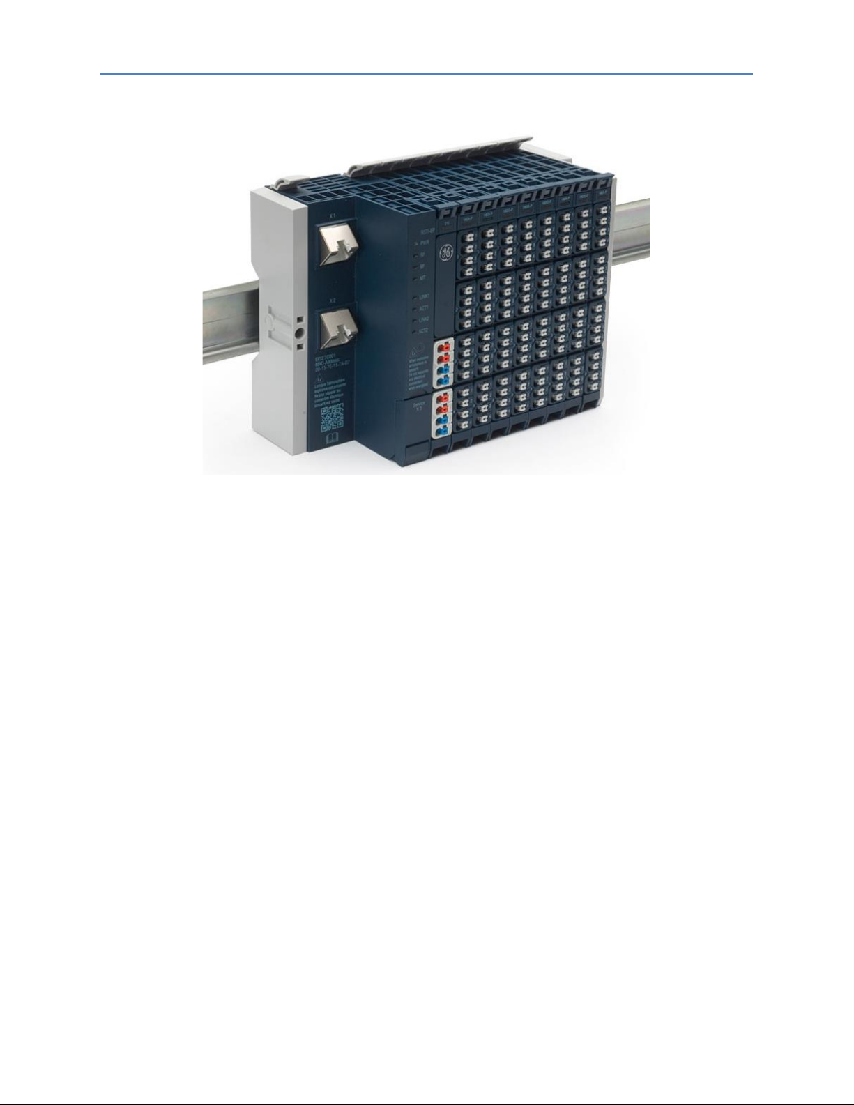
This manual describes the RSTi-EP remote I/O system. The products of the RSTi-EP series are
intended for use in industrial automation. A RSTi-EP station with network adapter and connected
modules is intended for the decentralized control of systems or sub-systems. Via the network
adapter every module of a station is integrated into a fieldbus structure and connected to the
primary control unit. The RSTi-EP products conform to protection class IP 20 (in accordance with DIN
EN 60529), they can be used in potentially explosive atmospheres rated as Zone 2 (as per Directive
2014/34/EU) and in safe zones.
The observance of the supplied documentation is part of the intended use. The products described in
this manual may only be used for the intended applications and only in connection with certified
third-party devices or components.
Introductory material may be found in this chapter along with a system overview. Chapter 2 provides
information about safety. Chapter 3 provides configuration instruction. Chapter 4 provides detailed
descriptions of the network adapters. Chapter 5 provides detailed descriptions of the I/O modules.
Chapter 6 provides information on installation and setup. Chapter 7 provides information on earthing
and shielding. Chapter 8 provides information on commissioning. Chapter 9 covers the Web Server.
Chapter 10 provides detailed instructions for replacing components. Chapter 11 describes
disassembly and disposal of the RSTi-EP station. Chapter 12 covers the LEDs and troubleshooting.
Chapter 13 provides ordering information for accessories and replacement parts. Appendix A is a
decimal/hexadecimal conversion table.
1.1 Document Updates
GFK-2958D RSTi-EP User Manual July 2017 7
Page 12
Chapter 1: Introduction
1.2 System Overview
The modular RSTi-EP system supports common fieldbus systems and conforms to IEC 61131-2. Each
station is assigned a bus address in the fieldbus structure. Only the network adapter is fieldbusspecific; the I/O modules are independent of the fieldbus.
Up to 64 active I/O modules can be combined in a RSTi-EP station. The largest expansion possible
depends on the maximum amount of data transmitted by the selected fieldbus, in particular the
configuration, parameter, or process data for the module types provided.
The following components belong to the RSTi-EP product series:
• Fieldbus network adapter (gateway): Head station for converting the respective fieldbus
protocol on the RSTi-EP system bus
• Active I/O modules:
o Modules with digital input (DI) or digital output (DO) with 2, 4, 8 or 16 channels
o Modules with analogue input (AI) or analogue output (AO) with 4 or 8 channels
o Pulse width modulation modules (PWM)
o Digital counter modules (CNT)
• Passive I/O modules (no fieldbus communication)
o 24 V power-feed modules (PF) for input or output current
o Potential distribution modules (AUX)
o Empty modules acting as placeholders (ES)
• Functional safety modules
o Safe power-feed modules (EP-19xx) 24 V for output current, providing one or two
inputs (with two channels each) for safety circuits
• Mechanical fixing elements
o End bracket
o End plate
GFK-2958D RSTi-EP User Manual 8
Page 13

Chapter 1: Introduction
Height (H)
Width (W)
Depth (D)
Network adapter
120.0 mm (4.72 in)
52.0 mm (2.05 in)
76.0 mm (2.99 in)
I/O module
120.0 mm (4.72 in)
11.5 mm (0.45 in)
76.0 mm (2.99 in)
End plate
120.0 mm (4.72 in)
3.5 mm (0.14 in)
76.0 mm (2.99 in)
End bracket
120.0 mm (4.72 in)
8.0 mm (0.32 in)
36.0 mm (1.42 in)
Dimensions of the RSTi-EP Components
1.2.1 Double-click Installation
The RSTi-EP station modules can be installed quickly and simply. When attaching the module to the
DIN rail, a clear clicking noise can be heard, which means that the module has clicked into place. In
the second step, which involves pushing the module being installed together with the neighboring
module, a further clicking noise indicates that the modules have been correctly connected to each
other.
GFK-2958D RSTi-EP User Manual 9
Page 14
Chapter 1: Introduction
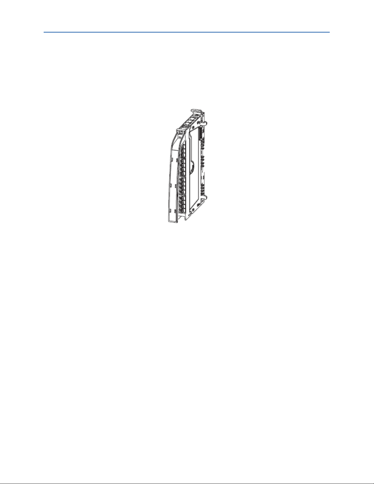
1.3 General Description of the Fieldbus Network Adapters
A fieldbus network adapter is used to connect the station I/O modules to the fieldbus. All of the data
traffic with the programmable logic controller including the diagnostic messages is exchanged via
the network adapter. The integrated power supply provides the network adapter and all connected
modules with power.
A detailed description of the individual network adapter types is available in Chapter 4, Detailed
Descriptions of the Fieldbus Network Adapter.
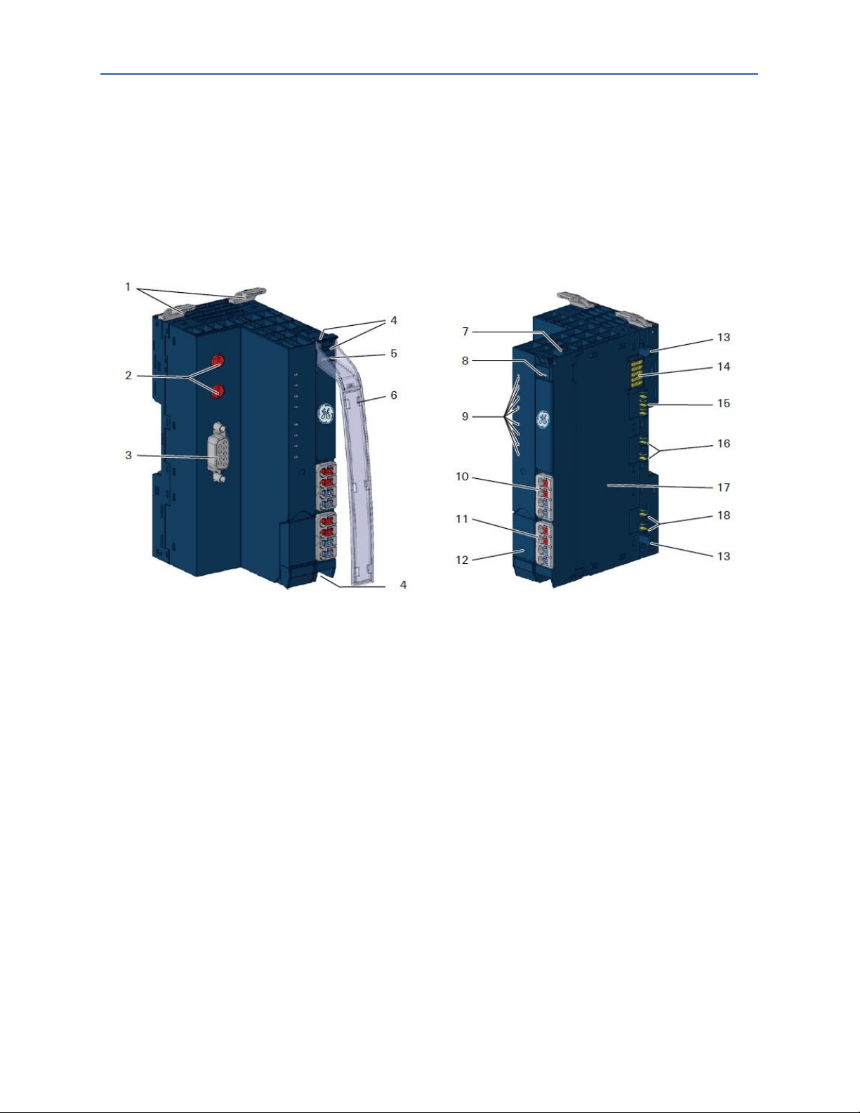
Fieldbus Network Adapter (example: EPXPNS001)
1 - Catch lever for securing the DIN rail
2 - Rotary switch (only PROFIBUS®)
3 - Data line connection (e.g. SUB-D socket)
4 - Seats for module markers
5 - Type designation
6 - Optional: swivel marker for labelling modules and channels
7 - Connector frame unlocking device
8 - LED power supply network adapter
9 – Network adapter status LEDs
10 - Power supply connector for the system and input modules
11 - Power supply connector for output modules
12 - Service flap
13 - Latching hook for latching onto module sides
14 - System bus
15 - System current path
16 - Input current path
17 - Type plate with block diagram
18 - Output current path
GFK-2958D RSTi-EP User Manual 10
Page 15

Chapter 1: Introduction
Type of connection
Spring-style
Single-wired, Fine-wired
Conductor cross-section 0.14 – 1.5 mm2
(AWG 16 – 26)
Configuration interface
USB 2.0
Dimensions
Height
120,0 mm (4.72 in)
(with release lever: 128,0 mm / 5,04 in)
Width
52,0 mm (2.05 in)
Depth
76,0 mm (2.99 in)
Protection class (DIN EN
60529)
IP 20
Flammability rating UL 94
V-0
Temperature data (Network
Adapter Power Supply)
Operation (horizontal
installation)
-20°C to +60°C (- 4 to +140 °F)
(8-A power supply)
-20°C to +55°C (- 4 to +131 °F)
(10-A power supply)
Operation (vertical installation)
-20°C to +55°C (- 4 to +131 °F)
(6-A power supply)
-20°C to +50°C (- 4 to +122 °F)
(8-A power supply)
Storage, transport
-40°C to +85°C (- 40 to +185 °F)
Humidity
Operation
95 %, non-condensing as per IEC 611312
Storage, transport
95 %, non-condensing as per IEC 611312
Air pressure
Operation
≥ 795 hPa (altitude ≤ 2000 m)
as per IEC 61131-2
Storage, transport
≥ 700 hPa (altitude ≤ 3000 m)
as per IEC 61131 2
Vibration resistance
5 Hz ≤ f ≤ 8.4 Hz: 3.5 mm amplitude as per IEC 60068-2-6
8.4 Hz ≤ f ≤ 150 Hz: 1 g acceleration as per IEC 60068-2-6
Shock resistance
15 g over 11 ms, half sinewave, as per IEC 60068-2-27
Potential isolation
Test voltage
max. 28,8 V within one channel
500 V DC field/system
Pollution severity level
2
Overvoltage category
II
Approvals and Standards
CULUS
Ordinary Locations
UL 508, CSA C22.2 No. 0-M91
CULUS
Hazardous Locations
Class 1 Division 2, Gr. A, B, C,
D
ISA 12.12.01: 2007
CSA C22.2 No. 213-M1987 (Reaffirmed
2008)
Potentially explosive
atmosphere Zone 2†
ATEX Directive 2014/34/EU
Explosion protection
IEC 60079-0:2012 and IEC 6007915:2010
EMC
IEC 61000 (partial standards as per the
requirements of IEC 61131 2)
FCC Compliance
47 CFR 15: 2011 (Class A)
†
Unless otherwise noted within the product-specific technical data.
1.4 General Technical Data for the Fieldbus Network Adapter
GFK-2958D RSTi-EP User Manual 11
Page 16

Chapter 1: Introduction
All product-specific technical data is available in the corresponding product description in Chapter 4, Detailed
Descriptions of the Fieldbus Network Adapters.
GFK-2958D RSTi-EP User Manual 12
Page 17
Chapter 1: Introduction
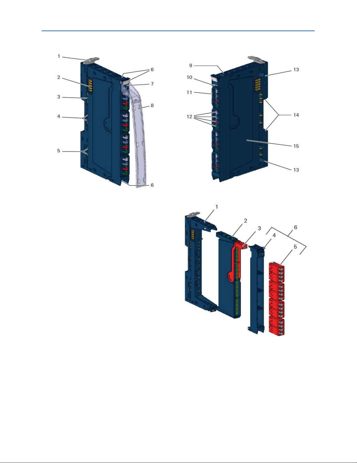
1 Catch lever for securing the DIN rail
2 System bus
3 System current path
4 Input current path
5 Output current path
6 Seats for module markers
7 Type designation
8 Optional: swivel marker for labelling modules and
channels
9 Connector frame unlocking device
10 Module status LED (collective message)
11 Connector
12 Channel status LEDs
13 Latching hook for latching onto module sides
14 DIN rail foot
15 Type plate
I/O Module Components
Color Coding
The removal levers for the electronic unit and the
connectors are color-coded as follows:
• Blue standard
• White power supply
• Red 230 V
• Yellow SIL products
1 Basic module
2 Electronic unit
3 Removal lever for electronic unit
4 Connector frame
5 Connector
6 Plug-in unit
A detailed description of the individual module types is available in Chapter 5, Detailed Descriptions of I/O
Modules.
1.5 General Description of I/O Modules
I/O module (Example EP-1214)
GFK-2958D RSTi-EP User Manual 13
Page 18
Chapter 1: Introduction
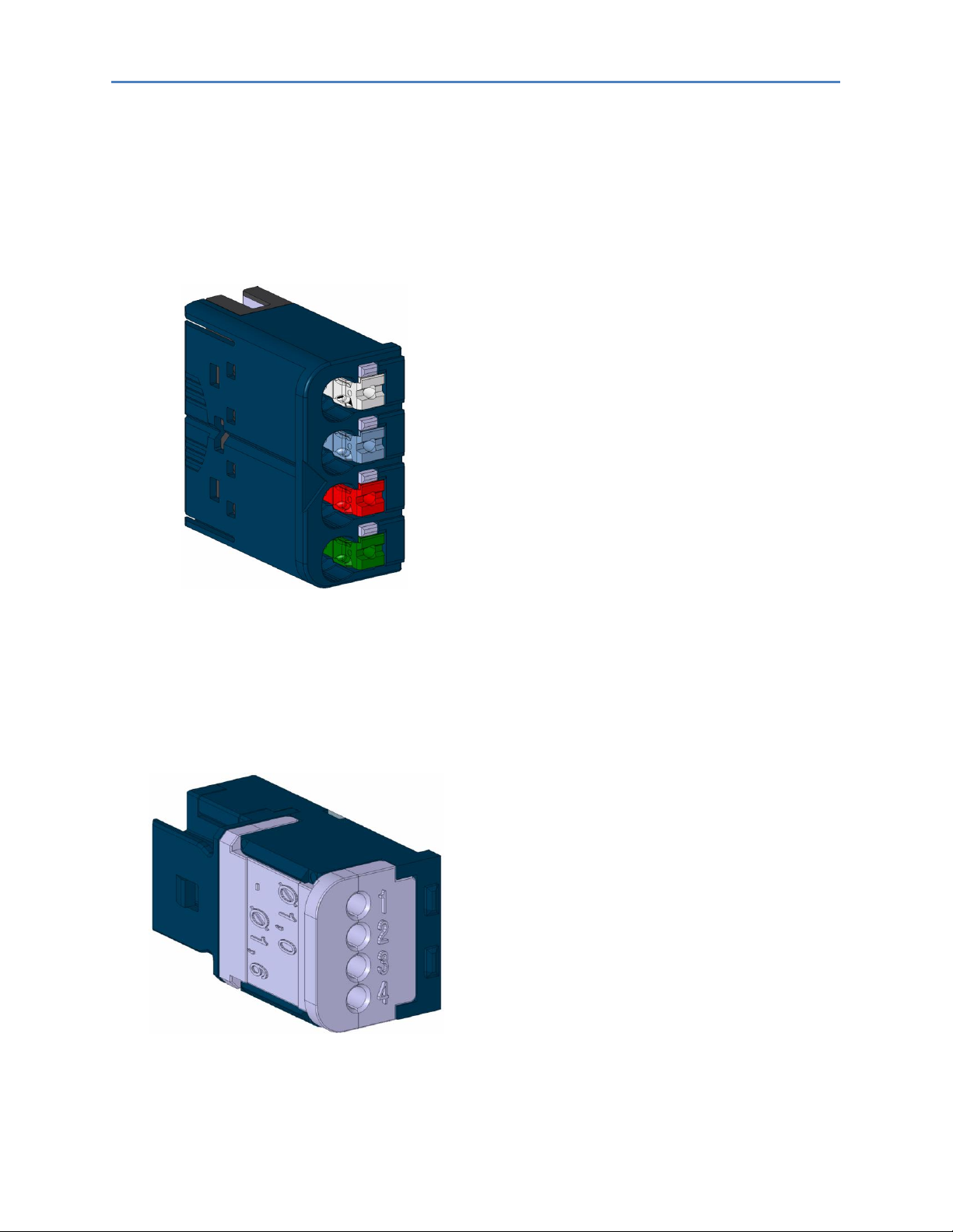
Connector with Four Conductor Connectors
Features and Specifications:
- conductor cross-section 0.14 to 1.5 mm²
(AWG 16 – 26)
- maximum ampacity: 10 A
- 4-pole
The pushers are color-coded for the following
connections:
• White Signal
• Blue GND
• Red 24 V DC
• Green Functional earth (FE)
Connector EP-8360 for HD Modules
Features and Specifications:
- conductor cross-section: 0.14 to 0.35 mm²
(AWG 22-26)
- insulation diameter 1.0 to 1.6 mm (0.04 to
0.06")
- maximum current capacity: 1 A
- 4-pole
1.5.1 Standard Connector
The connection frame can take up to four connectors, and four conductors can be connected to
each connector. Spring-style technology allows for fine-wired conductors with crimped wire-end
ferrules or ultrasonically welded conductors, each with a maximum cross-section of 1.5 mm², to be
inserted easily through the opening in the clamping terminal without having to use tools. To insert
fine-wired conductors without wire-end ferrules, the pusher must be pressed in with a screwdriver
(refer to the section, Wiring).
1.5.2 HD Connector EP-8360
The connection frame can take up to four times two HD connectors EP-8360, and qualified SAI
cables† with a cross-section from 0.14 to 0.35 mm
insulation displacement contact (IDC). (wiring refer to section, Wiring)
GFK-2958D RSTi-EP User Manual 14
2
can be connected to each connector via
Page 19

Chapter 1: Introduction
Description
Order No.
Digital input modules
Digital Input, 4 Points, Positive Logic 24VDC, 2,3, or 4 Wire
EP-1214
Digital Input, 8 Points, Positive Logic, 24VDC 2 Wire
EP-1218
Digital Input, 8 Points, Positive Logic, 24VDC 3 Wire
EP-1318
Digital Input, 4 Points, Positive Logic 24VDC, 2,3, or 4 Wire, Time stamp
EP-12F4
Digital Input, 4 Points 110/230 VAC (65 – 277 VAC), 2 Wire, Isolated
EP-1804
Digital output modules
Digital Output, 4 Points, Positive Logic 24VDC, 0.5A, 2,3, or 4 Wire
EP-2214
Digital Output, 4 Points, Positive Logic 24VDC, 2.0A, 2,3, or 4 Wire
EP-2614
Digital Output, 4 Points, Positive/Negative Logic 24VDC, 2.0A, 2,3, or 4 Wire
EP-2634
Analog input modules
Analog Input, 4 Channels Voltage/Current 16 Bits 2, 3, or 4 Wire
EP-3164
Analog Input, 4 Channels Voltage/Current 12 Bits 2, 3, or 4 Wire
EP-3124
Functional modules
2 Channels PWM Output, Positive Logic, 24VDC, 2.0 A
EP-5422
2 Channels PWM Output, Positive Logic, 24VDC, 0.5 A
EP-5442
1 Channel High Speed Counter, AB 100 kHz 1 DO 24VDC, 0.5A
EP-5111
2 Channel High Speed Counter, AB 100 kHz
EP-5112
2 Channel Frequency Measurement, 100 kHz
EP-5212
1 Channel Serial Communications, 232, 422, 485
EP-5261
1 Channel SSI Encoder, BCD or Gray-Code Format, 5/24 VDC
EP-5311
Potential distribution modules
Power Module, 16 Channels 24VDC Potential Distribution +24 VDC from Input Current Path
EP-711F
Power Module, 16 Channels 24VDC Potential Distribution +24 VDC from Output Current Path
EP-751F
Power Module, 16 Channels 24VDC Potential Distribution +0VDC from Input Current Path
EP-710F
Power Module, 16 Channels 24VDC Potential Distribution +0VDC from Output Current Path
EP-750F
1.5.3 Cable Protection
The modules listed in the following table do not have a fused sensor/actuator power supply. Here, all
cables to the connected sensors/actuators must be fused corresponding to their conductor crosssections (as per Standard DIN EN 60204-1, section 12).
GFK-2958D RSTi-EP User Manual 15
Page 20

Chapter 1: Introduction
Type of connection
Spring-style
Single-wired, fine-wired
Conductor cross-section
0.14 – 1.5 mm2 (AWG 16 – 26)
IDC (EP-3368, EP-3468)
Single-wired, fine-wired
Conductor cross-section
0.14 – 0.35 mm2 (AWG 22 – 26)
Dimensions
Height
4.72 in (120.0 mm)
w/ release lever: 128.0 mm (5.04 in)
Width
11.5 mm (0.45in)
Depth
76.0 mm (2.99 in)
Protection class
(DIN EN 60529)
IP 20
Flammability rating UL 94
V-0
Temperature data
Operation
-20°C to +60°C (- 4 to +140 °F)
Storage, transport
-40°C to +85°C (- 40 to +185 °F)
Humidity
Operation, storage, transport
5 % to 95 %, non-condensing
as per IEC 61131-2
Air pressure
Operation
≥ 795 hPa (altitude ≤ 2000 m)
as per IEC 61131-2
Storage, transport
≥ 700 hPa (altitude ≤ 3000 m)
as per IEC 61131-2
Vibration resistance
5 Hz ≤ f ≤ 8.4 Hz: 3.5-mm amplitude as per IEC 60068-2-6
8.4 Hz ≤ f ≤ 150 Hz: 1-g acceleration as per IEC 60068-2-6
Shock resistance
15 g over 11 ms, half sinewave, as per IEC 60068-2-27
Potential isolation
Test voltage
max. 28.8 V within one channel
500 V DC field/system
Pollution severity level
2
Overvoltage category
II
Approvals and Standards
cULus Ordinary Locations
UL 508, CSA C22.2 No. 0-M91
CULUS
Hazardous Locations
Class 1 Division 2, Gr. A, B, C, D
ISA 12.12.01: 2007
CSA C22.2 No. 213-M1987 (Reaffirmed 2008)
Potentially explosive atmosphere
Zone 2†
ATEX Directive 2014/34/EU
Explosion protection
IEC 60079-0:2012 and
IEC 60079-15:2010
EMC
IEC 61000
(partial standards as per the requirements of
IEC 61131-2)
FCC Compliance
47 CFR 15: 2011 (Class A)
Type of connection
Spring-style
Single-wired, fine wired
ICES Compliance
ICES-003:2012 (Class A)
PLC
IEC 61131-2
†
Unless otherwise noted within the product-specific technical data.
All product-specific technical data is available in the corresponding product description in Chapter 5, Detailed Descriptions
of I/O Modules.
1.6 General Technical Data for I/O Modules
GFK-2958D RSTi-EP User Manual 16
Page 21
Chapter 1: Introduction
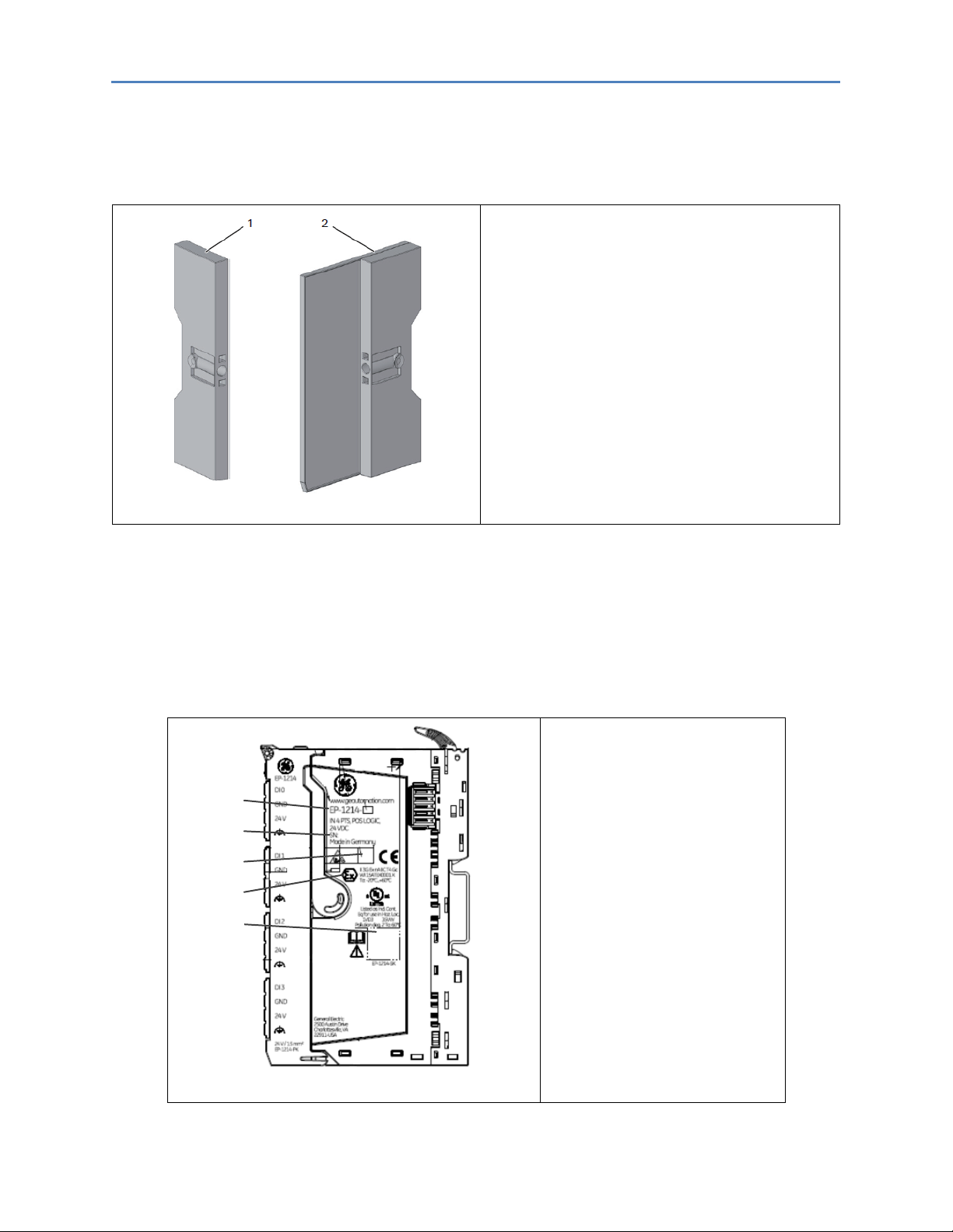
RSTi-EP station fixing elements
1 End bracket (left end, on the network adapter
side)
2 Termination kit with end plate and end
bracket (right end)
For vertical installation, a special end bracket
must also be installed below the station.
5
4
3
2
1
Type Plate (Example of EP-1214)
1 Product number
2 Serial number
3 Manufacturing code
4 ATEX marking
5 QR code
1.7 Mechanical Fixing Elements
The station is fixed in the installation position by an end bracket at either side. The last I/O module is
protected against dust by a cover plate, into which the second end bracket is inserted and screwed
to the mounting rail. Every RTSi-EP network adapter is supplied with a termination kit.
1.8 Type Plate
Each network adapter and each module features a type plate, which includes identification
information, the key technical specifications and a block diagram. In addition, a QR code allows for
direct online access to the associated documentation. The software for reading the QR code must
support inverted QR codes. A breakdown of the serial numbers can be found in the table provided in
the annex.
GFK-2958D RSTi-EP User Manual 17
Page 22
Chapter 1: Introduction
1.9 Markers
A wide range of markers are available as accessories for labelling equipment.
1.9.1 Swivel Marker
RSTi-EP I/O Label Markers (EP-8100) allow for modules and all respective channels and lines to be
labelled in detail. They are attached to the connector frame.
Module with Swivel Marker
The following labels are available for the labelling:
• Paper labels for printing with laser printers (Part No. EP-8101)
o White
o Yellow
GFK-2958D RSTi-EP User Manual 18
Page 23

Chapter 1: Introduction
Notes
GFK-2958D RSTi-EP User Manual 19
Page 24

Safety
This section includes general safety instructions for handling the RSTi-EP system. Specific safety
instructions for specific tasks and situations are given at the appropriate places in the
documentation.
When using remote I/O RSTi-EP modules, refer to the Module for Functional Safety Manual (GFK-2956).
2.1 General Safety Notice
Work on the RSTi-EP products may only be performed by qualified personnel with the support of
trained persons. As a result of their professional training and experience, an personnel is qualified to
perform the necessary work and identify any potential risks.
Before any work is carried out on the products (installation, maintenance, retrofitting), the power
supply must be switched off and secured against being switched on again. Work may be carried out
with safety extra-low voltage.
The manual provided with the equipment shall be followed in detail to assure proper and safe
operation.
A stabilized 24V DC power supply shall be used.
All field wiring intended for connection to the power terminal shall consist of copper conductors with
the insulation locally removed. Additional intermediate connecting parts, other than ferriles, shall not
be used.
When working during continued operations, the emergency stop mechanisms must not be made
ineffective. If you need technical help, contact Technical Support. For phone numbers and email
addresses, refer to the General Contact Information page in the front of this manual.
If a malfunction on a RSTi-EP product cannot be fixed after following the recommended measures
(refer to the Chapter, LED Indicators and Troubleshooting), the product in question must be sent back
to GE. GE does not assume any liability if the base or electronic module has been tampered with.
2.1.1 Electrostatic Discharge
RSTi-EP products can be damaged or destroyed by electrostatic discharge. When handling the
products, the necessary safety measures against electrostatic discharge (ESD) according to IEC
61340-5-1 and IEC 61340-5-2 must be observed.
All devices are supplied in ESD-protected packaging. The packing and unpacking as well as the
installation and disassembly of a device may only be carried out by qualified personnel and in
accordance with the ESD information.
2.1.2 Open Equipment
RSTi-EP products are open equipment (having live electrical parts that may be accessible to users)
that may only be installed and operated in lockable housings, cabinets or electrical operations
rooms. Only trained and authorized personnel may access the equipment.
For applications requiring functional safety or in order to maintain compliance with the ATEX
Directive [Class 1, Zone 2 area (Category 3)], the surrounding housing must meet at least IP 54.
The standards and guidelines applicable for the assembly of switch cabinets and the arrangement of
data and supply lines must be complied with.
GFK-2958D RSTi-EP User Manual July 2017 20
Page 25

Chapter2: Safety
2.1.3 Fusing
The operator must set up the equipment so that it is protected against overloading. The upstream
fuse must be designed such that it does not exceed the maximum load current. The maximum
permissible load current of the RSTi-EP components can be found in the technical data.
In the case of modules without fused sensor/actuator power supplies, all lines to the connected
sensors/actuators must be fused corresponding to their conductor cross-section (as per DIN VDE
0298 Part 4).
To meet UL-specifications in accordance with UL 248-14, a UL-certified automatic fuse or a 10 A fuse
with a medium time-lag must be used.
All connections of the RSTi-EP components are protected against voltage pulses and overcurrent in
accordance with IEC 61131-2, Zone B. The operator has to decide whether additional overvoltage
protection according to IEC 62305 is required. Voltages that exceed +/-30 V may cause the
destruction of network adapters and modules.
A feed-in power supply with secure isolation must be used.
2.1.4 Earthing (functional earth FE)
Each RSTi-EP I/O module is fitted with an FE spring on the underside which creates an electrical
connection to the DIN rail. In order to establish a secure connection, the assembly must be carried
out carefully in accordance with the instructions (refer to Chapter 6, Installation). The module is
earthed by connecting the DIN rail to the protective earth via the earth terminal.
Modules EP-700F, EP-1214, EP-2214, EP-3124 and EP-3164 have connections with green pushers. An
FE potential is also provided at these connections. They must not be used as a PE.
2.1.5 Shielding
Shielded lines are to be connected with shielded plugs and fixed on a shield bus in compliance with
the relevant standard (refer to Chapter 7, Earthing and Shielding).
2.1.6 Overcurrent
Potentials of network adapters and power-feed modules must be disconnected either simultaneously
or in the order 24 V supply first, then the GND potential.
2.2 Intended Use
The products of the RSTi-EP series are intended for use in industrial automation. A RSTi-EP station
with network adapter and connected modules is intended for the decentralized control of systems or
sub-systems. Via the network adapter every module of a station is integrated into a fieldbus
structure and connected to the primary control unit. The RSTi-EP products conform to protection
class IP 20 (in accordance with DIN EN 60529), they can be used in potentially explosive atmospheres
rated as Zone 2 (as per Directive 2014/34/EU) and in safe zones.
The observance of the supplied documentation is part of the intended use. The products described in
this manual may only be used for the intended applications and only in connection with certified
third-party devices or components.
GFK-2958D RSTi-EP User Manual 21
Page 26

Chapter2: Safety
2.3 Use in a Potentially Explosive Atmosphere
If RSTi-EP products are used in potentially explosive atmospheres, the following notes are also
applicable:
• Staff involved in assembly, installation and operation must be qualified to perform safe
work on electrical systems protected against potentially explosive atmospheres.
• The remote I/O-System RSTi-EP shall only be used in an area of not more than pollution
degree 2, as defined in IEC 60664-1.
• For applications in potentially explosive atmospheres, the requirements according to IEC
60079-15 must be observed, in particular the housing enclosing the system must meet
the requirements of explosion protection type Ex n or Ex e and protection class IP54. The
IP54 enclosure must be accessible only by the use of a tool.
• Sensors and actuators that are located in Zone 2 or in a safe zone can be connected to
the RSTi-EP station.
• The ambient temperature range -20°C to +60°C shall not be exceeded.
• When the temperature under rated conditions exceeds 70 °C at the conductor or conduit
entry point, or 80 °C at the contact, the temperature specification of the selected cable
shall be in compliance with the actual measured temperature values.
• A stabilized 24V DC power supply with double or reinforced insulation shall be used.
• When using relay modules EP-2714, EP-2814, and EP-1804 in explosive atmosphere:
o Device shall be installed in an environment free of condensation, corrosives and
conducting dusts.
o If the switching or input voltage exceeds 63V, a transient protection device shall be
provided that limits the transients to a peak voltage of 500V or less.
• For EP-2714 (Relay Module) only:
o Since relays are subject to wear, it must be ensured, by appropriate maintenance
intervals, that the temperatures do not exceed the limits of temperature class T4.
Note: A contact resistance of more than 110 milli-ohm will be considered as a fault.
o Resistive Loads Only
o Transient protection shall be provided that is set at a level not exceeding 140% of the
peak rated voltage value at the supply terminals to the equipment.
• A visual inspection of the RSTi-EP station is to be performed once per year.
• A visual inspection of the RSTi-EP station is to be performed once per year.
• If mounted in other directions than horizontal (reference mounting rail), restrictions to the
max. operating temperature, max. output currents may apply.
• While explosive atmosphere is present:
o No electrical connection shall be separated in energized condition.
o The USB interface shall not be used.
o Dip-switches, binary-switches and potentiometers shall not be actuated.
• Only power supplies with secure isolation shall be used.
• Refer manufacturers manual.
GFK-2958D RSTi-EP User Manual 22
Page 27
Chapter2: Safety
Warning
EXPLOSION HAZARD - SUBSTITUTION OF COMPONENTS MAY IMPAIR
SUITABILITY FOR CLASS I, DIVISION 2.
WHEN IN HAZARDOUS LOCATIONS, TURN OFF POWER BEFORE REPLACING
OR WIRING MODULES; AND
DO NOT CONNECT OR DISCONNECT EQUIPMENT UNLESS POWER HAS
BEEN SWITCHED OFF OR THE AREA IS KNOWN TO BE NONHAZARDOUS.
Altitude (m, ft)
Factor for Temperature Derating
< 2000 m (6561.68 ft)
1
2001 to 3000 m (6564.96 to 9842.52 ft)
0.88
3001 to 4000 m (9845.80 to 13123.36 ft)
0.78
4001 to 5000 m (13126.64 to 16404.20 ft)
0.68
2.3.1 ATEX Zone 2
The module must be mounted in an enclosure certified in accordance with EN60079-15 for use in
Zone 2, Group IIC and rated IP54. The enclosure shall only be able to be opened with the use of a tool.
2.3.2 ATEX & IECEx Marking
WI 15ATEX0001 X
II 3 G Ex nA T4 Gc
II 3 G Ex nA nC T4 Gc
IECEx ULD 16.0022x
Ta: -20°C to +60°C
2.4 Legal Notice
The RSTi-EP series products are CE-compliant in accordance with Directive 2014/30/EU (EMC
Directive) and Directive 2014/35/EU (Low Voltage Directive). They also meet the requirements of the
ATEX Directive 2014/34/EU.
2.5 Use of RSTi-EP Stations Above 2000m Sea Level
The RSTi-EP remote I/O system is able to operate in height >2000 m (6561.68 ft) above sea
level, with the following limitations:
There is a derating for ambient temperatures while the RSTi-EP Station is in operating
mode. Refer to the following derating table.
Example:
Height 3000 m (9842.52 ft): maximum operational temperature is 60° C (140 °F) x 0.88 = 52.8°C
(136.76 °F) at maximum 8A.
GFK-2958D RSTi-EP User Manual 23
Page 28
Configuration
3.1 Order and Arrangement of the Modules
The RSTi-EP system elements are designed to be installed on a profile rail according to EN 60715 [1.4
x 0,26 in (35 × 7.5 mm)], a steel strip in accordance with Annex A of EN 60715, or a tin-plated steel
strip.
Note: A RSTi-EP station may be built up to a maximum length of 3.28 ft (1 m). Therefore, at most
82 modules (including max. 64 active modules) can be aligned on a network adapter.
The RSTi-EP station is usually installed on a horizontally positioned DIN rail.
Installation Position of the RSTi-EP Station on the DIN Rail (Horizontal Installation)
Installation on vertically positioned DIN rails is also possible. In this case however, the heat
dissipation is reduced such that the derating values change (refer to the section Current Demand and
Power Supply). In the case of vertical mounting, the network adapter must always be arranged as the
first module at the bottom and secured with an end bracket for vertical mounting.
GFK-2958D RSTi-EP User Manual July 2017 24
Page 29
Chapter 3: Configuration
Attention
A maximum of three passive modules (potential distribution module, powerfeed module or blank module) may be placed in successive positions. Then at
least one active module must follow.
Installation Position of the RSTI-EP Station on the DIN Rail (Vertical Installation)
A RSTi-EP station may only be installed in this sequence (starting from the left/bottom):
• End bracket
• Network adapter
• Up to 82 modules (including max. 64 active modules)
• End plate and end bracket
3.1.1 Arrangement of Safe Power-feed Modules
A safe power-feed module EP-19xx module can be positioned anywhere in the RSTi-EP station. All the
following output modules (except for the EP-2814 and EP-2714 relay modules) up to the next EP-19xx
module are safely disconnected (safety segment). Multiple EP-19xx modules/safety segments can be
arranged within a station.
Note: When using RSTi-EP EP-19xx modules, also refer to the Modules for Functional Safety Manual
(GFK-2956).
GFK-2958D RSTi-EP User Manual 25
Page 30
Chapter 3: Configuration
Attention
Depending on how the station shielding is implemented, the specified
distances may have to be made larger, where necessary.
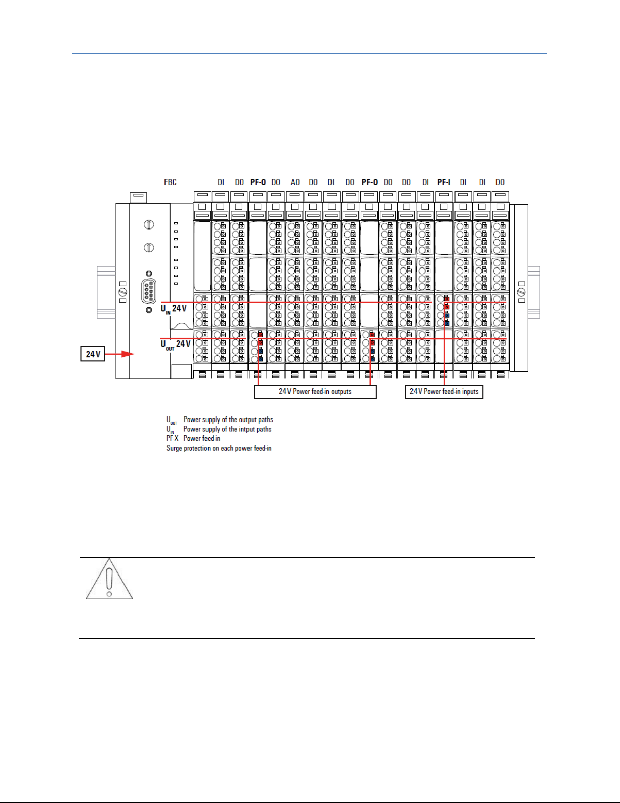
3.1.2 Power Supply Concept
The RSTi-EP system uses three internal current paths as described in the following chapter, Detailed
Descriptions of the Fieldbus Network Adapters. Input and output paths are supplied separately, therefore a
custom-fit refreshing by power-feed modules is easily feasible.
The following figure shows the general supply concept. For detailed description and calculation of the current
demand refer to the sections, Example Calculation for the Power Supply and Calculation of Power Loss of
this manual.
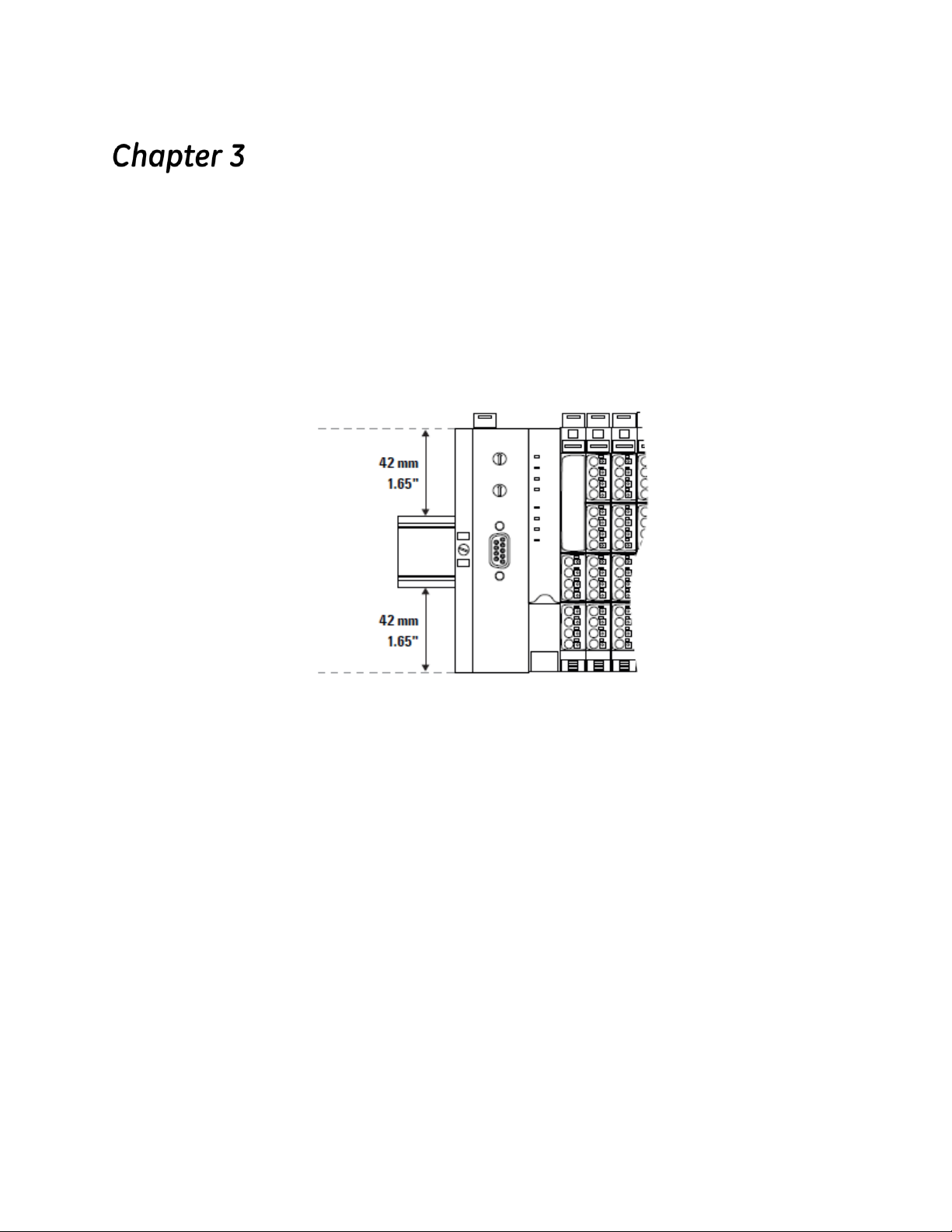
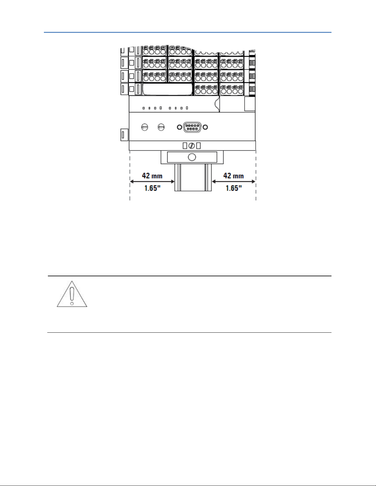
3.2 Installation Distances
In order to be able to carry out the installation and subsequent maintenance work and to ensure
sufficient ventilation, the RSTi-EP station must be installed while observing the following minimum
distances (refer to the following figures).
The minimum permissible conductor bending radii must also be observed. Earth terminals already
installed can be ignored when calculating the distance.
GFK-2958D RSTi-EP User Manual 26
Page 31

Chapter 3: Configuration
Minimum Distances for Horizontal Installation
Minimum Distances for Vertical Installation
Minimum Distance for Electrical Cabinet Door (Without/With Swivel Marker)
GFK-2958D RSTi-EP User Manual 27
Page 32

Chapter 3: Configuration
Height:
120 mm (4.72 in)
+ 40 mm (2 x 1.57 in)
= 200 mm (7.87 in)
distances at top and bottom
Width:
8 mm (1.57 in)
+ 52 mm (2.05 in)
+ n x 11.5 mm (0.45 in)
+ 11.5 mm (0.45 in)
+ 2 x 20 mm (0.79 in)
= 111.5 mm (4.39 in) + n x 11.5 mm (0.45 in)
end bracket
network adapter
n modules
end plate and end bracket
distances to the sides
3.2.1 Calculation of Space Requirements
The space requirements for a RSTi-EP station with n modules (horizontal installation) is calculated as
follows:
For vertical installation interchange height and width. When calculating the width, 4.5 mm (0.18 in)
for the must be added for the end bracket.
3.3 Use in a Potentially Explosive Atmosphere
If the RSTi-EP is used in a potentially explosive atmosphere rated as Zone 2, the housing must meet
the requirements of explosion protection type Ex n or Ex e and protection class IP54. Sensors and
actuators that are located in Zone 2 or in a safe zone can be connected. All cable glands on the
housing must be approved for Ex e.
GFK-2958D RSTi-EP User Manual 28
Use in a Potentially Explosive Atmosphere
Page 33

Chapter 3: Configuration
Horizontal
Vertical
Network Adapter power supply
60 °C / 140 °F : 2 x 8 A
55 °C / 131 °F : 2 x 10 A
55 °C / 131 °F : 2 x 6 A
50 °C / 122 °F : 2 x 8 A
Power-feed module power supply
60 °C / 140 °F : 1 x 10 A
55 °C / 131 °F : 1 x 8 A
3.3.1 ATEX & IECEx Marking
II 3 G Ex nA IIC T4 Gc
II 3 G Ex nA nC IIC T4 Gc
WI 15ATEX0001 X
Ta: -20°C ... +60°C
3.4 Spring-style System Cabling
RSTi-EP modules (except HD modules) and network adapters are equipped with the spring-style
connector system. Single-strand and fine-strand lines with wire-end ferrules can be inserted without
the need for a tool. Lines with a cross-section measuring between 0.14 mm2 and 1.5 mm2 (AWG 26 –
16) can be connected.
The external dimensions of the crimped wire-end ferrules must conform to IEC 60947-1.
3.5 Current Demand and Power Supply
The RSTi-EP system uses three internal current paths:
The ISYS system current path supplies the communication part of the I/O modules; it is fed from the
network adapter input supply and cannot be interrupted by any module. The maximum currentcarrying capacity of ISYS allows a RSTi-EP station to be expanded with a maximum of 64 active
modules without having to refresh the power.
The IIN input current path supplies the input circuit of the input modules as well as the connected IS
sensors. The current must be refreshed with EO-7631 (power feed in) modules as required. These EP7631 modules isolate the input current path towards the left (towards the network adapter), and as a
result start a new electricity segment towards the right.
The IOUT output current path supplies the output circuit of the output modules with power, as well as
the connected IL actuators. The current must be refreshed with the EP-7641 (power feed-out), as
required. These EP-7641 modules isolate the output current path to the left (towards the network
adapter), and as a result start a new electricity segment to the right.
Note: The design of the power supply being used must take start-up peaks into account.
3.5.1 Power Supply Derating
The power supply is restricted according to the temperature. The following values apply for the
horizontal and vertical positioning of the RSTi-EP station:
GFK-2958D RSTi-EP User Manual 29
Temperature-dependent Values for the Power Supply
Page 34

Chapter 3: Configuration
Product group
Product
I
SYS
IIN
I
OUT
IS
IL
Network adapters
EPXPBS001
100 mA
EPXPNS001
116 mA
EPXETC001
110 mA
EPXMBE001
112 mA
Digital
input modules
EP-1214
8 mA
18 mA
x
EP-1218
8 mA
30 mA
x
EP-1318
8 mA
30 mA
x
EP-125F
8 mA
52 mA
EP-12F4
8 mA
18 mA
x
EP-1804
8 mA
Digital
output modules
EP-2214, EP-2714, EP-2634
8 mA
20 mA
x
EP-2218
8 mA
35 mA
x EP-225F, EP-2614
8 mA
25 mA
x
EP-2814
11 mA
Analog
input modules
EP-3164, EP-3124, EP-3264
8 mA
25 mA
x
EP-3804, EP-3704, EP-3368, EP-3468
8 mA
20 mA
Analog
output modules
EP-4164, EP-4264
8 mA
85 mA
Functional modules
EP-5111, EP-5112
8 mA
35 mA
x
EP-5212
8 mA
35 mA
x x
EP-5422, EP-5442
8 mA
40 mA
EP-5261
8 mA
16 mA
EP-5311
8 mA
25 mA
Power-feed modules
EP-7641
10 mA
EP-7631
10 mA
EP-1901, EP-1902, EP-1922
8 mA
45 mA
x
Potential distribution
modules
EP-751F - - - - - EP-711F - - - -
-
I
SYS
IIN
I
OUT
IS
IL
x
Current consumption from the system current path
Power consumption from input current path
Power consumption from output current path
Current demand of the connected sensors
Current demand of the connected actuators
Must be included when calculating the power supply
Current Demand
GFK-2958D RSTi-EP User Manual 30
Page 35

Chapter 3: Configuration
I
SYS
network adapter
+ (I
SYS
+ IIN ) + (IS x g) module 1
+ (I
SYS
+ IIN ) + (IS x g) module 2
+ Σ ((I
SYS
+ IIN ) + (IS x g)) modules 3 to
4
= Cumulative current demand
I
SYS
Current consumption from the system current path
IIN Current consumption from the input current path
IS Power supplies for the connected sensors
((IIN + IS module x) x g)
+ ((IIN + IS module y) x g)
+ Σ ((IIN + IS) x g) n modules
= Cumulative current demand
I
SYS
Current consumption from the system current path
IS Power supplies for the connected sensors
3.6 Example Calculation for the Power Supply
The power supply must be calculated individually for each station installation. Therefore the
simultaneity factor g and the current demand of each module, as well as the devices to be
connected must be established (refer to the example calculation table).
In the example station, an EPXPNS001 network adapter is configured with four EP-1214 modules
and eight EP-2218 modules. The cumulative current demand for each module is now calculated to
determine whether and at which point a EP-7631 power-feed module must be positioned to refresh
the current path. A power-feed module must always be used where the current demand
exceeds 10 A.
Note: The power refresh must be separately calculated for the input and output current paths. The
system voltage need not be considered during this step.
Note: Use the RSTi-EP Power Supply Configuration Guide to perform this calculation automatically.
3.6.1 Calculation of the Current Demand for the Input Current
The current consumption of the network adapter must be considered for the main power supply,
and the sum of consumption values is multiplied by the simultaneity factor g for each following
module:
In the case of an additional power supply (power refresh) with a EP-7631 power-feed module, only
the sensor power supplies and the module current consumption have to be considered:
GFK-2958D RSTi-EP User Manual 31
Page 36

Chapter 3: Configuration
(I
OUT
+ (IL x g) module 1
+ (I
OUT
+ (IL x g) module 2
+ Σ (I
OUT
+ (IL x g)) n modules
= Cumulative current demand
I
OUT
module current consumption from the output current
path
IL Current demand of the connected actuators
3.6.2 Calculation of the Current Demand for the Output Current
The current consumption of each module and the current demand of the connected actuators must
be considered for the output current. There is no difference in the calculation of the main power
supply and power refresh:
Example:
The values in the following table are used to calculate the current demand of the example station
(cumulative for each module). The input current is:
Module 1:
I = 0.116 A + (0.008 A + 0.012 A) + (0.06 A x 1) = 0.196 A
Module 2:
I = 0.196 A + (0.008 A + 0.012 A) + (0.06 A x 1) = 0.276 A
The values for the other modules are calculated accordingly. The result shows that the accumulated
value for up to 12 modules remains under 10 A, and therefore a power supply module need not be
used for the input current path. Results for the output current path:
Module 5:
I = 0.015 A + (0.5 A x 2) = 1.015 A
Module 6:
I = 1.015 A + (0.015 A + (0.5 A x 4) = 3.03 A
Module 10:
I = 6.175 A + (0.015 A + (0.5 A x 4) = 8.19 A
Module 11 (without power refresh):
I = 8.19 A + (0.015 A + (0.5 A x 4) = 10.205 A
Therefore the available 10 A would be exceeded. As a result, an EP-7641 power supply module must
be positioned as the 11th module, which will supply the required power to the subsequent modules
after the power feed module. Unused current values may not be included.
Module 11 (as per PF-O):
I = (0.015 A + (0.5 A x 4) = 2.015 A
Module 12 (as per PF-O):
I = 2.015 A (0.015 A + (0.5 A x 4) = 4.030 A
GFK-2958D RSTi-EP User Manual 32
Page 37

Chapter 3: Configuration
Module
no.
GE part
number
I
SYS
IIN
I
OUT
IS
IL
Simultaneity
factor
g
Cumulative
current
demands
of the input
current
path
Cumulative
current
demand
of the
output
power path
network
adapter
Cumulative
current
demand of
the
EP-7641
output
power
path
EPXPNS
001
0.116 0.116 0
1
EP-1214
0.008
0.018
0.06 1
0.202 0
2
EP-1214
0.008
0.018
0.06 1
0.288 0
3
EP-1214
0.008
0.018
0.12 1
0.434 0
4
EP-1214
0.008
0.018
0.18 1
0.64 0
5
EP-2218
0.008
0.035
2 0.5
0.648
1.035
6
EP-2218
0.008
0.035
4 0.5
0.656
3.07
7
EP-2218
0.008
0.035
3 0.5
0.664
4.605
8
EP-2218
0.008
0.035
2 0.5
0.672
5.64
9
EP-2218
0.008
0.035
1.2 0.5
0.68
6.275
10
EP-2218
0.008
0.035
4 0.5
0.688
8.29
EP-7641
11
EP-2218
0.008
0.035
4 0.5
0.696
2.035
12
EP-2218
0.008
0.035
4 0.5
0.70 4.07
I
SYS
IIN
I
OUT
IS
IL
Current consumption from the system power supply
Power consumption from input current path
Power consumption from output current path
Current demand of the connected sensors
Current demand of the connected actuators
The current demand is just under 10 A. The output current path must therefore be refreshed before the
11th module.
10 A is supplied by the EP-7641 module. The 1.81 A calculated as remaining after the 10th module must not be
added to the 10 A after the EP-7641 module!
Example Calculation for the Current Demand (all Current Values in A)
GFK-2958D RSTi-EP User Manual 33
Page 38

Chapter 3: Configuration
P0
Static power loss in the network adapter
2,3 W
N
Number of modules
P
mod
Power loss due to module supply from the system current path
0,02 W
P
module
Maximum power loss module
Iin
Current fed in through the input current path
ΔVin
Voltage drop across the contacts in the input current path
0,18 V
I
out
Current fed in through the output current path
ΔV
out
Voltage drop across the contacts in the output current path
0,18 V
3.7 Calculation of Power Loss
The power loss of the network adapter is calculated als follows:
P
network adapter
The power loss of a RSTi-EP station is calculated using the power loss of the network adapter and the
power loss of the individual modules. It depends on the current in both current paths. It is assumed
that there is a maximum power loss of 2 watts for the module
Maximum values were assumed for these calculations. If you need detailed calculations, please
contact GE technical support or GlobalCare.
P
= P
station
= P0 + N * P
network adapter
mod
+ N * P
+ Iin * ΔUin + I
module
out
* ΔU
out
3.7.1 Calculation of Power Loss for Use in a Potentially Explosive
Atmosphere
The module specific data, needed to calculate the output power loss, are provided in the ATEX
certificate which you can download from the GE website.
3.8 Feedback Energy in DO Modules
With digital output modules, power is fed back through the channels when inductive loads are
switched off. The respective permissible breaking energy is noted in the technical data of the DO
modules. Depending on the switching frequency, the breaking energy leads to additional energy loss
in the output module.
If the maximum permissible feedback energy for a module is exceeded, the module shuts down
temporarily.
Note: Feedback energy can be prevented by installing external freewheeling protection. With it, the
same switching rate can be achieved with an inductive load as with a resistive load.
GFK-2958D RSTi-EP User Manual 34
Page 39

Chapter 3: Configuration
P
Feedback energy of the module
Ni
Switching cycles of Channel i in 1/seconds
Ei
Feedback energy when shutting off Channel i during a shutdown
procedure
Ii
Current through the load connected to Channel i
Li
Inductance of the load connected to Channel i
3.8.1 Calculation of Feedback Energy
The feedback energy for a digital output module can be calculated as follows:
P = Σ
all channels
Once the maximum permissible feedback energy E
1/2 ni * Li * Ii²
is reached, the module shuts down.
max
Maximum Feedback Energy Varies with Ambient Temperature
GFK-2958D RSTi-EP User Manual 35
Page 40

Chapter 3: Configuration
Product
Part No.
Parameter
Optional values
Default value
PROFIBUS DP-V1
Network Adapter
EPXPBS001
DP-Alarm mode
V0 / V1
V1
DP alarm mode V0
For mode V0, the alarm triggers are set in
the parameter data.
Diagnostic alarm†
enabled / disabled
disabled
Process alarm†
enabled / disabled
disabled
Hot-plug alarm†
enabled / disabled
enabled
†
These switches are always selectable, but they only have a function in mode
V0. Diagnostic messages are generated which are not acknowledged by the
PLC.
DP alarm mode V1
In mode V1, the alarm triggers are set in
the engineering environment.
Diagnostic alarm
††
enabled / disabled
disabled
Process alarm
††
enabled / disabled
disabled
Hot-plug alarm
††
enabled / disabled
enabled
††
These switches can be selected only in mode V1, in V0 they are inactive.
Diagnostic messages are generated which are acknowledged by the PLC.
Identifier-related diagnosis
†††
enabled / disabled
enabled
Channel-related diagnosis
†††
enabled / disabled
enabled
Module status
†††
enabled / disabled
enabled
†††
A diagnostic block is attached to the diagnostic message.
Data format
Motorola / Intel
Motorola
Fieldbus error output behavior
All outputs off /
activate replacement
values / retain last
value
All outputs off
Module behavior during hot
swap
Continue data
exchange /
behavior as with
fieldbus error
Continue data
exchange
Product
Part No.
Parameter
Optional values
Default value
PROFINET IRT
Network Adapter, 2
Cu RJ45 Ports, 1024
bytes (Input + Output)
EPXPNS001
Process alarm
enabled / disabled
disabled
Diagnostic alarm
enabled / disabled
disabled
Type of diagnostic
Extended channel
diagnostic (short
diagnostic)
Manufacturerspecific diagnostic
(complete
diagnostic)
Extended channel
diagnostic
(short diagnostic)
Behavior of outputs on fieldbus
errors
All outputs off /
Enable substitute
value / Hold
last value
All outputs off
3.9 Parameter Overview
Overview of the Editable Parameters
GFK-2958D RSTi-EP User Manual 36
Page 41

Chapter 3: Configuration
Module behavior on hot swap
Continue data
exchange / Behavior
like fieldbus error
Continue data
exchange
Data format
Motorola / Intel
Motorola
Webserver via Ethernet
enabled / disabled
disabled
Product
Part No.
Parameter
Optional values
Default value
Ethercat Network
Adapter, 2 Cu RJ45
Ports, 1024 bytes
(Input + Output)
EPXETC001
Process alarm
enabled / disabled
disabled
Diagnostic alarm
enabled / disabled
disabled
Behavior of outputs on fieldbus
errors
All outputs off /
Enable substitute
value / Hold
last value
All outputs off
Module behavior on hot swap
Continue data
exchange / Behavior
like fieldbus error
Continue data
exchange
Data format
Motorola / Intel
Intel
Webserver via Ethernet
enabled / disabled
disabled
Network adapter control
Reserved
Off
Product
Part No.
Parameter
Optional values
Default value
Modbus TCP Network
Adapter, 2 Cu RJ45
Ports, 2048 bytes
(Input + Output)
EPXMBE001
IP-Address
4 numbers between
0-255
192.168.0.222
Subnet mask
4 numbers between
0-255
255.255.255.0
Gateway
4 numbers between
0-255
192.168.0.1
IP Configuration
Static, DHCP, BootP
Firmware 02.00.00
and higher:
additionally DHCP
and static
Static (firmware
01.xx.xx)
DHCP and static
(firmware
02.00.00 or higher)
Modbus DHCP Timeout
Waiting time, 1 to
1000 s
30 s
IP-Address USB-Port
192.168.1.202;
192.168.2.202,
192.168.3.202,
192.168.4.202,
192.168.5.202
192.168.1.202
Webserver via Ethernet
disabled / enabled
disabled
Save module parameters
no / yes / Standard
no, see register
0x113C-0x113F
Status Modbus watchdog
Watchdog time in
steps of 10 ms
0 *10 ms, see
register 0x1120
Modbus Connection Timeout
Connection
watchdog time in sec
1 s, see register
0x1131
Writing access with multiclient
write for all,
1stWr1stServe,
1stConn1stServe
write for all, see
register
0x1130
GFK-2958D RSTi-EP User Manual 37
Page 42

Chapter 3: Configuration
Check reference list before
exchanging data
disabled / enabled
disabled, see
register 0x1132
Process alarm
disabled / enabled
see register
0x1133
Diagnostic alarm
disabled / enabled
see register
0x1134
Behavior of outputs on fieldbus
error
All outputs off /
Enable substitute
values / Hold
last value
All outputs off, see
register
0x1135
Module behavior on hot swap
Continue data
exchange / Behavior
like fieldbus
error
Continue data
exchange,
see register
0x1136
Data format
Motorola / Intel
Motorola, see
fieldbus register
0x1137
Product
Part No.
Parameter
Optional values
Default value
Digital Input, 4 Points,
Positive Logic 24VDC,
2, 3, or 4 Wire
EP-1214
Ch 0 … Ch 3: Input delay
no (0)/0,3 ms (1) (not
at PROFIBUSDP)/3ms
(2)/10 ms (3)/20 ms
(4)/40 ms (5) (not at
PROFIBUS-DP)
3 ms
Product
Part No.
Parameter
Optional values
Default value
Digital Input, 8 Points,
Positive Logic, 24VDC
2 Wire
Digital Input, 8 Points,
Positive Logic, 24VDC
3 Wire
EP-1218
EP-1318
Ch 0 … Ch 7: Input delay
no (0) / 0,3 ms (1) (not
at PROFIBUS-DP) / 3
ms
(2) / 10 ms (3) / 20 ms
(4) / 40 ms (5) (not at
PROFIBUS-DP)
3 ms
Product
Part No.
Parameter
Optional values
Default value
Digital Input, 4 Points,
Positive Logic 24VDC,
2, 3, or 4 Wire, Time
stamp
EP-12F4
Ch 0 … Ch 3: Input delay
no (0) / 0,3 ms (1) (not
at PROFIBUS-DP) /3
ms
(2) / 10 ms (3) / 20 ms
(4) /40 ms (5) (not at
PROFIBUS-DP)
3 ms
Ch 0 … Ch 3: TimeStamp at
edge 0-1
disabled (0) /
enabled (1)
disabled
Ch 0 … Ch 3: TimeStamp at
edge 1-0
disabled (0) /
enabled (1)
disabled
Product
Part No.
Parameter
Optional values
Default value
Digital Output, 4
Points, Positive Logic
24VDC, 0.5A, 2, 3, or 4
Wire
Digital Output, 4
Points, Positive Logic
24VDC, 2.0A, 2, 3, or 4
Wire
EP-2214
EP-2614
Ch 0 … Ch 3: Substitute value
Off (0) / On (1)
Off
GFK-2958D RSTi-EP User Manual 38
Page 43

Chapter 3: Configuration
Product
Part No.
Parameter
Optional values
Default value
Digital Output, 4
Points, Positive/
Negative Logic
24VDC, 2.0A, 2, 3, or 4
Wire
EP-2634
Ch 0 … Ch 3: Substitute value
OP-Mode
Sinking (0) /
Sourcing (1)
Sourcing
Ch 0 … Ch 3: Substitute value
Off (0) / On (1)
Off
Product
Part No.
Parameter
Optional values
Default value
Digital Output, 8
Points, Positive Logic,
24VDC, 0.5A, 2 Wire
EP-2218
Ch 0 … Ch 7: Substitute value
Off (0) / On (1)
Off
Product
Part No.
Parameter
Optional values
Default value
Digital Output, 4
Points, Positive Logic,
230 VAC, 0.5A
Digital Relay Output,
4 Points, Positive
Logic, 24 - 220
VDC/VAC, 6A, 2 Wire
EP-2814
EP-2714
Ch 0 … Ch 3: Substitute value
Off (0) / On (1)
Off
Product
Part No.
Parameter
Optional values
Default value
1 Channel High
Speed Counter, AB
100 kHz 1 DO 24VDC,
0.5A
EP-5111
Diagnostic alarm
disabled (0) /
enabled (1)
disabled
Ch 0: Filter time signal A
0,01 ms [100 kHz] (0)
/ 0,017 ms [50 kHz]
(1) / 0,033 ms [30
kHz] (2) / 0,1 ms [10
kHz] (3) / 0,2 ms [5
kHz] (4) /0,5 ms [2
kHz] (5) /1 ms [1 kHz]
(6)
0,01 ms
Ch 0: Filter time signal B
0,01 ms [100 kHz] (0)
/ 0,017 ms [50 kHz]
(1) / 0,033 ms [30
kHz] (2)/ 0,1 ms [10
kHz] (3) /0,2 ms [5
kHz] (4)/ 0,5 ms [2
kHz] (5) / 1 ms
[1 kHz] (6)
0,01 ms
Ch 0: Filter time latch
0,01 ms (0) / 0,017 ms
(1) / 0,033 ms (2) / 0,1
ms (3) / 0,2 ms (4) /
0,5 ms (5) / 1 ms (6)
0,01 ms
Ch 0: Filter time gate
0,01 ms (0) / 0,017 ms
(1) / 0,033 ms (2) / 0,1
ms (3) / 0,2 ms (4) /
0,5 ms (5)/ 1 ms (6)
0,01 ms
Ch 0: Filter time reset
0,01 ms (0) / 0,017 ms
(1) / 0,033 ms (2) / 0,1
ms (3) / 0,2 ms (4) /
0,5 ms (5) / 1 ms (6)
0,01 ms
Ch 0: Process alarm HW gate
open
disabled (0) /
enabled (1)
disabled
Ch 0: Process alarm HW gate
closed
disabled (0) /
enabled (1)
disabled
GFK-2958D RSTi-EP User Manual 39
Page 44

Chapter 3: Configuration
Ch 0: Process alarm overflow
disabled (0) /enabled (1)
disabled
Ch 0: Process alarm underflow
disabled (0) /
enabled (1)
disabled
Ch 0: Process alarm comp.
value
disabled (0) /
enabled (1)
disabled
Ch 0: Process alarm end value
disabled (0) /
enabled (1)
disabled
Ch 0: Process alarm latch value
disabled (0) /
enabled (1)
disabled
Ch 0: Counting mode
count endless (0) /
once - forward (1) /
once - backwards (2)/
once - no main
direction (3) /
periodic - forward (4)/
periodic - backwards
(5) /periodic - no
main direction (6)
count endless
Ch 0: Condition for DO
disabled (0) / higher
equal comparison
value (1) /lower equal
comparison value (2)/
equal comparison
value (3)
disabled
Ch 0: Counter dir. signal B inv.
disabled (0) /
enabled (1)
disabled
Ch 0: Reset
disabled (0) / high
level (1) / rising edge
0-1 (2)/rising edge
once 0-1 (3)
disabled
Ch 0: Signal mode
Rotary transducer single (0) / Rotary
transducer -
double (1) / Rotary
transducer quadruple (2) /Pulse
and Direction (3) /
disabled (4)
disabled
Ch 0: HW gate
disabled (0) /
enabled (1)
disabled
Ch 0: Counter behavior internal
gate
Interrupt counting (0)
/ Cancel counting (1)
interrupt counting
Ch 0: End value
-2147483648 ...
2147483647
2147483647
Ch 0: Load value
-2147483648 ...
2147483647
0
Ch 0: Hysteresis
0 ... 255
0
Ch 0: Pulse duration
0 ... 255 [Input value x
2 = output time;
corresponds to
0 ... 510 ms]
0
GFK-2958D RSTi-EP User Manual 40
Page 45

Chapter 3: Configuration
Product
Part No.
Parameter
Optional values
Default value
2 Channel High
Speed Counter, AB
100 kHz
EP-5112
Diagnostic alarm
disabled (0) /
enabled (1)
disabled
Ch 0 ... Ch 1: Filter time signal A
0,01 ms [100 kHz] (0)
/ 0,017 ms [50 kHz]
(1) / 0,033 ms [30
kHz] (2) / 0,1 ms [10
kHz] (3) / 0,2 ms [5
kHz] (4) / 0,5 ms [2
kHz] (5) / 1 ms [1 kHz]
(6)
0,01 ms
Ch 0 ... Ch 1: Filter time signal B
0,01 ms [100 kHz] (0)
/ 0,017 ms [50 kHz]
(1) / 0,033 ms [30
kHz] (2) / 0,1 ms [10
kHz] (3) / 0,2 ms [5
kHz] (4) / 0,5 ms [2
kHz] (5) / 1 ms [1 kHz]
(6)
0,01 ms
Ch 0 ... Ch 1: Process alarm
overflow
disabled (0) /
enabled (1)
disabled
Ch 0 ... Ch 1: Process alarm
underflow
disabled (0) /
enabled (1)
disabled
Ch 0 ... Ch 1: Process alarm
comp. value
disabled (0) /
enabled (1)
disabled
Ch 0 ... Ch 1: Process alarm end
value
disabled (0) /
enabled (1)
disabled
Ch 0 ... Ch 1: Counting mode
count endless (0) /
once - forward (1) /
once - backwards (2)
/ once - no main
direction (3) /
periodic - forward (4)
/periodic backwards
(5)/periodic – no main
direction (6)
count endless
Ch 0 ... Ch 1: Comparison
function
disabled (0) / higher
equal comparison
value (1) / lower
equal comparison
value (2)/ equal
comparison value (3)
disabled
Ch 0 ... Ch 1: Counter dir. signal
B inv.
disabled (0) /
enabled (1)
disabled
Ch 0 ... Ch 1: Signal mode
Rotary transducer single (0) / Rotary
transducer - double
(1) / Rotary
transducer quadruple (2) / Pulse
and Direction (3) /
disabled (4)
disabled
GFK-2958D RSTi-EP User Manual 41
Page 46

Chapter 3: Configuration
Ch 0 ... Ch 1: Counter behavior
internal gate
Interrupt counting (0)
/ Cancel counting (1)
interrupt counting
Ch 0 ... Ch 1: Set value
-2147483648 ...
2147483647
0
Ch 0 ... Ch 1: End value
-2147483648 ...
2147483647
2147483647
Ch 0 ... Ch 1: Load value
-2147483648 ...
2147483647
0
Ch 0 ... Ch 1: Hysteresis
0 ... 255
0
Product
Part No.
Parameter
Optional values
Default value
2 Channel Frequency
Measurement, 100
kHz
EP-5212
Ch 0 ... Ch 1: Input filter
5 μs [187 kHz] (0) /
11 μs [94 kHz] (1) /
21 μs [47 kHz] (2) /
43 μs [23 kHz] (3) /
83 μs [12 kHz] (4) /
167 μs [6 kHz] (5) /
333 μs [3 kHz] (6) /
667 μs [1,5 kHz] (7) /
1 ms [732 Hz] (8) /
3 ms [366 Hz] (9) /
5 ms [183 Hz] (10) /
11 ms [92 Hz] (11) /
22 ms [46 Hz] (12) /
43 ms [23 Hz] (13) /
91 ms [11 Hz] (14) /
167 ms [6 Hz] (15) /
333 ms [3 Hz] (16)
5 μs [187 kHz]
Product
Part No.
Parameter
Optional values
Default value
2 Channels PWM
Output, Positive
Logic, 24VDC, 2.0 A
2 Channels PWM
Output, Positive
Logic, 24VDC, 0.5 A
EP-5422
EP-5442
Ch 0 … Ch 1: Period duration =
n*20,83 ns
1202 ... 8388607
1202
Product
Part No.
Parameter
Optional values
Default value
Analog Input, 4
Channels Voltage/
Current 16 Bits 2, 3,
or 4 Wire
Analog Input, 4
Channels Voltage/
Current 12 Bits 2, 3,
or 4 Wire
EP-3164
EP-3124
Frequency suppression
disabled (0) / 50 Hz (1)
/ 60 Hz (2) / Average
over 16 values (3)
disabled
Ch 0 … Ch 3: Measurement
range
0 to 20 mA (0) / 4 to
20 mA (1) / 0 V to 10
V (2) / -10 to 10 V (3) /
0 to 5 V (4) / -5 to 5 V
(5) / 1 to 5 V (6) / 2 to
10 V (7) /disabled (8)
disabled
Product
Part No.
Parameter
Optional values
Default value
Analog Input, 4
Channels Voltage/
Current 16 Bits with
Diagnostics 2, 3, or 4
Wire
EP-3264
Frequency suppression
disabled (0) / 50 Hz (1)
/ 60 Hz (2) / Average
over 16 values (3)
disabled
Ch 0 … Ch 3: Channel diagnosis
disabled (0) /
enabled (1)
disabled
Ch 0 … Ch 3: Diag short circiut
24 V
disabled (0) /
enabled (1)
disabled
GFK-2958D RSTi-EP User Manual 42
Page 47

Chapter 3: Configuration
Ch 0 … Ch 3: Diag line break 24
V
disabled (0) /
enabled (1)
disabled
Ch 0 … Ch 3: Measurement
range
0 to 20 mA (0) / 4 to
20 mA (1) / 0 V to 10
V (2) / -10 to 10 V (3) /
0 to 5 V (4) / -5 to 5 V
(5) / 1 to 5 V (6) / 2 to
10 V (7) /disabled (8)
disabled
Product
Part No.
Parameter
Optional values
Default value
Analog Input, 8
Channels Current 16
Bits 2, 3, or 4 Wire
EP-3368
Frequency suppression
disabled (0) / 50 Hz (1)
/ 60 Hz (2) / Average
over 16 values (3)
disabled
Ch 0 … Ch 3: Measurement
range
0 to 20 mA (0) / 4 to
20 mA (1) /disabled
(2)
disabled
Product
Part No.
Parameter
Optional values
Default value
Analog Input, 8
Channels Current 16
Bits 2, 3, or 4 Wire,
Channel Diagnostic
EP-3468
Frequency suppression
disabled (0) / 50 Hz (1)
/ 60 Hz (2) / Average
over 16 values (3)
disabled
K 0 ... K 7: Channel diagnosis
disabled (0) /
enabled (1)
disabled
K 0 ... K 7: Diag short circiut 24
V
disabled (0) /
enabled (1)
disabled
Ch 0 … Ch 3: Measurement
range
0 to 20 mA (0) /
4 to 20 mA (1) /
disabled (2)
disabled
Product
Part No.
Parameter
Optional values
Default value
Analog Input, 4
Channels Voltage/
Current 16 Bits 2, 3,
or 4 Wire
EP-3164
Ch 0 … Ch 3 Data format
S5 Data format (0) /
S7 Data format (1)
S7 Data format
Ch 0 … Ch 3 Output range
0 to 20 mA (0) / 4 to
20 mA (1) / 0 to 10 V
(2) / -10 to 10 V (3) / 0
to 5 V (4) / -5 to 5 V (5)
/ 1 to 5 V (6) / 2 to 10
V (7) /disabled (8)
disabled
Ch 0 … Ch 3 Substitute value
depending on the
chanels data format
(S5/S7), refer to the
Tables “Value range”
within the module
descriptions
0
Product
Part No.
Parameter
Optional values
Default value
Ch 0 … Ch 3 Output range
0 to 20 mA (0) / 4 to
20 mA (1) / 0 to 10 V
(2) / -10 to 10 V (3) / 0
to 5 V (4) / -5 to 5 V (5)
disabled
GFK-2958D RSTi-EP User Manual 43
Page 48

Chapter 3: Configuration
/ 1 to 5 V (6) / 2 to 10
V (7) /disabled (8)
Ch 0 … Ch 3 Substitute value
depending on the
channels data format
(S5/S7), refer to the
Table “Value range”
0
Ch 0 … Ch 3 Channel diagnosis
disabled (0) /
enabled (1)
disabled
Product
Part No.
Parameter
Optional values
Default value
Analog Input, 4
Channels RTD 16 Bits
with Diagnostics 2, 3,
or 4 Wire
EP-3704
Temperature unit
Degree Celsius (0) /
Degree Fahrenheit (1)
/ Kelvin (2)
Degree Celsius
Ch 0 … Ch 3 Measurement
range
PT100 -200 ... 850
Degree Celsius (0) /
PT200 -200 ... 850
Degree Celsius (1) /
PT500 -200 ... 850
Degree Celsius (2) /
PT1000 -200 ... 850
Degree Celsius (3) /
NI100 -60 ... 250
Degree Celsius (4) /
NI120 -80 ... 260
Degree Celsius (5) /
NI200 -60 ... 250
Degree Celsius (6) /
NI500 -60 ... 250
Degree Celsius (7) /
NI1000 -60 ... 250
Degree (8) / Cu10 100 ... 260
Degree Celsius (9) /
Resistance 40 Ω (10) /
Resistance 80 Ω (11) /
Resistance 150 Ω (12)
/Resistance 300 Ω
(13) / Resistance 500
Ω (14) /
Resistance 1000 Ω
(15)/Resistance 2000
Ω (16) /
Resistance 4000 Ω
(17) / disabled (18)
disabled
Ch 0 … Ch 3 Connection type
2-wire (0) / 3-wire (1)
/ 4-wire (2)
2-wire
Ch 0 … Ch 3 Conversion time
240 ms (0) /130 ms
(1) / 80 ms (2) / 55 ms
(3) / 43 ms (4) / 36 ms
(5)
80 ms
Ch 0 … Ch 3 Channel
diagnostics
disabled (0) /
enabled (1)
disabled
Ch 0 … Ch 3 Limit value
monitoring
disabled (0) /
enabled (1)
disabled
GFK-2958D RSTi-EP User Manual 44
Page 49

Chapter 3: Configuration
Ch 0 … Ch 3 High limit value
-32768 ... 32767
0
Ch 0 … Ch 3 Low limit value
-32768 ... 32767
0
Product
Part No.
Parameter
Optional values
Default value
Analog Input, 4
Channels TC 16 Bits
with Diagnostics 2, 3,
or 4 Wire
EP-3804
Temperature unit
Degree Celsius (0) /
Degree Fahrenheit (1)
/ Kelvin (2)
Degree Celsius
Ch 0 … Ch 3 Measurement
range
TC Type J (0) / TC
Type K (1) / TC Type N
(2) /
TC Type R (3) /TC
Type S (4) / TC Type T
(5) /
TC Type B (6) /TC
Type C (7) / TC Type E
(8) / TC Type L (9) / TC
Type U (10) /
± 15,625 mV (11) / ±
31,25 mV (12) / ± 62,5
mV (13) / ± 125 mV
(14) / ± 250 mV (15) /
± 500 mV (16) /
± 1000 mV (17) /
± 2000 mV (18) /
disabled (19)
disabled
Ch 0 … Ch 3 Cold junction
compensation
internal (0) / external
Channel 0 (1) /
external Channel 1 (2)
/ external Channel 2
(3) / external Channel
3 (4)
internal
Ch 0 … Ch 3 Conversion time
240 ms (0) /130 ms
(1) / 80 ms (2) / 55 ms
(3) / 43 ms (4) / 36 ms
(5)
80 ms
Ch 0 … Ch 3 Channel
diagnostics
disabled (0) /
enabled (1)
disabled
Ch 0 … Ch 3 Limit value
monitoring
disabled (0) /
enabled (1)
disabled
Ch 0 … Ch 3 High limit value
-32768 ... 32767
0
Ch 0 … Ch 3 Low limit value
-32768 ... 32767
0
GFK-2958D RSTi-EP User Manual 45
Page 50

Chapter 3: Configuration
Part No.
Module
Configuration
Parameter
Diagnostics
Process data
Bytes
Bytes
Bytes
Input
Bytes
Output
Bytes
EPXPBS001
PROFIBUS DP-V1 Network Adapter
-- 8 47
--
--
EP-1214
Digital Input, 4 Points, Positive Logic
24VDC, 2,3, or 4 Wire
3
7
47 1 --
EP-1218
Digital Input, 8 Points, Positive Logic,
24VDC 2 Wire
3
11
47 1 --
EP-1318
Digital Input, 8 Points, Positive Logic,
24VDC 3 Wire
3
11
47 1 --
EP-125F
Digital Input, 16 Points, Positive Logic,
24VDC, 1 Wire
3
--
47 2 --
EP-12F4
Digital Input, 4 Points, Positive Logic
24VDC, 2,3, or 4 Wire, Time stamp
3
11
47
60
--
EP-1804
Digital Input, 4 Points 110/230 VAC
(65 – 277 VAC), 2 Wire, Isolated
3
--
47 1 --
EP-2214
Digital Output, 4 Points, Positive Logic
24VDC, 0.5A, 2,3, or 4 Wire
3 4 47
--
1
EP-2614
Digital Output, 4 Points, Positive Logic
24VDC, 2.0A, 2,3, or 4 Wire
3 4 47
--
1
EP-2634
Digital Output, 4 Points, Positive/
Negative Logic 24VDC, 2.0A, 2,3, or
4 Wire
3 4 47
--
1
EP-2218
Digital Output, 8 Points, Positive Logic,
24VDC, 0.5A, 2 Wire
3 4 47
--
1
EP-225F
Digital Output, 16 Points, Positive Logic,
24VDC, 0.5A, 1 Wire
3
--
47
--
2
EP-2814
Digital Output, 4 Points, Positive Logic,
230 VAC, 0.5A
3 4 47
--
1
EP-2714
Digital Relay Output, 4 Points, Positive
Logic, 24 - 220 VDC/VAC, 6A, 2 Wire
3 4 47
--
1
EP-5111
1 Channel High Speed Counter, AB 100
kHz 1 DO 24VDC, 0.5A
3
24
47
12
10
EP-5112
2 Channel High Speed Counter,
AB 100 kHz
3
43
47
12
12
EP-5212
2 Channel Frequency Measurement,
100 kHz
3 5 47
20
12
EP-5261
1 Channel Serial Communications, 232,
422, 485
3 9 47
16
16
EP-5311
1 Channel SSI Encoder, BCD or GrayCode Format, 5/24 VDC
3
11
47 6 0
EP-5422
2 Channels PWM Output, Positive Logic,
24VDC, 2.0 A
3
11
47
4
12
3.10 Data Width of I/O module, Dependent on the Network
Adapter Used
EPXPBS001
GFK-2958D RSTi-EP User Manual 46
Page 51

Chapter 3: Configuration
EP-5442
2 Channels PWM Output, Positive Logic,
24VDC, 0.5 A
3
11
47
4
12
EP-3164
Analog Input, 4 Channels
Voltage/Current 16 Bits 2, 3, or 4 Wire
3 9 47 8 --
EP-3264
Analog Input, 4 Channels Voltage/
Current 16 Bits with Diagnostics 2, 3, or
4 Wire
3
11
47 8 --
EP-3124
Analog Input, 4 Channels Voltage/
Current 12 Bits 2, 3, or 4 Wire
3 9 47 8 --
EP-3804
Analog Input, 4 Channels TC 16 Bits with
Diagnostics 2, 3, or 4 Wire
3
31
47 8 --
EP-3368
Analog Input, 8 Channels Current 16 Bits
2, 3, or 4 Wire
3
13
47
16
--
EP-3468
Analog Input, 8 Channels Current 16 Bits
2, 3, or 4 Wire, Channel Diagnostic
3
13
47
16
--
EP-4164
Analog Output, 4 Channels
Voltage/Current 16 Bits 2, 3, or 4 Wire
3
15
47
--
8
EP-4264
Analog Output, 4 Channels Voltage/
Current 16 Bits with Diagnostics 2, 3, or
4 Wire
3
16
47
--
8
EP-3704
Analog Input, 4 Channels RTD 16 Bits
with Diagnostics 2, 3, or 4 Wire
3
31
47
8
--
EP-1901
1 Safe Feed-Input, 24 VDC
3
--
47
4
--
EP-1922
1 Safe Feed-Input, 24 VDC
3
--
47
4
--
EP-1902
2 Safe Feed-Inputs, 24 VDC
3
--
47
4
--
Max. data
(in bytes)
244
244
244
244
244
GFK-2958D RSTi-EP User Manual 47
Page 52

Chapter 3: Configuration
Part No.
Module
Configuration
Parameter
Diagnostics
Process data
Bytes
Bytes
Bytes
Input
Bytes
Output
Bytes
EPXPNS001
PROFINET IRT Network Adapter, 2 Cu RJ45
Ports, 1024 bytes (Input + Output)
4
10
47
4
4
EP-1214
Digital Input, 4 Points, Positive Logic
24VDC, 2,3, or 4 Wire
4 8 47
2
1
EP-1218
Digital Input, 8 Points, Positive Logic,
24VDC 2 Wire
4
12
47
2
1
EP-1318
Digital Input, 8 Points, Positive Logic,
24VDC 3 Wire
4
12
47
2
1
EP-125F
Digital Input, 16 Points, Positive Logic,
24VDC, 1 Wire
4
--
47
3
1
EP-12F4
Digital Input, 4 Points, Positive Logic
24VDC, 2,3, or 4 Wire, Time stamp
4
12
47
61
1
EP-1804
Digital Input, 4 Points 110/230 VAC (65 –
277 VAC), 2 Wire, Isolated
4
--
47
2
1
EP-2214
Digital Output, 4 Points, Positive Logic
24VDC, 0.5A, 2,3, or 4 Wire
4 5 47
1
2
EP-2614
Digital Output, 4 Points, Positive Logic
24VDC, 2.0A, 2,3, or 4 Wire
4 5 47
1
2
EP-2634
Digital Output, 4 Points, Positive/Negative
Logic 24VDC, 2.0A, 2,3, or 4 Wire
4 5 47
1
2
EP-2218
Digital Output, 8 Points, Positive Logic,
24VDC, 0.5A, 2 Wire
4 5 47
1
2
EP-225F
Digital Output, 16 Points, Positive Logic,
24VDC, 0.5A, 1 Wire
4
--
47
1
3
EP-2814
Digital Output, 4 Points, Positive Logic, 230
VAC, 0.5A
4 5 47
1
2
EP-2714
Digital Relay Output, 4 Points, Positive
Logic, 24 - 220 VDC/VAC, 6A, 2 Wire
4 5 47
1
2
EP-5111
1 Channel High Speed Counter, AB
100 kHz 1 DO 24VDC, 0.5A
4
25
47
13
11
EP-5112
2 Channel High Speed Counter, AB
100 kHz
4
44
47
13
13
EP-5212
2 Channel Frequency Measurement,
100 kHz
4 6 47
21
13
EP-5261
1 Channel Serial Communications, 232,
422, 485
4
10
47
17
17
EP-5311
1 Channel SSI Encoder, BCD or Gray-Code
Format, 5/24 VDC
4
12
47
7
1
EP-5422
2 Channels PWM Output, Positive Logic,
24VDC, 2.0 A
4
12
47
5
13
EP-5442
2 Channels PWM Output, Positive Logic,
24VDC, 0.5 A
4
12
47
5
13
EP-3164
Analog Input, 4 Channels Voltage/Current
16 Bits 2, 3, or 4 Wire
4
10
47
9
1
EPXPNS001
GFK-2958D RSTi-EP User Manual 48
Page 53

Chapter 3: Configuration
EP-3264
Analog Input, 4 Channels Voltage/Current
16 Bits with Diagnostics 2, 3, or 4 Wire
4
12
47
9
1
EP-3124
Analog Input, 4 Channels Voltage/Current
12 Bits 2, 3, or 4 Wire
4
10
47
9
1
EP-3804
Analog Input, 4 Channels TC 16 Bits with
Diagnostics 2, 3, or 4 Wire
4
32
47
9
1
EP-3368
Analog Input, 8 Channels Current 16 Bits
2, 3, or 4 Wire
4
14
47
17
1
EP-3468
Analog Input, 8 Channels Current 16 Bits
2, 3, or 4 Wire, Channel Diagnostic
4
16
47
17
1
EP-4164
Analog Output, 4 Channels Voltage/
Current 16 Bits 2, 3, or 4 Wire
4
16
47
1
9
EP-4264
Analog Output, 4 Channels Voltage/
Current 16 Bits with Diagnostics 2, 3, or
4 Wire
4
17
47
1
9
EP-3704
Analog Input, 4 Channels RTD 16 Bits with
Diagnostics 2, 3, or 4 Wire
4
32
47
9
1
EP-1901
1 Safe Feed-Input, 24 VDC
4
--
47
5
1
EP-1922
2 Safe Feed-Inputs, 24 VDC,
Programmable Delay
4
--
47
5
1
EP-1902
2 Safe Feed-Inputs, 24 VDC
4
--
47
5 1 Max. data (in bytes)
260
4362
1408
512
512
Part No.
Module
Configuration
Parameter
Diagnostics
Process data
Bytes
Bytes
Bytes
Input
Bytes
Output
Bytes
EPXETC001
Ethercat Network Adapter, 2 Cu RJ45
Ports, 1024 bytes (Input + Output)
256
4096
3328
1024
1024
EP-1214
Digital Input, 4 Points, Positive Logic
24VDC, 2,3, or 4 Wire
4 4 47
1
--
EP-1218
Digital Input, 8 Points, Positive Logic,
24VDC 2 Wire
4 8 47
1
--
EP-1318
Digital Input, 8 Points, Positive Logic,
24VDC 3 Wire
4 8 47
1
--
EP-125F
Digital Input, 16 Points, Positive Logic,
24VDC, 1 Wire
4
--
47
2
--
EP-12F4
Digital Input, 4 Points, Positive Logic
24VDC, 2,3, or 4 Wire, Time stamp
4 1 47
61
1
EP-1804
Digital Input, 4 Points 110/230 VAC (65 –
277 VAC), 2 Wire, Isolated
4 4 47
2
--
EP-2214
Digital Output, 4 Points, Positive Logic
24VDC, 0.5A, 2,3, or 4 Wire
4 1 47
1
1
EP-2614
Digital Output, 4 Points, Positive Logic
24VDC, 2.0A, 2,3, or 4 Wire
4 1 47
1
1
EP-2634
Digital Output, 4 Points, Positive/Negative
Logic 24VDC, 2.0A, 2,3, or 4 Wire
4
62
47
1
1
EPXETC001
GFK-2958D RSTi-EP User Manual 49
Page 54

Chapter 3: Configuration
EP-2218
Digital Output, 8 Points, Positive Logic,
24VDC, 0.5A, 2 Wire
4 1 47
1
1
EP-225F
Digital Output, 16 Points, Positive Logic,
24VDC, 0.5A, 1 Wire
4
--
47
1
2
EP-2814
Digital Output, 4 Points, Positive Logic, 230
VAC, 0.5A
4 1 47
1
1
EP-2714
Digital Relay Output, 4 Points, Positive
Logic, 24 - 220 VDC/VAC, 6A, 2 Wire
4 1 47
1
1
EP-5111
1 Channel High Speed Counter, AB
100 kHz 1 DO 24VDC, 0.5A
4
82
47
13
10
EP-5112
2 Channel High Speed Counter, AB
100 kHz
4
97
47
13
12
EP-5212
2 Channel Frequency Measurement,
100 kHz
4 6 47
21
12
EP-5261
1 Channel Serial Communications, 232,
422, 485
4
10
47
17
16
EP-5311
1 Channel SSI Encoder, BCD or Gray-Code
Format, 5/24 VDC
4
11
47
7
--
EP-5422
2 Channels PWM Output, Positive Logic,
24VDC, 2.0 A
4 8 47
4
12
EP-5442
2 Channels PWM Output, Positive Logic,
24VDC, 0.5 A
4 8 47
4
12
EP-3164
Analog Input, 4 Channels Voltage/Current
16 Bits 2, 3, or 4 Wire
4 6 47
8
--
EP-3264
Analog Input, 4 Channels Voltage/Current
16 Bits with Diagnostics 2, 3, or 4 Wire
4 8 47
8
--
EP-3124
Analog Input, 4 Channels Voltage/Current
12 Bits 2, 3, or 4 Wire
4 6 47
8
--
EP-3804
Analog Input, 4 Channels TC 16 Bits with
Diagnostics 2, 3, or 4 Wire
4
28
47
8
--
EP-3368
Analog Input, 8 Channels Current 16 Bits 2,
3, or 4 Wire
4
17
20
17
--
EP-3468
Analog Input, 8 Channels Current 16 Bits 2,
3, or 4 Wire, Channel Diagnostic
4
33
20
17
--
EP-4164
Analog Output, 4 Channels Voltage/
Current 16 Bits 2, 3, or 4 Wire
4
12
47
1
8
EP-4264
Analog Output, 4 Channels Voltage/
Current 16 Bits with Diagnostics 2, 3, or
4 Wire
4
13
47
1
8
EP-3704
Analog Input, 4 Channels RTD 16 Bits with
Diagnostics 2, 3, or 4 Wire
4
28
47
8
--
EP-1901
1 Safe Feed-Input, 24 VDC
4
--
47
4
--
EP-1922
2 Safe Feed-Inputs, 24 VDC,
Programmable Delay
4
--
47
4
--
EP-1902
2 Safe Feed-Inputs, 24 VDC
4
--
47
4
--
Max. data (in bytes)
1514 per
message +
CoE
1514 per
message +
CoE
1514 per
message +
CoE
1024
1024
GFK-2958D RSTi-EP User Manual 50
Page 55

Chapter 3: Configuration
Notes
GFK-2958D RSTi-EP User Manual 51
Page 56

Detailed Descriptions of the Fieldbus
Network Adapters
4.1 Profibus DP Network Adapter EPXPBS001
The EPXPBS001 network adapter is a PROFIBUS-DP device certified by the PROFIBUS user
organization. The network adapter is the head module for the RSTi-EP communication bus, to which
up to 64 active RSTi-EP modules can be connected. The PROFIBUS-DP network adapter has a Sub-D
socket and supports all services in accordance with the DP-V1 specification.
The network adapter can be accessed with a system-independent web server application via the
USB service interface. Thus, all information, such as diagnostics, status values and parameters, can
be read and all connected modules can be simulated or forced.
The station's main power supply is integrated in the network adapter. Power is supplied via two 4pole connectors, separated into the input and output current paths.
Fieldbus Network Adapter EPXPBS001
GFK-2958D RSTi-EP User Manual July 2017 52
Page 57

Chapter 4 Detailed Descriptions of the Fieldbus Network Adapters
LED
Indication
LED State/Description
PWR
Power LED
Green: Supply voltage connected
SF
System fault
Red: Configuration error, or error in the network adapter, or
error in a module, or there is a new diagnostic report
Red flashing: Station in Force mode
BF
Bus fault
Red: No connection to the fieldbus
Red flashing: Configuration error, no connection to the control
unit, or error in the parameter set or slave address error or
firmware update is running
MT
Maintenance
Required
Yellow: Error on the system bus or fieldbus
4.1.1 LEDs
LED Status Indicators EPXPBS001
LED Status Indicators
GFK-2958D RSTi-EP User Manual 53
Page 58

Chapter 4 Detailed Descriptions of the Fieldbus Network Adapters
LED
EPXPBS001
Power Supply
Green: Supply voltage > 18 V DC
Red: At least one current path < 18 V
3.1
Green: Input current path supply voltage > 18 V DC
3.2
Red: Input current path supply voltage < 18 V DC
3.3 3.4
Red: Internal fuse defective
4.1
Green: Output current path supply voltage > 18 V DC
4.2
Red: Output current path supply voltage < 18 V DC
4.3
4.4
Red: Internal fuse defective
LED Indicators EPXPBS001
For error messages, refer to the Chapter, LED Indicators and Troubleshooting
GFK-2958D RSTi-EP User Manual 54
Page 59

Chapter 4 Detailed Descriptions of the Fieldbus Network Adapters
4.1.2 Addressing
The network adapter on the PROFIBUS-DP is addressed via the two rotary switches.
Note: A maximum of 125 addresses (1 to 125) can be assigned. Each address may be assigned only
once in the overall bus structure. Addresses 1 and 2 are generally used by the control
systems. Bus addresses 000 plus 126 and higher may not be used.
The most significant digit is set with rotary switch H, the least significant digit with rotary switch L .
The switches are labelled in the hexadecimal numbering system (0 to 9, A=10, B=11, C=12, … F = 15). A
hexadecimal to decimal conversion table is provided in the annex.
Coding: Address = (H*16) + L
Default Setting EPXPBS001: Address = 3
Addressing examples:
Examples for Addressing the EPXPBS001
PROFIBUS address 15: H = 0, L = F
PROFIBUS address 112: H = 7, L = 0
PROFIBUS address 44: H = 2, L = C
GFK-2958D RSTi-EP User Manual 55
Page 60

Chapter 4 Detailed Descriptions of the Fieldbus Network Adapters
Door for Micro
USB Port
EPXPBS001
4.1.3 Connection Diagrams
Connection Diagram EPXPBS001
Block Diagram EPXPBS001
GFK-2958D RSTi-EP User Manual 56
Page 61

Chapter 4 Detailed Descriptions of the Fieldbus Network Adapters
Caution
In the case of a maximum power supply of >8 A and a maximum temperature of >
+55°C (131 °F), all four contacts must be connected with 1.5 mm² wiring.
System data
Connection
9-pole SUB-D socket
Fieldbus protocol
PROFIBUS-DP V1
Process image
Input data width
max. 244 bytes
Output data width
max. 244 bytes
Parameter data
max. 244 bytes
Diagnostic data
max. 244 bytes
Number of modules
Max. 64 active
Configuration interface
Micro USB 2.0
Transfer rate
Fieldbus
Max. 12 Mbps
RTSi-EP system bus
Max. 48 Mbps
Supply
Supply voltage for system and inputs
20.4V – 28.8V
Supply voltage for outputs
20.4V – 28.8V
Max. feed-in current for input modules
10 A
Max. feed-in current for output modules
10 A
Current consumption from system current path I
SYS
100 mA
Connection data
Type of connection
Spring style
Conductor cross-section
Single-wired, fine-wired
0.14 – 1.5 mm2 (AWG 16 – 26)
Weight
Operating temperature
-20°C to +60°C (-4 °F to +140 °F)
Storage temperature
-40°C to +85°C (-40 °F to +185 °F)
Air humidity (operation/transport)
5% to 95%, noncondensing as per DIN EN 61131-2
Width
52 mm (2.05 in)
Depth
76 mm (2.99 in)
Height
120 mm (4.72 in)
Weight
223 g (7.87 oz)
Configuration
The GSD file is available on the Support website
http://support.ge-ip.com for download and import into Proficy
Machine Edition. The GSD supporting a firmware release is part
of the firmware upgrade kit available on the Support website.
General data, refer to the Section,
General Technical Data for the Fieldbus Network Adapter
4.1.4 Specifications
EPXPBS001
GFK-2958D RSTi-EP User Manual 57
Page 62

Chapter 4 Detailed Descriptions of the Fieldbus Network Adapters
Parameter
Additional explanations
Optional values
Default
IP address USB port†
192.168.1.202; 192.168.2.202,
192.168.3.202, 192.168.4.202,
192.168.5.202
192.168.1.202
DP-Alarm mode
V0 / V1
V1
DP alarm mode V0
For mode V0, the alarm triggers are set in the parameter data.
Diagnostic alarm
These switches are always
selectable, but they only have a
function in mode V0. Diagnostic
messages are generated which
are not acknowledged by the
PLC.
enabled / disabled
disabled
Process alarm
enabled / disabled
disabled
Hot-plug alarm
enabled / disabled
enabled
DP alarm mode V1
In mode V1, the alarm triggers are set in the engineering environment.
Diagnostic alarm
These switches can be selected
only in mode V1, in V0 they are
inactive. Diagnostic messages
are generated which are
acknowledged by the PLC.
enabled / disabled
disabled
Process alarm
enabled / disabled
disabled
Hot-plug alarm
enabled / disabled
enabled
Identifier-related diagnosis
A diagnostic block is attached to
the diagnostic message.
enabled / disabled
enabled
Channel-related diagnosis
A diagnostic block is attached to
the diagnostic message.
enabled / disabled
enabled
Module status
A diagnostic block is attached to
the diagnostic message.
enabled / disabled
enabled
Data format
Motorola / Intel
Motorola
Output behavior fieldbus
error
All outputs off / activate
replacement values / retain last
value
All outputs off
Module behavior on hot
swap
Continue data exchange /
behavior as with fieldbus error
Continue data
exchange
†
Change requires restart of the network adapter.
Overview of Editable Parameters EPXPBS001
GFK-2958D RSTi-EP User Manual 58
Page 63

Chapter 4 Detailed Descriptions of the Fieldbus Network Adapters
Catalog Number
Module Description
Digital Input Modules
EP-1214
Digital Input, 4 Points, Positive Logic 24VDC, 2, 3, or 4 Wire
EP-1218
Digital Input, 8 Points, Positive Logic, 24VDC 2 Wire
EP-1318
Digital Input, 8 Points, Positive Logic, 24VDC 3 Wire
EP-125F
Digital Input, 16 Points, Positive Logic, 24VDC, 1 Wire
EP-12F4
Digital Input, 4 Points, Positive Logic, 24VDC, 2,3, or 4 Wire, Time stamp
EP-1804
Digital Input, 4 Points 110/230 VAC (65 – 277 VAC), 2 Wire, Isolated
Digital Output Modules
EP-2214
Digital Output, 4 Points, Positive Logic 24VDC, 0.5A, 2,3, or 4 Wire
EP-2614
Digital Output, 4 Points, Positive Logic 24VDC, 2.0A, 2,3, or 4 Wire
EP-2634
Digital Output, 4 Points, Positive/Negative Logic 24VDC, 2.0A, 2,3, or 4 Wire
EP-2218
Digital Output, 8 Points, Positive Logic, 24VDC, 0.5A, 2 Wire
EP-225F
Digital Output, 16 Points, Positive Logic, 24VDC, 0.5A, 1 Wire
Digital Relay Output Modules
EP-2714
Digital Relay Output, 4 Points, Positive Logic, 24 - 220 VDC/VAC, 6A, 2 Wire
EP-2814
Solid-state Relay Output Module
Analog Input Modules
EP- 3164
Analog Input, 4 Channels Voltage/Current 16 Bits 2, 3, or 4 Wire
EP- 3264
Analog Input, 4 Channels Voltage/Current 16 Bits with Diagnostics 2, 3, or 4 Wire
EP- 3124
Analog Input, 4 Channels Voltage/Current 12 Bits 2, 3, or 4 Wire
EP-3368
Analog Input, 8 Channels Current 16 Bits 2, 3, or 4 Wire
EP-3468
Analog Input, 8 Channels Current 16 Bits 2, 3, or 4 Wire, Channel Diagnostic
EP-3704
Analog Input, 4 Channels RTD 16 Bits with Diagnostics 2, 3, or 4 Wire
EP-3804
Analog Input, 4 Channels TC 16 Bits with Diagnostics 2, 3, or 4 Wire
Analog Output Modules
EP-4164
Analog Output, 4 Channels Voltage/Current 16 Bits 2, 3, or 4 Wire
EP-4264
Analog Output, 4 Channels Voltage/Current 16 Bits with Diagnostics 2, 3, or 4 Wire
Speciality Modules
EP-5111
1 Channel High Speed Counter, AB 100 kHz 1 DO 24VDC, 0.5A
EP-5112
2 Channel High Speed Counter, AB 100 kHz
EP-5212
2 Channel Frequency Measurement, 100 kHz
EP-5261
1 Channel Serial Communications, 232, 422, 485
EP-5311
1 Channel SSI Encoder, BCD or Gray-Code Format, 5/24 VDC
EP-5422
2 Channels PWM Output, Positive Logic, 24VDC, 2.0 A
EP-5442
2 Channels PWM Output, Positive Logic, 24VDC, 0.5 A
Power Feed Modules for Input Current Path
EP-7631
Power Module, 1 Channel 24VDC Input Flow 10A
Power Feed Modules for Output Current Path
EP-7641
Power Module, 1 Channel 24VDC Output Flow 10A
Safe Feed-input Modules
EP-1901
1 Safe Feed-Input, 24 VDC
EP-1902
2 Safe Feed-Inputs, 24 VDC, Programmable Delay
4.1.5 Supported Modules and Power Supplies
The following modules can be used with this release of the RSTi-EP Profibus Network Adaptor.
GFK-2958D RSTi-EP User Manual 59
Page 64

Chapter 4 Detailed Descriptions of the Fieldbus Network Adapters
EP-1922
2 Safe Feed-Inputs, 24 VDC
Potential Distribution Modules
EP-711F
Power Module, 16 Channels 24VDC Potential Distribution +24 VDC from Input
Current Path
EP-751F
Power Module, 16 Channels 24VDC Potential Distribution +24 VDC from Output
Current Path
EP-700F
Power Module, 16 Channels 24VDC Potential Distribution Functional Earth
EP-710F
Power Module, 16 Channels 24VDC Potential Distribution +0VDC from Input Current
Path
EP-750F
Power Module, 16 Channels 24VDC Potential Distribution +0VDC from Output
Current Path
GFK-2958D RSTi-EP User Manual 60
Page 65

Chapter 4 Detailed Descriptions of the Fieldbus Network Adapters
4.2 PROFINET IRT Network Adapter EPXPNS001
The EPXPNS001 PROFINET Scanner is a PROFINET I/O device certified by the PROFINET user
organization. The network adapter is the head module for the RSTi-EP system bus, to which up to 64
active RSTi-EP modules can be connected. The PROFINET network adapter has two Ethernet ports,
and an integrated switch.
The PROFINET Scanner can be accessed with a system-independent web server application via the
USB service interface or the Ethernet. Thus, all information, such as diagnostics, status values and
parameters, can be read and all connected modules can be simulated or forced.
The station's main power supply is integrated in the PROFINET Scanner. Power is supplied via two 4pole connectors, separated into the input and output current paths.
4.2.1 LEDs
Network Adapter EPXPNS001
LED Status Indicators EPXPNS001
GFK-2958D RSTi-EP User Manual 61
Page 66

Chapter 4 Detailed Descriptions of the Fieldbus Network Adapters
LED
Indication
LED State/Description
PWR
Power LED
Green: Supply voltage connected
SF
System fault
Red: Configuration error, or error in the PROFINET Scanner, or
error in a module, or there is a new diagnostic report
Red flashing: Station in Force mode
BF
Bus fault
Red: No connection to the fieldbus
Red flashing: Configuration error, no connection to the control
unit, or error in the parameter set
MT
Maintenance Required
Yellow: Error on the system bus or the fieldbus
LINK 1
Connection
Green: Connection established between port 1 of the PROFINET
Scanner and another field device
ACT 1
Active
Yellow flashing: Data being exchanged on port 1
LINK 2
Connection
Green: Connection established between port 2 of the PROFINET
Scanner and another field device
ACT 2
Active
Yellow flashing: Data being exchanged on port 2
LED
EPXPNS001
Power Supply
Green: Supply voltage > 18 V DC
Red: At least one current path < 18 V
3.1
Green: Input current path supply voltage > 18 V DC
3.2
Red: Input current path supply voltage < 18 V DC
3.3 3.4
Red: Internal fuse defective
4.1
Green: Output current path supply voltage > 18 V DC
4.2
Red: Output current path supply voltage < 18 V DC
4.3
4.4
Red: Internal fuse defective
LED Status Indicators EPXPNS001
LED Indicators
For error messages, refer to the Chapter, LED Indicators and Troubleshooting.
GFK-2958D RSTi-EP User Manual 62
Page 67

Chapter 4 Detailed Descriptions of the Fieldbus Network Adapters
Door for Micro
USB Port
Caution
In the case of a maximum power supply of >8 A and a maximum temperature
of > +55°C, all four contacts must be connected with 1.5 mm² wiring.
EPXPNS001
4.2.2 Connection Diagrams
Connection Diagram EXPNS001
Block Diagram EPXPNS001
GFK-2958D RSTi-EP User Manual 63
Page 68

Chapter 4 Detailed Descriptions of the Fieldbus Network Adapters
System data
Connection
2 x RJ-45
Fieldbus protocol
PROFINET Version 2.3 Class C I/O Device (IRT, RT)
Process image
Input data width
max. 512 bytes
Output data width
max. 512 bytes
Parameter data
max. 4362 bytes
Diagnostic data
max. 1408 bytes
Number of modules
max. 64 active
Configuration interface
Micro USB 2.0
Transfer rate
Fieldbus
Max. 100 Mbps
RTSi-EP system bus
Max. 48 Mbps
Fast start-up
< 500 ms
With a maximum of 10 modules
Data format
Default: Motorola
Configurable: Intel
PROFINET I/O Update Rate
Configurable selections: 1ms, 2ms, 4ms, 8ms, 16ms, 32ms, 64ms,
128ms, 256ms and 512ms
Supports MRP
Yes
Supply
Supply voltage for system and inputs
20.4V – 28.8V
Supply voltage for outputs
20.4V – 28.8V
Max. feed-in current for input modules
10 A
Max. feed-in current for output modules
10 A
Current consumption from system current path
I
SYS
116 mA
Connection data
Type of connection
Spring style
Conductor cross-section
Single-wired, fine-wired
0.14 – 1.5 mm2 (AWG 26 – 16)
General data
Operating temperature
-20°C to +60°C (-4 °F to +140 °F)
Storage temperature
-40°C to +85°C (-40 °F to +185 °F)
Air humidity (operation/transport)
5% to 95%, noncondensing as per DIN EN 61131-2
Width
52 mm (2.05 in)
Depth
76 mm (2.99 in)
Height
120 mm (4.72 in)
Weight
220 g (7.76 oz)
Configuration
The V2.3 GSDML file is available on the Support website
http://support.ge-ip.com for download and import into Proficy
Machine Edition. The GSDML supporting a firmware release is part
of the firmware upgrade kit available on the Support website.
4.2.3 Specifications
EPXPNS001
GFK-2958D RSTi-EP User Manual 64
Page 69

Chapter 4 Detailed Descriptions of the Fieldbus Network Adapters
Parameter
Optional values
Default
IP address†
4 numbers between 0 and 255
Subnet mask
4 numbers between 0 and 255
Gateway
4 numbers between 0 and 255
Webserver via Ethernet
disabled / enabled
disabled
IP address USB port
192.168.1.202; 192.168.2.202, 192.168.3.202,
192.168.4.202, 192.168.5.202
192.168.1.202
Process alarm
disabled / enabled
disabled
Diagnostic alarm
disabled / enabled
disabled
Type of diagnostic
Extended channel diagnostic (short
diagnostic)
Manufacturer-specific diagnostic (complete
diagnostic)
Extended channel diagnostic
(short diagnostic)
Behavior of outputs on fieldbus
errors
All outputs off / Enable substitute value / Hold
last value
All outputs off
Module behavior on hot swap
Continue data exchange /
Behavior like fieldbus error
Continue data exchange
Data format
Motorola / Intel
Motorola
Lock force mode
Force mode unlocked / Force mode locked
Force mode unlocked
†
Change requires restart of the network adapter.
Catalog Number
Module Description
Digital Input Modules
EP-1214
Digital Input, 4 Points, Positive Logic 24VDC, 2,3, or 4 Wire
EP-1218
Digital Input, 8 Points, Positive Logic, 24VDC 2 Wire
EP-1318
Digital Input, 8 Points, Positive Logic, 24VDC 3 Wire
EP-125F
Digital Input, 16 Points, Positive Logic, 24VDC, 1 Wire
EP-12F4
Digital Input, 4 Points, Positive Logic 24VDC, 2,3, or 4 Wire, Time stamp
EP-1804
Digital Input, 4 Points 110/230 VAC (65 – 277 VAC), 2 Wire, Isolated
Digital Output Modules
EP-2214
Digital Output, 4 Points, Positive Logic 24VDC, 0.5A, 2,3, or 4 Wire
EP-2614
Digital Output, 4 Points, Positive Logic 24VDC, 2.0A, 2,3, or 4 Wire
EP-2634
Digital Output, 4 Points, Positive/Negative Logic 24VDC, 2.0A, 2,3, or 4 Wire
EP-2218
Digital Output, 8 Points, Positive Logic, 24VDC, 0.5A, 2 Wire
EP-225F
Digital Output, 16 Points, Positive Logic, 24VDC, 0.5A, 1 Wire
Digital Relay Output Modules
EP-2714
Digital Relay Output, 4 Points, Positive Logic, 24 - 220 VDC/VAC, 6A, 2 Wire
EP-2814
Solid-state Relay Output Module
Overview of Editable Parameters EPXPNS001
4.2.4 Supported Modules and Power Supplies
The following modules can be used with this release of the RSTi-EP PROFINET Network Adaptor:
GFK-2958D RSTi-EP User Manual 65
Page 70

Chapter 4 Detailed Descriptions of the Fieldbus Network Adapters
Analog Input Modules
EP- 3164
Analog Input, 4 Channels Voltage/Current 16 Bits 2, 3, or 4 Wire
EP- 3264
Analog Input, 4 Channels Voltage/Current 16 Bits with Diagnostics 2, 3, or 4 Wire
EP- 3124
Analog Input, 4 Channels Voltage/Current 12 Bits 2, 3, or 4 Wire
EP-3368
Analog Input, 8 Channels Current 16 Bits 2, 3, or 4 Wire
EP-3468
Analog Input, 8 Channels Current 16 Bits 2, 3, or 4 Wire, Channel Diagnostic
EP-3704
Analog Input, 4 Channels RTD 16 Bits with Diagnostics 2, 3, or 4 Wire
EP-3804
Analog Input, 4 Channels TC 16 Bits with Diagnostics 2, 3, or 4 Wire
Analog Output Modules
EP-4164
Analog Output, 4 Channels Voltage/Current 16 Bits 2, 3, or 4 Wire
EP-4264
Analog Output, 4 Channels Voltage/Current 16 Bits with Diagnostics 2, 3, or 4 Wire
Speciality Modules
EP-5111
1 Channel High Speed Counter, AB 100 kHz 1 DO 24VDC, 0.5A
EP-5112
2 Channel High Speed Counter, AB 100 kHz
EP-5212
2 Channel Frequency Measurement, 100 kHz
EP-5261
1 Channel Serial Communications, 232, 422, 485
EP-5311
1 Channel SSI Encoder, BCD or Gray-Code Format, 5/24 VDC
EP-5422
2 Channels PWM Output, Positive Logic, 24VDC, 2.0 A
EP-5442
2 Channels PWM Output, Positive Logic, 24VDC, 0.5 A
Power Feed Modules for Input Current Path
EP-7631
Power Module, 1 Channel 24VDC Input Flow 10A
Power Feed Modules for Output Current Path
EP-7641
Power Module, 1 Channel 24VDC Output Flow 10A
Safe Feed-input Modules
EP-1901
1 Safe Feed-Input, 24 VDC
EP-1902
2 Safe Feed-Inputs, 24 VDC, Programmable Delay
EP-1922
2 Safe Feed-Inputs, 24 VDC
Potential Distribution Modules
EP-711F
Power Module, 16 Channels 24VDC Potential Distribution +24 VDC from Input
Current Path
EP-751F
Power Module, 16 Channels 24VDC Potential Distribution +24 VDC from Output
Current Path
EP-700F
Power Module, 16 Channels 24VDC Potential Distribution Functional Earth
EP-710F
Power Module, 16 Channels 24VDC Potential Distribution +0VDC from Input Current
Path
EP-750F
Power Module, 16 Channels 24VDC Potential Distribution +0VDC from Output
Current Path
GFK-2958D RSTi-EP User Manual 66
Page 71

Chapter 4 Detailed Descriptions of the Fieldbus Network Adapters
4.3 EtherCAT
®
Network Adapter EPXETC001
The EPXETC001 network adapter is an EtherCAT1 device certified by the EtherCAT Technology Group.
The network adapter is the head module for the RSTi-EP system bus, to which up to 64 active RSTi-EP
modules can be connected. The EtherCAT network adapter has two Ethernet ports and an integrated
switch.
The network adapter can be accessed with a system-independent web server application via the
USB service interface or the EtherCAT. Thus, all information, such as diagnostics, status values and
parameters, can be read and all connected modules can be simulated or forced.
The station's main power supply is integrated in the network adapter. Power is supplied via two 4pole connectors, separated into the input and output current paths.
Network Adapter EPXETC001
1
EtherCAT
GFK-2958D RSTi-EP User Manual 67
®
is registered trademark and patented technology, licensed by Beckhoff Automation GmbH, Germany
Page 72

Chapter 4 Detailed Descriptions of the Fieldbus Network Adapters
LED
Indication
LED State/Description
PWR
Power LED
Green: Supply voltage connected
SF
System Fault
Red: Configuration error, or error in the network adapter, or error in a module, or
there is a new diagnostic report
Red flashing: Station in Force mode
BF
Bus fault
Red: No connection to the fieldbus
Red flashing: Configuration error, no connection to the control unit, or error in the
parameter set
MT
Maintenance
Required
Yellow: Error on the system bus or fieldbus
L/A IN
Connection/Activity
Green: Connection established between port 1 of the network adapter and another
field device
Green flashing: Data being exchanged on port 1
LA OUT
Connection/Activity
Green: Connection established between port 2 of the network adapter and another
field device
Green flashing: Data being exchanged on port 2
RUN
Network adapter
state
Off: INIT
Green flashing: PRE-OPERATIONAL
Green lights up briefly: SAFE-OPERATIONAL
Green: OPERATIONAL
ERROR
Internal error
Red: Critical error in the network adapter
Red lights up briefly: Error in network adapter application
Red briefly lights up twice: Output Syncmanager Watchdog expired
Red flashing: Configuration error
4.3.1 LEDs
LED Status Indicators EPXETC001
LEDs
GFK-2958D RSTi-EP User Manual 68
Page 73

Chapter 4 Detailed Descriptions of the Fieldbus Network Adapters
LED
EPXETC001
Power Supply
Green: Supply voltage > 18 V DC
Red: At least one current path < 18 V
3.1
Green: Input current path supply voltage > 18 V DC
3.2
Red: Input current path supply voltage < 18 V DC
3.3 3.4
Red: Internal fuse defective
4.1
Green: Output current path supply voltage > 18 V DC
4.2
Red: Output current path supply voltage < 18 V DC
4.3
4.4
Red: Internal fuse defective
Door for Micro
USB Port
LED Indicators
For error messages, refer to the Chapter, LED Indicators and Troubleshooting.
4.3.2 Connection Diagrams
GFK-2958D RSTi-EP User Manual 69
Connection Diagram EPXETC001
Page 74

Chapter 4 Detailed Descriptions of the Fieldbus Network Adapters
Caution
In the case of a maximum power supply of >8 A and a maximum
temperature of > +55°C 131 °F, all four contacts must be connected with
1.5 mm² wiring.
EPXETC001
Block Diagram EPXETC001
GFK-2958D RSTi-EP User Manual 70
Page 75

Chapter 4 Detailed Descriptions of the Fieldbus Network Adapters
System data
Connection
2 x RJ-45
Fieldbus protocol
EtherCAT
Process image
Process data
max. 1024 bytes
Parameter data
max. 64*64 = 4 KB
Diagnostic data
max. 64*50 = 3200 bytes
Number of modules
max. 64 active
Configuration interface
Micro USB 2.0
Transfer rate
Fieldbus
Max. 100 Mbps
RTSi-EP system bus
Max. 48 Mbps
Supply
Supply voltage for system and inputs
20.4V – 28.8V
Supply voltage for outputs
20.4V – 28.8V
Max. feed-in current for input modules
10 A
Max. feed-in current for output modules
10 A
Current consumption from system current path
I
SYS
110 mA
Connection data
Type of connection
Spring style
Conductor cross-section
Single-wired, fine-wired
0.14 – 1.5 mm2 (AWG 26 – 16)
General data
Operating temperature
-20°C to +60°C (-4 °F to +140 °F)
Storage temperature
-40°C to +85°C (-40 °F to +185 °F)
Air humidity (operation/transport)
5% to 95%, noncondensing as per IEC 61131-2
Width
52 mm (2.05 in)
Depth
76 mm (2.99 in)
Height
120 mm (4.72 in)
Weight
227 g (8 oz)
Configuration
ESI file is available on the Support website http://support.ge-ip.com
for download and import into Programmer Tool which supports
EtherCAT. The ESI supporting a firmware release is part of the firmware
upgrade kit available on the Support website.
Parameter
Optional values
Default
IP address USB port†
192.168.1.202; 192.168.2.202, 192.168.3.202,
192.168.4.202,
192.168.5.202
192.168.1.202
Process alarm
disabled / enabled
disabled
Diagnostic
disabled / enabled
disabled
Behavior of outputs on fieldbus error
All outputs off / Enable substitute value/ Hold last
value
All outputs off
Module behavior on hot swap
Continue data exchange / behavior like fieldbus error
Continue data
exchange
Data format
Motorola / Intel
Motorola
Webserver via Ethernet
disabled / enabled / enabled
disabled / enabled
Coupler control
Reserved
Off † Change requires restart of the network adapter.
4.3.3 Specifications
EPXETC001
Overview of the Editable Parameters EPXETC001
GFK-2958D RSTi-EP User Manual 71
Page 76

Chapter 4 Detailed Descriptions of the Fieldbus Network Adapters
Bit
Name
Description
0
Summarized module
diagnosis
Module diagnostic is present. A diagnosis is available for at least one module with
diagnostics functionality.
1
Errorbit 1
Reserve bit 1, currently not used
2
Errorbit 2
Reserve bit 2, currently not used
3
Systembus error
Error on the system bus. Communication with the connected modules is disrupted.
4
Errorbit 4
Reserve bit 4, currently not used
5
Errorbit 5
Reserve bit 5, currently not used
6
I/O-Configuration
error
Deviation in the configuration. The module list has changed. The list of configured
modules (Configured Module Ident List 0xF030) differs from the module list detected by
the network adapter (Detected Module Ident List 0xF050).
7
Master configuration
error
Master configuration error. The list of configured modules (Configured Module Ident List
0xF030) differs significantly from the module list detected by the network adapter
(Detected Module Ident List 0xF050). No process data can be exchanged with the
modules. The station switches into PRE OPERATIONAL state.
8
Errorbit 8
Reserve bit 8, currently not used
9
Errorbit 9
Reserve bit 9, currently not used
10
Force mode active
Web server Force mode is active. Force mode was activated through the web server.
Process data cannot be exchanged between the EtherCAT master and forced channels.
11
Errorbit 11
Reserve bit 11, currently not used
12
Errorbit 12
Reserve bit 12, currently not used
13
Voltage U
OUT
error
Error in the supply voltage of outputs
14
Voltage UIN error
Error in the supply voltage of system and inputs
15
Errorbit 15
Reserve bit 15, currently not used
4.3.4 RSTi-EP Status Messages
In addition to the process input data a network adapter status word as well as module status bytes
are transfered to the SPS. Thus diagnostics and status messages can be read directly.
The network adapter status word describes the status of the RSTi-EP station including the following
information:
Network Adapter Status Bits EPXETC001
GFK-2958D RSTi-EP User Manual 72
Page 77

Chapter 4 Detailed Descriptions of the Fieldbus Network Adapters
Status value
Meaning
0x0
Plug-in station is undefined
0x1
Plug-in station = module OK
0x80
Plug-in station empty, module has been removed
0x81
Incorrect module plugged in
4.3.5 Module Status Messages
A module status byte is added to each module’s process data (with the exception of safe I/O
modules). It describes the status of the module including the following information:
Module Status Messages in an EPXETC001 Station
4.3.6 Module Diagnosis
The network adapter`s status word reveals whether there is a module diagnosis. The history of the
module diagnosis can be interrogated via object 0x10F3. A ring buffer stores 20 diagnosis so that the
current diagnosis overwrites the oldest one (subindex 06 to 19).
GFK-2958D RSTi-EP User Manual 73
History of Module Diagnosis as Shown in TwinCat
Page 78

Chapter 4 Detailed Descriptions of the Fieldbus Network Adapters
Catalog Number
Module Description
Digital Input Modules
EP-1214
Digital Input, 4 Points, Positive Logic 24VDC, 2,3, or 4 Wire
EP-1218
Digital Input, 8 Points, Positive Logic, 24VDC 2 Wire
EP-1318
Digital Input, 8 Points, Positive Logic, 24VDC 3 Wire
EP-125F
Digital Input, 16 Points, Positive Logic, 24VDC, 1 Wire
EP-12F4
Digital Input, 4 Points, Positive Logic 24VDC, 2,3, or 4 Wire, Time stamp
EP-1804
Digital Input, 4 Points 110/230 VAC (65 – 277 VAC), 2 Wire, Isolated
Digital Output Modules
EP-2214
Digital Output, 4 Points, Positive Logic 24VDC, 0.5A, 2,3, or 4 Wire
EP-2614
Digital Output, 4 Points, Positive Logic 24VDC, 2.0A, 2,3, or 4 Wire
EP-2634
Digital Output, 4 Points, Positive/Negative Logic 24VDC, 2.0A, 2,3, or 4 Wire
EP-2218
Digital Output, 8 Points, Positive Logic, 24VDC, 0.5A, 2 Wire
EP-225F
Digital Output, 16 Points, Positive Logic, 24VDC, 0.5A, 1 Wire
Digital Relay Output Modules
EP-2714
Digital Relay Output, 4 Points, Positive Logic, 24 - 220 VDC/VAC, 6A, 2 Wire
EP-2814
Solid-state Relay Output Module
Analog Input Modules
EP- 3164
Analog Input, 4 Channels Voltage/Current 16 Bits 2, 3, or 4 Wire
EP- 3264
Analog Input, 4 Channels Voltage/Current 16 Bits with Diagnostics 2, 3, or 4 Wire
EP- 3124
Analog Input, 4 Channels Voltage/Current 12 Bits 2, 3, or 4 Wire
EP-3368
Analog Input, 8 Channels Current 16 Bits 2, 3, or 4 Wire
EP-3468
Analog Input, 8 Channels Current 16 Bits 2, 3, or 4 Wire, Channel Diagnostic
EP-3704
Analog Input, 4 Channels RTD 16 Bits with Diagnostics 2, 3, or 4 Wire
EP-3804
Analog Input, 4 Channels TC 16 Bits with Diagnostics 2, 3, or 4 Wire
Analog Output Modules
EP-4164
Analog Output, 4 Channels Voltage/Current 16 Bits 2, 3, or 4 Wire
EP-4264
Analog Output, 4 Channels Voltage/Current 16 Bits with Diagnostics 2, 3, or 4 Wire
Speciality Modules
EP-5111
1 Channel High Speed Counter, AB 100 kHz 1 DO 24VDC, 0.5A
EP-5112
2 Channel High Speed Counter, AB 100 kHz
EP-5212
2 Channel Frequency Measurement, 100 kHz
EP-5261
1 Channel Serial Communications, 232, 422, 485
EP-5311
1 Channel SSI Encoder, BCD or Gray-Code Format, 5/24 VDC
EP-5422
2 Channels PWM Output, Positive Logic, 24VDC, 2.0 A
EP-5442
2 Channels PWM Output, Positive Logic, 24VDC, 0.5 A
Power Feed Modules for Input Current Path
EP-7631
Power Module, 1 Channel 24VDC Input Flow 10A
Power Feed Modules for Output Current Path
EP-7641
Power Module, 1 Channel 24VDC Output Flow 10A
Safe Feed-input Modules
EP-1901
1 Safe Feed-Input, 24 VDC
EP-1902
2 Safe Feed-Inputs, 24 VDC, Programmable Delay
EP-1922
2 Safe Feed-Inputs, 24 VDC
Potential Distribution Modules
EP-711F
Power Module, 16 Channels 24VDC Potential Distribution +24 VDC from Input Current Path
EP-751F
Power Module, 16 Channels 24VDC Potential Distribution +24 VDC from Output Current Path
EP-700F
Power Module, 16 Channels 24VDC Potential Distribution Functional Earth
EP-710F
Power Module, 16 Channels 24VDC Potential Distribution +0VDC from Input Current Path
EP-750F
Power Module, 16 Channels 24VDC Potential Distribution +0VDC from Output Current Path
4.3.7 Supported Modules and Power Supplies
The following modules can be used with this release of the RSTi-EP EtherCat Network Adaptor:
GFK-2958D RSTi-EP User Manual 74
Page 79

Chapter 4 Detailed Descriptions of the Fieldbus Network Adapters
4.4 Modbus
The EPXMBE001 network adapter is a Modbus TCP participant developed according to IEC 61158. The
network adapter is the head module for the RSTi-EP communication bus, to which up to 64 active
RSTi-EP modules can be connected. The Modbus TCP network adapter has two Ethernet ports and an
integrated switch.
The network adapter can be accessed with a system-independent web server application via the
USB service interface or the Ethernet. Thus, all information, such as diagnostics, status values and
parameters, can be read and all connected modules can be simulated or forced.
The station's main power supply is integrated in the network adapter. Power is supplied via two 4pole connectors, separated into the input and output current paths.
®
TCP Network Adapter EPXMBE001
4.4.1 LEDs
Network Adapter EPXMBE001
LED Status Indicators EPXMBE001
GFK-2958D RSTi-EP User Manual 75
Page 80

Chapter 4 Detailed Descriptions of the Fieldbus Network Adapters
LED
Indication
LED State/Description
PWR
Power LED
Green: Supply voltage connected
SF
System Fault
Red: Configuration error, or error in the network adapter, or error in a module, or
there is a new diagnostic report
Red flashing: Station in Force mode
BF
Bus fault
Red: No connection to the fieldbus
Red flashing: Configuration error, no connection to the control unit, or error in the
parameter set
MT
Maintenance
Required
Yellow: Error on the system bus or fieldbus
L/A X1
Connection/Active
Green / Yellow†: Connection established between port 1 of the network adapter
and another field device
Green flashing / Yellow flashing†: Data being exchanged on port 1
L/A X2
Connection/Active
Green: Connection established between port 2 of the network adapter and another
field device
Green flashing: Data being exchanged on port 2
†
Green: Transfer rate 100 MBit/s
Yellow: Transfer rate 10 MBit/s
LED
EPXMBE001
Power Supply
Green: Supply voltage > 18 V DC
Red: At least one current path < 18 V
3.1
Green: Input current path supply voltage > 18 V DC
3.2
Red: Input current path supply voltage < 18 V DC
3.3
3.4
Red: Internal fuse defective
4.1
Green: Output current path supply voltage > 18 V DC
4.2
Red: Output current path supply voltage < 18 V DC
4.3
4.4
Red: Internal fuse defective
LED Status Indicators
LED Indicators
For error messages, refer to the Chapter, LED Indicators and Troubleshooting.
GFK-2958D RSTi-EP User Manual 76
Page 81

Chapter 4 Detailed Descriptions of the Fieldbus Network Adapters
Door for Micro
USB Port
Caution
In the case of a maximum power supply of >8 A and a maximum temperature
of > +55°C 131 °F, all four contacts must be connected with 1.5 mm² wiring.
EPXMBE001
4.4.2 Connection Diagrams
Connection Diagram EPXMBE001
Block Diagram EPXMBE001
GFK-2958D RSTi-EP User Manual 77
Page 82

Chapter 4 Detailed Descriptions of the Fieldbus Network Adapters
System data
Connection
2 x RJ-45
Fieldbus protocol
Modbus TCP
Process image
Input data width
max. 8 kBytes
Parameter data
max. 1024 kBytes
Diagnostic data
max. 1024 kBytes
Number of modules
max. 64 active
Configuration interface
Micro USB 2.0
Transfer rate
Fieldbus
10 Mbps/100 Mbps
RTSi-EP system bus
Max. 48 Mbps
Supply
Supply voltage for system and inputs
20.4V – 28.8V
Supply voltage for outputs
20.4V – 28.8V
Max. feed-in current for input modules
10 A
Max. feed-in current for output modules
10 A
Current consumption from system current path
I
SYS
112 mA
Connection data
Type of connection
Spring style
Conductor cross-section
Single-wired, fine-wired
0.14 – 1.5 mm2 (AWG 26 – 16)
General data
Operating temperature
-20°C to +60°C (-4 °F to +140 °F)
Storage temperature
-40°C to +85°C (-40 °F to +185 °F)
Air humidity (operation/transport)
5% to 95%, noncondensing as per IEC 61131-2
Width
52 mm (2.05 in)
Depth
76 mm (2.99 in)
Height
120 mm (4.72 in)
Weight
223 g (7.87 oz)
4.4.3 Specifications
EPXMBE001
GFK-2958D RSTi-EP User Manual 78
Page 83

Chapter 4 Detailed Descriptions of the Fieldbus Network Adapters
Parameter
Optional values
Default
IP-Address
4 numbers between 0-255
192.168.0.222
Subnet mask
4 numbers between 0-255
255.255.255.0
Gateway
4 numbers between 0-255
192.168.0.1
IP Configuration
Static, DHCP, BootP
DHCP and static
MODBUS DHCP Timeout
Waiting time, 1 to 1000 s
30 s
Additional TCP port1
0 (disabled) / Value from 1 to 65535†
(except for 80 and 161)
0
IP-Address USB Port†
192.168.1.202; 192.168.2.202,
192.168.3.202, 192.168.4.202,
192.168.5.202
192.168.1.202
Webserver via Ethernet†
disabled / enabled
disabled
Save module parameters2
no / yes / Standard
no, refer to register 0x113C – 0x113F Save
Module Parameters
Status Modbus watchdog
Watchdog time in steps of 10 ms
0 *10 ms, refer to register 0x1120 MODBUS
DATA EXCHANGE watchdog, predefined time
Modbus Connection
Timeout
Connection watchdog time in sec
1 s, refer to register 0x1131 MODBUS
CONNECTION Timeout in Sec
Write access in multiclient operation
write for all, 1stWr1stServe,
1stConn1stServe
write for all, refer to register 0x1031
MODBUS CONNECTION Mode Register
Check reference list
before exchanging data
disabled / enabled
disabled, refer to register 0x1132 Check
Reference List prior to Data Exchange
Process alarm
disabled / enabled
refer to register 0x1133 Process Alarm
Diagnostic alarm
disabled / enabled
refer to register 0x1134 Diagnostic Alarm
Behavior of outputs on
fieldbus error
All outputs off / Enable substitute values /
Hold last value
All outputs off, refer to register 0x1135 Field
Bus or Reference List Error Behavior
Module behavior on hot
swap
Continue data exchange / Behavior like
fieldbus error
Continue data exchange, refer to register
0x1136 Module Removal Behavior
Data format
Motorola / Intel
Motorola, refer to register 0x1137 Data
Format
Lock force mode
Force mode unlocked / Force mode locked
Force mode unlocked, refer to register
General Contact Information
†
Change requires restart of the network adapter.
4.4.4 Configuration of the IP Address
The web server can be used to define whether a static IP address shall be used or the address shall
be assigned automatically (DHCP/BootP).
Network adapters using firmware version 01.xx.xx are preset to the static IP address 192.168.0.222.
Network adapters using firmware version 02.00.00 or higher will by default send a DHCP discover
first. If no assignment by a DHCP server follows during the next 30 seconds, the static IP address
192.168.0.222 will be set.
Overview of the Editable Parameters EPXMBE001
1
Parameter “Additional TCP port“
Another TCP port additionally to the standard port (502) can be enabled using this parameter. Apart
from the values 80 (reserved for http) and 161 (reserved for SNMP) every number from 1 to 65535 can
be used. Value 0 deactivates the port. The standard port 502 will remain open in any case.
2
Parameter “Save module parameters“ in the web server
The choice Yes or Standard cannot be displayed in the web server, caused by the data structure of
this parameter. The display will be reset to No anytime.
GFK-2958D RSTi-EP User Manual 79
Page 84

Chapter 4 Detailed Descriptions of the Fieldbus Network Adapters
Register address
(in hex)
Access Data
width
Description
Remarks
0x0000 – 0x01FF
ro
Module-
dependent
Packed process data for inputs
byte granularly
0x0800 – 0x09FF
rw
Module-
dependent
Packed process data for outputs
byte granularly
0x1000 – x1006
ro
Byte
Network adapter identifier
0x100C
ro
Word
Network adapter status
Bit assignment as
with EPXETC001
0x1010
ro
Word
Process image length in bits for the output
modules
0x1011
ro
Word
Process image length in bits for the input modules
0x1017
ro
Word
Register mapping revision
0x1018 – 0x101B
ro
Byte
Collective diagnostics message for I/O modules
(1 bit per I/O module)
0x101C – 0x101F
ro
Byte
Collective process alarm message for I/O modules
(1 bit per I/O module)
0x1028 – 0x102F
ro
Byte
Module status (2 bits per I/O module) 00 = module
OK, 01 = module error 10 = incorrect module 11 =
module not plugged in
Structure as in
PROFIBUS module
status
0x1030
ro
Word
MODBUS DATA EXCHANGE watchdog, current
time (x*10 ms) 0 = watchdog has expired 0xFFFF =
watchdog deactivated
Time still remaining
for monitoring the
exchange of process
data
0x1120
rw
Word
MODBUS DATA EXCHANGE watchdog, predefined
time (x*10 ms), default = 0 ms (no watchdog
active)
Time for monitoring
the exchange of
process data
0x1121
rw
Word
MODBUS DATA EXCHANGE watchdog reset
register
Bit0 = 1: watchdog reset at predefined time
Bit8 = 1: restart after expired watchdog
Bit 0: reset watchdog
while it is running
(retrigger)
Bit 8: restart of
expired watchdog
0x1130
rw
Word
MODBUS CONNECTION mode register
0x1131
rw
Word
MODBUS CONNECTION timeout in sec.
Default = 1 (0 not allowed)
0x1132
rw
Word
Check the reference list before data exchange
0x0000 = disable, 0x0001 = enable
0x1133
rw
Word
Process alarm 0x0000 = disable, 0x0001 = enable
0x1134
rw
Word
Diagnostics alarm 0x0000 = disable, 0x0001 =
enable
0x1135
rw
Word
Behavior in case of field bus error and reference
list error
0x0000 = all outputs to 0, 0x0001 = set error
values
0x0002 = retain process data
0x1136
rw
Word
Behavior when module removed
Option Yes: The current image of all module parameters is saved in the network adapter and will be
sent to the modules again during the Network adapter’s next restart. Subsequent changes of the
module parameters are considered and saved only if the option Yes will be chosen again.
Option Standard: The default parameters will be loaded to the modules immediately. Subsequent
changes of the module parameters are possible, but they will get loss during the network adapter’s
next restart.
Parameter “Restore module parameters“
This parameter is not editable. It will be automatically set to Yes as soon as the network adapter will
have sent saved parameter data to the modules.
Register Structure
(ro: read only = input register, rw: read write = holding register, wo: Write only = holding register)
GFK-2958D RSTi-EP User Manual 80
Page 85

Chapter 4 Detailed Descriptions of the Fieldbus Network Adapters
0x0000 = process data continues to run
0x0001 = behavior as with field bus error
0x1137
rw
Word
Data format 0x0000 = Motorola, 0x0001 = Intel
0x113C – 0x113D
wo
Long
Restore module parameters
Motorola =“LOAD”, Intel =“DAOL”
Corresponds to the
“DEFAULT” in the web
server
0x113E – 0x113F
wo
Long
Save module parameters
Motorola =“SAVE”, Intel =“EVAS”
Corresponds to
“SAVE” in the web
server
0x27FE
ro
Word
Number of entries in the current module list
0x27FF
ro
Word
Number of entries in the reference module list
0x2800 – 0x287F
rw
Long
Reference module list (max. 64 modules per
station * 2 registers per module)
There must always be
2, 4, 6 etc. registers
transferred
0x2A00 – 0x2A7F
ro
Long
Current module list (max. 64 modules per station *
2 registers per module)
There must always be
2, 4, 6 etc. registers
transferred
0x8000 – 0x87FF
ro
Module
Process data inputs (max. 64 modules per station
* 32 registers per module)
0x9000 – 0x97FF
rw
Module
Process data outputs (max. 64 modules per
station * 32 registers per module)
0xA000 – 0xA7FF
ro
Byte
Diagnostics (max. 64 modules per station * 32
registers per module)
Confirmation by
readout
0xB000 – 0xB7FF
ro
Byte
Process alarms (max. 64 modules per station * 32
registers per module)
Confirmation by
readout
0xC000 - 0xC7FF
(Firmware 01.xx.xx)
0xC000 - 0xFFFF
(Firmware 02.00.00
or higher)
rw
Byte
Module parameters (Firmware 01.xx.xx:
max. 64 modules per station * 32 registers per
module;
Firmware 02.00.00 or higher:
max. 64 modules per station * 256 registers per
module)
Note: If the user wants to access the DWORD for EP-5111, EP-5112, EP-5212, EP-5442 and EP-5422 modules use
SWAP_DWORD function block.
Function
code no.
Function
Description
1
Read Coils
Reading of output bits in the range of 0x0800 – 0x0FFF†
2
Read Discrete Inputs
Reading of input bits in the range of 0x0000 – 0x07FF†
3
Read Holding Registers
Reading of multiple holding registers
4
Read Input Registers
Reading of multiple input registers
5
Write Single Coil
Writing of an individual output bit in the range of 0x0800 –
0x0FFF†
6
Write Single Registers
Writing of individual holding registers
15
Write Multiple Coils
Writing of output bits in the range of 0x0800 – 0x0FFF†
16
Write Multiple Registers
Writing of multiple holding registers
22
Mask Write Register
Bitwise changing of one holding register
23
Read/Write Multiple Registers
Reading of multiple input registers and writing of multiple holding
registers simultaneously
†
Function codes 1, 2, 5 and 15 for bit-wise access to registers. For the usage of these codes please note:
In MODBUS protocol bit addressing separated from register addressing has not been specified. Bit and register address
need to be implemented within the access address as follows: dismiss the most significant digit of the register address,
shift the three less significant digits to the left and use the vacant least significant digit for bit addressing. Example:
register access with function code 1 to address 0x80AB would be a read access to register 0x080A bit 11. Therefore the
usage of function codes 1, 2, 5, 15 is limited to the address range of 0x0000 – 0x0FFF.
Implemented Modbus Functions
GFK-2958D RSTi-EP User Manual 81
Page 86

Chapter 4 Detailed Descriptions of the Fieldbus Network Adapters
Part Number
Module Description
Digital Input Modules
EP-1214
Digital Input, 4 Points, Positive Logic 24VDC, 2,3, or 4 Wire
EP-1218
Digital Input, 8 Points, Positive Logic, 24VDC 2 Wire
EP-1318
Digital Input, 8 Points, Positive Logic, 24VDC 3 Wire
EP-125F
Digital Input, 16 Points, Positive Logic, 24VDC, 1 Wire
EP-12F4
Digital Input, 4 Points, Positive Logic 24VDC, 2,3, or 4 Wire, Time stamp
EP-1804
Digital Input, 4 Points 110/230 VAC (65 – 277 VAC), 2 Wire, Isolated
Digital Output Modules
EP-2214
Digital Output, 4 Points, Positive Logic 24VDC, 0.5A, 2,3, or 4 Wire
EP-2614
Digital Output, 4 Points, Positive Logic 24VDC, 2.0A, 2,3, or 4 Wire
EP-2634
Digital Output, 4 Points, Positive/Negative Logic 24VDC, 2.0A, 2,3, or 4 Wire
EP-2218
Digital Output, 8 Points, Positive Logic, 24VDC, 0.5A, 2 Wire
EP-225F
Digital Output, 16 Points, Positive Logic, 24VDC, 0.5A, 1 Wire
Digital Relay Output Modules
EP-2714
Digital Relay Output, 4 Points, Positive Logic, 24 - 220 VDC/VAC, 6A, 2 Wire
EP-2814
Solid-state Relay Output Module
Analog Input Modules
EP- 3164
Analog Input, 4 Channels Voltage/Current 16 Bits 2, 3, or 4 Wire
EP- 3264
Analog Input, 4 Channels Voltage/Current 16 Bits with Diagnostics 2, 3, or 4 Wire
EP- 3124
Analog Input, 4 Channels Voltage/Current 12 Bits 2, 3, or 4 Wire
EP-3368
Analog Input, 8 Channels Current 16 Bits 2, 3, or 4 Wire
EP-3468
Analog Input, 8 Channels Current 16 Bits 2, 3, or 4 Wire, Channel Diagnostic
EP-3704
Analog Input, 4 Channels RTD 16 Bits with Diagnostics 2, 3, or 4 Wire
EP-3804
Analog Input, 4 Channels TC 16 Bits with Diagnostics 2, 3, or 4 Wire
Analog Output Modules
EP-4164
Analog Output, 4 Channels Voltage/Current 16 Bits 2, 3, or 4 Wire
EP-4264
Analog Output, 4 Channels Voltage/Current 16 Bits with Diagnostics 2, 3, or 4 Wire
Speciality Modules
EP-5111
1 Channel High Speed Counter, AB 100 kHz 1 DO 24VDC, 0.5A
EP-5112
2 Channel High Speed Counter, AB 100 kHz
EP-5212
2 Channel Frequency Measurement, 100 kHz
EP-5261
1 Channel Serial Communications, 232, 422, 485
EP-5311
1 Channel SSI Encoder, BCD or Gray-Code Format, 5/24 VDC
EP-5422
2 Channels PWM Output, Positive Logic, 24VDC, 2.0 A
EP-5442
2 Channels PWM Output, Positive Logic, 24VDC, 0.5 A
Power Feed Modules for Input Current Path
EP-7631
Power Module, 1 Channel 24VDC Input Flow 10A
Power Feed Modules for Output Current Path
EP-7641
Power Module, 1 Channel 24VDC Output Flow 10A
Safe Feed-input Modules
EP-1901
1 Safe Feed-Input, 24 VDC
EP-1902
2 Safe Feed-Inputs, 24 VDC, Programmable Delay
EP-1922
2 Safe Feed-Inputs, 24 VDC
Supported Modules and Power Supplies
GFK-2958D RSTi-EP User Manual 82
Page 87

Chapter 4 Detailed Descriptions of the Fieldbus Network Adapters
Potential Distribution Modules
EP-711F
Power Module, 16 Channels 24VDC Potential Distribution +24 VDC from Input Current Path
EP-751F
Power Module, 16 Channels 24VDC Potential Distribution +24 VDC from Output Current Path
EP-700F
Power Module, 16 Channels 24VDC Potential Distribution Functional Earth
EP-710F
Power Module, 16 Channels 24VDC Potential Distribution +0VDC from Input Current Path
EP-750F
Power Module, 16 Channels 24VDC Potential Distribution +0VDC from Output Current Path
Product
Input
data
Output
data
Number of
input
registers
Number of
output
registers
Remarks
EPXMBE001
0
0
EP-4164
--
4 words 0 4
allocated 4 registers
EP-3164
4 words
-- 4 0
allocated 4 registers
EP-1214
1 Byte
-- 1 0
allocated 1/2 register low byte (1 byte)
EP-1214
1 Byte
-- 0 0
allocated 1/2 register high byte (1 byte)
EP-125F
2 Byte 1
allocated 1 register
Total 6 4
4.4.5 Packed Process Data
Packed input process data
Input register range: 0x0000 to 0x01FF
Note: Access to all 512 registers is always possible regardless of the I/O structure. Unused registers
respond with “0”.
Packed output process data
Output register range: 0x0800 to 0x09FF
Note: Access to all 512 registers is always possible regardless of the I/O structure. Unused registers
send “0” during a read access, write accesses are ignored.
Structure of packed process data
The byte granularly packed process data contains all input data (register range 0x0000 to 0x01FF)
and output data (register range 0x0800 to 0x09FF) of the RSTi-EP station.
Note: The start address(es) of each module’s process data are listed in register 0x2B00 – 0x2B7F
(refer to the section 0x2B00 – 0x2B7F Module offsets of process data).
Note: Process data is mapped according to how the modules are arranged. To avoid larger gaps in
the process data, the different modules should be arranged in an optimal manner.
Example of an Optimal Module Arrangement
GFK-2958D RSTi-EP User Manual 83
Page 88

Chapter 4 Detailed Descriptions of the Fieldbus Network Adapters
Product
Input
data
Output
data
Number of
input
registers
Number of
output
registers
Remarks
EPXMBE001
0
0
EP-1214
1 Byte
-- 1 0
allocated 1 register
EP-4164
--
4 words 0 4
allocated 4 registers
EP-3164
4 words
-- 4 0
allocated 4 registers
EP-1214
1 Byte
-- 1 0
allocated 1 register
EP-125F
2 Byte 1
allocated 1 register
Total 7 4
Module
Process data
Input
Output
EP-1214
1 Byte
--
EP-1218
1 Byte
--
EP-1318
1 Byte
--
EP-125F
2 Byte
--
EP-12F4
15*(2 Byte, 1 Word)
--
EP-2214
--
1 Byte
EP-2614
--
1 Byte
EP-2634
--
1 Byte
EP-2218
--
1 Byte
EP-225F
--
2 Byte
EP-2814
--
1 Byte
EP-2714
--
1 Byte
EP-5111
2 DWord, 2 Word
2 DWord, 1 Word
EP-5112
2 DWord, 2 Word
2 DWord, 2 Word
EP-5212
4 DWord, 2 Word
2 DWord, 2 Word
EP-5422
2 Word
2 DWord, 2 Word
EP-5442
2 Word
2 DWord, 2 Word
EP-3164
4 Word
--
EP-3264
4 Word
--
EP-3124
4 Word
--
EP-3804
4 Word
--
EP-3368
8 Word
--
EP-3468
8 Word
--
EP-4164
--
4 Word
EP-4264
--
4 Word
EP-3704
4 Word
--
EP-1901
4 Byte
--
EP-1922
4 Byte
--
EP-1902
4 Byte
--
Example of an Suboptimal Module Arrangement
Data Widths of I/O Modules in the Modbus Register Range
GFK-2958D RSTi-EP User Manual 84
Page 89

Chapter 4 Detailed Descriptions of the Fieldbus Network Adapters
Bit
Name
Meaning
0
Summarized module diagnosis
A diagnosis is available on at least one module with diagnostics functionality.
1
Errorbit 1
Reserve bit 1, currently not used
2
Errorbit 2
Reserve bit 2, currently not used
3
Systembus error
Error on system bus. Communication with the connected modules is disrupted.
4
Errorbit 4
Reserve bit 4, currently not used
5
Errorbit 5
Reserve bit 5, currently not used
6
I/O-Configuration error
Differing configuration. The module list has changed. The list of configured
modules (reference module list 0x2800 – 0x287F) differs from the module list
detected by the network adapter (current module list 0x2A00 – 0x2A7F).
7
Master configuration error
Master configuration error. The list of configured modules (reference module list
0x2800 – 0x287F) differs significantly from the module list detected by the
network adapter (current module list 0x2A00 – 0x2A7F). Process data cannot be
exchanged with the modules.
8
Errorbit 8
Reserve bit 8, currently not used
9
Errorbit 9
Reserve bit 9, currently not used
10
Force mode active
Force mode was activated via the web server. Forced channels do not exchange
data with the master.
11
Errorbit 11
Reserve bit 11, currently not used
12
Errorbit 12
Reserve bit 12, currently not used
13
Voltage U
OUT
error
Error in the supply voltage of outputs
14
Voltage UIN error
Error in the supply voltage of system and inputs
15
Errorbit 15
Reserve bit 15, currently not used
4.4.6 0x1000 – 0x1006 Network adapter Identifier
The identifier is the product designation: EPXMBE001.
4.4.7 0x1000 – 0x1006 Network adapter Status
4.4.8 0x1010 Process Image Length in Bits for the Output Modules
4.4.9 0x1010 Process Image Length in Bits for the Input Modules
4.4.10 0x1017 Register – Mapping Revision
Version of the register structure
4.4.11 0x1018 – 0x101B Collective Diagnostics Message for I/O Modules
If a diagnostic alarm is activated (register 0x1134) and there is a diagnostic message for a module, it
is indicated here with a set bit. A module’s slot position corresponds to its position in the 64-bit data
field (minus passive modules without slot recognition). Example: 0x0000 0000 0000 0002 = There is a
diagnostic alarm for module 2.
Reading the module’s diagnostic memory (0xAXXX) confirms the diagnosis and resets the
corresponding bit. In case of multiple diagnoses for one module, only the most up-to-date diagnosis
is displayed. The next diagnostic is then placed in a wait loop and only becomes active once the
current one has been confirmed.
GFK-2958D RSTi-EP User Manual 85
Page 90

Chapter 4 Detailed Descriptions of the Fieldbus Network Adapters
4.4.12 0x101C – 0x101F Collective Process Message for I/O Modules
If a process alarm is activated (register 0x1133) and there is an alarm for a module, this is indicated
here with a set bit. A module’s slot position corresponds to its position in the 64-bit data field (minus
passive modules without slot recognition). Example: 0x0000 0000 0000 0002 = There is a process
alarm for module 2.
Reading the module’s process alarm memory (0xBXXX) confirms the alarm and resets the
corresponding bit. In case of multiple process alarms for one module, only the latest alarm is
displayed. The next alarm is then placed in a wait loop and only becomes active once the current one
has been confirmed.
4.4.13 0x1028 – 0x102F Module Status
The module status (2 bits per module) is displayed in the corresponding bit positions of the 128 bits.
0 0 Valid data from this module
0 1 Invalid data, faulty module
1 0 Invalid data, incorrect module
1 1 Invalid data, missing module
4.4.14 0x1030 MODBUS DATA EXCHANGE Watchdog, Current Time
Amount of time (input value * 10 ms) still remaining on the active watchdog to monitor the exchange
of process data. If a 0 is read, the watchdog has expired and must be restarted.
If 0xFFFF is read, the watchdog is deactivated.
4.4.15 0x1120 MODBUS DATA EXCHANGE watchdog, predefined time
In this register, the watchdog is activated/deactivated and the watchdog time is set. Process date
can be exchanged as long as the watchdog is deactivated or it is activated and still running. But it is
accepted only after a watchdog reset to the current time. The length is calculated with the input
value * 10 ms. Entering 0 deactivates the watchdog.
4.4.16 0x1121 MODBUS DATA EXCHANGE Watchdog Reset Register
If Bit 0 in this register is set, the predefined time is loaded into the watchdog time (watchdog reset).
If Bit 8 in this register is set, an expired watchdog (value 0 in register 1030) is reactivated.
4.4.17 0x1122 Lock force Mode on Web Server
In default setting the force mode can be enabled via the web server (after Login). The force mode can
be locked by writing the double word ”LOCK“ (0x4C4F, 0x434B). Writing of ”FREE“ (0x4652, 0x4545) will
unlock the force mode again.
GFK-2958D RSTi-EP User Manual 86
Page 91

Chapter 4 Detailed Descriptions of the Fieldbus Network Adapters
Bit
Name/Description
2 to 15
reserved
1
MB_ImmediateWritePermission
– 0: during the first write access, write authorization is requested for the corresponding Modbus connection. If
this is not successful, an exception response with the exception code 0x01 is generated. If it is successful,
the write access is executed and write authorization remains in effect until the end of the connection.
– 1: write authorization for the corresponding Modbus connection is already requested when the connection
is being established. As a result, the first Modbus connection receives the write authorization, and nothing
happens for all those that follow (as long as Bit 0 = 1).
0
MB_OnlyOneWritePermission
– 0: all Modbus connections have write authorization
– 1: in all cases only one Modbus connection can be assigned write authorization. Once assigned, write
authorization is retained until there is a disconnect. After the connection that has write authorization is
disconnected, the next connection which attempts write access receives write authorization.
4.4.18 0x1031 MODBUS CONNECTION Mode Register
4.4.19 0x1131 MODBUS CONNECTION Timeout in Sec
This register determines how long a Modbus connection must be inactive before it is ended with a
disconnect.
4.4.20 0x1132 Check Reference List prior to Data Exchange
If the value in register 0x1132 is set to 0, the data exchange begins without checking the reference
module list (0x2800 and the following) against the current module list (0x2A00 and the following). The
reference module list must also not be described.
If the value in in register 0x1132 is set to 1, the data exchange only starts if the reference module list
(0x2800 and the following) matches the current module list (0x2A00 and the following).
4.4.21 0x1133 Process Alarm
If the value in this register is set to 0, process alarms are reported, but it is not necessary to confirm
or read them. If the value in this register is set to 1, process alarms are reported and they must be
confirmed by reading the corresponding register.
4.4.22 0x1134 Diagnostic Alarm
If the value 0 is set in this register, the diagnostic alarm is deactivated. Pending diagnostics do not
have any effect on the exchange of process data and must not be confirmed. They are, however,
displayed locally on the RSTi-EP hardware with red LEDs (SF and module) and also can be read in the
module-specific diagnostic registers 0xAXXX.
If the value in this register is set to 1, diagnostics alarms are reported, and they must be confirmed by
reading the corresponding register.
4.4.23 0x1135 Field Bus or Reference List Error Behavior
If the value in this register is set to 0, in case of a field bus or reference list error all outputs are set to
0.
If the value in this register is set to 1, in case of a field bus error all outputs are set to the substitute
values.
If the value in this register is set to 2, in case of a field bus error all outputs are held at the last
process value.
4.4.24 0x1136 Module Removal Behavior
If the value in this register is set to 0, the exchange of process data continues.
GFK-2958D RSTi-EP User Manual 87
Page 92

Chapter 4 Detailed Descriptions of the Fieldbus Network Adapters
“LOAD“
“SAVE“
Letter of the alphabet
L O A D S A V
E
ASCII code decimal
076
079
065
068
083
065
086
069
ASCII hexadecimal
4C
4F
41
44
53
41
56
45
Input in register no.
0x113C
0x113D
0x113E
0x113F
Hexadecimal
4C4F
4144
5341
5645
Decimal
19535
16708
21313
22085
“DAOL“
“EVAS“
Letter of the alphabet
D A O L E V A
S
ASCII code decimal
068
065
079
076
069
086
065
083
ASCII hexadecimal
44
41
4F
4C
45
56
41
53
Input in register no.
0x113C
0x113D
0x113E
0x113F
Hexadecimal
4441
4F4C
4556
4153
Decimal
17473
20300
17750
16723
If the value in this register is set to 1, the behavior during a field bus error is used.
4.4.25 0x1137 Data Format
If the value in this register is set to 0, data is transferred in Motorola format.
If the value in this register is set to 1, data is transferred in Intel format.
4.4.26 0x113C – 0x113F Save Module Parameters
Load default module parameters (0x113C – 0x113D) loads the default parameter set of all modules
(LOAD). This conforms to the Standard option in the web server.
Save module parameters (0x113E – 0x113F) stores the current image of all module parameters in
the network adapter (SAVE). Subsequent changes will not be considered unless they are saved again.
There is no need to enter parameters again after restarting the network adapter. This conforms to
the Yes option in the web server.
Inputs in both register in the Motorola format follow this scheme:
Using the Intel format the inputs follow “DAOL“ and “EVAS“:
The not editable parameter Restore module parameters in the web server will be set to Yes as soon as
the network adapter has sent saved parameters to the modules.
4.4.27 0x27FE Number of Entries in the Current Module List
This displays the number of modules that were connected when the network adapter was started.
4.4.28 0x27FF Number of Entries in the Reference Module List
This displays the number of modules that were entered into the reference list.
4.4.29 0x2800 – 0x287F Reference Module List
Each module identifier is made up of 4 bytes (2 registers). If a 1 is set in register 1132, the reference
module list must be identical to the current module list before the data exchange can begin.
4.4.30 0x2A00 – 0x2A7F Current Module List
Each module identifier is made up of 4 bytes (2 registers) (refer to the Overview of module IDs). The
modules that were connected when the network adapter was started are entered here. To simplify
configuration, the current module list can be copied into the reference module list.
4.4.31 0x2B00 – 0x2B7F Module offsets of process data
For each module there are two registers reserved to indicate the offset between the start address
within the packed pro- cess data and the address 0x0000: The first register indicates the bit-offset of
the outputs, the second one indicates the bit-offset of the inputs. Thus, it is possible to use these
GFK-2958D RSTi-EP User Manual 88
Page 93

Chapter 4 Detailed Descriptions of the Fieldbus Network Adapters
information directly for the access to coils or Descrete Inputs. Converting the address syntax is
necessary for a register- wise access (refer to the table “Implemented modbus functions”).
In case there are no outputs or inputs, the register entry is 0xFFFF.
4.4.32 0x8000 – 0x87FF Process Data Inputs
For each module a data length of 64 bytes (32 registers) is reserved.
Example: Module 3 starts at address 0x8040.
4.4.33 0x9000 – 0x97FF Process Data Outputs
For each module a data length of 64 bytes (32 registers) is reserved.
Example: Module 3 starts at address 0x9040.
4.4.34 0xA000 – 0xA7FF Diagnostics
For each module a diagnostics data length of 64 bytes (32 registers) is reserved.
Example: Module 3 starts at address 0xA040.
In case of a diagnostics message, the 47 bytes of the module diagnosis are entered here from the
corresponding tables (see the table of diagnostic data in the corresponding module description in the
module chapter).
If a 1 is set in register 0x1134, reading out the corresponding diagnosis results in a confirmation of
the alarm.
4.4.35 0xB000 – 0xB7FF Process Alarms
For each module a process alarm data length of 64 bytes (32 registers) is reserved.
Example: Module 3 starts at address 0xB040.
In case of a process alarm, the 4 bytes of the module are entered here from the corresponding table
(see the table of process alarms in the corresponding module description in the module chapter).
4.4.36 0xC000 –0xFFFF Parameters
For each module a parameter data length of 256 registers is reserved. Example: Module 3 starts with
address 0xC040. The modules can be parametrizes via the web server (s. Chapter 10) or via the
Modbus master.
One register is assigned to each module parameter with a size of max. 16 bit. 32 bit parameters use
two subsequent registers (consider Motorola format!). The sequence of parameters as well as the
optional values are listed in the parameter tables of the individual module descriptions (s. Chapter 6).
Example: Parameter 8 of module 3 has the address 0xC207 (provided that there is no 32 bit
parameter prior to it in the same module). Examples for 32 bit parameters are “Period duration“ of
the pulse width modulation modules and „End value“ of the counter modules.
GFK-2958D RSTi-EP User Manual 89
Page 94

Detailed Descriptions of I/O Modules
This chapter contains detailed descriptions and technical specification of the various RSTi-EP
modules.
5.1 Digital Input Module EP-1214
Digital Input Module EP-1214 Connection Diagram EP-1214
The digital input module EP-1214 can detect up to 4 input signals. One sensor can be connected to
each connector using a 2-wire, 3-wire or 3-wire + FE connection. A status LED is assigned to each
channel. The module electronics supply the connected sensors with power from the input current
path (IIN).
GFK-2958D RSTi-EP User Manual July 2017 90
Page 95

Chapter 5 Detailed Descriptions of I/O Modules
Module
Status
Green: Communication over the system bus
Red: Module System Fault or Diagnostic Fault
1.1
Yellow: Input 0 active
1.2
--
1.3
--
1.4
--
2.1
Yellow: Input 1 active
2.2
--
2.3
--
2.4
--
3.1
Yellow: Input 2 active
3.2
--
3.3
--
3.4
--
4.1
Yellow: Input 3 active
4.2
--
4.3
--
4.4
--
GND IN
24VDC IN
FE
System
bus
EP-1214
LED Indicators EP-1214
For error messages, refer to the chapter, Accessories and Replacement Parts.
Block Diagram EP-1214
GFK-2958D RSTi-EP User Manual 91
Page 96

Chapter 5 Detailed Descriptions of I/O Modules
System data
Data
Process, parameter and diagnostic data depend on the network
aadapter used (refer to the table in the section Order and
Arrangement of the Modules)
Interface
RSTi-EP I/O communication bus
System bus transfer rate
48 Mbps
Inputs
Channels
4
Sensor types
Type 1 and Type 3 sensors as per IEC 61131-2
Input filter
Input delay adjustable from 0 to 40 ms (PROFIBUS-DP to 20 ms)
Off voltage
< 5 V
On voltage
> 11 V
Sensor supply
max. 2 A per plug, total max. 8 A
Sensor connection
2-wire, 3-wire, 3-wire + FE
Reverse polarity protection
Yes
Module diagnosis
Yes
Individual channel diagnosis
No
Supply
Supply voltage
20.4V – 28.8V
Current consumption from system current path
I
SYS
8 mA
Current consumption from input current path IIN
18 mA + sensor supply current
General data
Weight
87 g (3.07 oz)
For additional general data, refer to the section General Technical Data for I/O Modules,
Channel
Description
Options
Default
0 to 3
Input delay
no (0) / 0,3 ms (1) (not at PROFIBUS-DP) / 3 ms (2) / 10
ms (3) / 20 ms (4) / 40 ms (5) (not at PROFIBUS-DP)
3 ms
Specifications EP-1214
Overview of the Editable Parameter EP-1214
GFK-2958D RSTi-EP User Manual 92
Page 97

Chapter 5 Detailed Descriptions of I/O Modules
Name
Bytes
Bit
Description
Default
Error indicator
0
0
Module error
1
Internal error
2
External error
3
Channel error
0
4
Error
5
Reserved
0
6
Reserved
0
7
Parameter error
Module type
1
0
Module Type
0x0F
1
2
3 4 Reserved
0
5
Reserved
0
6
Reserved
0
7
Reserved
0
Error byte 2
2
0-7
Reserved
0
Error byte 3
3
0-2
Reserved
0
3
Internal diagnostic FIFO full
0
4-7
Reserved
0
Channel type
4
0-6
Channel type
0x70
7
Reserved
0
Diagnostic bits per channel
5 Number of diagnostic bit per channel
0
Number of channels
6 Number of similar channels per module
4
Channel error
7-10
0-31
Reserved
0
Channel 0 error
to
Channel 31 error
11
to
42
0–7
Reserved
0
Time stamp
43-46
Time stamp [μs] (32 bit)
Diagnostic Data EP-1214
GFK-2958D RSTi-EP User Manual 93
Page 98

Chapter 5 Detailed Descriptions of I/O Modules
Byte
Bit
Description
IB0
IX0.0
DI0
IX0.1
DI1
IX0.2
DI2
IX0.3
DI3
IX0.4
reserved
IX0.5
reserved
IX0.6
reserved
IX0.7
reserved
Process Data Inputs EP-1214
5.2 Digital Input Module EP-1218
Digital Input Module EP-1218 Connection Diagram EP-1218
The digital input module EP-1218 can detect up to 8 input signals. Two sensors can be connected to
each connector using a 2-wire connection. A status LED is assigned to each channel. The module
electronics supply the connected sensors with power from the input current path (IIN).
GFK-2958D RSTi-EP User Manual 94
Page 99

Chapter 5 Detailed Descriptions of I/O Modules
Module
Status
Green: Communication over the system bus
Red: Module System Fault or Diagnostic Fault
1.1
Yellow: Input 0 active
1.2
--
1.3
Yellow: Input 1 active
1.4
--
2.1
Yellow: Input 2 active
2.2
--
2.3
Yellow: Input 3 active
2.4
--
3.1
Yellow: Input 4 active
3.2
--
3.3
Yellow: Input 5 active
3.4
--
4.1
Yellow: Input 6 active
4.2
--
4.3
Yellow: Input 7 active
4.4
--
EP-1218
GND IN
24VDC IN
System
bus
LED Indicators EP-1218
For error messages refer to the chapter, LED Indicators and Troubleshooting.
GFK-2958D RSTi-EP User Manual 95
Block Diagram EP-1218
Page 100

Chapter 5 Detailed Descriptions of I/O Modules
System data
Data
Process, parameter and diagnostic data depend on the network
adapter used (refer to the table in the section, Order and
Arrangement of the Modules)
Interface
RSTi-EP I/O communication bus
System bus transfer rate
48 Mbps
Inputs
Number
8
Sensor types
Type 1 and Type 3 sensors as per IEC 61131-2
Input filter
Input delay adjustable from 0 to 40 ms (PROFIBUS-DP to 20 ms)
Low input voltage
< 5 V
High input voltage
> 11 V
Sensor supply
max. 15 mA per channel
Sensor connection
2-wire
Reverse polarity protection
Yes
Module diagnosis
Yes
Individual channel diagnosis
No
Supply
Supply voltage
20.4V – 28.8V
Current consumption from system current path
I
SYS
8 mA
Current consumption from input current path IIN
30 mA + sensor supply current
General data
Weight
85 g (2.99 oz)
For additional general data, refer to the section, General Technical Data for I/O Modules.
Channel
Description
Options
Default
0 to 7
Input delay
no (0) / 0,3 ms (1) (not at PROFIBUS-DP) / 3 ms (2) / 10
ms (3) / 20 ms (4) / 40 ms (5) (not at PROFIBUS-DP)
3 ms
Specifications EP-1218
Overview of the Editable Parameter EP-1218
GFK-2958D RSTi-EP User Manual 96
 Loading...