

GE Digital IC755CxS06RDx, IC755CxW07CDx, IC755CxS10CDx, IC755CxS12CDx, IC755CxS15CDx Quick Start Guide
Quick Start Guide
GFK-2893P
Sep 2019
QUICKPANEL
+TM
OPERATOR INTERFACE PRODUCTS
QUICK START GUIDE
IC755CxS06RDx (6” Display)
IC755CxW07CDx (7” Display)
IC755CxS10CDx (10” Display)
IC755CxS12CDx (12” Display)
IC755CxS15CDx (15” Display)

GFK-2893P Sep 2019
Caution & Warnings Notes as Used in this Publication
Warning
Warning notices are used in this
publication to emphasize that hazardous
voltages, currents, temperatures, or
other conditions that could cause
personal injury to exist in this equipment
or may be associated with its use.
In situations where inattention could
cause either personal injury or damage to
equipment, a Warning notice is used.
Caution
Caution Notices are used where
equipment might be damaged if care in
not taken.
Notes: Notes merely call attention to information that is
especially significant to understanding and operating
the equipment.
These instructions do not purport to cover all details or
variations in equipment, nor to provide for every possible
contingency to be met during installation, operation, and
maintenance. The information is supplied for informational
purposes only, and Emerson makes no warranty as to the
accuracy of the information included herein. Changes,
modifications, and/or improvements to equipment and
specifications are made periodically and these changes may or
may not be reflected herein. It is understood that Emerson may
make changes, modifications, or improvements to the
equipment referenced herein or to the document itself at any
time. This document is intended for trained personnel familiar
with the Emerson products referenced herein.
Emerson may have patents or pending patent applications
covering subject matter in this document. The furnishing of this
document does not provide any license whatsoever to any of
these patents.
Emerson provides the following document and the information
included therein as-is and without warranty of any kind,
expressed or implied, including but not limited to any implied
statutory warranty of merchantability or fitness for particular
purpose.
Quick Start Guide Section 1
GFK-2893P Sep 2019
Physical Characteristics 1
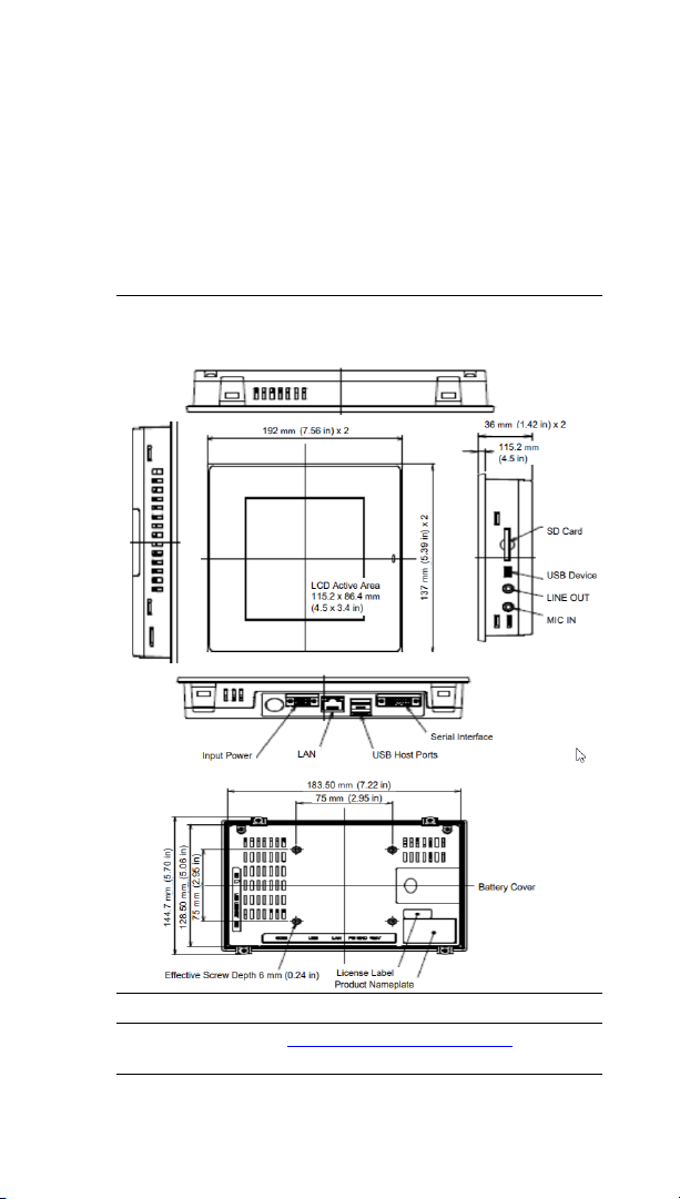
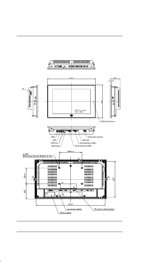
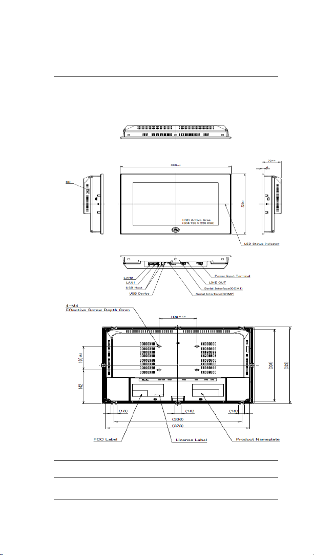
1. Physical Characteristics
The following diagrams illustrate the physical layout of
the Quick Panel+ Operator Interface, including locations
of status LEDs, communications ports, and connectors.
Figure 1.1: IC755CxS06RDx Profile and Hardware
Features
Note: Refer to the table IC755CxW06CDx Specifications for drawing
dimensions.
Quick Start Guide Section 1
GFK-2893P Sep 2019
Physical Characteristics 2
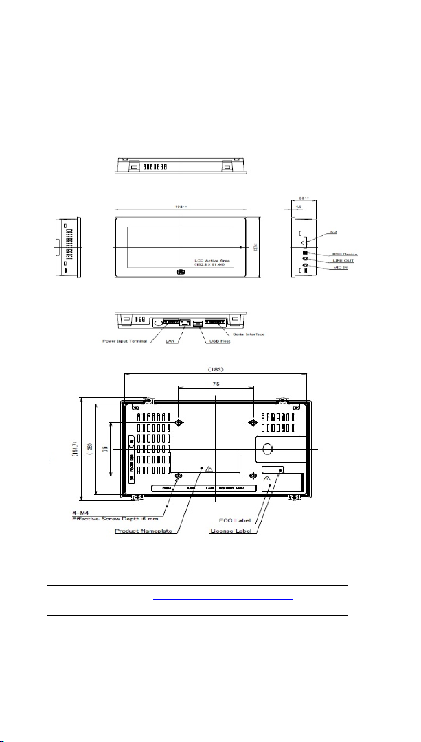
Figure 1.2: IC755CxW07CDx Profile and Hardware
Features
Note: Refer to the table IC755CxW07CDx Specifications for drawing
dimensions.
Quick Start Guide Section 1
GFK-2893P Sep 2019
Physical Characteristics 3
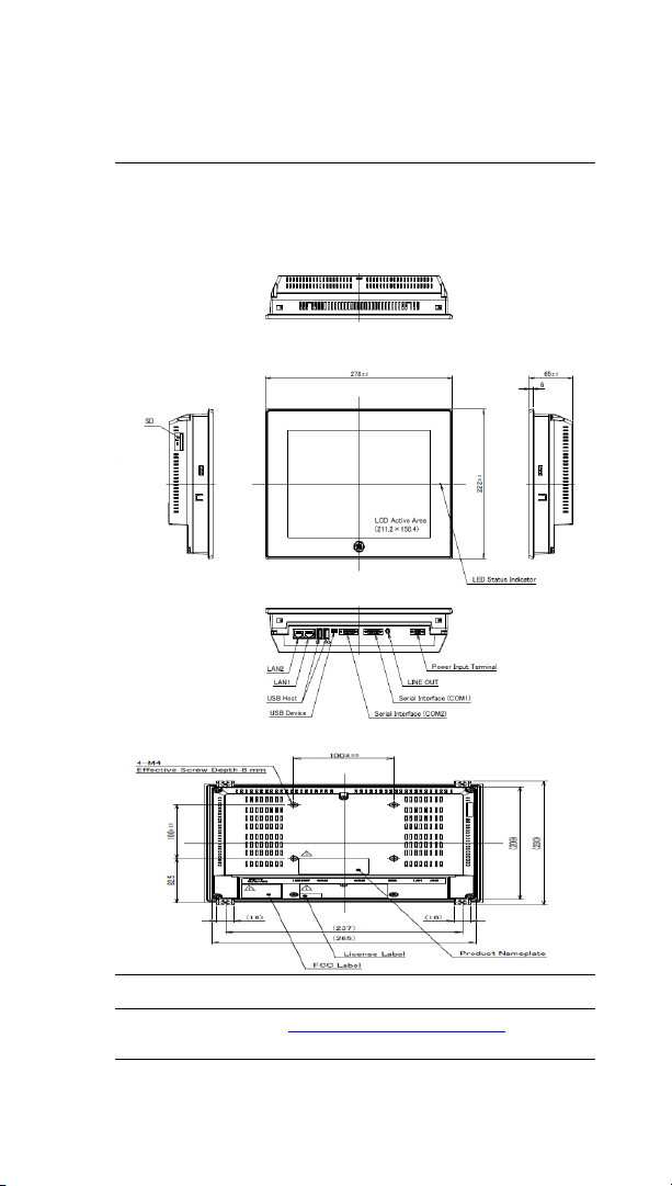
Figure 1.3: IC755CxS10CDx Profile and Hardware
Features
Note: Refer to the table IC755CxS10CDx Specifications for drawing
dimensions.
Quick Start Guide Section 1
GFK-2893P Sep 2019
Physical Characteristics 4
Figure 1.4: IC755CxS12CDx Profile and Hardware
Features
Note: Refer to the table IC755CxS12CDx Specifications for drawing
dimensions.
Quick Start Guide Section 1
GFK-2893P Sep 2019
Physical Characteristics 5
Figure 1.5: IC755CxS15CDx Profile and Hardware
Features
Note: Refer to the table IC755CxS15CDx Specifications for drawing
dimensions.
Quick Start Guide Section 2
GFK-2893P Sep 2019
Specification 7
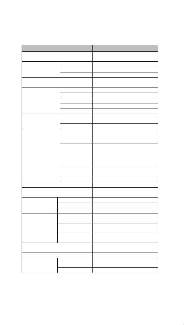
2. Specifications
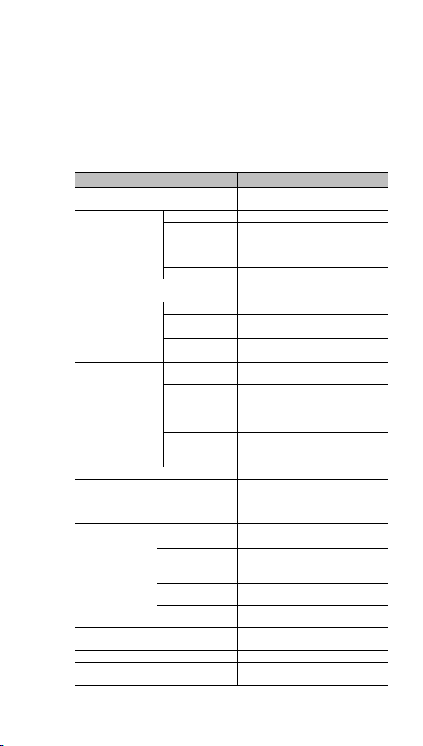
2.1 Physical Specifications and Mounting Options
IC755CxS06RDx Specifications
Item
Specification
Processor
Freescale i.MX535
(1 GHz ARM Cortex A8)
Memory
RAM
DDR3 SDRAM 512 MB
ROM
NAND FLASH 256 MB
(IC755CxS06RDx-Ax)
NAND FLASH 512 MB
(IC755CxS06RDx-Bx)
SRAM
512 KB (with battery backup)
Operating System
Microsoft Windows
Embedded Compact 7
Display
Type
5.7” TFT LCD
Resolution
320(W) x 240(H) pixels QVGA
Color
65,536
Brightness
375 cd/m2
Backlight
LED
Touchscreen
Touch Panel
Type
Analog Resistive
Multi-touch
Single-touch
Communications
Ethernet Port
1x10 Base-T / 100 Base-TX
Serial Port
1x RS-232C (COM1)
(5-pin connector)
USB, Host
2x USB 2.0 (Type-A)
Maximum power (5 V at 0.5 A)
USB, Device
1x USB 2.0 (mini Type-B)
Storage
1x SD/SDHC card slot
Audio
1x Mic In (Mono)
(3.5 mm jack),
1x Line Out (Stereo)
(3.5 mm jack)
Noise Immunity
Noise Voltage
1500 V p-p
Pulse Duration
1μs
Rise Time
1 ns
Input power
Rated Voltage
24 V dc ±20%
(3-pin connector)
Power
Consumption
15 W maximum
Frame Ground
(FG)
Frame GND connected internally to
Signal GND
Dimensions (L×W×D)
192 × 137 × 36 mm
(7.56 × 5.39 × 1.42 in)
Weight
0.7 Kg (1.54 lb)
Mounting Options
Panel Cutout
Dimensions
183.50 × 128.50 mm
(7.22 × 5.06 in)
Quick Start Guide Section 2
GFK-2893P Sep 2019
Specification 8
Item
Specification
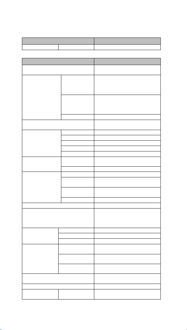
VESA Mount
75 x 75 mm (2.95 x 2.95 in)
IC755CxW07CDx Specifications
Item
Specification
Processor
Freescale i.MX535
(1 GHz ARM Cortex A8)
Memory
RAM
DDR2 SDRAM 512 MB
(IC755CxW07CDx-Ax, -Bx, -Cx)
DDR3 SDRAM 512 MB
(IC755CxW07CDx-Dx)
ROM
SLC NAND 256 MB
(IC755CxW07CDx-Ax, -Bx, -Cx)
SLC NAND 512 MB
(IC755CxW07CDx-Dx)
SRAM
512 KB (with battery backup)
Operating System
Microsoft Windows
Embedded Compact 7
Display
Type
7” Widescreen TFT LCD
Resolution
800(W) x 480(H) pixels WVGA
Color
65,536
Brightness
310 cd/m2
Backlight
LED
Touchscreen
Touch Panel
Type
Projected Capacitive
Multi-touch
Two-point
Communications
Ethernet Port
1x 10/100Base-T (RJ-45)
Serial Port
1x RS-232 UART port
(5-pin connector)
USB, Host
2x USB 2.0 (Type-A)
Maximum power (5 V at 0.5 A)
USB, Device
1x USB 2.0 (mini Type-B)
Storage
1x SD/SDHC card slot
Audio
1x Mic In (Mono)
(3.5 mm jack),
1x Line Out (Stereo)
(3.5 mm jack)
Noise Immunity
Noise Voltage
1500 V p-p
Pulse Duration
1μs
Rise Time
1 ns
Input power
Rated Voltage
24 V dc ±20%
(3-pin connector)
Power
Consumption
15 W maximum, 0.625 A
Frame Ground
(FG)
Frame GND connected internally to
Signal GND
Dimensions (L×W×D)
192 × 137 × 36 mm
(7.56 × 5.39 × 1.42 in)
Weight
0.80 Kg (1.76 lb)
Mounting Options
Panel Cutout
Dimensions
183.50 × 128.50 mm
(7.22 × 5.06 in)
Quick Start Guide Section 2
GFK-2893P Sep 2019
Specification 9
Item
Specification
VESA Mount
75 x 75 mm (2.95 x 2.95 in)
IC755CxS10CDx Specifications
Item
Specification
Processor
Freescale i.MX535
(1 GHz ARM Cortex A8)
Memory
RAM
DDR3 SDRAM 1 GB
ROM
SLC NAND 512 MB
SRAM
512 KB (with battery backup)
Operating System
Microsoft Windows
Embedded Compact 7
Display
Type
10.4” Standard TFT LCD
Resolution
800(W) x 600(H) pixels SVGA
Color
65,536
Brightness
400 cd/m2
Backlight
LED
Touchscreen
Touch Panel
Type
Projected Capacitive
Multi-touch
Two-point
Communications
Ethernet Port
2x 10/100Base-T (RJ-45)
Serial Port
1x RS-232 UART port
1x RS-232/485 port
(2x 5-pin connector)
USB, Host
2x USB 2.0 (Type-A)
Maximum power (5 V at 0.5 A)
USB, Device
1x USB 2.0 (mini Type-B)
Storage
1x SD/SDHC card slot
Audio
1x Line Out (Stereo)
(3.5 mm jack)
Noise Immunity
Noise Voltage
1500 V p-p
Pulse Duration
1 μs
Rise Time
1 ns
Input power
Rated Voltage
12/24 V dc ±20%
(3-pin connector)
Power
Consumption
18 W maximum, 1.5 / 0.75 A
Frame Ground
(FG)
Frame GND connected internally to
Signal GND
Dimensions (L×W×D)
278 × 222 × 65 mm
(10.95 × 8.74 × 2.56 in)
Weight
2.40 kg (5.29 lbs)
Mounting Options
Panel Cutout
Dimensions
266 × 210 mm (10.47 × 8.27 in)
VESA Mount
100 x 100 mm (3.94 x 3.94 in)
Quick Start Guide Section 2
GFK-2893P Sep 2019
Specification 10
IC755CxS12CDx Specifications
Item
Specification
Processor
Freescale i.MX535
(1 GHz ARM Cortex A8)
Memory
RAM
DDR3 SDRAM 1 GB
ROM
SLC NAND 512 MB
SRAM
512 KB (with battery backup)
Operating System
Microsoft Windows
Embedded Compact 7
Display
Type
12.1” Standard TFT LCD
Resolution
800(W) x 600(H) pixels SVGA
Color
65,536
Brightness
450 cd/m2
Backlight
LED
Touchscreen
Touch Panel
Type
Projected Capacitive
Multi-touch
Two-point
Communications
Ethernet Port
2x 10/100Base-T (RJ-45)
1x 10/100Base-T (RJ-45) for
IC755CxS12CDA
Serial Port
1x RS-232 UART port
1x RS-232/485 port
(2x 5-pin connector)
(1x 10-pin connector for
IC755CxS12CDA)
USB, Host
2x USB 2.0 (Type-A
Maximum power (5 V at 0.5 A)
USB, Device
1x USB 2.0 (mini Type-B)
Storage
1x SD/SDHC card slot
Audio
1x Line Out (Stereo)
(3.5 mm jack)
Noise Immunity
Noise Voltage
1500 V p-p
Pulse Duration
1 μs
Rise Time
1 ns
Input power
Rated Voltage
12/24 V dc ±20%
(3-pin connector)
Power
Consumption
30 W maximum, 2.5 / 1.25 A
Frame Ground
(FG)
Frame GND connected internally to
Signal GND
Dimensions (L×W×D)
314 × 248 × 65 mm
(12.36 × 9.76 × 2.56 in)
Weight
3 kg (6.61 lbs)
Mounting Options
Panel Cutout
Dimensions
302 × 228 mm (11.89 × 8.98 in)
VESA Mount
100 x 100 mm (3.94 x 3.94 in)

Quick Start Guide Section 2
GFK-2893P Sep 2019
Specification 11
IC755CxS15CDx Specifications
Item
Specification
Processor
Freescale i.MX535
(1 GHz ARM Cortex A8)
Memory
RAM
DDR3 SDRAM 1 GB
ROM
SLC NAND 512 MB
SRAM
512 KB (with battery backup)
Operating System
Microsoft Windows
Embedded Compact 7
Display
Type
15” Standard TFT LCD
Resolution
1024(W) x 768(H) pixels XGA
Color
65,536
Brightness
310 cd/m2
Backlight
LED
Touchscreen
Touch Panel
Type
Projected Capacitive
Multi-touch
Two-point
Communications
Ethernet Port
2x 10/100Base-T (RJ-45)
Serial Port
1x RS-232 UART port
1x RS-232/485 port
(2x 5-pin connector)
USB, Host
2x USB 2.0 (Type-A
Maximum power (5 V at 0.5 A)
USB, Device
1x USB 2.0 (mini Type-B)
Storage
1x SD/SDHC card slot
Audio
1x Line Out (Stereo)
(3.5 mm jack)
Noise Immunity
Noise Voltage
1500 V p-p
Pulse Duration
1 μs
Rise Time
1 ns
Input power
Rated Voltage
12/24 V dc ±20%
(3-pin connector)
Power
Consumption
30 W maximum, 2.5 / 1.25 A
Frame Ground
(FG)
Frame GND connected internally to
Signal GND
Dimensions (L×W×D)
399 × 323 × 70 mm
(15.71 × 12.72 × 2.76 in)
Weight
4.46 kg (9.83 lbs)
Mounting Options
Panel Cutout
Dimensions
379 × 305 mm
(14.92 × 12.01 in)
VESA Mount
100 x 100 mm (3.94 x 3.94 in)
Quick Start Guide Section 2
GFK-2893P Sep 2019
Specification 12
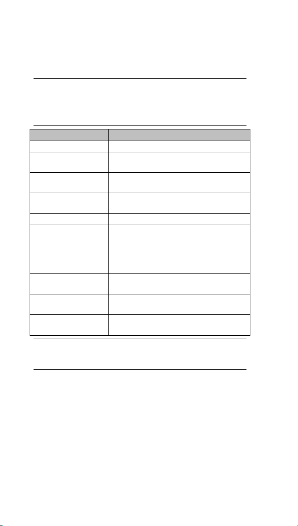
2.2 Environmental Specifications
Note: Install the Quick Panel+ in a well-ventilated location that
is not exposed to dust, corrosive gases or liquids, rain,
strong ultra-violet light or direct sunlight, and meets the
following specifications.
Item
Specification (All Display Units)
Cooling
Natural convection
Ambient Operating
Temperature
0 to +55°C (32 to 131 °F)
Ambient Storage
Temperature
-10 to +60°C (14 to 140 °F)
Ambient Humidity
(Operating/Storage)
85% RH Non-condensing, wet-bulb
temperature: 30°C (86 °F) or less
Environment
Pollution Degree 2, Indoor use only
Vibration Resistance
5 to 9 Hz single-amplitude 3.5 mm
9 to 150 Hz constant-accelerated
velocity 9.8 m/s2 ; X, Y, Z directions 10
time (100 minutes)
(Compliance IEC61181-2, JIS B 3502)
Altitude
800~1114 hPa, altitude up to 2000 m
(6561.68 ft)
RoHS
Compliant with EU RoHS Directive
2011/65/EU
Enclosure Rating
UL Type 4X;
IP65 in panel mount only
Note: For additional product standards and agency approvals,
refer the section Product Certifications and Installation
Guidelines.

Quick Start Guide Section 3
GFK-2893P Sep 2019
Initial Startup 13
3. Initial Startup
Note: For installation requirements, complete installation
procedures, and operating information, refer to the
QuickPanel+ Operator Interface User Manual (GFK-
2847).
You will need the following:
▪ A Safety Extra Low Voltage (SELV) and Limited
Energy Circuit or SELV and Class 2 dc power supply.
▪ The power terminal block is supplied with the
product. For voltage and requirements, refer to the
Input Power specifications in the table, General
Specifications.
▪ The mating power terminal block supports
stranded 30 to 14 AWG (0.05 to 2.00 mm2) wires.
The user calculates proper gauge wiring for current
carrying capacity and loss according to local
regulations.
▪ At a minimum, the cable must be rated for 75°C
(167 °F) or more.
WARNING
ELECTRICAL SHOCK HAZARD - To avoid personal injury or
damage to equipment, ensure that the dc supply is
disconnected from power and the leads are not energized
before attaching them to the unit's power supply plug.

Quick Start Guide Section 3
GFK-2893P Sep 2019
Initial Startup 14
3.1 Quick Panel+ Battery Installation
CAUTION
• Installing the battery should only be performed by
trained personnel and in a non-hazardous
location.
• If the QuickPanel
+
is VESA mounted, detach from
the VESA arm when replacing the battery. Refer to
the section, Mounting on a VESA arm.
• The battery should only be installed when the unit
is powered off.
• Care should be taken to protect and insert the
battery with correct polarity.
• Do not use any metallic item to remove the
battery (such as screwdrivers, knives, pliers, and
so forth).
• Be careful to not drop the battery or any
associated screws into the unit.
• Be careful of edges on internal sides of the
enclosure and frame.
➢ To install the battery
1. Remove the battery cover by pressing down
while sliding outward.
Figure 3.1: IC755CxS06RDx/ IC755CxW07CDx Battery
Cover Removal

Quick Start Guide Section 3
GFK-2893P Sep 2019
Initial Startup 15
2. Connect the battery harness connector to the
header, noting keyed orientation.
Figure 3.2: IC755CxS06RDx /IC755CxW07CDx
Battery Harness Connection
Batter y Part Numbe r
IC755ACCBATT
3. Verify that positive (red) is down and negative
(black) is up.
4. Wrap the harness connector around to match
the following figure. Do not let the harness
connector go above the tab.
Figure 3.3: Harness Connector Orientation
5. Slide the battery cover into place, taking
care not to pinch the harness connector.

Quick Start Guide Section 3
GFK-2893P Sep 2019
Initial Startup 16
3.2 Battery Replacement
WARNING
• Batteries may present a risk of fire, explosion, or
chemical burn if mistreated. Do not crush, disassemble,
short-circuit, or dispose of in fire.
• Use of batteries not specified for use with the Quick
Panel+ product may present a risk of fire or explosion.
Caution
• Replace the battery for the IC755CxS06RDx only
with Emerson battery part number
IC755ACCBATT.
• Replace the battery for the IC755CxW07CDx only
with Emerson battery part number
IC755ACCBATT.
• Replace the battery for the IC755CxSxxCDx only
with Emerson battery part number
IC755ACCBATTNL.
3.3 Connecting Input Power
➢ To connect input power
1. Verify that the power cable is not energized.
2. Loosen the
screw clamps
on the mating
power
connector.
3. Strip the
insulation from
the power
cables.
M2.5
Mounting clamps
M2
Screw clamps
Power Connector
FG
GND +24 V dc

Quick Start Guide Section 3
GFK-2893P Sep 2019
Initial Startup 17
4. Secure the power cable to the mating
connector, noting polarity, and tighten the
screw clamps. The torque for the attaching
screws is 0.3 Nm (2.26 in-lb).
5. Apply dc power to the unit. During normal
startup and operation, the Quick Panel+ status
LED indicator displays as follows:
• Solid amber while the Quick Panel
+
unit is
starting up
• Solid green during normal operation
6. Once power is applied, the Quick Panel
+
begins
initializing. The first thing to display is the
splash screen.
➢ To skip running any programs included in the
Startup folder, tap Don’t run Startup programs.
The Microsoft Windows Embedded Compact 7
operating system starts automatically.
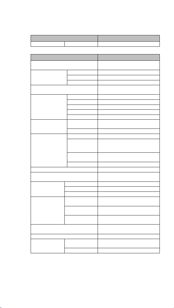
3.4 LED Indicators
3.4.1 Operation Status LEDs
The Quick Panel+ has one tri-color LED that provides
visual operation status indication for the
IC755CxS06RDx, IC755CxW07CDx, and
IC755CxSxxCDx units.
LED State
Quick Panel+ State
Amber, solid
Operating system starting
Green, solid
Normal operating state
Green, blinking
Backlight off
Red, blinking
Backlight failure
Off
Power not applied to unit

Quick Start Guide Section 3
GFK-2893P Sep 2019
Initial Startup 18
3.4.2 Ethernet Port Operation LEDs
The Ethernet port has two LED indicators: Speed and
Link Activity.
Speed
Link Activity
LED
LED State
Operating
State
Speed
Yellow, on
10/100
Link
Activity
Green, on
Link status

Quick Start Guide Section 4
GFK-2893P Sep 2019
Mounting & Installation 19
4. Mounting and Installation
4.1 Protective Sheet Installation
➢ To install the protective sheet
1. Remove the protective film from the
QuickPanel+ display screen.
2. Wipe the display unit of any dust or fingerprints.
3. Peel back a corner of the clear side of the
protective sheet.
4. Begin applying the corner to the display screen.
5. Slowly apply the rest of the protective sheet,
smoothing out as you go.
6. Peel the green curing film from the protective
sheet.
4.2 Mounting Location
When mounting the Quick Panel
+
Operator Interface,
make sure the mounting area allows room to insert and
remove the SD card, cables, and mounting brackets.
Select a location that allows natural convection air flow
from bottom to top of the Quick Panel+ enclosure. Do not
mount the Quick Panel+ at an angle more than 30° from
the vertical, as illustrated in the following figure. Refer to
the section, Environmental Specifications.

Quick Start Guide Section 4
GFK-2893P Sep 2019
Mounting & Installation 20
Figure 4.1: Mounting Angle
4.3 Panel Mounting
To mount the Quick Panel+ in an enclosure, you will need
the following equipment:
• One #2 Phillips head screwdriver
• Mounting brackets (supplied)
The mounting holes for the IC755CxS06RDx,
IC755CxW07CDx, and IC755CxS10CDx are located on
the top and bottom sides of the unit.
Figure 4.2: IC755CxS06RDx Mounting Holes

Quick Start Guide Section 4
GFK-2893P Sep 2019
Mounting & Installation 21
Figure 4.3: IC755CxW07CDx Mounting Holes
Figure 4.4: IC755CxS10CDx Mounting Holes
The IC755CxS12CDx and IC755CxS15CDx mounting
holes are located on the top, bottom, and sides of the
unit.

Quick Start Guide Section 4
GFK-2893P Sep 2019
Mounting & Installation 22
Figure 4.5: IC755CxS12CDx Mounting Holes
Figure 4.6: IC755CxS15CDx Mounting Holes
4.4 Mounting and Installation Procedure
CAUTION
• When installing the Quick Panel
+
into the panel, pay
careful attention while handling the unit so it does
not drop and damage the unit.
➢ To install the Quick Panel
+
1. Cut an opening in the panel according to the
specifications in the following figures.

Quick Start Guide Section 4
GFK-2893P Sep 2019
Mounting & Installation 23
Note: Panel cutout tolerances are +0.50, -0.00 mm (+0.02, -
0.00 in).
Figure 4.7: IC755CxS06RDx Panel Cutout Dimensions
Panel Thickness:
1.0 to 5.0 mm
(0.04 to 0.20 in)
128.50 mm (5.06 in)
183.50 mm (7.22 in)
Figure 4.8: IC755CxW07CDx Panel Cutout Dimensions
Panel Thickness:
1.0 to 5.0 mm
(0.04 to 0.20 in)
128.50 mm (5.06 in)
183.50 mm (7.22 in)
Figure 4.9: IC755CxS10CDx Panel Cutout Dimensions
Panel Thickness:
1.6 to 5.0 mm
(0.06 to 0.20 in)
266 mm (10.47 in)
210 mm (8.27 in)

Quick Start Guide Section 4
GFK-2893P Sep 2019
Mounting & Installation 24
Figure 4.10: IC755CxS12CDx Panel Cutout Dimensions
Panel Thickness:
1.6 to 5.0 mm
(0.06 to 0.20 in)
228 mm (8.98 in)
302 mm (11.89 in)
Figure 4.11: IC755CxS15CDx Panel Cutout Dimensions
Panel Thickness:
1.6 to 5.0 mm
(0.06 to 0.20 in)
379 mm (14.92 in)
305 mm (12.01 in)
2. Verify that the gasket is present and properly
seated in the bezel channel located on the sides of
the unit.
3. Insert the Quick Panel
+
into the mounting panel
cutout.
Figure 4.12: Cutout for Quick Panel

Quick Start Guide Section 4
GFK-2893P Sep 2019
Mounting & Installation 25
4. Insert the hook of the mounting bracket into the
mounting hole as displayed in the following figure.
Figure 4.13: Hook of Mounting Bracket
5. Tighten the screws on the mounting bracket
in a clock-wise direction.
Figure 4.14: Mounting bracket screw turning
Torque Range for Mounting Clamp Screws
Display Unit
Torque Range
IC755CxS06RDx
0.3 Nm (2.66 in-lb)
IC755CxW07CDx
0.3 Nm (2.66 in-lb)
IC755CxS10CDx
0.7 Nm (6 in-lb)
IC755CxS12CDx
1.0 to 1.2 Nm (8.5 to 10.6 in-lb)
IC755CxS15CDx
1.0 to 1.2 Nm (8.5 to 10.6 in-lb)

Quick Start Guide Section 4
GFK-2893P Sep 2019
Mounting & Installation 26
4.5 VESA Arm Mounting
The Quick Panel+ can be installed on a commercially
available Video Electronics Standards Association (VESA)
MIS-D arm, stand, or apparatus that complies with the
UL1678 standard.
➢ To VESA mount the Quick Panel
+
unit:
use the mounting holes located on the back of
the unit (displayed in the following figures).
The mounting holes for IC755CxS06RDx and
IC755CxW07CDx attach with M4 screws that
are 6 mm (0.24 in) or less in length.
The mounting holes for IC755CxSxxCDx mounting
holes attach with M4 screws that are 8 mm (0.32
in) or less in length.
Torque Range for Mounting M4 Screws
Display Unit
Torque Range
IC755CxS06RDx
0.7 to 0.8 Nm (6.2 to 7.1 in-lb)
IC755CxW07CDx
0.7 to 0.8 Nm (6.2 to 7.1 in-lb)
IC755CxSxxCDx
1.0 to 1.2 Nm (8.9 to 10.6 in-lb)

Quick Start Guide Section 4
GFK-2893P Sep 2019
Mounting & Installation 27
Figure 4.15: IC755CxW07CDx/IC755CxS06RDx VESA
Mounting Holes
75
mm
75
mm
75 mm
(2.95 in)
75 mm
(2.95 in)
Figure 4.16: IC755CxSxxCDx VESA Mounting Holes
100 mm
100 mm
100 mm
(3.94 in)
100 mm
(3.94 in)
Note: For user manuals, product updates, and other
information, go to the Support website,
https://www.emerson.com/Industrial-AutomationControls/support and refer to Operator Interfaces and
PC.

Quick Start Guide Section 4
GFK-2893P Sep 2019
Mounting & Installation 28
4.6 Connectors
4.6.1 Power Connector Details
Pin #
Signal Name
Pin-out
1
+24 V dc†
2
GND 3 FG
†
IC755CxSxxCDA supports both +12 V dc or +24 V dc IN
4.6.2 Ethernet Port Details
Interface: Ethernet 10BASE-T/100BASE-TX
Pin #
Signal Name
Pin-out
1
TX+
2
TX- 3 RX+ 4 NC 5 NC 6 RX- 7 NC 8 NC
4.6.3 USB Host Port Details
Interface: 2x USB 2.0
Pin #
Signal Name
Pin-out
1
USB_VCC
5.
2
USB_D-
3
USB_D+
4
USB_GND

Quick Start Guide Section 4
GFK-2893P Sep 2019
Mounting & Installation 29
4.6.4 Serial Port Details
4.6.4.1 IC755CxS06RDx
4.6.4.1.1 Serial Port COM1
Interface: RS-232
Pin #
Signal Name
1
TXD 2 RXD 3 RTS 4 CTS
5
SGND
Figure 4.2: IC755CxS06RDx Serial Port COM1 Pin-out
IC755CxW07CDx
Interface: x1 RS-232
Pin#
Signal Name
1
TXD 2 RXD 3 RTS
4
CTS
5
SGND

Quick Start Guide Section 4
GFK-2893P Sep 2019
Mounting & Installation 30
Figure 4.3: IC755CxW07CDx Serial Port COM1 Pin-out
Pin 1
Pin 5
1 2 3 4 5
4.6.4.3 IC755CxSxxCDx
4.6.4.3.1 Serial Port COM1
Interface: RS-232
Pin #
Signal Name
1
TXD
2
RXD 3 RTS 4 CTS
5
SGND
Figure 4.4: C755CxSxxCDx Serial Port COM1 Pin-out

Quick Start Guide Section 4
GFK-2893P Sep 2019
Mounting & Installation 31
4.6.4.3.2 Serial Port COM2
Interface: RS-232C/485 (default is
RS-485 Half-duplex)
Pin #
RS-232
RS-485
Signal
Name
Signal Name
(Full-
duplex†)
Signal Name
(Half-
duplex†)
1
TXD
TXD+
DATA+‡
2
RXD
TXD-
DATA-‡
3
RTS
RXD+
DATA+‡
4
CTS
RXD-
DATA-‡
5
SGND
SG
SG
†
Full-duplex RS–485 is backwards compatible to
RS–422 mode.
‡
Pins 1-3 and 2-4 are connected internally.
Figure 4.5: C755CxSxxCDx Serial Port COM2 Pin-out

Quick Start Guide Section 5
GFK-2893P Aug 2019
Product Certification & Installation Guidelines 33
5. Product Certifications and Installation Guidelines for Conformance
The Quick Panel+ Operator Interface is intended for use
in industrial environments and, when properly installed,
shall comply with the following agency approvals.
5.1 Agency Approvals
Note: The agency approvals listed in the following table and on
the Declaration of Conformities are believed to be accurate.
However, the product’s agency approvals should be verified by
the marking on the unit itself.
Description
Agency
Marking
Comments
N.A. Safety for
Programmable
Controller for use
in Hazardous
locations
Class I Division 2
Groups A, B, C, D
(applicable to
7'',10'',12'', 15''
Display units)
Class I Division 2
Groups A, B, C, D;
Class 2 Division 2
Groups F, G; Class
3 Division 1 and
Division 2
(applicable only to
6'' Display unit)
Certification by
Underwriter's
Laboratories (UL) to
UL 61010-1;
UL 61010-2-201;
CSA C22.2 No 142–
1987; CSA 61010-1;
CSA 61010-2-201
ISA 12.12.01 standard
and CSA C22.2 No
213-M1987

Quick Start Guide Section 5
GFK-2893P Sep 2019
Product Certification & Installation Guidelines 34
Description
Agency
Marking
Comments
Explosive
Atmospheres
Directive
European Safety
for Hazardous
Areas
Equipment Group
II, Category 3, Gas
Groups IIC, Dust
Group IIIC
Certification in
accordance with the
ATEX Directive
14/34/EU with an
Independent 3rd
Party Assessment
Certificate only
applies to the 12” and
15” Display units: EN
60079-0/A11,
EN 60079-15, and
EN 60079-31;
Part numbers:
IC755CSW07CDACA,
IC755CSS10CDACA,
IC755CSS12CDBCA,
IC755CSS15CDACA
Electromagnetic
Compatibility
Directive
European
Electromagnetic
Compatibility
(EMC) for
Industrial Control
Equipment
Self-declaration in
accordance with
European Directives
EN61000-6-2,
EN61000-6-4
Maritime Society
Certification
Product
not
marked,
verified
by
certificat
e
American Bureau of
Shipping (ABS),
Det Nortske Veritas
/Germanischer Lloyds
(DNV-GL), and Bureau
Veritas (BV)
certification on
conformal coated 6,

Quick Start Guide Section 5
GFK-2893P Sep 2019
Product Certification & Installation Guidelines 35
Description
Agency
Marking
Comments
7, 10, 12, 15” units
only.
5.2 Conditions of Safe Use for Installation in Hazardous Locations
The following information applies to products bearing
the UL marking for Hazardous areas and the ATEX
marking for Zone 2 explosive atmospheres:
• Suitable for use in Class I Division 2 Groups A, B, C,
D; Class 2 Division 2 Groups F, G; Class 3 Division 1
and Division 2.
• Suitable for Group II, Category 3, Gas Groups IIC,
Dust Group IIIC (applicable only to the
IC755CSW07CDACA, IC755CSS10CDACA,
IC755CSS12CDBCA, and IC755CSS15CDACA Display
units):
1. The equipment shall only be used in an area of at
least pollution degree 2, as defined in IEC 60664-1.
Note: Pollution degree 2 can be achieved when the
installation is in a controlled environment with suitably
controlled condensation or airborne pollution.
2. The equipment shall be installed in an enclosure
that provides a minimum ingress protection of IP
54 in accordance with IEC 60079-0.

Quick Start Guide Section 5
GFK-2893P Sep 2019
Product Certification & Installation Guidelines 36
3. Transient protection shall be provided that is set
at a level not exceeding 140% of the peak rated
voltage value at the supply terminals to the
equipment.
• USB retaining clamp for IC755CxS12CDBCA and
IC755CxS15CDACA must be used in hazardous
location installations as follows:
1. Connect the USB cable.
Figure 5.1: USB cable
2. Insert the retaining clamp in the port
above the USB connector.
Figure 5.2: USB Retaining
Clamp
3. Adjust the position of the retaining clamp
by pushing the lever of the retaining

Quick Start Guide Section 5
GFK-2893P Sep 2019
Product Certification & Installation Guidelines 37
clamp. Then close the retaining clamp to
fit the cable size.
Figure 5.3: Adjusting position of retaining
clamp
• USB retaining clamp for IC755CSW07CDACA
must be used in hazardous location
installations as follows:
1. Connect the USB retaining clamp plate.
Figure 5.4: USB retaining Clamp Plate
2. Connect the USB cable and insert the
retaining clamp into the retaining clamp
plate.

Quick Start Guide Section 5
GFK-2893P Sep 2019
Product Certification & Installation Guidelines 38
Figure 5.5: USB cable retaining clamp
3. Adjust the position of the retaining clamp
by pushing the lever of the retaining
clamp. Then close the retaining clamp to
fit the cable size.
Figure 5.6: Inserting retaining clamp

Quick Start Guide Section 5
GFK-2893P Sep 2019
Product Certification & Installation Guidelines 39
WARNING
• EXPLOSION HAZARD - Do not connect or
disconnect equipment power, communication,
audio, or battery unless power has been removed
or the area is known to be non-hazardous.
• EXPLOSION HAZARD - Substitution of components
may impair suitability.
• EXPLOSION HAZARD -Do not VESA-Mount.
Panel-mount only with enclosures that shall only be
opened with the use of a tool in an area where the
risk of impact is low.
• Do not make any connections to the mini-USB/mic
terminal as it will invalidate the ATEX approval.
5.3 Government Regulations
The FCC requires the following note to be published
according to FCC guidelines:
Note: This equipment has been tested and found to comply
with the limits for a Class A digital device, pursuant to
Part 15 of the FCC Rules. These limits are designed to
provide reasonable protection against harmful
interference when the equipment is operated in a
commercial environment. This equipment generates,
uses, and can radiate radio frequency energy and, if not
installed and used in accordance with the instruction
manual, may cause harmful interference to radio
communications. Operation of this equipment in a
residential area is likely to cause harmful interference in
which case the user is required to correct the
interference at their own expense.
Changes or modifications to this unit that are not
expressly approved by Emerson could void the user’s
authority to operate the equipment.

Quick Start Guide Section 5
GFK-2893P Sep 2019
Product Certification & Installation Guidelines 40
Industry Canada requires the following note to be
published:
Note: This Class A digital apparatus complies with Canadian
CAN ICES-3 (A)/NMB-3 (A).
5.4 EMC Installation and Operation Considerations
This equipment is intended for industrial use only and
complies with a minimum level of EMC performance as
defined by EN 61000-6-2 and EN 61000-6-4 standards.
To meet these requirements, the following installation
and operation considerations to be considered:
• Shielding USB cables
• Limiting RS-232 cables to 15 m (49.2 ft) in
length
• Using Audio ports only during operational
maintenance
Although these considerations were deliberated during
testing, actual EMC environments vary greatly.
Therefore, these considerations may not be necessary.
Likewise, additional measures, such as filtering, wire
separation, and cable routing, may need to be
considered to ensure intended operation of the overall
system.


QUICK START GUIDE
GFK-2893P
Sep2019
Technical Support & Contact Information:
Home link: http://www.Emerson.com/Industrial-Automation-
Controls
Knowledge Base: https://www.emerson.com/Industrial-
Automation-Controls/support
Note: If the product is purchased through an Authorized
Channel Partner, please contact the seller directly for any
support.
Emerson reserves the right to modify or improve the designs or
specifications of the products mentioned in this manual at any
time without notice. Emerson does not assume responsibility
for the selection, use or maintenance of any product.
Responsibility for proper selection, use and maintenance of any
Emerson product remains solely with the purchaser.
© 2019 Emerson. All rights reserved.
Emerson Terms and Conditions of Sale are available upon
request. The Emerson logo is a trademark and service mark of
Emerson Electric Co. All other marks are the property of their
respective owners.
 Loading...