

Page 1
Important Product Information PACSystems* RX3i
IC695PNS001-BBBC IC695PNS101-AAAA
IC695PNS001CA-BBBC IC695PNS101CA-AAAA
GFK-2738Q RX3i PROFINET Scanner RX3i Advanced PROFINET Scanner
August 2018
The PACSystems* IC695PNS001 RX3i PROFINET Scanner and IC695PNS101 RX3i Advanced
PROFINET Scanner modules connect a remote universal RX3i I/O rack of Series 90-30 or
RX3i modules to a PROFINET I/O Controller. The PROFINET Scanner scans the modules in
its rack, retrieving input data and providing output data, and exchanges that data on the
PROFINET I/O LAN at the configured production rate.
The PNS manages PROFINET communication and module configuration between an I/O
Controller and modules in the remote rack. If network communications are lost, the PNS
manages I/O states according to the individual module configurations.
The PNS001 and PNS101 support 10/100/1000 Mbps Copper, 100/1000 Mbps Multimode Fiber, and 100/1000 Mbps Single-mode Fiber. PROFINET communications on the
network require 100 or 1000 Mbps link speed. Although 10 Mbps cannot be used for
PROFINET communications, 10 Mbps can be used for other types of Ethernet traffic such
as PING.
Features of the RX3i PNS001 PROFINET Scanner include:
▪ Configuration services for all supported Series 90-30 and RX3i I/O Modules using
Proficy* Machine Edition (PME). For a list of currently supported I/O modules, refer
to Supported Modules, Power Supplies and Backplanes.
▪ Support for daisy-chain/line, star, or ring (PROFINET Media Redundancy Protocol
(MRP)) topologies.
▪ Four switched Ethernet ports - two 8-conductor RJ-45 shielded twisted pair
10/100/1000 Mbps copper interfaces and two Small Form-factor Pluggable (SFP)
cages for user-supplied SFP devices.
▪ The network can include media interfaces of more than one type.
▪ Support for transfer of I/O Device Name to another PNS module using an SD card.
This eliminates the need to connect a configuration tool, such as Proficy Machine
Edition when replacing a module.
▪ A front panel Ethernet RJ-45 port for field firmware updates.
The RX3i PNS101 Advanced PROFINET Scanner includes all features of the
PNS001 PROFINET Scanner and adds:
▪ Support for Sequence of Events recording with IRIG-B time synchronization of events
accurate to 1ms. The PNS101 buffers up to 4000 events from up to four
IC694MDL660 32 Circuit Discrete Input modules at a maximum rate of 400 events
per second. Unmodulated IRIG B time signals are decoded using either an
IC695HSC304 or IC695HSC308 High Speed Counter Module. The PNS101 may also be
used as a standard PROFINET scanner when Sequence of Events is disabled.
*
Indicates a trademark of General Electric Company and/or its subsidiaries. All other trademarks are the property of their respective
owners.
© 2013-2018 General Electric Company. All Rights Reserved.
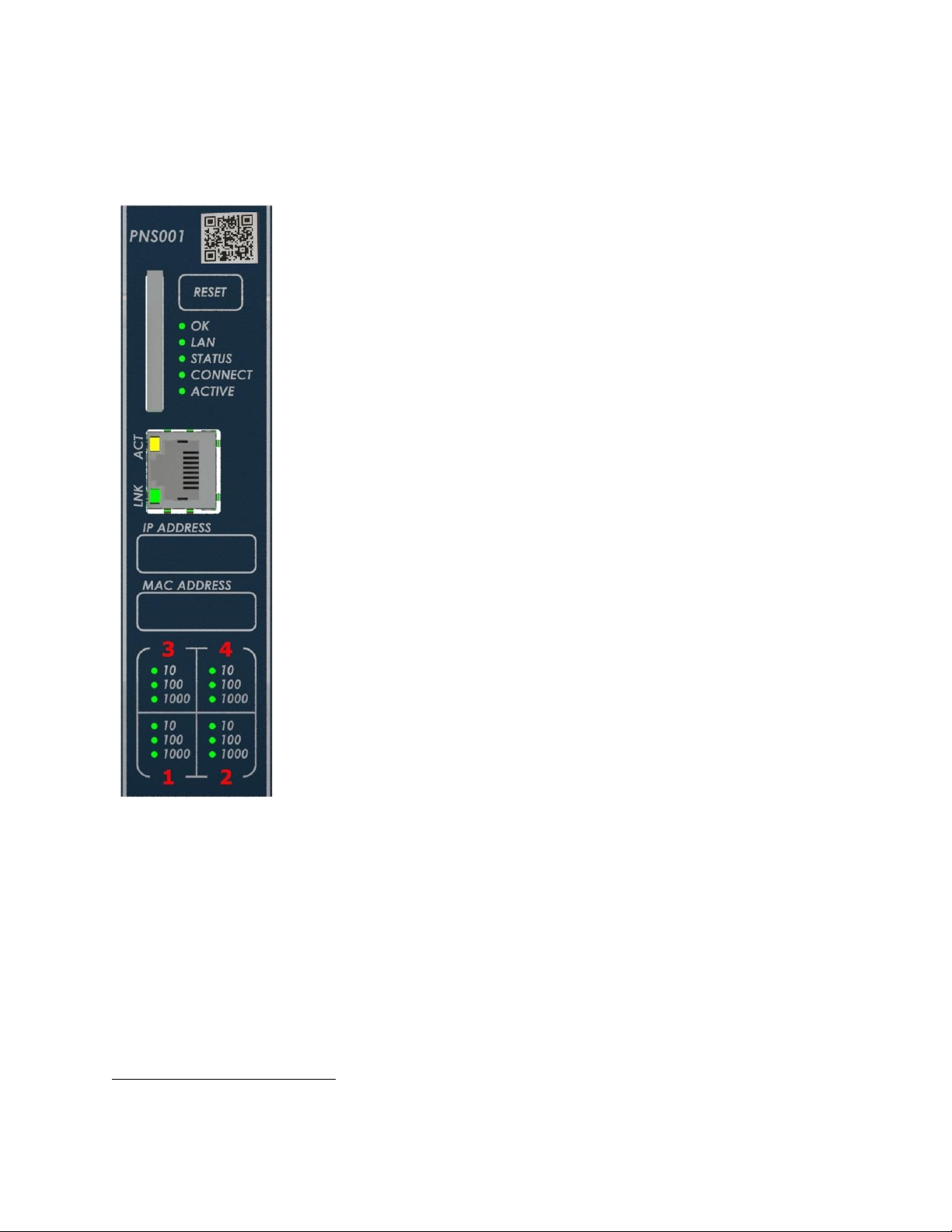
The PNS001 & PNS101
share the same front
panel markings except
for the catalog
number and QR code.
Page 2

2 RX3i PROFINET Scanner & Advanced PROFINET Scanner
GFK-2738Q IC695PNS001-BBBC & IC695PNS101-AAAA
Ordering Information
IC695PNS001
PACSystems RX3i PROFINET Scanner Module 10/100/1000 with four Ports
(two SFP connections, two RJ45 connections)
Includes a blank SD card
IC695PNS001CA
Conformal Coated PACSystems RX3i PROFINET Scanner Module 10/100/1000 with four Ports
(two SFP connections, two RJ45 connections)
Includes a blank SD card
IC695PNS101
PACSystems RX3i Advanced PROFINET Scanner Module 10/100/1000 with four Ports
(two SFP connections, two RJ45 connections)
Includes a blank SD card
IC695PNS101CA
Conformal Coated PACSystems RX3i Advanced PROFINET Scanner Module 10/100/1000 with four Ports
(two SFP connections, two RJ45 connections)
Includes a blank SD card
IC695SPC100
RX3i 10/100/1000Base-T copper SFP
IC695SPF002
RX3i 100Base-FX (fiber 2 km) SFP (Multi-mode fiber - MMF)
IC695SPF550
RX3i 1000Base-SX (fiber 550 m) SFP (MMF)
IC695SPF010
RX3i 1000Base-LX (fiber 10 km) SFP (Single-mode fiber - SMF)
Page 3

RX3i PROFINET Scanner & Advanced PROFINET Scanner 3
IC695PNS001-BBBC & IC695PNS101-AAAA GFK-2738Q
Specifications
PROFINET Support
PROFINET Version 2.3 Class A I/O Device
Redundantly controlled operation implements PROFINET V2.3 Type S-2 System Redundancy
Proficy Machine Edition
Version Required
PNS001 & PNS101: Version 8.50 SIM 2 or later
Power Requirements
PNS001-Bxxx or later:
PNS101-Axxx or later:
3.3 Vdc
0.6 A with no SFP devices installed
1.3 A maximum (two SFP devices installed,
0.35A per SFP)
PNS001-Axxx:
3.3 Vdc
1.2 A with no SFP devices installed
1.9 A maximum (two SFP devices installed,
0.35A per SFP)
PNS001-Bxxx or later:
PNS101-Axxx or later:
5Vdc: 0.7 A maximum
PNS001-Axxx:
5Vdc: 1.1 A maximum
Operating Temperature
Range
PNS001-Bxxx or later:
PNS101-Axxx or later:
-25°C to 60°C
Derated to 57°C:
• If 100MB Fiber SFPs installed, or
• If Copper SFPs operating at 1GB
PNS001-Axxx:
0°C to 60°C
Derated to 57°C:
• If 100MB Fiber SFPs installed, or
• If Copper SFPs operating at 1GB
Number of Port Connectors
Two RJ-45 and Two SFP Cages (SFP devices not included, available separately)
FW Upgrade Connector
PNS001-Bxxx & PNS101-Axxx:
One RJ-45 Ethernet connector on front panel
PNS001-Axxx:
One USB connector on front panel
SD Card
Supports SD and SDHC cards.
PNS001 Status and Control
Bits
32 input status bits and 32 output control bits
PROFINET I/O production
rate (I/O Update Rate)
Configurable selections: 1ms, 2ms, 4ms, 8ms, 16ms, 32ms, 64ms, 128ms, 256ms or 512ms
Number of IP addresses
PNS001-Bxxx & PNS101-Axxx: Two
One for PROFINET ports.
One for front panel port. Supports Classless
Inter-Domain Routing (CIDR)
PNS001-Axxx: One
One for PROFINET ports.
Number of MAC Addresses
PNS001-Bxxx & PNS101-Axxx: Six
One front panel port, one for each of the four
external ports, and one internal port.
PNS001-Axxx: Five
One for each of the four external ports, and
one internal port.
I/O Station Maximum Limits
Number of I/O Modules per station
Number of backplane slots minus one for the
PNS and at least one for a power supply
I/O data per station
2880 bytes total
1440 bytes of input data
1440 bytes of output data
Configuration
V2.3 GSDML file is available on the Support website http://support.ge-ip.com for download and
import into Proficy Machine Edition. The GSDML supporting a firmware release is part of the
firmware upgrade kit available on the Support website.
For installation and maintenance requirements, refer to PACSystems RX3i/Series 90-30 Installation and Maintenance
Requirements, GFK-2975.
Page 4
4 RX3i PROFINET Scanner & Advanced PROFINET Scanner
GFK-2738Q IC695PNS001-BBBC & IC695PNS101-AAAA
PROFINET Scanner Status and Control Data
The RX3i PROFINET Scanner provides 32 bits of input status data and receives 32 bits of output control data. The
application program in the I/O Controller system can monitor the input status bits for the PNS module. The output
control bits are reserved for future use and have no function at this time.
Output Control Bits:
PNS001 -Axxx hardware: The 32 bits of control output assigned to the PNS module are reserved for future use.
PNS001-Bxxx or later and PNS101-Axxx hardware: The 32-bits of control output assigned to the PNS module allow the
IO Controller to dynamically control aspects of the scanner’s operation. All control bits are active high. Bit 1 is the least
significant bit.
Bit #
Name
Description
1
FW Update in
Run
A value of 1 allows the webpage firmware update to continue (and restart the PNS
disrupting IO) while the PNS IO is actively controlled.
2–32
Reserved
Set to 0
Input Status Bits:
The PROFINET Scanner’s 32 bits of input status provide information about the scanner. All status bits are active high.
Bit 1 is the least significant bit.
Status
Bits
Name
Description
1
Module OK
Indicates the health of the module. A value of 0 indicates the module is powering up
or has failed. A value of 1 indicates the module is functioning properly.
2
Reserved
Set to 0
3
Port1 Link Up
1 = port is connected to another device and is communicating.
0 = port is not connected to another device, or the port has some sort of error
preventing communications.
4
Port2 Link Up
5
Port3 Link Up
6
Port4 Link Up
7-10
Reserved
Set to 0
11
MRP Enabled
Indicates whether MRP has been enabled or not. A value of 0 indicates that MRP is
not enabled. A value of 1 indicates that MRP is enabled.
12
MRP Role
Indicates the MRP role the PNS is operating as when MRP is enabled. A value of 0
indicates that the PNS is currently an MRP Client. A value of 1 indicates that the PNS
is currently an MRP Manager, however the PNS does not currently support MRP
Manager configuration. If MRP is not enabled, then this bit will be set to zero.
13
Clock Sync’d
PNS101: The internal clock has been sync’d to the IRIG-B clock source. This bit may
take up to 90 seconds to turn on after the IRIG-B clock is available.
PNS001: Set to 0
14
SoEs Avail
PNS101: SoE Records are available for upload.
PNS001: Set to 0
15-32
Reserved
Set to 0
Page 5
RX3i PROFINET Scanner & Advanced PROFINET Scanner 5
IC695PNS001-BBBC & IC695PNS101-AAAA GFK-2738Q
LEDs on the PROFINET Scanner Module
Power-Up LED Patterns
At power-up, the LEDs show the patterns described in the following table. The LEDs also blink diagnostic patterns for
certain operating errors and for module identification.
Step
LED/ Blink pattern
Description
1
All LEDs off
Initial state
2
ACTIVE LED solid green
Normal operation
3
CONNECT LED solid green
Normal operation
4
STATUS LED solid green
Normal operation
5
LAN LED solid green
Normal operation
OK LED blinks amber with
special blink code
Fatal initialization or diagnostics failure;
H/W Module Identity Information not
available
STATUS LED blinks amber with
special blink code
Fatal initialization failure.
STATUS and LAN LEDs blink
green in unison (0.5 seconds
ON/ 0.5 seconds OFF)
Internal update in process following a
firmware update. Unit should complete
update and restart automatically.
6
OK LED solid green
Normal operation. Power-up completed.
Note: Under certain ambient operating temperatures, the PROFINET Scanner could
momentarily display the over temperature pattern during power up, while it is
calibrating its thermal protection functions. This indication can be ignored. For details,
refer to the section entitled Microprocessor Over-Temperature in PACSystems RX3i
PROFINET Scanner Manual, GFK-2737.
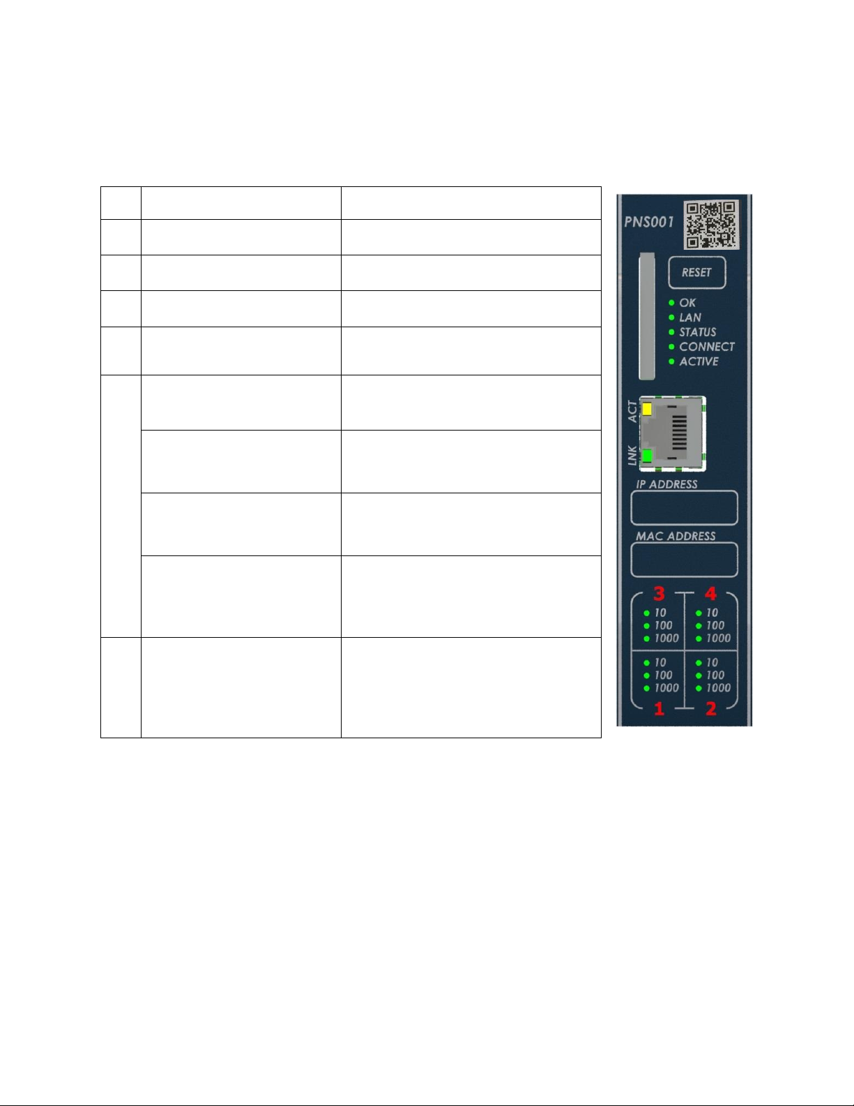
The PNS001 & PNS101
share the same front
panel markings except
for the catalog
number and QR code.
Page 6
6 RX3i PROFINET Scanner & Advanced PROFINET Scanner
GFK-2738Q IC695PNS001-BBBC & IC695PNS101-AAAA
Normal Operation of Individual LEDs
The PNS’s LEDs can operate in tandem to indicate fatal error, module location/identification, microprocessor overtemperature, and update conditions. For details on these blink patterns, refer to PACSystems RX3i PROFINET Scanner
Manual, GFK-2737.
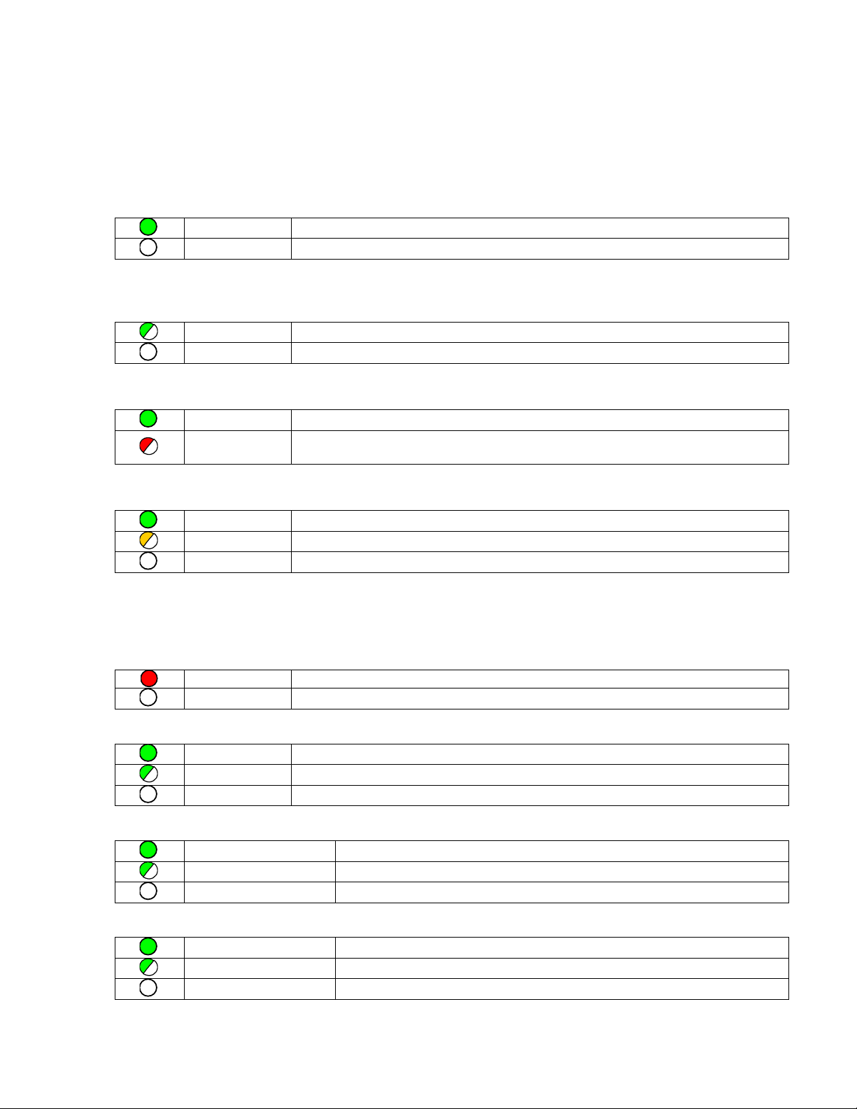
OK LED
The OK LED indicates whether the module is able to perform normal operation.
Green, on
OK
Off
Not OK
LAN LED
The LAN LED indicates access to and activity on the PROFINET network. The LAN LED indicates network packets are
being processed by the network interface (not just passing through the embedded switch).
Blinking on
The module’s network interface is active
Off
No activity
STATUS LED
The STATUS stays Green during normal operation.
Green, on
Normal Operation
Red, blinking
A MAC address read from nonvolatile memory is invalid. Ports with invalid MAC addresses
remain disconnected from the Ethernet network.
CONNECT LED (CONN on -AXXX versions)
The CONN LED indicates the status of PROFINET connections.
Green, on
At least one PROFINET connection (AR) exists with an I/O Controller.
Amber, blinking
No device name configured.
Off
No PROFINET connection (AR) exists.
Port LEDs
The PROFINET Scanner has four LEDs that indicate link speed, link connection and link activity corresponding to the
four possible external Ethernet ports.
Port Number LED
Red, on
Port 3 and 4 only: Error such as incompatible SFP.
Off
No Port error.
1000 Speed LED
Green on
Link connected, 1000 Mbps
Green blinking
Port active, 1000 Mbps
Off
The associated Ethernet port is not connected to an active link at 1000Mbps
100 Speed LED
Green, on
Link connected, 100 Mbps.
Green, blinking
Port active, 100 Mbps
Off
The associated Ethernet port is not connected to an active link at 100Mbps
10 Speed LED
Green, on
Link connected, 10 Mbps.
Green, blinking
Port active, 10 Mbps
Off
The associated Ethernet port is not connected to an active link at 10Mbps
Page 7

RX3i PROFINET Scanner & Advanced PROFINET Scanner 7
IC695PNS001-BBBC & IC695PNS101-AAAA GFK-2738Q
ACTIVE LED
The active LED indicates the Scanner is connected to a PROFINET I/O Controller that is controlling the I/O data for the
PNS’s I/O modules.
Green, on
PNS is connected to a PROFINET I/O Controller that is controlling I/O Module IO data.
Off
PNS is not connected to a PROFINET I/O Controller.
Front Panel LNK LED
The Front Panel LNK LED indicates link established on the front Ethernet port.
Green, on
Ethernet link established.
Off
No Ethernet link
Front Panel ACT LED
The front panel ACT LED indicates activity on the front Ethernet port when blinking.
Amber, blinking
Activity on front panel Ethernet port.
Amber, On
No activity on front Ethernet port, but link is connected
Off
No link is connected.
Page 8

8 RX3i PROFINET Scanner & Advanced PROFINET Scanner
GFK-2738Q IC695PNS001-BBBC & IC695PNS101-AAAA
Quick Start Guide
Installation and initial startup procedures for the PNS include the following steps. Before installing and operating the
PNS, refer to PACSystems RX3i PROFINET Scanner Manual, GFK-2737, for detailed information.
1. Pre-installation check
Upon receiving your RX3i equipment, carefully inspect all shipping containers for damage. If any part of the system is
damaged, notify the carrier immediately. The damaged shipping container should be saved as evidence for inspection
by the carrier.
As the consignee, it is your responsibility to register a claim with the carrier for damage incurred during shipment.
However, GE Intelligent Platforms will fully cooperate with you, should such action be necessary.
After unpacking the RX3i equipment, record all serial numbers. Serial numbers are required if you should need to
contact Customer Care during the warranty period. All shipping containers and all packing material should be saved
should it be necessary to transport or ship any part of the system.
2. Installing the PNS in an RX3i backplane
The Scanner can be installed in slot 1 or 2 of a 7, 12, or 16-slot RX3i Universal Backplane, or in slot 6 of a 7-slot RX3i
Universal Backplane. The installation slot must match the slot that is selected in the module’s hardware configuration.
▪ RX3i rack power must be turned off. The PNS does not
support insertion/removal while power is applied to the
system (hot swap).
▪ Holding the module firmly, align the module with the
correct slot and connector.
▪ Engage the module’s rear pivot hook in the notch on the top
of the backplane (1).
▪ Swing the module down (2) until the module’s connector
engages the backplane’s backplane connector.
▪ Visually inspect the module to be sure it is properly seated.
▪ Secure the bottom of the module to the backplane using the
machine screws provided with the module (3).
3. Connecting the PNS to the PROFINET network and to a
10BaseT, 100BaseTX or 1000BaseT IEEE 802.3 network
for general Ethernet communications
Do not connect two or more ports on the PNS to the same device, either directly or indirectly.
Each port on an RX3i PNS operates independently, so devices that operate at different speeds and/or duplex modes
may be attached to the ports. By default, all ports, including empty, unconfigured SFP cages, are set for Automatic,
which enables auto-negotiation for the widest range of options supported by the port. For other options, refer to
PACSystems RX3i PROFINET Scanner Manual, GFK-2737.
Port 1
Port 2
Port 3
Port 4
Bottom of module
Front
1 2 3
Page 9

RX3i PROFINET Scanner & Advanced PROFINET Scanner 9
IC695PNS001-BBBC & IC695PNS101-AAAA GFK-2738Q
4. Installing SFP devices
Optical SFPs use an invisible laser to generate a fiber-optic signal. Always keep the port covered if a
cable is not installed. Do not look into the open port if a cable is not installed.
If the surrounding air operating temperature of the PNS is greater than 40 °C, SFP devices
could have operating temperatures over 70°C (158 °F). Under these conditions, for your
safety, do not use bare hands to remove an SFP device from the SFP cage. Use protective
gloves or a tool (needle-nose pliers) to avoid handling the hot SFP device directly when
removing the SFP device.
For a list of SFP module types and network cabling details, refer to the section entitled SFP Modules for Ethernet Ports
in PACSystems RX3i PROFINET Scanner Manual, GFK-2737.
5. Assigning an I/O Device Name to the PNS
Before attempting to connect to or configure the RX3i PNS, the I/O Device Name must be set with a Discovery and
Configuration Protocol (DCP) tool, such as the Proficy Machine Edition Discovery Tool.
6. Configuring the PNS and its I/O Modules on a PROFINET network
Proficy Machine Edition is the primary tool used to configure an RX3i PROFINET network. The PNS must be installed in
the slot that is selected in the module’s hardware configuration. The GSDML file for the RX3i PNS is included in the
firmware upgrade kit. If the version of the GSDML file in the firmware upgrade kit is not already present in the Proficy
Machine Edition tool chest, import the newer GSDML into PME to enable new features.
Supported Modules, Power Supplies and Backplanes
The following modules can be used with this release of the RX3i PROFINET Scanner I/O Device:
Catalog Number
Module Description
Distinguishing Classes1
Discrete Input Modules
IC693ACC300
Input Simulator Module (8pt & 16pt operation)
8 in, 16 in
IC693MDL230
8 Circuit Input 120 Vac Isolated
8 in
IC693MDL231
8 Circuit Input 240 Vac Isolated
8 in
IC693MDL240
16 Circuit Input 120 Vac
16 in
IC693MDL241
16 Circuit Input 24 Vac / Vdc
16 in
IC693MDL250
16 Circuit Isolated Input 120 Vac, Input Filtering Off
16 in
IC693MDL250
16 Circuit Isolated Input 120 Vac, Input Filtering On
none
IC693MDL260
32 Circuit Input 120 Vac, Input Filtering Off
32 in
IC693MDL260
32 Circuit Input 120 Vac, Input Filtering On
32 in/out
IC693MDL632
8 Circuit Input 125 Vdc Positive / Negative Logic
8 in
IC693MDL634
8 Circuit Input 24 Vdc Positive / Negative Logic
8 in
IC693MDL635
16 Circuit Input 125 Vdc Positive / Negative Logic
16 in
IC693MDL645
16 Circuit Input 24 Vdc Positive / Negative Logic
16 in
1
The PNS cannot distinguish between modules within the same Distinguishing Class type. This means that any module physically
present that is within the same class as the one configured will not alert the user with a System Configuration Mismatch fault on
the Controller Fault Table. Refer to the section entitled CPU operation during System Configuration Mismatch Faults in PACSystems
RX7i and RX3i CPU Reference Manual, GFK-2222.
Page 10

10 RX3i PROFINET Scanner & Advanced PROFINET Scanner
GFK-2738Q IC695PNS001-BBBC & IC695PNS101-AAAA
Catalog Number
Module Description
Distinguishing Classes1
IC693MDL646
16 Circuit Input 24 Vdc Positive / Negative Logic Fast
16 in
IC693MDL648
16 Circuit Input 48 Vdc Positive / Negative Logic Fast
16 in
IC693MDL654
32 Circuit Input 5/12 Vdc Positive / Negative Logic
32 in
IC693MDL655
32 Circuit Input 24 Vdc Positive / Negative Logic Fast
32 in
IC693MDL660
32 Circuit Input 24 Vdc Positive / Negative Logic, Input Filtering Off
32 in
IC693MDL660
32 Circuit Input 24 Vdc Positive / Negative Logic, Input Filtering On
32 in/out
IC694ACC300
Input Simulator Module (8pt & 16pt Mode)
8 in, 16 in
IC694MDL230
8 Circuit Input 120 Vac Isolated
8 in
IC694MDL231
8 Circuit Input 240 Vac Isolated
8 in
IC694MDL240
16 Circuit Input 120 Vac
16 in
IC694MDL241
16 Circuit Input 24 Vac / Vdc
16 in
IC694MDL250
16 Circuit Input 120 Vac Isolated
none
IC694MDL260
32 Circuit Input 120 Vac
none
IC694MDL632
8 Circuit Input 125 Vdc Positive / Negative Logic
8 in
IC694MDL634
8 Circuit Input 24 Vdc Positive / Negative Logic
8 in
IC694MDL635
16 Circuit Input 125 Vdc Positive / Negative Logic
16 in
IC694MDL645
16 Circuit Input 24 Vdc Positive / Negative Logic
16 in
IC694MDL646
16 Circuit Input 24 Vdc Positive / Negative Logic Fast
16 in
IC694MDL648
16 Circuit Input 48 Vdc Positive / Negative Logic Fast
16 in
IC694MDL654
32 Circuit Input 5/12 Vdc Positive / Negative Logic
32 in
IC694MDL655
32 Circuit Input 24 Vdc Positive / Negative Logic Fast
32 in
IC694MDL658
32 Circuit Input 48 Vdc Positive / Negative Logic Fast
32 in
IC694MDL660
32 Circuit Input 24 Vdc Positive / Negative Logic
none
IC695MDL664
16 Circuit Smart Input 24 Vdc Positive Logic2
none
Discrete Output Modules
IC693MDL310
12 Circuit Output 120 Vac 0.5A
16 out
IC693MDL330
8 Circuit Output 120/240 Vac 2A
8 out
IC693MDL340
16 Circuit Output 120 Vac 0.5A
16 out
IC693MDL350
16 Circuit Output 120/240 Vac Isolated
16 out
IC693MDL390
5 Circuit Output 120/240 Vac 2A Isolated
8 out
IC693MDL730
8 Circuit Output 12/24 Vdc 2A Positive
8 out
IC693MDL731
8 Circuit Output 12/24 Vdc 2A Negative
8 out
IC693MDL732
8 Circuit Output 12/24 Vdc 0.5A Positive
8 out
IC693MDL733
8 Circuit Output 12/24 Vdc 0.5A Negative
8 out
IC693MDL734
6 Circuit Output 125 Vdc 1A Positive/Negative
8 out
IC693MDL740
16 Circuit Output 12/24 Vdc 0.5A Positive
16 out
IC693MDL741
16 Circuit Output 12/24 Vdc 0.5A Negative
16 out
IC693MDL742
16 Circuit Output 12/24 Vdc 1A Positive
16 out
IC693MDL748
8 Circuit Output 48 Vdc 0.5A Positive
8 out
IC693MDL752
32 Circuit Output 5/24 Vdc 0.5A Negative
32 out
IC693MDL753
32 Circuit Output 12/24 Vdc 0.5A Positive
32 out
IC693MDL754
32 Circuit Output 24 Vdc 0.75A Positive with ESCP, Diagnostics Off
32 out
2
The PNS currently does not support Fault Reporting from this module.
Page 11

RX3i PROFINET Scanner & Advanced PROFINET Scanner 11
IC695PNS001-BBBC & IC695PNS101-AAAA GFK-2738Q
Catalog Number
Module Description
Distinguishing Classes1
IC693MDL754
32 Circuit Output 24 Vdc 0.75A Positive with ESCP, Diagnostics On
32 in/out
IC693MDL758
32 Circuit Output 12/24 Vdc 0.5A Positive with ESCP2
32 out
IC693MDL760
Solenoid Valve Output Module
16 out
IC693MDL916
16 Circuit Output 4A Relay
16 out
IC693MDL930
8 Circuit Output 4A Relay Isolated
8 out
IC693MDL931
8 Circuit Output Relay Form BC Isolated
8 out
IC693MDL940
16 Circuit Output 2A Relay
16 out
IC694MDL310
12 Circuit Output 120 Vac 0.5A
16 out
IC694MDL330
8 Circuit Output 120/240 Vac 2A
8 out
IC694MDL340
16 Circuit Output 120 Vac 0.5A
16 out
IC694MDL350
16 Circuit Output 120/240 Vac Isolated
none
IC694MDL390
5 Circuit Output 120/240 Vac 2A Isolated
8 out
IC694MDL732
8 Circuit Output 12/24 Vdc 2A Positive
8 out
IC694MDL734
6 Circuit Output 125 Vdc 1A Positive/Negative
8 out
IC694MDL740
16 Circuit Output 12/24 Vdc 0.5A Positive
16 out
IC694MDL741
16 Circuit Output 12/24 Vdc 1A Negative
16 out
IC694MDL742
16 Circuit Output 12/24 Vdc 1A Positive
16 out
IC694MDL752
32 Circuit Output 5/24 Vdc 0.5A Negative
32 out
IC694MDL753
32 Circuit Output 12/24 Vdc 0.5A Positive
32 out
IC694MDL754
32 Circuit Output with ESCP
none
IC694MDL758
32 Circuit Output 12/24 Vdc 0.5A Positive with ESCP2
none
IC694MDL916
16 Circuit Output 4A Relay
none
IC694MDL930
8 Circuit Output 4A Relay Isolated
8 out
IC694MDL931
8 Circuit Output Relay Form BC Isolated
8 out
IC694MDL940
16 Circuit Output 2A Relay
16 out
IC695MDL765
16 Circuit Smart Output 24/125 Vdc 2A Positive Logic2
None
Discrete Mixed Modules
IC693MAR590
8 Circuit Mixed 120 Vac Input / Relay Output
8 in/out
IC693MDR390
8 Circuit Mixed 24 Vdc Input / Relay Output
8 in/out
Analog Input Modules
IC693ALG220
4 Point Analog Voltage Input
ALG IN 4
IC693ALG221
4 Point Analog Current Input
ALG IN 4
IC693ALG222
16 Point Analog Voltage Input
ALG IN 16
IC693ALG223
16 Point Analog Current Input
ALG IN 16
IC694ALG220
4 Point Analog Voltage Input
ALG IN 4
IC694ALG221
4 Point Analog Current Input
ALG IN 4
IC694ALG222
16 Point Analog Voltage Input
ALG IN 16
IC694ALG223
16 Point Analog Current Input
ALG IN 16
IC695ALG106
6 Point Isolated Analog Input Current/Voltage3
none
IC695ALG112
12 Point Isolated Analog Current/Voltage Input3
none
3
PNS currently does not support Fault Reporting or Interrupts from this module. Also, only Type A and Type B counters are
supported.
Page 12

12 RX3i PROFINET Scanner & Advanced PROFINET Scanner
GFK-2738Q IC695PNS001-BBBC & IC695PNS101-AAAA
Catalog Number
Module Description
Distinguishing Classes1
IC695ALG600
8 Point Universal Analog Input Module3
none
IC695ALG608
8 Point Analog Input Current / Voltage Input3
none
IC695ALG616
16 Point Analog Current / Voltage Input3
none
IC695ALG626
16 Point Analog Current / Voltage Input3 (HART4 Support)
none
IC695ALG628
8 Point Analog Current / Voltage Input3 (HART4 Support)
none
Analog Output Modules
IC693ALG390
2 Point Analog Voltage Output
ALG OUT 2
IC693ALG391
2 Point Analog Current Output
ALG OUT 2
IC693ALG392
8 Point Analog Current / Voltage Output
ALG OUT 8
IC694ALG390
2 Point Analog Voltage Output
ALG OUT 2
IC694ALG391
2 Point Analog Current Output
ALG OUT 2
IC694ALG392
8 Point Analog Current / Voltage Output
ALG OUT 8
IC695ALG704
4 Point Analog Current / Voltage Output3
none
IC695ALG708
8 Point Analog Current / Voltage Output3
none
IC695ALG728
8 Point Analog Current / Voltage Output3 (HART4 Support)
none
IC695ALG808
8 Point Isolated Analog Current / Voltage Output3
none
Analog Mixed Modules
IC693ALG442
4 Input / 2 Output, Current / Voltage
ALG IN 4, ALG OUT 2
IC694ALG442
4 Input / 2 Output, Current / Voltage
ALG IN 4, ALG OUT 2
RTD Input Modules
IC695ALG508
8 Channel Isolated RTD Input3
none
Thermocouple Input Modules
IC695ALG312
12 Point Isolated Thermocouple Input3
none
IC695ALG412
12 Point Isolated High Speed Thermocouple Input3
none
High-speed Counter Modules
IC695HSC304
High-speed Counter Module - 4 Counters3
None
IC695HSC308
High-speed Counter Module - 8 Counters3
None
Specialty Modules
IC694PSM001
Power Sync and Measurement Module
none
Power Supply Modules
IC695PSA040
Universal 120/240 Vac, 125Vdc 40W Power Supply
none
IC695PSA140
Multifunctional 120/240 Vac, 125Vdc 40W Power Supply
none
IC695PSD040
24Vdc 40W Power Supply
none
IC695PSD140
Multifunctional 24Vdc 40W Power Supply
none
Small Form-factor Pluggable (SFP) Modules
IC695SPC100
10/100/1000Base-T Copper SFP
none
IC695SPF002
100Base-FX (fiber 2km) SFP
none
IC695SPF010
1000Base-LX (fiber 10km) SFP
none
4
PNS firmware version 2.30 or later supports the HART Pass Through capabilities of this module. PNS firmware version 2.41 or later
supports Remote Get HART Device Information COMMREQ support only (no HART variables in IO Data). HART-compatible CPU and
PNC001 versions are required.
Page 13

RX3i PROFINET Scanner & Advanced PROFINET Scanner 13
IC695PNS001-BBBC & IC695PNS101-AAAA GFK-2738Q
Catalog Number
Module Description
Distinguishing Classes1
IC695SPF550
1000Base-SX (fiber 550m) SFP
none
The RX3i PROFINET Scanner can be used in the following PACSystems backplanes:
Catalog Number
Backplane Type5
IC695CHS007
7-Slot RX3i Universal Backplane
IC695CHS012
12-Slot RX3i Universal Backplane
IC695CHS016
16-Slot RX3i Universal Backplane
5
The PNS001 cannot distinguish between the different rack sizes. Choosing the wrong type will not generate a System Configuration
Mismatch fault on the Controller Fault Table.
Page 14

14 RX3i PROFINET Scanner & Advanced PROFINET Scanner
GFK-2738Q IC695PNS001-BBBC & IC695PNS101-AAAA
Release History
Version
Firmware
Revision
Date
Comments
IC695PNS001-BBBC
IC695PNS101-AAAA
3.10
Aug
2018
Initial release of the IC695PNS101 Advanced PROFINET Scanner. Added support
for the IC695HSC304 High Speed Counter Module with 4 Counters. Resolves
issues described in the section titled Problems Resolved by this Revision.
IC695PNS001-BBBB
3.01
Jan
2018
Hardware change which increases isolation between Earth ground and signal
ground. Removes incorrect statement in IPI revision N regarding RX3i
backplane compatibility.
IC695PNS001-BABB
3.01
Aug
2017
Addresses issue with SDcard communication on some assemblies.
IC695PNS001-BABA
3.00
Feb
2017
New hardware platform with new layout of front panel LEDs and Ethernet
connector replaces front panel USB for firmware update. Firmware not
compatible with previous hardware revisions (-AXXX).
IC695PNS001-BABA is Achilles Level 1 Certified.
IC695PNS001-ABAK
2.41
Jun
2016
Added support for the Remote Get HART Device Information COMMREQ.
Information from a HART device connected to an RX3i Analog Module in an
IC695PNS001 RX3i PROFINET Scanner may be read into the user application
using the Remote Get HART Device Information COMMREQ.
IC695PNS001-ABAJ
2.40
Nov
2015
Added support for additional RX3i I/O modules (ALG106, ALG312, ALG314,
ALG608, ALG628, ALG704, and MDL758)
IC695PNS001-ABAH
2.30
May
2015
Added support for HART® Pass Through feature set using HART-capable RX3i
Analog modules. Also added support for I/O Module Version information via
Explore PROFINET Networks in PME.
IC695PNS001-ABAG
2.20
Jun
2014
Added support for IC695ALG600 (Universal Analog Input Module) and
IC694PSM001 (Power and Sync Measurement Module).
IC695PNS001-ABAF
2.10
Apr
2014
Added support for IC695HSC308 (High-speed Counter – 8 Counters). Resolution
of ALG508, ALG616, and ALG708 modules larger configuration causing an IOC
Software - Module Firmware Fault when more than three were placed in a
PNS001 rack.
IC695PNS001-ABAE
2.00
Mar
2014
Added PROFINET System Redundancy (S2 NAP – supports Redundant
connections from two IO Controllers).
Resolution of PROFINET connection losses and RX3i PNS001 connection issues,
described below.
Added support for additional RX3i I/O modules (ALG112, ALG626 (No HART),
ALG728 (No HART), and ALG808)
IC695PNS001-ABAD
1.11
Nov
2013
Resolution to Analog Output Anomaly issue, described in PACSystems RX3i
PROFINET Scanner IPI, GFK-2738D.
IC695PNS001-ABAC
1.10
Jul
2013
Support for additional RX3i I/O modules (MDL664, MDL765, ALG508, ALG616,
ALG708).
IC695PNS001-ABAA
1.00
Jun
2013
Hardware update for improved manufacturability. No changes to features,
functions or compatibility
IC695PNS001-AAAA
1.00
Mar
2013
Initial release.
®
HART® is a registered trademark of the HART Communication Foundation of Austin, Texas USA. Any use of the term HART hereafter
in this document, or any document referenced by this document, implies the registered trademark.
Page 15

RX3i PROFINET Scanner & Advanced PROFINET Scanner 15
IC695PNS001-BBBC & IC695PNS101-AAAA GFK-2738Q
Important Product Information for this Release
Field Upgrade
Upgrade Kit: 41G2416-FW01-000-A2.zip
Only IC695PNS001-Bxxx and IC695PNS101-Axxx or later revisions are field upgradable to this release using the upgrade
kit listed above. IC695PNS001-Axxx modules cannot be upgraded with this kit due to hardware and firmware design
changes in the PNS001-Bxxx revision.
New Features and Enhancements
• Initial release of the IC695PNS101 Advanced PROFINET Scanner with Sequence of Events support.
• Added support for the IC695HSC304 High Speed Counter Module with 4 Counters.
Problems Resolved by this Revision
RX3i PROFINET Scanner Release 3.10 resolves the following issues:
Subject
Description
Cyber Security Updates
Security enhancements were made to the PNS001-Bxxx to harden the
product against an attacker.
Page 16

16 RX3i PROFINET Scanner & Advanced PROFINET Scanner
GFK-2738Q IC695PNS001-BBBC & IC695PNS101-AAAA
Functional Compatibility
The following CPU firmware, programming software and backplane hardware versions are required to use the features
introduced in the most recent PNS release:
Subject
Description
Feature
Minimum PNS Version Required
Minimum Version Required
Firmware
Version
PNS101
Sequence of Events
PNS101 Release 3.10
CPE330 Release 9.60
PNS001-Bxxx
PNS001-Bxxx Release 3.00
CPU320/CPU315 Release 8.95
CPE310/CPE305 Release 8.95
CRU320 Release 8.95
CPE330 Release 8.95
CPE400 Release 9.00
CPL410 Release 9.55
CPE100 Release 9.15
CPE115 Release 9.45
RXi Controller Release 7.806
PNS001-Axxx
(Most Recent Release)
PNS001-Axxx Release 2.41
CPU320/CPU315 Release 8.95
CPE310/CPE305 Release 8.95
CRU320 Release 8.95
CPE330 Release 8.95
CPE400 Release 9.00
CPL410 Release 9.55
CPE100 Release 9.15
CPE115 Release 9.45
RXi Controller Release 7.806
Programmer
software
PNS001 & PNS101: Proficy Machine Edition version 8.50 SIM 2 or later
GSDML Version
PNS101
PNS101 Release 3.10
GSDML-V2.3-GEIP-RX3iPNS-
20180724.xml
IC695HSC304
PNS001-Bxxx Release 3.10
PNS101 Release 3.10
GSDML-V2.3-GEIP-RX3iPNS-
20180724.xml
PNS001-Bxxx
PNS001-Bxxx Release 3.00
GSDML-V2.3-GEIP-RX3iPNS-
20170109.xml
PNS001-Axxx
(Most Release Release)
PNS001-Axxx Release 2.41
GSDML-V2.3-GEIP-RX3iPNS-
20160602.xml
RX3i PNC001
PROFINET
Controller
PNS001-Axxx
(Most Recent Release)
PNS001-Bxxx
PNS101
(Sequence of Events
Disabled)
PNS001-Axxx Release 2.41
PNS001-Bxxx Release 3.00
PNS101 Release 3.10
IC695PNC001 Release 2.26
6
HART Pass Through COMMREQ feature not supported on RXi Controller. Refer to future RXi Controller IPI for updates.
Page 17

RX3i PROFINET Scanner & Advanced PROFINET Scanner 17
IC695PNS001-BBBC & IC695PNS101-AAAA GFK-2738Q
RX3i backplane
hardware
The following minimum backplane hardware revision must be used:
IC695CHS012-BAMP IC695CHS016-BAMP
IC695CHS012CA-BAMP IC695CHS016CA-BAMP
or
IC695CHS012-CA (or later) IC695CHS016-CA (or later)
IC695CHS012CA-CA (or later) IC695CHS016CA-CA (or later)
or
IC695CHS007-AA (or later)
When installing, operating, or maintaining the PNS, personnel must ensure any electrostatic charge
is discharged through the use of a grounded ESD strap or other means.
Rx3i AC Power
Supply
Compatibility
For new installations using AC power supplies, the PNS requires an IC695PSA040H or
IC695PSA140D (or higher) revision power supply to ensure compatibility.
For retrofit installations using AC power supplies, the PNS may require an IC695PSA040H or
IC695PSA140D (or higher) revision power supply depending on the total current load in the
backplane. If the total current load exceeds the existing power supply's minimum current
threshold, no power supply change is required.
Small formfactor pluggable
modules
IC695SPC100A or later
IC695SPF002A or later
IC695SPF550A or later
IC695SPF010A or later
RX3i modules
For a complete list, refer to Supported Modules, Power Supplies and Backplanes.
Restrictions and Open Issues
Subject
Description
N/A
N/A
Page 18

18 RX3i PROFINET Scanner & Advanced PROFINET Scanner
GFK-2738Q IC695PNS001-BBBC & IC695PNS101-AAAA
Operational Notes
Subject
Description
Invalid Module Configurations
will cause the respective RX3i
I/O module to fail
configuration
When the PNS rejects the configuration of an individual I/O module, that
configuration is not delivered to the I/O module, leaving the module in an unconfigured state. In many modules, this is indicated by the OK Led on the I/O Module
blinking. In addition, I/O point faults will be asserted for that module’s I/O. Correct
the configuration of the I/O module and store HWC again.
Refer to the section entitled RX3i PROFINET Scanner Configuration Validation in
PACSystems RX3i PROFINET Scanner Manual, GFK-2737.
Analog Modules do not
configure if Alarms are outside
High and Low Scale Value
Engineering Units.
For analog input and output modules that support alarms, the PNS limits alarm
values to the range specified by the High and Low Engineering Unit values. If the
High and Low Scale A/D Unit values are not the full range of the analog signal,
runtime values reported in Engineering Units may exceed the High or Low
Engineering range. Alarms cannot be configured for this range outside of the
Engineering Units range.
For example, consider an input channel with Range Type as Voltage/Current and
Range selection of -10V to +10V, 16-bit Integer format. If High and Low Scale Eng
Units are set to 8500 and -8500 and the High and Low Scale A/D Units are set to 8
and -8, the alarm range will be limited to a range of -8500 to 8500. Analog input
signals of -10V and +10V correspond to Engineering Unit values of -10625 and
10625. To support alarm values at all possible values of the analog signal, scaling
values should be chosen such that the A/D Units are specified as the high and low
limits for the analog signal. In this example, the High and Low Engineering units
would be 10625 and -10625 with High and Low A/D Units of 10 and -10.
IOPS of power supplies do not
update when power supply is
switched off
The IOPS (status) of a power supply is marked good or bad at the start of each
PROFINET I/O connection. The IOPS is not updated when the power supply is turned
on and off.
PROFINET Alarms are not
supported
PROFINET Alarms are not issued from the RX3i PNS in this release.
Some power supplies use two
backplane slots, but this is not
indicated in the change
module list interface of HWC
Note that the IC695PSA040 and IC695PSA140 each utilize two backplane slots but
are shown using only one slot in the Change Module List interface for the RX3i PNS.
Configuring a module for the already utilized slot will result in a Loss of I/O Module
fault.
PNS module supported in
certain backplane slots only.
The RX3i PROFINET Scanner module is configurable for use in Slot 1, Slot 2, and when
installed in the IC695CHS007 backplane, also Slot 6.
SFP modules do not support
hot swap
SFP modules do not support hot swap. This means that if an SFP module is hotinserted into the RX3i PNS, no Fault Table entry will be logged, and configuration
parameters will not be applied to the SFP until the RX3i PNS is power cycled. Until
the RX3i PNS is power cycled, the SFP will remain enabled and active with auto
negotiation turned on.
I/O modules hot inserted while
an invalid configuration is
stored require re-insertion or
power cycle to recover
If an invalid configuration for an I/O module in the PNS is stored to the CPU, such as
a default value outside the engineering units range, and the I/O module using that
configuration is hot inserted in the PNS, the hot insertion process fails. No Addition
of I/O Module fault is generated, and the module is left at its default operation. The
configuration of that module will not be retried until the module is re-inserted or the
PNS rack is power cycled, even if the configuration is corrected in the CPU.
Page 19

RX3i PROFINET Scanner & Advanced PROFINET Scanner 19
IC695PNS001-BBBC & IC695PNS101-AAAA GFK-2738Q
Subject
Description
Quickly changing data may not
be detected in PLC Logic solve
Quickly changing I/O or Module Data such as event flags on a High Speed Counter
module may not be detected in the CPU logic scan. Only event data which is latched
and acknowledged or persists for the Update I/O Rate plus the CPU Logic Scan rate is
guaranteed to be detectable from logic.
Connecting Ethernet Ports Not
Configured as Ring Ports to the
MRP Ring May Inhibit RingBreak Detection
In order to insure correct MRP ring-break detection, it is important to connect the
correct Ethernet ports of the RX3i PNS to the MRP ring. The ports connected to the
ring must be the same ports configured as MRP Ring Ports. Failure to connect the
configured ports will prevent the PNS from correctly participating in the MRP ring,
may inhibit ring-break detection, and may result in losses of IO Devices upon ringbreak events. It is recommended during system commissioning that the physical
network connections be verified with the system configuration for ring ports in
system’s hardware configuration. Refer to section “Media Redundancy Protocol
Support” of PACSystems RX3i PROFINET Scanner Manual, GFK-2737, for details on
recommended MRP configuration.
Reset Password returns HTTP
ERROR 503, service
unavailable, after restart.
On power-up, the PNS generates a local security certificate to use with HTTPS
communications. Until this process has completed, attempts to enter the secure
webpages used to reset the password will fail with error 503. This can take from 15120 seconds.
ALG616, ALG626, & ALG628
Terminal Block Present Status
Bit
IC695ALG616-Fx, IC695ALG626-Fx, and IC695ALG628-Fx (and later hardware
revision) analog modules may not set the terminal block present status bit in their
module status after a PNS firmware update completes, even if the terminal block is
installed. Normal operation of the terminal block present status bit may be restored
by removing and reinstalling the terminal block or power cycling the rack.
MDL660 does not show correct
firmware revision after PNS
firmware update
IC694MDL660 may report incorrect primary and boot firmware through the Explore
PROFINET Networks dialogs in Proficy Machine Edition in a PNS rack after firmware
update of the PNS. Correct versions will be reported after the next power cycle of
the MDL660 module either through a power cycle of the entire rack or removing and
reinstalling the MDL660 module.
QR Code may not link
automatically link to product
landing page
Some older mobile QR Code Scanner/Reader applications may not correctly link to
the target site. This behavior has not been identified to exist on some new QR
Scanner apps. An example of one that has been verified to work correctly is the QR
Code Scanner in Google Chrome for Android and iOS.
PNS001-Axxx Reset or Power
Supply Fault with PSA140
These issues may occur in a PNS001-Axxx remote IO drop with two IC695PSA140
Multifunctional 120/240 VAC, 125VDC 40W Power Supplies when either of the
power is turned off and back on:
1. The PNS001-Axxx resets and does not power back on.
2. The P/S Fault LED on PSA140 that was not powered off and back on turns
on and no power is supplied to the modules in the RX3i rack.
If this issue occurs, it may be resolved by turning both power supplies off and back
on. This issue only applies to the PNS001-Axxx.
Rx3i DC Power Supply Wiring
Recommendations
The negative side of the 24V input must be connected to earth ground when using
RX3i DC power supplies. Refer to PACSystems RX3i System Manual, GFK-2314 for
additional information.
Page 20

20 RX3i PROFINET Scanner & Advanced PROFINET Scanner
GFK-2738Q IC695PNS001-BBBC & IC695PNS101-AAAA
1-800-433-2682
1-434-978-5100
http://www.geautomation.com/
Additional Information
For additional information, please refer to the manuals listed below. Manuals can be downloaded from the support
website, http://support.ge-ip.com.
PACSystems RX7i, RX3i, and RSTi-EP CPU Reference Manual
GFK-2222
PACSystems RX3i & RSTi-EP PROFINET I/O Controller User Manual
GFK-2571
PACSystems RX3i PROFINET Controller Command Line Interface Manual
GFK-2572
PACSystems RX3i PROFINET IO-Scanner User Manual
GFK-2737
PACSystems RX3i CEP PROFINET Scanner User Manual
GFK-2883
PROFINET I/O Devices Secure Deployment Guide
GFK-2904
PACSystems RXi, RX3i, RX7i, and RSTi-EP Controller Secure Deployment Guide
GFK-2830
PACSystems HART Pass Through User Manual
GFK-2929
PACSystems RX3i System Manual
GFK-2314
PACSystems RX3i Sequence of Events User Manual
GFK-3050
 Loading...