

Page 1

GE’s
g
Automation & Controls
Programmable Control Products
PACSystems* RX3i 1GHz
64MB CPU w/Ethernet
IC695CPE330 Quick Start
Guide
GFK-2941E
May 2016
Page 2

Contents
1. User Features ................................................................................................................. 2
1.1. Switches ............................................................................................................ 4
1.2. Light-Emitting Diode Indicators (LEDs) .................................................................. 5
1.3. Ethernet Ports .................................................................................................... 6
2. Hardware Installation................................................................................................... 9
2.1. Initial Checks ...................................................................................................... 9
2.2. Installation Location ........................................................................................... 9
2.3. Installation in Hazardous Areas ..........................................................................10
2.4. Grounding .........................................................................................................10
3. Module Start-up ........................................................................................................... 11
3.1. You Will Need: ...................................................................................................11
3.2. Basic Installation Steps:......................................................................................11
3.3. Redundancy Configuration .................................................................................12
3.4. PROFINET Controller Configuration .....................................................................13
3.5. Backward Compatibility with CPU320/CRU320/CPU315 .......................................13
3.6. Removable Data Storage Device (RDSD) ..............................................................16
4. Periodic Maintenance ................................................................................................. 16
4.1. Real-Time Clock Battery .....................................................................................16
4.2. Spare Parts .......................................................................................................16
5. Additional Information ............................................................................................... 17
i PACSystems* RX3i 1GHz 64MB CPU w/Ethernet Quick Start Guide GFK-2941E
Page 3

The PACSystems* RX3i CPE330 is a richly
The CPE330 is programmed and configured
•
Simplex PROFINET I/O Controller with
support for up to 32 I/O devices and update rates of 1 – 512ms. I/O device update rates
devices configured, update rates of 16ms and higher are available.
• Supports two independent 10/100/1000 Ethernet LANs. As shown in Figure 1, LAN1
internally-switched RJ-45 connectors.
1. User Features
featured programmable controller CPU
equipped with a 1GHz dual-core
microprocessor, 64Mbytes of built-in
program memory and two independent
high-speed Ethernet interfaces. It is ideally
suited for multi-tier communications and for
synchronizing large amounts of data. Its
metal housing provides superior noise
immunity.
over Ethernet via GE’s Proficy* Machine
Edition (PME) software. It resides in the RX3i
main rack and supports all RX3i I/O and
Intelligent Option modules, up to 32K I/O
points.
RX3i Hot Standby Redundancy CPU with
support for PROFINET I/O using
IC695PNC001 PROFINET Controllers.
• RX3i Hot Standby Redundancy with
Ethernet (EGD) & Genius I/O.
•
Figure 1: IC695CPE330 Features at a Glance
of 8ms and faster are possible with 16 or fewer devices. When there are more than 16
attaches via the upper, dedicated RJ-45 connector. LAN2 attaches via the lower pair of
GFK-2941E May 2016 2
Page 4

•
additional HART-compatible products.)
The embedded Ethernet interface is supported by a dedicated microprocessor core. This
dedicated processing capability permits the CPU to support these two LANs with:
o up to 48 simultaneous SRTP Server connections;
o up to 16 simultaneous Modbus/TCP Server connections;
o 32 Clients are permitted; each may be SRTP or Modbus/TCP.
o OPC UA Server with support for up to 5 concurrent sessions with up to 10
concurrent variable subscriptions and up to 12,500 variables;
o up to 255 simultaneous Class 1 Ethernet Global Data (EGD) exchanges;
o two independent Redundant IP addresses, one for each of the embedded
Ethernet LANs.
• Achilles Level 2 Communications Certification
1
.
• Optional Energy Pack, IC695ACC402, allows CPE330 to instantly save user memory to
non-volatile storage in the event of loss of power.
• Ability to transfer user programs and/or data to and from USB 2.0 A type Removable
Data Storage Devices (RDSDs).
• HART Pass Through allows the CPE330 to communicate HART asset management data
between HART-capable I/O modules and PC-based asset management tools. (Requires
• User may program in Ladder Diagram, Structured Text, Function Block Diagram, or C.
• Contains 64Mbytes of configurable data and program memory.
• Supports auto-located Symbolic Variables that can use any amount of user memory.
• Reference table sizes include 32k bits for discrete %I and %Q and up to 32k words
each for analog %AI and %AQ. Bulk memory (%W) also supported for data
exchanges.
• Supports up to 512 program blocks. Maximum size for a block is 128KB.
• For supported I/O, Communications, Motion, and Intelligent modules, refer to the
PACSystems RX3i System Manual, GFK-2314.
1
Achilles Level 2 Communications Certification available in CPE330 R8.80
3 PACSystems* RX3i 1GHz 64MB CPU w/Ethernet Quick Start Guide GFK-2941E
Page 5

RDSD Pushbuttons
Function
RDSD UPLD
Loads user program or data from CPU to RDSD.
RDSD DNLD
Stores user program or data from RDSD to CPU.
Run/Stop
A three-position switch which operates as follows:
CPU and Sweep Mode
Memory Protection
The CPU runs with I/O
sweep enabled.
The CPU runs with outputs
disabled.
The CPU is not allowed to
go into Run mode.
User program memory can be
written.
• Ability to display serial number and date code in PME Device Information Details.
• Operating temperature range 0°C to 60°C (32 °F to 140 °F).
1.1. Switches
The Run/Stop switch and RDSD UPLD and RDSD DNLD pushbuttons are located
behind the protective front door. Switch operation is given in the following table.
Switch Position
Run I/O
Run
Stop
The Run/Stop switch is enabled by default; it can be disabled in the PME Hardware
Configuration (HWC) settings. The memory protection function of this switch can be
disabled separately in HWC. The memory protection functionality is disabled by default.
GFK-2941E May 2016 4
User program memory is read only.
User program memory is read only.
Page 6
CPU OK
On Green
CPU has passed its power-up diagnostics and is
complete.)
Off
Power is not applied or CPU has a problem, which
may be indicated by blink pattern.
Blinking
CPU in Stop-Halt state; possible watchdog timer
to fault tables.
CPU OK
On Amber
CPU indicating CPU320/CRU320 compatibility setting
FORCE
On Amber
Refer to the section, Backward Compatibility with
CPU320/CRU320/CPU315 for more information.
RUN
Blinking in
CPU is updating an internal programmable hardware
OUT EN
RUN
On Green
CPU is in Run mode.
Off
CPU is in Stop mode.
OUT EN
On Green
Output scan is enabled.
Off
Output scan is disabled.
FORCE
On Amber
Override is active on a bit reference.
Off
No Overrides active in I/O Reference Tables.
RDSD
On Green
USB Device detected (No Activity)
Blinking
Green
Port activity detected on USB Interface
1.2. Light-Emitting Diode Indicators (LEDs)
Status Indicators
LED LED State Operating State
Other
LEDs off
unison
functioning properly. (After initialization sequence is
fault. If the programmer cannot connect, cycle
power with charged Energy Pack attached and refer
device.
5 PACSystems* RX3i 1GHz 64MB CPU w/Ethernet Quick Start Guide GFK-2941E
Page 7

Off
No port activity detected on USB Interface
On Red
RDSD Failure
Blinking
Red
Target name mismatch: Press same RDSD
pushbutton again to dismiss.
SYS FLT
On Red
CPU is in Stop/Faulted mode: a fatal fault has
occurred.
Off
No fatal faults detected.
LED
LED State
Operating State
LINK
On Green
The corresponding link is physically connected.
Blinking
Green
Traffic is detected at the corresponding port.
Off
No connection detected at corresponding port.
1Gbps
On Amber
(LAN1) or
Corresponding network data speed is 1 Gbps.
On Green
(LAN2)
Corresponding network data speed is 100 Mbps or
10 Mbps.
LED LED State Operating State
CPE330 Ethernet Indicators
(upper)
(lower)
Off
1.3. Ethernet Ports
LAN1 connects to the uppermost RJ-45 connector. It is not switched. LAN2 connects
to the two lower RJ-45 connectors. They are switched internally. Record the IP
Address of each LAN in the space provided (Figure 1).
Each of the embedded Ethernet interfaces automatically senses the data rate
(10 Mbps or 100 Mbps or 1 Gbps), communications mode (half-duplex or full-duplex),
and cabling arrangement (straight-through or crossover) of the attached link.
GFK-2941E May 2016 6
Page 8

CPE330 LAN1
CPE330 LAN2
IP Address:
192.168.0.100
10.10.0.100
Subnet Mask:
255.255.255.0
255.255.255.0
Gateway:
0.0.0.0
0.0.0.0
For improved performance, the two Ethernet LANs are serviced by a dedicated
microprocessor core. In addition, each Ethernet LAN is serviced by a dedicated
Network Interface Controller (NIC). In this way, the servicing of the Ethernet ports is
independent of the controller logic and I/O scanning. This superior level of servicing is
required at the higher communications rates.
Any of the embedded Ethernet ports may be used to communicate with the PME
programming software using the Service Request Transport Protocol (SRTP, a
proprietary GE protocol, used primarily for communication with the programmer).
To establish Ethernet communications between the PME programming and
configuration software and the CPU, you first need to set an IP address. Use the
Set IP Address tool (refer to PACSystems RX3i and RX7i CPU Reference Manual,
GFK-2222V) or use the factory-shipped default settings:
7 PACSystems* RX3i 1GHz 64MB CPU w/Ethernet Quick Start Guide GFK-2941E
Page 9

Figure 2: Typical Multi-tier LAN Application
A typical application will take advantage of the two independent LANs. The dedicated
LAN1 port will be used for communications with plant-level or supervisory layers. The
switched LAN2 will typically be used to communicate with devices within the
manufacturing cell or process, including local HMI devices and micro-controllers.
GFK-2941E May 2016 8
Page 10

2. Hardware Installation
2.1. Initial Checks
Upon receiving your RX3i equipment, carefully inspect all shipping containers for
damage. If any part of the system is damaged, notify the carrier immediately. The
damaged shipping container should be saved as evidence for inspection by the
carrier.
As the consignee, it is your responsibility to register a claim with the carrier for
damage incurred during shipment. GE’s Automation & Controls will fully cooperate
with you, however, should such action be necessary.
After unpacking the RX3i equipment, record all serial numbers. Serial numbers are
required if you should need to contact Customer Care during the warranty period. All
shipping containers and all packing material should be saved should it be necessary
to transport or ship any part of the system.
Verify that all components of the system have been received and that they agree
with your order. If the system received does not agree with your order, contact
Customer Care.
2.2. Installation Location
This product is intended for use with the RX3i system. Its components are considered
open equipment (having live electrical parts that may be accessible to users) and
must be installed in an ultimate enclosure that is manufactured to provide safety. At
a minimum, the enclosure shall provide a degree of protection against solid objects
as small as 12mm (e.g. fingers). This equates to a NEMA/UL Type 1 enclosure or an
IEC60529 IP20 rating providing at least a pollution degree 2 environment. For details
about installing RX3i rack systems, refer to the PACSystems RX3i System Manual,
GFK-2314.
If you need technical help, contact Technical Support. For phone numbers and email
addresses, refer to the back cover of this Guide.
9 PACSystems* RX3i 1GHz 64MB CPU w/Ethernet Quick Start Guide GFK-2941E
Page 11

2.3. Installation in Hazardous Areas
The following information is for products bearing the UL marking for Hazardous Areas
or ATEX marking for explosive atmospheres:
CLASS 1 DIVISION 2 GROUPS ABCD
• This equipment is an open-type device and is meant to be installed in an
enclosure suitable for the environment that is only accessible with the use
of a tool.
• Suitable for use in Class I, Division 2, Groups A, B, C and D Hazardous
Locations, or nonhazardous locations only.
• WARNING - EXPLOSION HAZARD - SUBSTITUTION OF COMPONENTS MAY
IMPAIR SUITABILITY FOR CLASS I, DIVISION 2.
• WARNING - EXPLOSION HAZARD - WHEN IN HAZARDOUS AREAS, TURN OFF
POWER BEFORE REPLACING OR WIRING MODULES.
ATEX Zone 2
This module must be mounted in an enclosure certified in accordance with EN6007915 for use in Zone 2, Group IIC and rated IP54. The enclosure shall only be able to be
opened with the use of a tool.
2.4. Grounding
The RX3i rack into which this product will be mounted must be grounded per the
instructions provided in PACSystems RX3i System Manual, GFK-2314. Also, if an
Energy Pack (IC695ACC402) is connected, its ground-strap must be grounded as
described in PACSystems RX3i Energy Pack IC695ACC402 Quick Start Guide,
GFK-2939.
GFK-2941E May 2016 10
Page 12

3. Module Start-up
3.1. You Will Need:
• An RX3i Universal Backplane: IC695CHS007, IC695CHS012 or IC695CHS016.
• This PACSystems RX3i CPU. This CPU occupies two backplane slots.
• An RX3i rack-mounted Power Supply Module and compatible power source (AC
or DC).
• A computer running Proficy Machine Edition (PME) configuration and
programming software. PME Version 8.60 SIM 8 or later supports all features in
this document.
• Ethernet cable for connecting the PME programmer computer to the RX3i CPU.
• Phillip’s head screwdriver.
• Very small slotted screwdriver (1.4mm jeweler’s size).
3.2. Basic Installation Steps:
For startup and configuration of the CPE330, complete the following steps. For full
details on CPE330 operation, refer to the PACSystems RX3i and RX7i CPU Reference
Manual, GFK-2222V or later.
1. Turn power off at the RX3i rack and install the CPE330 in a double-slot which is
CPU-compatible (refer to PACSystems RX3i System Manual, GFK-2314 Chapter 3).
Typically, the CPU is located in the left-most slot pair, or in the pair of slots to the
right of the power supply module.
2. If used, mount the compatible RX3i Energy Pack (IC695ACC402) within 3 feet of
the CPU. The dedicated interconnect cable attaches to the underside of CPE330.
Follow interconnect and grounding instructions in PACSystems RX3i Energy Pack
2
Note: on lightly-loaded racks, use IC695PSA040H or later, or IC695PSA140D or later,
otherwise power-up may be unsuccessful. Alternately, fill out the empty slots in the
rack so as to draw more current.
11 PACSystems* RX3i 1GHz 64MB CPU w/Ethernet Quick Start Guide GFK-2941E
2
Page 13

IC695ACC402 Quick Start Guide, GFK-2939. Secure the two retention flat-head
screws with a very small slotted screwdriver.
3. Set the pair of hook tabs at top rear of the CPU module into two adjacent notches
on the alignment rail of the RX3i rack backplane. This aligns the module with the
intended slots in the main rack and with the right-side connector of this pair.
4. Swing the module down until the rear connector on the CPU module engages the
mating backplane connector. Firmly engage the connectors.
5. Visually inspect the module to be sure it is properly seated.
6. Using a Phillip’s head screwdriver, secure the two captive M3x5 machine screws
into the matching threaded holes in the backplate of the RX3i I/O rack. The two
screws are located at the bottom rear of the CPU module. Tighten.
7. Apply power to the rack.
Note: When the ACC402 Energy Pack is powered up, a period of time is required to
charge it up to its operating level. During this time, the Energy Pack will
indicate this condition via its LEDs (refer to PACSystems RX3i Energy Pack
IC695ACC402 Quick Start Guide, GFK-2939).
The CPE330 will begin its boot cycle once ACC402 is charged. This typically
takes 90 seconds or less. In the event the ACC402 is faulty or is not
communicating, CPE330 commences operation without the Energy Pack.
3.3. Redundancy Configuration
PROFICY Machine Edition 8.60 SIM 8 or later may be used to create native CPE330
redundant applications. To enable redundancy in a CPE330 project, select the CPE330
target in the PME Navigator and use the Property Inspector to change the
Enable Redundancy target property to True.
GFK-2941E May 2016 12
Page 14

3.4. PROFINET Controller Configuration
PROFICY Machine Edition 8.60 SIM 13, PME 9.00 SIM 4 or later may be used to
configure an Embedded PROFINET Controller in the CPE330 Hardware Configuration
on LAN 2. To enable the PROFINET Controller in a CPE330 project, select the CPE330
target in the PME Navigator and open the Hardware Configuration. On the Settings
tab, change the LAN 2 Mode to PROFINET. The PROFINET Controller node description
now displays that it is using LAN 2 as a submodule under the CPE330.
3.5. Backward Compatibility with CPU320/CRU320/CPU315
The CPE330 also serves as a drop-in replacement for the CPU320, CRU320, and
CPU315 Controllers without the need to upgrade PME. To download projects intended
for the CPU320/CRU320 to a CPE330 with versions of PME that do not support the
CPE330, you must change the CPE330’s compatibility setting. To change the
compatibility setting, perform the following operations:
1. Power off the CPE330 and remove any USB stick that might be attached to
its USB connector.
2. Place the CPE330’s RUN/STOP switch in the STOP position.
3. Hold down the RDSD UPLD button and turn power on to the CPE330.
Continue to depress the RDSD UPLD button until the CPE330 powers up and
displays one of the following patterns on the LEDs.
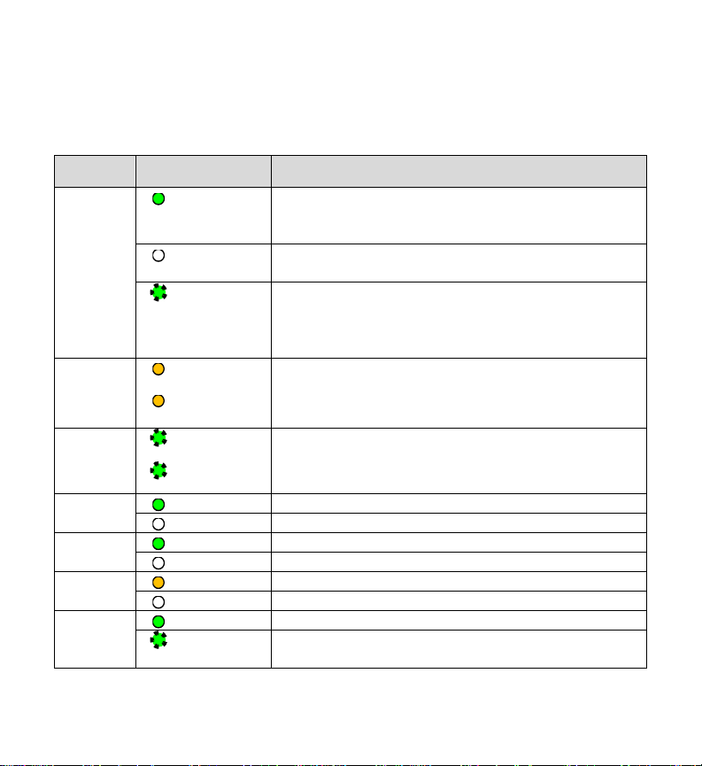
13 PACSystems* RX3i 1GHz 64MB CPU w/Ethernet Quick Start Guide GFK-2941E
Page 15

On
Blinking
Off
CPE330 LED
LED State
Operating State
CPU OK
On Amber
Normal mode. (Compatible with CPU320)
FORCE
On Amber
RUN
Off
RDSD
On Red
OUT EN
Off
SYS FLT
On Red
CPU OK
On Amber
CRU320 Compatibility mode.
FORCE
On Amber
RUN
On Red
RDSD
Off
OUT EN
Off
SYS FLT
On Red
CPU Status Indicators
4. To toggle the compatibility setting, press the RDSD DNLD button. The
compatibility indication will toggle between the Normal (CPU320) and
CRU320 compatibility patterns each time the RDSD DNLD button is pressed.
5. When the desired compatibility setting is displayed, press the RDSD UPLD
button to save the setting and allow the CPE330 to continue its normal
startup procedures with the new setting. The setting is maintained over a
power cycle and firmware upgrade.
GFK-2941E May 2016 14
Page 16

Note that with versions of PME that do not have native CPE330 support, only CPU320
projects can be stored to CPE330s that are in Normal (CPU320) compatibility mode
and only CRU320 projects can be stored to CPE330s that are in CRU320 compatibility
mode. Users of a CPE330 with PME version 8.60 SIM 8 or later do not need to change
this compatibility setting if the project is converted to a CPE330 application. By
factory default, the CPE330 is set to Normal (CPU320) compatibility mode.
Migration of CPU315 applications to the CPE330 is possible with no upgrade to PME
by converting them to a CPU320 application and storing the project to the CPE330.
Note that CPE330s with firmware versions 8.45 through 8.60 support compatibility
with the CPU320 and CPU315 only. The compatibility setting using the RDSD buttons
is not supported for these firmware versions. Beginning with firmware version 8.70,
CPE330s support compatibility with the CPU320, CPU315, and CRU320 using the
RDSD buttons to set the compatibility mode.
The compatibility setting may be viewed at any time using the CPE330’s firmware
update web page. When the compatibility setting is Normal (CPU320), the catalog
number is listed as “IC695CPE330”. When the compatibility setting is CRU320
compatibility mode, the catalog number is listed as “IC695CPE330 CRU320
Compatibility Mode”.
15 PACSystems* RX3i 1GHz 64MB CPU w/Ethernet Quick Start Guide GFK-2941E
Page 17

3.6. Removable Data Storage Device (RDSD)
The CPE330 user program and/or memory contents may be saved to a USB device
via the RDSD UPLD pushbutton or loaded into the CPU from a USB device via the
RDSD DNLD pushbutton. Similarly, data can be selected and saved. In this way, an
application may be cloned and copied from one device to another.
4. Periodic Maintenance
4.1. Real-Time Clock Battery
The CPE330 is shipped with a real time clock (RTC) battery
installed (see Figure 3). Over time, this battery will need to be
replaced. No action is required during initial installation.
Should the RTC battery fail, the CPU date and time will be
reset to 12:00 AM, 01-01-2011 at start-up. The CPU operates
normally with a failed or missing RTC battery; however, the
initial CPU time-of-day (TOD) clock information will be
incorrect.
There are no diagnostics or indicators to monitor RTC battery
status. The RTC battery has an estimated life of 5 years and
must be replaced every 5 years on a periodic maintenance
schedule.
For complete procedure, refer to Replacement of Real-Time
Clock Battery on CPE330 in PACSystems RX3i and RX7i CPU
Reference Manual, GFK-2222V or later.
4.2. Spare Parts
IC690ACC001 Battery, Lithium BR2032-BA Coin Cell 3V 190mAh -40°C to +85°C
Figure 3: RTC
Battery
GFK-2941E May 2016 16
Page 18

5. Additional Information
Proficy Logic Developer-PLC Getting Started
GFK-1918
PACSystems RX3i & RX7i CPU Reference Manual
GFK-2222
PACSystems RX3i & RX7i TCP/IP Ethernet Communications User’s Manual
GFK-2224
PACSystems TCP/IP Ethernet Communications Station Manager Manual
GFK-2225
PACSystems RX3i System Manual
GFK-2314
PACSystems RXi, RX3i, and RX7i Controller Secure Deployment Guide
GFK-2830
PACSystems RX3i Energy Pack IC695ACC402 Quick Start Guide
GFK-2939
PACSystems RX3i IC695CPE330 CPU Important Product Information
GFK-2942
PACSystems RX3i and RX7i CPU Programmer’s Reference Manual
GFK-2950
PACSystems HART Pass Through User Manual
GFK-2929
PACSystems Hot Standby CPU Redundancy User Manual
GFK-2308
PACSystems RX3i PROFINET IO Controller User Manual
GFK-2571
PROFINET I/O Devices Secure Deployment Guide
GFK-2904
GE’s Automation & Controls
All other trademarks are property of their respective holders
GFK-2941E
g
User manuals, product updates and other information sources are available on the
Support website, www.geautomation.com
Contact Information
Americas: 1-800-433-2682 or 1-434-978-5100
Global regional phone numbers are available on our web site
www.geautomation.com
Copyright © 2014-2016 General Electric Company. All Rights Reserved.
* Trademark of General Electric Company and/or its subsidiaries.
under Controllers and IO, RX3i Controllers.
 Loading...