

Page 1

GE
Intelligent Platforms
Programmable Control Products
PACSystems*
RX3i Energy Pack
IC695ACC402
Quick Start Guide
GFK-2939
March 2015
Page 2

Contents
1. Overview .............................................................................. 1
2. Hardware Installation ................................................... 3
Mounting the Energy Pack on a DIN Rail ................. 3
Mounting the Energy Pack Directly on a Panel .... 4
Installation Location ........................................................... 4
3. Cable Connections ......................................................... 6
Connecting to the Energy Pack .................................... 6
Connecting the Energy Pack to the Controller ..... 6
4. Grounding ........................................................................... 7
5. Power-Up ............................................................................ 8
6. LED Indications ................................................................. 9
7. Firmware Updates ....................................................... 10
LED Indications for Firmware Updates .................. 10
8. Replacing the Cap Pack Module .......................... 11
9. Additional Information .............................................. 13
i PACSystems* RX3i Energy Pack IC695ACC402 Quick Start Guide GFK-2939
Page 3
1. Overview
The ACC402 Energy
Pack is used
exclusively with the
CPE330 RX3i CPU. It
preserves user
memory in the
Controller during
power fluctuations
or outages.
If system power is
lost, the Energy Pack
maintains power
long enough for the
connected CPE330
to write its user
memory contents to
non-volatile
memory. When
system power is
restored, the user
memory is restored
if the CPE330 is
configured to power
up from RAM.
GFK-2939 March 2015 1
Page 4

The ACC402 Energy Pack is connected to the
IC695ACC402
CPE330-compatible Energy Pack.
Includes Base, Cap Pack module, CPU
connecting cable & ground strap.
IC695ACC412
Replacement Cap Pack module.
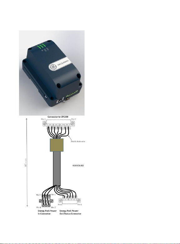
IC695CBL002
Replacement 1m (36”) CPU connecting
cable.
IC695CPE330 CPU via a dedicated cable IC695CBL002
(shown above). This arrangement allows the Energy Pack
to source power from the RX3i backplane in order to
charge its circuitry. The cable also allows the CPU to
monitor the status of the Energy Pack. Upon loss of
backplane power, the CPU automatically switches over
to the Energy Pack power source, ensuring an orderly
power-down sequence.
Ordering Information
2 PACSystems* RX3i Energy Pack IC695ACC402 Quick Start Guide GFK-2939
Page 5
2. Hardware Installation
The ACC402 Energy Pack may be mounted on a
standard EN50022 DIN rail or directly on an equipment
panel. It is designed to be mounted adjacent to the
CPE330 Controller and connected to the Controller using
the 1m cable provided (IC695CBL002).
Heat dissipation: A minimum clearance of 25mm
(1 inch) needs to be provided on all four sides of the unit
(right, left, top and bottom).
Mounting the Energy Pack on a DIN Rail
The Energy Pack snaps easily onto the DIN rail. No tools
are required.
GFK-2939 March 2015 3
Page 6

Mounting the Energy Pack Directly on a Panel
CAUTION
Over tightening the mounting screws could
crack the plastic housing.
Recommended fasteners:
The baseplate accommodates four M4-0.7 machine
screws (8-36 UNF). Minimum length of 25mm (or 1”) is
recommended. Secure with matching nuts.
Installation Location
This product is intended for use with the RX3i system. Its
components are considered open equipment (having live
electrical parts that may be accessible to users) and
must be installed in an ultimate enclosure that is
manufactured to provide safety. At a minimum, the
enclosure shall provide a degree of protection against
solid objects as small as 12mm (e.g. fingers). This
equates to a NEMA/UL Type 1 enclosure or an IEC60529
IP20 rating providing at least a pollution degree 2
environment. For details about installing RX3i rack
systems, refer to PACSystems* RX3i System Manual,
GFK-2314.
If you need technical help, contact Technical Support.
For phone numbers and email addresses, see the back
cover of this Guide.
4 PACSystems* RX3i Energy Pack IC695ACC402 Quick Start Guide GFK-2939
Page 7

Installation in Hazardous Areas
The following information is for products bearing the UL
marking for Hazardous Areas or ATEX marking for
explosive atmospheres:
CLASS 1 DIVISION 2 GROUPS ABCD
This equipment is an open-type device and is
meant to be installed in an enclosure suitable
for the environment that is only accessible with
the use of a tool.
Suitable for use in Class I, Division 2, Groups A,
B, C and D Hazardous Locations, or
nonhazardous locations only.
Warning – EXPLOSION HAZARD -
SUBSTITUTION OF COMPONENTS MAY IMPAIR
SUITABILITY FOR CLASS I, DIVISION 2.
Warning – WHEN IN HAZARDOUS LOCATIONS,
TURN OFF POWER BEFORE REPLACING OR
WIRING MODULES; AND
ATEX Zone 2
This module must be mounted in an enclosure certified
in accordance with EN60079-15 for use in Zone 2, Group
IIC and rated IP54. The enclosure shall only be able to be
opened with the use of a tool.
GFK-2939 March 2015 5
Page 8

3. Cable Connections
Connecting to the Energy Pack
The two connectors on the ACC402 Energy Pack mate
with the corresponding two pre-wired pig-tailed
connectors of the IC695CBL002 cable assembly. Insert
each keyed connector as shown above and secure using
the captive screws provided.
Connecting the Energy Pack to the Controller
With power to the CPE330 Controller turned off, connect
the 7-pin keyed connector of the IC695CBL002 cable
assembly to the mating connector on the underside of
the IC695CPE330 and secure using the captive screws
provided.
6 PACSystems* RX3i Energy Pack IC695ACC402 Quick Start Guide GFK-2939
Page 9

4. Grounding
Proper grounding of this device is essential. The included
ground strap wire must be pressed onto the spade lug
connector on the left side of the ACC402. Cable assembly
IC695CBL002 ties all internal cable shield drains to this
ground.
The frame ground wiring used by both the CPE330 and
ACC402 must be connected to a central ground point.
The green and yellow ground strap wire (see figure
above), which attaches to the spade lug on the side of
the ACC402 base plate, must be connected to the central
ground point.
All ground wires from the host rack or panel must be as
short as possible and terminated at the same grounding
point.
GFK-2939 March 2015 7
Page 10

5. Power-Up
IN
STAT
OUT
When power is applied to the Energy Pack, the power-up
process goes through the following steps:
1. The IN LED turns on green.
2. The Energy Pack performs a self-
diagnostic test. If this test passes,
output power to the Controller is
turned on and the OUT LED turns on
(green).
3. Charging of the Cap Pack begins and
the STAT LED blinks green.
4. When charging of the Cap Pack is complete, the
STAT LED turns on solid green and the Energy Pack
signals to the controller that it can start run-time
operation. The Controller will not start running its
application until the Energy Pack signals that it is
fully charged.
5. If the Energy Pack is faulty or is not communicating,
the Controller will commence operations after a
timeout period (90 sec).
8 PACSystems* RX3i Energy Pack IC695ACC402 Quick Start Guide GFK-2939
Page 11

LED
State
Energy Pack Status
IN
Green,
solid
Input power is applied and within the
specified range.
Red,
solid
Input power is outside the specified
range.
Off
Input power is not applied.
STAT
Green,
blinking
Charging of Cap Pack is in progress.
No fault exists.
Green,
solid
Cap Pack is fully charged and no fault
exists.
Amber,
blinking
Cap Pack is nearing end-of-life. The
Cap Pack must be replaced soon.
Backup is still guaranteed.
Red,
blinking
Internal fault: Cycle power to the
Energy Pack. If this does not clear the
fault, contact Technical Support and
replace the Energy Pack.
Red,
solid
Cap Pack has reached end-of-life.
Replace the Cap Pack. Backup is not
guaranteed.
Off
No power applied.
OUT
Green,
solid
Output power is within the specified
range.
Red,
solid
Output power is present but is
outside the specified range.
Off
Output power is not present.
6. LED Indications
GFK-2939 March 2015 9
Page 12

7. Firmware Updates
Firmware Update Mode
All three LEDs blink green
Failed to Load Firmware
All three LEDs blink red
The firmware for the Energy Pack is automatically
updated by the Controller. At power-up, the Controller
checks the version of Energy Pack firmware to verify
compatibility with the Controller firmware. If an update is
needed, the Controller performs it automatically.
LED Indications for Firmware Updates
10 PACSystems* RX3i Energy Pack IC695ACC402 Quick Start Guide GFK-2939
Page 13

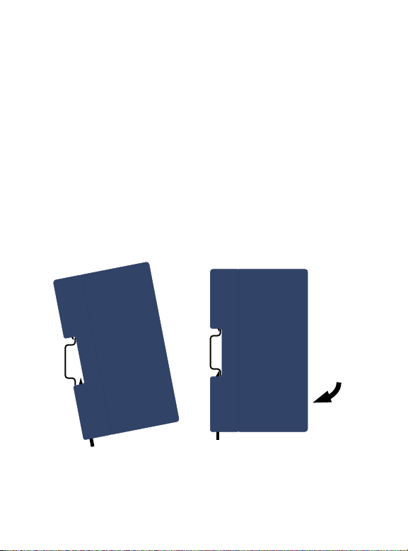
8. Replacing the Cap Pack Module
CAUTION
When hot swapping Cap Packs, do not cycle
power until the new Cap Pack is fully charged
and operational. Cycling power before the
STAT LED is solid green can result in
Controller memory not being preserved. Do
not hot remove/insert the Cap Pack during
the firmware update process
CAUTION
Over tightening the mounting screws could
crack the plastic housing.
The status of the Energy Pack is provided at %S0014
(#PLC_BAT) and %SA0011 (#LOW_BAT). User programs
should monitor these status bits in order to alert for
maintenance conditions. Refer to PACSystems RX7i and
RX3i CPU Reference Manual, GFK-2222V or later.
The Cap Pack may be removed and replaced while
power is applied to the Energy Pack (hot swapped.)
1. Loosen the four screws on the Cap Pack and
carefully pull the Cap Pack off the base.
2. Install the new Cap Pack on the base, first engaging
the module-to-base connectors and then pressing
the Cap Pack into place.
GFK-2939 March 2015 11
Page 14

3. Use the four screws provided to secure the Cap Pack
to the base.
4. When the Cap Pack is first inserted, the STAT LED
blinks green while the Cap Pack is charging. Do not
remove power to the Energy Pack while the Cap Pack
is charging because this could result in Controller
memory not being preserved.
Following a hot swap insertion, the Cap Pack will
draw only a small current in order not to disrupt
overall power requirements. As a result, it may take
up to 10 mins to reach its full charge. This is normal.
The Energy Pack LEDs and the associated status bits
indicate when charging is complete and the Energy
Pack is ready to support backup.
5. To remove a Failed Battery fault and clear the
associated status bits, clear the Controller
Fault Table.
For details on user programming based on status bit
operation, refer to the PACSystems* RX7i and RX3i
CPU Programmer’s Reference Manual, GFK-2950.
12 PACSystems* RX3i Energy Pack IC695ACC402 Quick Start Guide GFK-2939
Page 15

9. Additional Information
PACSystems* RX3i Power Sync and Measurement System,
GFK-2748
PACSystems* RX3i 1GHz 64MB CPU w/Ethernet Quick
Start Guide, GFK-2941A
PACSystems* Controllers: Battery and Energy Pack
Manual, GFK-2741C or later
PACSystems* RX3i Energy Pack IC695ACC402 Important
Product Information, GFK-2940
PACSystems* RX7i and RX3i CPU Reference Manual,
GFK-2222V or later
PACSystems* RX3i System Manual, GFK-2314
PACSystems* RX7i and RX3i CPU Programmer’s
Reference Manual, GFK-2950
For user manuals, product updates and other
information go to the Support website,
http://www.ge-ip.com/support and refer to Controllers
and IO, RX3i Controllers.
GFK-2939 March 2015 13
Page 16

GE Intelligent Platforms
Contact Information
Americas: 1-800-433-2682 or 1-434-978-5100
Global regional phone numbers are available on our web site
www.ge-ip.com
©2015 General Electric Company. All Rights Reserved
*Trademark of GE Intelligent Platforms, Inc.
All other brands or names are property of their respective holders
GFK-2939
 Loading...