

Page 1
TechBook
in.yj
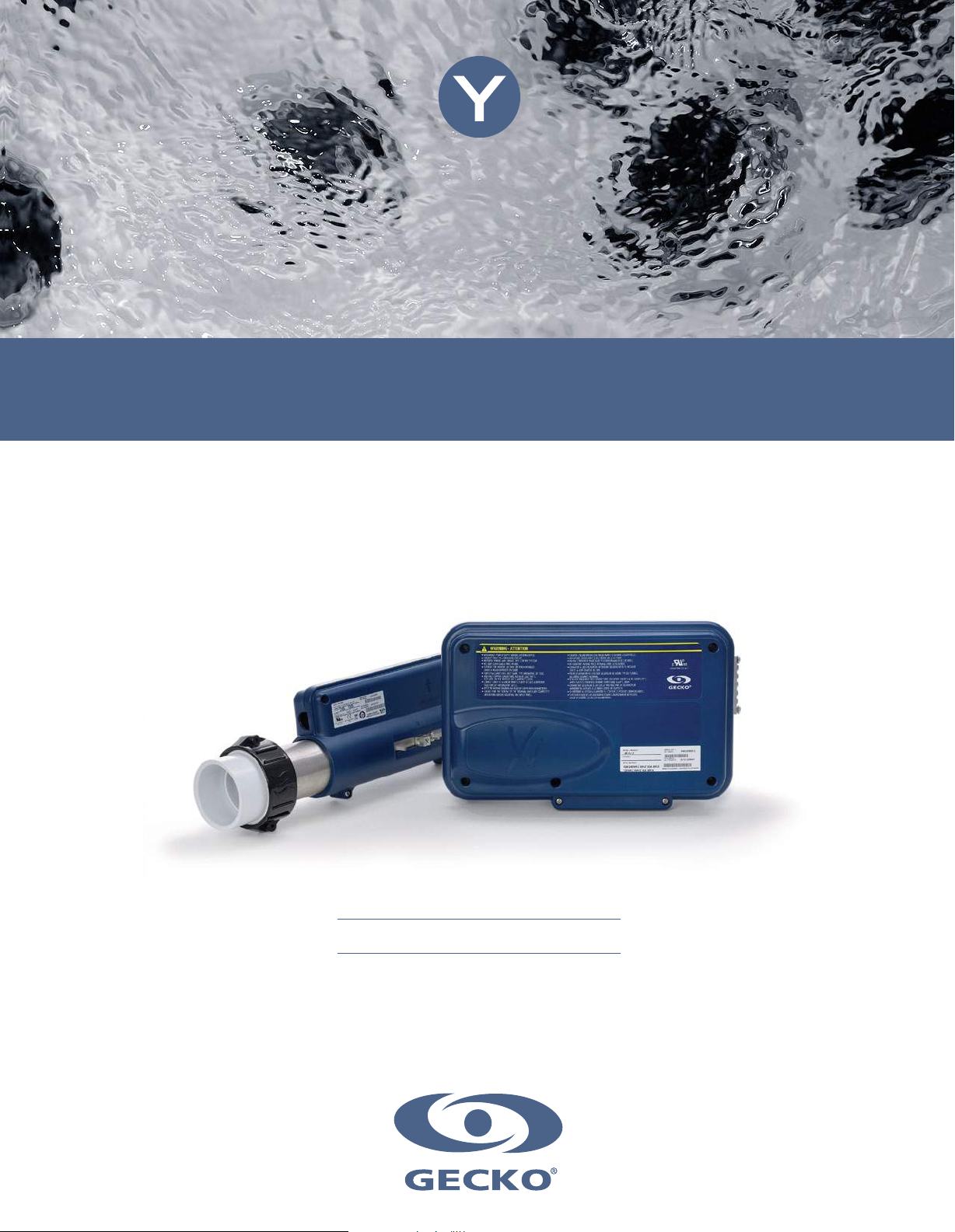
Small package, zero compromise!
Full-size heater
Field convertible 240 V to 120 V
Easy spa integration
Page 2

Page 3

Table of contents
Warnings ......................................................................................................................................................................... 2
Introduction ..................................................................................................................................................................... 3
Features .......................................................................................................................................................................... 4
Overview
- in.yj dimensions .................................................................................................................................................. 5
- heat.wav dimensions .......................................................................................................................................... 5
Installation
- in.yj positioning ................................................................................................................................................... 6
- in.yj installation procedure with standard wall mounting bracket(s) .................................................................... 6
- in.yj installation procedure with wall mounting Z-bracket(s) ............................................................................... 7
- heat.wav installation (not applicable on in.yj-re models) ..................................................................................... 7
- Keypad installation ............................................................................................................................................. 7
Connections
- Preparation ......................................................................................................................................................... 8
- Connecting the main keypad and the light socket cable .................................................................................... 8
- Connecting the heat.wav (not applicable on in.yj-re models) .............................................................................. 9
- Connecting high voltage accessories: North American model in.yj ................................................................... 10
- Connecting high voltage accessories: European, Australian, New Zealand model in.yj-ce ............................... 11
- Connecting high voltage accessories: North American heat recovery model in.yj-re ........................................ 12
- Connecting the probe (regulation and overheat captor) on the heat recovery model in.yj-re ............................ 13
- Completing the installation ............................................................................................................................... 14
Electrical wiring
- Electrical wiring: all models ............................................................................................................................... 15
- Electrical wiring: North Amercian model ........................................................................................................... 16
- Electrical wiring: CE/AUS/NZS models .............................................................................................................. 17
Controler power up ........................................................................................................................................................ 18
Compatible keypads ...................................................................................................................................................... 19
Troubleshooting ............................................................................................................................................................. 20
Specifications ................................................................................................................................................................ 21
1
Page 4
Warnings3Introduction
WARNINGS:
Before installing or connecting the unit, please read the following.
* FOR UNITS FOR USE IN OTHER THAN SINGLE-FAMILY DWELLINGS, A CLEARLY LABELED EMERGENCY SWITCH SHALL
BE PROVIDED AS PART OF THE INSTALLATION. THE SWITCH SHALL BE READILY ACCESSIBLE TO THE OCCUPANTS AND
SHALL BE INSTALLED AT LEAST 5' (1.52 M) AWAY, ADJACENT TO, AND WITHIN SIGHT OF THE UNIT.
* ANY DAMAGED CABLE MUST BE IMMEDIATELY REPLACED BY QUALIFIED PERSONNEL.
* TURN POWER OFF BEFORE SERVICING OR MODIFYING ANY CABLE CONNECTIONS IN THIS UNIT.
* TO PREVENT ELECTRIC SHOCK HAZARD AND/OR WATER DAMAGE TO THIS CONTROL,
ALL UNUSED BUSHING CONDUITS MUST BE PLUGGED WITH THE ATTACHED NIPPLE.
* THIS CONTROLLER MUST NOT BE INSTALLED IN PROXIMITY OF HIGHLY FLAMMABLE MATERIALS.
* LOW SUPPLY VOLTAGE OR IMPROPER WIRING MAY CAUSE DAMAGE TO THIS CONTROL SYSTEM.
READ AND FOLLOW ALL WIRING INSTRUCTIONS WHEN CONNECTING TO POWER SUPPLY.
* THIS PACK CONTAINS NO USER SERVICEABLE PARTS. CONTACT AN AUTHORIZED SERVICE CENTER
FOR SERVICE.
* ALL CONNECTIONS MUST BE MADE BY A QUALIFIED ELECTRICIAN IN ACCORDANCE WITH
THE NATIONAL ELECTRICAL CODE AND ANY STATE, PROVINCIAL OR LOCAL ELECTRICAL CODE
IN EFFECT AT THE TIME OF THE INSTALLATION.
* PRODUCT MUST BE DISPOSED OF SEPARATELY IN ACCORDANCE WITH LOCAL WASTE DISPOSAL LEGISLATION.
* THIS APPLIANCE IS NOT INTENDED FOR USE BY PERSONS (INCLUDING CHILDREN) WITH REDUCED PHYSICAL,
SENSORY OR MENTAL CAPABILITIES, OR LACK OF EXPERIENCE AND KNOWLEDGE, UNLESS THEY HAVE BEEN GIVEN
SUPERVISION OR INSTRUCTION CONCERNING USE OF THE APPLIANCE BY A PERSON RESPONSIBLE FOR THEIR
SAFETY.
* CHILDREN SHOULD BE SUPERVISED TO ENSURE THAT THEY DO NOT PLAY WITH THE APPLIANCE.
* MEANS FOR DISCONNECTION MUST BE INCORPORATED IN THE FIXED WIRING IN ACCORDANCE WITH
THE WIRING RULES.
* CAUTION: IN ORDER TO AVOID A HAZARD DUE TO INADVERTENT RESETTING OF THE THERMAL CUT-OUT, THIS
APPLIANCE MUST NOT BE SUPPLIED THROUGH AN EXTERNAL SWITCHING DEVICE, SUCH AS A TIMER,
OR CONNECTED TO A CIRCUIT THAT IS REGULARLY SWITCHED ON AND OFF BY THE UTILITY.
* PARTS CONTAINING LIVE PARTS, EXCEPT PARTS SUPPLIED WITH SAFETY EXTRA-LOW VOLTAGE NOT EXCEEDING 12
V, MUST BE INACCESSIBLE TO A PERSON IN THE BATH OR SPA.
* PARTS INCORPORATING ELECTRICAL COMPONENTS, EXCEPT REMOTE CONTROL DEVICES, MUST BE LOCATED OR
FIXED SO THAT THEY CANNOT FALL INTO THE BATH OR SPA.
* PARTS ARE TO BE INSTALLED IN THE CORRECT ZONE AND EQUIPOTENTIAL BONDING CARRIED-OUT IN
ACCORDANCE WITH THE WIRING RULES.
*CLEARANCE AND MINIMUM DISTANCE BETWEEN THE VARIOUS PARTS OF THE APPLIANCE AND THE SURROUNDING
STRUCTURE ARE NOT SPECIFIED AS LONG AS THEY ARE SUFFICIENT SO THAT THE AMBIENT TEMPERATURE
AROUND THE CONTROLLER DOES NOT EXCEED 60°C
Aeware®, Gecko®, and their respective logos are Registered Trademarks of Gecko Alliance Group.
in.yj™, in.keys™, in.touch™, in.k200™, in.k400™, in.k450™, in.k600™, K-19™, K-35™, K-8™, in.k1000™, in.k800™, in.k500™,
in.k300™, in.flo™, in.put™, in.seal™, in.link™, in.t.cip™, in.stik™, heat.wav™, Y Series™, and their respective logos are Trademarks
of Gecko Alliance Group.
All other product or company names that may be mentioned in this publication are tradenames, trademarks or registered trademarks of
their respective owners.
2
Page 5
in.yj
small package, zero compromise
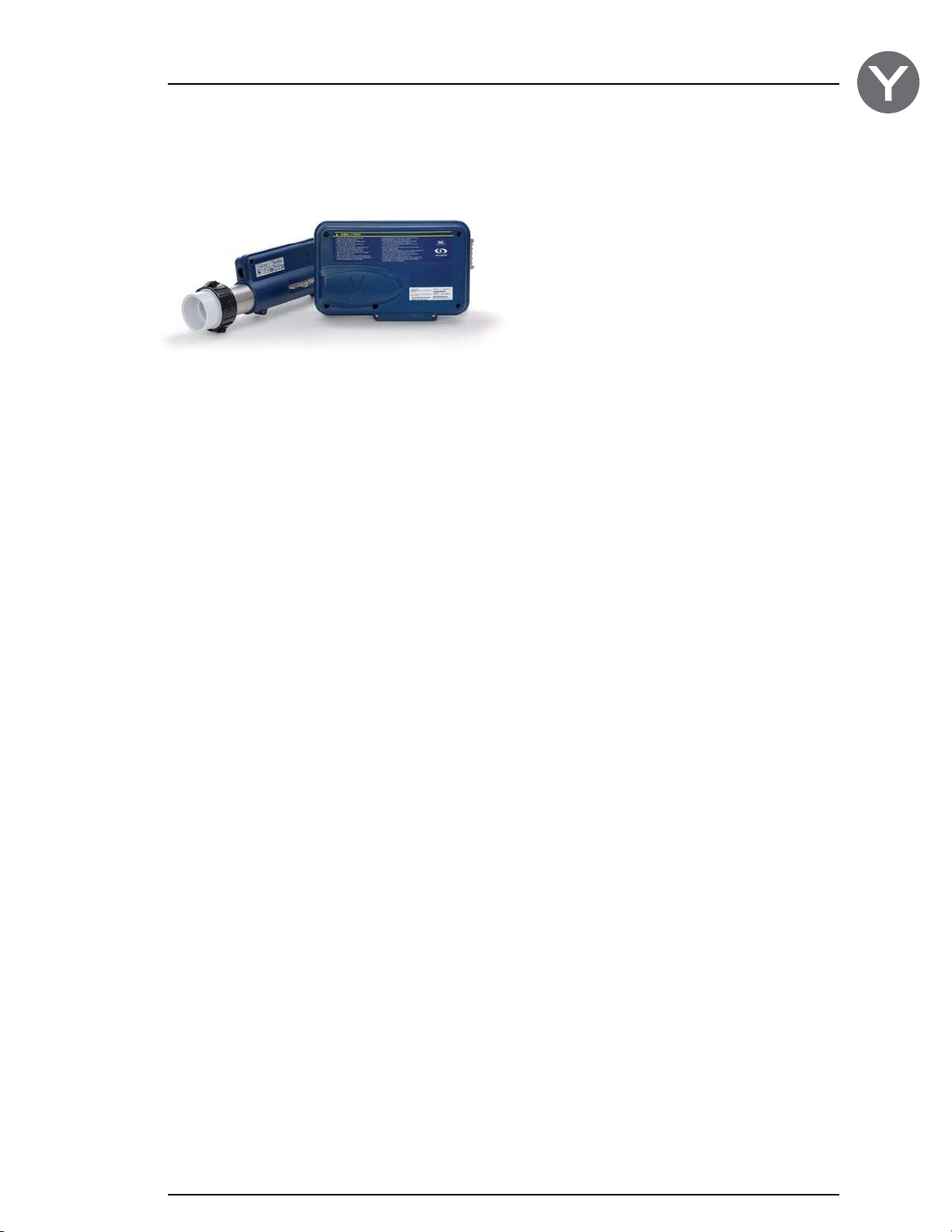
Say hello to the newest member of the Y Series!
The in.yj’s size makes it easy to install in your small
footprint spa, without losing out on functionality and
options.
It also offers total heating flexibility. The pack can be
bought on its own for use in a heat recovery system
(in.yj-re), or bundled with the compact heat.wav-yj heater
for efficient heating in any space.
Like all Y Series packs, the in.yj is compatible with our
in.k series of keypads. And what's more, the Y Series also
takes into account future compatibility, so you can have
peace of mind knowing that you can enjoy the Y Series for
years to come.
Page 6

Features
The Y Series systems boast a long list of technical features. Each of them contributes to bringing the most advanced
solutions available to Y Series equipped spa owners:
in.seal
watertight protection
In.seal provides an extra level of protection against
water infiltration. Connectors and power box are
designed to be watertight so that no water can
be in direct contact with electrical components
(IPX5).
in.stik
automated software upload
The in.stik is a pen drive with an in.link connector
very similar to a USB memory stick. It connects
to the spa pack and contains data to program or
configure its system. The system executes the
data upload automatically.
in.touch
you're always in touch with your relaxation
All Y Series packs support the in.touch WiFi
interface, allowing you to use your favorite iOS
device to communicate with your spa.
in.flo
dry-fire protection
in.flo is an all-electronic dry-fire protection that is
built in to the remote heat.wav heater. The in.flo
eliminates the burden of adjustments, calibrations
and failures associated to usual water flow sensors.
in.t.cip
water temperature algorithm
in.t.cip is an intelligent water temperature refresh
algorithm that calculates optimal time to start
pumps and get water temperature readings.
In.t.cip continuously readjusts the heater start
time (according to exterior temperature).
in.link
ingenious plugs and connectors
The Y Series is only compatible with the lowvoltage family of in.link connectors, such as
those used by keypads and similar low-voltage
accessories.
in.put
input terminal block
In.put was designed to ease wire insertion
(up to # 6 AWG) and connections. Tighter input
connection reduces heat generated for increased
component lifetime.
4
Page 7
Overview
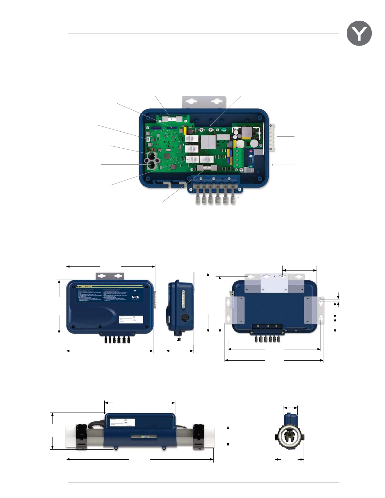
Probe connectors
(heat.wav's low voltage
cable or regulation probe
and overheat captor
model-re)
Light output (12 V DC)
Communication link
(in.touch or in.stik)
Main keypad
connector
Power output drivers
in.yj dimensions
Front view
12.14"
(308 mm)
Pump 2 fuse (Available
only with the in.yj-3)
Pump 1 and
accessory fuse
Side view
heat.wav power
connection
5 possible positions for the bracket
Rear view
Bonding lugs
Main power entry
connection
Watertight strain
relief system
4.79"
(122 mm)
4.94"
(125 mm)
7.33 "
(186 mm)
heat.wav dimensions
11.83"
(301 mm)
Front view
9.45"
(240 mm)
19.58"
(497 mm)
3.78"
(96 mm)
8.29"
(211 mm)
7.86"
(200 mm)
2.77"
(70 mm)
12.89"
(327 mm)
13.75"
(349 mm)
Side view
1.88"
(48 mm)
3.92"
(100 mm)
2.25"
2.04"
0.40"
(10 mm)
(57 mm)
(52 mm)
Note: Shown with optional wall mouting brackets (see Installation).
5
Page 8
Installation
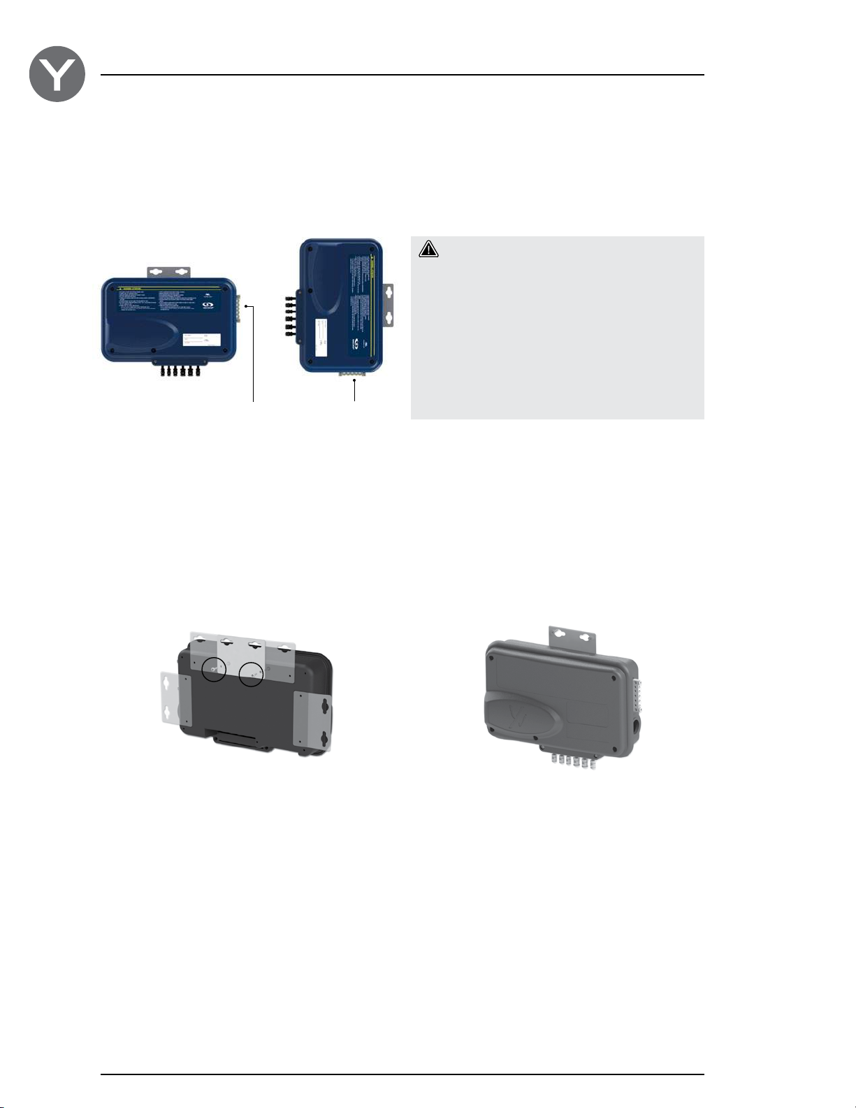
in.yj positioning
To prevent water from getting inside 2 positions are allowed.
2
1
Bonding lugBonding lug
Warning!
Beware of the application of some products
commonly used against corrosion (such as
WD-40 family products) as they could damage
the pack, due to a negative chemical reaction
between some industrial oils and its plastic
enclosure. Any other materials which may
come in contact with the enclosure must be
carefully evaluated under end use conditions for
compatibility.
Two types of brackets can be used to secure the pack:
in.yj installation procedure with standard wall mounting bracket(s)
2 3 4
1
5
Flat aluminum brackets are designed for back wall
mounting. There are 5 possible positions you can use.
Multiple brackets can be used if extra support is needed.
Fasten the mounting bracket(s) to the back of the pack
with the supplied screws.
Part number:
Wall mount bracket kit 100 pcs - 9920-101474
(with 200 screws to attach to pack)
Using the brackets, fasten pack to 2" x 4" or 2" x 6" timber
wall studs under the spa. We recommend using #10 self
threading screws with pan or truss heads and washers
1/2" OD x 1/16” (12 mm OD x 1.5 mm).
Note: The spa pack must be installed at least 4" (100 mm) above
potential flood level. If floor is on ground level, pack should be
raised at least 4" (100 mm).
6
Page 9
Installation
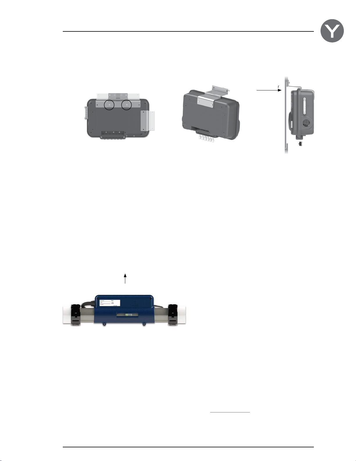
in.yj installation procedure with wall mounting Z-bracket(s)
1 32
4
The aluminum Z-bracket is designed for flush-mounting
the pack directly on the edge of the access door frame
of your spa. It can be mounted to the pack in one of
4 positions for greater flexibility.
Fasten the mounting bracket(s) to the back of the pack
with the supplied screws.
Part number:
Z-bracket in.yj kit 100 pcs - 9920-101478
(with 200 screws to attach to pack)
Access door
Depending on your specific needs, you can fasten with
two #10-24 screws of your choice.
Note: The spa pack must be installed at least 4" (100 mm) above
potential flood level. If floor is on ground level, pack should be
raised at least 4" (100 mm).
heat.wav installation (not applicable on in.yj-re models)
This side up
The heat.wav heating element must be installed in the
return circuit of the main pump (pressure side).
Keypad installation
For detailed installation instructions and a drilling template, refer to the compatible keypad section and select your
keypad to be redirected to the corresponding techbook.
7
Page 10
Connections
Preparation
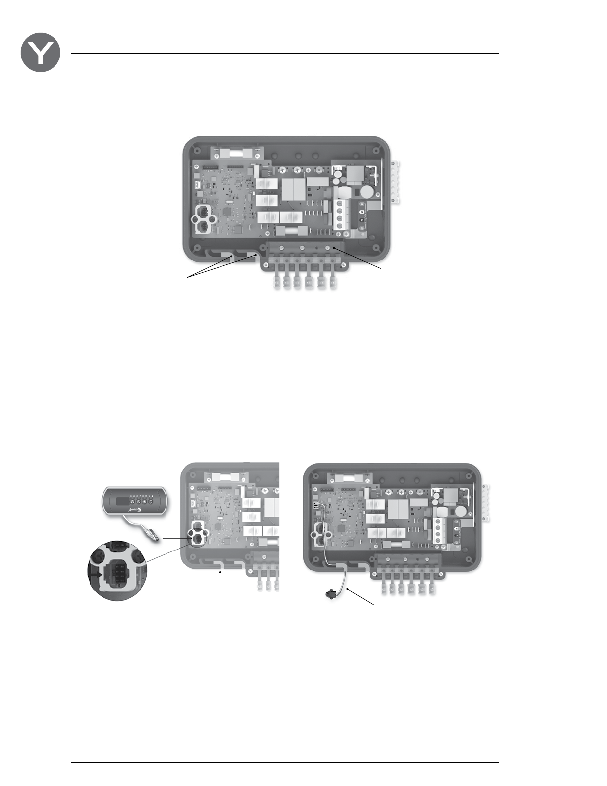
Foam gasket
Molded strain relief channels
Strain relief bracket
Remove the cover screws from the front of the pack with a Phillips screw driver.
Remove and put aside the strain relief bracket and the foam gasket located in the molded strain relief channels.
Connecting the main keypad and the light socket cable
Note: always shut power down before connecting an accessory to the pack.
Keypad
Keypad conduit
Connect the main keypad
as indicated here.
To connect the keypad, insert the in.link connector into
the appropriate keypad connector (as illustrated).
To connect the light socket cable, insert the MTA
connector into the 12 V DC light output connector P33
Light socket cable
(as illustrated).
Part number:
Light socket cable - 9920-400489
Route the low voltage cables through the molded strain relief channels on the bottom of the spa pack.
8
Page 11
Connexions
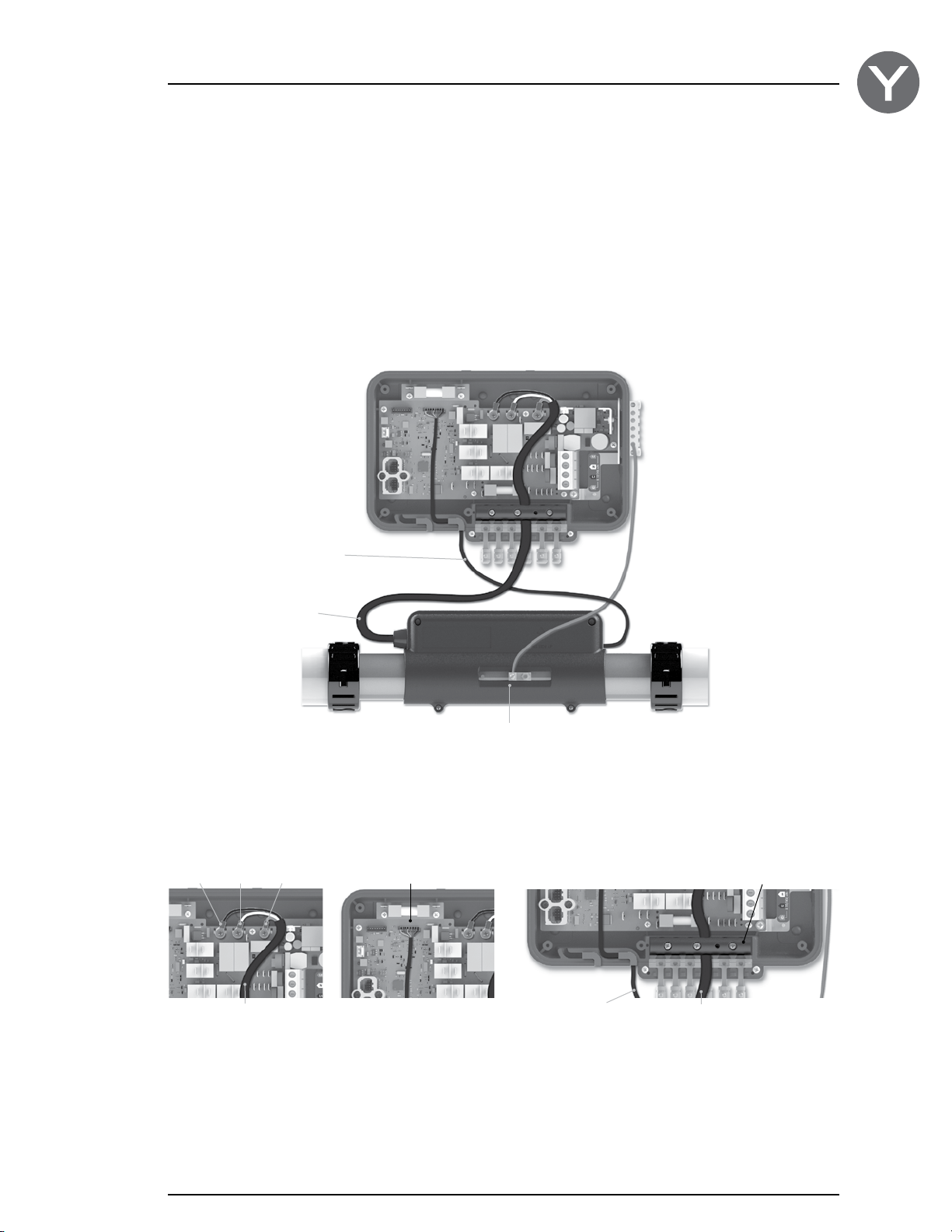
Connecting the heat.wav (not applicable on in.yj-re models)
The in.yj should be paired with a high performance
heat.wav heater.
Part numbers:
1,3 kW heat.wav - 0613-421004
2 kW heat.wav - 0613-421002
3 kW heat.wav - 0613-421003
4 kW heat.wav - 0613-421001
heat.wav
low voltage cable
heat.wav
power cable
heat.wav specification summary:
• in.flointegrateddry-fireprotection
• Supports120Vor240V
• Protectedbyexternalbreaker(notfused)*
• Incoloy®heaterelement
*Note: CE/AUS/NZS models are 230-240 V only,
and are fuse protected.
heat.wav bonding lug
Note: always shut power down before connecting an accessory to the pack.
Connect a solid copper conductor (not smaller than 8 AWG) between the bonding lugs on the side of the spa pack
and the bonding lug at the front of the heat.wav. The bonding conductor should be routed close to the contour of the
equipment to reduce the risk of damage during servicing.
Black White Green
heat.wav power cable
Connect the colored wires
black = P3
white = P4
green = P5
Note: Do not over tighten
screws (torque to 18 in. lb max
(2.0N.m.) and use of a tool up
to 500 rpm max)
Probe connector
(heat.wav's low voltage cable)
To connect the heat.wav
low voltage cable, insert
the JST into the probe
connector (P1).
Low voltage cable Power cable
Route the low voltage cable
through one of the molded
strain relief channels on
the bottom of the spa pack.
Strain relief bracket
Remove the small rubber
stopper. Route the power
cable through one of the
openings for 12-3 cable
size (as illustrated on
page 14).
9
Page 12
Connections
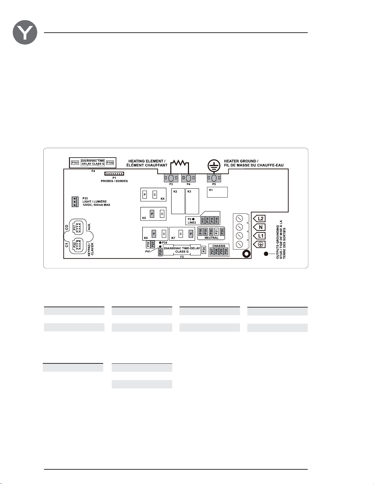
Connecting high voltage accessories: North American model in.yj
Wires to connect high voltage accessories must have 0.25” quick-connect terminals.
These tabs require high-voltage accessories to have straight, non-insulated, female quick-connect terminals for all
connections, including ground. Depending on where the connections are made on the in.yj pack PCB, 120 V and 240 V
accessories are supported. Refer to the following tables for correct connections. Note that all female terminals must be
correctly and completely seated on the PCB tab for proper current ratings.
Make sure all accessories are linked to the bonding lug connector located on the side of the spa pack.
Direct output
Voltage 120 V 240 V
Green / ground P27 P27
Black / line P25 P25
White / common P18 P14
Light (12 V DC , 500mA)
Switch P33
Pump 1
Voltage 120 V 240 V
Green / ground P28 P28
Black / low speed K6-P K6-P
Red / high-speed K7-P K7-P
White / common P19 P15
Heat.wav-yj
Green / ground P5
Black / line P3
White / common P4
Pump 2 (in.yj-3 only)
Voltage 120 V 240 V
Green / ground P29 P29
Black / low speed K5-P K5-P
White / common P20 P16
Ozone
(Working with pump 1 low speed)
Voltage 120 V 240 V
Green / ground P30 P30
Black / line P23 P23
White / common P35 P37
10
This table shows typical connections. OEMs may have a different connection scheme.
Page 13
Connections
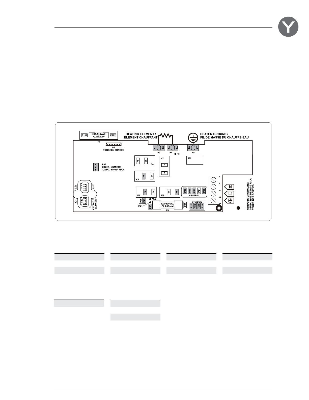
Connecting high voltage accessories: European, Australian, New Zealand model in.yj-ce
These tabs require high-voltage accessories to have straight, non-insulated, female quick-connect terminals for all
connections, including ground. Refer to the following tables for correct connections. Note that all female terminals must
be correctly and completely seated on the PCB tab for proper current ratings.
Make sure all accessories are linked to the bonding lug connector located on the side of the spa pack.
Direct output
Voltage 230 V
Ground P27
Line P25
Common P18
Light (12 V DC , 500mA)
Switch P33
Pump 1
Voltage 230 V
Ground P28
Low speed K6-P
High speed K7-P
Common P19
Heat.wav-yj
Green / ground P5
Black / line P3
White / common P4
Pump 2 (in.yj-3 only)
Voltage 230 V
Ground P29
Low speed K5-P
Common P20
Ozone
(Working with pump 1 low speed)
Voltage 230 V
Ground P30
Line P23
Common P35
This table shows typical connections. OEMs may have a different connection scheme.
11
Page 14
Connections
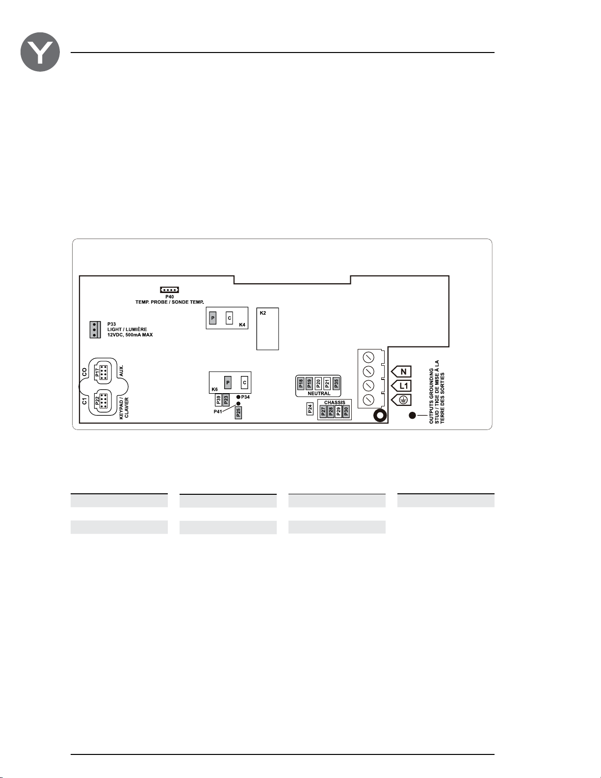
Connecting high voltage accessories: North American heat recovery model in.yj-re
These tabs require high-voltage accessories to have straight, non-insulated, female quick-connect terminals for all
connections, including ground. Refer to the following tables for correct connections. Note that all female terminals must
be correctly and completely seated on the PCB tab for proper current ratings.
Make sure all accessories are linked to the bonding lug connector located on the side of the spa pack.
Direct output
Voltage 120 V
Green / ground P27
Black / line P25
White / common P18
Pump 1
Voltage 120 V
Green / ground P28
Black / low speed K6-P
Red / high speed K4-P
White / common P19
Ozonateur
Voltage 120 V
Green / ground P30
Black / line P23
White / common P35
Light (12 V DC , 500mA)
Switch P33
12
This table shows typical connections. OEMs may have a different connection scheme.
Page 15
Connections
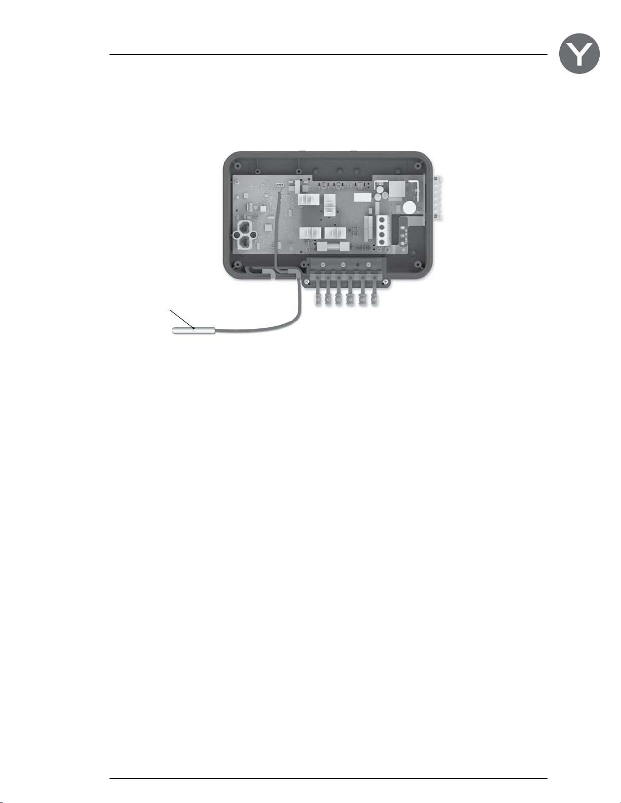
Connecting the probe (regulation and overheat captor) on the heat recovery model in.yj-re
Regulation probe and overheat
The probe assembly must be installed in the spa water in an area where water is not stagnant in order to optimize the
temperature regulation.
To connect the probe assembly cable, insert the JST into the probe connector (P40).
Route the probe assembly cable through one of the molded strain relief channels on the bottom of the spa pack.
Part number:
Regulation probe and overheat captor - 9920-401397
captor
13
Page 16
Connections
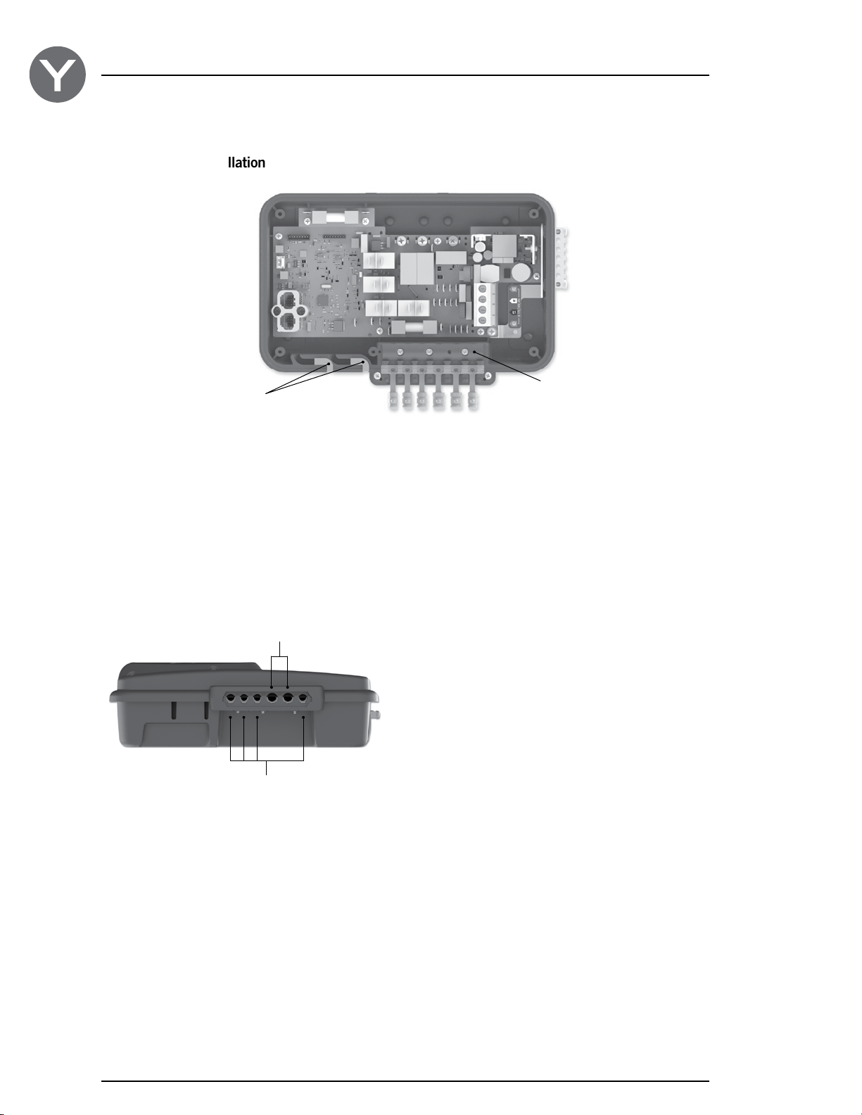
Completing the installation
Foam gasket
Molded strain relief channels
Once all low voltage cables are routed through the
molded strain relief on the bottom of the spa pack,
fill the remaining space with the foam gasket supplied.
For 12-3 /14-4/14-3
cable size
For 14-3 /18-3
cable size
Strain relief bracket
Once all high voltage accessories cables are routed
though one of the openings provided for this purpose at
the bottom of the spa pack, you can reinstall the strain
relief bracket.
Replace the cover. Do not over tighten cover screws
(torque to 8 in. lb max (0.9N.m.)
14
Output cable opening size
Page 17
Electrical wiring
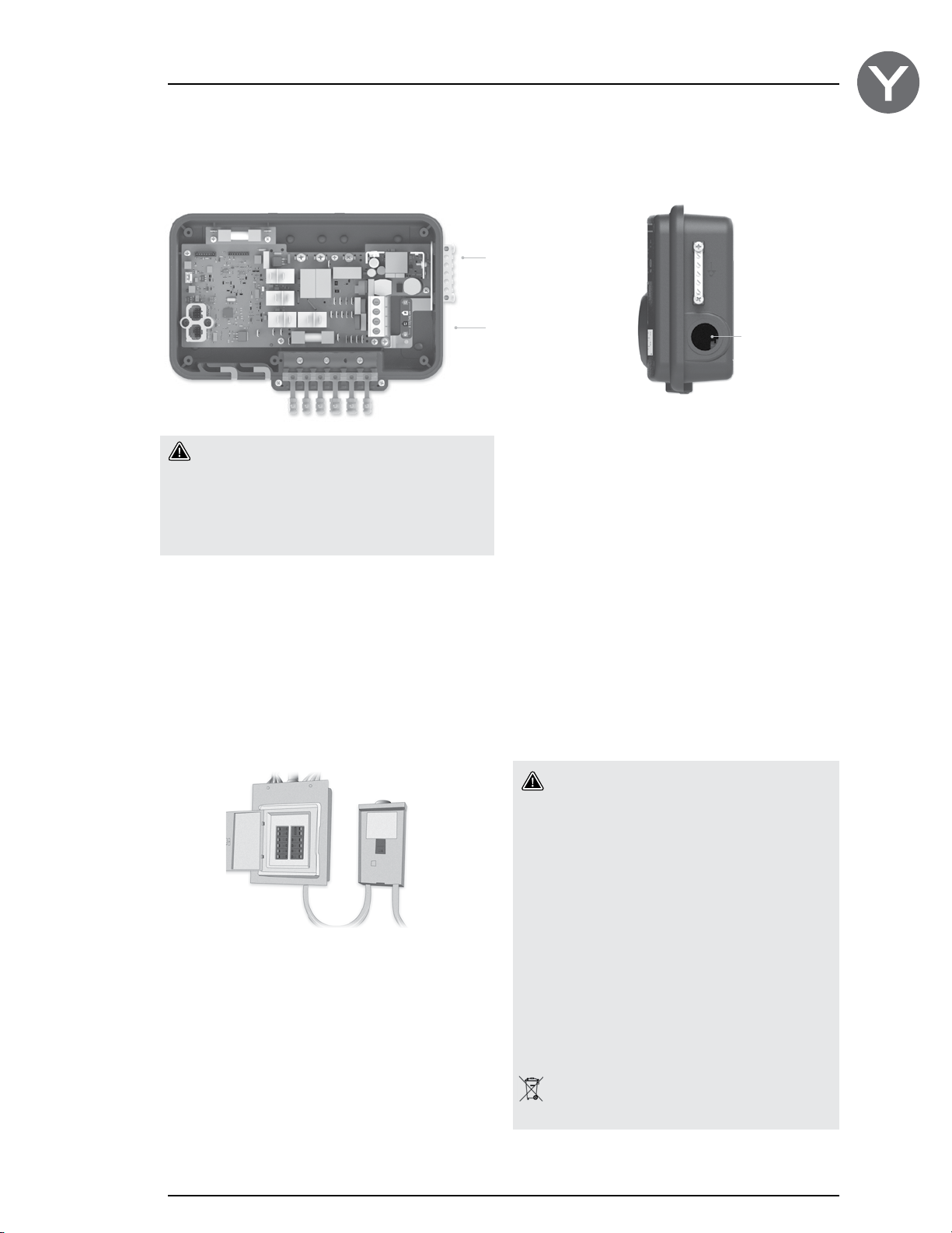
Electrical wiring: all models
Bonding lugs
Warning!
Disconnect power before starting electrical work.
Wiring must be completed by a qualified electrician
and must be done in accordance with the local
electrical code.
Main power entry
Main power entry
To complete the electrical connections of the in.yj control
system you will need a Phillips screwdriver and a flat-head
screwdriver.
Remove the screws from the system control lid and
remove it.
Remove 5 1/2" (142 mm) of cable insulation.
Strip away 1/2" (15 mm) of insulation from each wire.
Pull the cable through the cutout of the box and secure
it with a 3/4" NPT strain relief* (hole diameter 1.09"
{27.6 mm}). Ensure that the NPT strain relief clamps
around the outer sheath of the cable.
*For CE/AUS/NZ use an IEC certified plastic bushing that will
maintain the IPX5 rating.
Main electrical box GFCI panel
Warning!
For units for use in other than single-family
dwellings, a clearly labeled emergency switch
shall be provided as part of the installation.
The switch shall be readily accessible to the
occupants and shall be installed at least 5' (1.52 m)
away, adjacent to, and within sight of the unit.
----This product must always be connected to a
circuit protected by a ground fault interrupter.
----Proper wiring of the electrical service box,
GFCI and in.yj terminal block is essential!
----Check your electrical code for local regulations.
Only copper wire should be used, never aluminum.
-----
Disposal of the product
The appliance (or the product) must be disposed
of separately in accordance with the local waste
disposal legislation in force.
15
Page 18
Electrical wiring
Electrical wiring: North Amercian model
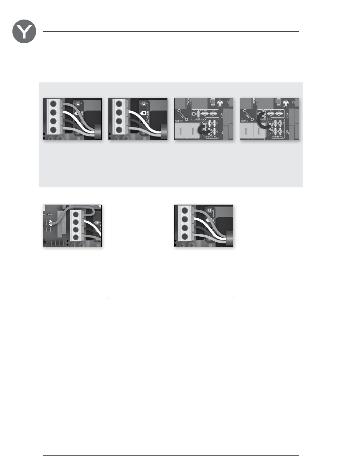
Refer to wiring diagram in the enclosure box lid for more information.
Before November 2014
240 V (4 wires) 120 V (3 wires) 240 V (4 wires) Default
Insert each wire into the appropriate socket of the main
entry terminal block according to the color code indicated
on the sticker. Use a flat screwdriver to tighten the screws
on the terminal.
The heater is factory configured at 240 V (4 kW).
To convert it to 120 V (1 kW) configuration, move the wire
jumper from P35-P20 (240 V) to P35 - P14 (120 V)
120 V (3 wires)
After November 2014
120 V (3 wires) 240 V (4 wires)
DO NOT REMOVE THE BROWN WIRE. Insert each wire
into the appropriate socket of the main entry terminal block
according to the color code indicated on the sticker. Use a
flat screwdriver to tighten the screws on the terminal.
After making sure wires are securley connected, push them back into the box and replace the cover. Do not over tighten
cover screws (torque to 8 in.lb max {0.9 N.m.}). Connect the bonding conductor to the bonding lug on the side of the spa
pack (a grounded electrode conductor should be used to connect the equipment grounding conductors).
Remove the brown wire and insert each wire into the
appropriate socket of the main entry terminal block according to the color code indicated on the sticker. Use a flat
screwdriver to tighten the screws on the terminal.
16
Page 19
Electrical wiring
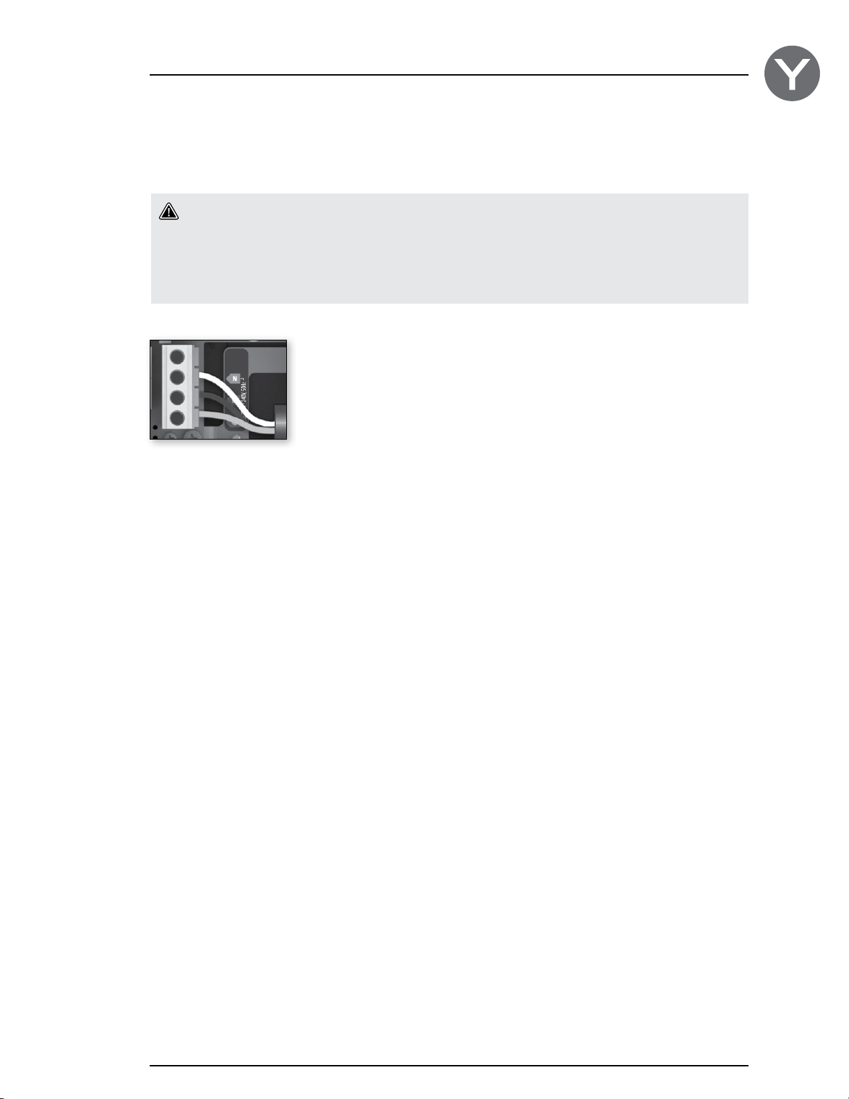
Electrical wiring: CE/AUS/NZS models
Refer to wiring diagram in the enclosure box lid for more information.
Warning!
in.yj.ce models must always be connected to a circuit protected by a Residual-Current Device (RCD)
having a rated operating residual-current not exceeding 30 mA.
Correct wiring of the electrical service box, RCD, and pack terminal block is essential!
Check your electrical code for local regulations. Only copper wire should be used, never aluminum.
230 V (3 wires)
Insert each wire into the appropriate socket of the main entry terminal block according to the color code indicated on the
sticker. Use a flat screwdriver to tighten the screws on the terminal.
After making sure wires are securley connected, push them back into the box and replace the cover. Do not over tighten
cover screws (torque to 8 in.lb max {0.9 N.m.}).
Connect the bonding conductor to the bonding lug on the side of the spa pack (a grounded electrode conductor should be
used to connect the equipment grounding conductors).
17
Page 20

Controler power up
Start up of your control system
To perform the control system start up, refer to the manual:
Start up guide and basic configuration
18
Page 21
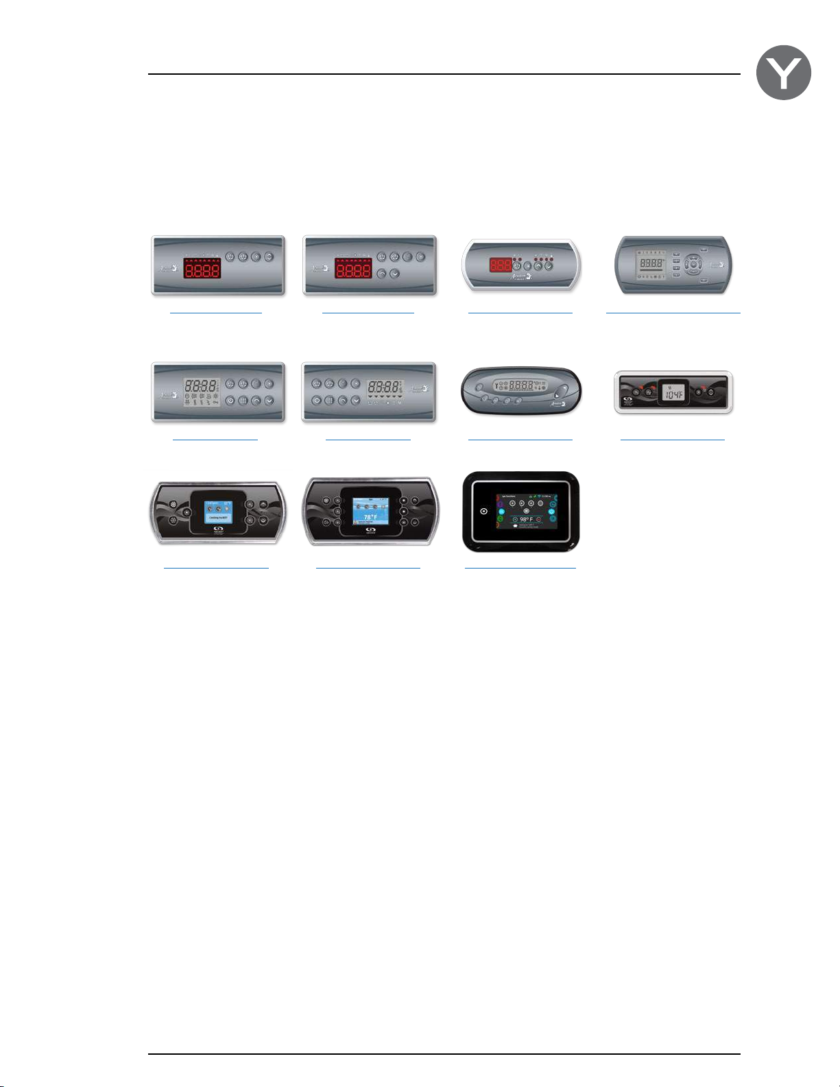
Compatible keypads
List of compatible keypads for the in.yj control system
For more information on the compatible keypads for your control system refer to the corresponding Techbook.
K-19 main keypad
LED display, 4 keys
K-4 main keypad
LCD display, 8 keys
in.k500 main keypad
Color LCD display, 7 keys
K-35 main keypad
LED display, 6 keys
K-8 main keypad
LCD display, 8 keys
in.k800 main keypad
Color LCD display, 10 keys
in.k200 main keypad
LED display, 4 keys
in.k450 main keypad
LCD display, 7 keys
in.k1000 main keypad
Color LCD capacitive
touchscreen display
in.k600 static main keypad
LCD display, 11 keys
in.k300 main keypad
LCD display, 4 keys
19
Page 22
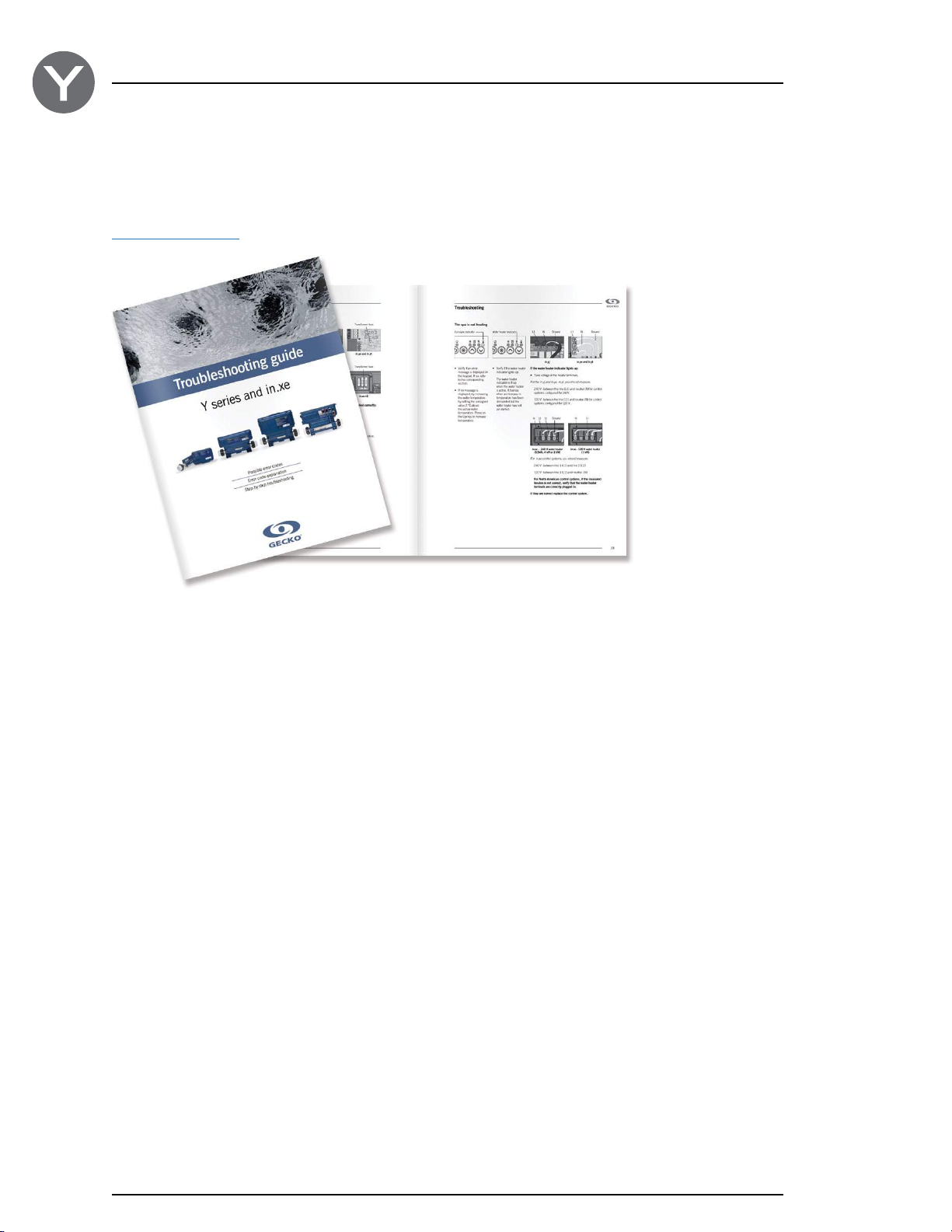
Troubleshooting
Troubleshooting information for your control system
You come across a problem with your control system, for the troubleshooting of your control system, refer to the manual:
Troubleshooting guide
20
Page 23
Specifications
Model
in.yj-2: 2 outputs
in.yj-3: 3 outputs
Environmental ratings
Operating temperature: 32˚F (0°C) to 140˚F (60˚C)
Storage temperature: -13°F (-25°C) to 185°F (85°C)
Humidity: Up to 85% RH, non condensing
Level of waterproofing: IPx5 for TUV (CE/AUS/NZS) & CSA Enclosure #2
Mechanical
in.yj
Weight: 3.1 lb (1.41 kg)
Dimensions (W x H x D): 12.08" x 7.38" x 3.74" (307 x 187 x 95 mm)
heat.wav
Weight: 4.65 lb (2.1 kg)
Dimensions (W x H x D): 19.58" x 4.94" x 3.92" (497 x 125 x 100 mm)
in.yj UL/CSA electrical specifications*
1
Input rating (in.yj-3) : 120/240 V nominal (+5/-10 %)
60 Hz, (2 lines required with neutral) 40 A max.
Input rating (in.yj-2) : 120/240 V nominal (+5/-10 %)
60 Hz, (2 lines required with neutral) 32 A max.
or : 120 V nominal only (+5/-10%) , (single line with neutral) 16 A Max
Heat.wav rating :
Voltage : 120 V or 240 V, 1 kW at 120 V
Wattage : 4 kW at 240 V, 1 kW at 120 V
Flow rate : Minimum of 18 GPM (68,1 LPM) is required
2
Device*
Voltage*3 Maximum current
Pump 1 (2-spd) 120 or 240 V 15 FLA/60 LRA (inrush)
Pump 2 (1-spd)*
5
O3*
120 or 240 V 3 FLA/6 A
4
120 or 240V 15 FLA/60 LRA (inrush)
Direct out 1 120 or 240 V 5 A (always on)
Light output 12 Vdc 0,5 AMP (6W Light bulb)
UL/CSA Standards
UL 1563 Sixth Ed. (2012)
UL File: E182156
CSA No. 22.2 - 218.1-M89. (2013)
1
*
Certain current limits may apply. Please talk to your customer service representative for more information.
2
*
Total of Pump 1, O3 and Direct out should not exceed 16 A for UL/CSA version.
3
*
The output voltage is selectable only if input supply voltage is 120/240 V.
4
*
Only available on in.yj-3.
5
*
The ozonator is connected in parallel with the Pump 1 low speed, therefore they cannot be controlled independently.
21
Page 24
Specifications
in.yj TUV (CE/AUS/NZA) electrical specifications*
1
Input rating (in.yj-3) : 220 - 240 V nominal with neutral (+5/-10%)
50/60 Hz
Monophase system 40 A max.
Input rating (in.yj-2) : 220 - 240 V nominal with neutral (+5/-10 %)
50/60 Hz
Monophase system 32 A max.
Heat.wav rating :
Voltage : 220/240 V, 50/60 Hz
Wattage : 4 kW at 220 - 240 V
Flow rate : Minimum of 18 GPM (68,1 LPM) is required
2
Device*
Voltage*3 Maximum current
Pump 1 (2-spd) 220/240 V 15 FLA/60 LRA (inrush)
Pump 2 (1-spd)*
5
O3*
220/240 V 3 FLA/6 A
4
220/240 V 15 FLA/60 LRA (inrush)
Direct out 1 220/240 V 5 A (always on)
Light output 12 Vdc 0,5 AMP (6W Light bulb)
TUV Standards
EN/IEC 60335 - 2 - 60: /A12:2010 - EN/IEC 60335 - 1: /A15:2011
EN55014-1
EN55014-2
EN61000-3-2
EN61000-3-3
22
1
*
Certain current limits may apply. Please talk to your customer service representative for more information.
2
*
Total of Pump 1, O3, heater, and Direct out should not exceed 32 A for TUV (CE/AUS/NZA) version.
3
*
The output voltage for the TUV (CE/AUS/NZA) version will reflect the input voltage, typically 230 V.
4
*
Only available on in.yj-3
5
*
The ozonator is connected in parallel with the Pump 1 low speed, therefore they cannot be controlled independently.
Page 25

Page 26
9919-101235-C
Rev. 11-2015
© Groupe Gecko Alliance inc., 2015
All trademarks or registered trademarks
are the property of their respective owners.
450 des Canetons, Quebec City (Qc), G2E 5W6 Canada, 1.800.78.GECKO
Gecko Alliance
www.geckoalliance.com
Printed in Canada
 Loading...