

Page 1
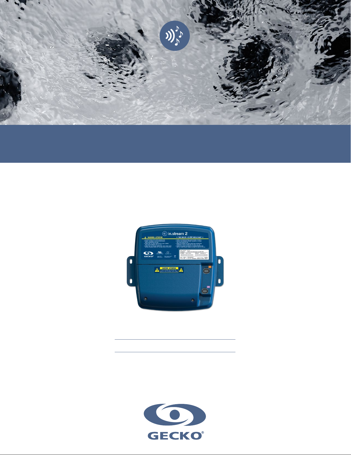
TechBook
in.stream 2
audio station for spas
Awesome sound quality
All in one audio system and power supply
Full control of your audio from spa side
Page 2

Table of contents
Safety instructions ............................................................................................................................................................ 2
Warnings ......................................................................................................................................................................... 3
Introduction ..................................................................................................................................................................... 5
Overview .......................................................................................................................................................................... 6
Dimensions ...................................................................................................................................................................... 7
Installation ....................................................................................................................................................................... 8
- in.stream 2 positioning ....................................................................................................................................... 8
- in.stream 2 installation procedure with standard wall mounting bracket ............................................................ 9
- in.stream 2 installation procedure with wall mounting Z-bracket ........................................................................ 9
Connections
- Preparation ....................................................................................................................................................... 10
- Connecting the speakers and subwoofer .......................................................................................................... 10
- Speaker cables ................................................................................................................................................. 11
- Optional adapter cables .................................................................................................................................... 11
- Connecting the docking station in.p4 to the in.stream 2 ................................................................................... 12
- Completing the cabling ..................................................................................................................................... 13
Bluetooth overview
- Pairing with a Bluetooth enabled device ........................................................................................................... 14
Firmware update ........................................................................................................................................................... 15
Compatible keypads ...................................................................................................................................................... 16
Regulatory statement ..................................................................................................................................................... 17
Specifications ................................................................................................................................................................ 18
1
Page 3
Safety instructions
CAUTION
RISK OF ELECTRIC SHOCK
DO NOT OPEN
CAUTION: TO REDUCE THE RISK OF ELECTRIC SHOCK, DO NOT REMOVE SCREWS ON THE BACK OF
THE ENCLOSURE. NO USER-SERVICEABLE PARTS INSIDE. REFER SERVICING TO QUALIFIED SERVICE
PERSONNEL.
The lightning flash with the arrowhead symbol within an equilateral triangle is intended to alert the user to
the presence of uninsulated ‘‘dangerous voltage’’ within the product’s enclosure that may be of sufficient
magnitude to constitute a risk of electric shock to persons.
The exclamation point within an equilateral triangle is intended to alert the user to the presence of important
operating and maintenance (servicing) instructions in the service literature accompanying this appliance.
IMPORTANT SAFETY INSTRUCTIONS:
For your own safety please read the following important safety instructions carefully before attempting to
connect this unit to the mains power supply. They will also enable you to get the best performance from and
prolong the life of the unit:
* READ THESE INSTRUCTIONS.
* KEEP THESE INSTRUCTIONS.
* HEED ALL WARNINGS.
* FOLLOW ALL INSTRUCTIONS.
* CLEAN ONLY WITH DRY CLOTH. BEWARE THE APPLICATION OF SOME PRODUCTS COMMONLY USED AGAINST
CORROSION (SUCH AS WD-40 FAMILY PRODUCTS) AS THEY COULD DAMAGE THE ENCLOSURE, DUE TO A NEGATIVE
CHEMICAL REACTION BETWEEN SOME INDUSTRIAL OILS AND ITS PLASTIC ENCLOSURE. ANY OTHER MATERIALS WHICH
MAY COME IN CONTACT WITH THE ENCLOSURE MUST BE CAREFULLY EVALUATED UNDER END USE CONDITIONS FOR
COMPATIBILITY.
* DO NOT BLOCK ANY VENTILATION OPENINGS. INSTALL IN ACCORDANCE WITH THE MANUFACTURER'S INSTRUCTIONS.
* DO NOT INSTALL NEAR ANY HEAT SOURCES. CLEARANCE AND MINIMUM DISTANCE BETWEEN THE VARIOUS PARTS OF
THE APPLIANCE AND THE SURROUNDING STRUCTURE ARE NOT SPECIFIED AS LONG AS THEY ARE SUFFICIENT SO THAT
THE AMBIENT TEMPERATURE AROUND THE APPARATUS DOES NOT EXCEED 140°F (60°C).
* DO NOT DEFEAT THE SAFETY PURPOSE OF THE POLARIZED OR GROUNDING-TYPE PLUG. A POLARIZED PLUG HAS TWO
BLADES WITH ONE WIDER THAN THE OTHER. A GROUNDING TYPE PLUG HAS TWO BLADES AND A THIRD GROUNDING
PRONG. THE WIDE BLADE OR THE THIRD PRONG ARE PROVIDED FOR YOUR SAFETY. IF THE PROVIDED PLUG DOES NOT
FIT INTO YOUR OUTLET, CONSULT AN ELECTRICIAN FOR REPLACEMENT OF THE OBSOLETE OUTLET.
* PROTECT THE POWER CORD FROM BEING WALKED ON OR PINCHED PARTICULARLY AT PLUGS, CONVENIENCE
RECEPTACLES, AND THE POINT WHERE THEY EXIT FROM THE APPARATUS.
* ONLY USE ATTACHMENTS/ACCESSORIES SPECIFIED BY THE MANUFACTURER.
* UNPLUG THIS APPARATUS DURING LIGHTNING STORMS OR WHEN UNUSED FOR LONG PERIODS OF TIME.
* REFER ALL SERVICING TO QUALIFIED SERVICE PERSONNEL. SERVICING IS REQUIRED WHEN THE APPARATUS HAS
BEEN DAMAGED IN ANY WAY, SUCH AS POWER-SUPPLY CORD OR PLUG IS DAMAGED, LIQUID HAS BEEN SPILLED OR
OBJECTS HAVE FALLEN INTO THE APPARATUS, THE APPARATUS HAS BEEN EXPOSED TO RAIN OR MOISTURE, DOES NOT
OPERATE NORMALLY, OR HAS BEEN DROPPED.
Aeware®, Gecko®, and their respective logos are Registered Trademarks of Gecko Alliance Group.
in.stream 2™, in.k1000™, in.k800™, in.k500™ and their respective logos are Trademarks of Gecko Alliance Group.
All other product or company names that may be mentioned in this publication are tradenames, trademarks or registered trademarks
of their respective owners.
2
Page 4
Warnings
WARNINGS:
Before installing or connecting the unit, please read the following.
* DO NOT DISASSEMBLE OR ALTER THE APPARATUS.
* DO NOT USE FOAM TO ISOLATE THE UNIT.
* TURN POWER OFF BEFORE SERVICING OR MODIFYING ANY CABLE CONNECTIONS IN THIS UNIT.
* TO PREVENT ELECTRIC SHOCK HAZARD AND/OR WATER DAMAGE TO THIS APPARATUS, ALL CONDUITS MUST BE
PLUGGED WITH THE ATTACHED GASKET.
* AUDIO/VIDEO COMPONENTS SHALL BE LOCATED ABOVE THE FLOOD ZONE WHERE THEY ARE UNLIKELY TO BE
SUBMERGED IN THE EVENT THE SPA IS OVERFILLED (OR SIMILAR ABNORMAL CONDITION OCCURENCE).
* PRODUCT MUST BE DISPOSED OF SEPARATELY IN ACCORDANCE WITH LOCAL WASTE DISPOSAL LEGISLATION.
WARNINGS:
When this equipment is provided as an audio/video components for spas, U1563 - 6th edition requires
that the following instructions (or equivalent) be provided as part of the instruction manual for the spa
equipment.
* "CAUTION – RISK OF ELECTRIC SHOCK. DO NOT LEAVE COMPARTMENT DOOR OPEN";
* "CAUTION – RISK OF ELECTRIC SHOCK. REPLACE COMPONENTS ONLY WITH IDENTICAL COMPONENTS";
* "DO NOT OPERATE THE AUDIO/VIDEO CONTROLS WHILE INSIDE IN THE SPA".
* "WARNING – PREVENT ELECTROCUTION. DO NOT CONNECT ANY AUXILIARY COMPONENTS (FOR EXAMPLE
CABLE, ADDITIONAL SPEAKERS, HEADPHONES, ADDITIONAL AUDIO/VIDEO COMPONENTS, ETC.) TO THE
SYSTEM".
* THESE UNITS ARE NOT PROVIDED WITH AN OUTDOOR ANTENNAE; WHEN PROVIDED, IT SHOULD BE INSTALLED
IN ACCORDANCE WITH ARTICLE 810 OF THE NATIONAL ELECTRICAL CODE, ANSI/NFPA 70.
* DO NOT SERVICE THIS PRODUCT YOURSELF AS OPENING OR REMOVING COVERS MAY EXPOSE YOU TO
DANGEROUS VOLTAGE OR OTHER RISK OF INJURY. REFER ALL SERVICING TO QUALIFIED SERVICE PERSONNEL.
* WHEN THE POWER SUPPLY CONNECTIONS OR POWER SUPPLY CORD(S) ARE DAMAGED; IF WATER IS ENTERING THE
AUDIO/VIDEO COMPARTMENT OR ANY ELECTRICAL EQUIPMENT COMPARTMENT AREA; IF THE PROTECTIVE SHIELDS OR
BARRIERS ARE SHOWING SIGNS OF DETERIORATION; OR IF THERE ARE SIGNS OF OTHER POTENTIAL DAMAGE TO THE
UNIT, TURN OFF THE UNIT AND REFER SERVICING TO A QUALIFIED SERVICE PERSONNEL.
* THIS UNIT SHOULD BE SUBJECTED TO PERIODIC ROUTINE MAINTENANCE (FOR EXAMPLE, ONCE EVERY 3 MONTHS) TO
MAKE SURE THAT THE UNIT IS OPERATING PROPERLY.
* PRODUCT MUST BE DISPOSED OF SEPARATELY IN ACCORDANCE WITH LOCAL WASTE DISPOSAL LEGISLATION.
3
Page 5

4
Page 6
Introduction
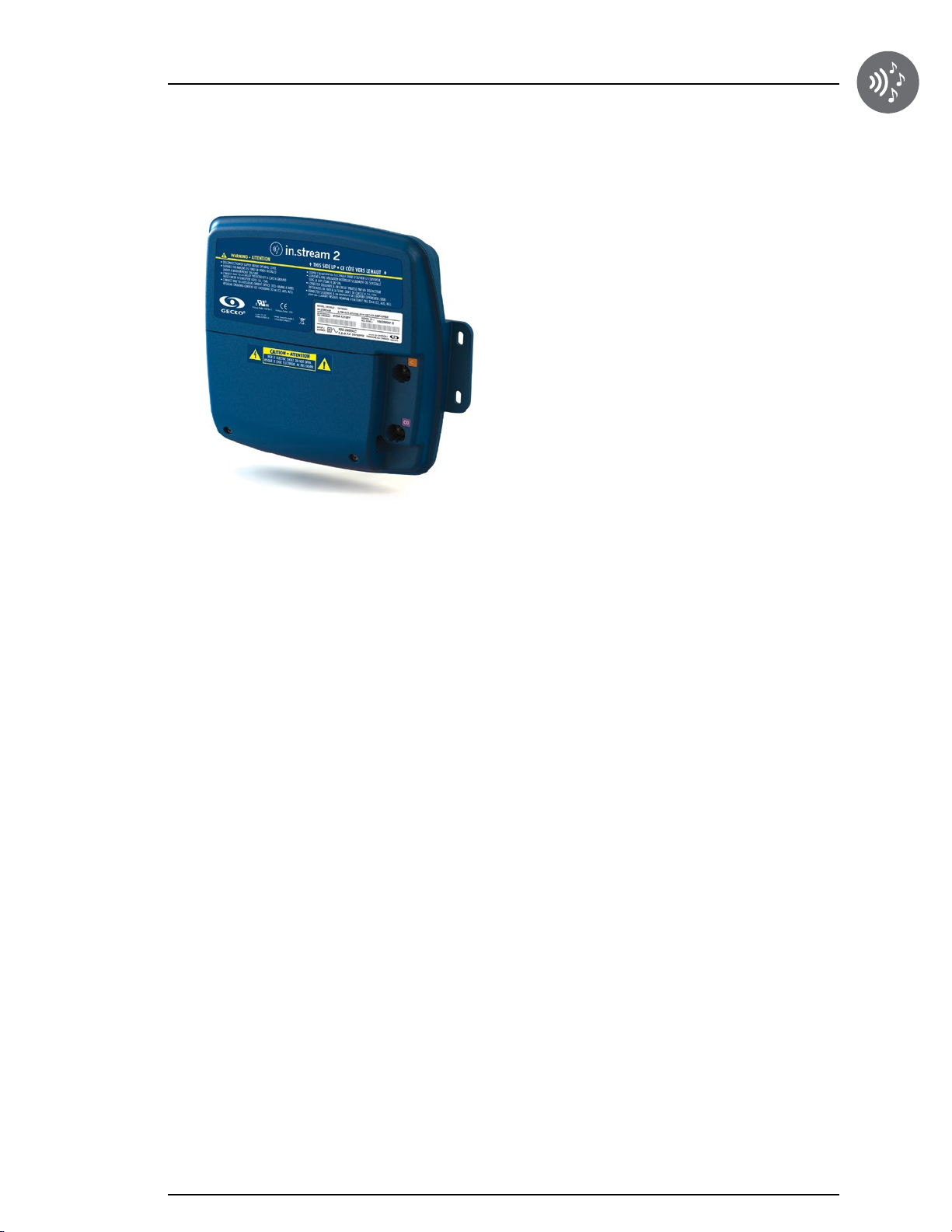
in.stream 2
audio station for spas
In.stream 2 audio system offers you the perfect means
to bring music into your spa. The in.stream 2 is simple
to install and compatible with numerous audio sources.
For example, you may connect the in.stream 2 to an iPod
using the auxiliary audio input or play music wirelessly
using a Bluetooth mobile device. Listen to music in MP3
format saved on a USB flash disk or tune in to an FM
station of your choice using the in.stream 2 integrated
FM receiver. Depending on the configuration used,
the in.stream 2 can handle up to 4 speakers and one
subwoofer.
The audio station can be used to charge most mobile
devices on the market with its onboard USB charger
controller.
Powered with its own internal universal power supply,
the in.stream 2 can be used in any place in the world.
All the electronics circuits are contained in a innovatively
designed and splashproof plastic enclosure.
The in.stream 2 is equipped with state of the art class D
audio amplifiers. This type of amplifier is very power
efficient and dissipates much less heat than any
comparable audio system for use in spa.
Depending on the selected configuration, the in.stream 2
conveniently lets you control music from the main keypad
or may be used as a stand-alone.
Main characteristics
• Fully splashproof (IPx5)
• Integrated universal power supply
• 1 auxiliary input
• Compatible USB port
• Integrated FM receiver with external antenna
• Bluetooth receiver
• Mobile device USB charger controller
• Up to 4 speakers and one subwoofer
5
Page 7
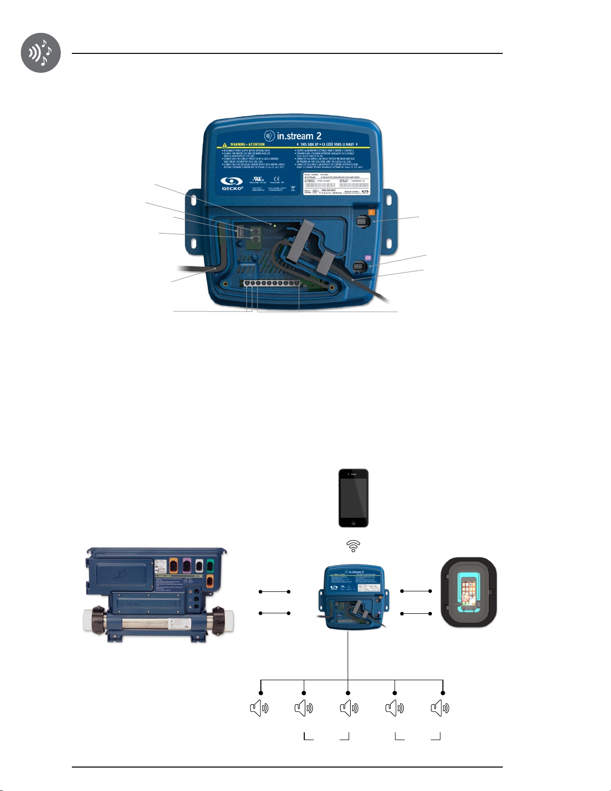
Overview
Status LED
Auxiliary
USB connector
FM antenna
AC power input
in.link keypad
To CO Acc
To CO Pack
Subwoofer ouput
Speakers outputs
Depending on the chosen configuration, the in.stream 2 can support up to 4 speakers, 1 subwoofer, an auxiliary input, a
USB connection with 1A charging capability, FM radio receiver and Bluetooth streaming.
The in.p4 waterproof enclosure, which provides protection to your iPod or smart phone, is available as an option.
With a compatible keypad, you will have full control over the in.stream 2 features from inside of your spa.
Bluetooth
AC input
USB
Communication link
AUX input
in.p4
Subwoofer
Right
Rear
Left
Right
Left
Front
6
Page 8
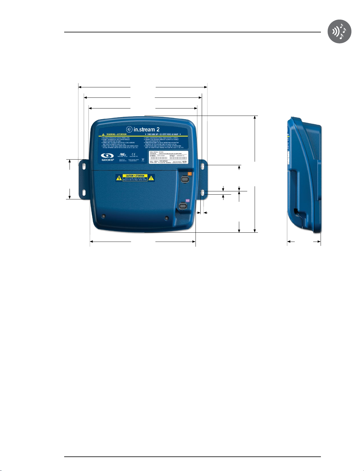
Dimensions
3,06"
(78 mm)
9,81"
(249 mm)
9"
(228 mm)
8,28"
(210 mm)
0,22"
(5 mm)
0,25"
(6 mm)
2,00"
(51 mm)
3,17"
(81 mm)
8,88"
(226 mm)
8,06"
(205 mm)
2,58"
(65 mm)
Front view Side view
7
Page 9
Installation
in.stream 2 positioning
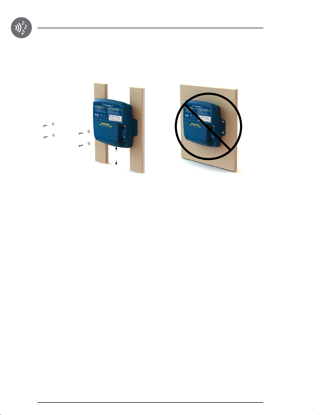
To prevent water from getting inside the device, the in.stream 2 should be installed on a vertical surface as shown below:
4"
(100 mm)
Note: The in.stream 2 must be installed at least 4" (100mm) above potential flood level. A clearance of at least 0.75" (19 mm) is
required to have a free heat circulation at the back of the unit.
Secure the in.stream 2 onto two wall studs.
Firmly attach upper mounting holes one at a time on each
side of the apparatus.
Repeat the process for lower mounting holes.
The following materials are recommended:
4 # 10 screws of appropriate length with round,
truss or pan head.
4 washers 0.5" OD x .0625” thickness
(12 mm OD x 1.5 mm)
Note:
• Do not use foil insulation in front of the unit.
• Place the unit far from any radio noise source such as variable speed control and motor.
• If present, install the FM antenna in a vertical orientation and fully deployed.
• This unit is equipped with an automatic audio volume control that is active when temperature inside the enclosure is very high.
8
Page 10
Installation
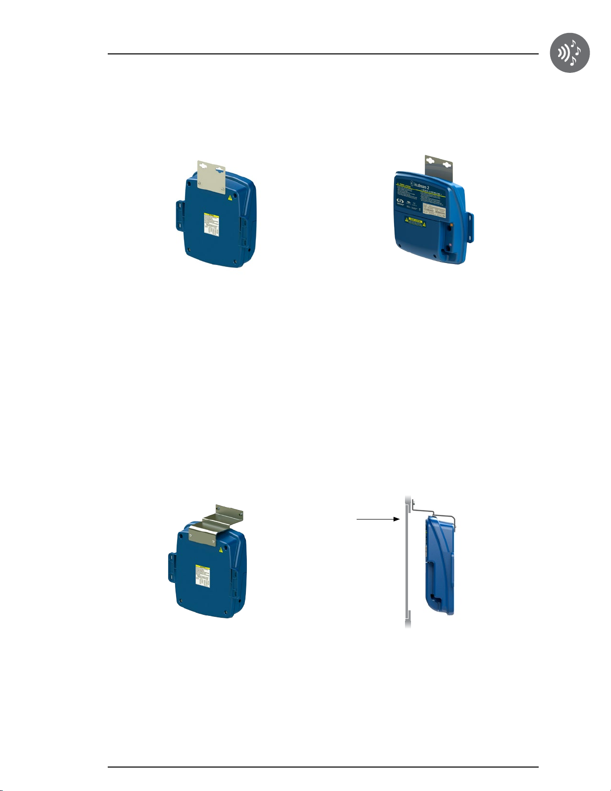
You may also mount your audio station using two different types of brackets (optional):
in.stream 2 installation procedure with standard wall mounting bracket
Flat aluminum bracket are designed for back wall
mounting.
Using the bracket, fasten unit to 2" x 4" or 2" x 6" timber
wall studs under the spa. We recommend using #10 self
threading screws with pan or truss heads and washers
Fasten the mounting bracket to the back of the in.stream 2
1/2" OD x 1/16” (12 mm OD x 1.5 mm).
with the supplied screws.
Part number:
Wall mount bracket kit 100 pcs - 9920-101474
(with 200 screws to attach to unit)
Note: The in.stream 2 must be installed at least 4" (100 mm)
above potential flood level. If floor is on ground level, pack should
be raised at least 4" (100 mm).
in.stream 2 installation procedure with wall mounting Z-bracket
Access door
The aluminum Z-bracket is designed for flush-mounting
the unit directly on the edge of the access door frame
of your spa.
Fasten the mounting bracket to the back of the in.stream 2
with the supplied screws.
Part number:
Z-bracket kit 100 pcs - 9920-101478
(Comes with 200 screws to attach to unit.)
Depending on your specific needs, you can fasten with
two #10-24 screws of your choice.
Note: The in.stream 2 must be installed at least 4" (100 mm)
above potential flood level. If the floor is on ground level, the pack
should be raised by at least 4" (100 mm).
9
Page 11
Connections
Preparation
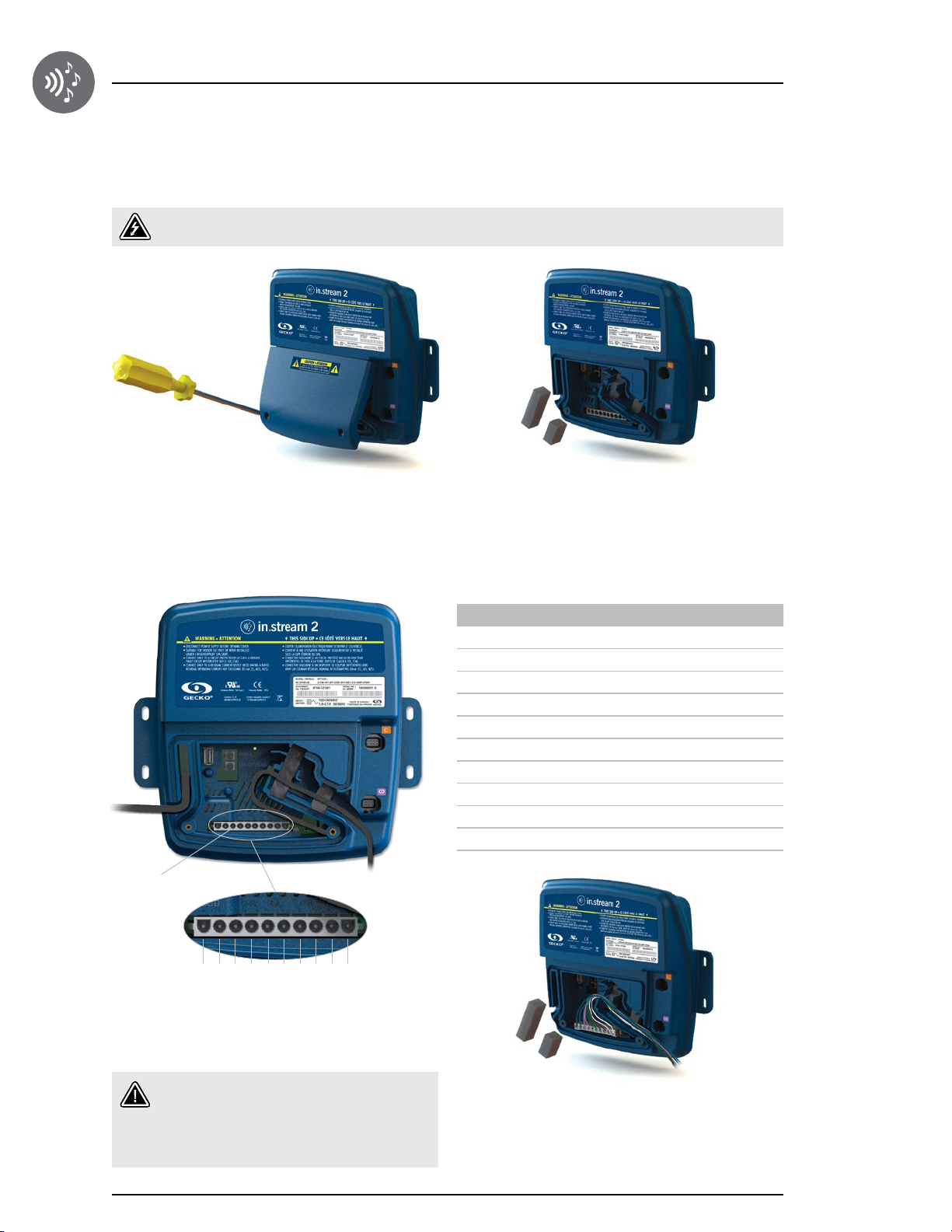
To prevent electric shock hazard, do not connect to main power supply while the cover is removed.
Remove the cover screws from the front of the apparatus
with a Phillips screw driver.
Connecting the speakers and subwoofer
Class 2 Wiring
Remove cover and put aside the foam gaskets located in
the wire channel.
Connector pins Identification
1 Front Left speaker (+)
2 Front Left speaker (-)
3 Front Right speaker (-)
4 Front Right speaker (+)
5 Rear Left speaker (+)
6 Rear Left speaker (-)
7 Rear Right speaker (-)
8 Rear Right speaker (+)
9 Subwoofer (+)
10 Subwoofer (-)
10
138 510 27 49 6
The speakers and the subwoofer output terminals are
located on the 10-pin MATE-N-LOK connector marked
"SUB R-R R-L F-R F-L"
Caution: The in.stream 2 does not come with
speakers and associated wiring. The interconnection between the audio system and the
speakers must be "Class 2 Wiring" and be done
by qualified personnel.
To connect your own speaker cable or to connect the
optional adaptor, insert the 10-pin connector into the
appropriate connector. Route the wires through the
molded strain relief channel as illustrated.
Page 12
Connections
Speaker cables
Customer made cable
For customer that want to build their own cable, the following parts can be used.
The required housing connector is a 10 position Universal MATE-N-LOK.
TE CONNECTIVITY: Part number 926302-3
The suggested crimping contact are for AWG 14-20 TE CONNECTIVITY:
Part number 350550-3
Optional adapter cables
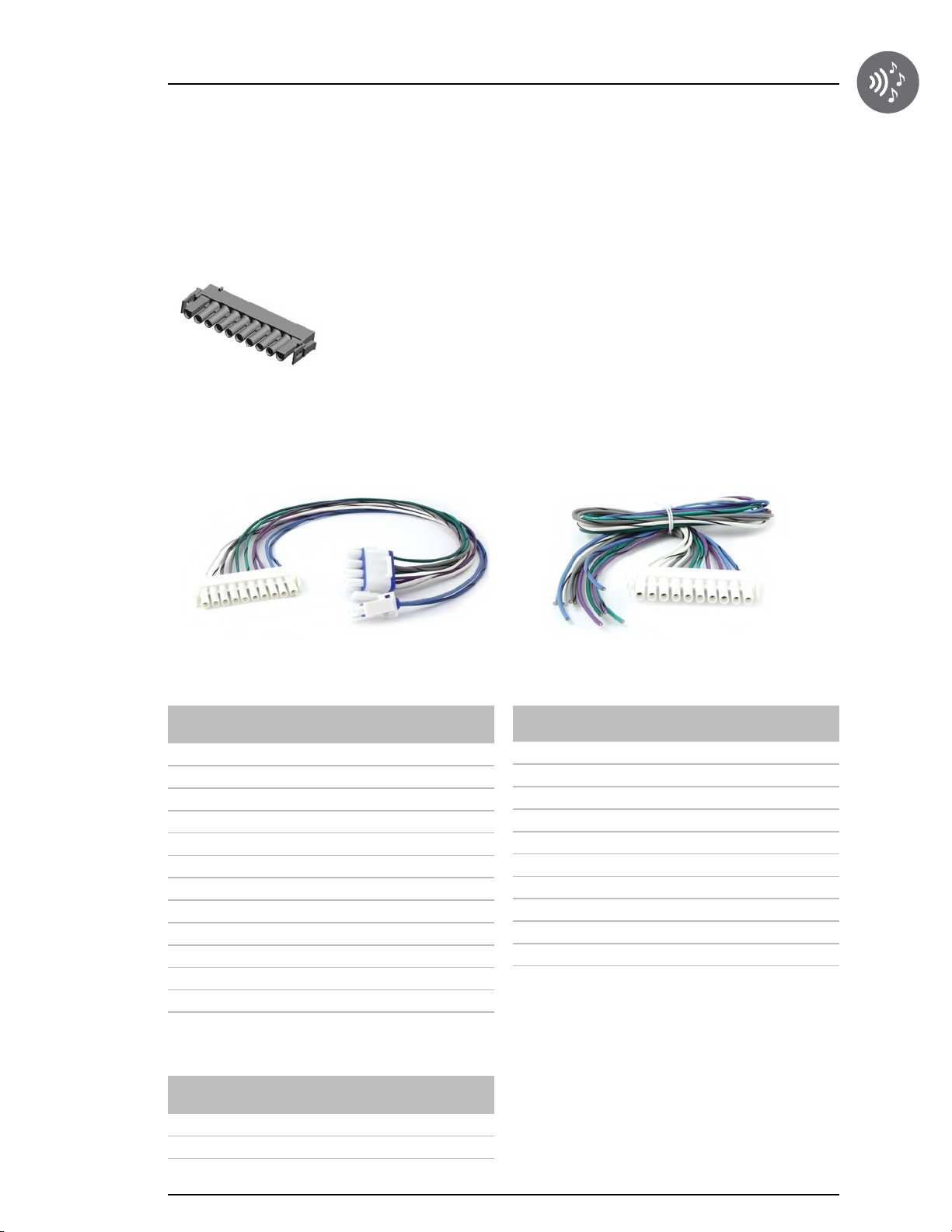
An optional adapter cable allows you to connect the 10-pin connector from the in.stream 2 to the 3x4-pin connector
commonly used in spa audio systems. With this adaptor, the subwoofer output is on a separate 1x2-pin connector.
Part number: 9920-401425 Part number: 9920-401428
3x4-pin
Connector
pins
1 NC NC
2 NC NC
3 Rear Left speaker (+) Green
4 Rear Left speaker (-) Green-Black
5 Front Right speaker (+) Gray
6 Front Right speaker (-) Gray-Black
7 Rear Right speaker (+) Purple
8 Rear Right speaker (-) Purple-Black
9 NC NC
10 Front Left speaker (+) White
11 Front Left speaker (-) White-Black
12 NC NC
Identification Wire Color
1x2-pin
Connector
pins
1 Subwoofer (+) Blue
2 Subwoofer (-) Blue-Black
Identification Wire Color
10-pin
Connector
pins
1 Front Left speaker (+) White
2 Front Left speaker (-) White-Black
3 Front Right speaker (-) Gray-Black
4 Front Right speaker (+) Gray
5 Rear Left speaker (+) Green
6 Rear Left speaker (-) Green-Black
7 Rear Right speaker (-) Purple-Black
8 Rear Right speaker (+) Purple
9 Subwoofer (+) Blue
10 Subwoofer (-) Blue-Black
Identification
Wire Color
11
Page 13
Connections
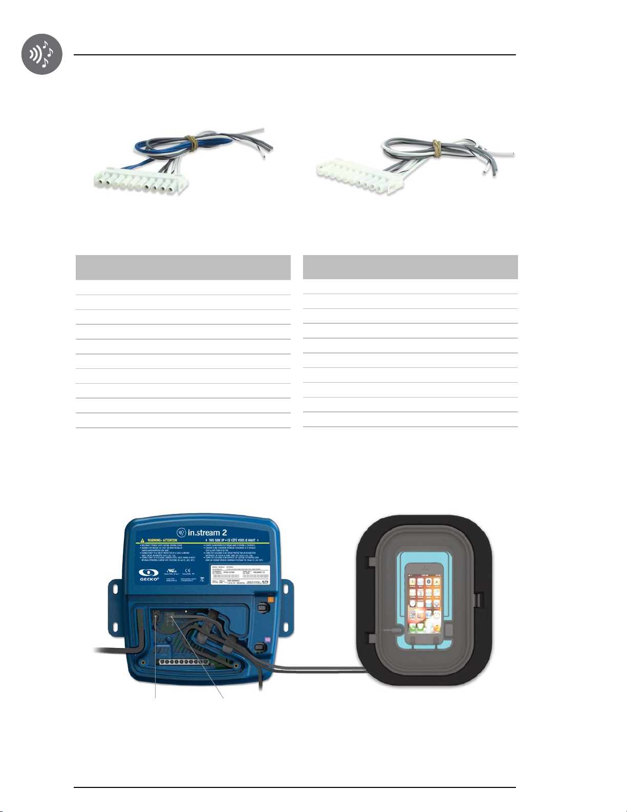
Part number: 9920-401433 Part number: 9920-401434
10-pin 10-pin
Connector
pins
1 Front Left speaker (+) White
2 Front Left speaker (-) White-Black
3 Front Right speaker (-) Gray-Black
4 Front Right speaker (+) Gray
5 NC NC
6 NC NC
7 NC NC
8 NC NC
9 Subwoofer (+) Blue
10 Subwoofer (-) Blue-Black
Identification Wire Color
Connector
pins
1 Front Left speaker (+) White
2 Front Left speaker (-) White-Black
3 Front Right speaker (-) Gray-Black
4 Front Right speaker (+) Gray
5 NC NC
6 NC NC
7 NC NC
8 NC NC
9 NC NC
10 NC NC
Identification
Connecting the docking station in.p4 to the in.stream 2
The in.p4 docking station features a USB and an 1/8" (3,5 mm) audio input mini jack connector.
Wire Color
12
USB connector Auxiliary
To connect the docking station into the in.stream 2, simply insert the USB cable into the USB receptacle and the 1/8"
(3,5 mm) mini jack into the AUX receptacle as illustrated.
Route both cables through the molded strain relief channel as illustrated.
Page 14
Connections
Completing the cabling
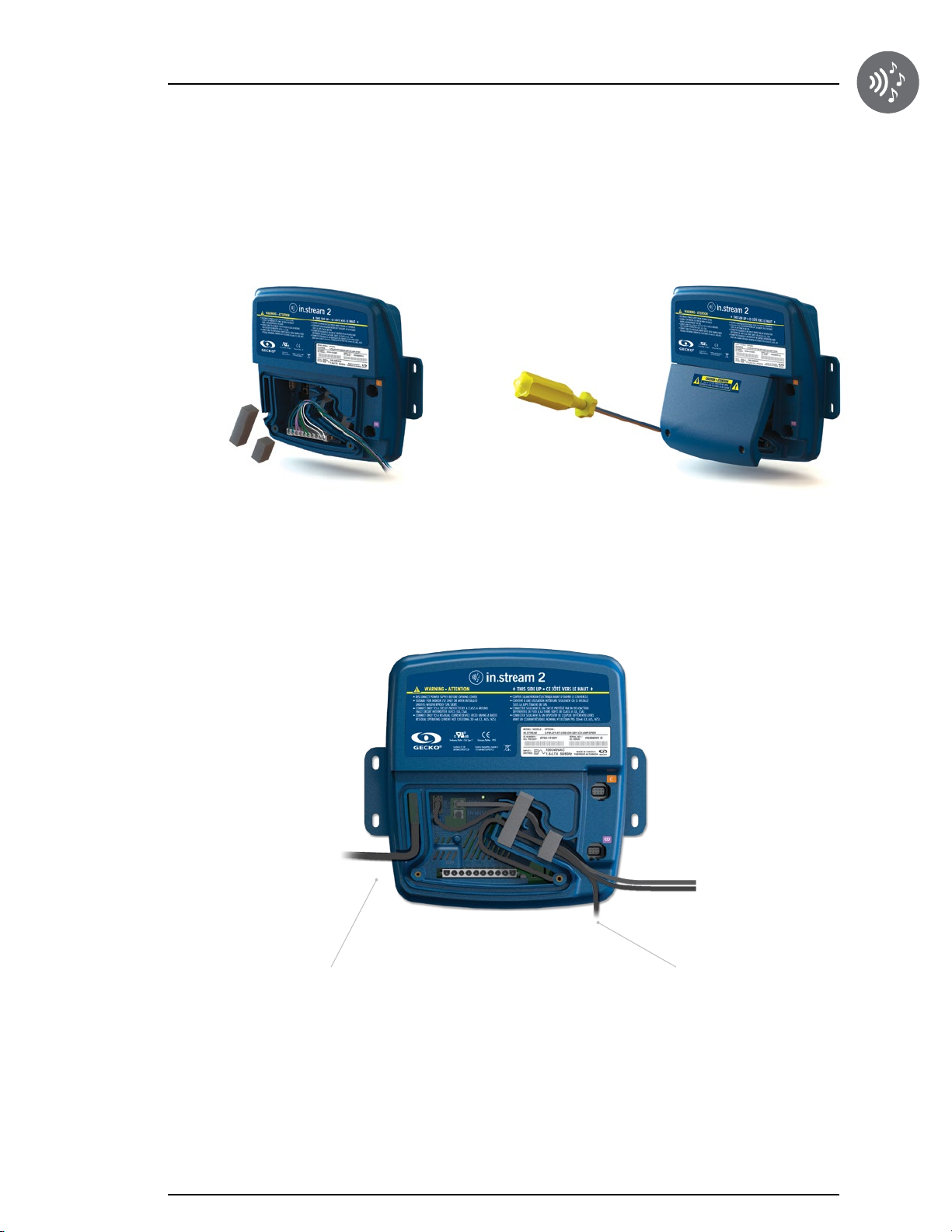
When all the audio cables are connected, put back the foam gaskets and the cover. Tighten the cover screws with the
Phillips screw driver ensuring you do not overtighten them.
Complete the cabling as follow:
AC Power input
Connect the AC power cable of the in.stream 2 to a direct
output of the spa pack. See the documentation related
to your specific pack model for more details on this
connection.
To CO Pack
Connect the CO cable of the in.stream 2 to the CO
connector of the spa pack. See the documentation related
to your specific pack model for more details on this
connection.
13
Page 15
Bluetooth overview
Pairing with a Bluetooth enabled device
The in.stream 2 can play music from any device equipped with Bluetooth wireless technologies, however, you must pair
your mobile device to the audio receiver in order to do so.
The system is ready to pair when it is not already connected to another device. To pair your device, make sure that you
are close enough to the in.stream 2, that it is turned on and that it is set in Bluetooth mode.
Note: In basic configuration (not connected to a keypad or controller), the in.stream 2 is set in Bluetooth mode. Otherwise, please refer
to your specific keypad operating manual for details on the in.stream 2 functions.
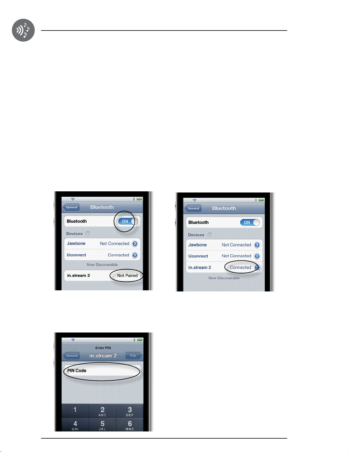
Follow these steps to pair your device
1. Open the Bluetooth settings on your device.
The location of the settings will depend on the device
you are using.
2. Make sure Bluetooth is on.
3. Select "in.stream 2" in the list of discoverable Bluetooth
devices detected nearby.
4. When prompted, enter 5555 as the PIN Code.
5. Once the pairing is done select in.stream 2 and when
connected is displayed the in.stream 2 will be ready to
start playing the selected audio.
Note: If the device moves out of range and loses connection,
it should reconnect automatically as soon as it is close enough.
This should happen without having to go through the menu
again.
The in.stream 2 will keep up to 8 devices in its memory. If one of
the last three connected devices is in range and has its Bluetooth
turned on, it will automatically connects with in.stream 2.
14
If multiple devices are within range and have already been paired
with the in.stream 2, priority will be given to the device that was
first detected in the in.stream 2 memory.
Page 16
Firmware update
The in.stream 2 firmware can be updated in the field. This is done using a USB flash disk inserted in the in.stream 2
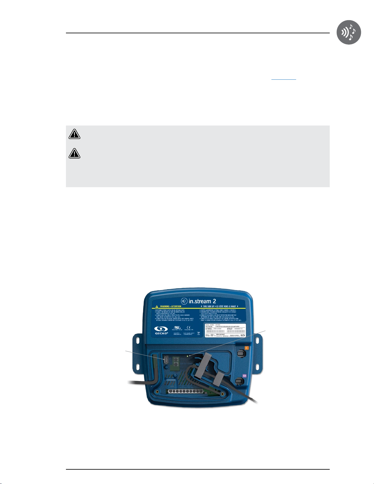
USB connector. The USB connector is accessible by removing the in.stream 2 cover. See the Connection section of the
user manual for details on removing the cover. See the following picture for the location of the USB connector.
Extract both folders from the provided "in.stream 2" archive and copy those folders (with their contents) on the root
directory of a USB flash disk with a capacity of 8GB to 32GB. Insert the USB flash disk in the in.stream 2 USB
connector and the process should start by itself. The status led should be checked to see what happens during the
update. See the following picture for the location of the status led.
Warning: Do not disconnect power to the in.stream 2 or remove the flash disk during firmware update since
this can make the in.stream 2 unbootable and it will be necessary to send it back in for repair.
Warning: At anytime, if a flash disk containning sofware update files is inserted into the USB connector,
always remove it while the power is ON, wait 5 seconds and then power off the system.
Attention: If the update process does not start or does not end, make sure to disconnect the flash disk prior
to power off the system and reboot to try the process again.
During all the software update process, the status led should be flashing, stop flashing and restart flashing several times.
Consider the update over when the status led stays solid ON for at least 20 seconds.
The process should take about 3 minutes to complete. After the update is finished, the in.stream 2 should operate using
the new firmware. Normally, a power on reset is not needed to reboot the system following the software update.
If the system does not start by itself, make sure to disconnect the flash disk and then just power off the system and
reboot it.
Status LED
USB connector
15
Page 17
Compatible keypads
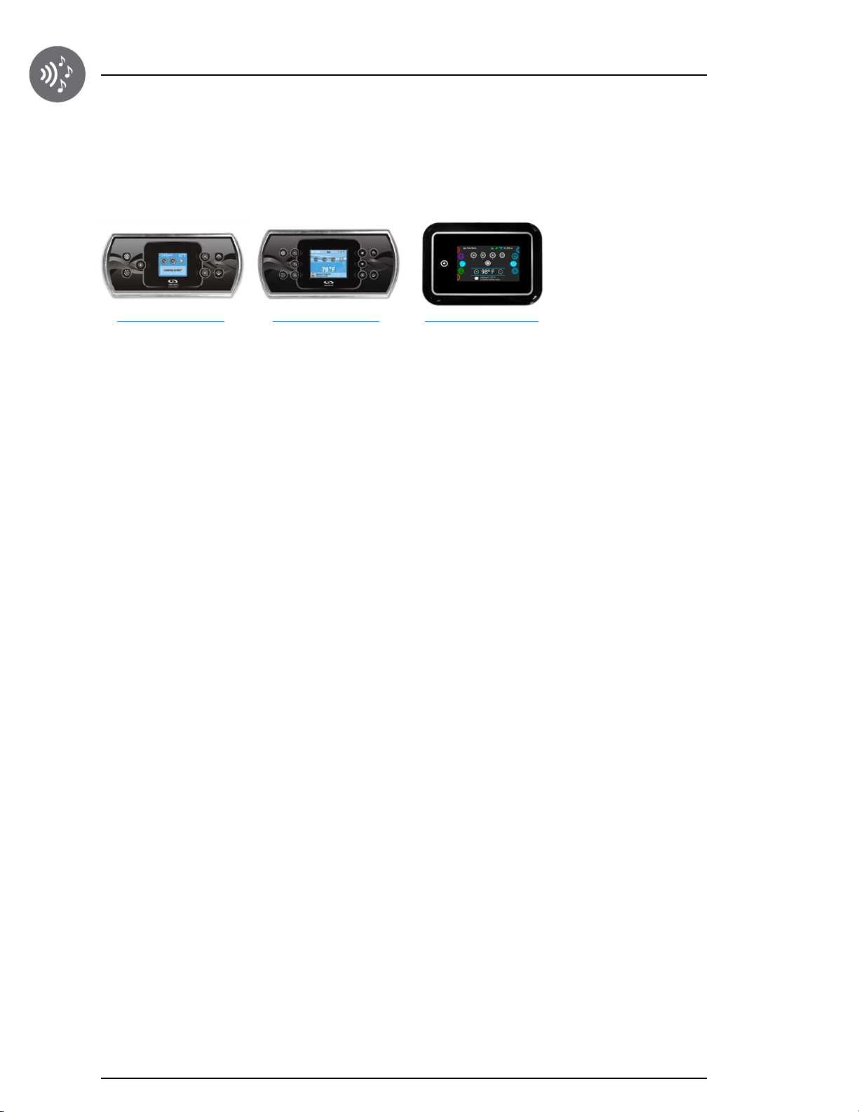
List of compatible keypads for the in.stream 2
For more information on the compatible keypads for your in.stream 2 refer to the corresponding Techbook.
in.k500 main keypad
Color LCD display, 7 keys
in.k800 main keypad
Color LCD display, 10 keys
in.k1000 main keypad
Color LCD capacitive
touchscreen display
16
Page 18

Regulatory statement
FCC Compliance Statement
Contains Transmitter Module FCC ID: A8TBM23SPKXYC2A
This device complies with Part 15 of the FCC Rules. Operation is subject to the following two conditions:
(1) this device may not cause harmful interference, and (2) this device must accept any interference received, including
interference that may cause undesired operation.
Note:
This equipment has been tested and found to comply with the limits for a Class B digital device, pursuant to part 15 of
the FCC Rules. These limits are designed to provide reasonable protection against harmful interference in a residential
installation. This equipment generates, uses and can radiate radio frequency energy, and if not installed and used
in accordance with the instructions, may cause harmful interference to radio communications. However, there is no
guarantee that interference will not occur in a particular installation. If this equipment does cause harmful interference to
radio or television reception, which can be determined by turning the equipment off and on, the user is encouraged to
try to correct the interference by one or more of the following measures:
• Reorient or relocate the receiving antenna.
• Increase the separation between the equipment and receiver.
• Connect the equipment into an outlet on a circuit different from that to which the receiver is connected.
• Consult the dealer or an experienced radio/TV technician for help.
Caution: To assure continued compliance, any changes or modifications not expressly approved by the party
responsible for compliance could void the user’s authority to operate this equipment.
FCC RF Exposure Statement
The device has been evaluated to meet general RF exposure requirement. The device can be used in portable exposure
condition without restriction.
IC Compliance Statement
Contains transmitter module IC: 12246A-BM23SPKXYC2
This device complies with Industry Canada licence-exempt RSS standard(s). Operation is subject to the following two
conditions: (1) this device may not cause interference, and (2) this device must accept any interference, including
interference that may cause undesired operation of the device.
Caution: To assure continued compliance, any changes or modifications not expressly approved by the party
responsible for compliance could void the user’s authority to operate this equipment.
RSS-102 RF Exposure Statement
This equipment complies with Industry Canada radiation exposure limits set forth for an uncontrolled environment.
17
Page 19

Specifications
Environmental ratings
Operating temperature: -4 °F (-20 °C) to 140 °F (60 °C)
Storage temperature: -22 °F (-30 °C) to 185 °F (85 °C)
Humidity: 70% max
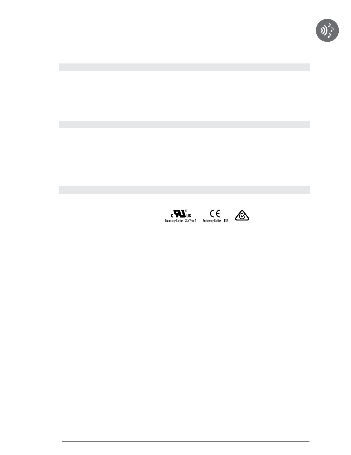
Water resistance: IPx5
Mechanical
Weight: 3.6 lb (1.64 Kg)
Dimensions (W x H x D): 9.81'' x 2.58'' x 8.88'' (249 x 65 x 226 mm)
Line input
Input voltage: 100-240VAC 50/60 Hz
Audio outputs
Maximum number of speakers: 4
Maximum number of subwoofer: 1
Audio amplifier type: Class D
Output power (speaker output): 25 W
Output power (subwoofer): 50 W
Output impedance (speaker): 4-8 Ohms
Output impedance (subwoofer): 2-4 Ohms
Harmonic distortion (speaker): 0.015% at 1 W (1 KHz)
Harmonic distortion (subwoofer): 0.015% at 1 W (100 Hz)
Frequency response (speaker): 5 Hz to 20 KHz
Frequency response (subwoofer): 10 Hz to 200 Hz
RMS
, 50 W peak
RMS
, 100 W peak
18
Auxiliary inputs
Maximum number of inputs: 1
Connection type: 1/8'' (3.5 mm) stereo jack
Maximum voltage: 2.2 Vpp
Impedance: 100 Kohms
FM receiver
Frequency band: 87.5-107.9 MHz
RF sensitivity: 2.2 μV
Harmonic distortion: 0.1% à 1 KHz
Frequency response: 30Hz à 15 KHz
FM decoder: Stereo Multiplex
Antenna type: 1 m (39'') cable
Antenna Connector: 1/8'' (3.5 mm) stereo jack
Page 20
Specifications
Bluetooth receiver
Frequency band: 2400 MHz to 2483.5 MHz
Transmit power: Class 2, 4 dBm
Bluetooth version: Bluetooth v4.1
Antenna type: Modular integrated
Profiles supported: A2DP, AVRCP
USB player
Compatibility: USB 1.1, 2.0 and 3.0
File format support: MP3 (files on the root)
Disk size: 8GB to 32GB
Disk format: FAT32
Cluster size: 4 Ko to 32 Ko
Connector type: USB type A
Applicable standards
UL 60065
CAN/CSA-C22.2 No. 60065-03
EN 60065
AS/NZS 60065
The in.stream is compliant with the Radio Equipment Directive (RED)
19
Page 21

9919-101311-E
Rev. 06-2016
© Groupe Gecko Alliance inc., 2016
All trademarks or registered trademarks
are the property of their respective owners.
450 des Canetons, Québec (Qc), G2E 5W6 Canada, 1.800.78.GECKO
Gecko Alliance
www.geckoalliance.com
Printed in Canada
 Loading...