

Page 1
GE Healthcare
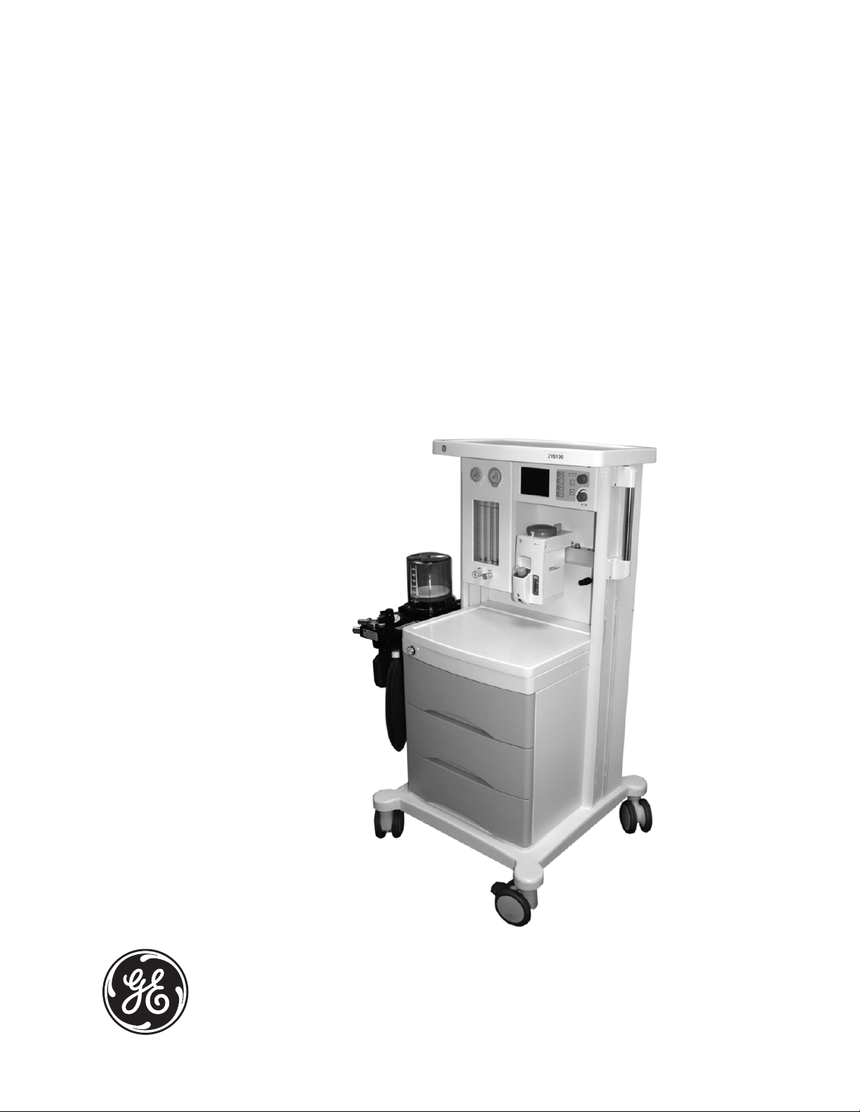
ZY9100 Anesthesia Machine
Technical Reference Manual
Page 2

ZY9100
ZY9100 is a registered trademark of GE Healthcare.
Other brand names or product names used in this manual are trademarks or
registered trademarks of their respective holders.
M1170718
Page 3

Technical Reference Manual
ZY9100 Anesthesia Machine
This document is not to be reproduced in any manner, nor are the contents to
be disclosed to anyone, without the express authorization of the product
service department, GE Healthcare, Ohmeda Drive, PO Box 7550, Madison,
Wisconsin, 53707.
© 2009 GE Healthcare
M1170718 i
Page 4

ZY9100
Important
The information contained in this technical reference manual pertains only to
those models of products which are marketed by GE Healthcare as of the
effective date of this manual or the latest revision thereof. This Technical
Reference manual was prepared for exclusive use by GE Healthcare service
personnel in light of their training and experience as well as the availability to
them of parts, proper tools and test equipment. Consequently, GE Healthcare
provides this Technical Reference manual to its customers purely as a
business convenience and for the customer's general information only without
warranty of the results with respect to any application of such information.
Furthermore, because of the wide variety of circumstances under which
maintenance and repair activities may be performed and the unique nature of
each individual's own experience, capacity, and qualifications, the fact that
customer has received such information from GE Healthcare does not imply
in any way that GE Healthcare deems said individual to be qualified to
perform any such maintenance or repair service. Moreover, it should not be
assumed that every acceptable test and safety procedure or method,
precaution, tool, equipment or device is referred to within, or that abnormal or
unusual circumstances, may not warrant or suggest different or additional
procedures or requirements.
This manual is subject to periodic review, update and revision. Customers are
cautioned to obtain and consult the latest revision before undertaking any
service of the equipment. Comments and suggestions on this manual are
invited from our customers. Send your comments and suggestions to the
Manager of Technical Communications, GE Healthcare, Ohmeda Drive, PO
Box 7550, Madison, Wisconsin 53707.
CAUTION Servicing of this product in accordance with this technical
reference manual should never be undertaken in the absence of
proper tools, test equipment and the most recent revision to this
service manual which is clearly and thoroughly understood.
Technical Competence
The procedures described in this technical reference manual should be
performed by trained and authorized personnel only. Maintenance should
only be undertaken by competent individuals who have a general knowledge
of and experience with devices of this nature. No repairs should ever be
undertaken or attempted by anyone not having such qualifications.
GE Healthcare strongly recommends using only genuine replacement parts,
manufactured or sold by GE Healthcare for all repair parts replacements.
Read completely through each step in every procedure before starting the
procedure; any exceptions may result in a failure to properly and safely
complete the attempted procedure.
ii M1170718
Page 5

1 Introduction
Table of Contents
Important . . . . . . . . . . . . . . . . . . . . . . . . . . . . . . . . . . . . . . . 1-ii
Technical Competence . . . . . . . . . . . . . . . . . . . . . . . . . . . . 1-ii
1.1 What this manual includes . . . . . . . . . . . . . . . . . . . . . . . 1-2
1.2 Standard service procedures . . . . . . . . . . . . . . . . . . . . . 1-3
1.2.1 User’s Reference Manual . . . . . . . . . . . . . . . . . . . 1-3
1.2.2 Software versions . . . . . . . . . . . . . . . . . . . . . . . . .1-3
1.2.3 Ventilator tests . . . . . . . . . . . . . . . . . . . . . . . . . . . 1-3
1.3 What is a ZY9100? . . . . . . . . . . . . . . . . . . . . . . . . . . . . 1-4
1.4 Configuration options . . . . . . . . . . . . . . . . . . . . . . . . . . . 1-5
1.4.1 Standard configuration . . . . . . . . . . . . . . . . . . . . . 1-5
1.4.2 Options . . . . . . . . . . . . . . . . . . . . . . . . . . . . . . . . . 1-5
1.5 System components . . . . . . . . . . . . . . . . . . . . . . . . . . . 1-6
2 Theory of Operation
1.6 Symbols used in the manual or on the equipment . . . . . 1-9
2.1 Theory overview . . . . . . . . . . . . . . . . . . . . . . . . . . . . . . 2-3
2.2 Gas flow through the anesthesia machine . . . . . . . . . . . 2-4
2.2.1 Overview . . . . . . . . . . . . . . . . . . . . . . . . . . . . . . . .2-6
2.2.2 Power switch . . . . . . . . . . . . . . . . . . . . . . . . . . . . . 2-6
2.2.3 Flow control . . . . . . . . . . . . . . . . . . . . . . . . . . . . . . 2-7
2.2.4 Hypoxic guard system . . . . . . . . . . . . . . . . . . . . . . 2-7
2.3 Flow through the breathing system . . . . . . . . . . . . . . . . 2-8
2.3.1 Overview of flow paths . . . . . . . . . . . . . . . . . . . . . 2-8
2.3.2 Manual ventilation . . . . . . . . . . . . . . . . . . . . . . . . . 2-8
2.3.3 Mechanical ventilation . . . . . . . . . . . . . . . . . . . . . . 2-9
2.4 ZY9100 Ventilator . . . . . . . . . . . . . . . . . . . . . . . . . . . . 2-10
2.4.1 Features . . . . . . . . . . . . . . . . . . . . . . . . . . . . . . . 2-10
2.4.2 Safety features . . . . . . . . . . . . . . . . . . . . . . . . . . 2-10
2.5 ZY9100 Ventilator components . . . . . . . . . . . . . . . . . . 2-11
2.5.1 Ventilator control electronics . . . . . . . . . . . . . . . . 2-11
2.5.2 Control panel and display . . . . . . . . . . . . . . . . . .2-11
M1170718 1
Page 6

ZY9100
3 Checkout Procedure
2.5.3 Pneumatic vent engine . . . . . . . . . . . . . . . . . . . . 2-12
2.6 Electrical . . . . . . . . . . . . . . . . . . . . . . . . . . . . . . . . . . . 2-13
2.6.1 Power supply . . . . . . . . . . . . . . . . . . . . . . . . . . .2-14
2.6.2 Alarm and signal switch . . . . . . . . . . . . . . . . . . . 2-15
2.6.3 Display . . . . . . . . . . . . . . . . . . . . . . . . . . . . . . . . 2-16
2.6.4 Control . . . . . . . . . . . . . . . . . . . . . . . . . . . . . . . . 2-17
2.7 Pneumatic subsystems . . . . . . . . . . . . . . . . . . . . . . . . 2-18
2.7.1 Pressure regulators . . . . . . . . . . . . . . . . . . . . . . . 2-19
2.7.2 Solenoid valve and VT control valve . . . . . . . . . . 2-19
2.7.3 Pop-off valve . . . . . . . . . . . . . . . . . . . . . . . . . . . . 2-20
2.7.4 Flow sensor adapter . . . . . . . . . . . . . . . . . . . . . .2-20
2.8 RS-232 Communication protocol . . . . . . . . . . . . . . . . . 2-21
3.1 Post-service checkout . . . . . . . . . . . . . . . . . . . . . . . . . . 3-3
3.2 Inspect the system . . . . . . . . . . . . . . . . . . . . . . . . . . . . . 3-4
3.3 Power failure test . . . . . . . . . . . . . . . . . . . . . . . . . . . . . . 3-5
3.4 Pipeline and cylinder tests . . . . . . . . . . . . . . . . . . . . . . . 3-6
3.5 Safety pressure relief valve test . . . . . . . . . . . . . . . . . . . 3-7
3.6 Flow control tests . . . . . . . . . . . . . . . . . . . . . . . . . . . . . . 3-8
3.7 O2 supply alarm test . . . . . . . . . . . . . . . . . . . . . . . . . . 3-10
3.8 Flush flow test . . . . . . . . . . . . . . . . . . . . . . . . . . . . . . . 3-11
3.9 Vaporizer back pressure test . . . . . . . . . . . . . . . . . . . . 3-12
3.10 Low-pressure leak test . . . . . . . . . . . . . . . . . . . . . . . . 3-13
3.11 Alarm tests . . . . . . . . . . . . . . . . . . . . . . . . . . . . . . . . . 3-16
3.12 Breathing system tests . . . . . . . . . . . . . . . . . . . . . . . 3-18
3.12.1 Check valves . . . . . . . . . . . . . . . . . . . . . . . . . . . 3-18
3.12.2 Ventilator bellows . . . . . . . . . . . . . . . . . . . . . . . 3-18
3.12.3 Bag circuit . . . . . . . . . . . . . . . . . . . . . . . . . . . . . 3-18
3.12.4 APL Valve . . . . . . . . . . . . . . . . . . . . . . . . . . . . . 3-18
3.13 Electrical safety tests . . . . . . . . . . . . . . . . . . . . . . . . . 3-20
4 Service Tests and Calibration
4.1 Cylinder regulators . . . . . . . . . . . . . . . . . . . . . . . . . . . . . 4-2
4.1.1 Test setup . . . . . . . . . . . . . . . . . . . . . . . . . . . . . . . 4-2
2 M1170718
Page 7

4.2 Low-pressure regulators . . . . . . . . . . . . . . . . . . . . . . . . 4-7
4.3 Hypoxic guard calibration . . . . . . . . . . . . . . . . . . . . . . . . 4-8
4.4 Airway pressure gauge . . . . . . . . . . . . . . . . . . . . . . . . . 4-9
4.5 Parameter calibration . . . . . . . . . . . . . . . . . . . . . . . . . . 4-11
5 Installation and Maintenance
Table of Contents
4.1.2 Testing cylinder regulators . . . . . . . . . . . . . . . . . . 4-3
4.1.3 Adjusting cylinder regulators . . . . . . . . . . . . . . . . . 4-6
4.2.1 Testing and adjusting low- pressure regulators . . 4-7
4.4.1 Zero the pressure gauge . . . . . . . . . . . . . . . . . . . . 4-9
4.4.2 Checking the pressure gauge accuracy . . . . . . . 4-10
4.5.1 System calibration . . . . . . . . . . . . . . . . . . . . . . . . 4-11
4.5.2 Paw calibration . . . . . . . . . . . . . . . . . . . . . . . . . . 4-12
4.5.3 VT calibration . . . . . . . . . . . . . . . . . . . . . . . . . . . 4-13
4.5.4 Calibration of inspired O2% . . . . . . . . . . . . . . . . 4-14
6 Troubleshooting
7 Software Installation
8 Repair Procedures
5.1 ZY9100 Installation checklist . . . . . . . . . . . . . . . . . . . . . 5-2
5.2 ZY9100 Planned maintenance . . . . . . . . . . . . . . . . . . . 5-3
6.1 General troubleshooting . . . . . . . . . . . . . . . . . . . . . . . .6-2
6.2 Breathing system leak test guide . . . . . . . . . . . . . . . . . . 6-4
6.2.1 Breathing system leak test . . . . . . . . . . . . . . . . . . 6-4
6.3 Ventilator troubleshooting instructions . . . . . . . . . . . . . . 6-6
6.4 Alarm messages . . . . . . . . . . . . . . . . . . . . . . . . . . . . . . 6-7
6.5 Mechanical/Electrical troubleshooting guide . . . . . . . . . 6-9
7.1 Firmware replacement procedure . . . . . . . . . . . . . . . . . 7-2
8.1 How to bleed gas pressure from the machine . . . . . . . . 8-4
8.2 How to remove the back panels . . . . . . . . . . . . . . . . . . . 8-5
8.2.1 Upper back panel . . . . . . . . . . . . . . . . . . . . . . . . . 8-5
8.2.2 Lower back panel . . . . . . . . . . . . . . . . . . . . . . . . . 8-5
8.3 How to remove the table top panel . . . . . . . . . . . . . . . . 8-6
8.4 Replace pipeline inlet filter and check valve . . . . . . . . . 8-7
8.5 Service the cylinder supply modules . . . . . . . . . . . . . . . 8-8
M1170718 3
Page 8

ZY9100
8.5.1 Tightening procedure for high-pressure tube fittings
8-8
8.5.2 Replace high- pressure regulator module (complete
replacement) . . . . . . . . . . . . . . . . . . . . . . . . . . . . . . . . .8-8
8.5.3 Replace cylinder inlet filter . . . . . . . . . . . . . . . . . . 8-9
8.5.4 Replace cylinder check valve . . . . . . . . . . . . . . . . 8-9
8.6 Replace system switch assembly . . . . . . . . . . . . . . . . 8-10
8.7 Service flowmeter module . . . . . . . . . . . . . . . . . . . . . . 8-11
8.8 Service vaporizer manifold parts . . . . . . . . . . . . . . . . . 8-12
8.8.1 Repair manifold port valve . . . . . . . . . . . . . . . . . 8-12
8.8.2 Checkout procedure for manifold port valve . . . . 8-12
8.8.3 Replace common gas check valve . . . . . . . . . . . 8-13
8.8.4 Replace vaporizer manifold . . . . . . . . . . . . . . . .8-13
8.9 Replace APL valve . . . . . . . . . . . . . . . . . . . . . . . . . . . 8-14
8.10 Replace Manual/Mechanical ventilation switch . . . . . 8-15
8.10.1 Replace Manual/Mechanical ventilation switch . 8-15
8.10.2 Replace switch shaft . . . . . . . . . . . . . . . . . . . . . 8-15
8.10.3 Test in manual ventilation mode . . . . . . . . . . . . 8-17
8.10.4 Test in mechanical ventilation mode . . . . . . . . . 8-17
8.11 Replace the disc seat of inspiratory/expiratory check
valves . . . . . . . . . . . . . . . . . . . . . . . . . . . . . . . . . . . . . . . . . 8-18
8.11.1 Replace the disc seat of inspiratory/expiratory check
valves . . . . . . . . . . . . . . . . . . . . . . . . . . . . . . . . . . . . . . 8-18
8.11.2 Check Valve Test . . . . . . . . . . . . . . . . . . . . . . . 8-18
8.12 Replace casters . . . . . . . . . . . . . . . . . . . . . . . . . . . . . 8-19
8.13 Replace task light and switch . . . . . . . . . . . . . . . . . . . 8-20
8.14 Electrical enclosure components . . . . . . . . . . . . . . . . 8-21
8.14.1 Charge board . . . . . . . . . . . . . . . . . . . . . . . . . .8-22
8.14.2 Power supply . . . . . . . . . . . . . . . . . . . . . . . . . .8-22
8.14.3 Battery . . . . . . . . . . . . . . . . . . . . . . . . . . . . . . . . 8-22
8.15 Replace the membrane of exhalation valve . . . . . . . . 8-24
9 Illustrated Parts
9.1 Service tools . . . . . . . . . . . . . . . . . . . . . . . . . . . . . . . . . 9-3
9.1.1 Test devices . . . . . . . . . . . . . . . . . . . . . . . . . . . . . 9-3
9.1.2 Lubricants and adhesives . . . . . . . . . . . . . . . . . . . 9-3
4 M1170718
Page 9

Table of Contents
9.1.3 Test tools . . . . . . . . . . . . . . . . . . . . . . . . . . . . . . . 9-3
9.2 External components - front view . . . . . . . . . . . . . . . . . . 9-4
9.3 External components - rear view . . . . . . . . . . . . . . . . . . 9-5
9.4 Flow meter and gauges . . . . . . . . . . . . . . . . . . . . . . . . . 9-6
9.5 Rear panel components . . . . . . . . . . . . . . . . . . . . . . . . . 9-7
9.6 Display cables, board, assemblies . . . . . . . . . . . . . . . . . 9-8
9.7 AC power components . . . . . . . . . . . . . . . . . . . . . . . . 9-10
9.8 Circuit board assemblies . . . . . . . . . . . . . . . . . . . . . . . 9-11
9.8.1 Software version . . . . . . . . . . . . . . . . . . . . . . . . . 9-12
9.9 Pipeline inlet fittings . . . . . . . . . . . . . . . . . . . . . . . . . . . 9-13
9.10 Cylinder gas supplies . . . . . . . . . . . . . . . . . . . . . . . . . 9-14
9.11 Vaporizer and vaporizer manifold . . . . . . . . . . . . . . . 9-15
9.12 Components under table . . . . . . . . . . . . . . . . . . . . . . 9-16
9.13 Breathing circuit and interface . . . . . . . . . . . . . . . . . . 9-17
10 Schematics and Diagrams
11 System Specifications
9.13.1 Absorber canister . . . . . . . . . . . . . . . . . . . . . . . 9-18
9.13.2 Absorber Canister Interface Module . . . . . . . . . 9-19
9.13.3 Manual/Mechanical ventilation switch . . . . . . . . 9-20
9.13.4 Bellows assembly . . . . . . . . . . . . . . . . . . . . . . . 9-21
9.14 Legris quick-release fittings . . . . . . . . . . . . . . . . . . . . 9-22
9.15 Vent drive and low-pressure tubing . . . . . . . . . . . . . . 9-23
9.16 Tubing for use with Legris fittings . . . . . . . . . . . . . . . 9-24
9.17 Cables and harnesses . . . . . . . . . . . . . . . . . . . . . . . . 9-25
10.1 Pneumatic circuit diagram . . . . . . . . . . . . . . . . . . . . . 10-2
10.2 Electrical cabling block diagram . . . . . . . . . . . . . . . . . 10-4
10.3 Tubing diagram . . . . . . . . . . . . . . . . . . . . . . . . . . . . . 10-5
11.1 Pneumatic specifications . . . . . . . . . . . . . . . . . . . . . . 11-2
11.1.1 Gas supplies . . . . . . . . . . . . . . . . . . . . . . . . . . . 11-2
11.1.2 Flow . . . . . . . . . . . . . . . . . . . . . . . . . . . . . . . . . 11-2
11.2 Electrical power specifications . . . . . . . . . . . . . . . . . . 11-3
11.3 Breathing system specifications . . . . . . . . . . . . . . . . . 11-4
11.4 Gas scavenging specifications . . . . . . . . . . . . . . . . . . 11-5
M1170718 5
Page 10

ZY9100
11.5 Physical specifications . . . . . . . . . . . . . . . . . . . . . . . . 11-5
11.6 Environmental specifications . . . . . . . . . . . . . . . . . . . 11-6
11.7 Ventilator operating specifications . . . . . . . . . . . . . . . 11-7
11.7.1 Oxygen . . . . . . . . . . . . . . . . . . . . . . . . . . . . . . . 11-7
11.8 Ventilator accuracy data . . . . . . . . . . . . . . . . . . . . . . 11-8
6 M1170718
Page 11

1 Introduction
In this section 1.1 What this manual includes . . . . . . . . . . . . . . . . . . . . . . . 1-2
1.2 Standard service procedures . . . . . . . . . . . . . . . . . . . . . 1-3
1.2.1 User’s Reference Manual . . . . . . . . . . . . . . . . . . . 1-3
1.2.2 Software versions . . . . . . . . . . . . . . . . . . . . . . . . .1-3
1.2.3 Ventilator tests . . . . . . . . . . . . . . . . . . . . . . . . . . . 1-3
1.3 What is a ZY9100? . . . . . . . . . . . . . . . . . . . . . . . . . . . . 1-4
1.4 Configuration options . . . . . . . . . . . . . . . . . . . . . . . . . . . 1-5
1.4.1 Standard configuration . . . . . . . . . . . . . . . . . . . . . 1-5
1.4.2 Options . . . . . . . . . . . . . . . . . . . . . . . . . . . . . . . . . 1-5
1.5 System components . . . . . . . . . . . . . . . . . . . . . . . . . . . 1-6
1.6 Symbols used in the manual or on the equipment . . . . . 1-9
M1170718 1-1
Page 12

ZY9100
1.1 What this manual includes
This manual covers the service information for the ZY9100
anesthesia machine and ventilator. It details the following
components:
• Ventilator
• Gas delivery
• Breathing system
•Frame
1-2 M1170718
Page 13

1.2 Standard service procedures
1 Introduction
1.2.1 User’s
Reference Manual
1.2.2 Software versions
Some sections of this manual refer you to the User’s Reference
Manual for the ZY9100 anesthesia machine. To expedite repairs, you
must have and be familiar with the User’s Reference Manual.
Refer to the User’s Reference Manual for further information about
the operation of the system.
The revision level is displayed on the ventilator startup menu. This
manual includes test and calibration procedures for Revision 3.x
software.
1.2.3 Ventilator tests Service calibration functions let GE Healthcare trained users and
service personnel perform ventilator setup functions, tests,
calibration, and measurements from the front panel display.
Normal operational tests, calibration, and troubleshooting can be
performed on your ventilator without removing components from the
system. Repair may require removing the ventilator components from
the anesthesia machine.
WARNING Section 4, “Service Tests and Calibration” must be
performed whenever an internal component of the
ventilator is accessed to verify that all critical parts of the
ventilator are still operational and within specification.
WARNING After the ventilator has been serviced, perform Section 3
“Checkout Procedure” to verify the entire Anesthesia
System is functioning properly before the system can be
returned to clinical use.
M1170718 1-3
Page 14

ZY9100
1.3 What is a ZY9100?
Note Configurations available for this product depend on local market and
The ZY9100 anesthesia machine is developed and manufactured by
GE Healthcare. It is a mobile anesthesia machine with anesthesia,
respiration, and monitoring integrated in a single unit. It can be used
to perform closed circuit or semi-closed circuit anesthesia and
respiration control for children and adults.
standards requirements. Illustrations in this manual may not
represent all configurations of the product. The ZY9100 product is not
suitable for use in an MRI environment.
1-4 M1170718
Page 15

1.4 Configuration options
1 Introduction
1.4.1 Standard configuration
The standard configuration includes the following items:
• Ventilator
• Vaporizer manifold (two vaporizer connections)
• Serial Interface - RS232
• Three large drawers
• Breathing circuit
1.4.2 Options Options include the following items:
• Gas cylinder configurations:
No cylinders
One O
Two O
One O
Note If configured for cylinders, one O
two N
• Gas scavenging (adjustable passive)
Model Vaporizer Equipped
ZY9100A1 One enflurane or isoflurane
ZY9100A2 One enflurane and one isoflurane
ZY9100B1 One enflurane or one isoflurane
ZY9100B2 One enflurane and one isoflurane
cylinder
2
cylinders
2
and one N2O cylinder
2
O cylinders.
2
is always required (cannot have
2
M1170718 1-5
Page 16
ZY9100
1
3
2
4
5
6
7
8
9
10
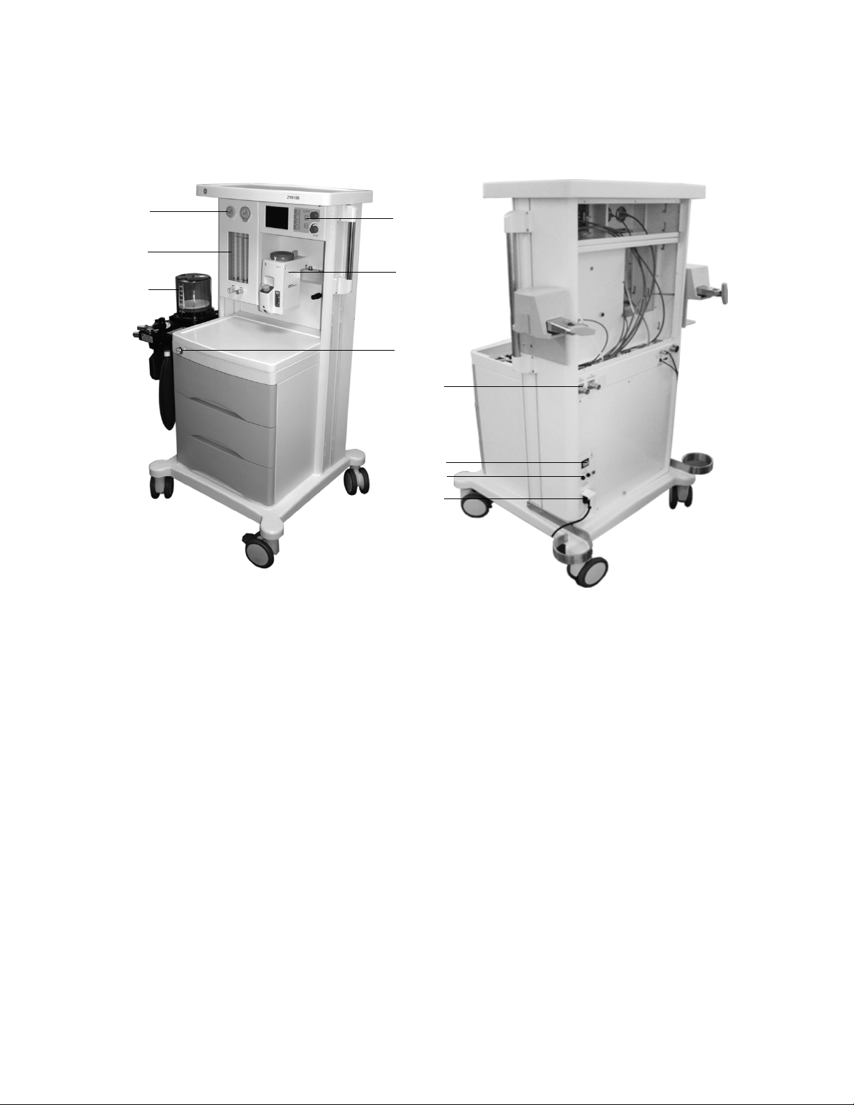
1.5 System components
1. Pipeline gas inlet port(s)
2. Fuse sockets
3. Power switch
4. Mains power inlet
5. System display
6. Vaporizer(s)
flush button
7. O
2
8. Breathing system
9. Flowmeters/flowtubes
10. Pressure gauge
Figure 1-1 • ZY9100 Anesthesia Machine
1-6 M1170718
Page 17
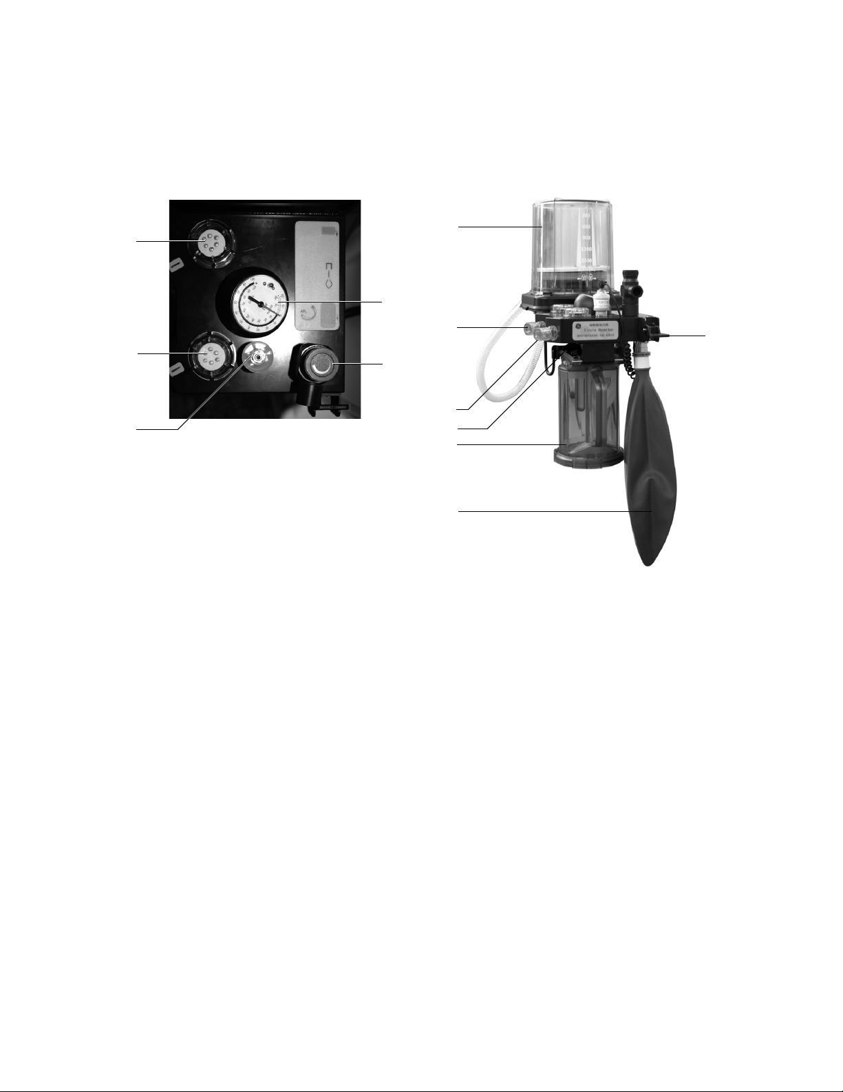
1. O2 sensor
3
1
5
4
11
10
7
6
9
12
8
2
2. Inspiratory check valve
3. Expiratory check valve
4. Airway pressure gauge
5. APL (adjustable pressure limiting) valve
6. Manual ventilation bag
7. Absorber canister
8. Canister release
9. Inspiratory port
10. Expiratory port
11. Bellows assembly
12. Manual/Mechanical ventilation switch
Figure 1-2 • ZY9100 Breathing System
M1170718 1-7
Page 18
ZY9100
4
3
1
2
5
6
7
8
9
10
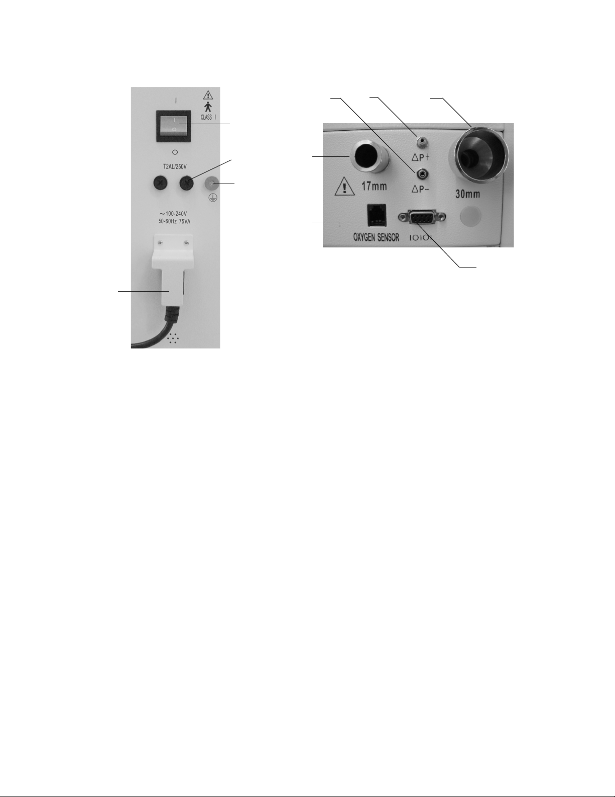
1. Flow transducer and patient airway pressure transducer port
2. Flow transducer and patient airway pressure transducer port
3. Exhaust gas outlet
4. Communications port
sensor socket
5. O
2
6. Drive gas port
7. Fuse sockets
8. Power switch
9. Equipotential connector
10. Mains power inlet
Figure 1-3 • ZY9100 Rear Panels
1-8 M1170718
Page 19
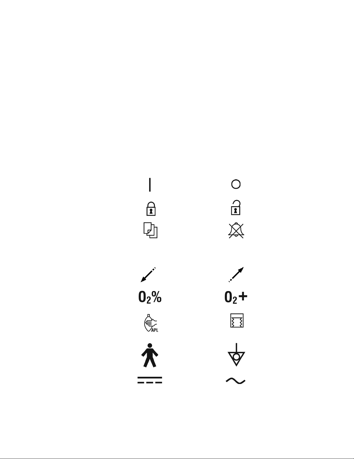
1.6 Symbols used in the manual or on the equipment
Warnings and cautions tell you about the dangerous conditions that
can occur if you do not follow all instructions in this manual. Read and
follow all warnings and cautions carefully.
WARNING Warnings tell about a condition that can cause injury to
the operator or the patient.
CAUTION Cautions tell about a condition that can cause damage to
the equipment.
A Note provides additional information, tips and recommendations.
Other symbols replace words on the equipment or in manuals. No
one device uses all of the symbols. These symbols include:
ON (power) OFF (power)
1 Introduction
FREQ
Lock Unlock
Menu Alarm silence
Breathing frequency
Inspiratory flow Expiratory flow
sensor connection O2 flush button
O
2
Manual ventilation mode Mechanical ventilation
Type B equipment Equipotential
I:E
Inspiratory-Expiratory Rate
mode
Direct current Alternating current
M1170718 1-9
Page 20
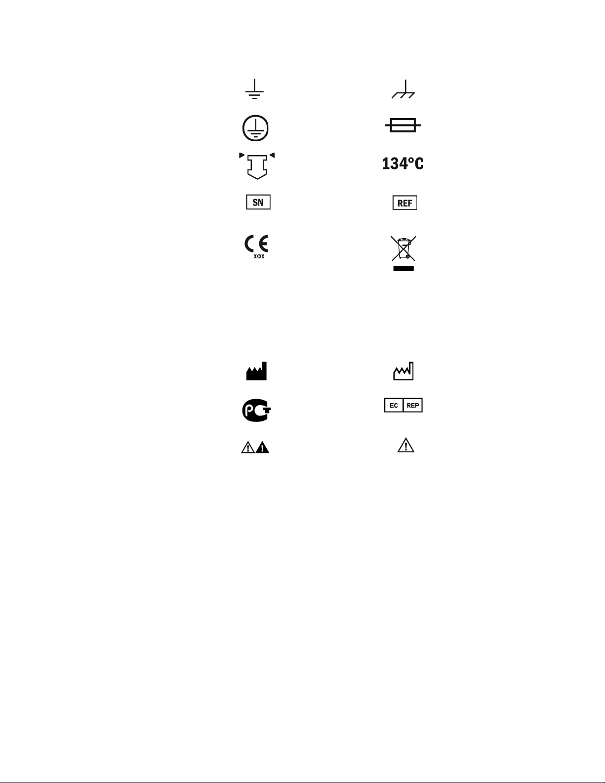
ZY9100
Earth ground Frame or chassis ground
Protective earth ground Fuse
Read top of the float Autoclavable
Serial Number Stock number
Systems with this mark
agree with the European
Council directive (93/42/
EEC) for Medical Devices
when they are used as
specified in their User’s
Reference manuals. The
xxx is the certification
number of the Notified
Body used by GE
Healthcare’s Quality
Systems.
Manufacturer Date of manufacture
GOST R Russian
certification
Attention, refer to product
instructions, IEC 60601-1
Indicates that the waste of
electrical and electronic
equipment must not be
disposed as unsorted
municipal waste and must
be collected separately.
Please contact an
authorized representative of
the manufacturer for
information concerning the
decommissioning of
equipment.
Authorized representative of
the European Community
Caution, ISO 7000-0434
1-10 M1170718
Page 21

2 Theory of Operation
In this section 2.1 Theory overview . . . . . . . . . . . . . . . . . . . . . . . . . . . . . . 2-3
2.2 Gas flow through the anesthesia machine . . . . . . . . . . . 2-4
2.2.1 Overview . . . . . . . . . . . . . . . . . . . . . . . . . . . . . . . .2-6
2.2.2 Power switch . . . . . . . . . . . . . . . . . . . . . . . . . . . . . 2-6
2.2.3 Flow control . . . . . . . . . . . . . . . . . . . . . . . . . . . . . . 2-7
2.2.4 Hypoxic guard system . . . . . . . . . . . . . . . . . . . . . . 2-7
2.3 Flow through the breathing system . . . . . . . . . . . . . . . . 2-8
2.3.1 Overview of flow paths . . . . . . . . . . . . . . . . . . . . . 2-8
2.3.2 Manual ventilation . . . . . . . . . . . . . . . . . . . . . . . . . 2-8
2.3.3 Mechanical ventilation . . . . . . . . . . . . . . . . . . . . . . 2-9
2.4 ZY9100 Ventilator . . . . . . . . . . . . . . . . . . . . . . . . . . . . 2-10
2.4.1 Features . . . . . . . . . . . . . . . . . . . . . . . . . . . . . . . 2-10
2.4.2 Safety features . . . . . . . . . . . . . . . . . . . . . . . . . . 2-10
2.5 ZY9100 Ventilator components . . . . . . . . . . . . . . . . . . 2-11
2.5.1 Ventilator control electronics . . . . . . . . . . . . . . . . 2-11
2.5.2 Control panel and display . . . . . . . . . . . . . . . . . .2-11
2.5.3 Pneumatic vent engine . . . . . . . . . . . . . . . . . . . . 2-12
2.6 Electrical . . . . . . . . . . . . . . . . . . . . . . . . . . . . . . . . . . . 2-13
M1170718 2-1
Page 22

ZY9100
2.6.1 Power supply . . . . . . . . . . . . . . . . . . . . . . . . . . .2-14
2.6.2 Alarm and signal switch . . . . . . . . . . . . . . . . . . . 2-15
2.6.3 Display . . . . . . . . . . . . . . . . . . . . . . . . . . . . . . . . 2-16
2.6.4 Control . . . . . . . . . . . . . . . . . . . . . . . . . . . . . . . . 2-17
2.7 Pneumatic subsystems . . . . . . . . . . . . . . . . . . . . . . . . 2-18
2.7.1 Pressure regulators . . . . . . . . . . . . . . . . . . . . . . . 2-19
2.7.2 Solenoid valve and VT control valve . . . . . . . . . . 2-19
2.7.3 Pop-off valve . . . . . . . . . . . . . . . . . . . . . . . . . . . . 2-20
2.7.4 Flow sensor adapter . . . . . . . . . . . . . . . . . . . . . .2-20
2.8 RS-232 Communication protocol . . . . . . . . . . . . . . . . . 2-21
2-2 M1170718
Page 23

2.1 Theory overview
2 Theory of Operation
This section describes:
• The flow of gas through the anesthesia machine.
• The flow of gas through the breathing system.
• Electrical connections and the function of electrical components.
• RS-232 communication protocol.
M1170718 2-3
Page 24
ZY9100
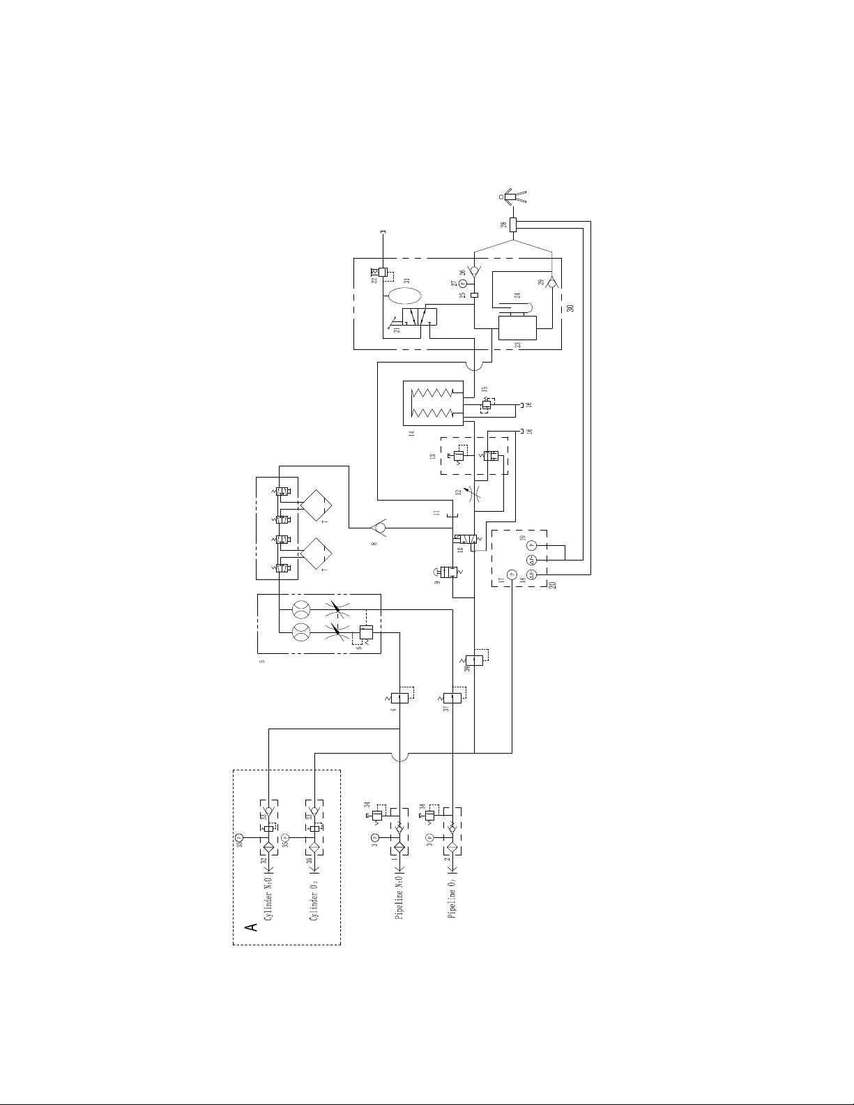
2.2 Gas flow through the anesthesia machine
2-4 M1170718
Page 25

1. N2O pipeline inlet
2. O2 pipeline inlet
3. Pipeline airway pressure gauge
2O pressure regulator
4. N
5. Flow control and mixer
proportional control (balance regulator)
6. O
2
7. Vaporizers
8. Fresh gas Check valve
2 flush valve
9. O
10. Solenoid valve
11. Fresh gas outlet
T control valve
12. V
13. Exhalation valve
14. Bellows assembly
15. Pop-off valve
16. Drive gas exhaust
17. Gas inlet pressure transducer
18. Flow sensor
19. Paw transducer
20. Control board
21. Manual/mechanical ventilation switch
22. APL valve
23. Absorber canister
24. Reservior
2 sensor
25. O
26. Inspiratory check valve
27. Pressure guage
28. Flow sensor adapter
29. Expiratory check valve
30. Breathing circuit
31. Manual ventilation bag
2O cylinder gas inlet valve
32. N
33. Check valve
34. Safety pressure relief valve
35. Cylinder gas pressure guage
2 cylinder gas inlet valve
36. O
37. Cylinder pressure regulator
38. Drive gas pressure regulator
Figure 2-1 • ZY9100 System pneumatic diagram
2 Theory of Operation
M1170718 2-5
Page 26

ZY9100
2.2.1 Overview
Gas supplies Gas enters the system through a pipeline or cylinder connection. All
connections have indexed fittings, filters, and check (one-way)
valves. Gauges show the cylinder and pipeline pressures.
A regulator decreases the cylinder pressures to the appropriate
system pressure. A pressure relief valve helps protect the system
from high pressures.
To help prevent problems with the gas supplies:
• Install yoke plugs on all empty cylinder connections.
• When a pipeline supply is connected, keep the cylinder valve
closed.
O2 flow O2 is supplied by regulated gas cylinders or the medical gas pipelines
in the hospital.A low-pressure regulator decreases the pressure for
the flush valve.
When pushed, the flush valve supplies high flows of O
common gas outlet.
A low-pressure regulator supplies a constant O
control valve.
A sensor on the main board monitors the O
pressure is too low, an alarm appears on the ventilator.
2
supply pressure. If the
2
N2O A hypoxic guard on the N2O and O2 flow control helps keep the O2
concentration higher than 25% at the common gas outlet.
A balance regulator controls the flow of N
Oxygen pressure at a control port adjusts the output of the regulator.
This stops flow during an O
hypoxic gas pressures decrease with the O
supply failure and ensures that the
2
O to the flow control valve.
2
supply pressure.
2
Mixed gas The mixed gas goes from the flowmeter outlet through the vaporizer
that is in use, through the common gas check valve, to the common
gas outlet, and into the breathing system. A pressure relief valve is
located between the common gas check valve and the common gas
outlet to prevent the delivery of high pressures to the breathing
system.
2.2.2 Power switch The power switch has two positions: On and Off.
In the Off position
The switch:
• Turns off the ventilator (electrical).
In the On position
The switch:
• Turns on the ventilator (electrical).
to the
2
pressure to the flow
2-6 M1170718
Page 27

2 Theory of Operation
2.2.3 Flow control Needle valves (one for each gas) adjust gas flow. Clockwise rotation
decreases flow. Counterclockwise increases flow. A hypoxic guard
system sets the maximum ratio of N
WARNING The hypoxic guard sets a minimum O2 concentration in
the common gas stream.
O to O2.
2
2.2.4 Hypoxic guard system
The hypoxic guard is an internal system that is not serviceable. It
helps control an approximate minimum 1 to 3 ratio of flow between O
and N
• An increase in N
• A decrease in O
Higher concentrations of O
not engaged: either by reducing the N
engagement or by increasing O
When the N
N
the guard is engaged, turning the N
(increase in N
(increase in O
O. When engaged the O2 and N2O knobs turn together:
2
O flow causes an increase in O2 flow.
2
flow causes a decrease in N2O flow.
2
are possible when the hypoxic guard is
2
O flow below the point of
2
flow above the point of engagement.
2
O flow is below the point of engagement, increasing the
2
O flow turns the O2 sprocket without changing the O2 flow. Once
2
O flow control counterclockwise
2
O flow) also turns the O2 knob counterclockwise
2
flow) to maintain a nominal 25% minimum O2
2
concentration.
Decreasing the N
sprocket away from the tab on the O
O flow from the engagement point rotates the O2
2
knob, increasing the O2 flow.
2
2
M1170718 2-7
Page 28

ZY9100
2.3 Flow through the breathing system
2.3.1 Overview of flow paths
This section looks at three types of flow paths. Refer to Figure 2-1 for
a graphic representation.
• Ventilation paths: How gas flows from the drive source (bag or
bellows) to and from the patient.
• Common gas paths: Common gas can flow from the machine
interface directly to the patient through the inspiratory check
valve, or through the absorber into the expiratory flow.
• Scavenged gas paths: APL or pop-off valve.
2.3.2 Manual ventilation
Manual inspiration The Manual/Mechanical ventilation switch on the breathing system
closes the ventilator path. Manual ventilation must be selected on the
display as well.
Gas flows from the bag into the breathing circuit module, and through
a unidirectional valve (inspiratory check valve) to the patient.
During inspiration, common gas flows from the machine into the
inspiratory limb, upstream of the inspiratory check valve.
Manual exhalation The Manual/Mechanical ventilation switch on the breathing system
keeps the ventilator path closed. Manual ventilation must be selected
on the display as well.
Gas flows from the patient, through the absorber, through a
unidirectional valve (expiratory check valve), and into the bag.
During exhalation, common gas flows backwards through the
Manual/Mechanical ventilation switch into the bag.
APL valve The APL valve sets a pressure limit for manual ventilation.
As the APL knob is turned, it puts more or less force on the APL disc
and seat. If the circuit pressure is too high, the disc and seat inside
the diaphragm opens and vents gas to the scavenging system.
2-8 M1170718
Page 29

2 Theory of Operation
2.3.3 Mechanical ventilation
Mechanical inspiration The Manual/Mechanical ventilation switch on the breathing system
closes the manual path. Pilot pressure closes the exhalation valve.
Mechanical ventilation must be selected on the display as well.
Drive gas pushes down on the outside of the bellows. Gas flows from
the inside of the bellows, through the absorber, and through a
unidirectional valve (inspiratory check valve) to the patient.
During inspiration, common gas flows into the inspiratory limb,
upstream of the inspiratory check valve.
Mechanical exhalation The Manual/Mechanical ventilation switch on the breathing system
keeps the manual path closed. Drive gas flow stops and the
exhalation valve opens. Exhaled gas flows from the patient, through a
unidirectional valve (expiratory check valve), through the absorber,
and into the bellows. Residual drive gas flows out of the bellows
housing to the scavenging system.
During exhalation, common gas flows backwards through the
Manual/Mechanical ventilation switch into the bellows.
Pop-off valve The pop-off valve limits the pressure inside the bellows to 2.5 cmH
above the drive gas pressure. This normally occurs when the bellows
reaches the top of the housing at the end of exhalation.
Excess gas vents to the scavenging port through the pop-off valve
and the exhalation valve.
O
2
M1170718 2-9
Page 30

ZY9100
2.4 ZY9100 Ventilator
2.4.1 Features • Sensors in the breathing circuit are used to monitor patient
The ZY9100 Ventilator is a microprocessor based, electronicallycontrolled, pneumatically-driven ventilator with built in monitoring
systems for inspired oxygen, airway pressure and exhaled volume.
The ventilator is designed to be used as a medical device assisting in
the delivery of anesthesia and is part of the ZY9100 Anesthesia
Machine.
ventilation and measure inspired oxygen concentration.
• User settings and microprocessor calculations control breathing
patterns.
• Mechanical ventilation is started by pushing the bellows key on
the display and selecting the bellows with the Manual/Mechanical
ventilation switch on the breathing system.
• An RS-232 serial digital communications port connects to and
communicates with external devices.
2.4.2 Safety features • Airway overpressure protection linked to the high Paw setting.
• Volume over-delivery limits.
• Proprietary hose connections and fixed manifolds.
• 150 psi burst overpressure protection.
2-10 M1170718
Page 31
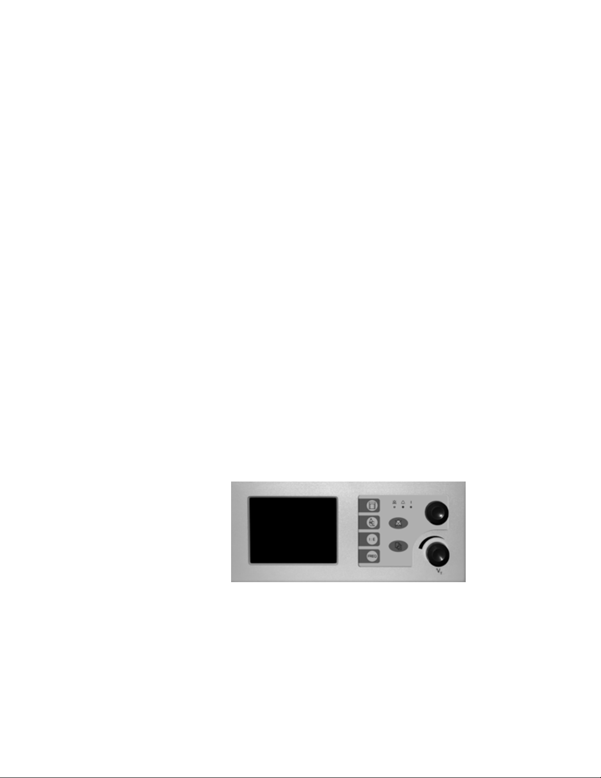
2.5 ZY9100 Ventilator components
Components of the ventilator are found in different locations on the
anesthesia machine. The ventilator package consists of:
• Ventilator display
• Pneumatic engine
• Ventilator control electronics
• Ventilator power supply
2 Theory of Operation
2.5.1 Ventilator
control electronics
2.5.2 Control panel and display
The ventilator power supply components are found in the electrical
enclosure at the back of the machine.
The ventilator power supply components include a 24 volt power
supply, charge board, and batteries.
The power supply receives AC power from the machine’s AC Inlet
module through inline fuses, and a separate line filter. It converts AC
power to DC power that feeds into the charge board.
All the power necessary to operate the ventilator and light package
comes from the power circuits. The digital circuits control the
operation of the ventilator.
Two 12 volt batteries provide backup power to operate the ventilator
in case of mains power failure.
The control panel on the ZY9100 Ventilator is mounted above the
mounting brackets for the vaporizer. The ventilator display includes
five submodules:
• The color liquid crystal display
• The keyboard front panel
• A rotary encoder (control knob)
• Inspiratory flow adjustment knob
Figure 2-2 • ZY9100 Display module
The keyboard and rotary encoder are used to control the operation of
the ventilator. The front panel uses a three step — selection, change,
and approve — setting scheme to prevent unwanted selections. The
speaker on the rear panel supplies audio alarms to the operator.
Primary controls are: ventilation mode, I:E ratio, respiratory frequency
(FREQ), and inspiratory flow (V
M1170718 2-11
).
T
Page 32
ZY9100
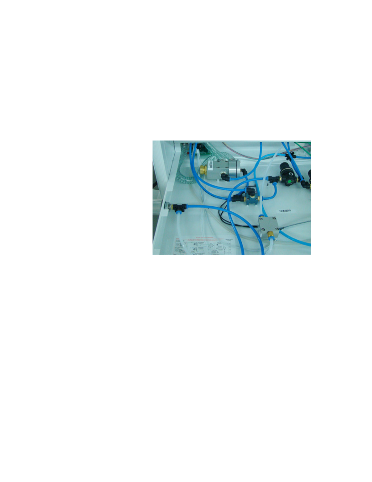
2.5.3 Pneumatic vent engine
The pneumatic vent engine consists of:
• Solenoid valve
• Flow control needle valve (V
• Exhalation/overpressure relief valve
The exhalation valve is usually open. During inspiration, gas pressure
supplied by the solenoid valve causes the exhalation valve to close.
During exhalation, the gas pressure is vented to scavenging allowing
the exhalation valve to open.
If the pressure of the gas is more than 60 cmH
relief valve opens.
)
T
O the overpressure
2
2-12 M1170718
Page 33
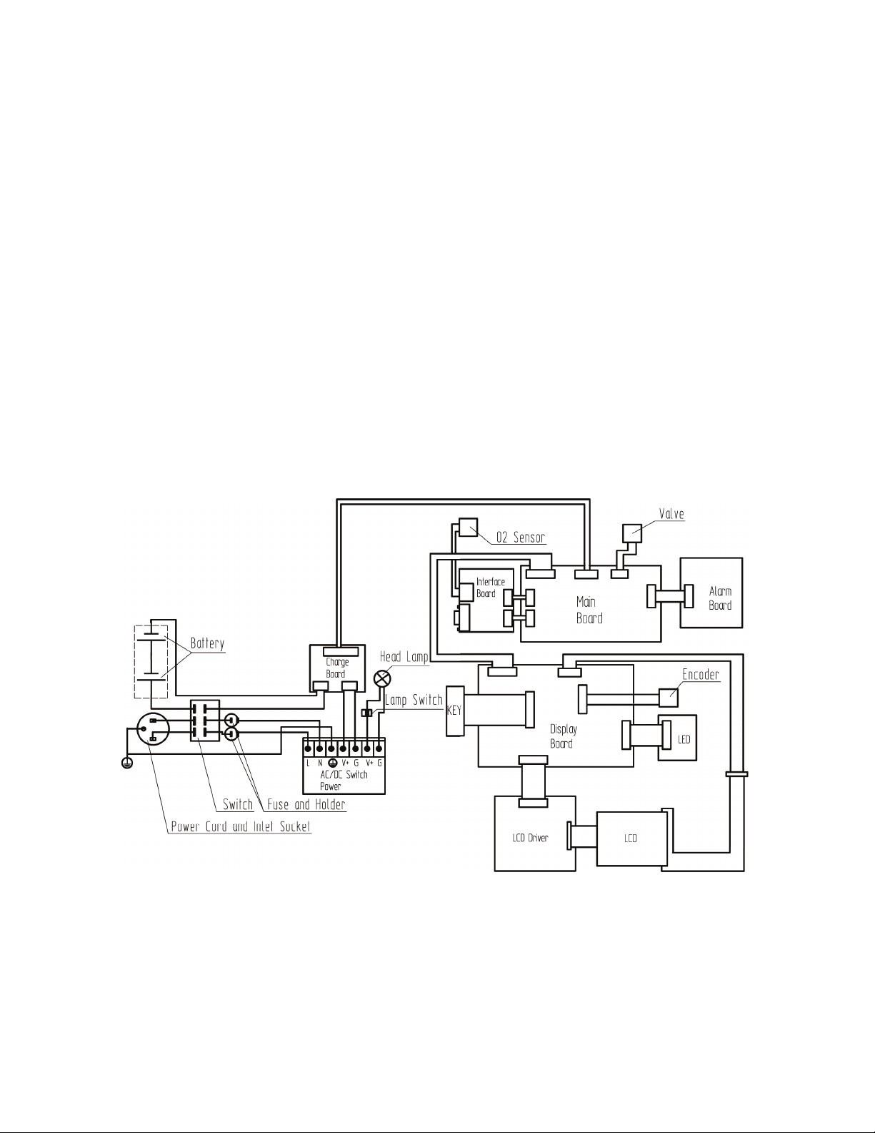
2.6 Electrical
2 Theory of Operation
The electrical systems perform their functions through the following
printed circuit boards:
• Main board
• Charge board
• Alarm board
• Interface board
• Top light board
• Display board
• Indicator board
• Driver board
• Inverter board
The ZY9100 anesthesia machine electrical system consists of:
• Display — This provides the user interface to the ventilator
software controls.
• Power — A switching power supply is used to convert
100-240VAC / 50Hz-60Hz mains power to 24V DC to power the
ventilator and to charge the back-up batteries.
Figure 2-3 • ZY9100 Electronic block diagram
M1170718 2-13
Page 34
ZY9100
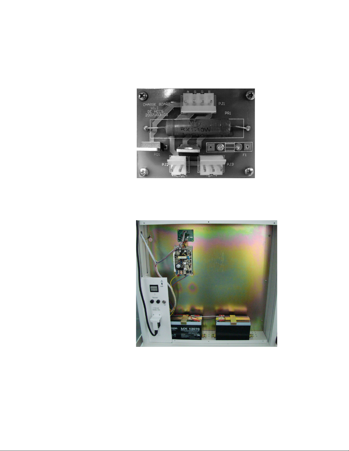
2.6.1 Power supply ZY9100 machines use a universal power supply for AC to DC
conversion. The conversion output supplies 27V DC. This is provided
to the charge board and the task light board.
When connected to AC, the charge board provides power to the
batteries and to the main board.
In case of AC supply loss, power is provided to the main board by the
batteries through the charge board. Battery charge level is then
shown on the display screen. The ventilator controls and alarms are
powered by the battery, but the task light is not.
2-14 M1170718
Page 35
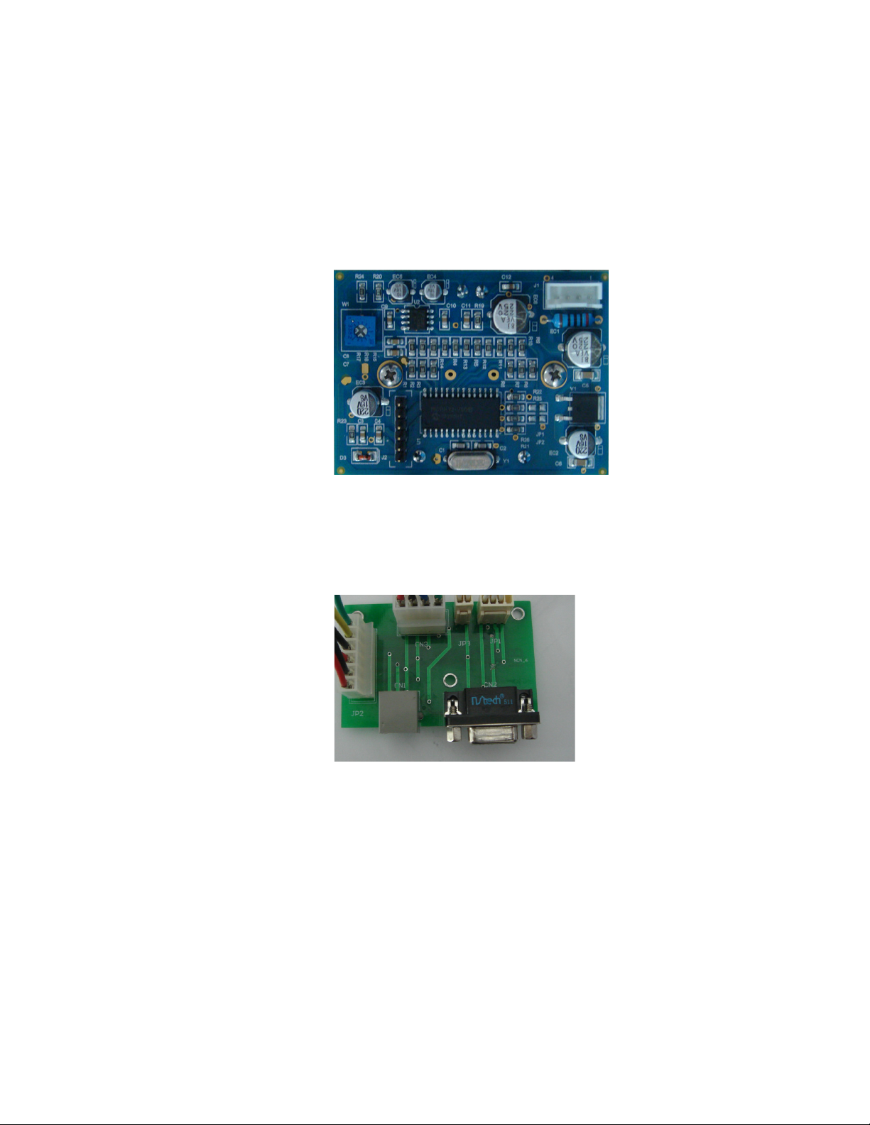
2 Theory of Operation
2.6.2 Alarm and signal switch
The alarm and data distribution functions are accomplished by the
following:
• Alarm board
• Interface board
Alarm board The alarm board uses an oscillating circuit to generate audio alarms
when they are received from the main board.
Interface board The interface board is used to distribute signals and provides an
RS-232 communications port for the user. Refer to Section 2.8 for
information on port protocol.
M1170718 2-15
Page 36
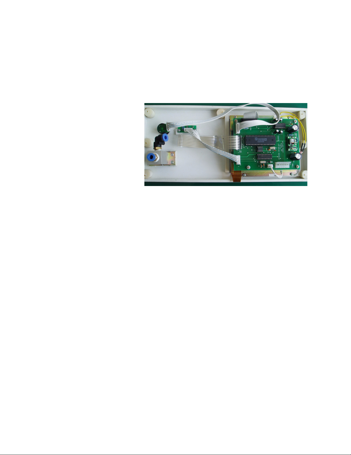
ZY9100
2.6.3 Display The display provides the user interface. It consists of the following:
• LCD display
• Display board
• Inverter board (mounted under the display board)
• Indicator board
• Driver board (mounted under the display board)
The display board is connected to the control knob (encoder) and the
main board.
The display is controlled by the driver board. The display board
transmits information to the driver board, and the indicators are
controlled by the display board.
JP2 of the display board is connected to JP1 of the main board, and
by using 89C58 it completes the transmission of signals with the main
board through the RS-232 serial port.
2-16 M1170718
Page 37
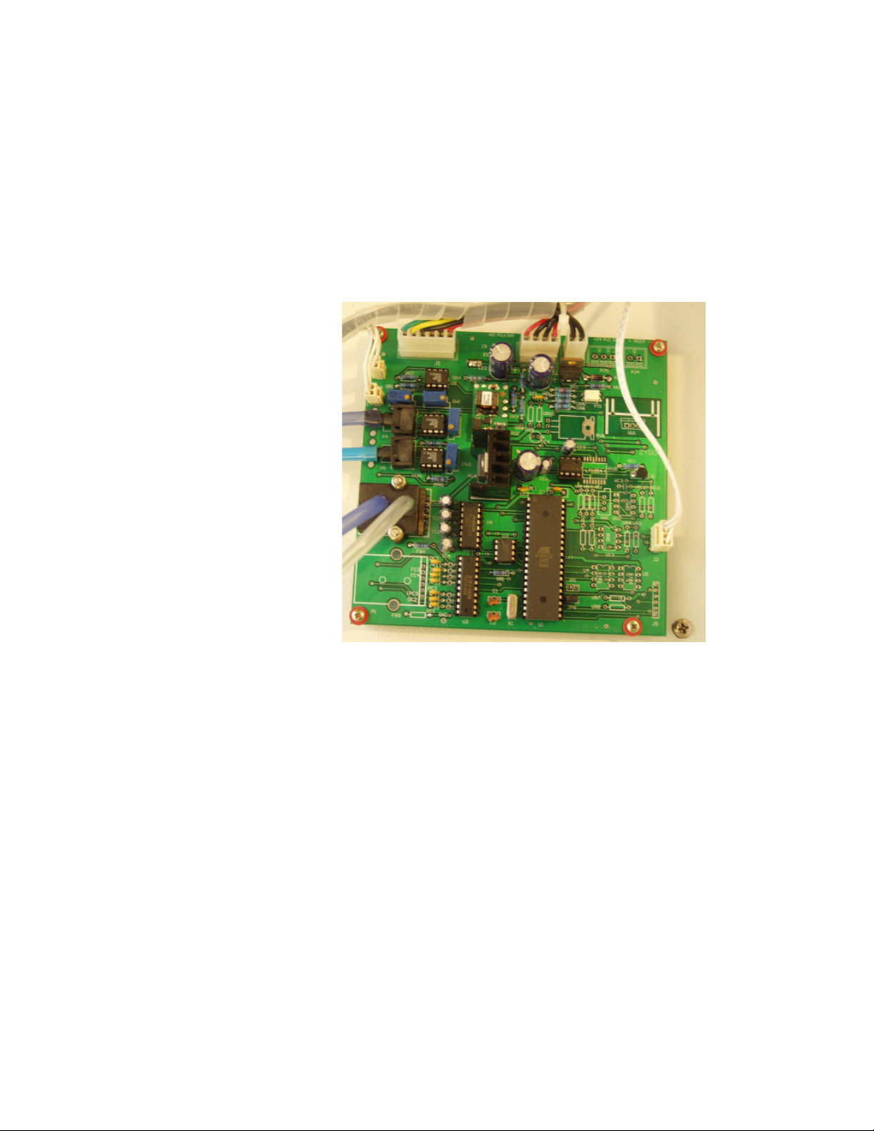
2 Theory of Operation
8
2.6.4 Control System control is performed by the main board.
The main board gathers and processes signals for flow, pressure,
and O
controls the solenoid valve through the D/A switch circuit. It transmits
signals to the display through the RS-232 serial port at 9600 BAUD.
The airway pressure and oxygen supply are fed to the main board to
monitor pressure. Connector interfaces with the display board
provides power to the main board. This board interfaces with the task
light.
% through the A/D circuit. Based on the ventilator settings, it
2
M1170718 2-17
Page 38
ZY9100
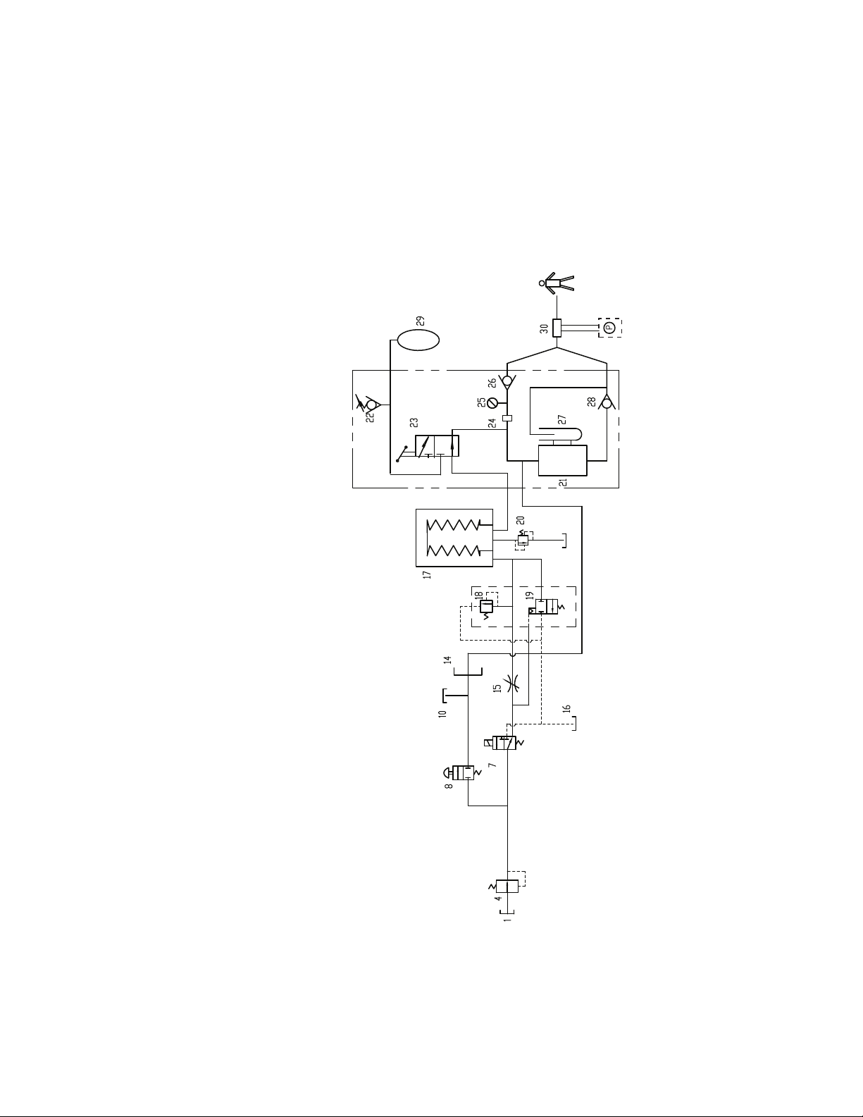
2.7 Pneumatic subsystems
The mechanical subsystems for the ventilator include:
• Pressure regulator valve (4)
• Solenoid valve (7) and V
• Safety pressure relief (18) and exhalation valve (19)
• Pop-off valve (20)
control valve (15)
T
Figure 2-4 • ZY9100 Ventilator mechanical subsystems
2-18 M1170718
Page 39
2 Theory of Operation
1
2
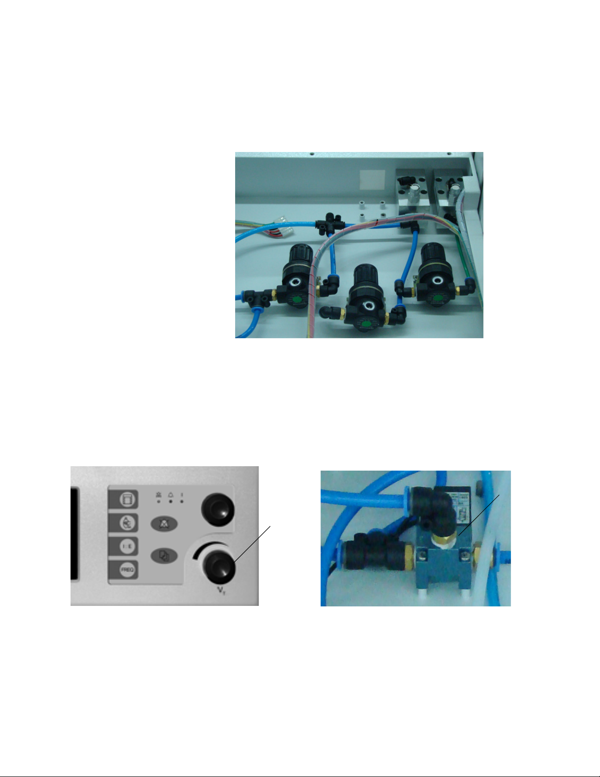
2.7.1 Pressure regulators
The ZY9100 contains up to three low-pressure regulators. One
regulator supplies oxygen to the flowmeter assembly. A second
regulator provides oxygen for the O
drive gas. If the machine includes nitrous oxide, the N
supplies gas to the flowmeter assembly.
flush valve and the ventilator
2
O regulator
2
2.7.2 Solenoid valve
and V
control valve
T
The VT control valve, located on the display module, is used to set the
amount of drive gas delivered to the bellows housing through the
exhalation/overpressure relief valve.
The solenoid valve is used to open and close the O
to the ventilator.
1. VT control valve
2. Solenoid valve
drive gas supply
2
M1170718 2-19
Page 40
ZY9100
pop-off valve
Flow
sensor
adapter
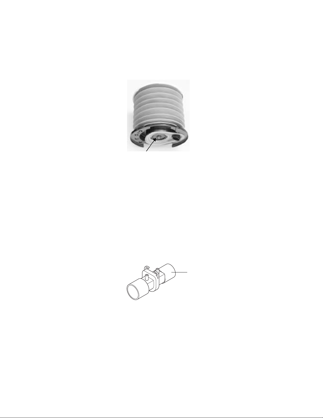
2.7.3 Pop-off valve The bellows assembly is the connection between the drive gas and
patient airway in the respiration system. The pop-off valve of the
bellows assembly controls the pressure in the respiration circuit and
discharges the excessive gas from the patient through the exhaust
gas outlet.
2.7.4 Flow sensor adapter
The pop-off valve limits the pressure inside the bellows to 2.5 cmH
above the drive gas pressure. This normally occurs when the bellows
reaches the top of the housing at the end of exhalation.
The flow sensor adapter is installed at the patient’s Y-piece
connector. The flow sensor adapter monitors the expired V
gas flows through the sensor adapter a pressure difference is
generated between the two sides of the sensor diaphragm. The
pressures are measured and interpreted on the main board in order
to calculate the V
adapter must be connected correctly in order for the volume data to
be properly measured and displayed. The tube nearest the patient
must be connected to the port marked “+” on the rear of the machine.
value. The tubes connected to the flow sensor
T
. When
T
O
2
2-20 M1170718
Page 41
2.8 RS-232 Communication protocol
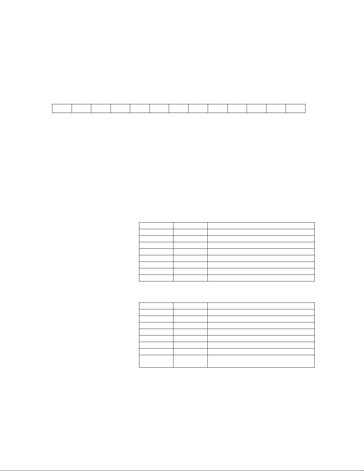
D0 D1 D2 D3 D4 D5 D6 D7 D8 D9 D10 D11 D12
Communication of the display and control data is done through a
serial port.
Set up of the serial port: 9600bps, 8 bit, 1 stop
Data set format: every set has 13 bytes
D0: The original sign of the set; fixed at 0AAH.
D1: Data set types:
• 03H refers to waveform, alarm data, and set parameters. this
set is transmitted once every 50 ms.
• 04H refers to measured data. The set is transmitted 25 ms
after the end of the respiration.
D11: Checkout value; D11 = (the sum of D1 to D10) or 0FH.
D12: The end sign of the set, fixed at 055H.
When D1 = 03H:
2 Theory of Operation
D2 Pawi Instantaneous airway pressure value (unit: hPa)
D3 ALARM2 Alarm byte 2
D4 FLOWi Instantaneous flow value (unit: L/min)
D5 VTi Instantaneous tidal volume value (unit: 10mL1)
D6 ALARM1 Alarm byte 1
D7 O2 Value of O2 concentration (unit: %)
D8 STATUS Status byte
D9 PNO Set parameter number
D10 PVALUE Set parameter value
When D1 = 04H:
D2 VT Tidal volume measured value (unit: 10 ml)
D3 MVH Minute ventilation volume value (unit: 10 ml/min)
D4 MVL Minute ventilation volume value (unit: 10 ml/min)
D5 PEAK Peak airway pressure measure value (unit: hPa)
D6 PMean Mean pressure measured vlaue (unit: hPa)
D7 PEEP PEEP measured value (unit: hPa)
D8 Pplat Platform pressure measured value (unit: hPa)
D9 CL Compliance measured value (unit: L/kPa)
D10 Freq Frequency actual measured value (unit: times/
min)
Note When M-904E, D4, D5, and D7 are not used.
When ZY9100, D5 is not used.
M1170718 2-21
Page 42

ZY9100
Definition of STATUS
ALARM1 Definition
BIT0 -- Standby
BIT1 -- Standby
BIT2 -- Standby
BIT3 -- Standby
BIT4 Trigger Flag Trigger status symbol. 0 no trigger; 1 trigger.
BIT5 PawSign Airway pressure symbol. 0 for positive; 1 for
negative.
BIT6 FlowSign Flow speed symbol. 0 for positive; 1 for negative.
BIT7 IE Flag Inhalation and exhalation status symbol. 0 for
inhalation; 1 for exhalation.
Note When M-904, BIT 4, BIT 5, and BIT 6 are not used.
BIT0 NOGAS Insufficient gas source alarm.
BIT1 AC Fail AC failure alarm.
BIT2 Battery Low Low battery alarm.
BIT3 Paw High High Paw alarm.
BIT4 Paw Low Low Paw alarm.
BIT5 VT High High tidal volume alarm.
BIT6 VT Low Low tidal volume alarm.
BIT7 O2 High High O2% alarm.
Note When M-904, BIT 5, BIT 6, and BIT 7 are not used.
ALARM2 Definition
Note When M-904, BIT0, BIT1, BIT2, and BIT3 are not used.
BIT0 O2 Low Low O2% alarm.
BIT1 MV High High minute ventilation value alarm.
BIT2 MV Low Low minute ventilation value alarm.
BIT3 No O2 Sensor No O2 sensor alarm.
BIT4 Sustained
Paw
BIT5 -- Standby
BIT6 -- Standby
BIT7 -- Standby
Continuous high Paw alarm.
2-22 M1170718
Page 43

PNO definition
2 Theory of Operation
Number Description
1 FREQ: Respiration Frequency default value (unit: times/min).
2 RATIO: Inspiration and exhalation ratio set value x 10. If it is 20, it means
that the inspiration/exhalation ratio is 1:2.0.
3 TRG: Triggering sensitivity set value (unit: -hPa).
4 VT: Tidal volume set value (unit: 10 ml). ZY9100 does not use.
5 CLT: Compliant compensation set value (unit: %). ZY9100 does not use.
6 SIGH: Sigh times set value (unit: times). ZY9100 does not use.
7 TIP: Platform time percentage set value (unit: %). ZY9100 does not use.
8 PEEP: PEEP set value (unit: -hPa). ZY9100 does not use.
9 PH: Paw alarm upper limit (unit: hPa).
10 PL: Paw alarm lower limit (unit: hPa).
11 VTH: Tidal volume alarm upper limit (unit: 10 ml).
12 VTL: Tidal volume alarm lower limit (unit: 10 ml).
13 MVH: Minute ventilation alarm upper limit (unit: L/min).
14 MVL: Minute ventilation alarm lower limit (unit: L/min).
15 O2H: O2% upper limit (unit: %).
16 O2L: O2% lower limit (unit: %).
17 PAWGAIN: Airway pressure gain (unit: -). System parameter.
18 PAWZERO: Airway pressure zero (unit: -). System parameter.
19 VTGAIN: Tidal volume gain (unit: -). System parameter.
20 VTZERO: O2 density zero (unit: -). System parameter.
21 O2GAIN: O2% gain (unit: -). System parameter.
22 O2ZERO: O2density zero (unit: -). System parameter.
23 PEEPZERO: PEEP zero (unit: -). System parameter.
24 PMAX: Pmax set value in PC mode (unit: -). ZY9100 does not use.
25 SETTING: Model set value (unit: -). 1 for ZY9100.
26 MUTE: Mute set value (unit: -). 0 for no mute; 1 for mute.
M1170718 2-23
Page 44

ZY9100
2-24 M1170718
Page 45

3 Checkout Procedure
In this section 3.1 Post-service checkout . . . . . . . . . . . . . . . . . . . . . . . . . . 3-3
3.2 Inspect the system . . . . . . . . . . . . . . . . . . . . . . . . . . . . . 3-4
3.3 Power failure test . . . . . . . . . . . . . . . . . . . . . . . . . . . . . . 3-5
3.4 Pipeline and cylinder tests . . . . . . . . . . . . . . . . . . . . . . . 3-6
3.5 Safety pressure relief valve test . . . . . . . . . . . . . . . . . . . 3-7
3.6 Flow control tests . . . . . . . . . . . . . . . . . . . . . . . . . . . . . . 3-8
3.7 O2 supply alarm test . . . . . . . . . . . . . . . . . . . . . . . . . . 3-10
3.8 Flush flow test . . . . . . . . . . . . . . . . . . . . . . . . . . . . . . . 3-11
3.9 Vaporizer back pressure test . . . . . . . . . . . . . . . . . . . . 3-12
3.10 Low-pressure leak test . . . . . . . . . . . . . . . . . . . . . . . . 3-13
3.11 Alarm tests . . . . . . . . . . . . . . . . . . . . . . . . . . . . . . . . . 3-16
3.12 Breathing system tests . . . . . . . . . . . . . . . . . . . . . . . 3-18
3.12.1 Check valves . . . . . . . . . . . . . . . . . . . . . . . . . . . 3-18
3.12.2 Ventilator bellows . . . . . . . . . . . . . . . . . . . . . . . 3-18
3.12.3 Bag circuit . . . . . . . . . . . . . . . . . . . . . . . . . . . . . 3-18
3.12.4 APL Valve . . . . . . . . . . . . . . . . . . . . . . . . . . . . . 3-18
3.13 Electrical safety tests . . . . . . . . . . . . . . . . . . . . . . . . . 3-20
M1170718 3-1
Page 46

ZY9100
WARNING After any repair or service of the anesthesia system,
complete all tests in this section.
Before performing the tests in this section:
• Complete all necessary calibrations and subassembly
tests. Refer to the individual procedures for a list of
necessary calibrations.
• Completely reassemble the system.
If a test failure occurs, make appropriate repairs and test
for correct operation.
3-2 M1170718
Page 47

3.1 Post-service checkout
After servicing the ZY9100 Anesthesia system run the Service menu
tests pertinent to the components replaced. Perform calibration on
the flow sensor, pressure sensitivity, and the flow valve.
Then, complete the checkout procedure for the entire machine in the
following sections.
3 Checkout Procedure
M1170718 3-3
Page 48

ZY9100
3.2 Inspect the system
CAUTION The upper shelf weight limit is 20 kg (45 lb).
WARNING Do not leave gas cylinder valves open if the pipeline
supply is in use. Cylinder supplies could be depleted,
leaving an insufficient reserve supply in case of pipeline
failure.
Before testing the system, make sure that:
• The equipment is not damaged.
• Components are correctly attached.
• The breathing circuit is correctly connected, not damaged.
• Pipeline gas supplies are connected.
• Cylinder valves are closed.
• Models with cylinder supplies have a cylinder wrench attached to
• Models with cylinder supplies have a reserve supply of O
• The power cord is connected to a wall outlet.
• The casters are not loose and the brakes are set and prevent
the system.
connected to the machine during system checkout.
movement.
2
3-4 M1170718
Page 49

3.3 Power failure test
3 Checkout Procedure
1. Connect the power cord to the mains outlet. Set the power switch
to On. The power indicator on the top right corner of the display
comes on when AC power or the battery is connected.
• If the power indicator is on and the “On Battery, power Ok?”
message displays:
— Verify AC power to the machine
— Check the fuses in the AC inlet assembly
• If the power indicator is not lit:
— Check the battery for charge
— Check the battery connection from the charge board to
the system
2. Unplug the power cord with the system turned on.
3. Make sure that the power failure alarm comes on.
4. Make sure the following message is on the ventilator display:
‘On Battery, power OK?’
5. Connect the power cable again.
6. Make sure the alarm cancels.
M1170718 3-5
Page 50

ZY9100
3.4 Pipeline and cylinder tests
CAUTION To prevent damage:
• Open the cylinder valves slowly.
• Do not force the flow controls.
If your system does not use cylinder supplies, do not do steps 2
and 3.
1. Disconnect the pipeline supplies and close all cylinder valves. If
the pipeline and the cylinder pressure gauges are not at zero,
bleed all gasses from the system.
• Connect an O
• Set the power switch to On.
• Set the flow controls to mid range.
• Make sure that all gauges but O
• Disconnect the O
• Make sure that the O
decreases, alarms for low O
Note: Other ventilator alarms will activate.
• Reconnect the O
gauge and the alarm should deactivate.
• Turn the power switch to Off.
2. Make sure that the cylinders are full:
• Open each cylinder valve, one at a time.
• Make sure that each cylinder has sufficient pressure. If not,
close the applicable cylinder valve and install a full cylinder.
3. Test one cylinder at a time for high pressure leaks:
• Turn the flow control knobs fully clockwise to stop gas flow.
• Open the cylinder.
• Record the cylinder pressure.
• Close the cylinder valve.
• Record the cylinder pressure after one minute. If the pressure
has decreased more than 5000 kPa (725 psi), leak must be
repaired.
Install a new cylinder gasket and do this step again.
• Repeat step 3 for each cylinder. For N
pressure has decreased more than 690 kPa (100 psi), leak
must be repaired.
Install a new cylinder gasket and do this step again.
supply.
2
are at zero.
2
supply.
2
gauge goes to zero. As pressure
2
supply pressure should occur.
2
supply. O2 pressure should show on the
2
O cylinder, if the
2
4. Connect the pipeline supplies one at a time and ensure that the
corresponding gauge indicates pipeline pressure.
3-6 M1170718
Page 51

3.5 Safety pressure relief valve test
This test uses the ventilator drive gas to pressurize the breathing
circuit. The airway pressure gauge is used to verify the opening
pressure of the relief valve.
1. Remove the bellows and reinstall the bellows housing. The
bellows mounting rim, latch, and relief valve must remain in
place.
2. Connect the patient circuit to the breathing system.
3. Remove the flow sensor from the patient circuit.
4. Set the Manual/Mechanical ventilation to mechanical.
5. Set the power switch to On.
6. Push the control knob on the display to exit Standby mode.
7. Push the bellows key to start mechanical ventilation.
8. Set
9. Use a test plug or your thumb to block the patient Y-connection.
FREQ to 4 and I:E to 1.0.
3 Checkout Procedure
10. Adjust
opening pressure of the relief valve.
11. Verify that the maximum reading on the airway pressure gauge is
between 54 and 60 cmH
V
until the pressure during inspiration exceeds the
T
O.
2
M1170718 3-7
Page 52

ZY9100
3.6 Flow control tests
WARNING Nitrous oxide (N2O) flows through the system during this
Note If the system does not include N
Note Allow the O
test. Use a safe and approved procedure to collect and
remove it.
1. Set up the gas scavenging system.
• Attach a patient circuit and plug the patient port.
• Attach a bag to the bag port (or plug the bag port).
• Set the Manual/Mechanical ventilation switch to manual.
• Adjust the APL valve to minimum.
2. Connect the pipeline supplies or slowly open the cylinder valves.
3. Turn all flow controls fully clockwise (zero flow).
4. Set the power switch to On, push the control knob one time to
enter Normal mode, and push the bag key on the display.
5. Adjust O
6. Confirm that the O
in pure O
7. Set the flow controls to mid range of each flowtube and make
sure that the flowtube floats rotate and move smoothly.
8. Check the proportioning system concentration (increasing N
flow). Observe the following precautions:
• Start with all valves at the minimum setting.
• Adjust only the N
• Increase the N
may take up to 90 seconds to stabilize.
• If you overshoot a setting, turn the O
flow to 0.5 L/min.
2
sensor measures 21% in room air and 100%
. If not, calibrate the O2 sensor.
2
make sure the O
monitor to stabilize. At the lower flows, the O2 monitor
2
until the N
2
O, skip steps 8 and 9.
2
O flow control.
2
O flow as specified in the following table and
2
concentration is in range.
2
flow control clockwise
O flow decreases to the previous setting before
2
2
continuing the test.
O
2
Set the N2O flow (L/min) Measured O
0.15 21% minimum
0.5 21% minimum
0.8 21% to 30%
1.0 21% to 30%
2.0 21% to 30%
6.0 21% to 30%
9.0 21% to 30%
9. Check the proportioning system concentration (decreasing O
2
2
flow). Observe the following precautions:
• Start with the N
• Adjust only the O
• Decrease the O
O valve at the maximum setting.
2
flow control.
2
flow as specified in the table and make sure
2
3-8 M1170718
Page 53

the O
Note Allow the O
may take up to 90 seconds to stabilize.
• If you overshoot a setting, turn the N
counterclockwise until the O
setting before continuing the test.
3 Checkout Procedure
concentration is in the allowed range.
2
monitor to stabilize. At the lower flows, the O2 monitor
2
O flow control
2
flow increases to the previous
2
Set the O2 flow (L/min) Measured O
3.0 21% to 30%
2.0 21% to 30%
1.0 21% to 30%
0.3 21% to 30%
2
• If both tests meet the criteria, calibration is correct (go to the
next step). If either test fails to meet the criteria, replace the
flowtube module.
Note Adjusting the regulator pressure is not recommended. It has little
effect on proportioning.
10. Set the power switch to Off.
11. Turn all of the flow controls fully clockwise (closed).
M1170718 3-9
Page 54

ZY9100
3.7 O2 supply alarm test
1. Set all flow controls to 3 L/min.
2. Stop the O
supply. (Disconnect the pipeline supply or close the
2
cylinder valve.)
3. Make sure that:
• The Low O
•The N
alarm occurs.
2
O (if equipped) and O2 flows stop. The O2 flow stops
2
last.
4. Turn all of the flow controls fully clockwise (closed).
5. Reconnect the pipeline supplies.
3-10 M1170718
Page 55

3.8 Flush flow test
3 Checkout Procedure
1. Set the Manual/Mechanical ventilation switch to mechanical.
2. Attach a patient circuit and plug the patient port.
3. Make sure that the bellows is completely collapsed.
4. Measure the amount of time it takes to fill the bellows when the
O
flush button is fully and continuously depressed.
2
5. Repeat the above measurement two more times (deflate bellows
by removing the plug from the patient port).
6. The bellows should fill in approximately 2.0 seconds.
7. Possible Cause of Failure:
• Large leak (if long filling time).
• The setting of the pressure regulator is incorrect.
• The pressure regulator is incorrectly connected.
M1170718 3-11
Page 56

ZY9100
3.9 Vaporizer back pressure test
WARNING Anesthetic agent vapor comes out of the common gas
outlet during this test. Use a safe, approved procedure to
remove and collect the agent.
1. Set up the gas scavenging system.
• Attach a patient circuit and plug the patient port.
• Attach a bag to the bag port (or plug the bag port).
• Adjust the APL valve to minimum.
2. Set the Manual/Mechanical ventilation switch to manual.
3. Set the power switch to On and push the bag key on the display.
4. Set the O
5. Make sure that the O
freely.
6. Adjust the vaporizer concentration for each step from 0 to 1%.
The O
range. If the O
• Install a different vaporizer and try this step again.
•If the O
•If the O
7. Possible Cause of Failure:
• Vaporizer manifold port valve.
8. Complete steps 4 through 6 for each vaporizer and vaporizer
position.
9. Set the power switch to Off.
flow to 6 L/min.
2
flow must not decrease more than 1 L/min through the full
2
flow decreases less than 1 L/min with a different
2
vaporizer, the malfunction is in the first vaporizer.
flow also decreases more than 1 L/min with a
2
different vaporizer, the malfunction is probably in the ZY9100
system.
flow stays constant and the float moves
2
flow decreases more than 1 L/min:
2
10. Turn all of the flow controls fully clockwise (closed).
3-12 M1170718
Page 57

3.10 Low-pressure leak test
Note Perform either the “Negative low-pressure leak test” or the “ISO or
BSI standard low-pressure leak test.” It is not necessary to perform
both tests.
WARNING Do not use a system with a low-pressure leak. Anesthetic
gas will leak into the atmosphere, before reaching the
breathing circuit.
3 Checkout Procedure
Negative low-pressure
leak test
1. Test the leak test device:
• Put your hand on the inlet of the leak test device. Push hard
for a good seal.
• Squeeze the bulb to remove all air from the bulb.
• If the bulb completely inflates in less than 60 seconds,
replace the leak test device.
2. Turn off all vaporizers.
3. Test the anesthesia machine for low-pressure leaks:
• Turn all flow controls fully clockwise (closed). Do not over
tighten.
• Connect the test device to the common gas outlet.
• Compress and release the bulb until it is empty.
• The vacuum causes the floats to move. This is usual. If the
bulb completely inflates in 30 seconds or less, there is a leak
in the low-pressure circuit.
4. Test each vaporizer for low-pressure leaks:
• Set the vaporizer to 1%.
• Repeat step 3.
• Set the vaporizer to Off.
• Test the remaining vaporizers.
5. Disconnect the test device.
WARNING Agent mixtures from the low-pressure leak test stay in the
system. Always flush the system with O2 after the lowpressure leak test (1 L/min for one minute).
Turn off all vaporizers at the end of the low-pressure leak
test.
6. Flush the system with O2:
• Set the O
• Continue the O
• Turn the O
M1170718 3-13
flow to 1 L/min.
2
flow for one minute.
2
flow control fully clockwise (closed).
2
Page 58
ZY9100
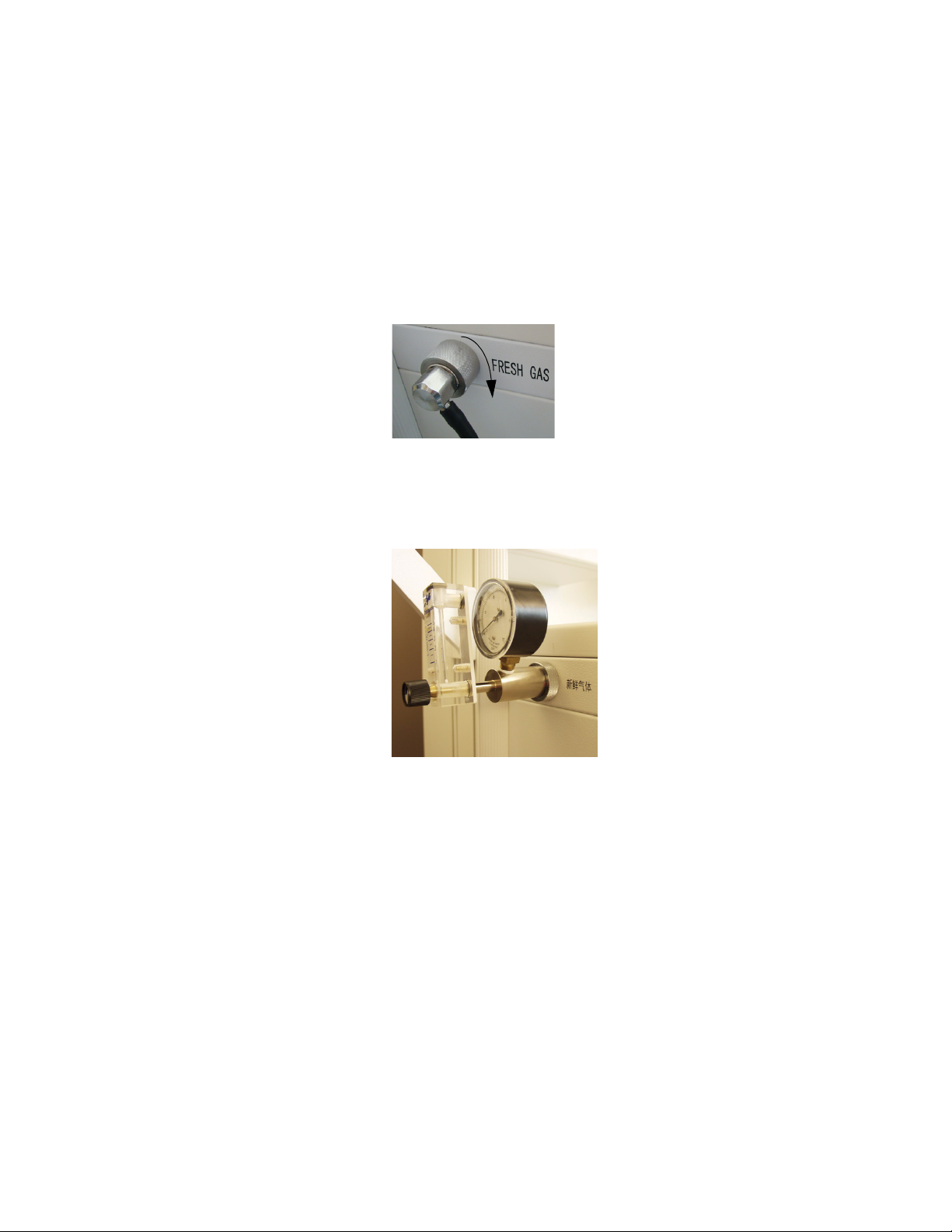
ISO or BSI standard low-
pressure leak test
CAUTION Do the positive pressure leak test at the common gas
outlet only.
1. Turn all flow controls fully clockwise (closed).
2. Remove the cap from the common gas outlet by turning the
knurled ring clockwise and then pulling the cap off.
3. Connect the test device to the common gas outlet.
• Test device ref:
1001-8976-000 (4 kPa)
1001-8975-000 (25 kPa)
4. Keep the flowmeter of the test device vertical for accurate results.
5. Fully open the needle valve on the test device
(counterclockwise).
CAUTION If the needle valve is not fully open, this test can damage
the pressure gauge on the test device.
6. Open the O2 flow control and set a total flow of 0.4 L/min through
the flowmeter on the test device.
7. Make sure that the pressure gauge on the test device reads zero
and that all other flow controls are fully closed.
8. Close the needle valve on the test device until the test gauge
reads:
ISO 5358 3 kPa
BSI 4272.3 20 kPa
3-14 M1170718
Page 59

3 Checkout Procedure
9. If the flow through the test device is less than:
0.35 L/min (ISO) or
0.3 L/min (BSI)
there is a low pressure leak in the anesthesia machine.
10. Fully open the needle valve on the test device to decrease the
back pressure.
11. Test each vaporizer for low-pressure leaks:
• Set the vaporizer to 1%.
• Repeat steps 5 through 8.
• Turn the vaporizer Off.
• Test the remaining vaporizers.
12. Remove the test tool.
WARNING Agent mixtures from the low-pressure leak test stay in the
system. Always flush the system with O2 after the lowpressure leak test (1 L/min for one minute).
Turn Off all vaporizers at the end of the low-pressure leak
test.
13. Flush the system with O2:
• Set the O
• Continue the O
• Turn the O
flow to 1 L/min.
2
flow for one minute.
2
flow control fully clockwise (closed).
2
M1170718 3-15
Page 60

ZY9100
3.11 Alarm tests
1. Connect a test lung to the patient connection.
2. Set the power switch to On.
3. Set the Manual/Mechanical ventilation switch to mechanical and
push the bellows key on the display.
4. Test the High O
and Low O2 alarms:
2
• Go to the Warning menu.
• Remove the O
• Make sure the sensor measures approximately 21% O
sensor from the circuit.
2
in
2
room air.
• Set the O
L alarm limit to 50%. Make sure a Low O2 alarm
2
occurs.
• Set the O
L alarm limit to 20% and make sure that the alarm
2
cancels.
• Put the O
• Push the O
• Set the O
• Set the O
• Make sure the High O
• Set the O
sensor back in the circuit.
2
flush button to fill the breathing system.
2
H alarm limit to 50%.
2
flow control to 2 L/min.
2
alarm comes On.
2
H alarm limit back to 100% and make sure the
2
alarm cancels.
• After 2 minutes in pure O
, the O
2
display reads
2
approximately 98%.
• Turn the O
5. Test the Low V
flow control fully clockwise (closed).
2
alarm:
E
• Go to the Warning menu.
• Set the V
• Adjust ventilator settings for V
• Make sure that a Low V
L alarm limit to 6.0 L/min.
E
L below 6.0.
E
alarm occurs.
E
• Go to the Warning menu.
• Set the V
L alarm limit to 0.0.
E
6. Test the high airway pressure alarm:
• Set PawH to less than the peak airway pressure.
• Make sure that the high airway pressure alarm occurs.
•Set PawH
to 40.
7. Test the sustained airway pressure alarm:
• Set the controls:
APL valve to fully closed.
Manual/Mechanical ventilation switch to manual and push the
bag key on the display.
• Mechanical ventilation stops.
• Close the bag port connector with a test plug.
• Close the patient connection using the test plug and push the
O
flush button.
2
• Make sure that the sustained pressure alarm occurs after
3-16 M1170718
Page 61

approximately 15 seconds at the sustained pressure limit
(6-30 cmH
O varies with pressure limit).
2
8. Set the power switch to Off.
3 Checkout Procedure
M1170718 3-17
Page 62

ZY9100
3.12 Breathing system tests
WARNING Objects in the breathing system can stop gas flow to the
patient. This can cause injury or death. Do not use a test
plug that is small enough to fall into the breathing system.
3.12.1 Check valves 1. Make sure that the check valves on the breathing circuit module
work correctly:
• The Inspiratory check valve rises during inspiration and falls
at the start of exhalation.
• The Expiratory check valve rises during exhalation and falls
at the start of inspiration.
3.12.2 Ventilator bellows
2. Ventilator bellows test:
• Set the power switch to Off.
• Set the Manual/Mechanical ventilation switch to mechanical.
• Turn all flow controls fully clockwise (closed).
• Use the test plug or your hand to close the breathing circuit at
the patient connection.
• Push the O
• The pressure must not increase to more than 15 cmH
the pressure gauge.
• If the bellows falls more than 100 mL/min (top of indicator), it
has a leak.
flush button to fill the bellows.
2
3.12.3 Bag circuit 3. Test the bag or manual circuit for leaks:
• Set the Manual/Mechanical ventilation switch to manual.
• Plug the bag port (use your hand or the approved test plug).
• Close the APL valve.
• Set the O
• Close the patient connection (using a hand or the approved
test plug) and pressurize the bag circuit with the O
button to approximately 30 cmH
• Release the O
decrease. A pressure decrease large enough to see on the
gauge indicates an unacceptable leak.
flow to 0.25 L/min.
2
O.
2
flush button. The pressure must not
2
2
flush
2
O on
3.12.4 APL Valve 4. Test the APL valve:
• Fully close the APL valve.
• Set the total fresh gas flow to approximately 3 L/min and
make sure that the value on the inspiratory pressure gauge
does not exceed 85 cmH
normal.
• Fully open the APL valve.
•Set O
• Make sure that the value on the inspiratory pressure gauge is
3-18 M1170718
flow to 3 L/min. Turn any other gases off.
2
O. Some pressure fluctuation is
2
Page 63

3 Checkout Procedure
less than approximately 5 cmH
• Push the O
flush button. Make sure that the value on the
2
inspiratory pressure gauge stays less than 10 cmH
• Set the O
flow to minimum and make sure that the value on
2
O.
2
O.
2
the inspiratory pressure gauge does not decrease below
0 cmH
O.
2
5. Remove your hand or the test plug from the patient connection.
6. Turn all flow controls fully clockwise (closed).
WARNING Make sure that there are no test plugs or other objects
caught in the breathing system.
M1170718 3-19
Page 64

ZY9100
3.13 Electrical safety tests
Make sure the system is completely assembled and all accessory
devices are connected to electrical outlets.
1. Connect an approved test device (e.g. UL, CSA, or AAMI) and
verify that the leakage current is less than 0.5 mA with the power
on.
2. Make sure that the resistance to ground is less than 0.2 Ω
between an exposed metal surface and the ground pin on the
power cord.
3-20 M1170718
Page 65

4 Service Tests and Calibration
In this section This section covers calibration procedures for components of the
ZY9100 anesthesia machine.
4.1 Cylinder regulators . . . . . . . . . . . . . . . . . . . . . . . . . . . . . 4-2
4.1.1 Test setup . . . . . . . . . . . . . . . . . . . . . . . . . . . . . . . 4-2
4.1.2 Testing cylinder regulators . . . . . . . . . . . . . . . . . . 4-3
4.1.3 Adjusting cylinder regulators . . . . . . . . . . . . . . . . . 4-6
4.2 Low-pressure regulators . . . . . . . . . . . . . . . . . . . . . . . . 4-7
4.2.1 Testing and adjusting low- pressure regulators . . 4-7
4.3 Hypoxic guard calibration . . . . . . . . . . . . . . . . . . . . . . . . 4-8
4.4 Airway pressure gauge . . . . . . . . . . . . . . . . . . . . . . . . . 4-9
4.4.1 Zero the pressure gauge . . . . . . . . . . . . . . . . . . . . 4-9
4.4.2 Checking the pressure gauge accuracy . . . . . . . 4-10
4.5 Parameter calibration . . . . . . . . . . . . . . . . . . . . . . . . . . 4-11
4.5.1 System calibration . . . . . . . . . . . . . . . . . . . . . . . . 4-11
4.5.2 Paw calibration . . . . . . . . . . . . . . . . . . . . . . . . . . 4-12
4.5.3 VT calibration . . . . . . . . . . . . . . . . . . . . . . . . . . . 4-13
4.5.4 Calibration of inspired O2% . . . . . . . . . . . . . . . . 4-14
4.5.4 Calibration of inspired O2% . . . . . . . . . . . . . . . . 4-14
M1170718 4-1
Page 66
ZY9100
Remove plug
WARNING After adjustments and calibration are completed, always
perform the checkout procedure. Refer to Section 3 of this
manual.
4.1 Cylinder regulators
WARNING When testing/adjusting N2O regulators, nitrous oxide
flows through the system. Use a safe and approved
procedure to collect and remove it.
4.1.1 Test setup
WARNING Wear safety glasses while a test device is connected to
the test port.
CAUTION Be careful not to plug the output of the cylinder regulator
without having a pressure relief valve in the output circuit.
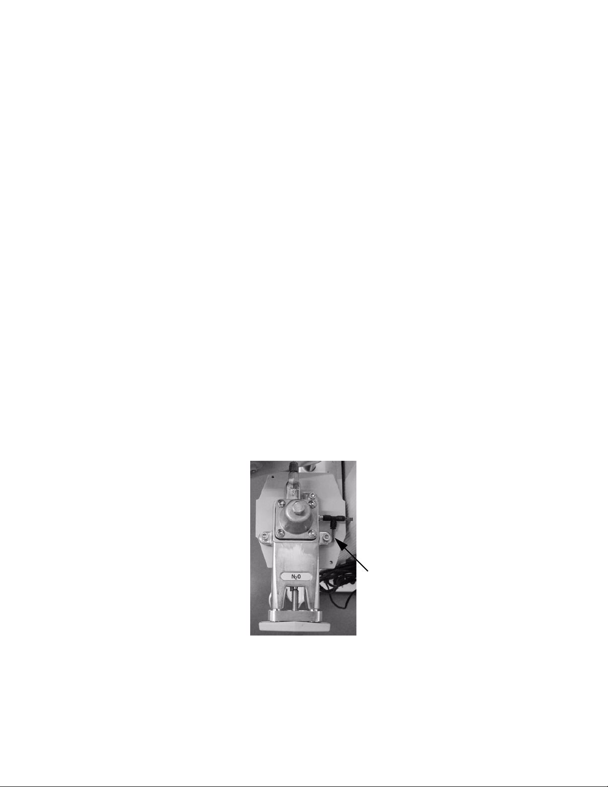
1. Set the power switch to Off.
2. Disconnect all pipeline supplies.
3. Remove the cylinder regulator cover.
4. Install a full cylinder in the cylinder supply to be tested. It is
essential that the cylinder be within 10% of its full pressure.
5. Remove the plug from the test port and connect a test device
capable of measuring 689 kPa (100 psi).
4-2 M1170718
Page 67
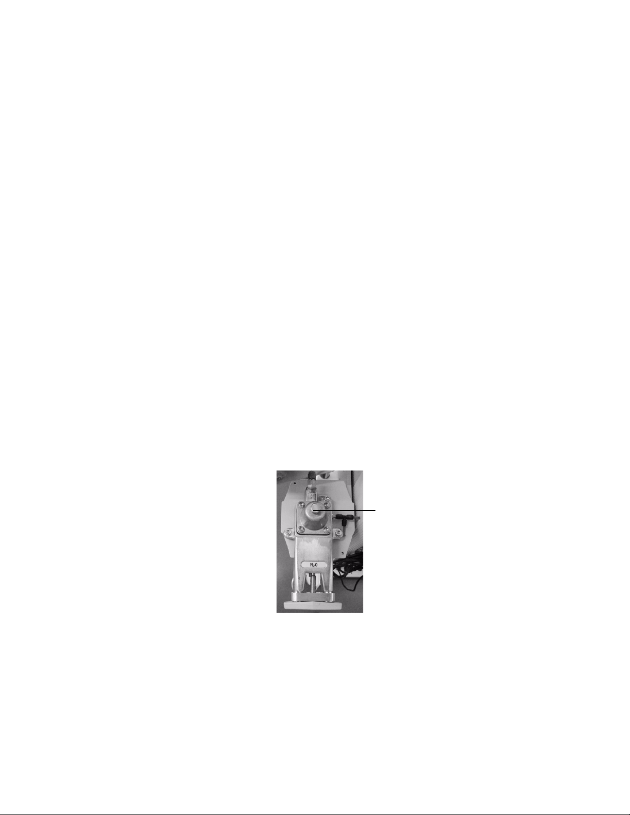
4 Service Tests and Calibration
Adjust
clockwise
to increase
4.1.2 Testing
cylinder regulators
Test A For cylinder regulators that supply drive gas to the ventilator
There are two variations of the test procedure for the cylinder
regulators:
•Test A — For cylinder regulators that supply drive gas to the
ventilator (oxygen).
•Test B — For all other gases.
(O
):
2
Under low flow conditions, the output pressure of a properly adjusted/
functioning regulator should fall within specifications listed in step 1.
Under high flow conditions, the output pressure should not drop
below the specifications in step 2.
1. Low Flow Test:
• Slowly open the cylinder valve.
• Set the common gas flow for O
• Close the cylinder valve and allow the pressure to decay to
2068 kPa (300 psi) as indicated on the cylinder gauge (upper
limit of the red band). The flow may be temporarily increased
to facilitate the decay.
• When the cylinder pressure reaches 2068 kPa
(300 psi) close the O
• Within one minute, the test device must stabilize between
310 to 341 kPa (45.0 to 49.5 psi).
If the test device pressure does not stabilize within one
minute, replace the cylinder supply.
If the test device stabilizes within one minute, but the
readings are not within specifications, readjust the regulator
(Section 4.1.3).
flow control valve.
2
to 0.1 L/min.
2
2. High Flow Test:
• Slowly open the cylinder valve.
• Remove the bellows housing.
• Set the power switch to On. Push the control knob one time
M1170718 4-3
to enter Normal mode.
•Set
•Set
• Turn inspiratory flow (tidal volume) adjustment fully
I:E to 0.5.
FREQ to 4 BPM.
Page 68

ZY9100
counterclockwise (maximum).
• Observe the test device for at least 1 minute (4 inspirations).
• During each inspiration the minimum test device reading
observed must be greater than: 207 kPa (30 psi).
• If the test device reading under “high flow” conditions is less
than specified, readjust the regulator per the procedure in
Section 4.1.3; however, set the regulated pressure higher by
the difference noted in this step plus 7 kPa (1 psi). This
adjusts the “low flow” regulated output to the high side of the
specification so that the “high flow” regulated pressure can
fall within the specification.
If the regulator subsequently fails the “low flow” specification
(step 2) because the reading is too high, replace the cylinder
supply.
3. Set the power switch to Off.
4. Close the cylinder valve.
5. Bleed the system of all pressure (Section 8.1).
6. Disconnect the test device and plug the test port (pull on the plug
to make sure it is locked in the fitting).
7. Replace the bellows housing.
8. After the last regulator has been tested, perform the checkout
procedure (Section 3) and replace the cylinder cover.
Test B For all other gases:
Under low flow conditions, the output pressure of a properly adjusted
and functioning regulator should fall within specifications listed in
step 2. Under high flow conditions, the output pressure should not
drop below the specifications in step 3.
1. If the cylinder supply being tested is N
to pressurize the balance regulator and allow N
2. Low Flow Test:
• Slowly open the cylinder valve for the regulator being tested.
• Set the flow of the gas being tested to
0.05 L/min.
• Close the cylinder valve and allow the pressure to decay to
2068 kPa (300 psi) as indicated on the cylinder gauge (upper
limit of the red band). The flow may be temporarily increased
to facilitate the decay.
• When the cylinder pressure reaches 2068 kPa
(300 psi), close the flow control valve.
• Within one minute, the test device must stabilize between
310–341 kPa (45.0–49.5 psi).
If the test device pressure does not stabilize within one
minute, replace the cylinder supply.
If the test device stabilizes within one minute, but the
readings are not within specifications, readjust the regulator
(Section 4.1.3).
3. High Flow Test:
O, connect a source of O2
2
O to flow.
2
4-4 M1170718
Page 69

4 Service Tests and Calibration
• Slowly open the cylinder valve.
• Set the flow control valve to the maximum indicated flow on
the flow tube.
• The test device reading must be greater than 221 kPa
(32 psi).
If the test device reading under “high flow” conditions is less
than specified, readjust the regulator per the procedure in
Section 4.1.3; however, set the regulated pressure higher by
the difference noted in this step plus 7 kPa (1 psi). This
adjusts the “low flow” regulated output to the high side of the
specification so that the “high flow” regulated pressure can
fall within the specification.
If the regulator subsequently fails the “low flow” specification
(step 3) because the reading is too high, replace the cylinder
supply.
4. Close the cylinder valve.
5. Bleed the system of all pressure (Section 8.1).
6. Disconnect the test device and plug the test port (pull on the plug
to make sure it is locked in the fitting).
7. After the last regulator has been tested, perform the checkout
procedure (Section 3).
M1170718 4-5
Page 70

ZY9100
4.1.3 Adjusting
cylinder regulators
Important Cylinder supplies in a ZY9100 machine must have all high-pressure
Important Install a full cylinder in the cylinder supply to be adjusted. It is
regulators set to the same pressure range. If a regulator is replaced,
the replacement regulator must be set (as required) to the same
specification as the one removed.
essential that the cylinder be within 10% of its full pressure.
If the cylinder supply being adjusted is N
and set the O
low-pressure regulator).
Remove the covers to gain access to the cylinder regulators.
Do not attempt to adjust without flow.
1. Slowly open the cylinder valve.
2. Set and maintain the common gas flow of the gas being tested to
0.01 L/min (or minimum flow for O
3. Close the cylinder valve and allow the pressure to decay to
2068 kPa (300 psi) as indicated on the cylinder gauge (upper limit
of the red band). The flow may be temporarily increased to
facilitate the decay.
4. When the cylinder gauge reaches the upper limit of the red band,
adjust the regulator output pressure to:
327 to 341 kPa (47.5 to 49.5 psi).
flow control to the minimum stop (pilot pressure for
2
O, connect a source of O2
2
).
2
Note It may be necessary to open the cylinder valve and repeat steps 3
and 4 a number of times to achieve the above setting.
5. Test the regulator settings per the appropriate test in Section
4.1.2.
4-6 M1170718
Page 71
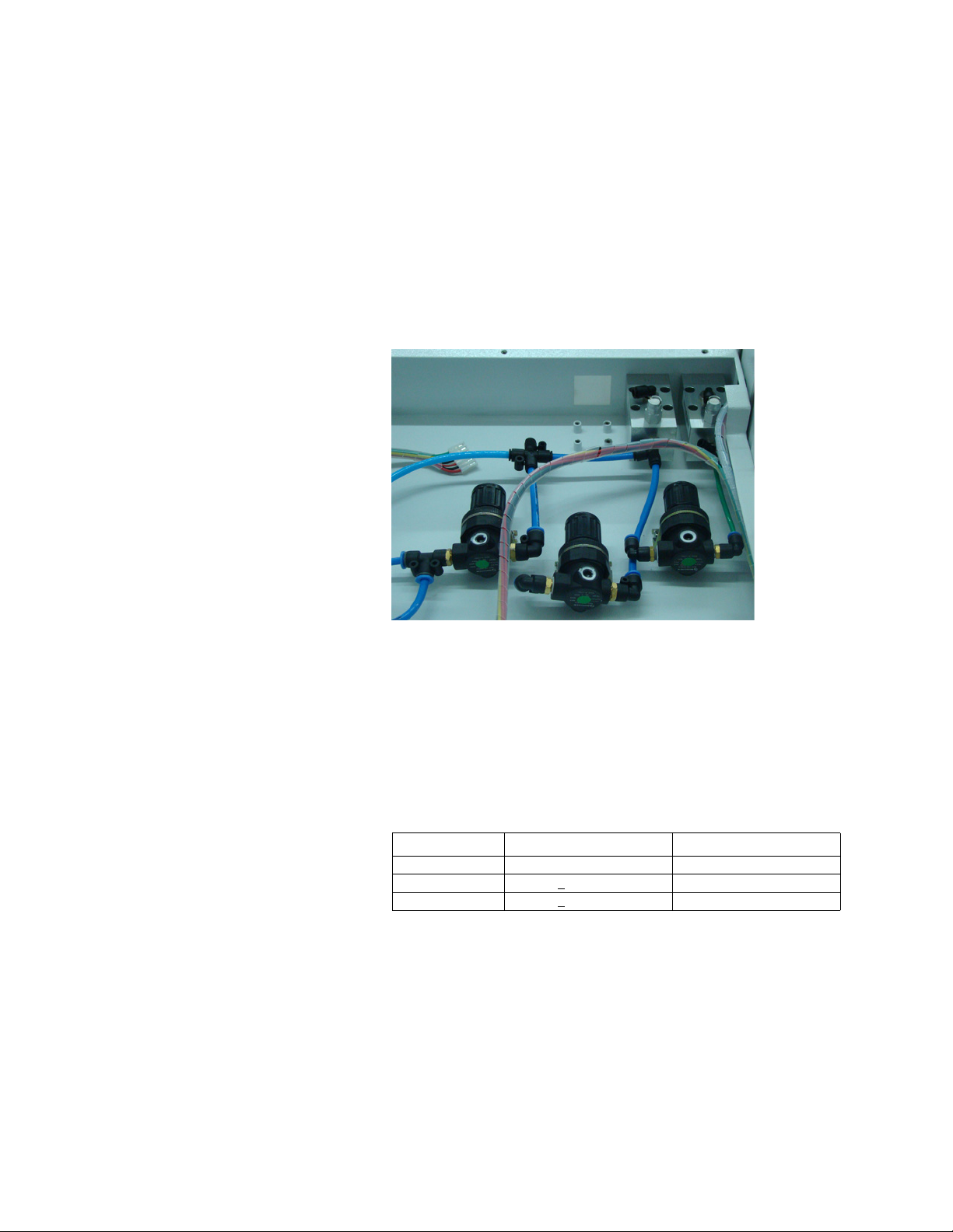
4.2 Low-pressure regulators
WARNING When testing N2O regulators, nitrous oxide flows through
the system. Use a safe and approved procedure to collect
and remove it.
4 Service Tests and Calibration
4.2.1 Testing and
adjusting low-
pressure regulators
1. Bleed the system of all pressure (Section 8.1).
2. Connect a pressure meter to the test plug that is attached to the
regulator output on the regulator being tested.
3. Set the flow through the regulator being tested as detailed in the
chart.
4. Verify that the output of the tested regulator is within the range
listed in the chart.
5. Adjust as necessary.
6. After all regulators have been tested, perform the Post-service
checkout (Section 3).
Regulator Output Flow Regulated gas
O 260 kPa + 20 kPa 2 L/min
N
2
O
2
Flush 200 kPa + 20 kPa Flush flow
O
2
M1170718 4-7
220 kPa + 20 kPa 2 L/min
Page 72

ZY9100
4.3 Hypoxic guard calibration
The hypoxic guard is an internal system that is not serviceable. If the
hypoxic guard is out of calibration or is misfunctioning, replace the
entire flow control assembly.
4-8 M1170718
Page 73
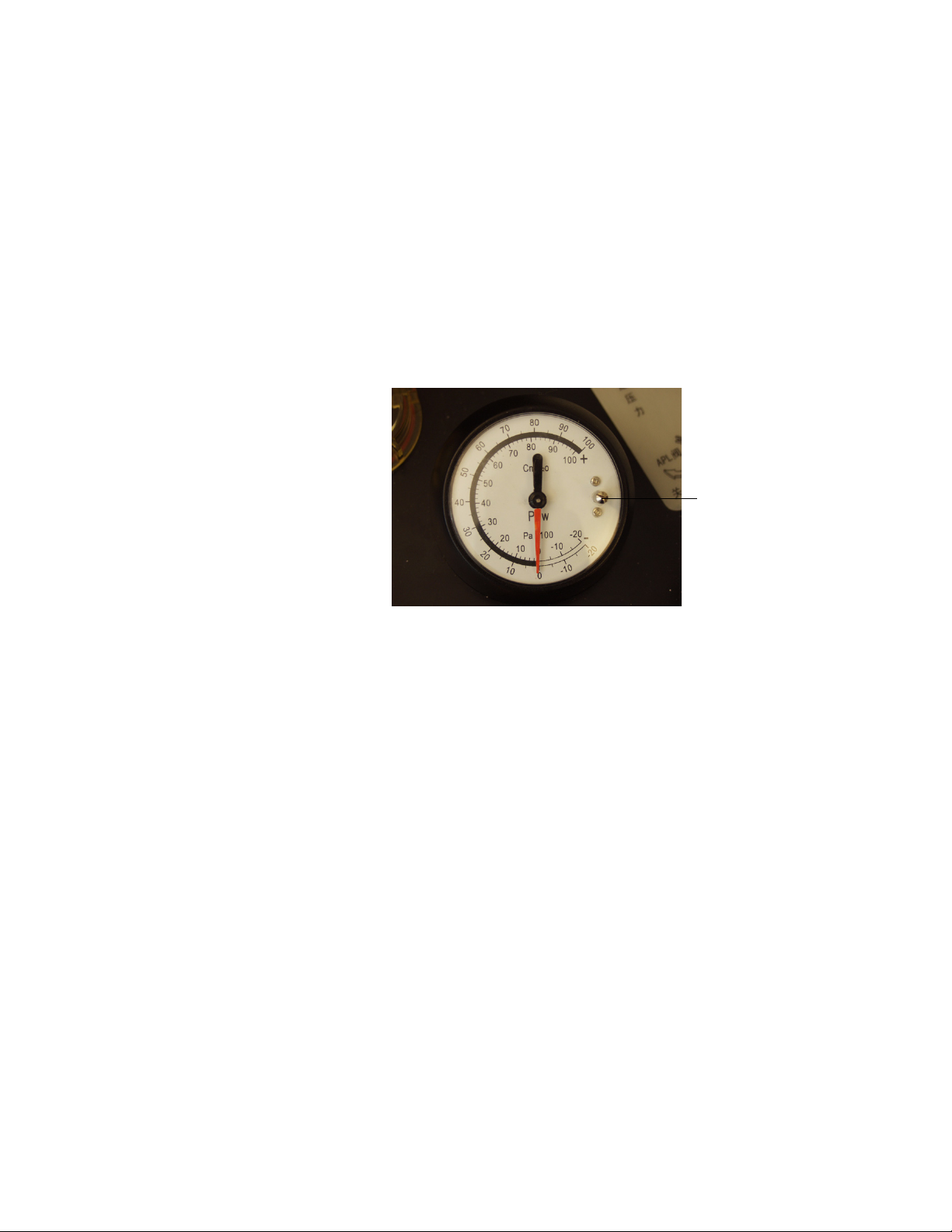
4.4 Airway pressure gauge
adjusting screw
4.4.1 Zero the
pressure gauge
1. Attach a patient circuit to the Breathing System. Leave the patient
end open.
2. Set the Manual/Mechanical ventilation switch to manual.
3. Adjust the APL valve to the maximum position.
4. Adjust the pressure gauge to zero. The adjustment screw is on
the right side of the gauge.
5. Plug the patient circuit.
6. Press and release the O
the pressure gauge.
7. Remove the plug from the patient circuit to relieve the pressure in
the circuit and recheck the zero setting of the pressure gauge.
8. If required, repeat zero and span procedure.
flush button to sweep the needle across
2
M1170718 4-9
Page 74

ZY9100
4.4.2 Checking the
pressure gauge
accuracy
The accuracy of the airway pressure gauge is checked by using the
following:
• A low-pressure test device (digital manometer or test gauge) with
an accuracy of ± 2% of reading
•A test plug
• A negative low-pressure leak test bulb
Perform this test with the system in Manual ventilation mode.
1. Make sure the pressure gauge is zeroed (Section 4.4.1).
2. Remove the bag and plug the port.
3. Disconnect the patient circuit from the inspiratory port. Connect
the low-pressure test device into the inspiratory port of the
breathing circuit.
4. Set the O
5. Fully open the APL valve to read 0 cmH
flow to 2.0 L/min.
2
O at the low-pressure
2
test device. Verify this value is the same at the breathing system
pressure gauge +
6. Close the APL valve to the point where 40 cmH
1 cmH2O.
O is read at the
2
low-pressure test device. Verify this value is the same at the
breathing system pressure gauge +
7. Fully close the O
flow control and the APL valve. Plug the
2
2 cmH2O.
expiratory port and place a negative low-pressure leak test bulb
at the bag port.
8. Squeeze the bulb until -5 cmH
O is read at the low-pressure test
2
device. Verify this value is the same at the breathing system
pressure gauge +
2 cmH2O.
4-10 M1170718
Page 75
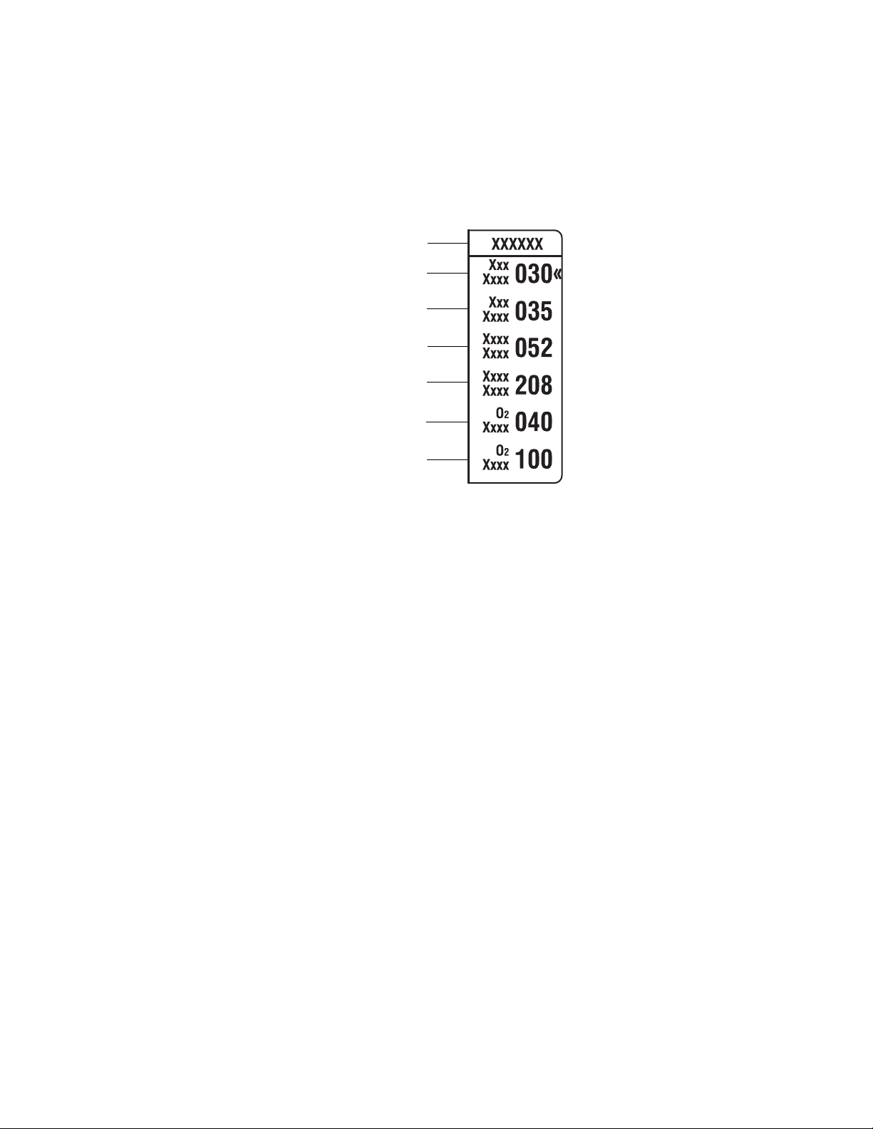
4.5 Parameter calibration
SERVICE
Paw
Paw
Zero
Flow
Gain
Flow
Zero
O
2
Gain
O
2
Zero
Gain
4 Service Tests and Calibration
4.5.1 System calibration
1. Use the Service menu to calibrate the system. Enter the Service
menu by pushing and holding the
Menu key while turning on the
power switch. The Service menu displays on the screen.
2. Turn the control knob to scroll to the desired parameter, then
push the knob to select it.
3. Turn the control knob to adjust the setting, then push to confirm.
4. Verify that the reading displayed for the corresponding parameter
is correct on the screen.
5. If additional calibrations are required, repeat steps 2 - 4.
6. Turn the power Off to exit the Service menu.
M1170718 4-11
Page 76

ZY9100
4.5.2 Paw calibration To calibrate the airway pressure (Paw):
1. Close all flow control valves.
2. Turn the tidal flow valve fully clockwise (minimum).
3. Connect a patient circuit to the breathing system, with the flow
sensor and a fitting with a sample port connected at the patient
Y-piece. The patient connection should be open to room air.
4. Zero the pressure test device.
5. Connect the pressure test device to the sample port at the patient
Y-piece.
6. Set the Manual/Mechanical ventilation switch to mechanical and
push the bellows key on the display. Mechanical mode should be
used for this test because the digital readings on the screen
update every 3 seconds. In manual mode they update every 20
seconds.
7. Check pressure readings on the Normal screen. The Paw sweep
screen should be a single line and the PEAK should be 0.
8. Adjust Paw Zero on the Service screen as required. Increasing
the calibration setting reduces the displayed value, decreasing
the calibration setting increases the displayed value.
9. If unable to zero, adjust the Paw Zero setting to 35 (mid-range)
and adjust potentiometer PW2 on the main board while checking
pressure readings on the Normal screen. The Paw sweep screen
should be a single line and the PEAK should be 0.
10. Plug the bag port and the patient Y-piece to seal the breathing
circuit.
11. Set the Manual/Mechanical switch on the breathing system to
Manual (bag mode). Leave the display in Mechanical mode.
12. Use the O
breathing circuit to 30 cmH
13. Check the pressure readings on the Normal screen.
14. Adjust the Paw Gain as necessary to match the reading on the
pressure meter. Increasing the calibration setting increases the
displayed value; decreasing the calibration setting decreases the
displayed value.
15. After adjustments are done, remove the plugs from the breathing
system.
16. Verify that the pressure readings on the display return to zero.
flow controls and APL valve to pressurize the
2
O on the test device.
2
4-12 M1170718
Page 77

4 Service Tests and Calibration
4.5.3 VT calibration 1. To calibrate the tidal volume (V
•
I:E 1:2.0
•
FREQ 20
2. Connect the V
connect the test lung to the patient port.
3. Set the V
value to make the displayed value of V
value (<
+ 5% or + 20 mL). Increasing the calibration setting
reduces the displayed value, decreasing the calibration setting
increases the displayed value.
4. Set the V
value to make the displayed value of V
value (<
+ 5% or + 20 mL). Increasing the calibration setting
reduces the displayed value; decreasing the calibration setting
increases the displayed value.
5. Repeat steps 3 and 4 until readings are within tolerances.
6. If the difference between the set value and the displayed value is
+
20 mL, then:
• Calibrate the low pressure regulator (Section 4.2).
• Repeat steps 3 and 4 until readings are within tolerances.
testing instrument to the patient’s Y-piece, and
T
value to 200 mL and adjust the Flow Zero parameter
T
value to 800 mL and adjust the Flow Gain parameter
T
) set:
T
the same as the test
T
the same as the test
TE
M1170718 4-13
Page 78

ZY9100
4.5.4 Calibration of
inspired O
%
2
To calibrate the O2% of inspiration:
1. Remove the O
sensor from the breathing circuit and expose it to
2
room air.
2. Adjust the O
Zero parameter as required, so that the O2 % on the
2
Normal screen shows 21%. Increasing the calibration setting
reduces the displayed value, decreasing the calibration setting
increases the displayed value.
3. Put the O
4. Push the O
5. Input 100% O
6. Adjust the O
sensor back into the breathing circuit.
2
flush button.
2
with 5L/min flow.
2
Gain parameter so the O2% measurement on the
2
top of the display shows 98% (maximum reading is 99).
Increasing the calibration setting increases the displayed value;
decreasing the calibration setting decreases the displayed value.
4-14 M1170718
Page 79

5 Installation and Maintenance
In this section 5.1 ZY9100 Installation checklist . . . . . . . . . . . . . . . . . . . . . 5-2
5.2 ZY9100 Planned maintenance . . . . . . . . . . . . . . . . . . . . 5-3
WARNINGS Do not perform testing or maintenance on the ZY9100
anesthesia machine while it is being used on a patient.
Possible injury can result.
w Items can be contaminated due to infectious patients.
Wear sterile rubber gloves. Contamination can spread to
you and others.
w Obey infection control and safety procedures. Used
equipment may contain blood and body fluids.
M1170718 5-1
Page 80

ZY9100
5.1 ZY9100 Installation checklist
Serial Number: Date: (YY/MM/DD)
Hospital: Performed by:
1. Unpack and assemble the ZY9100 anesthesia machine.
2. Complete the System Checkout by performing the following tests:
• Inspect the system (Section 3.2).
• Power failure test (Section 3.3).
• Pipeline and cylinder tests (Section 3.4).
• Safety pressure relief valve test (Section 3.5).
• Flow control tests (Section 3.6).
•O
supply alarm test (Section 3.7).
2
• Flush flow test (Section 3.8).
• Vaporizer back pressure test (Section 3.9).
• Low-pressure leak test (Section 3.10).
• Alarm tests (Section 3.11).
• Breathing system tests (Section 3.12).
• Electrical safety tests (Section 3.13).
5-2 M1170718
Page 81

5 Installation and Maintenance
5.2 ZY9100 Planned maintenance
Serial Number: Date: (YY/MM/DD)
Hospital: Performed by:
This section covers the regular maintenance procedures (minimum
requirements) needed to make sure that the ZY9100 anesthesia
machine — including the ventilator — operates to specifications.
Parts Replacement
Replace the vaporizer port o-rings every 12 months.
Replace the batteries every 24 months.
Refer to the ZY9100 User’s Reference Manual.
Checks and Tests
Perform the following steps every 12 months after replacing the
required parts:
1. User maintenance listed below. Including disassembly,
inspection, cleaning and parts replacement as required.
• Breathing Circuit Maintenance
• Bellows Assembly Maintenance
• Bellows Assembly Tests
•O
Sensor Calibration
2
• Calibrate Pressure Sensitivity
• Calibrate Flush Valve
Refer to this manual for the following Checks and Tests:
2. Inspect the system (Section 3.2).
3. Check that the power failure alarm operates correctly
(Section 3.3).
4. Check that the pipeline gas supplies are connected and cylinders
are installed correctly (Section 3.4).
5. Check the flow control operation (Section 3.6).
M1170718 5-3
Page 82

ZY9100
6. Check vaporizer installation.
• Make sure the top of each vaporizer is horizontal (not
crooked). Adjust the vaporizer leveling knobs if necessary.
• Make sure each vaporizer is locked and cannot be removed.
• Make sure the alarms and indicators operate correctly
(Tec 6 series vaporizer).
• Make sure that more than one vaporizer cannot be turned on
at the same time.
• Make sure the vaporizers are adequately filled.
7. Turn the power switch On. Push the control knob one time to
enter Normal mode.
8. Check that the flow sensor is positioned properly at the patient
Y-connection of the breathing circuit and functioning properly.
9. Check the vaporizer back pressure (Section 3.9).
10. Test for negative low-pressure leakage or ISO 5358 or BSI
standard positive low-pressure leakage (Section 3.10).
11. Verify system alarm operation (Section 3.11).
•Test Low O
• Test High O
•Test Low V
• Test High V
• Test high airway pressure alarm
• Test sustained airway pressure alarm
•Test O
alarm
2
alarm
2
alarm
E
alarm
E
sensor disconnect alarm
2
12. Check that the ventilator functions correctly:
• Connect the test lung to the patient Y-connection.
• Set the Manual/Mechanical ventilator switch to mechanical
and push the bellows key on the display. Set V
FREQ to 12, I:E at 1:2
• Set the gas flow to minimum.
• Fill the bellows using O
• Check that mechanical ventilation starts. Check that the
bellows inflate and deflate. Check that the display shows the
correct ventilator data. Check that there are no inappropriate
alarms.
flush.
2
to 400 ml,
T
5-4 M1170718
Page 83

6 Troubleshooting
In this section 6.1 General troubleshooting . . . . . . . . . . . . . . . . . . . . . . . . 6-2
6.2 Breathing system leak test guide . . . . . . . . . . . . . . . . . . 6-4
6.2.1 Breathing system leak test . . . . . . . . . . . . . . . . . . 6-4
6.3 Ventilator troubleshooting instructions . . . . . . . . . . . . . . 6-6
6.4 Alarm messages . . . . . . . . . . . . . . . . . . . . . . . . . . . . . . 6-7
6.5 Mechanical/Electrical troubleshooting guide . . . . . . . . . 6-9
M1170718 6-1
Page 84

ZY9100
6.1 General troubleshooting
WARNING Objects in the breathing system can stop gas flow to the
patient. This can cause injury or death:
• Do not use a test plug that is small enough to fall into
the breathing system.
• Make sure that there are no test plugs or other objects
caught in the breathing system.
Problem Possible Cause Action
High Pressure Leak Pipeline leak Use a leak detector or Snoop to check for source of
leak. Repair or replace defective parts.
O
flush valve Use a leak detector or Snoop to check for source of
2
Cylinder not installed properly Make sure cylinder is correctly aligned.
Cylinder gauges Use a leak detector or Snoop to check for source of
Cylinder gaskets Use a leak detector or Snoop to check for source of
Regulator valves Use a leak detector or Snoop to check for source of
Ventilator solenoid valve Check that all tubing is connected correctly.
Low Pressure Leak
(with vaporizer mounted)
Low Pressure Leak
(with or without vaporizer)
Bellows leak Pop-off valve diaphragm not sealing
Vaporizer not installed properly Reseat vaporizer if not installed properly.
Missing or damaged o-ring on vaporizer
manifold
Loose fill port Check fill port. Tighten if loose.
Leaking port valve on vaporizer
manifold
Leak at flow control assembly If vaporizer manifold passed previous tests:
Leaking flush valve Attach pressure measuring device on fresh gas port.
properly
Bellows mounting rim loose Remove rim and pop-off valve diaphragm; reseat
Bellows improperly mounted or has a
hole or tear
leak.
Make sure tubing connections are tight.
Replace valve if defective.
Verify that T-handles are tight.
leak.
Replace gauge if defective.
leak.
Replace gasket if defective.
leak.
Replace valve if defective.
Check for leakage through the valve.
Replace the valve.
Have vaporizer serviced at vaporizer center if vaporizer
leaks.
Check condition of o-ring.
Replace if missing or damaged.
Use the Vaporizer Manifold Valve Tester to check for
leak. If test fails, tighten, repair, or replace as needed.
Remove tubing from input side of head and occlude the
ports.
Perform leak test. If test fails, replace flow control
assembly.
Note: An alternate method is to pressurize the system
and use a leak detector or Snoop to check for source of
leak.
Replace valve if device shows increased pressure.
Disassemble pop-off valve; inspect and clean seats;
reseat; reassemble.
diaphragm; snap rim into place.
Check that only the last bellows convolution is mounted
to the rim and that the ring roll is in the groove under the
rim. Inspect the bellows for damage; replace.
6-2 M1170718
Page 85
Problem Possible Cause Action
Breathing System Leak Absorber canister not installed properly Install canister properly.
Soda lime dust on canister seals Clean seals and mating surfaces.
6 Troubleshooting
O flow does not decrease
N
2
flow
with O
2
Unable to begin mechanical
ventilation
Defective flow control assembly Verify low pressure regulator calibration.
Replace flow control assembly.
No O
supply Check O2 supply.
2
Defective Manual/Mechanical
Check Manual/Mechanical ventilation switch.
ventilation switch
Defective bellows key on the display Check the bellows key on the display.
M1170718 6-3
Page 86

ZY9100
6.2 Breathing system leak test guide
Note Always perform the low-pressure leak test (Section 3.10) on the
machine before proceeding with these breathing system leak tests.
The low-pressure leak test helps to isolate the leak: to manual mode
components, to mechanical mode components, or to components
that are common to both modes.
• If you have a similar leak in both the manual mode and the
mechanical mode, consider the absorber canister area.
• If you have a larger leak in one area than the other (mechanical
or manual), the leak is most likely NOT in the absorber canister
area.
The procedures in Section 3.12 test specific components of the
breathing system for leaks.
6.2.1 Breathing
system leak test
This test checks for leaks in the mechanical and manual ventilation
mode components. It is part of the overall checkout procedure,
Section 3.10 “Breathing system tests.” It is repeated here for testing
convenience.
WARNING Objects in the breathing system can stop gas flow to the
patient. This can cause injury or death. Do not use a test
plug that is small enough to fall into the breathing system.
Make sure that there are no test plugs or other objects
caught in the breathing system.
1. Zero the pressure gauge (Section 4.4.1).
Check valves 2. Make sure that the check valves on the breathing circuit module
work correctly:
• The Inspiratory check valve rises during inspiration and falls
at the start of exhalation.
• The Expiratory check valve rises during exhalation and falls
at the start of inspiration.
Ventilator bellows 3. Ventilator bellows test:
• Set the power switch to Off.
• Set the Manual/Mechanical ventilation switch to mechanical.
• Turn all flow controls fully clockwise (closed).
• Use the test plug or your hand to close the breathing circuit at
the patient connection.
• Push the O
• The pressure must not increase to more than 15 cmH
the pressure gauge.
• If the bellows falls more than 100 mL/min (top of indicator), it
has a leak.
flush button to fill the bellows.
2
O on
2
6-4 M1170718
Page 87

Bag circuit 4. Test the manual ventilation circuit for leaks:
• Set the Manual/Mechanical ventilation switch to manual.
• Plug the bag port (use your hand or the approved test plug).
• Close the APL valve.
• Set the O
flow to 0.25 L/min.
2
• Close the patient connection (using a hand or the approved
test plug) and pressurize the bag circuit with the O
button to approximately 30 cmH
• Release the O
flush button. The pressure must not
2
O.
2
decrease. A pressure decrease large enough to see on the
gauge indicates an unacceptable leak.
APL valve 5. Test the APL valve:
• Fully close the APL valve.
• Set the total common gas flow to approximately 3 L/min and
make sure that the value on the inspiratory pressure gauge
does not exceed 85 cmH
normal.
• Fully open the APL valve.
•Set O
flow to 3 L/min. Turn any other gases off.
2
• Make sure that the value on the inspiratory pressure gauge is
less than approximately 5 cmH
• Push the O
flush button. Make sure that the value on the
2
inspiratory pressure gauge stays less than 10 cmH
• Set the O
flow to minimum and make sure that the value on
2
the inspiratory pressure gauge does not decrease below
0 cmH
O.
2
6. Remove your hand or the test plug from the patient connection.
7. Turn all flow controls fully clockwise (closed).
O. Some pressure fluctuation is
2
O.
2
6 Troubleshooting
flush
2
O.
2
WARNING Make sure that there are no test plugs or other objects
caught in the breathing system.
M1170718 6-5
Page 88

ZY9100
6.3 Ventilator troubleshooting instructions
For ventilator problems that do not generate any error or alarm
messages, even though the ventilator may not be functioning
correctly:
• Refer to Section 6.5, Mechanical/Electrical troubleshooting guide.
For ventilator problems that result in an alarm or error message:
• Refer to Section 6.4, Alarm messages.
Important If the ventilator experiences extreme electrical interference, it may
interrupt mechanical ventilation. If this interruption occurs, the
ventilator generates an internal reset function and resumes normal
operation after two seconds. For situations where continuous
electrical interference is experienced by the ventilator, causing a
continuous interruption, the ventilator's internal reset repeats until the
interference ceases.
If the electrical interference is continuously present and mechanical
ventilation is interrupted for approximately 30 seconds, the ventilator
produces a continuous beeping audio alarm. Manual ventilation of the
patient must be performed while the mechanical ventilation is
interrupted. When the electrical interference ceases, the continuous
beeping audio alarm can be silenced only by turning the anesthesia
machine power switch Off and after five seconds back On.
WARNING This system operates correctly at the electrical
interference levels of IEC 601-1-2. Higher levels can
cause nuisance alarms that may stop mechanical
ventilation.
w Manual ventilation must be performed when electrical
interference causes interruption of ventilator delivered
mechanical ventilation. Manual ventilation must be
continued until the ventilator resumes normal operation or
an alternate ventilator/anesthesia system can be used.
6-6 M1170718
Page 89

6 Troubleshooting
6.4 Alarm messages
Message Cause Action
Connect O
Disconnect! Low Paw, patient disconnected from breathing
Sensor O
2
sensor not installed in the breathing system.
2
Sensor not measuring gas in breathing circuit.
tubes.
Make sure the breathing circuit and an O
installed correctly.
• Reconnect patient to breathing circuit tubes.
• If problem persists, check or replace the
interface board to main board cable.
• If problem persists, replace the interface board.
• If problem persists, replace the main board.
High O
2
O2% is > alarm high limit setting. • Check if the O2 limit is set correctly. Check if the
sensor measures 21% O
calibrate O
sensor.
2
in room air; if not,
2
• If calibration does not pass, replace the O
sensor.
• If calibration does not pass, replace the
interface board.
High Paw Paw is > high pressure airway limit (PawH). • Check if PawH is set too low for ventilator
settings and breathing circuit.
• Look for blockages.
• Check the interface board to main board cable.
• If problem persists, replace the interface board.
• If problem persists, replace the main board.
High V
E
The minute volume is > the set high limit. • Check ventilator settings and volume output.
• Check the breathing circuit and flow sensor
connections.
• If problem persists, replace the flow sensor.
• If problem persists, check or replace the
interface board to main board cable.
• If problem persists, replace the interface board.
• If problem persists, replace the main board.
High V
TE
The tidal volume is > the set limit. • Check ventilator settings and volume output.
• Check the breathing circuit and flow sensor
connections.
• If problem persists, replace the flow sensor.
• If problem persists, check or replace the
interface board to main board cable.
• If problem persists, replace the interface board.
• If problem persists, replace the main board.
Low Battery Voltage Battery voltage is < 22 V while using backup
battery.
• Manually ventilate the patient to save power.
• Make sure power is connected and fuses are
operational.
• Check charge voltage.
• Replace charge board.
Low O
2
O2% is < alarm low limit setting. • Check if the O2 limit is set correctly.
• Check that the O
flow is sufficient.
2
• Does the sensor measure 21% O
If not, calibrate O
sensor.
2
• If calibration does not pass, replace the O
sensor.
Low Paw Peak Paw is < low Paw alarm limit setting. • Check breathing circuit connections for leaks.
• If problem persists, check or replace the
interface board to main board cable.
• If problem persists, replace the interface board.
• If problem persists, replace the main board.
sensor is
2
in room air?
2
2
2
M1170718 6-7
Page 90

ZY9100
Message Cause Action
Low V
E
Low V
TE
No O
pressure The O2 supply has failed. • Ventilate manually if necessary.
2
On Battery,
Power OK?
Sustained Paw Paw is > sustained pressure limit for 15 seconds. • Check pressure gauge to see if the indicated
Exhaled minute volume is < low limit alarm
setting.
• Check ventilator settings and volume output.
• Check the breathing circuit and flow sensor
connections.
• If problem persists, replace the flow sensor.
• If problem persists, check or replace the
interface board to main board cable.
• If problem persists, replace the interface board.
• If problem persists, replace the main board.
Exhaled tidal volume is < low limit alarm setting. • Check ventilator settings and volume output.
• Check the breathing circuit and flow sensor
connections.
• If problem persists, replace the flow sensor.
• If problem persists, check or replace the
interface board to main board cable.
• If problem persists, replace the interface board.
• If problem persists, replace the main board.
• Check O
• Connect a pipeline supply or install an O
supply pressure.
2
2
cylinder.
The mains supply is not connected or has failed
and the system is using battery power.
• Ventilate manually to save power.
• At full charge the battery permits approximately
6 hours of mechanical ventilation. Make sure
power is connected and fuses are operational.
sustained Paw is present.
• Check the breathing circuit and flow sensor
connections.
• If problem persists, replace the flow sensor.
• If problem persists, check or replace the
interface board to main board cable.
• If problem persists, replace the interface board.
• If problem persists, replace the main board.
6-8 M1170718
Page 91

6 Troubleshooting
6.5 Mechanical/Electrical troubleshooting guide
The power supply circuits are located on two modules: the AC to DC
converters are on a universal power supply (PS), the regulated power
circuits are integrated into the CPU board (IntCPU).
Symptom Probable cause Action
System on, Power
indicator on,
no display
Power indicator not on and
no battery in the circuit
No battery 1. Battery cable disconnected
Alarms display, but not
audible
Bellows does not expand
or tends to collapse during
ventilation
Bellows distended and/or
slips off base
Bellows does not descend
during inspiration
Ventilator will not turn on
when the bellows key is
pressed and Power
indicator is on
Erratic pressure waveform
Slow exhalation pressure
release
Flow waveform is inverted Sensing tubes incorrectly connected. Check that the tube closest to the patient is
No VE or VTE readings
displayed
1. Power cable to display board.
2. display board.
1. Power cord
2. AC power
3. Cable from front panel to main board
4. Power supply board
5. Membrane switch LED
2. Battery power less than 22 V while running on
battery power
3. Battery charge circuit defective
4. Defective battery
1. Speaker cable
2. Speaker
3. Main board
1. Leak in the breathing circuit
2. Bellows not installed properly
3. Tear or leak in bellows
4. Insufficient common gas flow
5. Improperly functioning pressure relief valve in
bellows assembly
1. Bellows retention problem
2. Bellows assembly exhaust restricted
3. Bellows assembly pressure relief valve
problem
1. Normal
2. Leak in breathing system
1. Display keypad
2. Display board
3. Solenoid valve
4. Main board
1. Slight to moderate drive gas leakage
2. Solenoid valve
3. Exhalation valve assembly
Sensing tubes incorrectly connected. Check that the tube closest to the patient is
1. Check power to the display board. Replace cable
if necessary.
2. Check display board for operation.
1. Is the cord plugged in?
2. Is the power outlet OK?
3. Check cable connection.
4. Verify output voltages of power supply. Replace
power supply.
5. Replace main board.
6. Replace membrane keyboard.
1. Connect cable.
2. Charge battery.
3. Replace charge board.
4. Replace battery.
1. Make sure cable is plugged in.
2. Replace speaker.
3. Replace main board.
1. Check breathing circuit and absorber for leaks.
2. Check the bellows to rim attachment. Make sure
bellows ring roll is into groove under rim.
3. Check the entire surface of the bellows. Pay close
attention to the angles in the convolutions.
4. Check that settings on flowmeters are adequate.
5. Check the pressure relief valve and seal for
damage. Reseat.
1. Check/replace bellows.
2. Check the waste gas scavenging system for high
vacuum or blockage.
3. Control port plugged or drive gas inlet hose
blocked.
1. If the common gas flow is greater than tidal
volume, the bellows may not descend.
2. Check for leaks in drive gas circuit.
1. Ensure that all cables are plugged in properly on
the display board and the main board.
2. Replace the keypad.
3. Replace the display board.
4. Replace solenoid valve.
5. Replace main board.
1. Check for leaks at tubing connections and bellows
housing.
2. Replace solenoid valve.
3. Replace the exhalation valve.
connected to the “+” port on the rear of the machine.
connected to the “+” port on the rear of the machine.
M1170718 6-9
Page 92

ZY9100
6-10 M1170718
Page 93

7 Software Installation
In this section 7.1 Firmware replacement procedure. . . . . . . . . . . . . . . . . . 7-2
CAUTION The circuit boards are electrostatic sensitive. Use an anti-
static workstation and wear a wrist grounding strap when
handling a circuit board.
WARNING After repairs are completed, always perform
thecorresponding service tests and calibrations followed
by the checkout procedure. Refer to Sections 3 and 4 of
this manual.
M1170718 7-1
Page 94
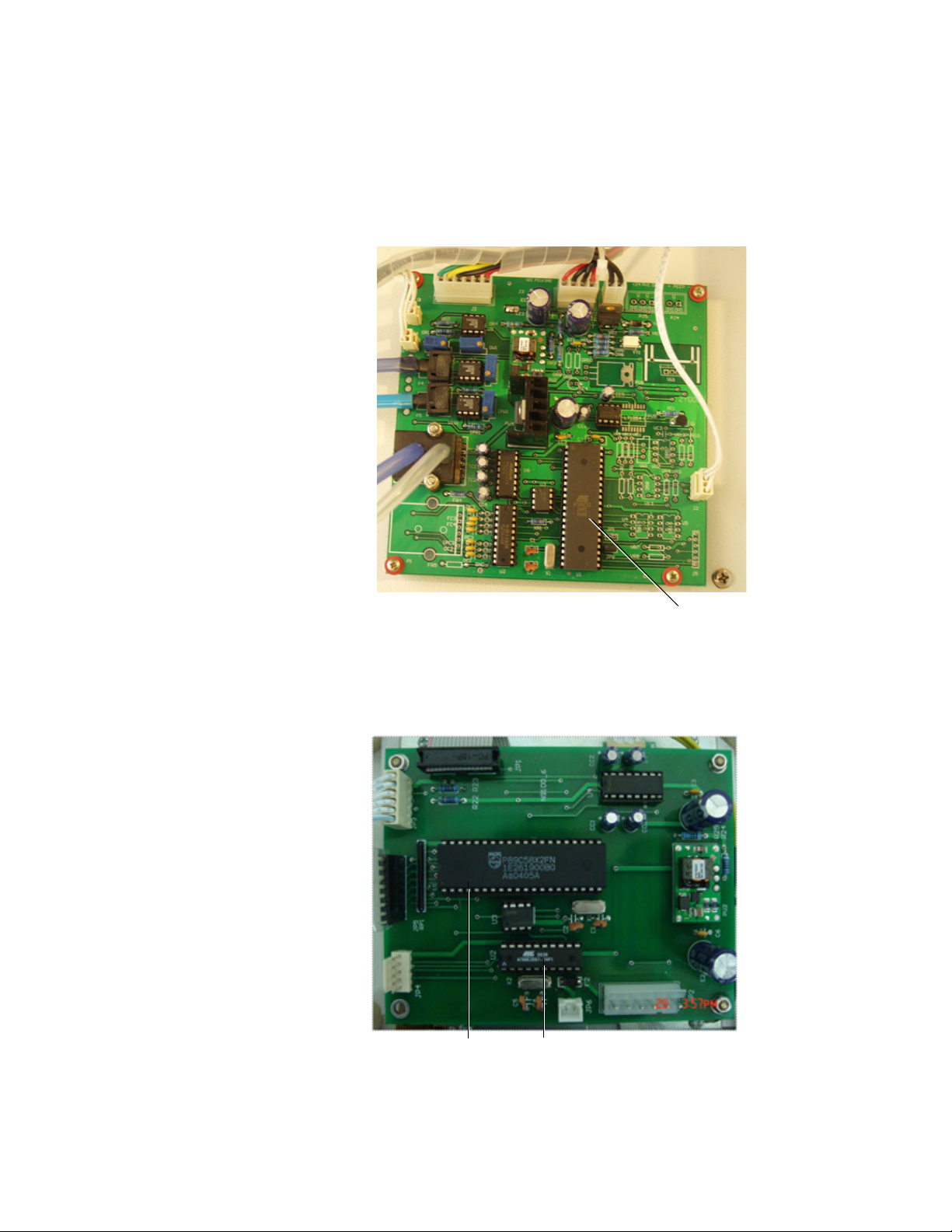
ZY9100
Replace this IC
Replace these two ICs
7.1 Firmware replacement procedure
Main board When there is a software revision:
On the main board, replace the 89C52 integrated circuit as shown in
the illustration.
Display board When there is a software revision:
On the display board, replace the 89C2051 and the 89C58 integrated
circuits as shown in the illustration.
7-2 M1170718
Page 95

8 Repair Procedures
In this section 8.1 How to bleed gas pressure from the machine . . . . . . . . 8-4
8.2 How to remove the back panels . . . . . . . . . . . . . . . . . . . 8-5
8.2.1 Upper back panel . . . . . . . . . . . . . . . . . . . . . . . . . 8-5
8.2.2 Lower back panel . . . . . . . . . . . . . . . . . . . . . . . . . 8-5
8.3 How to remove the table top panel . . . . . . . . . . . . . . . . 8-6
8.4 Replace pipeline inlet filter and check valve . . . . . . . . . 8-7
8.5 Service the cylinder supply modules . . . . . . . . . . . . . . . 8-8
8.5.1 Tightening procedure for high-pressure tube fittings
8-8
8.5.2 Replace high- pressure regulator module (complete
replacement) . . . . . . . . . . . . . . . . . . . . . . . . . . . . . . . . .8-8
8.5.3 Replace cylinder inlet filter . . . . . . . . . . . . . . . . . . 8-9
8.5.4 Replace cylinder check valve . . . . . . . . . . . . . . . . 8-9
8.6 Replace system switch assembly . . . . . . . . . . . . . . . . 8-10
8.7 Service flowmeter module . . . . . . . . . . . . . . . . . . . . . . 8-11
8.8 Service vaporizer manifold parts . . . . . . . . . . . . . . . . . 8-12
8.8.1 Repair manifold port valve . . . . . . . . . . . . . . . . . 8-12
8.8.2 Checkout procedure for manifold port valve . . . . 8-12
8.8.3 Replace common gas check valve . . . . . . . . . . . 8-13
M1170718 8-1
Page 96

ZY9100
8.8.4 Replace vaporizer manifold . . . . . . . . . . . . . . . .8-13
8.9 Replace APL valve . . . . . . . . . . . . . . . . . . . . . . . . . . . 8-14
8.10 Replace Manual/Mechanical ventilation switch . . . . . 8-15
8.10.1 Replace Manual/Mechanical ventilation switch . 8-15
8.10.2 Replace switch shaft . . . . . . . . . . . . . . . . . . . . . 8-15
8.10.3 Test in manual ventilation mode . . . . . . . . . . . . 8-17
8.10.4 Test in mechanical ventilation mode . . . . . . . . . 8-17
8.11 Replace the disc seat of inspiratory/expiratory check
valves . . . . . . . . . . . . . . . . . . . . . . . . . . . . . . . . . . . . . . . . . 8-18
8.11.1 Replace the disc seat of inspiratory/expiratory check
valves . . . . . . . . . . . . . . . . . . . . . . . . . . . . . . . . . . . . . . 8-18
8.11.2 Check Valve Test . . . . . . . . . . . . . . . . . . . . . . . 8-18
8.12 Replace casters . . . . . . . . . . . . . . . . . . . . . . . . . . . . . 8-19
8.13 Replace task light and switch . . . . . . . . . . . . . . . . . . . 8-20
8.14 Electrical enclosure components . . . . . . . . . . . . . . . . 8-21
8.14.1 Charge board . . . . . . . . . . . . . . . . . . . . . . . . . .8-22
8.14.2 Power supply . . . . . . . . . . . . . . . . . . . . . . . . . .8-22
8.14.3 Battery . . . . . . . . . . . . . . . . . . . . . . . . . . . . . . . . 8-22
8.15 Replace the membrane of exhalation valve . . . . . . . . 8-24
8-2 M1170718
Page 97

WARNING To prevent fires:
• Use lubricants approved for anesthesia or O2
equipment, such as Krytox.
• Do not use lubricants that contain oil or grease; they
burn or explode in high O2 concentrations.
• All covers used on the system must be made from
antistatic (conductive) materials. Static electricity can
cause fires.
w Obey infection control and safety procedures. Used
equipment may contain blood and body fluids.
w A movable part or a removable component may present a
pinch or a crush hazard. Use care when moving or
replacing system parts and components.
8 Repair Procedures
w Some internal parts have sharp edges and can cause
cuts or abrasions. Use care when servicing internal
components.
w When servicing the ventilator, extreme care must be
taken to avoid introducing foreign debris, particularly
metal chips generated by screw threads, into the
pneumatic flow passages of the ventilator. Failure to do
so can result in damage to the flow valve and possible
injury to the patient.
w After repairs are completed, always perform the
correponding service tests and calibrations followed by
the checkout procedure. Refer to Sections 3 and 4 of this
manual.
CAUTION Electrostatic discharge through circuit boards may
damage the components on them. Wear a static control
wrist strap before touching the circuit boards. Handle all
circuit boards by their non-conductive edges. Use antistatic containers when transporting them.
M1170718 8-3
Page 98

ZY9100
8.1 How to bleed gas pressure from the machine
Before disconnecting pneumatic fittings, bleed all gas pressure from
the machine.
1. Close all cylinder valves and disconnect all pipeline supplies from
the source.
Note: If the machine includes N
pipeline.
If pipeline O
is not available, open the O2 cylinder valve.
2
2. Turn the flow controls for all gases (except O
counterclockwise.
3. Make sure that all cylinder and pipeline gauges read zero before
proceeding.
• For machines with N
2
from the source (or close the O
• Push the O
flush button to bleed O2 from the system.
2
O, do not disconnect the O2
2
O, disconnect the O2 pipeline supply
cylinder valve).
2
) at least one turn
2
8-4 M1170718
Page 99

8.2 How to remove the back panels
You must remove the back panels to repair or replace many of the
machine’s components.
8 Repair Procedures
8.2.1 Upper back panel
8.2.2 Lower back panel
1. Bleed all gas pressure from the machine.
2. Make sure that the pressure reading in all pipelines is 0.
3. Unplug the power plug.
4. Unscrew the eight screws attaching the panel to the frame.
Remove the panel.
1. Bleed all gas pressure from the machine.
2. Make sure that the pressure reading in all pipelines is 0.
3. Unplug the power plug.
4. Unscrew the six screws attaching the panel to the frame. Remove
the panel.
M1170718 8-5
Page 100
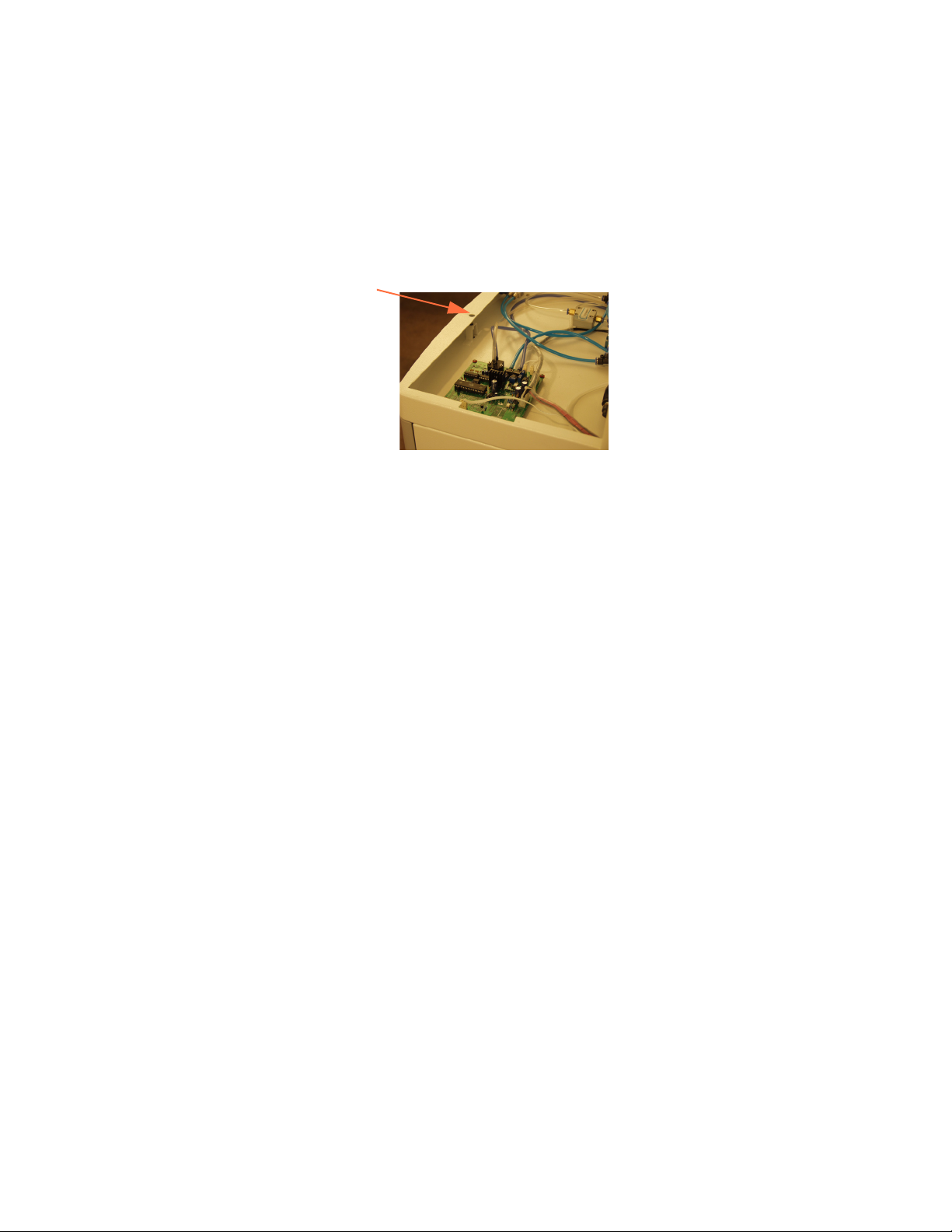
ZY9100
8.3 How to remove the table top panel
The table top assembly is attached with hooks located under the
panel and one steel bolt.
To remove the table top panel:
1. Use a 4 mm hex wrench to unscrew the bolt. This is accessed
from under the table top by opening the top drawer.
2. Slide the table forward and lift.
8-6 M1170718
 Loading...