

Page 1
g
GE Consumer Home Services Training
TECHNICAL SERVICE GUIDE
Advantium™ Built-In Oven
MODEL SERIES:
SCB2000
SCB2001
ZSC2000
ZSC2001
TM
PUB # 31-9057 08/00
Page 2

!
IMPORTANT SAFETY NOTICE
The information in this service guide is intended for use by
individuals possessing adequate backgrounds of electrical,
electronic, and mechanical experience. Any attempt to repair a
major appliance may result in personal injury and property
damage. The manufacturer or seller cannot be responsible for the
interpretation of this information, nor can it assume any liability in
connection with its use.
WARNING
To avoid personal injury, disconnect power before servicing this
product. If grounding wires, screws, straps, clips, nuts, or washers
used to complete a path to ground are removed for service, they
must be returned to their original position and properly fastened.
GE Consumer Home Services Training
Technical Service Guide
Copyright © 2000
All rights reserved. This service guide may not be reproduced in whole or in par t
in any form without written permission from the General Electric Company.
Page 3
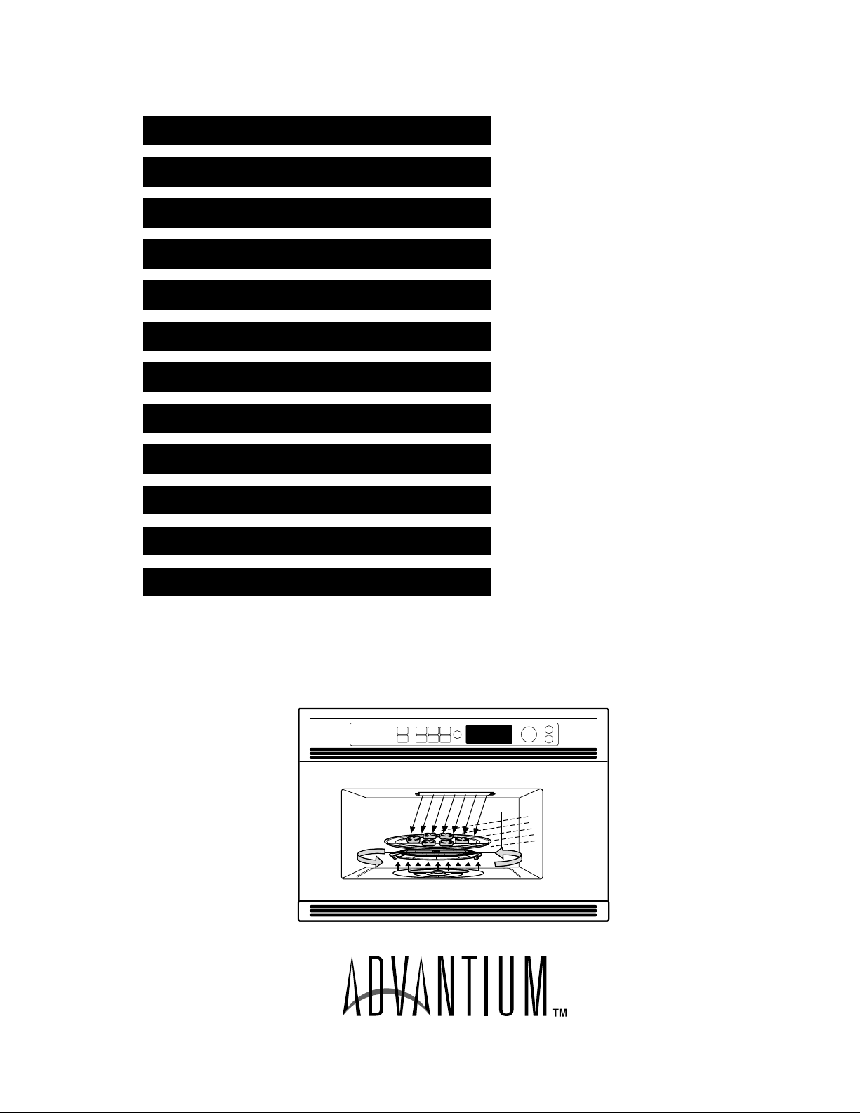
Table of Contents
T able of Contents
Welcome to Advantium . . . . . . . . . . . . . . . . . . . . . . . . . . . . . . . . . . . . . . . . . . . . 2
Installation Instructions . . . . . . . . . . . . . . . . . . . . . . . . . . . . . . . . . . . . . . . . . . . 4
Specifications . . . . . . . . . . . . . . . . . . . . . . . . . . . . . . . . . . . . . . . . . . . . . . . . . . 10
Warranty Information. . . . . . . . . . . . . . . . . . . . . . . . . . . . . . . . . . . . . . . . . . . . . 11
Overview of Advantium . . . . . . . . . . . . . . . . . . . . . . . . . . . . . . . . . . . . . . . . . . 12
Control Panel Features . . . . . . . . . . . . . . . . . . . . . . . . . . . . . . . . . . . . . . . . . . 13
How to Speedcook . . . . . . . . . . . . . . . . . . . . . . . . . . . . . . . . . . . . . . . . . . . . . . 15
Operating Characteristics . . . . . . . . . . . . . . . . . . . . . . . . . . . . . . . . . . . . . . . . 16
Mechanical Disassembly . . . . . . . . . . . . . . . . . . . . . . . . . . . . . . . . . . . . . . . . . 26
Troubleshooting . . . . . . . . . . . . . . . . . . . . . . . . . . . . . . . . . . . . . . . . . . . . . . . . 41
Schematics and Wiring Diagrams . . . . . . . . . . . . . . . . . . . . . . . . . . . . . . . . . . 48
Illustrated Parts Breakdown . . . . . . . . . . . . . . . . . . . . . . . . . . . . . . . . . . . . . . 54
– 1 –
GEA00403
Page 4
Welcome to
TM
The new Advantium™ oven uses breakthrough
speedcook technology to cook food with light.
Foods cook in a fraction of the time needed in
conventional ovens , with delicious results .
Advantium browns, bakes, roasts, broils, and
crisps just like a conventional oven, and requires
no preheating. Advantium uses high-intensity
halogen lights to cook food from the top and
bottom simultaneously, cooking the surface and
interior to seal in moisture and flavor. For added
convenience, the Advantium oven can be
converted to a fully functional microwave by simply
pressing a button.
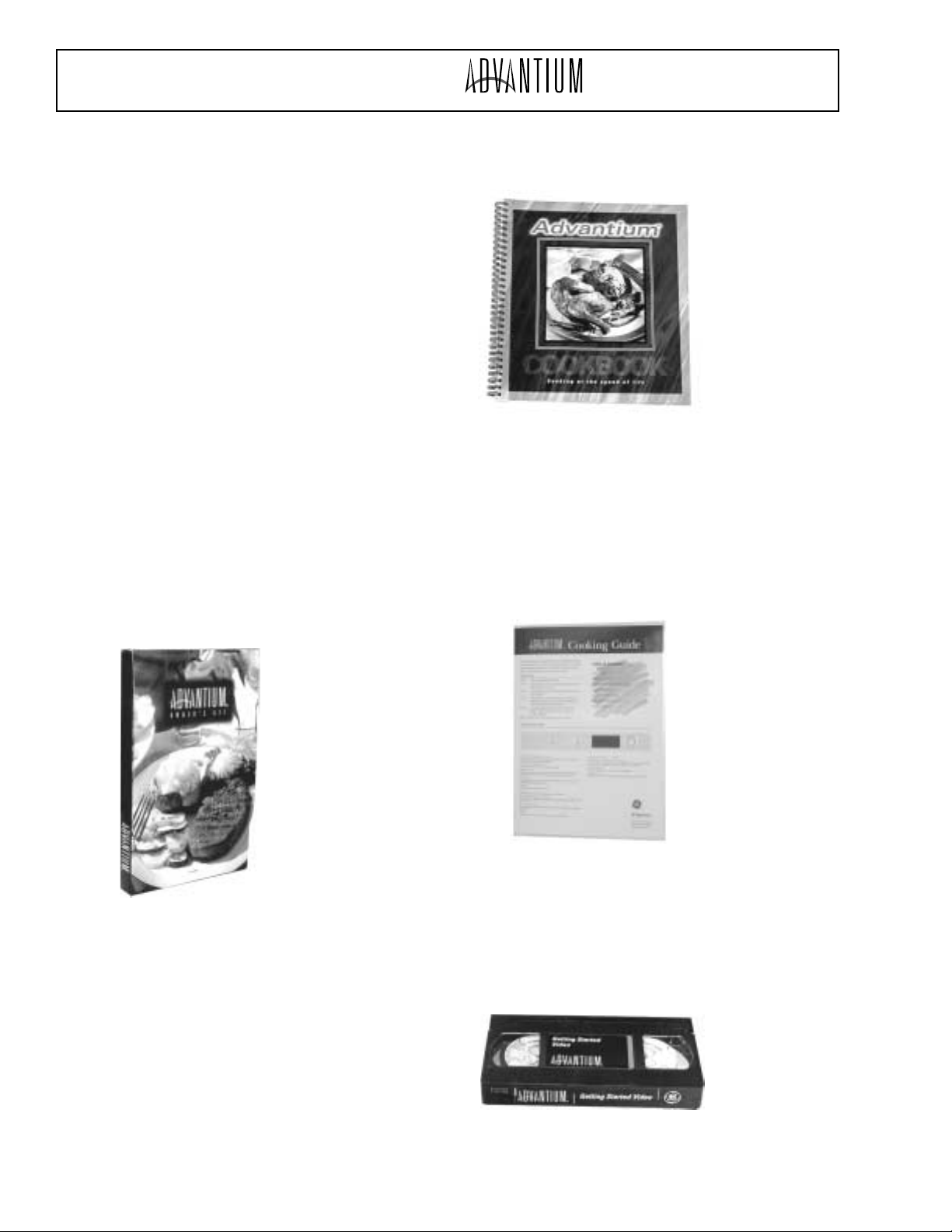
Advantium™ Owner’s Kit
Included with the purchase of the Advantium™
oven is an Advantium™ Owner’s Kit. The kit
includes the following helpful tools and literature:
• 136-page cookbook
• 4-page cooking guide
• Owner’s Manual (use & care guide)
•“Getting Started” video (17:37 min.)
• Cleaning scraper
the cookbook for proper cookware selection and
food placement on the turntable surface.
Pub. No. 49-40070
Cooking Guide
The cooking guide is a four-page, quick-reference
guide containing numerous helpful cooking tips.
In addition, it contains helpful use and care
information and two pages of information which
will assist the consumer in adapting their favorite
recipe for the Advantium oven.
Pub. No. 28-X139
Cookbook
The cookbook includes numerous recipes, helpful
cooking tips, information on proper cooking
techniques, and proper use of cookware for
various types of recipes. The cookbook is also a
helpful diagnostic tool when servicing an
Advantium™ oven for a cooking issue. Be sure to
reference the cookbook prior to servicing a unit for
any cooking concern. Be sure that the customer
is following the proper selections for the type and
size of food. Also be sure to consult the front of
Pub. No. 49-40122
“Getting Started” Video (17:37 min.)
The “Getting Started” video provides general
information on proper use and care, and is
intended to help the consumer during their initial
use of the product (getting started).
Pub. No. 28-X060
– 2 –
Page 5
Owner’s Manual
The Owner’s Manual provides the customer with
detailed information on the operation, use, and
care of their product. It also contains a section on
helpful troubleshooting tips.
GE Appliances
Owner s Manual
. . . . . . . . . . . . . . .34
SCB2000
. . . . . . . . . . . . . . .32
. . . . . . . . . . . . . . . .34
SCB2001
. . . . . . . . . . . . . . . . . . .10, 32
. . . . . . . . . . . . .32
. . . . . . . . . . . . . . . . . . . . . .33
. . . . . . . . . . . . . . . . . . . .32
. . . . . . . . . . . . . . . . .32
. . . . . . . . . . . . . . . . . . . . .34
. . . . . . . . .35—36
. . . . . . . . . . . .37
. . . . . . . . . . . . . . . . . .36
. . . . . . . . . . . . .38, 39
. . . . . . . . . . . .8
. . . . . . . . .41, 42
. .Back Cover
. . . . . . . . . . . . . . . . . . . . .43
Part No. 164D3370P099 Pub. No. 49-40101 3-00 JR
Pub. No. 49-40101
“
Advantium Oven
http://geadvantium.com
Advantium
Advantium Quick Start
Cooking controls
. . . . . . . . . . . . . . .13
Customer information
. . . . . . . . . . . .8
Oven features
. . . . . . . . . . . . . . . . .12
What is Advantium?
. . . . . . . . . . . . .9
Safety
. . . . . . . . . . . . . . . . . . . . . .2—7
Speedcooking
Cooking tips
. . . . . . . . . . . . . . . . . .15
Custom speedcook recipes
Custom speedcook recipe log
Manual speedcook
. . . . . . . . . . . . .17
Power level
. . . . . . . . . . . . . . . . . . .16
Repeat last
. . . . . . . . . . . . . . . . . . .15
Resume feature
. . . . . . . . . . . . . . .15
Speedcook cookware
. . . . . . . . . . .17
Speedcook menu guide
Speedcook-safe cookware
Things that are normal
Using a pre-set speedcook menu
Microwaving
Cooking tips
. . . . . . . . . . . . . . . . . .23
Custom microwave recipes
Custom microwave recipe log
Defrost (auto)
. . . . . . . . . . . . . . . . .26
Defrost (time)
. . . . . . . . . . . . . . . . .26
Defrosting tips
. . . . . . . . . . . . . . . . .27
Micro Express
. . . . . . . . . . . . . .11, 23
Microwave power levels
Microwave-safe cookware
Precautions to avoid possible
exposure to excessive
microwave energy
. . . . . . . . . . . . . .2
Sensor cooking
. . . . . . . . . . . .28—29
Things that are normal
Time cook
. . . . . . . . . . . . . . . . . . . .23
Using pre-set
microwave selections
. . . . . . . . . . .22
. . . . . . . . . .10
. . . . . . . . .11
. . . . . . . . . .21
. . . . . . . . .23
. . . . . . . . . .30
. . . . . . . . .5
. . . . . . . .6
Other Features
Automatic fan
Beeper volume
Child lockout
Clock
Display ON/OFF
Help
Review
Scroll speed
Timer
. . .18—19
. . . .20
Care and Cleaning
Cleaning the inside
Cleaning the outside
Lamp covers
Troubleshooting
Problem Solver
Customer Service
. .14
Customer information
Product Registration
Service phone numbers
. . .24—25
Warranty
. . . .24
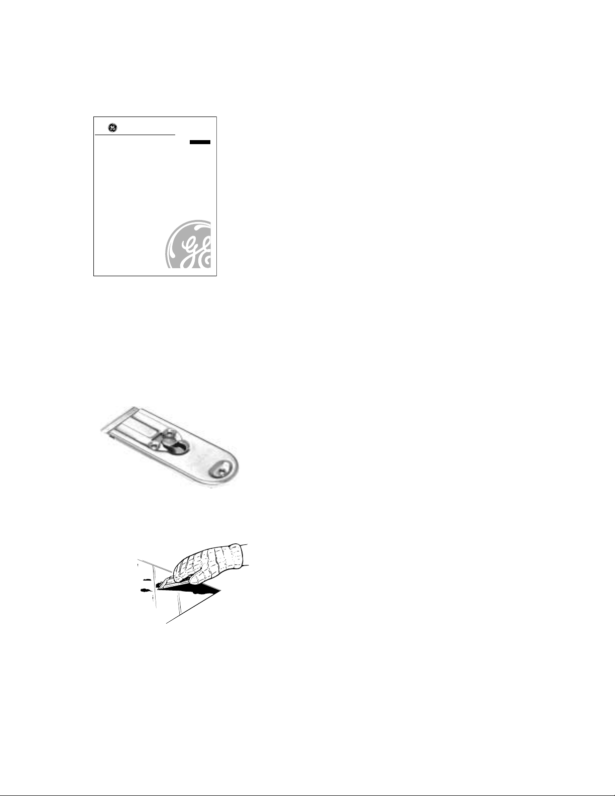
Scraper/Cleaner
The last item included in the Advantium™
Owner’s Kit is a scraper/cleaner. This tool is
included in order to aid the consumer in cleaning
the upper and lower halogen lamp covers. These
covers must be kept clean in order to ensure
maximum cooking efficiency.
GEA00410
For heavy or burned on soil
GEA00411
WX5X1614
– 3 –
Page 6
Installation Instructions
Before you begin — Read these instructions
completely and carefully.
• Save these instructions for local inspector’s use.
• Observe all governing codes and ordinances.
Note to Installer: Be sure to leave these
instructions with the consumer.
Note to Consumer: Keep these instructions with
your Owner’s Manual for future reference.
WARNING: This appliance must be properly
grounded. See “Electrical Requirements” in this
section.
Proper installation is the responsibility of the
installer. Product failure due to improper
installation is not covered under the GE Appliance
Warranty. See the Owner’s Manual for warranty
information.
Use this appliance only for its intended purpose.
Caution: This o ven should be installed by a
qualified installer or service technician.
• Never use the oven for warming or heating a
room. Prolonged use of the oven without adequate
ventilation can be hazardous.
Check with local utilities for electrical codes that
apply in your area. Local codes vary. Installation of
electrical connections and grounding must comply
with applicable codes. In the absence of local
codes, the oven should be installed in accordance
with National Electrical Code ANSI/NFPA 70 or
latest edition.
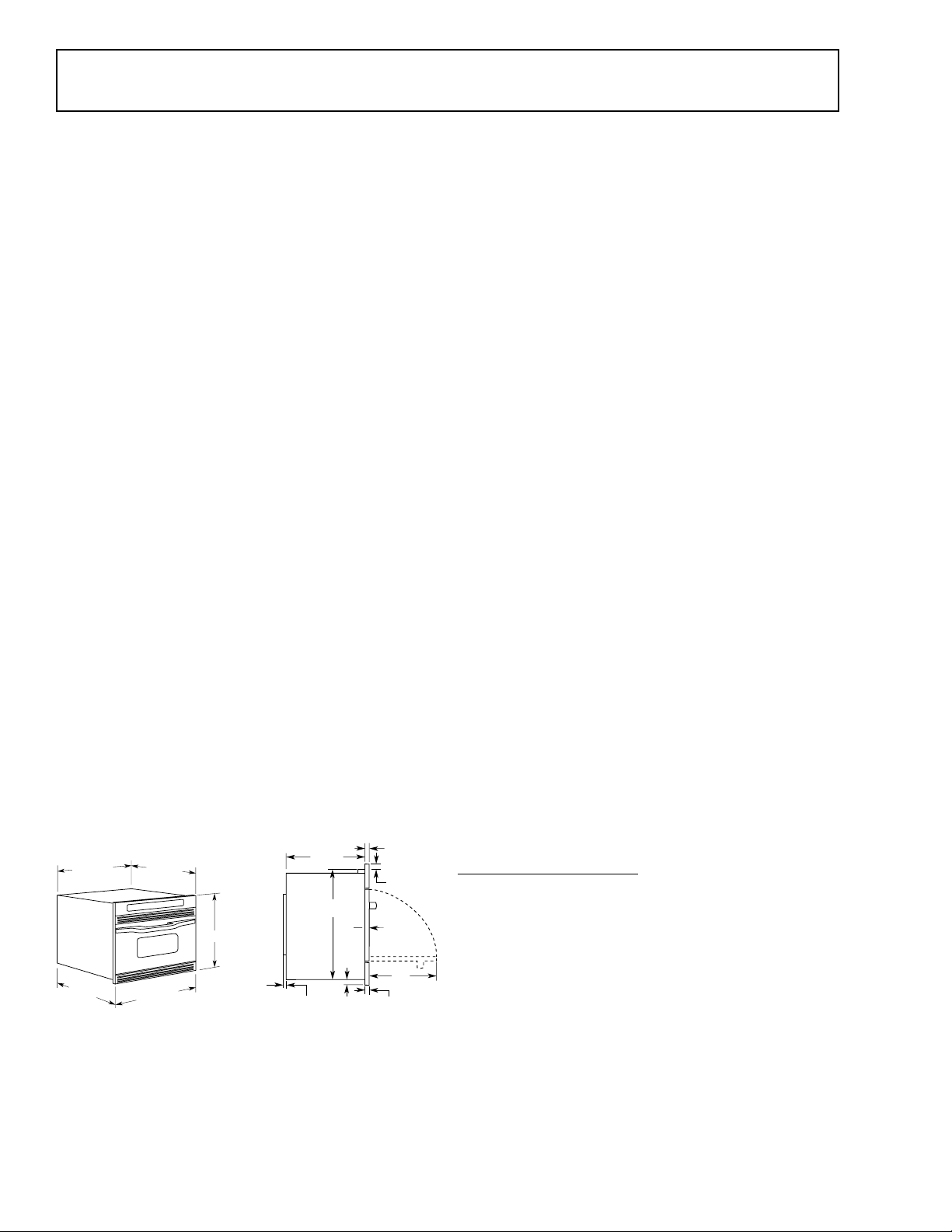
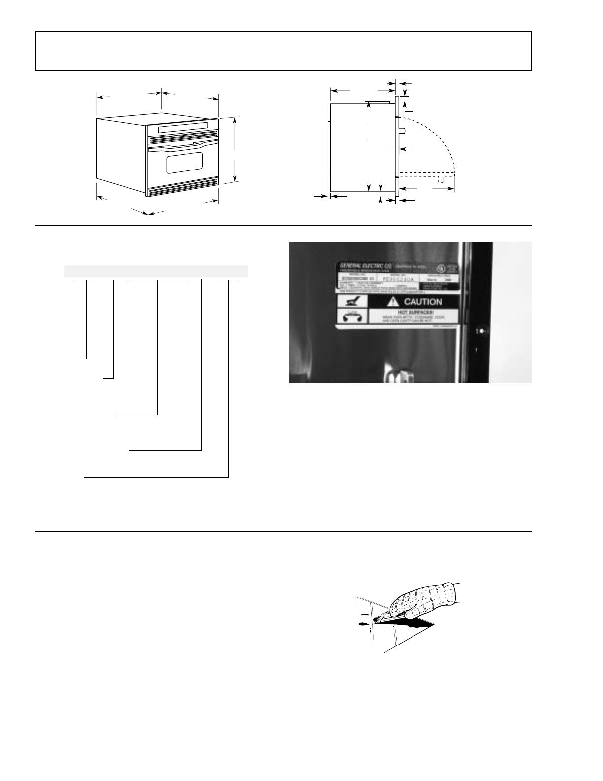
Product Dimensions
28-7/16"
15-27/32"
15"
(Recessed
Portion)
29-25/32"
21-7/8"
GEA00354
14-1/8"
20-27/32"
15/32"
11/16"7/8"
27/32"
9/16"
27/32"
13"
GEA00355
Advance Planning
• This oven may be installed directly into a wall
or wall oven cabinetry, 30 in. minimum width.
• The front surface of the oven will be nearly
flush with surrounding cabinetry doors.
• This oven can be installed over any GE single
electric built-in oven or a single GE electric
built-in warming drawer.
• This oven must be installed at least 36 in.
above the floor.
WARNING: For personal safety, this oven cannot
be installed in a cabinet arrangement such as an
island or peninsula.
Caution: This oven is not approved for use above
another built-in speedcook oven, side-by-side, or
under-the-countertop installations.
• Cabinets installed adjacent to wall ovens must
have an adhesion specification of at least 194°F
temperature rating.
• Allow for clearance to adjacent corners, walls,
drawers, etc.
Tools and Materials Required
• 2 x 4 or 2 x 2 lumber for runners
• Saw
• Level
• Drill and 3/32-in. bit
• Phillips screwdriver
• Wood screws and adhesive or other hardware
for installing runners or shelf to support oven
Electrical Requirements
• Junction box
• Electrical cable - 3-conductor or 4-conductor
wire, as required by local codes
• UL-listed conduit connector
• Wire cutters and wire stripper
– 4 –
Page 7
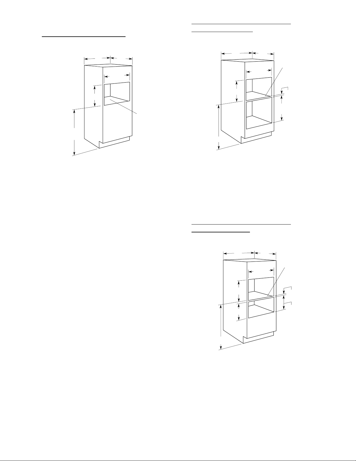
Prepare the Opening
Single Speedcook Installation
Speedcook Oven Installed Above a
GE Built-In Wall Oven
30"
21"
36-3/4" Min.
Required
19"
Min
28-1/2"
Construct Solid
Bottom Min. 3/8"
Plywood
Supported by
2 x 4 or 1 x 2
Runners, all
Four Sides
GEA00356
Order a 30-in. wide single oven cabinet or cut the
opening in a wall to dimensions shown.
The rough opening must be:
• Depth - 19 in. min.
• Width - 28-1/2 in. min.
• Height - 21 in. min.
• 36-3/4 in. from the floor to the cutout is
required.
• These ovens require 3/4-in. overlap on each
side, top, and bottom of the cutout.
• Oven overlaps will conceal cut edges on all
sides of the opening.
When installed over a single oven or a warming
drawer, allow at least 2 in. between the two
openings. This separation will provide clearance
for bottom over lap of the speedcook oven and top
overlap of the single oven or warming drawer.
• Construct a solid oven floor of 3/8-in. min. thick
plywood supported by 2 x 4 or 1 x 2 runners
on all sides.
• The support must be level and rigidly
mounted, flush with the bottom edge of the
cutout.
WARNING: For personal safety, the mounting
surface must be capable of supporting the cabinet
load, in addition to the added weight of this
approximately 100-lb. product plus additional oven
loads of up to 50 lb., or a total weight of 150 lb.
24"
30"
21"
*45-1/4"
* If you are replacing a GE electric double oven with the
combined installation of a speedcook and single wall oven,
use the dimensions shown. The middle rail separating the two
openings may need to be larger than the 2 in. min. shown.
Min.
28-1/2"
Construct Solid
Bottom Min. 3/8"
Plywood
Supported by
2 x 4 or 1 x 2
Runners, all
Four Sides
2" Min.
Per Oven
Requirement
GEA00357
• Always maintain 36-3/4 in. min. distance from
the floor to the speedcook oven cutout in any
installation combination.
Speedcook Oven Installed Above a
GE Warming Drawer
30"
21"
9-1/4"
36-3/4" Min.
Note: Additional clearance between the cutouts may be
required. Check to be sure the oven supports above the
warming drawer location do not obstruct the required interior
23-1/2 in. depth and 9-1/4 in. height. See Installation
Instructions for details.
24"
Min.
28-1/2"
Construct Solid
Bottom Min. 3/8"
Plywood
Supported by
2 x 4 or 1 x 2
Runners, all
Four Sides
2" Min.
Install 2 x 4
or 2 x 2
Runners or
Solid Bottom,
Must Support
100 lbs.
GEA00358
– 5 –
Page 8
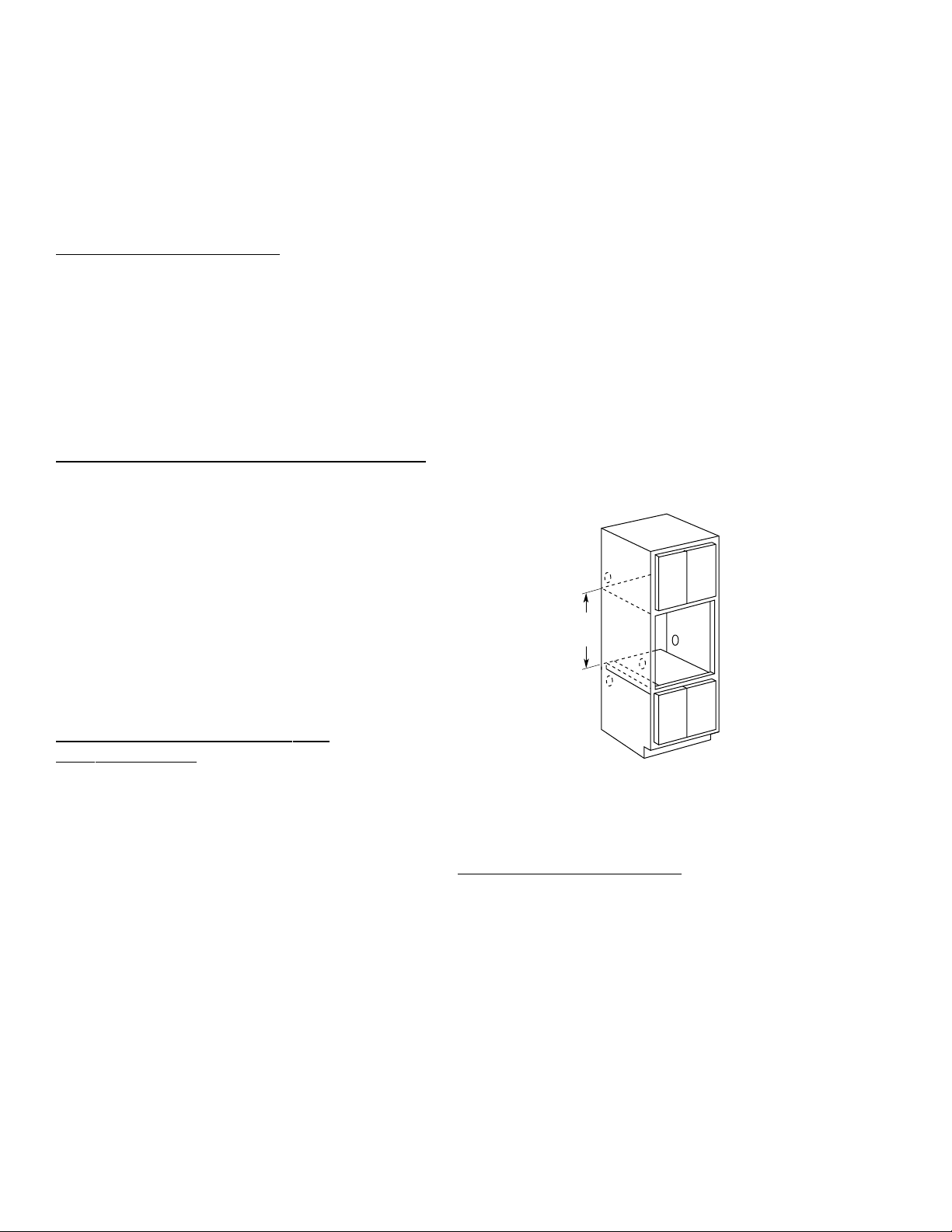
When installing the speedcook oven over a GE
21"
Min.
GEA00359
electric warming drawer, follow the product
installation instructions.
• An anti-tip block must be installed at the rear
of the warming drawer opening. Again, see
Installation Instructions for complete details.
• Do not have a fuse in the NEUTRAL or
GROUNDING circuit. A fuse in the NEUTRAL or
GROUNDING circuit could result in an electrical
shock.
• Check with a qualified electrician if you are in
doubt as to whether the appliance is properly
grounded.
Electrical Requirements
Single Speedcook Installation
Product rating is 120/208 or 120/240V, 60 Hz, 30
amps. This product must be connected to a supply
circuit of the proper voltage and frequency and
protected by a time delay fuse or circuit breaker.
The power supply should be brought to a separate
30 ampere branch circuit. Wire size must confor m
to the requirements of the National Electric Code
or the prevailing local code.
Combined Speedcook and Wall Oven Installation
When installed in combination with a GE single
wall oven, use separate electrical junction boxes,
or
Install a single junction box connected to 50 amp.
supply circuit or properly rated supply circuit.
• Refer to single oven installation instructions for
electrical requirements of that product.
• These connections must be made by a
qualified electrician. All electrical connections
must meet National Electrical Code or
prevailing local codes.
Failure to follow these instructions could result in
serious injury or death.
Install Junction Box
Note: The conduit is located at the top right on the
back of the oven.
Locate and install the junction box within reach of
the oven conduit:
• Through the left or right sides of the cabinet
wall and into adjacent cabinet, or
• Through the cutout floor, or
• In the upper cabinet.
Combined Speedcook and Warming
Drawer Installation
When installing the speedcook oven over a GE
electric warming drawer, a separate 120V, 60Hz,
properly grounded receptacle must be installed.
See instructions packed with the warming drawer.
WARNING: Electrical Shock Hazard
• The electrical power to the oven branch circuit
must be shut off while line connections are being
made.
• Use copper wiring only.
• Electrical ground is required on this appliance.
The free end of the green wire (the ground wire)
must be connected to a suitable ground. This wire
must remain grounded to the oven.
• If cold water pipe is interrupted by plastic, nonmetallic gaskets, union connections, or other
insulating materials, do not use for grounding.
• Do not ground to a gas pipe.
Installation
Remove Packaging and Parts
1. Open the door and remove packing material
with ceramic tray.
2. Locate Owner’s Kit in carton. Remove and
save.
3. Locate box with metal trays in carton. Remove
and save.
4. Locate parts package containing 5 mounting
screws (4 required, 1 extra).
Caution: To protect the bottom trim, do not
remove the styrofoam shipping base until the oven
is slipped into the opening.
– 6 –
Page 9
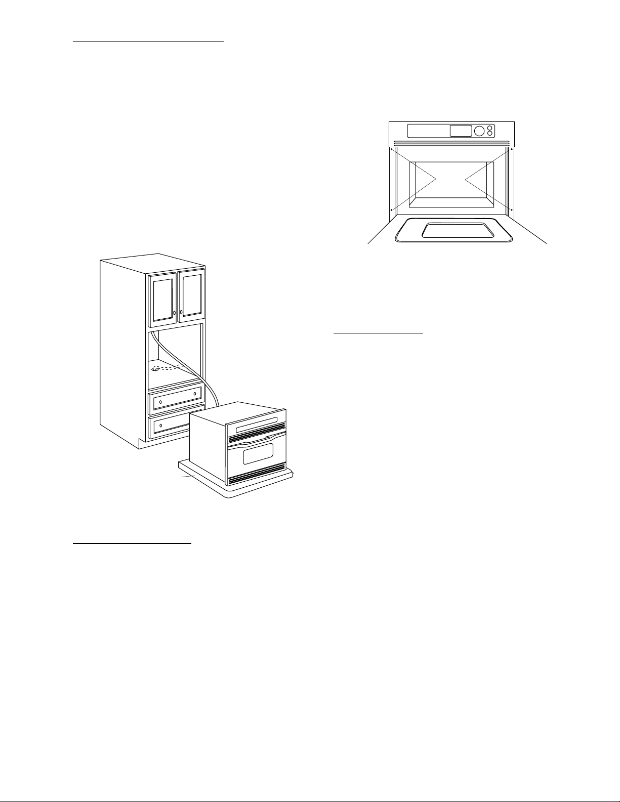
Route Conduit Through Cutout
Caution: Two people are required to lift the oven
into the opening. Grasp the bottom at front and
rear. Discard styrofoam base. Do not use the
oven handle to lift the oven. Damage will
occur!
1. With the oven in front of the cabinet opening,
insert conduit into cabinet opening.
WARNING: Securely fasten oven to cabinet using
the screws provided. Failure to do so could cause
the oven to move or tip during use and result in
personal injury.
3. Secure oven to cabinet with screws supplied.
2. Lift the oven into the opening while continuing
to feed the conduit in the direction of the
installed junction box. Be sure the conduit
does not get pinched between the back of the
oven and the cabinet wall.
Styrofoam
Shipping Base
GEA00360
Attachment
Screws
Secure Oven To Cabinet
With Screws Provided
CAUTION
GEA00361
Connect Electrical
WARNING: Electrical Shock Hazard
• Electrical ground is required on the appliance.
• Do not connect the electrical supply until
appliance is permanently grounded.
• Disconnect power to the junction box before
making the electrical connection.
• This appliance must be grounded to a metallic,
permanent wiring system, or a grounding
connector should be connected to the grounding
terminal or wire lead on the appliance.
• Failure to do so could result in fire, personal
injury, or electrical shock.
Secure Oven to Cabinet
1. Slide oven into the cabinet opening.
2. Drill 3/32-in. pilot holes into the cabinet frame
through the 4 mounting holes in the oven’s
front frame.
– 7 –
Page 10
GEA00362
GEA00363
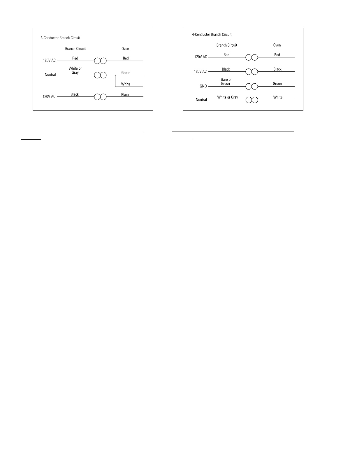
When Connecting to a 3-Conductor Branch
Circuit:
1. Connect oven red lead to branch circuit red
lead.
2. Connect oven black lead to branch circuit
black lead.
3. Connect oven green ground lead and white
lead to branch circuit neutral (white or gray).
When Connecting to a 4-Conductor Branch
Circuit:
1. Connect oven red lead to branch circuit red
lead.
2. Connect oven black lead to branch circuit
black lead.
3. Break connection between oven white lead
and oven green ground lead.
4. Connect oven white lead to branch circuit
neutral lead (white or gray).
5. Connect oven green ground lead to branch
circuit ground lead (green or bare copper).
– 8 –
Page 11

Notes
– 9 –
Page 12
Specifications
GEA00412
15"
(Recessed
28-7/16"
15-27/32"
Portion)
29-25/32"
GEA00354
Nomenclature
SCB2000CBB
Speedcook Oven
Configuration
A = Above the cooktop
B = Built-in style
21-7/8"
14-1/8"
20-27/32"
15/32"
27/32"
9/16"
27/32"
13"
11/16"7/8"
GEA00355
GEA00414
Feature Package
2000 = Color model
2001 = Stainless steel
Model Year Designator
Color
WW = White on white
BB = Black on black
CC = Bisque
AA = Almond on almond
SS = Stainless steel
GEA00413
Cleaning
Clean the inside of the oven after each use. Some
spatters can be removed with a paper towel,
others may require a warm soapy cloth. Remove
greasy spatters with a sudsy cloth, then rinse with
a damp cloth.
Do not use abrasive cleaners or sharp utensils on
oven walls. Never use a commercial oven
cleaner on any part of your oven. Do not clean
the inside of the oven with metal scouring pads.
Both the upper and lower halogen lamp covers
must be kept free of grease and food spatter ings
in order to operate effectively. To clean the upper
and lower lamp covers, remove the turntable. Wipe
– 10 –
the covers with a warm soapy cloth or plastic
scrubbie.
For heavy burned-on soil, a cleaning scraper may
be used to clean the halogen lamp covers.
Do not use cleaners containing ammonia or
alcohol on the outside of the oven because they
can damage the oven.
Page 13
Warranty Information
:fOdoirePehTroF :ecalpeRlliWEG
raeYenO
lanigiroehtfoetadehtmorF
esahcrup
trapynA
roslairetamnitcefedaoteudsliafhcihwnevoehtfo
sihtgniruD.pihsnamkrow
,ytnarrawraey-enolluf
oslalliwEG
,edivorp
,egrahcfoeerf
ecalperotecivresemoh-nidnaroballla
.trapevitcefedeht
sraeYneT
htnetehthguorhtdnocesehtmorF
lanigirofoetadehtmorfraey
esahcrup
,spmalkoocdeepsnegolahehT
oteudliafspmalnegolahehtfi
sihtgniruD.pihsnamkrowroslairetamnitcefeda
raey-netlluf
,ytnarraw
,edivorposlalliwEG
,egrahcfoeerf
-nidnaroballla
.trapevitcefedehtecalperotecivresemoh
sraeYneT
htnetehthguorhtdnocesehtmorF
lanigirofoetadehtmorfraey
esahcrup
,ebutnortengamehT
tcefedaoteudsliafebutnortengamehtfi
lanoitiddasihtgniruD.pihsnamkrowroslairetamni
raey-enin
,ytnarrawdetimil
emoh-nirorobalynarofelbisnopsereblliwuoy
.stsocecivres
Sales slip or cancelled check is required as proof of original purchase date to obtain service
under warranty.
All warranty service is provided by our Factory Service Centers or an authorized Customer Care®
technician.
What GE Will Not Cover:
• Service trips to your home to teach you
how to use the product.
• Improper installation.
• Failure of the product if it is abused, mis-
used, or used for other than the intended
purpose or used commercially.
This warranty is extended to the original purchaser and any succeeding owner for products purchased
for home use within the USA. In Alaska, the warranty excludes the cost of shipping or service calls to
your home. Proof of the original purchase date is needed to obtain ser vice under the warranty.
Some states do not allow the exclusion or limitation of incidental or consequential damages. This
warranty gives you specific legal rights, and you may also have other rights which vary from state to
state. To know what your legal rights are, consult your local or state consumer affairs office or your
state’s Attorney General.
Warrantor: General Electric Company. Louisville, KY 40225
• Replacement of house fuses or resetting of
circuit breakers.
• Damage to the product caused by accident,
fire, floods, or acts of God.
• Incidental or consequential damage to
personal property caused by possible
defects with this applicance.
– 11 –
Page 14
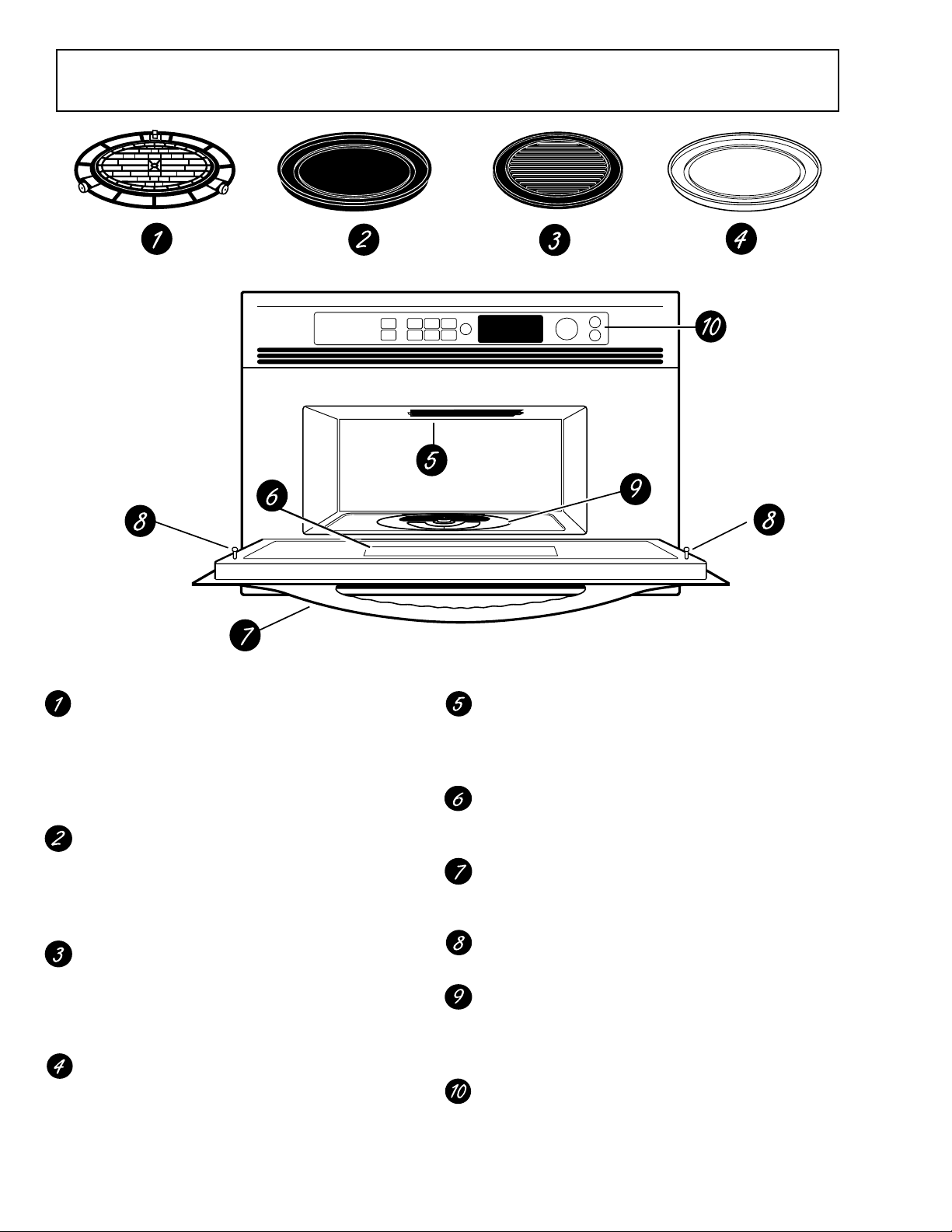
Overview of Advantium
Oven Rack (Turntable)
The oven rack (turntable) must always be in
place, on the oven floor, for all cooking. Be
sure the oven rack (turntable) is seated securely over the square spindle in the center of
the oven.
Black Metal Tray/Baking Sheet
Used during speedcooking only. Put food
directly on the black metal tray and place on
the oven rack (turntable) when using the
speedcook features.
Black Grill Tray/Baking Sheet
Used during speedcooking only. Put food
directly on the black grill tray and place on the
oven rack (turntable) when speedcooking
foods you would normally cook on the grill.
White Ceramic Tray
Used during microwave oven cooking only.
Place on the oven rack (turntable) when using
the microwave features. Place food or
microwave-safe cookware directly on the tray.
Upper Halogen Lamp Assembly
Used during speedcooking only. Two
1500-watt halogen lamps provide heat from
the top of the oven cavity.
Window
Allows cooking to be viewed while keeping
microwaves confined in the oven.
Door Handle
Pull to open the door. The door must be
securely latched for the oven to operate.
Door Latches
Lower Halogen Lamp Assembly
Used during speedcooking only. One
1500-watt halogen lamp provides heat from
the bottom of the oven cavity.
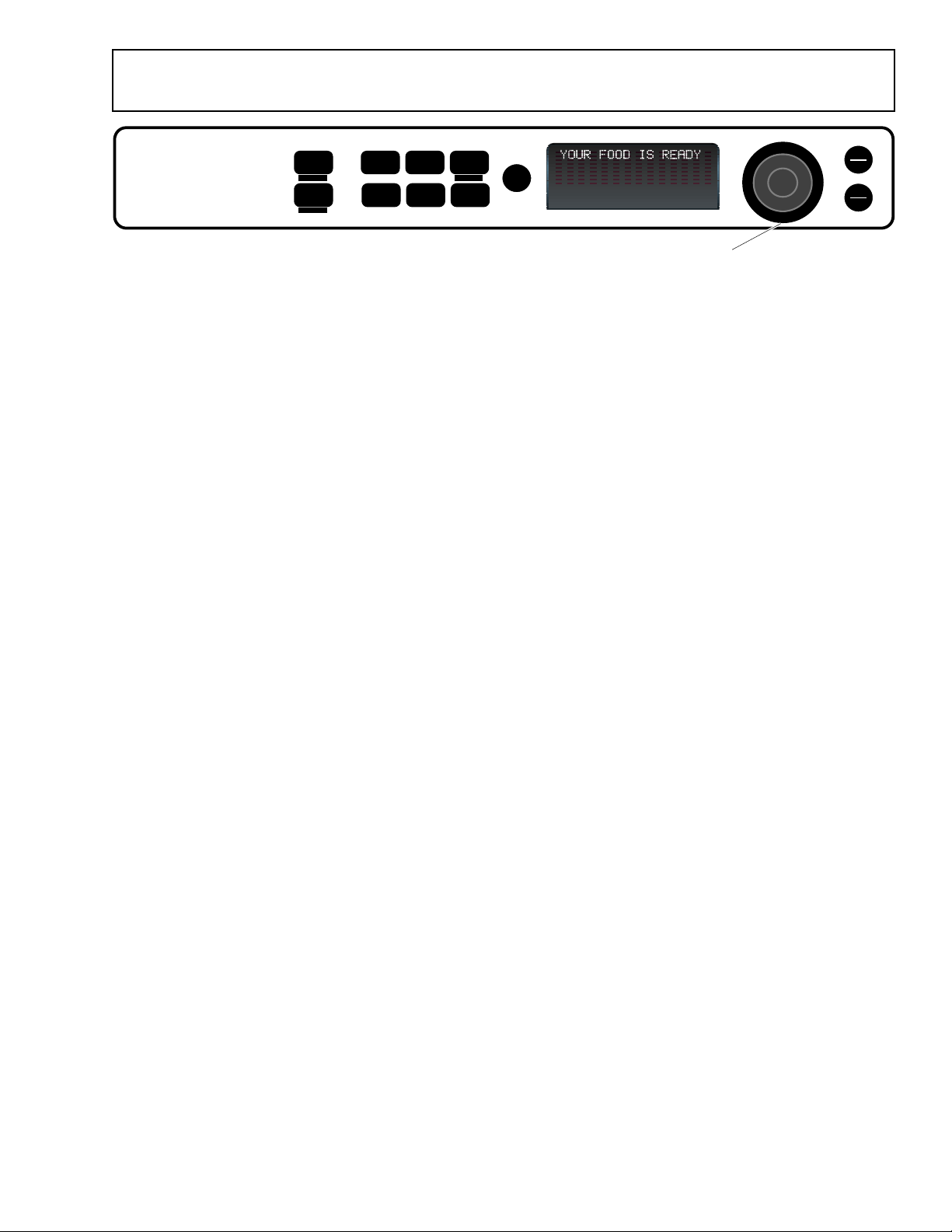
Control Panel
The buttons used to operate the oven are
located on the control panel.
– 12 –
Page 15
SPEED
COOK
REPEAT LAST
MANUAL
COOK
RECIPE
Control Panel Features
POWER
LEVEL
OPTIONS
TIMER
HELP
MICRO
WAVE
OVEN LIGHT
MICRO
EXPRESS
BACK
S
O
E
T
L
E
N
C
R
U
T
P
R
E
S
N
S
E
T
O
START
T
PAUSE
CLEAR
OFF
R
E
T
SPEEDCOOK/REPEA T LAST
Press this button to access the preset speedcook
menu. Press and hold for 3 seconds to repeat the
last cooking selection.
MANUAL COOK/RECIPE
Press this button to set your own speedcook
program.
POWER LEVEL
Press this button and turn/press the selector dial
to change the speedcook upper lamps, lower
lamp, and microwave power level before and
during cooking.
OPTIONS
Press this button to set the Clock and access the
Beeper V olume, Clock Display ON/OFF , Display
Scroll Speed features.
TIMER
Press this button to set the minute timer.
HELP
Press this button to find out more about your
oven’s features.
Selector Dial
GEA00416
MICROWAVE/OVEN LIGHT
Press this button to operate the microwave. Press
while microwave cooking to light the oven cavity.
The light will come on and will remain on until the
end of the cooking cycle.
MICRO EXPRESS
Press for 30 seconds of microwave cooking time.
Each press of the button adds an additional 30
seconds to the remaining cooking time. The oven
starts immediately.
BACK
Press this button to step back one or more levels
in the program process, such as when entering
custom recipes.
SELECTOR DIAL-Turn to select, Press to enter
First turn then press the dial to make food
selections. Also use the dial to increase (turn
clockwise) or decrease (turn counterclockwise)
cooking times.
START/PAUSE
Press this button to start or pause any cooking
function.
CLEAR/OFF
Press this button to cancel all oven programs
except the clock and timer.
– 13 –
Page 16

Notes
– 14 –
Page 17
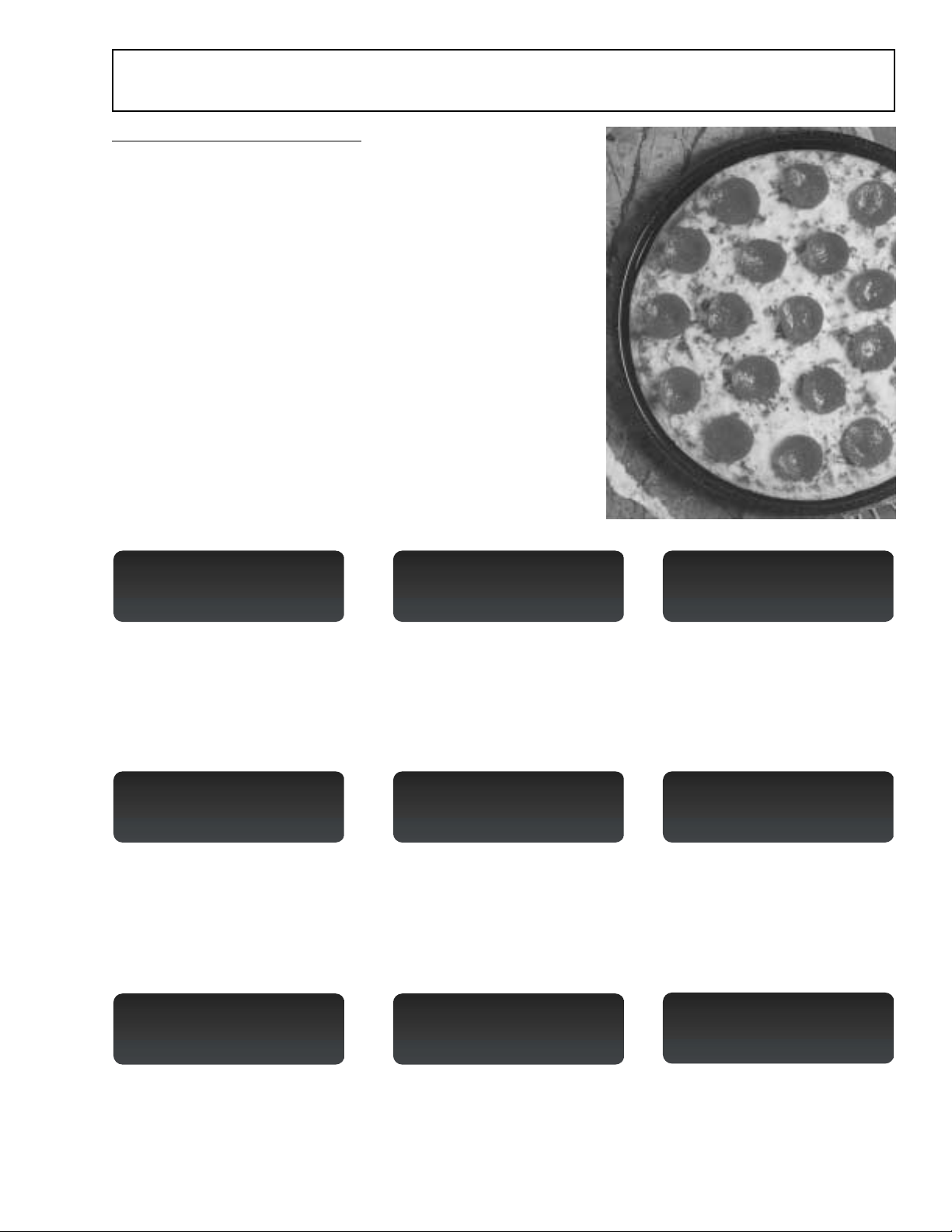
How to Speedcook
To Select a Speedcook Program:
1. Press the SPEEDCOOK button.
2. Turn the selector dial to select the type of food you want.
Press the dial to enter it.
3. Turn the dial to select the specific food. Press the dial to
enter it.
4. Turn the dial to select the amount, size, and/or doneness (if
required, the oven will prompt you). Press the dial after
each selection.
5. Once the display shows “ADJUST TIME OR START,” press
either the selector dial or START/PAUSE button to start
cooking.
If the door is opened during cooking, the oven stops and
“PAUSE” appears in the display. Close the door and press
START/PAUSE to resume cooking. At any time during the
cooking, you can turn the selector dial to change the cooking
time. You can also change power levels.
Press the SPEEDCOOK button to begin:
Select TYPE:
PIZZA
OVEN LOCKED SELECT MUTE TIMER OVEN LOCKED SELECT MUTE TIMER OVEN LOCKED SELECT MUTE TIMER
1. “Select TYPE [of f ood]:”
Turn to “PIZZA” and then press
the selector dial to enter
selection.
Use ROUND METAL TRAY
10:00 U=08 L=07 M=02
OVEN LOCKED SELECT MUTE TIMER OVEN LOCKED SELECT MUTE TIMER OVEN LOCKED SELECT MUTE TIMER
4. After entering the size, you will
see a message instructing you
to “Use R OUND METAL TRAY .”
Be sure to use the metal tray
Select PIZZA type:
REG. CRUST, FROZEN
2. “Select PIZZA type:”
Turn to “REG. CRUST,
FROZEN” and then press the
selector dial to enter selection.
ADJUST TIME or START
10:00 U=08 L=07 M=02
5. “ADJUST TIME or START”
appears. Press the START
button or selector dial to begin
cooking.
Select SIZE:
Regular (12")
3. “Select SIZE:”
Turn to “Regular (12”)” and then
press the selector dial to enter
selection.
REG, CRUST, FROZEN
09:59
6. Once the ov en starts cooking,
you will see your selection in the
display with remaining cooking
time counting down.
GEA00417
GEA00418
GEA00419
that came with the Advantium.
OPTIMIZING COOK TIME
9:55
OVEN LOCKED SELECT MUTE TIMER OVEN LOCKED SELECT MUTE TIMER
7. After approximately 3-5 sec.,
the cook time may be adjusted
up or down to compensate for
variations in line voltage.
CHECK for DONENESS
4:00
8. Minutes before cooking ends,
“CHECK for DONENESS”
appears. Power shuts off until
restarted (ST AR T).
– 15 –
YOUR FOOD IS READY
OVEN LOCKED SELECT MUTE TIMER
GEA00420
9. Minutes later , enjo y pizza with a
crispy brown crust and golden
melted cheese. It doesn’t get
much easier than this.
Page 18

Operating Characteristics
Table of Contents
Power Levels . . . . . . . . . . . . . . . . . . . . . . . . . . . . . . . . . . . . . . . . . . . . . . . . . . . 17
Upper Halogen Lamp Pair. . . . . . . . . . . . . . . . . . . . . . . . . . . . . . . . . . . . . . . 17
Lower Halogen Lamp . . . . . . . . . . . . . . . . . . . . . . . . . . . . . . . . . . . . . . . . . . 17
Microwave Energy . . . . . . . . . . . . . . . . . . . . . . . . . . . . . . . . . . . . . . . . . . . . . 18
Voltage Compensation . . . . . . . . . . . . . . . . . . . . . . . . . . . . . . . . . . . . . . . . . . . 18
Upper Halogen Lamp Balance . . . . . . . . . . . . . . . . . . . . . . . . . . . . . . . . . . . . . 18
Thermal Compensation . . . . . . . . . . . . . . . . . . . . . . . . . . . . . . . . . . . . . . . . . . 19
Thermal Compensation Test. . . . . . . . . . . . . . . . . . . . . . . . . . . . . . . . . . . . . 21
Thermal Protection . . . . . . . . . . . . . . . . . . . . . . . . . . . . . . . . . . . . . . . . . . . . . . 21
Thermal Safety. . . . . . . . . . . . . . . . . . . . . . . . . . . . . . . . . . . . . . . . . . . . . . . . . . 22
Damper Door Assembly . . . . . . . . . . . . . . . . . . . . . . . . . . . . . . . . . . . . . . . . . . 22
Damper Door Switch . . . . . . . . . . . . . . . . . . . . . . . . . . . . . . . . . . . . . . . . . . . 22
Damper Door Open . . . . . . . . . . . . . . . . . . . . . . . . . . . . . . . . . . . . . . . . . . . . 23
Damper Door Closed. . . . . . . . . . . . . . . . . . . . . . . . . . . . . . . . . . . . . . . . . . . 23
Oven Cavity Lamps . . . . . . . . . . . . . . . . . . . . . . . . . . . . . . . . . . . . . . . . . . . . 23
Thermal Fuse . . . . . . . . . . . . . . . . . . . . . . . . . . . . . . . . . . . . . . . . . . . . . . . . . 23
Air Flow . . . . . . . . . . . . . . . . . . . . . . . . . . . . . . . . . . . . . . . . . . . . . . . . . . . . . . . 23
Exhaust Motor . . . . . . . . . . . . . . . . . . . . . . . . . . . . . . . . . . . . . . . . . . . . . . . . 24
Upper and Lower Halogen Blowers . . . . . . . . . . . . . . . . . . . . . . . . . . . . . . . 24
Magnetron Blower Assembly . . . . . . . . . . . . . . . . . . . . . . . . . . . . . . . . . . . . 24
Air Flow Diagram . . . . . . . . . . . . . . . . . . . . . . . . . . . . . . . . . . . . . . . . . . . . . . 25
– 16 –
Page 19
Power Levels
Advantium uses power from high-intensity halogen
lamps, as well as microwave energy, to cook foods
evenly and quickly (average of one-fourth the time
of a conventional oven) to seal in moisture and
flavor.
Example: Upper element set at 80% (U=08),
lower element set at 50% (L=05), and microwave
set at 30% (M=03).
Select UPPER POWER:
5:00 U=08 L=05 M=03
Power levels are selected with the selector dial
and can be adjusted before cooking or during
cooking. When using preset menu foods, the
power levels are already selected for you.
However, power levels can be adjusted when
cooking both preset menu food and when manual
cooking.
Power levels are adjusted independently for the
upper halogen lamps (pair), lower halogen lamp
(single), and microwave energy. When selecting
an upper halogen lamp power level, the power
level can only be selected for the pair. You can not
select power levels for the upper rear and upper
front independently.
Power levels of 0 to 10 can be selected for the
upper halogen lamps (pair), lower halogen lamp,
and microwave energy. The power levels control
the percentage of ON time for the upper halogen
lamp pair, the lower halogen lamp, and microwave
high voltage circuit.
The programming on the smart board which
controls the upper and lower halogen lamps, as
well as the high voltage/magnetron circuits,
operates on a duty cycle of 32 seconds. This
means the power level you select for each
component controls the percentage of ON time
during each 32-second period of time.
In the following example, the upper halogen lamps
would cycle for 80% of each 32-second period, the
lower would cycle at 50% of each 32-second
period, and the microwave high voltage circuit
would be energized for 30% of each 32-second
period.
80%
M=03
L=05
U=08
30%
50%
80%
L=05
M=03
U=08
30%
50%
GEA00421
80%
% ON
TIME
U=08
L=05
M=03
50%
30%
0 32 Secs 64 Secs 96 S
32 Second Duty Cycles
OVEN LOCKED SELECT REM NITE MUTE TIMER
GEA00422
Upper Halogen Lamp Pair (U=)
The upper halogen lamps provide radiant heat to
the top surface of the food. Select a higher setting
for thin foods requiring a golden brown top
(example: fish fillets, toast, boneless chicken
breasts). Select a lower setting for thicker foods
and foods with high sugar or fat content (example:
cakes, roasts).
Upper Halogen
Pair (U=)
Lower Halogen
Lamp (L=)
UPPER AIR GAP
RELAY (RY23)
N L2
UPPER AIR GAP
RELAY (RY22)
UPPER HEATER
RELAY BOARD
UPPER HEATER
RELAY (RY18)
EXTERIOR
RELAY (RY19)
UPPER HEATER
UPPER HEATER
CENTER
1.2
1.2
EXTERIOR
Microwave
(M=)
GEA00423
UHC TCO
ONE SHOT
(293 /32 F)
UHE TCO
ONE SHOT
(293 /32 F)
GEA00396
Lower Halogen Lamp (L=)
The lower halogen lamp provides cooking from
below to heat the cooking surface (cooking trays
and cookware). Select a higher setting for thick or
dense foods that may not cook quickly in the
center (example: casseroles). Select a lower
setting for thin foods (example: cookies) and foods
containing high fat or sugar content (example:
pastries, cakes).
N L1
LOWER HEATER AIR
GAP RELAY (RY21)
RELAY BOARD
LOWER HEATER
RELAY (RY20)
1.2
LOWER
HEATER
LH TCO
ONE SHOT
(293 /32 F)
GEA00397
– 17 –
Page 20
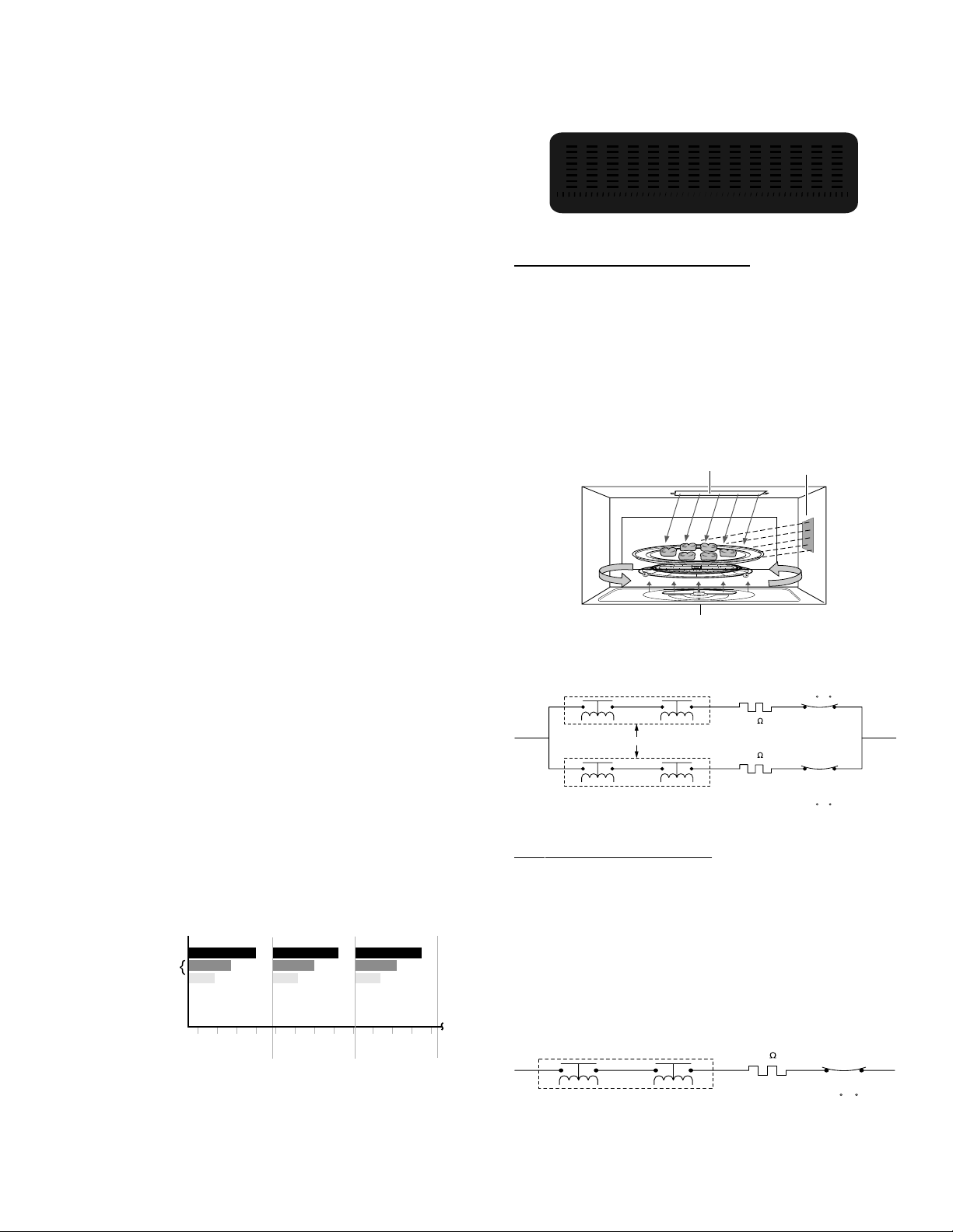
Microwave Energy (M=)
Microwave energy is provided by the high voltage/
magnetron circuit and directed via the wave guide
directly into the oven cavity. As the food rotates on
the oven turntable, microwave energy is evenly
distributed to all portions of the food. Select a
higher setting to shorten cooking time for dense or
heavy foods (example: casseroles, whole
chicken). Select a lower setting for delicate foods
(example: cakes, breads, souffles) or foods
requiring longer cooking times for tender results
(example: stew, pot roast).
CONTROL BOARD
N L1
SECONDARY
INTERLOCK RELAY
HV PRIMARY
WINDING
(MAGNETRON)
PRIMARY
INTERLOCK
FUSE
(20 AMPS)
MGT TCO
(302 /140 F)
CAVITY TCO
ONE SHOT
(302 /140 F)
GEA00398
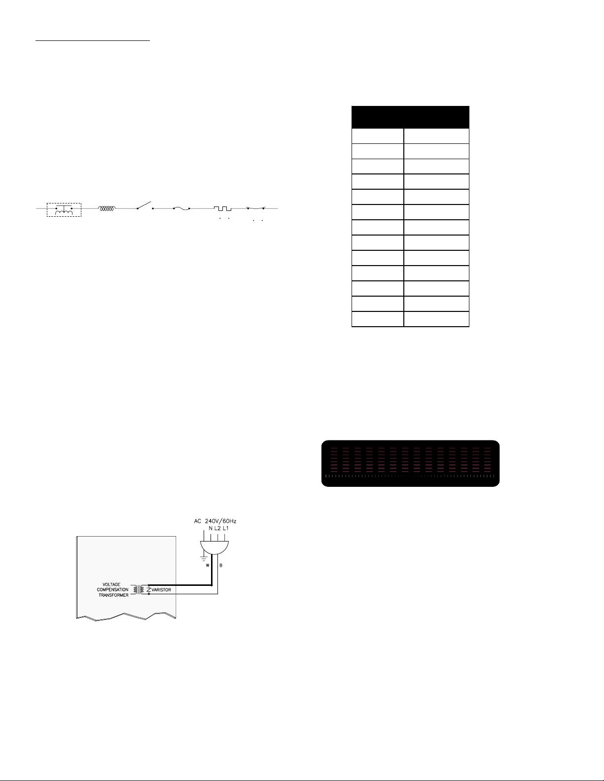
Voltage Compensation
Note: Voltage compensation only occurs during
speedcook operation (preselect menu item). In
other words, when cooking with manual cook,
voltage compensation does not occur. When using
speedcook, you are selecting preselected items
from a menu. These items require compensation
for accurate and consistent cooking results.
Voltage fluctuations in the power lines can cause
inconsistencies in cooking. Advantium
automatically measures line voltage at the start of
each speedcooking selection and adjusts the
cooking time to achieve consistent quality
results.
Line voltage is monitored by the voltage
compensation transformer, which is located on the
smart board. This transformer monitors the
voltage from L2 to neutral.
speedcooking selection that is chosen. The chart
below shows the predicted compensation times
based on a 5-minute speedcook selection (such
as: Biscuits, Refr; Large; 8 biscuits).
VEGATLO
Not2L
8010.06
0119.74
2117.63
4113.62
6117.61
8119.7
0210.0
2211.7-
4213.31-
6218.81-
8213.32-
0311.72-
2310.03-
)sces(EMIT
NOITASNEPMOC
Voltage compensation occurs after approximately
5 seconds of cooking operation. The display will
show “OPTIMIZING COOK TIME.” The time will
flash and then display the new adjusted time,
based on the amount of voltage compensation
required.
OPTIMIZING COOK TIME
9:55
OVEN LOCKED SELECT MUTE TIMER
GEA00425
SMART BOARD
BN
Y
Voltage Compensation Circuit
GEA00424
The optimal line voltage, where no voltage
compensation occurs, is 120 VAC. Above
120 VAC, time is subtracted from the recipe.
Below 120 VAC, time is added to the recipe. The
amount of voltage compensation required is
dependent upon the incoming voltage at the start
of the cooking cycle, and the particular
Voltage compensation only occurs during
speedcook operation and only occurs once during
the cooking cycle (at initial start of speedcook
operation).
Upper Halogen Lamp Balance
As stated previously, the upper halogen lamps
operate together at the same power level.
However, in order to provide even (balanced)
cooking performance, the upper rear halogen
lamp will always cycle at 85% of the upper front
halogen lamp. In other words, if the upper halogen
lamps are set at power level 10 (U=10), you would
expect both elements to operate at 100% of each
32-second duty cycle. Instead, the upper rear
halogen will cycle at 85% of power level 10, or
– 18 –
Page 21

85% of 32 seconds. The upper rear halogen lamp
will cycle off just prior to the upper front.
Thermal Compensation
Note: Thermal compensation only occurs during
speedcook operation (preselect menu item). In
other words, when cooking with manual cook,
thermal compensation does not occur. When
using speedcook, you are selecting preselected
items from a menu. These items require
compensation for accurate and consistent cooking
results.
When cooking several food items consecutively,
the temperature in the oven’s interior can become
very hot. The Advantium speedcooking program
(smart board) automatically compensates for the
increased temperature by adjusting the cooking
power levels of the upper and/or lower halogen
lamps. This innovative technology gives you ovenquality food with consistent results.
resistance changes rapidly with small changes in
temperature. In fact, you can squeeze the
thermistor and see the resistance change fairly
quickly. At room temperature, the thermistor
should read approximately 200K to 250K ohms.
Thermal compensation can affect the upper
halogen lamps power level, the lower halogen
lamp power level, or both the upper and lower
halogen power levels simultaneously. Ther mal
compensation can lower the upper halogen pair
by 1, 2, or 3 power levels. The lower halogen lamp
can also be reduced by 1, 2, or 3 power levels, but
nev er independently of the top halogen lamp pair.
In other words, thermal compensation on the
lower lamp will never be greater than the
compensation occurring on the top lamps. It is
possible, however, to have thermal compensation
occurring on the upper halogen lamp pair, but not
on the lower lamp.
Neither the upper halogen lamp pair nor the lower
halogen lamp can be compensated below power
levels of 2. In other words, if a power level of 3 is
selected for either the upper halogen pair or the
lower halogen lamp, then thermal compensation
can only reduce the power level by a maximum of
1 power level.
GEA00439
Located inside of the oven cavity (upper right rear)
is a thermistor. At the start of each new
speedcooking operation (just prior to voltage
compensation occurring), the cavity thermistor
reads the oven cavity temperature. Depending
upon the oven cavity temperature and the amount
of cooking time selected, the smart board will
adjust the power level of the upper and/or the
lower halogen lamps to compensate for the
additional heat that may already exist in the oven
cavity (if previous cooking occurred).
1
CN6 APPROX. 219 K @ ROOM TEMP.
3
GEA00400
The oven cavity ther mistor has a negative
temperature coefficient. In other words, as the
temperature of the thermistor probe increases, the
resistance of the thermistor decreases. This
– 19 –
Thermal compensation only occurs when oven
cavity temperatures are higher than normal from
the previous cooking operation. When thermal
compensation is required, it will occur immediately
upon the start of a new speedcook operation (just
prior to voltage compensation occurring) and
there will be no indication in the display that
thermal compensation has occurred. The amount
of thermal compensation (1, 2, or 3 power levels)
depends upon the temperature of the oven cavity
at the start of the speedcook operation and the
amount of time selected.
When thermal compensation occurs, it is not
possible to see the adjusted power levels in the
display. If you were to press the power level pad
during a speedcook operation in which thermal
compensation occurred, you would not see the
adjusted power levels in the display. In fact, what
you would see is the original power level setting.
However, you can visually see compensation
occurring by carefully observing the cycling of the
halogen lamps.
WARNING: When viewing the halogen lamps, do
not stare directly into the face of the door window.
View the oven interior from a distance far enough
not to cause eye strain.
Page 22

Notes
– 20 –
Page 23

Thermal Compensation Test
To better understand this operation, you can
perform the following test (only if the oven cavity is
at room temperature). Remove the pan from the
oven so you can see both the upper and lower
halogen lamps. Select “Speedcook, Meats,
Hamburger, 1/2 inch thick, 1-2 patties.” The
following will show in the display:
ADJUST TIME or START
3:00 U=10 L=10 M=10
OVEN LOCKED SELECT MUTE TIMER
GEA00426
Notice that the display shows power levels of 10
for each cooking component. During this test, you
will be operating the oven with no load. For this
reason, it will be necessary to adjust the
microwave power level to zero (M=00). To do
this, press the power level button on the control
panel. Leave the upper and lower power levels at
10 (U=10, L=10), and adjust the microwave to
zero (M=00).
Press START to run
3:00 U=10 L=10 M=00
OVEN LOCKED SELECT MUTE TIMER
NOTE: Set Microwave to Zero (M=00)
GEA00427
What is important to note is that while the power
levels have been reduced (thermal compensation),
the power levels which will show in the display (if
you touch the power level pad while speedcooking
operation is occurring) will be the original power
levels (U=10, L=10, and M=00).
From a consumer’s point of view, if the consumer
were to cook two hamburger patties, and then
immediately cook two more patties, they could
notice the halogen lamps cycling differently with
the same selection used each time. This is
perfectly normal when thermal compensation
occurs. The consumer’s Owner’s Manual states
the following:
Page 21 - Lights
“The halogen lights will dim and cycle on and off
during a speedcook cycle, sometimes even at full
power levels. This is normal. The oven senses the
heat level and adjusts automatically.”
Page 38 - Troubleshooting, Lights
“Light during a speedcook cycle dims and cycles
on and off, even at full power levels. This is normal.
Power level has been automatically reduced
because the oven is hot. The oven senses the
heat level and adjusts automatically.”
Thermal Protection
Start the speedcook operation and carefully notice
the cycling of the halogen lamps. At power levels
of 10, both the upper halogen lamp pair and the
lower halogen lamp should be on 100% of the
time. However, remember that the upper rear
halogen lamp always cycles at 85% of the upper
halogen power level setting, so you will be able to
see the upper rear halogen lamp cycle off briefly
(see “UPPER HALOGEN LAMP BALANCE” for
additional information).
With approximately 1 minute remaining, the oven
will stop and you will be instructed to turn over the
food. Briefly open the door and close it, and then
touch START to resume the remainder of the
cooking time. At the end of the cooking cycle,
repeat the steps above using the same
hamburger selection (remember to once again
set the microwave power level to zero (M=00)).
Once again pay attention to the halogen lamp
cycling. Since the oven is now hot, you should be
able to visually see thermal compensation
occurring. You will notice that both the upper and
lower halogen lamp power levels have been
decreased by some amount.
If oven cavity temperatures reach somewhere in
the range of 500°F to 600°F, or if a speedcooking
selection is chosen which exceeds 12 minutes of
cooking at halogen lamp power levels (upper and
lower) greater than 7, all power levels (upper,
lower, and microwave) will be reduced to 7 for the
remainder of the speedcooking selection. This
system allows for safe exterior operating
temperatures.
In the unlikely event that ther mal protection is
required, the consumer will not notice any change
in the display readout (no power level change
indication); however, they may notice that the
halogen lamps are cycling differently than
expected, due to the change in power levels.
GEA00428
– 21 –
Page 24

As was the case with thermal compensation, the
control is provided by the thermistor and smart
board, with the thermistor sensing the oven cavity
temperature and the smart board providing the
proper responses to lower all power levels to 7.
SMART BOARD
DOOR
SENSING
SWITCH
DAMPER
MOTOR
THERMAL
FUSE
CN6 CN4 CN2
OVEN CAVITY THERMISTOR
AND SMART BOARD
GEA00429
Thermal Safety
In the unlikely event that internal oven cavity
temperatures exceed 600°F, speedcooking
operation will be terminated.
The oven cavity thermistor is constantly sensing
oven cavity temperatures and providing input to
the smart board. When the smart board
determines that over 600°F has been reached, it
will terminate speedcooking operation and return
the oven display to its normal OFF position (with
time-of-day clock showing in the display). When
the unit cools, it will return to normal operation.
Thermal safety provides an additional means of
thermal protection, in addition to the thermal
protection mode mentioned in the previous
section.
GEA00430
During microwave oven cooking, the damper door
is fully open, allowing air to travel through and
around the magnetron tube into the oven cavity.
DAMPER DOOR SHOWN IN OPEN
POSITION ALLOWING AIRFLOW
INTO OVEN CAVITY
DAMPER
DOOR ASSY
GEA00431
During speedcooking operation (recipe or manual
speedcook), the metal damper door rotates into
the damper chamber, closing off air flow from the
magnetron blower into the oven cavity. In doing so,
heat from the oven interior is contained in the
oven cavity.
Damper Door Assembly
The damper door assembly has a metal semiround door, which rotates by control of a damper
motor, to open and close off air from the damper
chamber to the oven cavity. The thermal fuse and
door sensing switch mount to the damper door
assembly.
Damper Door Switch
The damper door sensing switch is mounted to
the damper duct. The switch monitors the metal
door position and provides this information to the
smart board (“Metal damper door open” or “Metal
damper door closed”), which controls the direction
and operation of the damper door motor. If the
damper door sensing switch shorts (or opens), the
damper motor will continually cycle the damper
door open and closed until one complete switch
cycle is detected.
– 22 –
Page 25

Damper Door Open:
Damper Door Open,
Damper Door Closed,
The following illustration shows the position of the
metal damper door in the open position. In this
position, air blowing through and across the
magnetron tube can enter the oven interior. With
the damper door open, the damper door sensing
switch is not depressed.
Damper Door Open,
Damper Door Open,
Sensing Switch Not
Sensing Switch Not
Depressed
Depressed
GEA00440
Damper Door Closed:
The following illustration shows the position of the
metal damper door in the closed position. In this
position, air from the magnetron blower will not
enter the oven interior. With the damper door
closed, the damper door sensing switch is
depressed.
• Speedcooking - At the start of speedcooking
operation, the damper door will close, sealing
off the damper duct from the oven cavity. The
damper door will remain in the closed position
during the entire speedcook operation,
depressing the damper door sensing switch.
• Microwave oven cooking - At the start of
microwave cooking, the damper door will cycle
one complete revolution (completely close and
then reopen) and stop in the open position
(damper door sensing switch not depressed).
The oven cavity lamps will not illuminate
during microwave operation.
Oven Cavity Lamps
The oven cavity lamps are located at the upper
rear of the oven cavity and illuminate only when
the oven door is opened. During microwave oven
cooking, the oven interior can be illuminated by
pressing the MICROWAVE OVEN LIGHT pad on
the front panel. The lights will come ON and will
remain ON until the end of the cooking cycle. In
the event that it becomes necessary to change the
lamps, it will be necessary to remove the oven
from its installation.
Thermal Fuse
The thermal fuse is mounted to the top of the
damper duct over a small rectangular hole in the
duct. This hole allows the thermal fuse to sense
temperatures inside the duct cavity. The fuse is
secured to the damper duct with a small screw
and retainer. In the event that it becomes
necessary to change this fuse, it will be necessary
to remove the oven from its installation (see page
32).
Damper Door Closed,
Damper Door Closed,
Sensing Switch Depressed
Sensing Switch Depressed
GEA00441
The following damper door positions will occur
with various operations:
• When the oven is not in use (power applied
to the unit with time-of-day clock showing), the
damper door will always be in the open
position.
Air Flow
There are four fan motors in the Advantium design
which provide airflow for proper cooling. During
speedcooking (pre-selected recipe or manual
speedcook), all four fan motors will run during
the entire speedcook operation.
– 23 –
Page 26

LOWER HALOGEN
BLOWER
EXHAUST VENT
MOTOR
UPPER HALOGEN
BLOWER
MAGNETRON BLOWER
ASSEMBLY
GEA00432
Exhaust Motor
The exhaust motor helps remove heat from all
components. The fan will be ON during cooking. At
the end of speedcooking, the exhaust fan will
continue to run for 1 minute (30 seconds on HIGH
and 30 seconds on LOW), and the display will
read “OVEN IS COOLING.” The fan will
automatically shut off when the internal par ts of
the oven have cooled.
Upper and Lower Halogen Blowers
The upper and lower halogen blowers only run
during speedcook operations (speedcook recipe
or manual speedcook selections). Both motors
pull in fresh air from outside the unit and direct the
air across the halogen lamps.
Upper Halogen Blower
As you will note from the illustration on the
following page, the upper halogen blower pulls air
in from the upper grille area. The air is then
directed (blown) across the upper halogen lamp
pair and exhausted back into the room through the
lower grille area. The hot air directed across the
upper halogen lamp pair is not controlled or
directed by the exhaust motor.
Lower Halogen Blower
The lower halogen blower draws room air in
through the upper grille area. The air is pulled
down into the lower halogen blower and directed
(blown) across the lower halogen lamp. The air is
then exhausted through the lower grille area.
Magnetron Blower Assembly
During microwave operation, room air is drawn in
through the upper grille area and into the
magnetron blower area. The magnetron fan blows
the cool air through and around the magnetron
tube. The air then passes through the damper
door assembly (damper door is open during
microwave operation) into the oven cavity.
HIGH
LOW
As air enters the oven cavity, pressure builds up
inside, forcing hot air out the top of the oven. The
air passes across the humidity sensor and back
into the room through the lower grille area.
GEA00433
– 24 –
Page 27

GEA00570
EXHAUST POWER AIR FLOW
UPPER HALOGEN BLOWER AIR FLOW
LOWER HALOGEN BLOWER AIR FLOW
MAGNETRON FAN AIR FLOW
Air Flow Diagram
– 25 –
Page 28

Mechanical Disassembly
Table of Contents
Serviceability With Oven Installed. . . . . . . . . . . . . . . . . . . . . . . . . . . . . . . . . . . . . 27
Remove Oven Door . . . . . . . . . . . . . . . . . . . . . . . . . . . . . . . . . . . . . . . . . . . . . . . 27
Disassemble Oven Door . . . . . . . . . . . . . . . . . . . . . . . . . . . . . . . . . . . . . . . . . . . 27
Serviceability With Oven Removed . . . . . . . . . . . . . . . . . . . . . . . . . . . . . . . . . . . . 27
Remove Oven From Cabinet or Wall Opening . . . . . . . . . . . . . . . . . . . . . . . . . 27
Remove Oven Cavity Lamps . . . . . . . . . . . . . . . . . . . . . . . . . . . . . . . . . . . . . . . 28
Remove Outer Access Covers. . . . . . . . . . . . . . . . . . . . . . . . . . . . . . . . . . . . . . 28
Interlocks and Monitor . . . . . . . . . . . . . . . . . . . . . . . . . . . . . . . . . . . . . . . . . . . . 29
Remove and Adjust Door Latches. . . . . . . . . . . . . . . . . . . . . . . . . . . . . . . . . . . 30
Access and Remove Control Panel . . . . . . . . . . . . . . . . . . . . . . . . . . . . . . . . . . 30
Remove Relay Board . . . . . . . . . . . . . . . . . . . . . . . . . . . . . . . . . . . . . . . . . . . . . 31
Remove Low Voltage Transformer . . . . . . . . . . . . . . . . . . . . . . . . . . . . . . . . . . 31
Remove Main PCB Assembly. . . . . . . . . . . . . . . . . . . . . . . . . . . . . . . . . . . . . . . 32
Remove Upper Exhaust Assembly - Left . . . . . . . . . . . . . . . . . . . . . . . . . . . . . 32
Remove Damper Door Assembly. . . . . . . . . . . . . . . . . . . . . . . . . . . . . . . . . . . . 32
Remove Upper Blower Motor Assembly. . . . . . . . . . . . . . . . . . . . . . . . . . . . . . 33
Remove Oven Cavity Thermistor. . . . . . . . . . . . . . . . . . . . . . . . . . . . . . . . . . . . 33
Remove Upper Air Tunnel Assembly. . . . . . . . . . . . . . . . . . . . . . . . . . . . . . . . . 34
Remove Upper Halogen Assembly . . . . . . . . . . . . . . . . . . . . . . . . . . . . . . . . . . 34
Microwave High-Voltage Section. . . . . . . . . . . . . . . . . . . . . . . . . . . . . . . . . . . . 36
Remove HV Capacitor and Diode . . . . . . . . . . . . . . . . . . . . . . . . . . . . . . . . 36
Remove Magnetron Fan Motor Assembly. . . . . . . . . . . . . . . . . . . . . . . . . . 36
Remove Magnetron Assembly . . . . . . . . . . . . . . . . . . . . . . . . . . . . . . . . . . . 37
Remove High Voltage Transformer . . . . . . . . . . . . . . . . . . . . . . . . . . . . . . . 37
Remove Lower Blower Motor Assembly. . . . . . . . . . . . . . . . . . . . . . . . . . . . . . 38
Remove Turntable Motor . . . . . . . . . . . . . . . . . . . . . . . . . . . . . . . . . . . . . . . . . . 38
Remove Lower Halogen Lamp. . . . . . . . . . . . . . . . . . . . . . . . . . . . . . . . . . . . . . 38
– 26 –
Page 29

Serviceability With Oven Installed
The following component can be accessed from
the front of the oven with the unit installed:
• Oven door
Remove Oven Door
WARNING: A microwave leakage test must be
performed anytime a door is removed, replaced,
disassembled, or adjusted for any reason. The
maximum leakage is 4 MW/CM
“Microwave Leakage Test” on page 44).
1. Disconnect power by turning off the circuit
breaker.
2. Open the door and remove any ceramic or
metal trays or grills from the oven.
Caution: Put electrician’s tape on each side of the
hinges prior to performing the next step. This will
protect the door panel from scratches.
2
(refer to
3. To remove the door handle, remove 2 screws
and 2 E-rings from the holder handle.
4. To remove the glass mount, remove 6 screws
from the bottom of the door frame.
5. To remove hinge assemblies, remove 6 screws
from the door frame.
3. Insert a 1.0-in.-long pin (0.098-in. diameter)
into the hole of each hinge.
4. Close the door approximately one-third of the
way.
5. Lift up on the door to remove it from the oven.
GEA00345
GEA00352
Serviceability With Oven Removed
WARNING: Before proceeding, remove all power
to the oven by tur ning off the appropriate circuit
breaker.
WARNING: When reassembling the product,
remember to reattach all ground wires and put
screws in their correct locations.
The oven must be removed from the
installation to allow servicing of internal
components.
Remove Oven From Cabinet or
Wall Opening
Disassemble Oven Door
1. Remove the door from the oven (see previous
procedure).
2. Remove 4 screws from the upper side of the
door frame. This will separate the door glass.
WARNING: This oven requires 2 people f or the
removal process. Grasp the bottom of the oven at
the front and rear on each side.
Caution: Do not use the oven handle to lift or
lower the oven. Damage will occur!
• Be careful that the conduit is not caught or
stressed during removal.
– 27 –
Page 30

1. Remove 4 mounting screws located in the
front oven frame.
2. Remove 2 screws holding the lamp housing in
place.
ScrewsScrews
GEA00442
3. Slide the housing out from under the tabs.
TabsTabs
GEA00342
2. Slide the oven forward, out of the cabinet or
wall opening.
3. Lower the oven onto a protected surface for
further ser vicing.
Remove Oven Cavity Lamps
1. Remove the access panel at the rear of the
unit.
GEA00443
4. Rotate the lamp housing to replace the bulb
(WB36X10160).
Remove Outer Access Covers
To access all other electrical components
(excluding the left latch switch), one or more
covers must be removed.
WARNING: Before removing covers, remove all
power to the oven by turning off the appropriate
circuit breaker.
To Remove the Top Access Cover:
1. Remove 9 screws and lift off the cover.
To Remove the Right Access Cover:
1. Remove the top access cover (see previous
procedure).
2. Remove 8 screws on the right access cover
panel.
3. Lift off the cover.
– 28 –
Page 31

To Remove the Left Access Covers:
GEA00341
1. Remove the top access cover (see previous
procedure).
2. Remove 8 screws from the left access cover
and lift off the cover.
To Remove the Rear Access Cover:
1. Remove the top, right, and left access covers
(see previous procedures).
2. Remove 6 screws from the rear access cover.
3. Lift off cover.
To Remove the Lower Front Grille:
1. Remove 3 screws under the grille from the
bottom access panel.
2. Place fingers on each side of the grille.
3. Pull grille forward and upward to disengage
hinge tabs from the chassis.
To Remove the Bottom Access Cover:
1. Remove the lower screws from the right
access panel (5 screws) and rear access
panel (1 screw).
2. Remove the left access panels and lower front
grille (see previous procedures).
3. Remove 7 screws from the bottom access
panel.
4. Lift cover slightly to disengage tabs from oven
chassis.
5. Remove bottom access cover.
Interlocks and Monitor
The primary, door sensing (right and left), and
monitor switches are mounted to plastic latch
boards on the right and left sides of the oven
cavity.
Note: To access the 3 switches in the left latch
assembly, remove 1 screw from the door switch
access cover on the left access panel. Remove
the access cover.
Primary Interlock Test
1. Disconnect the power, remove the enclosure,
and discharge the capacitor.
2. Check the continuity of the switch:
• Door closed: 0 ohms
• Door open: infinite ohms
Door Sensing Test
Make continuity check betw een switch terminals.
Normal readings are:
• Door closed: 0 ohms
• Door open: infinite ohms
Monitor Switch
The bottom latch pawl pushes horizontally and
actuates the lever of the monitor interlock,
opening the switch.
• Door closed: infinite ohms
• Door open: 0 ohms
Interlock System Test
1. Disconnect the power, remove the enclosure,
and discharge the capacitor.
2. Check the 20-amp fuse for continuity and
proper size. Do not use any other fuse or size
except 20 amp.
3. Remove the monitor switch leads to isolate the
switch.
4. Check continuity of the monitor switch with the
door open and door closed.
• Door closed: infinite ohms
• Door open: 0 ohms
– 29 –
Page 32

5. Test the circuit operation.
Adjustment
Alignment Peg
To Adjust the Left Latch Assembly:
a. Connect temporary jumper leads across
relay contacts, and primary interlock and
door sensing switches to simulate shorted
switch contacts. Locate convenient
connections in the circuit to be certain
COM and NO terminals are used.
b. Connect the ohmmeter (Rx1) across the
line terminals of the power cord. Continuity
must show:
• Door closed: low ohms
• Door open: 0 ohms
c. Remove the 20-amp fuse. The circuit must
open (infinite ohms). If the circuit does not
open, check wiring of monitor and interlock
circuits.
WARNING: After completing the test, remove the
temporary jumper leads from the interlocks and
relay, and reconnect the monitor switch leads.
Remove and Adjust Door Latches
1. Remove the door switch access cover on the
left access panel.
2. Adjust the screws or replace the door switches
as needed.
3. Retighten screws.
Latch
Latch
Adjust
Adjust
Slots
Slots
Latch
Latch
Switch
Switch
GEA00455
Access and Remove Control Panel
Caution: Perform the microwave leakage test
when replacing or adjusting interlock switches or a
latch board.
To Adjust the Right Latch Assembly:
1. Remove the top and right access covers (see
page 28).
2. Adjust the screws or replace the door switch
as needed.
3. Retighten screws.
Latch SwitchLatch Switch
Adjustment
Adjustment
Screws
Screws
The control panel is hinged at the bottom and
secured at the top with holes that fit over
alignment pegs on the oven trim.
To Access the Control Panel:
1. Open the oven door and place your thumbs
under each end of the control panel.
2. Push upward to disengage the holes from the
alignment pegs.
3. Allow the top of the control panel to fall
forward.
Alignment Peg
Alignment Peg
(1 on Each Side)
(1 on Each Side)
GEA00454
– 30 –
Lower Hinge
Lower Hinge
(1 on Each Side)
(1 on Each Side)
GEA00445
Page 33

To Remove the Control Panel:
Caution: Be sure to note the location and routing
of wires for proper reinstallation purposes.
1. Remove the top access cover (see page 28).
2. Disconnect all associated connector plugs.
3. Lift the control panel to disengage the lower
hinge tabs from the chassis.
4. Remove the control panel.
LED
LED
Display
Display
Note: The fuse is located on the right side of the
relay board housing.
FuseFuse
GEA00448
Remove Low Voltage Transformer
1. Remove the top and rear access covers (see
pages 28-29).
Control
Control
Assembly
Assembly
PCB LED
PCB LED
Display
Display
Selector
Selector
PCB
PCB
GEA00446
Remove Relay Board
1. Remove the top access cover (see page 28).
2. Remove 1 screw that secures the relay board
to the metal frame.
ScrewScrew
GEA00447
3. Disconnect all associated wiring to relay
board.
4. Lift the relay board and disengage the hinges
at the bottom of the board.
5. Remove the relay board.
2. Remove 1 screw on the front tab of the low
voltage transformer beside the main PCB
assembly.
3. Slide the transformer forward to disengage the
back tab from the molded holder on the
chassis.
Remove
P
R
I
M
A
R
Y
Remove
Screw
Screw
GEA00449
WHITE
22
BLACK
N
L1
GEA00399
CN11
SlideSlide
1.4
5.5
1.9
RED
RED
WHITE
BLACK
YELLOW
S
5
E
C
O
N
D
A
4.1
R
1
Y
CN11
1
CN1
3
– 31 –
Pins 4 to 5 .....1.4 ohms....... 7.7 VAC
Pins 1 to 3 .....4.1 ohms....... 6.6 VAC
Pins 1 to 2 .....1.9 ohms....... 12.4 VAC
Pins 2 to 3 .....5.5 ohms....... 19.0 VAC
Page 34

Remove Main PCB Assembly
Remove Upper Exhaust Assembly - Left
1. Remove the top and rear access covers (see
pages 28-29).
2. Remove 4 screws that attach the main PCB
assembly to the plastic support.
3. Slide the board forward and lift it slightly
upward to disengage the board from 4 rear
tabs.
TabsTabs
ScrewsScrews
Rear TabsRear Tabs
1. Remove the top, left, and rear access covers
(see pages 28-29).
2. Remove 3 screws and disconnect the harness.
Harness
Harness
Disconnect
Disconnect
ScrewsScrews
GEA00452
3. Lift exhaust motor upward to remove.
Note: The fan capacitor is located to the right of
the exhaust motor.
TabsTabs
GEA00450
4. Remove 2 screws on the front and 1 screw on
the back of the plastic support. Slide the
support to the left.
TabsTabs
ScrewsScrews
Fan CapacitorFan Capacitor
GEA00453
Remove Damper Door Assembly
1. Remove the top and right access covers (see
page 28).
GEA00451
– 32 –
Page 35

2. Remove 1 screw for more flexibility when
accessing the damper door assembly and
oven cavity thermistor.
ScrewScrew
GEA00576
Thermal Fuse
Thermal Fuse
Cover Plate
Cover Plate
Thermal Fuse
Thermal Fuse
GEA00469
3. Remove 2 screws via the damper screw
access holes.
ScrewsScrews
GEA00575
Damper Screw
Damper Screw
Access Ports
Access Ports
5. Move the fan motor assembly out of the way.
6. Remove 2 screws securing the damper door
assembly.
7. Remove the assembly.
Remove Upper Blower Motor Assembly
1. Remove the top and right access covers (see
page 28).
2. Remove the damper door assembly (see
previous procedure).
3. When the damper housing is removed,
remove 3 screws by the upper blower motor.
Screws
Screws
GEA00574
4. To change the thermal fuse, remove 1 screw
from the thermal fuse cover plate.
GEA00463
4. Remove the motor.
Remove Oven Cavity Thermistor
1. Remove the top and right access covers (see
page 28).
2. Remove the damper door assembly (see page
32), HV capacitor and diode (see page 36),
magnetron fan motor assembly (see page 36),
and magnetron (see page 37).
– 33 –
Page 36

3. With the magnetron removed, you can now
Thermistor
see the thermistor, located under the air
tunnel.
Thermistor
Thermistor
Remove Upper Air Tunnel Assembly
Upper Air
Tunnel Assembly
GEA00579
4. Remove 2 screws holding the thermistor in
place. Access the screws through the access
ports.
Note: Plug buttons sit on the access ports.
Remember to insert them when reinstalling the
thermistor.
Screw Access PortsScrew Access Ports
GEA00578
EXHAUST POWER AIR FLOW
UPPER HALOGEN BLOWER AIR FLOW
LOWER HALOGEN BLOWER AIR FLOW
MAGNETRON FAN AIR FLOW
Lower Air
Tunnel Assembly
GEA00585
1. Remove all access covers (see pages 28-29).
2. Remove the exhaust motor, PCB assembly,
and upper barrier (see page 32).
3. Remove 4 screws from upper air tunnel
assembly.
4. Carefully lift assembly up from the chassis to
remove.
5. Push up on the thermistor from inside the
oven cavity and remove.
GEA00439
6. Disconnect the thermistor plug.
Remove Upper Halogen Assembly
1. Remove all access covers (see pages 28-29).
2. Unplug the wiring harness from the following
components:
• Left latch switches
• Oven cavity T.C.O. (upper left rear of unit)
• Exhaust fan assembly
• All connections to the main PCB except the
LVT
• Upper halogen lamps and oven cavity lamps
• Fuse
• Relay board
• Upper blower fan assembly
3. Remove the exhaust fan assembly and fan
capacitor support.
– 34 –
Page 37

4. Remove the main PCB.
8. Remove the control panel (see page 31).
5. Remove the relay board and mounting.
6. Remove 6 air cover screws.
ScrewsScrews
9. Remove the oven cavity lamp assembly (see
page 28).
10. Disconnect 4 wire leads from the upper
thermostat.
Upper Halogen T.C.O.sUpper Halogen T.C.O.s
GEA00457
GEA00460
11. Straighten 8 tabs that secure the reflector to
the halogen cover.
12. Carefully lift the cover off the lamps.
ScrewsScrews
7. Remove 4 screws from the lamp cover.
Halogen Lamp
Halogen Lamp
Housing Screws
Housing Screws
GEA00458
GEA00459
Caution: Do not touch the halogen lamps. Dirt
and skin oil can cause the lamps to explode
when turned on.
Note: The two upper halogen lamps are replaced
as a pair.
GEA00461
– 35 –
Page 38

Microwave High-Voltage Section
Remove Magnetron Fan Motor Assembly
WARNING: Prior to servicing the high-voltage
capacitor or diode, remove power to the oven
(turn off the circuit breaker).
WARNING: Always be certain the capacitor is
discharged before servicing. Manually discharge
by placing an insulated-handle screwdriver
between the diode connection of the capacitor
and the oven chassis ground. Use screw head
close to capacitor to ensure ground metal contact.
The microwave high-voltage section is located on
the right side of the Advantium oven. To access,
remove the top and right access covers (see page
28).
Capacitor
High Voltage
High Voltage
Transformer
Transformer
Capacitor
Note: The electrical terminal ends which attach to
the high-voltage capacitor have locking tabs on
them. These tabs cannot be seen because they
are encased in plastic. To remove these terminals,
grasp the top and bottom of the terminal with
needle-nose plier jaws. Gently squeeze the plier
jaws together while pulling the electrical terminal
from the capacitor.
DEPRESS LOCKING TAB
NOTE: TERMINAL END IS ENCASED IN CLEAR RUBBER
AND DOES NOT ALLOW YOU TO SEE LOCKING
TAB
GEA00434
1. Disconnect the red and white high-voltage
transformer leads from the capacitor.
2. Remove the top screw from the fan motor
assembly.
Diode
Diode
GEA00571
Remove HV Capacitor and Diode
1. Disconnect all associated connector plugs.
2. Remove 1 screw connecting the diode to the
oven chassis.
3. Remove 1 screw connecting the capacitor
mounting bracket to the plastic holder.
Chassis
Chassis
Screw
Screw
Diode
Diode
Screw
Screw
GEA00467
Top ScrewTop Screw
Magnetron
Magnetron
T.C.O.
T.C.O.
GEA00464
3. Remove 1 screw connecting the diode to the
oven chassis.
4. Remove the capacitor, diode, and capacitor
mounting bracket as one assembly.
Diode
Diode
Screw
Screw
4. Pull the assembly toward you and tip it slightly
back to remove the assembly from the oven.
– 36 –
GEA00465
Page 39

Remove Magnetron Assembly
1. With the top and right access covers removed,
remove the HV capacitor, diode, magnetron
fan (see page 36); and the damper housing
(see page 32).
2. Disconnect all associated connector plugs.
3. Remove 4 screws securing the magnetron
assembly to the oven chassis and remove the
magnetron assembly.
ScrewsScrews
4. Remove the magnetron thermal cut-out
(T.C.O.).
Remove High-Voltage Transformer
1. Disconnect 6 wiring connector plugs.
2. Remove 4 screws that secure the high-voltage
transformer to the lower blower motor
assembly.
3. Remove the high-voltage transformer.
GEA00577
– 37 –
GEA00522
Page 40

Remove Lower Blower Motor Assembly
4. Disconnect all associated connector plugs.
Note: The magnetron fan motor, HV capacitor,
and diode must be removed before you can
access the lower blower motor assembly.
5. Lift fan motor assembly upward while
removing the lower blower motor assembly
from the chassis.
Remove T urntable Motor
1. Remove the turntable.
2. On the bottom access cover, remove 1 screw
from the base plate cover. Remove the cover
by rotating it counterclockwise.
1. Remove the top and right access covers (see
page 28).
2. Remove 4 screws securing the magnetron
blower to the oven chassis (see page 37).
3. Remove 4 screws securing the lower blower
motor in place.
GEA00370
3. Disconnect motor leads.
4. Remove 2 screws securing the turntable motor
to the oven cavity assembly.
GEA00347
Remove Lower Halogen Lamp
1. Remove the turntable.
2. Remove 3 screws from the lower right access
panel, and 1 screw from the lower corner of
the rear access panel.
ScrewsScrews
3. Remove the left and bottom access covers
(see page 29).
4. Disconnect wiring to the lower halogen lamp
(white connector).
GEA00580
– 38 –
Page 41

5. Remove 2 screws from the lower edge of the
inside left panel.
6. Remove 1 screw from the small right barrier
and remove the barrier.
7. Remove 1 screw from the large right barrier,
straighten the mounting tabs, and remove the
barrier.
8. Remove 4 screws from the lower air tunnel
assembly.
9. Lower the air tunnel and ease it out from
under the inside left panel.
10. Disconnect the leads to the lower halogen
lamp T.C.O.
11. Remove the halogen lamp.
GEA00350
– 39 –
Page 42

Notes
– 40 –
Page 43

Troubleshooting
Table of Contents
Diagnosing Cooking Problems . . . . . . . . . . . . . . . . . . . . . . . . . . . . . . . . . . . . 42
Food Items Appear to be Undercooked . . . . . . . . . . . . . . . . . . . . . . . . . . . 42
Food Items Appear to be Overcooked or Burned . . . . . . . . . . . . . . . . . . . 42
Diagnosing a “Dead” Unit . . . . . . . . . . . . . . . . . . . . . . . . . . . . . . . . . . . . . . . . 43
Microwave Performance Test. . . . . . . . . . . . . . . . . . . . . . . . . . . . . . . . . . . . . . 44
Humidity Sensor Test . . . . . . . . . . . . . . . . . . . . . . . . . . . . . . . . . . . . . . . . . . . . 44
Microwave Leakage Test . . . . . . . . . . . . . . . . . . . . . . . . . . . . . . . . . . . . . . . . . 44
Performance Test for Halogen Lamps . . . . . . . . . . . . . . . . . . . . . . . . . . . . . . 45
Key Panel Test . . . . . . . . . . . . . . . . . . . . . . . . . . . . . . . . . . . . . . . . . . . . . . . . . . 45
Fault Codes . . . . . . . . . . . . . . . . . . . . . . . . . . . . . . . . . . . . . . . . . . . . . . . . . . . . 45
– 41 –
Page 44

Diagnosing Cooking Problems
An important part of diagnosing any consumer
cooking concern is listening carefully to the
consumer describe the problem. Equally important
is asking the consumer the right questions. The
following diagnostic information is intended as a
guide for you to follow when addressing cooking
concerns.
Food Items Appear to be Undercooked
Foods which appear to be undercooked or
partially cooked can be the result of any one of the
following items. The possible causes listed below
are sorted from most likely to least likely, with item
#1 being the first item that you should check.
1. Is the consumer selecting the correct type of
cooking (microwave vs. speedcook), and/or is
the consumer using the correct time and
power levels for the type, size, and quantity of
food being cooked (see the Advantium cooking
guide)?
2. Is the consumer using the correct cookware
for the type of food being cooked (see pages
5 and 17 of the Owner’s Manual, and pages 5
and 6 of the Advantium cookbook)?
3. Is the consumer arranging the food properly
on the metal cooking trays (see the Advantium
cooking guide and page 7 of the cookbook)?
4. Is the turntable operating properly so that
microwave energy and halogen heat are being
evenly distributed to the food?
5. Inspect the upper and lower halogen lamp
covers to ensure that they are free of grease
and food spatterings. Build-ups of grease and
food spatterings can cause a decrease in
cooking performance.
6. Confirm proper line voltage to the unit (check
voltage under full load).
7. Confirm that voltage compensation is
operating properly (see page 18 of this service
guide for details and diagnostic information).
8. Confirm that the upper and lower halogen
lamps are operating (illuminating).
9. Check upper and lower halogen lamp
operation at power level 10 and again at power
level 5 to be sure that lamps are cycling
properly. At this point, you must have a
thorough understanding of power level
operation, upper halogen lamp balance
operation, and thermal compensation (see
pages 17-21 of this service guide for detailed
information).
10. Perform a microwave performance test (page
44) to confirm that microwave energy output
(HV/magnetron circuit) is operating to
specification.
11. Are all fan motors operating properly (page 23
of this service guide)? During speedcook
operation, all fan motors must operate
(exhaust fan, upper halogen lamp blower,
lower halogen lamp blower, and magnetron
blower). Improper airflow can cause the
halogen lamps or magnetron tube to cycle on
the thermal cut-outs (T.C.O.s).
Food Items Appear to be Overcooked or Burned
Foods which appear to be overcooked or burned
can be the result of any one of the following items.
The possible causes listed below are sorted from
most likely to least likely, with item #1 being the
first item that you should check.
1. Is the consumer selecting the correct type of
cooking (microwave vs. speedcook), and/or is
the consumer using the correct time and
power levels for the type, size, and quantity of
food being cooked (see the Advantium
cooking guide)?
2. Is the consumer using the correct cookware
for the type of food being cooked (see pages
5 and 17 of the Owner’s Manual, and pages 5
and 6 of the Advantium cookbook)?
3. Is the consumer arranging the food properly
on the metal cooking trays (see the Advantium
cooking guide and page 7 of the cookbook)?
4. Is the turntable operating properly so that
microwave energy and halogen heat are being
evenly distributed to the food?
5. Confirm proper line voltage to the unit (check
voltage under full load).
6. Confirm that voltage compensation is
operating properly (see page 18 of this service
guide for details and diagnostic information).
– 42 –
Page 45

7. Check upper and lower halogen lamp
operation at power level 10 and again at
power level 5 to be sure that lamps are cycling
properly. At this point, you must have a
thorough understanding of power level
operation, upper halogen lamp balance
operation, and thermal compensation (see
pages 17-21 of this service guide for detailed
information).
8. Confirm that thermal compensation is
operating properly by following the thermal
compensation test (see page 21 of this
service guide).
Diagnosing a “Dead” Unit
A “dead” unit is better defined as a unit that
appears to have no power to it (no clock display,
oven cavity lamp, or key panel responses). The
following components and associated wiring
should be checked in the below order when
diagnosing a “dead” unit.
L1L2N
R
W
CAVITY T.C.O
ONE SHOT
(150/0 C)
(302/32 F)
M.G.T T.C.O
(150/60 C)
(302/140 F)
FUSE(20A)
THERMAL FUSE
ONE SHOT
(195 C)
(383 F)
R
Y
B/B
B
R/B
RR
GEA00435
SMART
BOARD
CN11
CN1
W
VARISTOR
B
R
AC 240V/60Hz
L.V.T
22.0
3. If you read approximately 22 ohms from L1 to
NEUTRAL, suspect a defective smart board,
loose wiring connection, or open secondary
winding of the low voltage transfor mer.
1. At the power source, use your volt/ohmmeter
and check the resistance from L1 to
NEUTRAL. The resistance should be
approximately 22.0 ohms. Note: The
resistance reading that you just made is
shown in the schematic diagram at the upper
right corner of this page (low voltage
transformer primary resistance).
GEA00517
2. If you do not read continuity from L1 to
NEUTRAL, suspect the following:
• Open fuse
• Open cavity T.C.O.
• Low voltage transformer (open primary
winding)
• Open magnetron tube T.C.O.
• Open thermal fuse
• Defective smart board
Also, check all associated wiring and wiring
connections.
GEA00436
– 43 –
Page 46

Microwave Performance Test
This test will verify that the microwave oven high
voltage and magnetron circuits are operating to
performance specifications.
1. Using only a WB64XO073 beaker, place a
standard test load of 1 liter (1000 ml) of water
in the beaker. Measure and record the water
temperature prior to making the test. The
water temperature should be between 59°F
and 75°F.
The humidity sensor can be tested from the front
control panel area using the following diagnostic
procedure:
1. Disconnect the humidity sensor connector
from the smart board (CN4, 3 pin - red
connector plug located at the top of the smart
board).
2. Using an ohmmeter, set the scale to Rx1000,
and confirm the following approximate
resistance readings:
2. Place the beaker in the center of the oven on
the white ceramic microwave cooking tray.
3. Close the oven door. At the front control panel,
select “Microwave, Time Cook, 2:03 Minutes,
Power Level 10.” Press START to begin
microwave cooking.
Select COOK TIME
2:03 M=10
OVEN LOCKED SELECT MUTE TIMER
GEA00437
4. At the end of the cooking cycle, remove the
beaker of water, and measure and record the
temperature.
5. The minimum difference between the initial
and ending temperatures should be 32°F at
240 volts.
If the water temperature rose but did not reach the
32°F minimum, suspect a problem with the line
voltage (test under full load) or magnetron tube/
high voltage circuit.
If the water temperature did not rise at all, suspect
a problem in the high voltage circuit.
a. BLK - RED = 6.2K ohms
b. RED - WHT = 3.1K ohms
c. BLK - WHT = 3.1K ohms
1
BLK
2
RED
WHT
3
GEA00438
Microwave Leakage Test
Caution: This test should not be performed
during a speedcook operation. This test should
only be performed during microwave-only
operation.
To perform a microwave leakage test:
1. Place 275 ml of water in a 600 ml beaker
(WB64X5010).
2. Place the beaker in the center of the white
ceramic tray.
3. Set the leakage meter to the 2450 MHz scale.
Humidity Sensor Test
Note: Oven should be plugged in at least 5
minutes before test.
• Room temperature should not exceed 95°F.
• Be sure the exterior of the cooking container
and the interior of the oven are dry.
• No sensor cooking is available during 5 minutes
immediately after speedcook.
4. Program the microwave for 5 minutes (power
level 10) and press START.
5. Hold the probe perpendicular to the surface
being tested and scan surfaces at a rate of
one inch/sec. Scan the following areas:
• Entire perimeter of door and control panel
• Viewing surface of door window
• Exhaust vents
– 44 –
Page 47

Key Panel Test
If necessary, the key panel pads can be verified by
a continuity test. For ease of handling, the key
panel should be removed and placed on a flat
protected surface. Check continuity between the
connections at the end of the ribbon (use high
ohm scale).
GEA00340
Note: Maximum allowab le leakage should not
exceed 4 MW/CM2, which is used to allow for
measurement and meter accuracy.
6. Leakage should not exceed 4 MW/CM
2
.
7. Inform the manufacturer of any oven found to
have emissions in excess of 5 MW/CM
2
. Try to
determine the cause of excessive leakage and
make repairs to bring the unit into compliance
at no cost to owner. Instruct the owner not to
use the oven until it has been brought into
compliance.
8. Record the data on your service invoice and/
or microwave leakage report.
Performance Test for Halogen Lamps
Caution: When performing this test, use only a
glass beaker. Plastic beakers will melt!
Note: This test should be run when the oven is
cool.
1. Place 1000 ml of water in a 1000 ml glass
beaker.
2. Record the initial water temperature.
GEA00346
To perform the test, press the appropriate pad on
the front panel. While pressing the pad, check for
continuity between the appropriate pins. For
example, while pressing the SELECTOR DIAL,
you should read continuity between pins 1 and 8.
Fault Codes
The smart board monitors various operations and
can detect certain failure modes. In the event of
specific failures, cooking will be terminated, a 4beep signal will be heard, and a fault code will be
displayed.
3. Place the beaker in the center of the black
metal tray.
4. Program oven at U=10, L=10, and M=0 for 2.5
minutes and press START.
5. Record the ending water temperature.
The minimum difference between the initial and
ending temperature should be 15°F at 240 volts.
Also, a continuity test can be taken on the upper
halogen lamps by disconnecting the blue and
white connectors located near the upper blower
motor. Check the resistance with an ohmmeter.
Pressing the CLEAR pad will remove the fault
code display unless the failure is a shorted key
panel switch. Detection of a failed sensor will have
no effect on features that do not use that sensor.
F4 (open or shorted humidity sensor) and F6
(high cavity temperature during microwave
cooking) codes apply only to microwave
cooking.
– 45 –
Page 48

The chart below indicates failure modes which can
be detected and displayed:
YALPSID DETCETEDERULIAF
1F
2F
3F
4F
6F
rotsimrehtytivacnevO nepo
rotsimrehtytivacnevO detrohs
)sdnoces06>(detrohslenapyeK
detrohsroneporosnesytidimuH
detcetederutarepmetytivachgiH
gnikoocnevoevaworcimgnirud
Sometimes fault codes will appear with no
apparent cause. These codes and their
symptoms include:
• F1 - If the food is a large cold load that must
cook over 5 minutes, the temperature of the
cavity may not rise fast enough to change the
thermistor resistance very much. The control
believes that the thermistor is not responding
because it is open, and thus displays the F1
code. This can be cleared at the end of the
cycle and cooking will continue.
• F4 - If there is an electrical surge or excessive
line “noise” within the home, it could cause F4
to display on the control. The sensor will
remain inoperable until the control is reset.
This can be done by removing power (turning
off the circuit) to the unit for 1 minute.
NOTE: Replacing the humidity sensor will not
cure this situation if it was due to electrical
“noise.”
• Interior oven lights stay on or off and do
not respond to key commands - This is also
caused by electrical surge or excessive line
“noise.” Remove power (turn off the circuit) to
the unit for 1 minute. Replacing parts will not
solve the problem.
– 46 –
Page 49

Notes
– 47 –
Page 50

Schematics and Wiring Diagrams
T.C.O.
Oven
Cavity
T.C.O.
Upper Front
Halogen
T.C.O. LOCATIONS
T.C.O.
Upper Rear
Halogen
T.C.O.
Magnetron
Right Latch
Assembly
GEA00343
SENSING
SWITCH
Tabs
DOOR
Door Open
DAMPER
MOTOR
T.C.O.
Lower
Halogen
SWITCH LOCATIONS
THERMAL
FUSE
GEA00430
Door Open
Door Closed
Left Latch
Assembly
Tab
GEA00540
All T.C.O.s are non-resettable (“one shot”) except
for the magnetron T.C.O., which will reset at 140°F
(60°C).
– 48 –
Door Closed
GEA00541
Page 51

– 49 –
GEA00344
Page 52

Smart Board
CONN COLOR # PINS DESCRIPTION
CN1 White 3 Pin To LV transformer (primary)
CN2 Blue 3 Pin Door sensing switches (left and right and damper motor)
CN3 White 11 Pin To control display (key panel control assembly)
CN4 Red 3 Pin Humidity sensor
CN5 Blue 5 Pin To control display (key panel control assembly)
CN6 Yellow 3 Pin Thermistor
CN11 White 4 Pin From LV transformer (secondary)
CN12 White 5 Pin Vent motor, blower motor, thermal fuse, upper halogen T.C.O.
CN13 White 6 Pin Damper motor, oven lamps, upper blower motor, lower blower motor
CN17 White 8 Pin To control display (key panel control assembly)
CN17 CN13 CN12 CN1CN4 CN2
CN17 CN13 CN12 CN1CN4 CN2
CN5 CN3 CN6 CN11
CN5 CN3 CN6 CN11
– 50 –
GEA00471
Page 53

GEA00520
T.C.O.
Lower
Halogen
T.C.O.
Magnetron
T.C.O.
Oven
Cavity
T.C.O.
Upper Rear
Halogen
T.C.O.
Upper Front
Halogen
Thermal Cut-Outs (T.C.O.s)
THERMAL CUT-OUTS
DESCRIPTION OPEN CLOSED
CAVITY
T.C.O.
HALOGEN T.C.O.s
Upper Halogen
T.C.O.s (2)
Lower Halogen
T.C.O. (1)
MAGNETRON
(M.G.T.) T.C.O.
302°F
150°C
302°F
150°C
293°F
145°C
302°F
150°C
1 Shot
1 Shot
1 Shot
1 Shot
1 Shot
1 Shot
140°F
60°C
All T.C.O.s are non-resettable (“one shot”) except for
the magnetron T.C.O., which will reset at 140°F (60°C).
– 51 –
Page 54

Door Switches
Left Latch
Assembly
OVEN DOOR OPEN POSITION
SWITCH
DESCRIPTION
PRIMARY
DOOR MONITOR
DOOR SENSING
SWITCH
CONTACTS
OPEN
CLOSED
OPEN
Right Latch
Assembly
Tabs
Door Open
Door Closed
DAMPER
MOTOR
GEA00541
THERMAL
FUSE
Tab
Door Open
Door Closed
GEA00540
COOKING
MODE
MICROWAVE
SPEEDCOOK
* Damper door sensing switch contacts are closed when
oven door is open.
DAMPER DOOR OPERATING MODES
DAMPER
POSITION
OPEN
CLOSED
SW. PLUNGER
POSITION
NOT DEPRESSED
DEPRESSED
SWITCH
CONTACTS*
CLOSED
OPEN
DOOR
SENSING
SWITCH
GEA00430
All T.C.O.s are non-resettable (“one
shot”) except for the magnetron
T.C.O., which will reset at 140°F
(60°C).
– 52 –
GEA00522
Page 55

Halogen Lamp Circuits
All T.C.O.s are non-resettable
(“one shot”) except for the
magnetron T .C.O ., which will
reset at 140°F (60°C).
– 53 –
GEA00521
Page 56

Illustrated Parts Breakdown
Exploded parts views and list for Model SCB2000.
Refer to microfiche for specific model information.
– 54 –
Page 57

Exploded parts views and list for Model SCB2000.
Refer to microfiche for specific model information.
– 55 –
Page 58

Exploded parts views and list for Model SCB2000.
Refer to microfiche for specific model information.
– 56 –
Page 59

Exploded parts views and list for Model SCB2000.
Refer to microfiche for specific model information.
– 57 –
Page 60

Exploded parts views and list for Model SCB2000.
Refer to microfiche for specific model information.
– 58 –
Page 61

Exploded parts views and list for Model SCB2000.
Refer to microfiche for specific model information.
– 59 –
Page 62

#metI#traPnoitpircseDytQ
860101X10BWPILC"C"-POTSGNIR
950101X10BWNOLFET-NOIHSUC
0140101X10BWNOLFET-REHSAW
2127601X20BWROTCETORP-NIP
4102001X41BWTHGIR-Y’SSAEGNIH
5112001X41BWTFEL-Y’SSAEGNIH
6164301X55BWSSALGELDDIMROOD
7174301X55BWREPPU-REDLOHSSALG
8184301X55BWREWOL-REDLOHSSALG
9137601X20BWECARBGTNMELDNAHROOD
0278601X20BWDA-TNUOMSSALGROOD
2267601X20BWDEL-EMARF
3277601X20BWDEL-REDLOH
4287601X20BWPOT-REVOCSSECCA
5297601X20BWRAER-REVOCSSECCA
6208601X20BWTHGIR-REVOCSSECCA
7218601X20BWTFEL-REVOCSSECCA
8228601X20BWT/TGNIRTEKSAG
9238601X20BWRVCSSECCATHGILYTIVAC
0348601X20BWRVCSSECCAHCTIWSROOD
1316101X63BWRVCSSALGTHGILYTIVAC
2347301X70BWEDISTHGIR-MIRT
3357301X70BWEDISTFEL-MIRT
9551001X40BWREDLOHPMAL
7619301X70BWDA-REWOL-ELLIRG
8688301X70BWDA-Y’SSARELLORTNOC
00149301X72BWY’SSABCPNIAM
28206101X63BWPMALYTIVAC
58285101X63BWY’SSANEGOLAHREWOL
68295101X63BWY’SSANEGOLAHREPPU
302123201X60BWL-Y’SSATEKCARBHCTAL
402113201X60BWR-Y’SSATEKCARBHCTAL
602131101X81BWY’SSADROCREWOP
072198301X72BWTFELY’SSAREWOLBREPPU
014168301X72BWROTSIMREHT
224147001X62BWY’SSAROTOMNAF
824172301X72BWY’SSANORTENGAM
924198601X20BWNOTTUBGULP
034164001X12BWRETAEHREPPU-TATSOMREHT
334139301X72BWREMROFSNARTEGATLOVHGIH
43417610X02BWGAM-OCT
534170001X02BWRTHREWOL-TATSOMREHT
#metI#traPnoitpircseDytQ
834133201X72BWEGATLOVHGIHROTICAPAC
934103301X72BWEDOID
54417180X42BWCOLRETNIROTINOMHCTIWS
644174001X42BWROOD&KCOLRETNIMIRPWS
054171201X60BWY’SSAREPMAD
454144001X42BWYTIDIMUH-ROSNES
074191201X60BWELBATNRUT
274157001X62BWELBATNRUT-ROTOM
374137001X62BWY’SSAROTOM
474142601X20BWELBATNRUT-TFAHS
674182101X63BWNWODDLOHSSALGREWOL
874172101X63BWNWODDLOHSSALGREPPU
084178301X72BWROTICAPACROTOM
015125001X94BWCIMAREC-YART
215135001X94BWNAPLATEM-YART
415145001X94BWNAPELLIRG-YART
065151201X60BWREVOCACIM-EDIUGEVAW
006123301X72BWYALPSIDDEL
506159301X72BWDEL-Y’SSABCP
016169301X72BWBCPROTCELES
516179301X72BWY’SSALORTNOCBCP
816189001X30BWDA-BONK
126143001X60BWREDLOHESUF
326119301X72BWYSSAROTOMREWOLBREPPU
526109301X72BWYSSAROTOMREWOLBREWOL
626188301X72BWESUF
346171001X02BWREMROFSNARTEGATLOVWOL
846121101X81BWY’SSAERIWDAEL
056153301X72BWLAMREHT-ESUF
356129301X72BWTNORF-Y’SSAYALERBCP
008165301X55BWDA-RETUOROODSSALG
108106001X51BWDA-Y’SSAELDNAH
208134301X55BWY’SSASSALGEMARFROOD
408144301X55BWREVOCEKOHC
018162001X01BWY’SSAHCTALROOD
818192101X63BWREVOCSSALGREPPU
028103101X63BWREVOCSSALGREWOL
9999060X-82OEDIVERAC&ESU
999904902-13LAUNAM-INIM
999920104-94LAUNAMERAC&ESU
999930104-94NOITCURTSNINOITALLATSNI
999940104-94KOOBKOOC
Exploded parts views and list for Model SCB2000.
Refer to microfiche for specific model information.
– 60 –
Page 63

Quiz
1. The new Advantium Built-in Oven uses a
breakthrough speedcook technology to cook
food quickly. On average, compared to a
conventional oven, what is the time saving?
a. 50% faster.
b. 1/4 the time.
c. 60% faster.
d. The same as a regular gas or electric
range.
2. The damper door is closed for:
a. All speedcook functions.
b. Microwave cooking only.
c. Sensor cooking.
d. Never closed.
3. What component can be serviced without
removing the built-in Advantium from its
installation?
a. The magnetron.
b. The lower halogen lamp.
c. The oven lamps.
d. The door.
4. The small thermal fuse, electrically in series
with the low voltage transfor mer, is located:
a. Near the vent motor.
b. On the magnetron.
c. On the damper duct.
d. Near the upper halogen lamps.
5. If the upper halogen lamps do not come on,
but the lower halogen lamp and the microwave
work just fine, the problem could be:
a. The thermal fuse.
b. The cavity T.C.O.
c. A tripped circuit house breaker.
d. A door switch.
6. Voltage compensation is used for:
a. Adjusting the cook time in speedcook
functions to achieve consistent quality
results.
b. Adjusting the time in microwave cooking
only.
c. The temperature.
d. Controlling the upper lamp balance.
7. Thermal compensation:
a. Adjusts the cook time.
b. Only occurs during speedcook operations
(preset menu items).
c. Adjusts the microwave power levels.
d. Occurs at 600°F oven temperature.
8. A fault code for an open sensor is:
a. F1.
b. F2.
c. F3.
d. The Advantium does not display fault
codes.
9. What components listed below are one-time
tripping devices?
a. All T.C.O.s.
b. Magnetron T.C.O.
c. U.H.C. T.C.O., U.H.E. T.C.O., L.H. T.C.O.
d. Lower cavity T. C.O.
10. With a stuck open/burnt primary interlock
switch, the Advantium will:
a. Still work fine.
b. Still speedcook with excellent results.
c. Still operate the 3 halogen lamps.
d. Will microwave just fine, but the halogen
lamps won’t work.
Exploded parts views and list for Model SCB2000.
Refer to microfiche for specific model information.
– 61 –
Page 64

Exploded parts views and list for Model SCB2000.
Refer to microfiche for specific model information.
– 62 –
 Loading...