

Page 1
Installation
Instructions
AdvantiumTM 120Built-In
SpeedCookOvens
SCBIO00
SCBIO01
ZSClO00
ZSCIO01
Fora Spanishversion ofthismanual, visit our Websiteat ge.com.
Para consultaruna versionen espa#ol de estemanualde instrucciones,visitenuestrositio
de internetge.com.
Page 2
Safety information
BEFORE YOU BEGIN
Read these instructions completely and
carefully.
* IMPORTANT- Save these instructionsfor
local inspector's use.
. IMPORTANT- Observe all governing codes
and ordinances.
* Note to installer - Be sure to leave these
instructions with the Consumer.
* Note to Consumer - Keep these instructions with
your Owner's Manual for future reference.
Skill Level- Installation of this appliance requires
basic mechanical and electrical skills.
* Completion time - 1 hour.
* Proper installation is the responsibility of the installer.
* Product failure due to improper installation is not
covered under the Warranty. See Owner's Manual
for warranty information.
iMPORTANT
* Use this oven only for its intended purpose.
Never use the oven for warming or heating a room
Prolonged use of the oven without proper ventilation
can be hazardous.
CAUTION:
For personal safety, remove house fuse or
oven circuit breaker before beginning
installation to avoid severe or fatal shock injury.
CAUTION'.
For personal safety, the mounting surface
must be capable of supporting the cabinet
load, in addition to the added weight of the 75 pound
product, plus additional oven loads of upto 50 pounds
or a total weight of 125pounds.
CAUTION:
For personal safety this product cannot be
installed in cabinet arrangements such as an
island, a peninsula or below a countertop.
MJSE EN GARDE :
Pour votre s_curit_ personnelle, retirez les
fusibles de la maison ou le disjoncteur du
four avant I'installation, pour _viter des blessures
graves ou m_me le dCc_s pouvant _tre caus6 par un
choc _lectrique.
Pour votre s_curit_ personnelle, la surface de
NllSE EN GARDE :
montage dolt _tre capable de supporter le
poids du cabinet, en plus du poids supplCmentaire du
produit, soit 34 kg, en plus du poids suppl_mentaire du
four pouvant aller jusqu'_ 22,7 kg, ou un poids total de
56,7 kg.
CONTENTS
Design Information
Models Available ..............................................................3
Product Dimensions and Clearances ............................3
Tools Required ..................................................................3
Parts Supplied ..................................................................3
Advance Planning ..........................................................4
Installation Preparation
Electrical Requirements ................................................5
Prepare the Opening ......................................................6
Remove the Packaging ....................................................7
MJSE EN GARDE :
Pour votre s_curit_ personnelle, ce produit
ne peut _tre install_ dans des arrangements
d'armoires dont un _lot, une p_ninsule ou le dessous
d'un comptoir.
Installation Instructions
Step 1, Slide the Oven into the Cutout ..........................8
Step 2, Install Bottom Trim ..............................................8
Step 3, Install Side Trim ..................................................9
Step 4, Install Mounting Screws ....................................9
Step 5, Finalize Installation ............................................9
2
Page 3
Design information
MODELS AVAILABLE
Profile Models: Monogram Models:
SCB10OOWW - White ZSC10OOBB - Black
SCBI00O BB - Black ZSC10Ol SS - Stainless Steel
SCB10OOCC- Bisque
SCB1001 SS - Stainless Steel
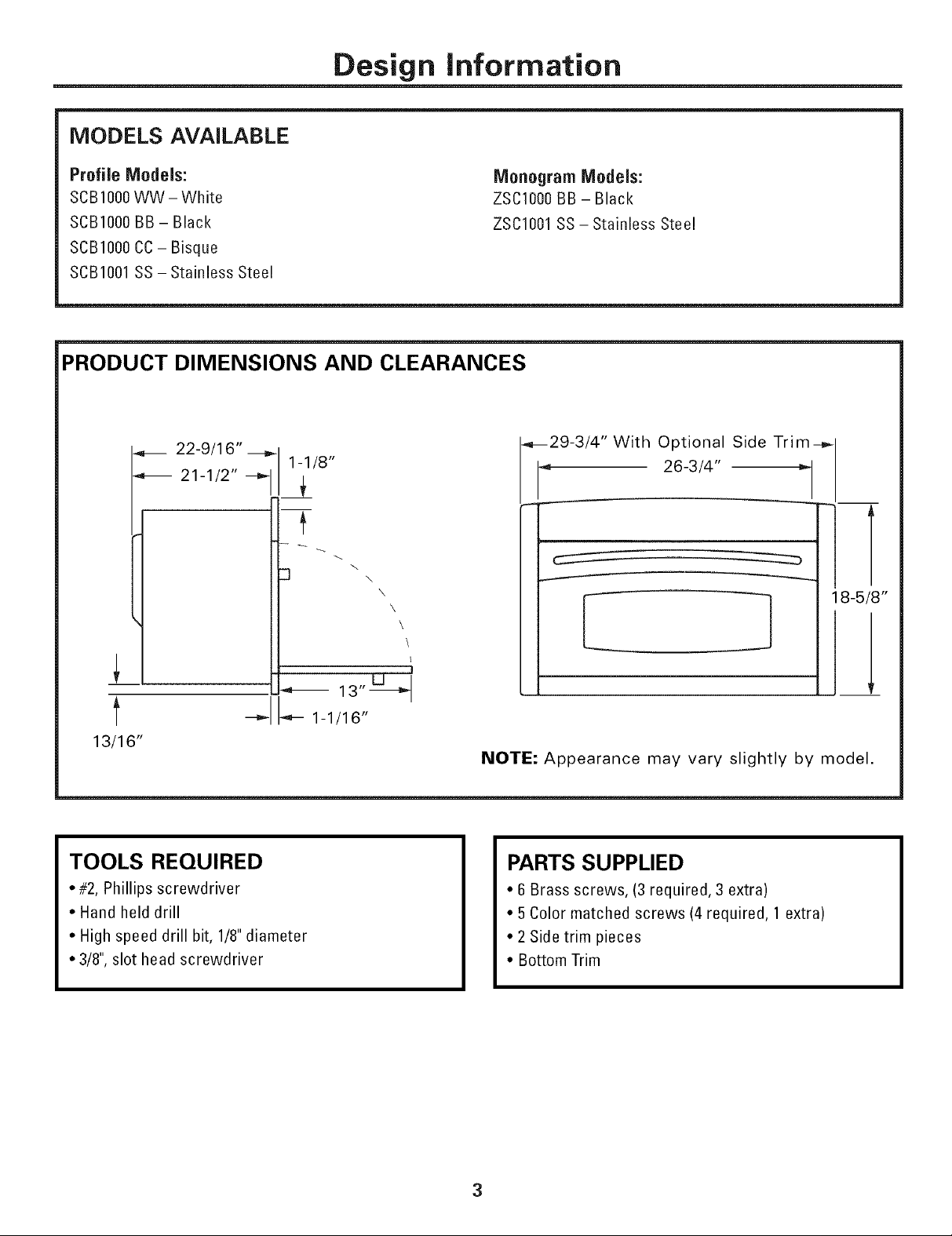
PRODUCT DIMENSIONS AND CLEARANCES
22-9/16" ---_
21-1/2" --_
_ ] 3" _-_
_-- 1-1/16"
13/16"
TOOLS REQUIRED
• #2, Phillips screwdriver
• Hand held drill
• High speed drill bit, 1/8"diameter
• 3/8", slot head screwdriver
1-1/8"
With Optional Side Trim--_
26-3/4"
_29-3/4"
1-
\
\
\
\
I
NOTE: Appearance may vary slightly by model.
PARTS SUPPLIED
• 6Brass screws, (3 required, 3 extra)
• 5Color matched screws (4 required, 1 extra)
• 2Side trim pieces
• Bottom Trim
18-5/8"
3
Page 4
Design information
ADVANCE PLANNING
These ovens may be installed directly into a 27" or
30"wide oven cabinet.
The front surface of the oven will be nearly flush with
surrounding cabinetry doors.
This oven can be installed over any GE or
GE Monogram single electric built-in oven or a
warming drawer or both.
Color matched side trim pieces are provided for
installation into a 30"wide space. Use the side trim
when installing the oven above a 30"wide wall oven or
warming drawer. Discard the side trim pieces if you are
installing over a 27"wide oven.
• Cutout dimensions are the same for both 27"or 30" wide
cabinet installations.
iMPORTANT: This oven is not approved for use above
another built-in Speedcook oven, a side by side
installation or below a countertop.
For personal safety, this oven cannot be installed in a
cabinet arrangement such as an island or peninsula.
The oven must be installed at least 36-3/4" above the
floor.
Allow for clearance to adjacent corners, walls,
drawers, etc.
Cabinets installed adjacent to wall ovens must have an
adhesion spec of at least 194°Ftemperature rating.
The oven must be securely installed in a cabinet that is
firmly attached to the house structure. Weight on the
oven door could cause the oven to tip and result in injury.
Never allow anyone to climb, sit, stand or hang on the
oven door.
4
Page 5

Installation Preparation
ELECTRICAL REQUIREMENTS
Single Advantium 120 Installation:
This product requires a 120 volt, 60 Hz, 15 amp circuit
and draws 1.8 Idlowatts. This product must be connected
to a supply circuit of the proper voltage and frequency.
• Wire size must conform to the requirements of the
National Electrical Code orthe prevailing local code for
this kilowatt rating.
• The power supply cord and plug should be broughtto a
separate 15or 20 ampere branch circuit single
grounded receptacle. The outlet box should be located
within reach of the 48" power cord.
ELECTRICAL LOCATION
6,, _L_
/i
Locate outlet box in the shaded area
Install a recessed electrical outlet in the back wall of
the opening within 6" of either side and at least 9"
above the cutout floor.
iMPORTANT: (Please read carefully).
The power cord of this appliance is equipped with a
three-prong (grounding) plug that mates with a standard
three-prong grounding wall receptacle to minimize the
possibility of electric shock. The customer should have
the wall receptacle and circuit checked by a qualified
electrician to make sure the receptacle is properly
grounded and has the correct polarity.
• Where a standard two-prong wall receptacle is
encountered, it is the personal responsibility and
obligation of the customer to have it replaced with a
properly grounded three-prong wall receptacle.
Do not, under any circumstances, cut or remove the third
(ground) prong from the power cord.
D0 NOT USE AN EXTENSION CORD.
5
Page 6

Installation Preparation
PREPARE THE OPENING
The Advantium 120 can be installed in combination
with other !3E/Monogram appliances, Always follow
each product's Installation Instructions to complete
the installation,
Single Advantium 120 Installation:
Order a 27" or 30" wide single oven cabinet or cut the
opening in awall to the dimensions shown.
27" or 30"_ 23-1/2"
4- 25-1/8"'"
17-1/2"
....... .........
36-3/4"
Min.
• Always maintain 36-3/4" minimum height from the
floor to the cutout in any single or combined
installation.
• Allow 1-1/4" case trim overlap atthe top and 7/8"
overlap on the bottom and each side of the opening.
• Oven overlaps will conceal cut edges on all sides of
the opening,
!
\
\
\
Construct
Base
Min. 3/8"
_Plywood
Supported
by2x4
orlx2
Runners all
Four Sides
PREPARE THE OPENING (CONT.I
Installation over a GE/Monogram
Warming Drawer:
23-1/2" Construct
Solid Bottom
Min. 3/8"
Plywood
Supported
/ by2x4or
lx2
Runners all
Four Sides
2x4
or2x2
Runners
or Solid
Bottom.
Must
Support
1OOIbs.
NOTE: Additional clearances between the cutouts may
be required. Check to be sure the oven supports above
the Warming Drawer location does not obstruct the
required interior depth and height. See Warming Drawer
installation instructions for details.
When installed over a single oven or a warming
drawer, allow at least 2" between the two openings.
This separation will provide clearance for bottom
overlap of the Advantium 120 and the other appliance
overlaps.
0onstruct a solid oven floor of 3/8" min. thick plywood
supported by 2 x 4 runners on all sides.
• The support must be level and rigidly mounted, flush
with the bottom edge of the cutout,
Page 7

Installation Preparation
PREPARE THE OPENING (CONT.)
Installation over a OE/Monogram Oven:
27" or 30" 23-1/2"
25-1/8"
17-1/2"
45-1/4"
Min.
Construct
Solid Bottom
Min. 3/8"
Plywood
Supported
2x4or1
x 2 Runners
all Four
Sides
Per Oven
Requirement
PREPARE THE OPENING ICONT.I
InstaJiation over a GE/Monogram Oven and
Warming Drawer:
Construct
27" or 30" 23-1/2" Solid
45-1/4"
Bottom
Min. 3/8"
Plywood
Supported
by2x4orl
x 2 Runners
all Four
Sides
-2" Min.
Per Oven
Requirement
2" Min.
* If you are replacing a GE/Monogram electric double
oven with the combined installation of an Advantium
120 and a single oven, use the dimensions shown.
The middle rail separating the two openings may
need to be larger than the 2" minimum shown.
NOTE: Additional clearances between the cutouts
may be required. Check to be sure the oven supports
above the Warming Drawer location does not
obstruct the required interior depth and height. See
Warming Drawer installation instructions for details.
CAUTION: For personal safety, the mounting surface
must be capable of supporting the cabinet load, in
addition to the added weight of this approximate 75
pound product, plus, additional oven loads of up to
50 pounds or a total weight of 125pounds.
MISE EN GARDE : Pour votre s_curit_ personnelle, la
surface de montage doit _tre capable de supporter le
poids du cabinet, en plus du poids suppl_mentaire du
produit, soit 34 kg, en plus du poids suppl_mentaire
du four pouvant aller jusqu'_ 22,7 kg, ou un poids total
de 56,7 kg.
REMOVE THE PACKAGING
• Lift the oven out of the carton.
• Remove all packing material and tape.
• Open the door and remove parts box.
• Locate parts package containing mounting screws.
Page 8

Installation
STEP 1 SLIDE THE OVEN INTO
THE CUTOUT
CAUTION: Two people are required to lift the oven
into the opening. Grasp the bottom at the front and
rear. DO NOT USE THE HANDLE TO LIFT THE OVEN.
DAMAGE WILL OCCUR!
MISE EN GARDE : Deux personnes sont n_cessaires
pour soulever le four et I'ins_rer dans I'ouverture.
Saisissez-le par le dessous, _ I°avant et _ I'arriere.
N'UTILISEZ PAS LA POIGNEE POUR SOULEVERLE
FOUR, DES DOMMAGES SE PRODUIRONT !
STEP 2 INSTALL BOTTOM TRIM
• Align bottom trim tabs to slots in the bottom of the
oveR.
=
• Secure the bottom trim to the bottom of the oven
using 3 brass screws provided.
• Lift and hold the oven at the front of the opening,
Hold the oven at a 450angle and plug in the power
cord.
• Carefully, slide the oven into the cabinet part way.
Leave the oven afew inches forward of the cabinet
frame,
• Checkto be sure the power cord is not trapped
under the oven or along the sides of the oven,
8
Page 9

Installation
STEP 3 iNSTALL SiDE TRiM
FOR 30" CABINET iNSTALLATiON ONLY. SKiP
THiS STEP iF YOU HAVE 27" WiDE CABINETRY.
J
CZ3©
CZ_ CCCC3CCCC3 CCCC3CCCC3CC3
D
l
_b
Open the oven door.
Hang the side trim pieces on the tabs behind the
oven flange.The screw holes in the side trim should
align with the holes in the oven flange.
Check to be sure the oven is pushed back into the
opening and against the cabinet frame.
STEP 4 INSTALL MOUNTING
SCREWS
CZ3©
CCZ) CCCC} CCCC3 CCCC3CCCC3CC3
• Drill pilot holes through the side flanges, 2 on each
side.
• Drive the color matched screws into the side flange
(and side trim, if applied).
STEP 5 FINALIZE INSTALLATION
• Turn power on atthe source. The interior light
should come on when the door is opened.
• Refer to the Owner's Manual for operating
instructions.
9
Page 10

Notes
10
Page 11

Notes
11
Page 12

NOTE:While performing installations described in this book,
safety glasses or goggles should be worn.
NOTE:PFodtlcr ilnpvovelnent is a continuil_g Lql(](_aVOl" at
General Electci(. Thel-et;.)re, lnatevials, _ll_pem-al_ce mid
specifi(ations _11-(_ sul_je(r to (hmlge without nori(e.
IPub.No.49-40459-1
07-05JR
PrintedinKorea
GEConsunler & Indllstria/
Appfiances
General Electric Company
Louisville, KY 40225
422005 General Electric Company
 Loading...