

Page 1

Side-by-Side Refrigerators
Design Guide
With Installation Instructions
Réfrigérateurs Côte à Côte
Buide de conception comprenant
les instructions d'installation, Page 25
Frigoríficos Lado a Lado
Guía de diseño con
instrucciones de instalación, Página 47
Doppelseitige Kühlschränke
Aufbauanleitung
mit Installationsanleitung, Seite 69
‘ Side-by-Side’ Koelkasten
Ontwerpgids
met installatie instructies, Pagina 91
Installation
Instructions
12-08 JR
monogram.com
31-46531
224D2828P001
113
Page 2
Safety Information
2
CONTENTS
Planning Guide
The Installation Space ......................................3
Dimensions and Clearances ..........................3
130° Door Swing ..................................................4
90° Door Swing ....................................................5
Customization Basics ........................................6
6 mm Framed Panel Dimensions ................7
19 mm Overlay Panel Dimensions..............8
Raised Overlay Panel Design ........................9
Side Panels ..........................................................10
Installation Instructions
Tools, Hardware, Materials ..........................10
Earthing the Refrigerator ............................10
Step 1, Remove Packaging ..........................11
Step 2, Move Refrigerator into House ....11
Step 3, Install Water Line ............................11
Step 4, Household Water Filtration ........12
Step 5, Install Side Panels ............................12
Step 6, Install Anti-Tip Brackets ................12
Step 7, Level Refrigerator ............................13
Step 8, Alternate Anti-Tip Procedure ......13
Step 9, Secure Refrigerator to Cabinetry ..14
Step 10, Adjust Door Swing ........................14
Step 11, Install Grille Panel ..........................14
Step 12, Install Framed Panels ..................15
Step 12A, Install Overlay Panels ......16, 17
Step 13, Install Dispenser Trim ..................18
Step 14, Connect Water Supply ................18
Step 15, Connect Power ..............................19
Step 16, Start Icemaker ................................19
Step 17, Install Toekick ..................................19
Tubular Handle Kit
Step 1, Remove Door Handles ..................20
Step 2, Install Handles onto Panels ........21
Step 3, Install Assembled Handles ..........22
Step 4, Install Dispenser Trim ....................22
Skill Level – Installation of this refrigerator requires
basic mechanical, carpentry and plumbing skills.
Proper installation is the responsibility of the installer.
Product failure due to improper installation is not
covered under the factory warranty.
WARNING:
• These refrigerators are top-heavy and must
be secured to prevent the possibility of tipping
forward. Anti-Tip protection is required. See page 12
for details.
• Use this appliance only for its intended purpose.
• Immediately repair or replace electric cord if it
becomes frayed or damaged.
• Unplug the refrigerator before cleaning or making
repairs.
• Repairs should be made by a qualified service
technician.
NOTE: While performing installations described in this
book, safety glasses or goggles should be worn.
BEFORE YOU BEGIN
Read these instructions completely and carefully.
• IMPORTANT– Save these instructions
for local inspector’s use. Observe all governing codes
and ordinances.
• Note to Installer – Be sure to leave these
instructions with the Consumer.
• Note to Consumer – Keep these instructions
with your Owner’s Manual for future reference.
WARNING:
This appliance must be properly grounded.
See “Earthing the Refrigerator,” page 10.
CAUTION:
Due to the weight and size of this refrigerator, and
to reduce the risk of personal injury or damage
to the product, FOUR PEOPLE ARE REQUIRED FOR
INSTALLATION OF A 42” OR 48” WIDE MODEL.
Page 3
Design Guide
3
606 mm
Behind
Frame
676 mm
102 mm Min.
to Wall
102 mm Min.
to Wall
483 mm
330 mm
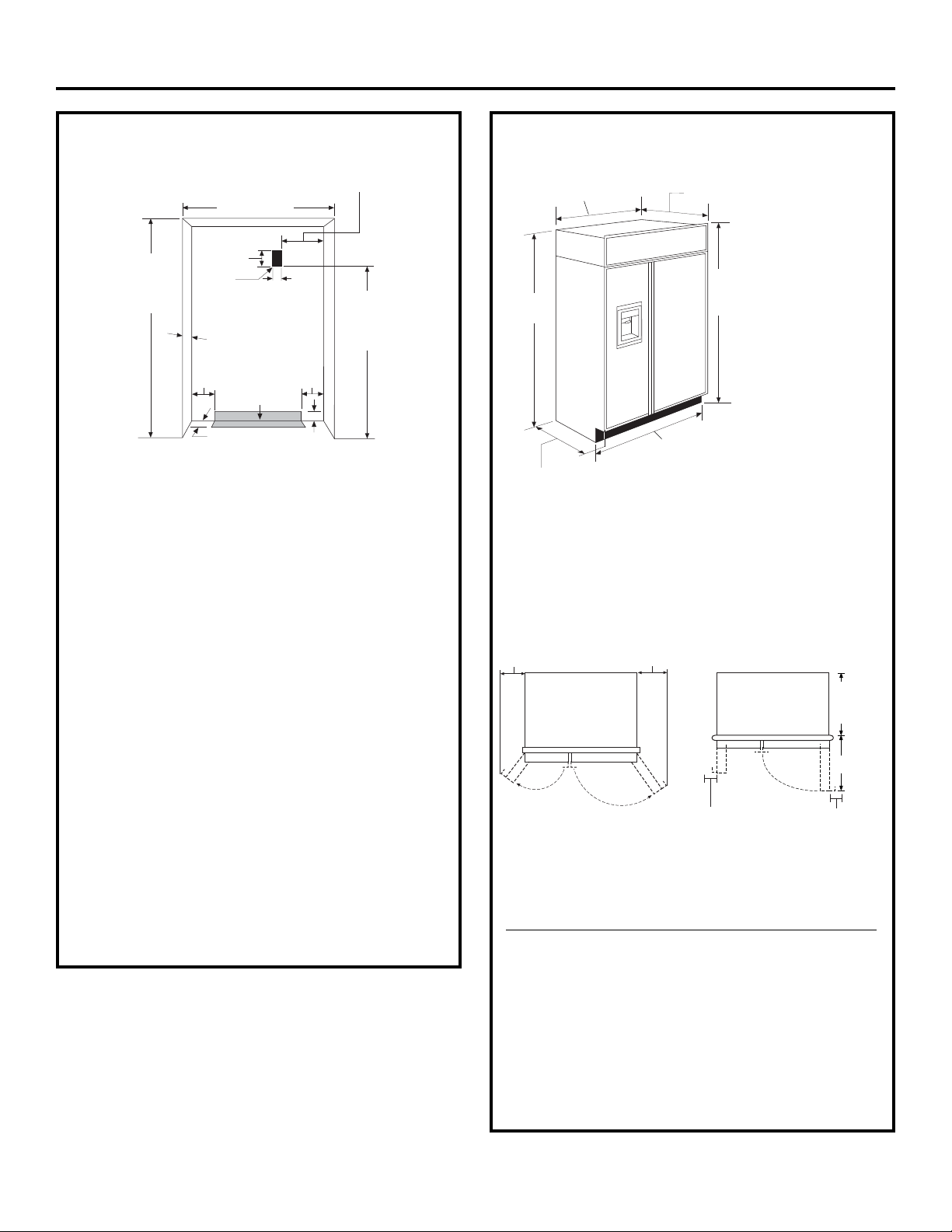
THE INSTALLATION SPACE
Water And Electrical Locations
The opening must be prepared with the electrical and
water supply located as shown.
The cutout depth must be at least 610 mm
The refrigerator will project forward, slightly beyond
adjacent cabinetry, depending on your installation.
Cutout depth beneath a soffit:
When installed beneath a soffit, the soffit cannot
exceed the 610 mm installation depth shown. The top
case trim overlaps the bottom of the soffit.
Additional Specifications
• 220 to 240 volt, 50 Hz., 4.5 amps power supply is
required. An individual properly earthed branch circuit
or circuit breaker is recommended. Install a properly
earthed electrical receptacle recessed into the back
wall. Electrical outlet must be located on rear wall as
shown.
• Use the supplied water line kit or GE SmartConnect
™
Refrigerator Tubing kit to connect the water line
on the refrigerator to the house water supply.
Installation of an easily accessible shut-off valve
in the water line is required.
DIMENSIONS AND CLEARANCES
Product Clearances
These refrigerators are equipped with a 2-position
doorstop. The factory-set 130° door swing can be
adjusted to 90° if clearance to adjacent cabinets or
walls is restricted.
*Finished cutout width must be:
1054 mm for 42” Models
1207 mm for 48” models
90° Door Swing130° Door Swing
* Shipping height.
The refrigerator can
be adjusted to fit into a
cutout that is 2121 min.
to 2146 mm max. height.
Note that the top case
trim at the front is 13 mm
higher and will overlap
upper cabinetry or soffit.
Use leveling legs and
wheels for a maximum
25 mm height adjustment.
Allow minimum clearances for the freezer door
(Dimension A) and fresh food door (Dimension B)
for a full 130° door swing and to allow for pan removal.
Models A B C
42” 330 mm 483 mm 676 mm
48” 381 mm 508 mm 727 mm
For a 90° door swing, allow 101.6 mm min. clearance
to a wall for framed and stainless steel models. Allow
127 mm min. clearance for professional series models.
If the 90° doorstop position is used, pan access is
maintained, but pan removal is restricted.
See the illustrations on pages 4 and 5 to determine door
swing interaction with adjacent cabinets or countertops.
*Finished Width
42” Models, 457 mm
48” Models, 508 mm
2146 mm Max.
2121 mm Min.
Finished
Opening
610 mm
127 mm
127 mm
Water Supply
89 mm
89 mm
127 mm
152 mm
Electrical
Area
1905 mm From
Floor to Bottom
of Electrical
Area
645 mm Framed Models
654 mm Stainless Steel Models
Case Depth
Case Width:
1041 mm for 42” Models
1194 mm for 48” Models
*2121 mm
at Rear
*2134 mm
From Floor
to Top Frame
Frame to Frame:
1067 mm for 42” Models
1219 mm for 48” Models
Depth Including Handles:
683 mm Framed Models
729 mm Professional Models
A
B
C
606 mm
Behind
Frame
Page 4
6 mm
13 mm
19 mm
25 mm
32 mm
25 mm
19 mm Overlay
Panel
(Nominal Size)
6 mm
13 mm
19 mm
51 mm
32 mm
38 mm
44 mm
76 mm
57 mm
64 mm
70 mm
6 mm
13 mm
19 mm
Door
6060 mm From
Rear of
Refrigerator
25 mm
Refrigerator
Case
Trim
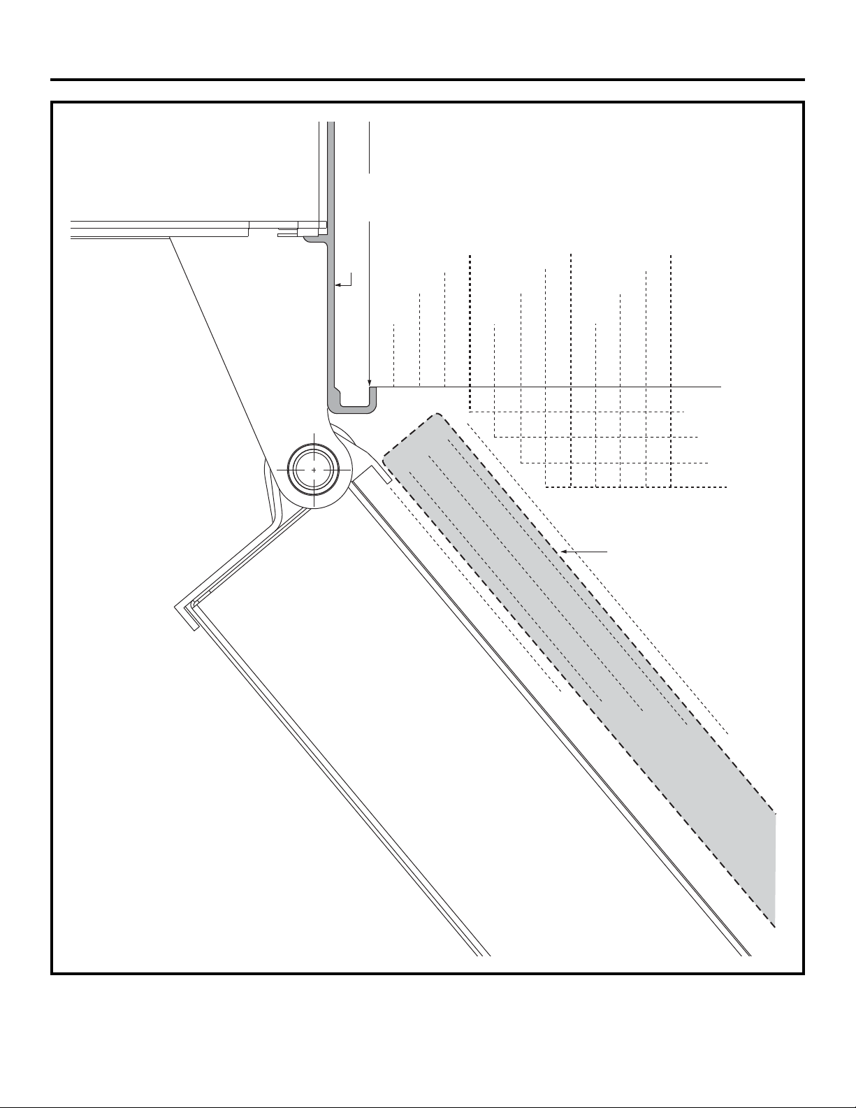
Design Guide
Top View
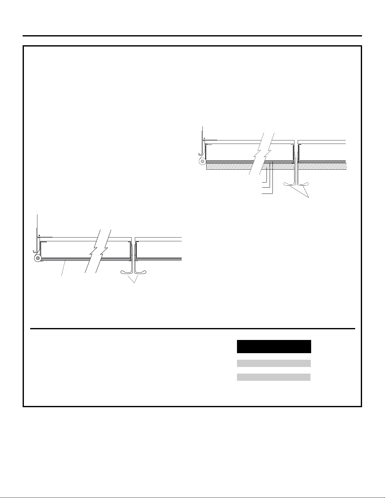
130° DOOR SWING
(factory setting)
Scale 1:1
IMPORTANT NOTE –
FOR DISPENSER MODELS:
Dispenser models are supplied with two
dispenser trims, one to fit framed panels
and one for overlay panels. Dispenser trim
fit to the custom panel depends on correct
panel thickness. Framed panels must be
6 mm nominal. Overlay panels should be
constructed as shown to accomplish a total
28 mm thickness. See pages 7 and 8
for details.
4
Frameless Cabinets: The case trim overlaps
cabinets at the top and sides. Therefore,
frameless cabinets may require filler strips
to prevent interference with cabinet door
swing. The opening must allow for filler strips.
Page 5
6 mm
13 mm
19 mm
25 mm
32 mm
6 mm
13 mm
19 mm
25 mm
32 mm
38 mm
606 mm
From Rear of
Refrigerator
19 mm Overlay
Panel
(Nominal Size)
Case Trim
Refrigerator
Door
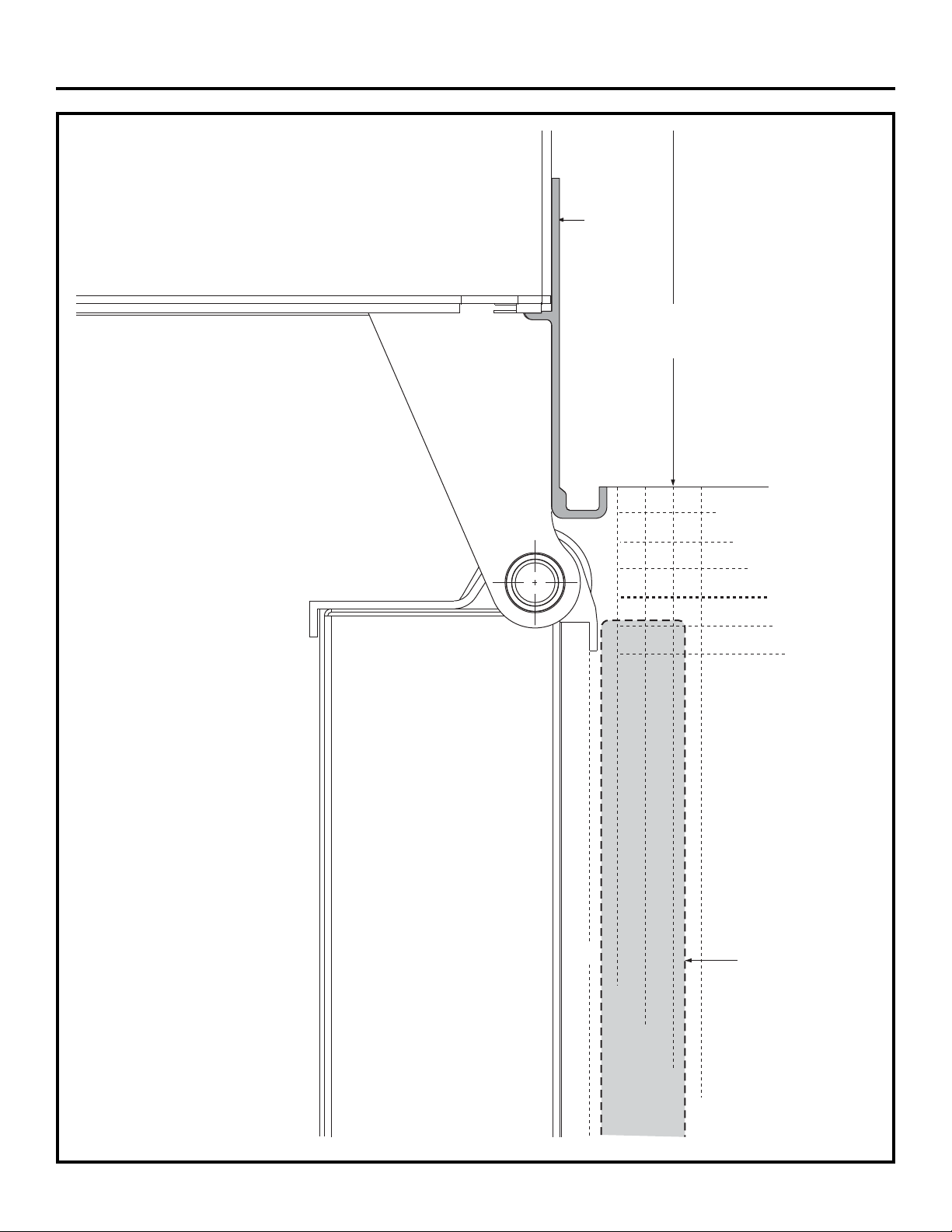
5
Top View
90° DOOR SWING
(optional setting)
Scale 1:1
IMPORTANT NOTE –
FOR DISPENSER MODELS:
Dispenser models are supplied
with two dispenser trims, one to fit
framed panels and one for overlay
panels. Dispenser trim fit to the
custom panel depends on correct
panel thickness. Framed panels
must be 6 mm nominal. Overlay
panels should be constructed as
shown to accomplish a total
28 mm thickness. See pages 7
and 8 for details.
Frameless Cabinets:
The case trim overlaps
cabinets at the top
and sides. Therefore,
frameless cabinets may
require filler strips to
prevent interference
with cabinet door swing.
The opening must allow
for filler strips.
Design Guide
Page 6
CUSTOMIZATION BASICS:
Framed Or Overlay Panels, Custom Handles and Accessory Kits
Overlay panels
You may also choose to install custom overlay panels
from your cabinet manufacturer. This design provides
a seamless appearance which integrates smoothly with
surrounding cabinetry.
Standard supplied handles shown in 19 mm overlay panel position.
Professional Style Stainless Steel Refrigerators
Stainless steel wrapped refrigerators have beveled edges
and professional-style handles. These models are shipped
ready for installation.
Trimmed Refrigerators
Trimmed refrigerators are designed to be customized
with decorative panels. Field installed custom door
and grille panels are required.
Framed panels
You may install 6 mm-thick custom panels from
your cabinet manufacturer. The decorative panel slides
into the factory installed trim. Order black or stainless steel
accessory panels from your Monogram dealer.
6
Standard supplied handles shown in 6 mm panel position.
Door Handles
The standard supplied handles can be adjusted to
accommodate both framed or overlay panels. Custom
handles of your choice, supplied by your cabinetmaker
can also be installed on 19 mm overlay panels. If desired,
you may order ZKHSS2 Monogram stainless steel
tubular handle kit for 19 mm overlay panels.
Side Panels
Side panels must be used whenever the sides
of the refrigerator will be exposed.
Optional Accessory Kits
ZKHSS2: Monogram tubular stainless steel handles
designed to fit 19 mm overlay panels.
Accessory Panels
Black and stainless steel accessory panels are available
from your Monogram dealer. Panels are cut to size and
ready to install.
Black
Models Acrylic
ZISB480D ZPB480D
ZIS480N ZPB480N
ZISB420D ZPB420D
ZIS420N ZPB420N
Framed Panel
Standard Door Handles
Design Guide
19 mm Overlay Panel
3 mm Thick Spacer Panel
6 mm Thick Backer Panel
Standard Door Handles
Page 7
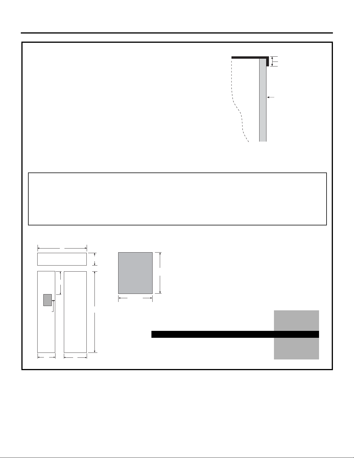
6 mm FRAMED PANEL DIMENSIONS
7
If you choose to install framed panels, they must
be cut to the dimensions shown. The panels will slide
into the frame on the door and grille.
Non-Dispenser Models
If the custom panel is less than 6 mm thick and it fits
loosely in the door frame it can be backed up with
a piece of filler material or foam tape to improve
the fit.
IMPORTANT NOTE: Maximum total panel weight:
• Fresh food door panel – 34 kg.
• Freezer door panel – 24 kg.
• Grille Panel – 8 kg.
The framed panel must be 6 mm nominal thickness
to fit the dispenser trim.
IMPORTANT NOTE – DISPENSER MODELS
The refrigerator is supplied with two dispenser trims,
one for framed panels and one for overlay panels.
• If the panel is less than 6 mm thick, a noticeable gap
may be created around the dispenser trim. Foam
tape may be applied on the door to improve the fit.
• If the panel is more than 6 mm thick, the dispenser
trim cannot be secured to the door.
See Dispenser Trim Fit Examples, page 9.
Design Guide
244 mm
Dispenser Cutout
391 mm
Fresh Food
Panel
Freezer
Panel
E
D
F
G
A
B
Grille Panel
C
Dispenser
Cutout
Side-by-Side (in millimeters)
AB C D E F G
1013 mm 241 mm 1737 mm 370 mm 624 mm 452 mm 79 mm
1165 mm 241 mm 1737 mm 471 mm 675 mm 452 mm 130 mm
Dispenser
Cutout Position
6 mm
Panel
Door
8 mm
Trim
Reveal
42” Models
48” Models
Page 8
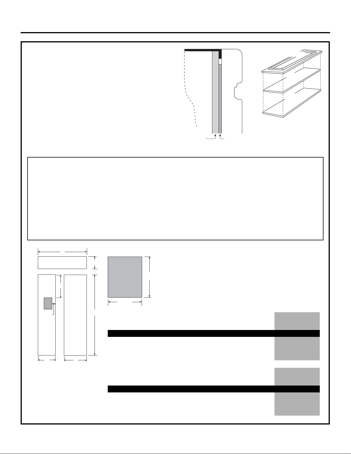
19 mm OVERLAY PANEL DIMENSIONS
For a more custom appearance, overlay panels may
be installed on trimmed models. The overlay panel must
be secured to a 6 mm thick backer panel which slides
into the trim. A spacer panel 3 mm thick must be placed
between the overlay and backer panel.
Assemble the panels with glue and screws:
• Center the spacer panel on the backer panel, left to
right and top to bottom. Secure the panels with glue.
• Center the spacer and backer panel on the overlay
panel and secure with glue and screws. Screws must
be countersunk into the backer panel.
NOTE: Left-to-right offset is not
always equal to top-to-bottom
offset.
8
Spacer Panel
Overlay Panel
Backer Panel
Fresh Food
Panel
Freezer
Panel
E
D
F
G
A
B
Grille Panel
C
Dispenser
Cutout
*Cut the dispenser opening after the backer, spacer and overlay
panels have been assembled.
IMPORTANT NOTE: Maximum total weight for the assembled
panels:
• Fresh food door panel – 34 kg.
• Freezer door panel – 24 kg.
• Grille Panel – 8 kg.
IMPORTANT NOTE – DISPENSER MODELS
The refrigerator is supplied with two dispenser trims,
one for framed panels and one for overlay panels. The
overlay dispenser trim is designed to fit a total panel
thickness of 28 mm.
• If the panel is less than 28 mm a noticeable gap may
be created around the dispenser trim.
• If the panel is more than 28 mm the dispenser trim
cannot be secured to the door.
See Dispenser Trim Fit Examples, page 9.
6 mm + 3 mm + 19 mm = 28 mm Total Panel Thickness
• The overlay panel must be constructed according to
the specifications shown to achieve the correct total
thickness.
• Alternative panel construction methods such as
securing a 19 mm panel to a 6 mm backer panel
cannot be used. Another method, routing a 19 mm
thick panel on all sides, cannot be used. These
methods will not result in the required 28 mm panel
thickness.
When a raised panel design is to be used, a custom
middle rail is required. See page 9 for details.
Design Guide
244 mm
Dispenser Cutout
391 mm
*Dispenser
Cutout Position
42” Side-by-Side (in millimeters)
ABCDEFG
6 mm Backer Panel 1013 mm 241 mm 1737 mm 370 mm 624 mm
3 mm Spacer Panel 991 mm 219 mm 1702 mm 337 mm 591 mm
19 mm Overlay Panel 1019 mm 248 mm 1743 mm 376 mm 630 mm 456 mm 133 mm
19 mm
Overlay
Panel
6 mm
Backer
Panel
Door
3 mm
Spacer
*Dispenser
Cutout Position
48” Side-by-Side (in millimeters)
ABCDEFG
6 mm Backer Panel 1165 mm 241 mm 1737 mm 472 mm 699 mm
3 mm Spacer Panel 1143 mm 219 mm 1702 mm 438 mm 641 mm
19 mm Overlay Panel 1172 mm 248 mm 1743 mm 462 mm 681 mm 456 mm 133 mm
Page 9

DISPENSER MODELS:
RAISED OVERLAY PANEL DESIGN
When a raised panel design is to be used,
a custom wide middle rail is required to accept
the dispenser trim.
• The middle rail must be wide enough to allow
for the dispenser trim to overlap the opening.
• The middle rail must be 28 mm total thickness
to accept the dispenser trim.
9
DISPENSER TRIM FIT EXAMPLES:
(NOT TO SCALE)
6 mm FRAMED PANEL
• The dispenser trim fits over the custom
panel and snaps into the freezer door.
• The clips will not engage the door
if the panel is more than 6 mm thick.
• If the panel is less than 6 mm thick,
a noticeable gap may be created
around the dispenser trim.
19 mm OVERLAY PANEL
• The dispenser trim fits over the custom
panel and snaps into the freezer door.
• The clips will not engage the door
if the panel is more than 28 mm thick.
• If the panel is less than 28 mm thick,
a noticeable gap may be created
around the dispenser trim.
Design Guide
6 mm Backer Panel
3 mm Spacer
19 mm Overlay Panel
Wide
Middle
Rail is
Required
Dispenser
Trim
425 mm
270 mm
6 mm
Framed
Panel
6 mm Backer Panel
3 mm Spacer
Panel
6 mm Dispenser Trim
19 mm Overlay Dispenser Trim
19 mm Overlay
Panel
FREEZER DOOR
FREEZER DOOR
6 mm
Thick
28 mm
Total Thickness
Ice / Water Dispenser
Ice / Water Dispenser
Page 10

10
SIDE PANELS
Side panels must be used
whenever the sides of the
refrigerator will be exposed.
The 6 mm side panels will
slip into the side case trim.
Secure the panels to the
refrigerator with stick-on
hook and loop fastener
strips. Order the side
panels from the cabinet
manufacturer.
• Cut a notch in the top
front corner as shown
to allow clearance for
corner keys in the front
side trim.
* Depending on installation height.
Design Guide
EARTHING THE REFRIGERATOR
IMPORTANT—(Please read carefully)
FOR PERSONAL SAFETY, THIS APPLIANCE MUST BE
PROPERLY EARTHED.
The power cord of this appliance is equipped with an
earthing plug which mates with a standard earthed
wall receptacle to minimize the possibility of electric
shock hazard from this appliance.
Have the wall outlet and circuit checked by a qualified
electrician to make sure the outlet is properly earthed.
Where an unearthed wall outlet is encountered, it is
your personal responsibility and obligation to have
it replaced with a properly earthed wall outlet.
IMPORTANT: The refitting of
electric plugs and cables should
be done by a qualified technician
or service agent. In some countries
the refitting of electric plugs and
cables is only permitted when the
work is completed by a qualified
technician.
NOTE: Plug type shown may not
match to the plug on your refrigerator
depending on the country of the sale.
Mains lead replacement
If the mains lead on your refrigerator needs
replacing at any time, it must be replaced by a
special lead which is obtainable from your local
dealer. A charge will be made for the replacement
of the mains lead if you have damaged the lead.
Unplug the unit or turn off the main switch on the
switchboard before servicing or repairing the
refrigerator. To unplug the unit, pull the refrigerator
away from the wall and then unplug it.
FLOORING
For proper installation, this refrigerator must be placed
on a level surface of hard material that is at the same
height as the rest of the flooring. This surface should be
strong enough to support a fully loaded refrigerator, or
approximately 680 kg.
NOTE: Protect the finish of the flooring. Cut a large
section of the cardboard carton and place under the
refrigerator where you are working.
Ensure proper
earthing
exists
before
using.
Earthing
Plug
*2134 mm
65 mm
610
mm
*76 mm to
102 mm
5 mm
48 mm
TOOLS AND MATERIALS REQUIRED
• Tin snips to cut banding
• Stepladder
• 1" Bit extenion
• Tape measure
• 1/4" Drywall screws
• Bucket
• Level
• Appliance hand truck
• Tubing cutter
• 7/16" Open-end wrench
• #2 Phillips screwdriver
• Drill and appropriate bits
• 5/16", 7/16" Socket
• Safety glasses
• 1-1/8" Open-end wrench
• Pliers
• 1/4", 5/16" Combo ratchet
• 900 mm x 50 mm x 100 mm Wood block
for Anti-Tip support
• Supplied water line kit or GE SmartConnect
™
Refrigerator Tubing kits
• Water shut-off valve
• Custom panels for doors and grille panel
• Screws to secure refrigerator to cabinetry
• Stick-on hook and loop fastener strips for
6 mm side panels
HARDWARE SUPPLIED
• Water filter bypass plug
• Anti-Tip brackets
• 1/4" nut and ferrule
• Dispenser trims for 6 mm and 19 mm overlay panels
• 12 pan-head screws for custom handle installation
Page 11

Installation Instructions
STEP 1 REMOVE PACKAGING
CAUTION: The refrigerator is much heavier
at the top than at the bottom—be careful when moving.
When using a hand truck, handle from the side only.
• Carefully cut banding at the top and bottom.
Remove the outer carton.
• Slide out the back corner posts (2).
• Slide the carton off the top of the cabinet.
NOTE: IT IS NOT NECESSARY TO LAY THE CABINET DOWN
IN ORDER TO REMOVE THE SKID!
• The unit is secured to the skid with 4 slotted
tie-down straps. Remove the six 7/16" bolts
from the base channels in the tie-downs.
• Remove the six 7/16" bolts securing the straps
to the skid.
CAUTION:
DO NOT ATTEMPT TO ROLL
UNIT OFF SKID.
STEP 3 INSTALL WATER LINE
• A cold water supply is required for automatic icemaker
operation. The water pressure must be between
2.75 bar (275000 pascal) and 8.25 bar (825000 pascal).
• Route the supplied water line kit or GE SmartConnect
™
plastic tubing between the house cold water line and
the water connection location.
• The tubing should be long enough to extend
to the front of the refrigerator. Allow enough tubing
to accommodate the bend leading into the water line
connection.
NOTE: The only GE-approved plastic tubing is supplied in
the GE SmartConnect™Refrigerator Tubing kits.
Do not use any other plastic water supply line because
the line is under pressure at all times. Other types
of plastic may crack or rupture with age and cause
water damage to your home.
GE SmartConnect™Refrigerator Tubing Kits are
available in the following lengths:
0.6 m WX08X10002
1.8 m WX08X10006
4.6 m WX08X10015
7.6 m WX08X10025
11
Remove
Tie Downs
Toekick
• The support blocks on the bottom of the refrigeration
case must be removed before the refrigerator is taken
off the skid or damage will occur. Carefully tilt the
refrigerator and slide the blocks out from beneath.
• Remove the toekick and set aside for final installation.
• Lift the refrigerator off the skid with an appliance dolly.
Handle from the sides.
STEP 2 MOVE THE REFRIGERATOR INTO THE HOUSE
• Re use the corner posts from the packaging to protect stainless steel models. Run the appliance dolly straps over
the posts and under the handles.
• Leave the protective film on the refrigerator until installation is complete.
IMPORTANT: Never lift the refrigerator by the handle or push against the grill panel; this could cause damage
or misalignment.
• Avoid laying the unit on its back or side to prevent sealed system restrictions which can damage the product.
Shut off the main water supply.
Turn on the nearest faucet long enough to clear the line
of water.
• Install a shut-off valve between the icemaker water
valve and cold water pipe in a basement or cabinet.
The shut-off valve should be located where it will be
easily accessible.
• Turn on the main water supply long enough to flush
out the debris thoroughly. In new home construction,
there may be a high level of copper residue in the
supply pipe, which can damage plastic tubing. Make
sure to flush the supply pipe thoroughly before you
install the water line kit. Shut off the water supply at
the shut-off valve. See Step 14 for details of
connecting the water supply.
NOTE: Shut-off valves are included in many water
supply kits. Before purchasing, make sure a valve
complies with your local plumbing codes.
Floor
Copper Tubing or
GE SmartConnect Tubing
Supplied Water Line Kit or
GE SmartConnect Tubing
Page 12

12
STEP 4 INSTALLATION WITH
HOUSEHOLD WATER
FILTRATION SYSTEM
Skip this step if you do not have a household water
filtration system.
If the water supply to the refrigerator is from
any household water filtration system, the filter
cartridge should be removed. For better ice and water
performance, remove the filter and install the filter
bypass plug.
STEP 5 INSTALL SIDE PANELS
Skip this step when not using side panels.
If you are using 6 mm side panels, they should
be inserted into the case trim. Fasten the panels
to the refrigerator with stick-on hook and loop
fastener strips before setting the refrigerator in place.
STEP 6
INSTALL ANTI-TIP BRACKETS
WARNING:ANTI-TIP PRECAUTIONS
The refrigerator is top-heavy and must be secured
to prevent the possibility of tipping forward.
• Cut a 50 mm x 100 mm x 900 mm wood block.
Secure the block to the mounting brackets provided
using 6 mm diameter wood screws.
• Secure the bracket with the wood block to the back
wall so that it is 2134 mm (or your installation height)
from the finished floor. Use 6 mm diameter wood
screws.
• The screws must penetrate at least 25 mm
into the vertical wall studs.
Connect power cord:
• Before pushing the refrigerator into the opening, plug
the power cord into the receptacle. Open the grille
panel and reach into the opening at the back to grasp
the power cord. Pull the power cord into the opening
as you push the refrigerator back.
• Gently push refrigerator into the opening with hands
against front corners.
IMPORTANT NOTE: When the refrigerator is installed under a soffit
or if there is not enough height for this method of security, brackets
cannot be used. Proceed to Step 7 to level the refrigerator and then to
Step 9 to secure refrigerator to cabinets. See Step 8 if you have metal
wall studs. The refrigerator must be secured to prevent tipping.
Block
Soffit
Side View
Height
From
Floor
to
Bottom
of Wood
Block
Brackets
Required
Brackets
Not Required
Beneath a
Soffit
Installation Instructions
Filter Bypass Plug
Rotate Clockwise To Remove
Mounting
Bracket
50 x 100 mm
Cut 900 mm
Length
Installation
Height
From Floor
Screws Mounted into
Vertical Wall Studs
Page 13

13
STEP 7 LEVEL REFRIGERATOR
All models have 4-point leveling. The front is
supported by leveling legs, and the rear is supported
by adjustable wheels. Both are accessible from
the front of the refrigerator.
• To level the back of the refrigerator, turn the
7/16" hex nut located above the front wheels.
Turn clockwise to raise or counterclockwise to
lower the refrigerator.
• For front leveling, use a 1-1/4" open-end wrench.
• Adjust height of refrigerator to match installation
cutout opening 2121 mm to 2146 mm. The
refrigerator should be level and plumb with cabinetry.
STEP 8 ALTERNATE ANTI-TIP
PROCEDURE
The refrigerator must be secured to prevent tipping.
The anti-tip brackets cannot be used on metal
wall studs. Use this Alternate Procedure to secure
the refrigerator against tip-over whenever metal
wall studs are encountered and there is no soffit.
• Raise the grille panel to access case trim.
• Use a 3/16" bit to drill four evenly spaced clearance
holes through the metal top case trim.
• Use a 1/16" bit to drill to pilot holes through the metal
clearance holes and into the wood soffit. The holes
should be centered in the soffit or a 19.05 mm min.
wood brace. The brace spanning the enclosure must
be securely fastened to cabinets on both sides.
• Install four, 1-1/2" drywall screws into the pilot holes.
Hex Nut Adjusts
Rear Wheels
Leveling Leg
Installation Instructions
CAUTION:
The rear leveling wheels and front leveling legs are
limited to a maximum height adjustment of 25 mm. If
the installation requires more than 2146 mm height,
the installer should elevate the refrigerator on a sheet
of plywood or runners. Cabinetry trim could also be
added across the top of the opening to shorten the
opening. If you attempt to raise the refrigerator more
than 25 mm, you will damage the front leveling legs
and the rear leveling wheels.
19.05 mm
Min.
Install Four
1-1/2" Drywall Screws
Through Trim and Into Soffit
or 19.05 mm Min. Wood Brace
Top Case Trim
Side View
Top Case Trim
Page 14

STEP 11 INSTALL GRILLE PANEL
(for Custom Panel Models only)
To insert the framed or overlay panel into the grille:
• Raise the grille panel to the stop position.
14
• Loosen the screws on the side trim behind the frame.
Remove the bottom trim.
CAUTION: The metal panel may be
slippery. Grip the metal panel firmly so the panel
does not slip out of the frame and cause personal
injury or damage to the frame.
• Slide the panel over the metal backer panel and into
the trim.
• If necessary, tap with a wood block until the panel
slips under the top trim piece.
• Reassemble the bottom trim. Tighten the screws.
• Adjust the hinge spring to accommodate the panel
weight, if necessary.
Adjust Nut Below
Spring to Accommodate
Panel Weight
Loosen
Side
Trim
Screw
Loosen
Side
Trim
Screw
Installation Instructions
STEP 10 ADJUST DOOR SWING
NOTE: This refrigerator has a 2-position door stop.
When space does not allow the door to swing open
fully to 130°, you may change the door swing to a 90°
opening. Skip this step if door opening is satisfactory
for your installation situation.
• Open the door to view the bottom hinge.
Note the door stop pin locations. The pin is factoryinstalled in the 130° position.
• Close the door. From below, use pliers to unscrew
the door stop and reinstall into the 90° position.
90˚
130˚
Hinge
Interior
Door
STEP 9 SECURE REFRIGERATOR
TO CABINETRY
Whenever possible, perform this step for anti-tip
security or when anti-tip brackets cannot be used.
The refrigerator must be secured to prevent tipping.
• Raise the grille panel to access the case trim.
• Drill a hole in the trim and drive a 6 mm diameter
screw through the trim into the adjacent cabinet.
• Follow the same procedure on the opposite side.
Drive Screws
Through Case Trim Into
Adjacent Cabinets
Raise Grille Panel
to Stop Position
Page 15

15
STEP 12 INSTALL FRAMED PANELS
Install door panels:
• Open the door to 90°. Remove the 6 Phillips-head screws
from the door handle.
• Remove the handle. Retain all screws.
• Remove the 6 screws holding the trim, then lift off
the trim. Retain the screws.
• Slide the framed panel into the door trim.
Dispenser Models Only:
• The dispenser controls protrude beyond the face
of the freezer door. To avoid damage to the dispenser,
the trim at the top of the door should be removed.
• Remove the screws holding the top trim in place.
• Place the freezer panel into the bottom channel
and slide into the hinge side trim.
• Reinstall the top trim piece with screws.
• There are two sets of holes in the handle side trim.
Replace the handle side trim by installing the original
screws in the FRONT screw holes.
• Secure the handle to the door using the REAR screw
holes.
• Follow the same procedures to install the opposite panel.
• Check to be sure the handles are evenly aligned with
each other at the top. To adjust, loosen the handle
screws and slide up or down. Tighten the screws.
NOTE: Aluminum cover trim is supplied for use with
custom handles on overlay panels. It is not intended for
use with 6 mm panels. Discard the cover trim when using
6 mm framed panels.
Go to Step 10A for Overlay Panels
Supplied Handle
Shown in 6 mm
Panel Position
Use Rear Holes
to Secure Handle
Use Front Holes
to Secure Trim
Refrigerator
Door
Door Trim
Handle
Trim
Installation Instructions
Page 16

16
STEP 12A INSTALL OVERLAY PANELS
Install door panels:
• Open door to 90°. Remove the 6 Phillips-head screws
from the door handle.
• Remove the handle. Retain all screws.
• Remove the 6 screws holding the trim, then lift off
the trim. Retain the screws.
• Slide the overlay panel into the door trim.
Dispenser Models Only:
• The dispenser controls protrude beyond the face
of the freezer door. To avoid damage to the dispenser,
the trim at the top of the door should be removed.
• Remove the screws holding the top trim in place.
• Place the assembled freezer panel into the bottom
channel and slide into the hinge side trim.
• Reinstall the top trim piece with the screws.
• There are two sets of holes in the handle side trim.
Replace handle side trim by installing the original screws
in the REAR screw holes.
• Secure the handle to the door using the FRONT
screw holes.
• Follow the same procedures to install the opposite panel.
• Check to be sure the handles are evenly aligned with
each other at the top. To adjust, loosen the handle
screws and slide up or down. Tighten the screws.
Use Rear Holes
to Secure Trim
Use Front Holes
to Secure Handle
Supplied Handle
Shown in Overlay
Panel Position
Installation Instructions
Refrigerator
Door
Door Trim
Handle
Trim
Move
Forward
For 19 mm
Panel
Page 17

17
STEP 12A (continued)
Custom Handles
• If you are using custom handles, the handle must
be properly secured to the overlay panel before sliding
the panel into the trim.
• The cabinet manufacturer will supply the custom
handle and hardware.
• Discard the supplied handle.
• Remove the trim. Peel away a few inches
of the adhesive backing.
IMPORTANT: The tape is very sticky and strong. Once
it adheres to a surface, it cannot be removed without
damaging both surfaces. Do not install the trim before
the final wood panels are in place. Be sure to align
the trim carefully before removing the paper backing.
Reinstall all original screws.
• Reinstall the handle side trim, using all 12 supplied
flat-head screws, plus the 12 flat-head screws
originally installed in the handle trim.
• Install a supplied end cap onto the top of the door,
using a Phillips-head screwdriver and the 2 screws
provided. Hand-tighten the screws into the end caps.
Do not overtighten; damage will occur.
• Clean the aluminum trim with rubbing alcohol—
do not use alcohols with oil or lanolin that will prevent
adhesion of double-sided tape.
• Slip the aluminum cover trim behind the top end cap
to check the fit. The aluminum cover trim has a recess
on each end which fits the end cap.
Installation Instructions
Top End Cap Fits Over
the Aluminum Trim.
Secure Cap with
2 Screws.
End Cap
STEP 12A (continued)
• Carefully place the aluminum cover trim into the top
end cap so that the recess is aligned with the cap.
Use the top-to-bottom grooves along the handle side
to align the cover trim accurately. Pull the tape a few
inches at a time while pressing the trim against
the door. Press and hold approximately 10 seconds
before continuing along the length of the door.
• Install another end cap at the bottom of the door
to secure the cover trim. Use a stubby Phillips-head
screwdriver and the 2 screws provided.
• NOTE: Make sure there are no gaps in the installation.
• Follow the same procedure on the opposite door.
Insert Aluminum
Trim Into End Cap.
Cover Trim
End Cap
Page 18

18
STEP 14 CONNECT WATER SUPPLY
NOTE: The new hose sets supplied with the appliance
are to be used. Discard old hose sets.
Supplied Water Line Kit:
• Turn on the water to flush out debris from the line
thoroughly and then shut off the water valve.
• Connect the adapt tab on the supplied water line kit
to the end of the tubing coming from the house cold
water supply.
• Insert the molded end of the tubing into the
refrigerator connection at the back of the refrigerator
and tighten with the compression nut until it is handtight. Tighten one additional turn with the wrench,
being careful not to overtighten. Overtightening may
cause leaks.
• Turn on the water to check for leaks.
GE SmartConnect™Tubing:
• Insert the molded end of the tubing into the
refrigerator connection. Tighten the compression
nut until it is just hand-tight.
• Tighten one additional turn with a wrench.
Overtightening can cause leaks!
• Turn on the water to check for leaks.
STEP 13 INSTALL DISPENSER TRIM
Skip this step is you are installing a stainless steel
wrapped or a non-dispenser refrigerator.
There are two dispenser trims shipped with your
refrigerator. Select the appropriate trim for your
application.
• Press and snap the dispenser trim into the dispenser
recess on the refrigerator door.
If an excessive gap exists around the dispenser trim
or if the panel fits loosely in the door frame, foam tape
may be applied to help improve the fit. Remove
the trim and panel and apply the foam tape
to the door around the dispenser and in the corners.
Compare the dispenser trims. Note that
the inside depth of the frames are different.
Choose the trim with less depth for framed
panels. Choose the deeper one for overlay
panels.
Dispenser trim fit over the custom panel depends on
correct panel thickness. See pages 7 and 8 for panel
construction information.
Framed
Panel
Trim
Overlay
Panel
Trim
Refrigerator
Water Supply
House
Water Supply
Installation Instructions
Page 19

19
STEP 17 INSTALL TOEKICK
• Locate the supplied toekick (shipped taped to
the side of the refrigerator). Install with the 2 screws
provided. Adjust to the desired height and tighten
the screws.
• A custom toekick can be installed to match
or complement the surrounding cabinetry.
Use the supplied toekick as a template
to cut the shape.
STEP 15 CONNECT POWER, CLOSE
GRILLE PANEL
• Open the grill panel.
• Plug in the power cord (if necessary) by reaching
into the opening next to the water filter. If access is
too tight, remove the 2 screws holding the water
filter bracket and move aside. Plug in the power cord
and secure the bracket with the original screws.
• Check to make sure power to refrigerator is on
by opening refrigerator door to see if interior lights
are on.
• The temperature controls are preset at 3°C for
the fresh food section and -18°C for the freezer.
• Allow 24 hours to stabilize before making
adjustments.
Supplied Toekick
1/4" or Thicker Toekick
INSPECT FINAL INSTALLATION
Check door alignment
Stand back away from the refrigerator to inspect
the final installation.
• Check to be sure the handles are evenly aligned with
each other at the top. To adjust, loosen the handle
screws and slide up or down. Tighten the screws.
• Shipping or the addition of heavy door panels
may have caused the doors to move slightly out
of alignment.
• If necessary, the fresh food door may be adjusted up
or down to align with the freezer door.
• Use a 5/16" wrench to adjust the hinge pin as shown.
Bushing
Door Hinge
Case Hinge
5/16" Wrench
Raise
Door Out of
Alignment
Installation Instructions
Power Switch
Green Power Light
Feeler Arm
STEP 16 START ICEMAKER
• Flip the switch to I (ON). The icemaker will begin
operation automatically.
• Be sure nothing interferes with the sweep of the
feeler arm.
• Discard the first full bucket of ice cubes.
• To turn the icemaker off, set the switch to O (OFF).
6 mm or Thicker Toekick
Supplied Toekick
Bracket
Screws
Master Light
Switches
Electrical
Outlet Access
Page 20

PARTS LIST
2 Stainless tubular handles
8 Handle standoffs 3/32” Allen wrench for set screws
10 Screws for handle standoffs 10 Plastic spacers (8 required, 2 extra)
#10-32 x 1" pan head machine
screws (8 required, 2 extra)
10 Set screws (8 required, 2 extra)
20
Tubular Stainless Steel Handles
TOOLS AND MATERIALS REQUIRED
In addition to the custom door panels, you need:
• #2 Phillips screwdriver • Center punch
• Drill and 7/32" bit • Hammer
and 7/8" spade bit
• Safety glasses • Pencil
This kit provides for the installation of tubular stainless steel
handles on 19 mm overlay custom panels.
STEP 1 REMOVE DOOR HANDLES
• Open the refrigerator door to 90°. Remove
the 6 screws holding the handle to the door.
• Remove the 6 screws holding the handle side trim.
Retain all screws and trim. Discard the handle.
• Follow the same procedure to remove the freezer
handle and trim.
Page 21

21
Tubular Stainless Steel Handles
STEP 2
INSTALL HANDLE ONTO PANELS
Drill Pilot Holes
• Measure, mark and draw a line, 29 mm from
the handle side edge, top to bottom.
• Hold the tubular handle against the appearance side,
centered top to bottom and on the marked line.
• Mark the screw hole locations at the center
of the handle attachment posts. Place the handle
over the marks to check again that the holes are
aligned to the handle posts.
• Center punch to mark the hole locations. Drill
6 mm pilot holes from the appearance side
and through the entire panel thickness.
• Follow the same procedure to drill pilot holes
on the opposite door.
CAUTION:Hole locations must be
exact to accept handle standoff and handle assembly.
STEP 2 (continued)
Secure Handles to Panels
• Use a 7/8" spade bit to drill 13 mm to 14 mm max.
depth into the back side of the panel. At this depth
there will be enough screw threads to engage the
handle on the appearance side. See the illustration
below.
• Stand the panel up on the hinge side. Place a plastic
spacer into the 22 mm opening, then drop the screw
through the spacer.
• Place the handle standoffs against the mounting
screws on the appearance side, then drive the top
screw partially into the standoff.
• Drive the next screw partially into the standoff.
Continue installing screws to the bottom location.
Alternate back to the top tightening screws one
at a time until the handle is tight against the panel.
Countersink
screw into panel
as shown.
Assemble Handles
• Place a handle standoff on each attachment post on
the handle. Position the screw hole on the standoff to
point to the floor.
• Install set screws into the bottom of each standoff,
using the Allen wrench provided. The standoff should
be tight against the handle.
Freezer
Panel
Fresh
Food
Panel
29 mm
22 mm
6 mm
13 mm Min.
14 mm Max.
28 mm
19 mm
Plastic
Spacer
Page 22

22
Tubular Stainless Steel Handles
STEP 3 INSTALL ASSEMBLED HANDLES
• Slide the assembled panels into the door trim.
• Secure both trims using all the original screws.
Dispenser Models Only:
• The dispenser controls protrude beyond the face of
the freezer door. To avoid damage to the dispenser,
the trim at the top of the door should be removed.
• Remove the screws holding the top trim in place.
Lift off the trim.
• Place the freezer panel into the bottom channel
and slide into the hinge side trim.
• Reinstall the top trim piece with screws.
Reinstall all original screws
STEP 4 INSTALL DISPENSER TRIM
For Dispenser Models Only:
There are two dispenser trims shipped with your
dispenser refrigerator. Note that the inside depth
of the frames are different. Choose the trim marked
19 mm overlay panels.
• Press and snap the dispenser trim into the dispenser
recess on the door.
Page 23

23
Notes
Page 24

Monogram.
®
12-08 JR
12008-00
Pub No. 31-46531
224D2828P001
NOTE: Product improvement is a continuing endeavor
at General Electric. Therefore, materials, appearance
and specifications are subject to change without notice.
REMARQUE : Au sein de General Electrics, nous nous
efforçons toujours d’améliorer nos produits. Ainsi, les
matériaux, l'aspect et les spécifications peuvent être
modifiés sans préavis.
NOTA: General Electric se esfuerza constantemente
por mejorar sus productos. Por lo tanto, los materiales,
el aspecto y las especificaciones del producto pueden
verse sometidos a cambios sin previo aviso.
HINWEIS: General Electric ist stets um die Verbesserung
ihrer Produkte bemüht. Aus diesem Grund behalten wir
uns Änderungen hinsichtlich Material, Aussehen und
technischer Daten vor.
OPMERKING: De verbetering van producten is een
voortdurend streefdoel bij General Electric. Daarom
kunnen de materialen, het uitzicht en de specificaties
zonder kennisgeving worden gewijzigd.
 Loading...