

GE AZ61H12DAB, Zoneline 4100 Series, Zoneline 6100 Series, Zoneline 6100, Zoneline 4100 Owner's Manual And Installation Instructions
Page 1

GEAppliances.com
Q
QJ
0
N
0_
0_
0
Safety Instructions ............. 2
Operating Instructions
Air Direction ........................ 4
Auxiliary Controls ................ 5-8
Controls ........................... 3
To Remove the Room Cabinet ...... /4
Ventilation Control ................. /4
Care and Cleaning
Air Filters ......................... 10
Base Pan .......................... 9
Outdoor Coils ...................... 9
Room Cabinet and Case ............ 9
Ventilation Filter .................... 9
Installation Instructions
Electrical Connection .......... IB-16
Installing the Zoneline ......... 17, 18
Optional Drain Kit ................. 19
Preparation ....................... 11
Replacing an Existing Unit? ........ 12
Troubleshooting Tips ...... 20,21
Normal Operating Sounds ......... 22
Heat/Cool Model 4100
Heat Pump Model 6100
EspaSol
For a Spanish version of this
manual, visit our Website at
www.zoneline.com/literature.
Para consultar una version
en espaflol de este manual
de instrucciones, visite nuestro
sitio de internet
www.zoneline.com/literature.
Frangais
For a French version of this
manual, visit our Website at
www.zoneline.com/literature.
Pour un version franqais de
ce manuel d'utilisation, veuillez
visiter notre site web 6 I'adresse
www.zoneline.com/literature.
0_
Consumer Support
Consumer Support ........ Back Cover
Warranty ......................... 2:3
Write the model and serial
numbers here:
Model #
Serial #
Find these numbers on a label
behind the room cabinet on the
base pan.
TINSEA576JBRZ 49-7612 04-09 JR
Page 2

IMPORTANT SAFETY INFORMATION.
READ ALL INSTRUCTIONS BEFORE USING.
WARNING!
For Four safety, the information in this manual must be followed to minimize the risk of tim
or explosion, electric shock, or to prevent property damage, personal injury, or loss of life.
SAFETY PRECAUTIONS
This Zoneline must be properly installed
in accordance with the Installation
Instructions before it is used. See the
Installation Instructions in the back
of this manual.
Replace immediately all electric service
cords that have become frayed or
otherwise damaged. A damaged power
supply cord must be replaced with a
new power supply cord obtained from
the manufacturer and not repaired.
Do not use a cord that shows cracks
or abrasion damage along its length
or at either the plug or connector end.
Unplug or disconnect the Zoneline
at the fuse box or circuit breaker
before making ang repairs.
NOTE: We strongly recommend that ang
servicing be performed bg a qualified
individual.
• These R410A air conditioning sgstems
require contractors and technicians to
use tools, equipment and safetg
standards approved for use with this
refrigerant. DO NOT use equipment
certified for R22 refrigerant onlg.
Replacing an existing unit?
For details, see the Installation Instructions
in this manual.
READANDFOLLOWTHISSAFETYINFORMATIONCAREFULLY.
SAVETHESEINSTRUCTIONS
2
Page 3

About thecontrolson your Zoneline. GEApUionces.com
in HiGH _"COOL
! LOW ! FAN
TEMP
TEMPCONTROL
0
Controls
Tamp Control
Thetemp control isusedto maintainthe room
temperature.Thecompressorwill cycle on
and off to keepthe roomat thesame level
ofcomfort.
Pressthe _ padto raisethetemperature.
Pressthe V padto lowerthe temperature.
NOTE:Thedisplayshows the set temperature,
not theroomtemperature.
Sleep
Pressto set theair conditionerto runfor 8 hours
beforeitautomatically returnsto the previous
setting.
Wheninthe coolingmodeandthe sleeptimer
isset,the settemperature will automatically
increase2°Fafterthe secondhourthen I°F
eachhouroverthe nexttwo hours.Also,the
fanspeedwill changeto low.Wheninthe
heatingmode,thesettemperaturewill
decreaseinthe same manner.
Tocancelthesleep mode,pressthe MODEpad
or the SLEEPpada secondtime.
AUTO _ HEAT
m !
FAN MODE SLEEP OPERATION
FAN,MODE& SLEEPOPERATION
@
Fan, Mode and Operation Control
@
FAN--Setsthe fan operationfor HIGH,
LOWorAUTOspeed.Whensetat AUTO,
itautomaticallyswitches betweenLOW
andHIGHasroom temperature changes.
MODE--COOL--For cooling
FAN--For fan-only operation
HEAT--For heating
OPERATION--ON/STOP--Turnstheunit
on oroff. Powerremainsconnectedto
the Zoneline.The Freeze/HeatSentinel
featuresstillfunctionifactive.Seethe
Freezer/HeatSentinelsectionon page6.
NOTE:Thetemperaturedisplo_jwill flash
toindicateopossibleunitmalfunction.Set
operation control to STOPand then restart
the unit. If theflashinglight reappearswithin
30 minutes,coil forservice.
Quick Heat Recovery
Activateseach time thethermostat isswitchedfrom
STOPor COOLmodeto HEATmode.Electricheaters
areenergizeduntilthe thermostatset point
isreached.On heatpumpmodels,the heatpump
operationwill resumeat the nextcall for heat.
About Your Heat Pump (6100 Series only)
Heat pumps can save money by removing heat
from the outside air-even when the outside
temperature isbelow freezing-and releasing
that heat indoors.
To get the best performance from your heat pump,
don't change the room thermostat very often.
Raisingthe heat setting 2-5 degrees will cause
the Zonelineto use its electric heating elements in
order to reach the new temperature setting quickly.
Thereisa 5-minuteminimum compressor
run time at any setting to prevent short cycling.
The indoor fan motor starts before the compressor
and stops after the compressor cycles off.
When the outdoor temperature islower than 25°F,
heat isprovided by the electric heater inthe air
conditioner instead of by the heat pump.
Theelectric heating elements usemuch
more electricity than heat pumps andcost
more to operate. 3
Page 4

Other features of your Zoneline.
Ventilation Control
NOTE:Twoshippingscrews must be removed
from the vent doorbeforeuse..Seethe Installation
Instructions in the backofthis manual. If you do not
plan to use theventilation feature,leavethesetwo
screwsin place.
Theventilation control lever islocated at
the middle left sideof the Zoneline unit,
behind the room cabinet.
When set at the closed position,only the air
insidethe room iscirculated and filtered.
When set at the open position, someoutdoor
air will be drawn into the room. Thiswill reduce
the heating or cooling efficiency.
Energy Tip: Keepthe vent control inthe closed
position.Theroom air will be filtered and circulated.
To Remove the Room Cabinet
Additional controls are located behind the
room cabinet.
Toremove: Pullout at the bottom to releaseit from
the tabs (1).Then lift up (2).
Open
position
Closed
position
l
Ventcontrol
(shownin
middleposition)
Toreplace: Placethe tabs over the top rail (1).Push
inward at the bottom until itsnaps into place (2).
Air Direction
To change the air direction, remove the room
cabinet. Removethe 7 louverscrews that hold
the louverinsert in place.Flipthe louver insert 180°
replacethe screwsand the room cabinet.
4 Louverscrews
Remove the room cabinet and flip the louver
insert to change the air direction.
Louverscrews
Default
position
Page 5

Auxiliary controlson your Zoneline. GEApUion e . o
[ MODE 1
Auxiliary Controls--Aux Set Button
Theauxiliary set controls are located behind
the room cabinet, below the control panel.
Removethe room cabinet. Seethe To Remove
the Room Cabinetsection.
Theowner isresponsiblefor ensuring the auxiliary
controls are set to the desiredfunction.Thereare 9
different modes that can be set using the auxiliary
set button. Tochange modes,pressAU,_SET('AU"
appears on the display).Pressthe mode button on
the control pad until the first digit in the display
shows the number corresponding to the mode you
are choosing and the correct HEAT/COOLLEDislit.
Pressthe up or down arrow (shownin the second
digit of the display)to make the mode setting
selectionwhere applicable.Pressthe AUXSET
button to confirm the selection.
Smart Fan--Cooling/Heating
Thedefault setting for Mode I is as follows:
Cooling:Continuous(ON)
Heating:Cycle(OFF)
PressMODEuntil a 1 appears in the first digit of the
display for Stoat1:Fancool mode.TheCOOLLED
light on the main control will be on.Tochange to
heat mode, pressMODEagain.TheHEATLEDlight
on the main control will be lit. Pressthe down arrow
to set the indoor fan to cycle on/off when the unit is
heating or cooling "u." Pressthe up arrow to set
the indoor fan to run continuously "n." Thisis
shown in the seconddigit of the display. PressAUX
SETto confirm your selection and exitAUXSET
mode, or pressMODEto continue setting other
functions.
AuxiliarySetButton
R irst Digit L_ Second Digit
Press "Mode" Press _ / W
Smart Fan
I
t ...... U
B LoadShedding hwl
Sentinel HSA1
t Constant _ O: 60F_85F O: 60F_65F
Fan J 1: 64F-85F 1: 60FWOF
Temperature I 2: 66F-85F 2 60F-72F
Limit _.A_ _ 3: 67F-85F 3: 6OFW4F
Class 2 4: 70F-85F 4: 60F°76F
Mode 5: 72F-85F 5: 60FW8F
t_'_ Duct Mode 7: 76F-85F 7: 60F_85F
!
B All 12R Mode
(Az6_Only) B'_ - On
Boost Heat
(AZ61 Orlmy)
-Cycb / b_ _ Continue
cool
L,t - Off - On
coo_
Y COOL HEAT
C004
- off
Lt
/
6: 74F-85F 6: 60F_80F
/
# -- HIGH I COOL
LJ -- LOW --FAN
--AUTO --HEAT
Cooling- Cycle
t P'_ -- HIGH ICOOL
-- LOW -- FAN
--AUTO --HEAT
Cooling- Continuous
t -- HIGH --COOL
LJ -- LOW --FAN
--AUTO _HEAT
Heating- Cycle
lh"_ --HIGH --COOL
-- LOW -- FAN
-- AUTO I HEAT
Heating- Continuous
Cover
[ MODE 2
Load Shedding (Central Desk Control)
Thedefault setting for Mode 2 isOFF.
Thisfeature isactive only ifthe unit isconnected to
a CDCand the CDChascontrol. PressMODEuntil a
2 appears in the first digit ofthe display for Load
Shedding mode. Pressthe down arrow for OFF"u"
or the up arrow for ON" n." Thisis shown inthe
second digit ofthe display.When this mode is on,
only the indoor fan can be turned ONor OFFwith
the unit controls.When this mode isoff,all
operation isdisabledexcept Heat/FreezeSentinel
(Mode3).PressAUXSETto confirm your selection
and exitAUXSETmode,or pressMODEto continue
setting other functions.
_7 _in
Eu E
Load Load
Shedding Shedding
OFF ON
5
Page 6

Auxiliarg controls ongour Zoneline.
I MODE31
[ MODE 4
Freeze Sentinel/Heat Sentinel
Inthe defaultsettingfor Node3,HeatSentinelisoff,Freeze
Sentinelison.
PressNODEuntila 3appearsinthefirstdigitqfthedisplayfor
FreezeSentinelmode.TheCOOLLEDlightonthemaincontrol
willbeon.PressMODEagainto chanqeto theHeatSentinel.The
HEATLEDliqhtonthe maincontrolw_lbeon.Pressthedown
arrowfor OFF"u "or theuparrowfor ON"n." Thisisshown
intheseconddigitat thedisplay.PressAUXSETtocontirmyour
selectionandexitAUXSETmode,orpressMODEto continue
settingotherfunctions.
WhenFreezeSentinelisactivated,itautomaticallyprovides
heatwithout userinterface.Thishelpsto preventplumbing
damagebyturningthe heaterand indoorfanONat41% and
OFFat 46%.
WhenHeat Sentinelisactivated,itautomaticallyprovides
coolingwithout userinterface.Thishelpsto preventan
excessivelyhot roombyturningtheair conditionerONat 85%
and OFFat 80%.
NOTE:Thesefunctions are active wheneverthe unit is
pluggedin,evenif the unit is inthe STOPposition.
Constant ON Fan
Thedefaultsettingfor Mode4 isOFF.
PressMODEuntila 4appearsinthefirstdigitofthedisplayto set
thefanto runcontinuouslyat highspeed,evenif the unitisin
the STOPposition.Pressthedownarrowfor OFF"u" or theup
arrowfor ON"I--I."Thisisshownintheseconddigitofthe
display.PressAUXSETtoconfirmyourselectionandexitAUX
SETmode,orpressMODEto continuesettingotherfunctions.
/COOL
HIGH
HIGH
-- FAN
-- HEAT
/COOL
-- FAN
-- HEAT
--COOL
-- FAN
I HEAT
--COOL
-- FAN
I HEAT
U --LOW
-- AUTO
FreezeSentinelOFF
9B_ HIGH
FreezeSentinelON
HeatSentinelOFF
_h_ HIGH
HeatSentinelON
-- LOW
-- AUTO
U --LOW
-- AUTO
-- LOW
-- AUTO
h
Constant Constant
FanOFF FanON
[ MODE 5
[ MODE 6
6
Temperature Limiting
Thedefaultsettinqfor Mode5isasfollows:
Cool:0 (60%to 8_°F)
Heat:7 (60%to 85%)
PressMODEuntila 5appearsinthefirstdigitofthedisplagfor
TemperatureLimitingcoolmode.TheCOOLLEDlightonthe
maincontrolwill belit.Tochange.toheatmode,pressMODE
againandtheHEATLEDlightonthemaincontrolwillbelit.To
setthetemperaturelimits,pressthe up ordownarrow keys.The
seconddigitat thedisplagwillbebetween0and7 dependingon
the limitqouwantto set.Thechartshowsthelimitsavailable.
PressAU_SETtoconfirmyourselectionandexitAUXSETmode,
or pressMODEto continuesettingotherfunctions.
Temperaturelimits--Coot Temperaturelimits--Heat
0 =60°Fto 85°F 0 =60°Fto 65°F
1=64°Fto 85°F 1=60°Fto 70°F
2=66°Fto 85°F 2 =60°Fto 72°F
3 =68°Fto 85°F 3 =60°Fto 74°F
4 =70°Fto 85°F 4 =60°Fto 76°F
5=72°Fto 85°F 5 =60°Fto 78°F
6 =74°Fto 85°F 6 =60°Fto 80°F
7 =76°Fto 85°F 7 =60°Fto 85°F
Remote Thermostat - Class 2
Thedefaultsettingfor Mode6isOFF.
Settingthismodeto ONwillallowthe unitto operatewithaClass
2 RemoteContro!WallThermostat.PressMODEuntila 6appears
inthefirstdigitatthedisplayforClass2 mode.Pressthedown
arrowto turntheoptionOFF"u." Presstheuparrowto turn this
optionON"I--I." Thisisshownintheseconddigitotthe display.
PressAUXSETto confirmyourselectionandexitAUXSETmode,
or pressMODEtocontinuesettingotherfunctions.
I__ _ HIGH i COOL
AlJ._ --LOW --FAN
TemperatureLimitingCool- Limit2
59 --LOW --FAN
TemperatureLimitingHeat- Limit3
--AUTO --HEAT
HIGH --COOL
--AUTO IHEAT
C cn
EIU C!
Class2OFF Class2ON
Page 7

[ MODE 7 IDuct Mode
GEAppliances.com
Thedefaultsettingfor Mode7isOFF.
Thissettingisusedwhenthe unit is installedusinga
ductadapterkit.Iftheunit isducted,the DuctNode
needsto besetto ON.Thisincreasesthefan speedto
ensurepropercirculation.
PressMODEuntil a 7appearsinthefirst digit of the
display.Pressthe upor down arrow keysto setthis
switchto OFF"u" orON"n ."Thisisshowninthe
seconddigitof the display.PressAUXSETtoconfirm
yourselectionandexitAUXSETmode.
[ MODE 8 All-Electric Heat (AZ6100 only)
Thedefaultsettingfor Mode8isOFF.
Thiselectricheat optionfunctionsonlyon the6100
model.WhenthisoptionisON"n," heatpump
operationislockedout, causingthe unitto provide
onlyelectricresistanceheat.
TosetAll-ElectricHeatoption,pressMODEuntil an 8
appears in thefirst digitof the display.Pressthe upor
downarrow keysto setthisswitchto OFF"u" or
ON"n." Thisisshownin theseconddigitofthe display.
MODE 9
[
Heat Boost (AZ6100 only)
Thedefaultsettingfor Hode9 isOFF.
WhenHeatBoostisONandoutertemperaturesare
between25°Fand/46%heatpumponlgoperationis
lockedout.Thissettingisusedto providesupplementarg
heatto the heatpumpoperationbgelectricresistance
heatin conditionswheretheheatpump-onlgoperation
isnotsufficientto maintaina consistent,comfortable
roomtemperature.NOTE:TemperatureBoostoption
shouldnotbeusedwithremotethermostatoperation.
Thiswillcausethe unitto switchto resistanceheatwhen
theoutdoortemperatureis/46%.
ForModelAZ6100,pressMODEto continuesetting
otherfunctions.PressingMODEon ModelAZ4100will
returnyou toAUXSETmodeand an "AU"willappearin
thedisplay.
t7 F'IF
lU I
DuctModeOFF DuctModeON
PressAUXSETtoconfirmgourselectionandexitAUXSET
mode,or pressMODEtocontinuesettingotherfunctions.
on
EtU
AII-Ele_'trk" AII-Ele_'trk"
HeatOFF HeatON
TosetHeatBoost,pressMODEuntila9 appearsinthe
firstdigitof thedisplag.Pressthe upordownarrowkegs
tosetthisswitchto OFF"u" or ON"l-I ."Thisisshown
intheseconddigitofthedisplay.PressAUXSETto
confirmgourselectionandexitAUXSETmode.
HeatBoostOFF HeatBoostON
Auxiliary Controls--Terminal Connections
Theauxiliarycontrolsarelocatedbehindtheroom
cabinetbeneaththeaccesscover.
E_]Turnoffand unplugthe unit.
Removetheroomcabinet.Seethe ToRemovethe
[]
RoomCobinetsection.
[_] Removethescrewfromtheaccesscover.
[_]To makewiringconnections,insertthe wiresintothe
bottomof theterminalsandtightenscrewssecurely.
r_ Afteralldesiredconnectionshavebeenmade,
replacetheaccesscoverandroomcabinet.
CentralDeskControl
ExternalFan
Theownerisresponsiblefor makingallconnectionsand
settingtheappropriateAUXSETmode.
A CAUTION:
Improper wiring may damage the Zoneline electronics.
No common busing ispermitted. Damage or erratic
operation may result. A separate wire pair must be run
from each separate controlling switch to each individual
Zoneline.
o ><
o
z
z
,,<
,,<
z
oo
o°
I LCommon
_ hite - Heater
Yellow- Compressor
Black- Solenoid(AZ61only)
Green-HighSpeedFan
Green-Low SpeedFan 7
Red- 24V AConly
Page 8

Auxiliary controls ongour Zoneline.
External Fan (Obtained locally)
Whenconnected,anauxiliaryor externalfan canbe
controlledwiththeindoorfanmotorontheZoneline.
Connectionsprovide2/4VACto energizea remoterelay,
turningonthe externalfan.
Central Desk Control
Whenconnected,theunit can beturnedONorOFFwith
a switchlocatedattheCentralControlPanel.Aseparate
wirepairmustberunfromeachseparatecontrolling
switchto eachindividualZoneline.
Referto NODE2 on page 5 for fan setting options.
Remote Thermostat
Whenconnectedto a remotethermostat,theindoorair
temperaturesensingisshiftedfromthe unitto the
remotethermostat.Forthisreason,theunitswilloperate
slightlydifferentlywhenconnectedto aremote
thermostat.Thefollowingchartshowstheunit operation
whenconnectedto aremotethermostat.
NOTE:TheClass2Nodesetting(Node6)mustbesetto
ON"n" for the unittooperatewithaClass2Remote
Wall Thermostat. (Seethe installation instructions
supplied with the remote thermostat and Hode
instructions on page 7.)
S"
Class2ShownON
I I II
h_ ExternalFan
o01 0o 0.1o
I__J
[-- CentralDeskControl
"1 IIII
/
Red-24V AConly J
Green- LowSpeedFan--
Green- HighSpeedFan--
Black- Solenoid
Yellow- Compressor
White- Heater
Common
IMPORTANT:TheZonelinethermostat
connectionsprovide2/4VAConly.
Ifusingadigital/electronicwall thermostat,youmustset
ittothe 24VACsetting.SeetheInstallationInstructions
forthewallthermostat.
Feature
Indoor Frost Control
Freeze Sentinel
Auto Fan Speed
Electronic Temperature Limiting
Switch to Resistance Heat Based
On Indoor Temperature
Switch to Resistance Heat Based
On Outdoor Temperature
Reverse Cycle Defrost
Simultaneous Resistance Heat
with Heat Pump
Resistance Heat Lockout
"Smart Fan" Fan Cycle
8
Central Desk Control Yes Yes
CAUTION:
Damageto awallthermostatortotheZoneline
electronicscan resultfromimproperconnections.Special
caremust beusedinconnectingthe wires.Noline
voltageconnectionsshouldbe madeto anycircuit.
Isolateallwiresinbuildingfromlinevoltage.
HeatPump
Yes
Yes
No
No
Determined by
Remote Thermostat
Yes
Yes N/A
No N/A
Yes N/A
Fan ON/AUTOSet On FanON/AUTOSet On
Remote Thermostat RemoteThermostat
ElectricHeat
Yes
Yes
No
No
N/A
N/A
Page 9

Careand cleaning.
Room Cabinet and Case
Turn the Zonelineoff and disconnectthe
power supply.
Outdoor Coils
The coilson the outdoor side of the Zoneline should
be checked regularly. Ifthey are clogged with dirt
or soot, they may be professionally steam cleaned.
Youwill need to remove the unit from the wall
sleeveto inspectthe coils.The dirt buildup occurs
on the fan sideof the outdoor coil.
Toclean,usewater and a mild detergent.
Donot usebleach or abrasives.Somecommercial
cleaners may damage the plasticparts.
Coils
Grille
Cleanthe outsidecoilsregularly.
Base Pan
In some installations,dirt or other debrismay be
blown into the unit from the outside and settle in
the basepan (thebottom of the unit),
Ventilation Filter
If the vent dooris open,accessrequiresthe removal
of the unit from the wall sleeve.Cleanthe vent filter
twice a gear or asrequired.
TurntheZoneline off and unplug beforecleaning,
i ....
j i
Insome areas ofthe United States,a naturally
occurring "gel-like"or "slime-like"substance may
be seeninthe base pan.
Checkit periodically and clean,if necessary,
To clean the vent filter:
IMPORTANT:
Thisfilter isnot removable.Trying to removethis
filter will damage the unit.
• Usea vacuum to remove debris from the filter.
• Usea damp rag to wipe down the filter and
surrounding area after vacuuming.
shippingscrews
(ifoperationis
desired)
9
Page 10

Careand cleaning.
Tomaintain optimum performance, cleanthe filtersat least every30 days.
Air Filters
To remove the air filters:
Pullup_
2Air filters
Dirty filter--Needs cleaning Clogged filter--Greatly
reducescooling,heating
andairflo_z
Turn the Zoneline off before cleaning.
The most important thing Uoucan do to maintain
the Zonelineis to clean the filter at least everu
50 daus. Cloggedfilters reduce cooling, heating
and air flow.
Keepingthesefilters clean will:
• Decreasecost of operation.
• Saveenergu.
• Preventclogged heat exchanger coils.
• Reducethe riskof premature component failure.
Tocleanthe air filters:
• Vacuum off the heavu soil.
• Runwater through the filters from the
back side.
• Drgthoroughlg before replacing.
NOTE:The air filters are interchangeable
and will fit in either the right or left side.
Toreplace theair filters:
Pushdown
CAUTION:oonotoperate the
Zonelinewithout the filters in place. If a filter
becomes tornor damaged, it should be replaced
immediatelg.
Operating without the filters in placeor with
damaged filters will allow dirt and dust to reach
the indoor coil and reducethe cooling, heating,
airflow and efficiency of the unit.
Replacementfilters are available from gour
salesperson,GEdealer,GEServiceand Parts
Center or authorizedCustomer Care servicers.
®
10
Page 11

Installation
Zoneline Air
Instructions
Conditioners
I Questions? Call 800.GE.CARES (800.432.2737) or visit our Websiteat:GEAppliances.com I
BEFORE YOU BEGIN
Read these instructions completelg and carefullg.
• IMPORTANT- Savetheseinstructionsfor
local inspector's use.
• IMPORTANT- Observeall governing
codes and ordinances.
• Note to Installer - Be sure to leave these
instructions with the owner.
• Note to Owner - Keepthese instructions for
future reference.
• Proper installation is the responsibilitg of the installer.
• Product failure due to improper installation is not
covered under the Warrantg.
TOOLS YOU WILL NEED
Phillipsscrewdriver
IMPORTANTELECTRICAL
SAFETY-READ CAREFULLY
CAUTION:
Follow the Notional Electrical Code (NEC)or local
codes end ordinances.
For personal safetg, this Zoneline must be properlg
grounded.
Protective devices (fuses or circuit breakers)
acceptable for Zoneline installations are specified
on the nameplate of each unit.
Do not use an extension cord with this unit.
Aluminum building wiring mag present special
problems-consult a qualified electrician.
When the unit is in the OFF position, there is
still voltage to the electrical controls.
Disconnect the power to the unit before
servicing bg:
1 Removing the power cord (if it has one} from
the wall receptacle.
OR
2 Removing the branch circuit fuses or turning
the circuit breakers off at the panel.
ZONELINE COMPONENTS
Appearance mag varg.
Exteriorgrille/louver**3
Wallcase**J
* Shippedwith the Zonelineunit
** Checkthe"EssentialElements"listonthe unitlocatedonfront of the basepan
unit
-Power supplykit**
11
Page 12

Installation Instructions
REPLACING AN EXISTING UNIT?
Checkthe"Essential
Elements"labelfor
importantinformation,
Use the correct wall case
This unit isdesignedto be instolled in o GEplostic or
insuloted metol woll cose.This minimizes condensotion
from forming on the room side of the cose.
If the current woll cose is not insuloted,you con reduce
the possibilituof condensotion forming bu instolling
insulotion kit RAKgOIL,ovoiloblewhere you purchosed
the unit.
NOTE:Thereore severolextro holes inthe unit sideflonges
for instollotion in woll cosesother thon GE.To ovoid
domoging the flonge insulotion,the instoller should use
on owl or other shorptool to puncture the insulotion in
the oppropriote holesbefore instolling the ottochment
screws.
Use the correct outdoor grille
You should use the outdoor grilles shown on the
"Essentiol Elements" Iobel on the bose pon.
• If on existinggrille isnot reploced, copocitg ond
efficiencg will be reduced ondthe unit mog foil to
operote properlg or foil premoturelg. Adeflector kit,
RAK40,mog be used with grillesthot were not designed
for gour new GEZonelines.The RAK40contoins oir
deflectors ond gosketsthot mount to the unit to direct
the hot exhoust oir owog from the oir intoke to ollow
the unitto function properlg.The grille must hoveo
65% minimum free oreo.
• Ang verticol deflectors in the existing reor grilleshould
be removed to decreose condenser oir recirculotion
thot con couse the unit to "short-cgcle" ond leod to
premoture component foilure.
Replacing a ducted unit
New ducted installation:
If this unit isto be instolledin onew ducted opplicotion
usingo duct odopter kit, the kit must be instolledbefore
the unit isploced inthe woll cose.The instollotion
instructions ore pocked with the kit.
Duct kits available:
RAK6052
RAK601/602
Existing ducted installation:
Replocement of on existing ducted unit moy require
different components. Requestthis informotion from your
solesrepresentotive.
• Replacing 230/208 volt units:
Seepoge 13.
• Replacing 265 volt units:
Seepoge 14.
When usingo duct kit, gou must olwoys turn Mode 7 to
ON"Ira ." SeeMode instructions on poge 7.
DuctMode
ShownON
Use the correct power cord
Locol codes moy require the use of orc foult or leokoge
current detection devices on 230/208-volt instollotions.
12
Page 13

Installation Instructions
230/208 VOLT ELECTRICAL CONNECTION OPTIONS
HOW TO CONNECT
1. Remove the room cabinet.
2. Connect to electrical power.
3. Reviewthe following steps for applicable supplg
voltages.
4. Reinstall the room cabinet.
POWER CORD
CONNECTION
A power supplgkit with LCDImust beusedto supplgpower
to theZonelineunit.Theappropriatekit isdeterminedbg
the voltage, the means of electrical connection and
the amperage of the branch circuit.
Power supply kit
Connections of 208 or230-volt circuits mag be with a
power supplg kit or ajunction box kit.
All wiring, including installation of the receptacle, must
be in accordance with the NECand local codes,
ordinances and regulations. Codes require the use of
an arc fault or leakage current detection device on the
power cord except direct connect. Be sure to select the
correct cord for gour installation.
Power cords mag include an arc fault interruption
or a leakage current detection interruption device.
A test and reset button is provided on the plug case
or the inline case. The device should be tested on
a periodic basis bg first pressing the TESTbutton
and then the RESETbutton. If the TESTbutton does
not trip or if the RESETbutton will not stag engaged,
discontinue use of the Zoneline and contact a
qualified service technician.
ELECTRICALSUBBASE
CONNECTION
230/208-volt models may be installed using one
of the following electrical subbases:
Branch Circuit and Proper GE
Unit Amperage Rating Subbase Kit
15 RAK204D15P
20 RAK204D20P
30 RAK204D30P*
*Not approved for useon 7000 BTUmodels.
Electricalsubbases provide an enclosurefor direct
connection or enclosed receptacles.Thesubbase kit
includes the power cord.
The instructions provided with the selected subbase kit
must be carefully followed. It isthe responsibility of the
installer to ensurethe connection of components isdone
in accordance with these instructions and all electrical
codes.
db d5 d5
Tandem Perpendicular LargeTandem
15Amp. 20Amp. 30 Amp.
230/208-voltreceptacleconfiguration.
Branch Circuit and Proper GE Power Cord
Unit Amperage Rating with LCDI Device
15 RAK5155
20 RAK3203
30 RAK3303*
*Not approved for use on 7000 BTUmodels.
DIRECT CONNECTION
Order the following Kitfor 230/208-volt direct
connection as required:
Branch Circuit and Power Supply Power
Unit Amperage Rating Accessorg Supply Kit
15 RAK4002A RAK4157
20 RAK4002A RAK4207
30 RAK4002A RAK4307*
*Notapprovedfor useon 7000BTUmodels.
Skipto the "HAKEELECTRICALCONNECTIONTOTHEUNIT"
section.
13
Page 14

Installation Instructions
265 VOLT ELECTRICAL CONNECTION OPTIONS
WARNING:
Connectionof this 265V AC product to a branch circuit
MUSTbe done bg direct connection in accordance with
the National ElectricalCode. Pluggingthis unit into a
building-mounted exposed receptacle isnot permitted
bg code.
These models must beinstalled usingthe appropriate
GEpower supplg kit for the branch circuit amperage and
the electrical resistance heater wattage desired.Usethe
POWERCONNECTIONCHARTon page 16to determine
the correct kit required. Oneof the following installation
methods (Aor B)must be used.
A. FORSUBBASEINSTALLATION
Electricalsubbasekitsare available to provide a flexible
enclosurefor direct connection.
Branch Circuit and Proper GE Power
Unit Amperage Rating Subbase Kit Supply Kit
15 RAK204E15 RAK5172
20 RAK204E20 RAK5202
B. FOR DIRECTCONNECT
INSTALLATION
If an electricalsubbase isnot used,direct connection to
branch circuit wiring insidethe providedjunction box must
be done inaccordance with the following steps.
Orderthe following Kitfor 265-volt direct connection
asrequired:
Branch Circuit and Power
Unit Amperage Rating Supply Kit
15 RAK5157
20 RAK5207
30 RAK5307*
*Not approved for useon 7000 BTUmodels.
Proceed to the "MAKE ELECTRICALCONNECTION TO THE
UNIT" section.
NOTE:Order Kit RAK4OO2CWto enable a quick
disconnect inside the junction box.
I
I
30 RAK204E30 RAK5302*
*Not approved for useon 7000 BTUmodels.
The instructions provided with the selected subbase kit
must be carefullg followed. It isthe responsibilitgof the
installer to ensurethe connection of components isdone
in accordance with these instructions and all electrical
codes.
14
Page 15

Installation Instructions
MAKE ELECTRICAL CONNECTION TO THE UNIT
m REMOVE JUNCTION BOX
1. Removethe junction box cover bg removing the front
two screws.
2. Removethe junction box bg removing the top and
bottom rear screws. Note how the tabs on the lower
left side of thejunction boxserve to hold the side in
place.Thiswillhelpwhenthe boxisbeingreinstalled.
Unitconnector
,]unction
jJ
boxcover
_ Junction
box
121CONNECT THE CORDSET
Plug the connector, provided in the Direct Connect Kit,
fully into place in the unit mating connector. Be sure
the locking tabs at the sides are engaged.
NOTE:Order Kit RAK4OO2CWto enable a quick
disconnect inside the junction box.
I
131ATTACH CONDUIT
I. Usethe round knockout at the bottom ofthe junction
box to attach conduit coming from the branch circuit.
Removethe knockout, attach the conduit and bring
wires into the junction box. Leave6" of wire free at the
end of the conduit to allow connectionsto be made.
2. If a fuseand fuseholder are to beused,the
knockout at the top of the box isfor mounting
a Bussfuseholder. Besure the fuse and fuseholder are
of the same rating as the branch circuit. Leadwiresat
the fuse can be either solderedin place or attached
using UL-listed1/4" female (receptacle)crimp
connectors. Follow localcodes.
_-I REINSTALL JUNCTION BOX
• Reinstallthejunction box bg engaging the left tabs
on the lower right face of the unit,aligning the screw
holesat the top and bottom and driving the two
screws until secure. Besure that all wire leads are
insidethe boxand not pinched between the box and
the unit. Thegreen insulated ground wire from the unit
MUSTbe connected to the branch circuit ground wire.
Make all wire connections bg usingappropriate
UL-listedelectrical connectors and techniques
(blackto black,white to white and green to green).
I
rsi REINSTALLJUNCTION BOXCOVER
1. Carefullgtuck all wires and connections back inside
thejunction box.Besure there are no loose
connections or strag uninsulated wires exposed.
2. Placethe junction box cover in place. Replacethe two
screws removed earlier and tighten securelg.
15
Page 16

230/208 Volt
Power Supply Kits
with Current Leakage
Detection Device
RAK3203
RAK3253 I
RAK3303*
Installation Instructions
POWER CONNECTION CHART
Power Cord Connections
Wall Plug
Configuration
Perpendicular
Tandem I
LargeTandem
Circuit Protective Device
15-Amp Time-Delag Fuse or Breaker
20-Amp Time-Delag Fuse or Breaker
30-Amp Time-Delag Fuse or Breaker
Direct Connections
Heater Wattage
@230/208 Volts
2,55/2,09 KW
3,4S/2,82 KW
5.00/4.10 KW
230/208Volt
Power Supplg Kits
RAK4207
RAK4157 I
RAK4307*
265 Volt
Power Supplg Kits
RAK5157
RAK5207
RAK5307*
*Not approved for use on 7000 BTUHunits.
I 1S-Amp Time-Delag Fuse or Breaker
Circuit Protective Device
1S-Amp Time-Delag Fuse or Breaker
20-Amp Time-Delag Fuse or Breaker
30-Amp Time-Delag Fuseor Breaker
Circuit Protective Device
20-Amp Time-Delag Fuse or Breaker
30-Amp Time-Delag Fuseor Breaker
Heater Wattage
@230/208 Volts
2,55 KW/2,09 KW
3,45 KW/2,82 KW
5.00 KW/4.10 KW
Heater Wattage
@265 Volts
2,55 KW
3,45 KW
5.00 KW
16
Page 17

Installation Instructions
INSTALLING THE ZONELINE
[] INSTALL THE WALL CASE AND
EXTERIOR GRILLE
TheRAB71Aseriesor RAB77A4wall case must be
properlg installed per instructions packed with the case.
• Removethe corrugated stiffener and the outdoor
protective panel. Usethe slit in the outdoor panel
asa handhold and push out.
panel
Stiffener
• Installthe exterior grillefrom the room side following
instructions packed with the grille.
Insulated Wall Case
This unit is designedto be installedin a GEplastic
or an insulated steelwall case. Thisminimizes
condensation from forming on the room side of
the case.
The RAB71Aserieswall cases are insulated.Insulation kit
RAKgO1Lisavailable for use with RAB77A4or existing
uninsulated wall cases when needed.
NOTE:For installation with asubbase orduct adapter,
seethe instructions packedwith those kits.
121PREPARE THE UNIT
• Carefullg removeshipping tape and foam shipping
blocksfrom the room cabinet, compressor and
vent door.Theremag be multiple blocksand pieces
of shipping tape that need to be removed.
(Locationsma,
• Removethe room cabinet bg pulling it out at the
bottom to releaseit (1);then lift it up to clear the rail
along the unit top (2).
• Ifvent door is to be operational,remove shipping screws
from the front sideof the vent door,if present.
Removetwo
screws
(ifoperationis
desired)
17
Page 18

Installation Instructions
INSTALLING THE ZONELINE (cont.)
[] INSTALL THE UNIT INTO THE
WALL CASE
Slidethe unit intothe woll cose ond securewith four
screws through the unitflonge holes.
NOTE:Thereore severol extro holes in the unit side
flonges for instollotion in woll cosesother thon GE.
Toovoid domoging the flonge insulotion,the instoller
should useon owl or other shorp tool to puncture the
insulotion in the oppropriote holes before instollingthe
ottochment screws.
[] REPLACE THE ROOM CABINET
Reinstollthe room cobinet by hooking the top over
the roil olong the unit top (1[ then pushing it inot
the bottom (2).
18
Page 19

Installation Instructions
OPTIONAL--DRAIN KIT INSTALLATION
Dry Air 25 Series models are designed to improve dehumidification by 25%. Since more moisture will be removed from
the air, there is a greater possibilitg that water will drip from the wall case than with a standard unit. To prevent this
water from dripping onto external building walls, we recommend the use of RAD10 Drain Kit.
External Drain
See the Instollotion Instructions
in the RADIO kit.
Alternate:
6"1ong,1/2" 0.D.straight
coppertube
Internal Drain
See the Instollation Instructions in
the RADIO kit.
Squaredrainholes
"_ _[---Type "A" screw for metal case or
Type"B"screwformoldedcase
(Thedrainislocated
underthecabinet)
Squaredrainholes Neoprenespongegasket
Steelmountingplate
- _ ,t__[--Type "A" screw for metal case or
Type"B"screwformoldedcase
19
Page 20

Before you call for service...
Troubleshooting Tips
Save time and mone_l! Review the charts on the
following pages first and _lOUm%l not need to call for
ervice.
Problem Possible Causes What To Do
Zoneline does The unit is • Hake surethe Zoneline plug is pushedcompletely
not start unplugged, into the outlet.
The power cord is not • Removethe room cabinetand make surethat the
firmly attached, yellow connector on the end of the power cord is
firmly engaged.
Thefuse is blown/circuit • Checkthe house fuse/circuit breaker box and replace
breaker istripped, the fuse or resetthe breaker.
The unit is waiting for • Thisisnormal. The Zoneline will start again after
the compressoroverload it resets.
protector to reset.
Power failure.
• Ifpower failure occurs,set the mode control to STOP.
When power isrestored,set the mode control to the
desiredsetting.
• Thereisa protective time delay (upto 3 minutes) to
prevent tripping of the compressor overload.Forthis
reason,the unit may not start normal heating or cooling
for 3 minutes after it isturned backon.
Thecurrent interrupter
device is tripped.
• Pressthe REgETbutton located on the power cord plug
or the box near the plug.
• Ifthe RESETbutton will not stay engaged,discontinueuse
ofthe Zonelineand contact a qualifiedservicetechnician.
Zonefine does not cool Indoor airflow • Hake surethere are no curtains, blinds or furniture
or heat as it should is restricted, blocking the front of the Zoneline.
Outdoor airflow is
restricted or recirculated.
• Hake surethe rear grille isnot restricted.This can
cause the unitto cycle off dueto the compressor
overload protector.
• Outdoor grille must have aminimum of 65% free area.
Non-GEgrillesmay betoo restrictivefor proper
performance. Consult your salespersonfor assistance.
The temp control mag • Turn the control to a lower or higher setting.
not be set properlg. NOTE:The temperature limiter may be limiting the
temperature range.
The air filter is dirty. • Clean the filter at least every 30 days.
See the Operating Instructions section.
The room may have • When the Zoneline is first turned on you need to
been hot or cold. allow time for the room to cool down or warm up.
Outdoor air is • Set the vent control to the closed position.
entering the room.
Burningodorat thestart
of heating operation
Dust is on the surface
of the heating element.
20
• This can cause a "burning" odor at the beginning of
the heating operation. This odor should quickly fade.
Page 21

GEAppliances.com
Problem Possible Causes What To Do
Theair is not always The heat pump isnot • Thisis normal. The heat pump will produce warm air
cool or hot during producing hot air. but not as hot as air produced when the higher-cost
operation electric heat is used.
The Smart Fen Auxilierg
Controls mag be set to
continuous fen.
This causes the fan to blow room temperature air
even when the compressor or heater cgcles off.
The continuous air movement provides better
overall temperature control in the cool mode.
See Smart Fan - Cooling/Heating on page 5.
The air does not feel
worm enough during
heating operation
The unit is not
blowing out air
The electric heating
feature does not work
Temperature display
flashes
The heat pump alone
produces air that feels
cooler than desired.
Usethe Electric Heat Option. This turns off the
heat pump and warms with electric heat onlg.
NOTE:Use of this option will result in increased energbl
consumption.
The Smart Fan Au×iliarg • See Smart Fan - Cooling/Heating on page 5.
Controls mag be set to cgcle.
The power cord is not
firmlg attached.
• Remove the room cabinet and make sure that the
gellow connector on the end of the power cord is
firmlg engaged.
The compressor mag
have failed.
• Set the operation control to STOPand then restart
the unit. If the flashing light reappears within
30 minutes, call for service.
21
Page 22

Thingsthat arenormal.
Normal Operating Sounds
pI NG! POP!
, t
Youmay heara pinging noisecaused by water being
picked up andthrown against the condenser on rainy
days or when the humidity ishigh.Thisdesign feature
helps remove moisture and improveefficiency.
"CLICK"
DRIP
6
WHIRl
Youmay hear relays clickwhen the controls cycle
on and off or are adjusted to change the room
temperature.
Water will collect in the base pan during high humidity
or on rainy days.Thewater may overflow and drip
from the outdoor side of the unit.
Theindoorfan runs continuously when the unit is
operating in the cooling mode, unlessthe Smart Fan
Auxiliary Control is set to cycle.This will cause the fan
to cycle on and offwith the compressor.You may also
hear a fan noisestopand start.
Youmay noticea few minutes delay in starting if you
try to restart the Zoneline too soon after turning it
off or ifyou adjustthe thermostat right after the
compressor has shut off.Thisisdue to a built-in
restart protector for the compressor that causes
a 3-minute delay.
Duringthe defrost cycle, both indoor and outdoor fans
stop and the compressor will operate in the cooling
mode to remove frost from the outdoor coil.After
defrost, the unit will restart in electric heat to quickly
warm the room to the desired comfort level.
22
To protect the compressor and prevent short cycling,
COMP_I_FSSO _I_ the unit is designed to run for a minimum of 5 minutes
p_l_ OlrF:clr| O N after the compressor starts at any thermostat setting.
Page 23

Zoneline Warranty.
All warranty service provided bF our FactorF Service Centers
or an authorized Customer Care®technician. To schedule service,
on-line, visit us at GEAppliances.com,or call 800.GE.CARES
(800./432.2737).For service in Canada, contact Gordon Williams
Corp. at 1.888.209.0999. Pleasehave serial number and model
number available when calling for service.
Staple Four receipt here.
Proof of the original purchase
dote is needed to obtain service
under the warrant F.
For The Period Of: GE Will Replace:
One Year Ang part of the Zonelinewhich failsdue to a defect in materials or workmanship. During this
From the dateof the limitedone-year warranty, GEwill also provide,free of charge, all labor and related service to
original purchase replacethe defective part.
Five Years
From the dateof the
original purchase
Five Years
From the dateof the
original purchase
What GE Will Not Cover:
Ang part of the sealed refrigerating sgstem(the compressor,condenser,evaporator and all
connecting tubing)which fails due to a defect in materials or workmanship. During this
four-gear limited additional warranty, GEwillalso provide, free of charge, all labor and
related service to replace the defective part.
Forthe second through thefifth gear from the date of original purchase, GEwill replace
certain parts that fail due to o defect inmaterials or workmanship. Partscovered ore fan
motors, switches, thermostats, heater,heater protectors, compressor overload,solenoids,
circuit boards, auxiliary controls,thermistors, frost controls, ICRpump,capacitors, varistors
and indoor blower bearing. During this four-year limited additional warrants, you willbe
responsible for any labor or on-site service costs.
• Service trips to Four site to teach SOUhow to use •
the product.
• Improper installation,delivers or maintenance.
If SOUhavean installationproblem, or ifthe air
conditioner is of improper cooling capacitg for the •
intended use,contact gour dealer or installer. You
are responsible for providing adequate electrical
connecting facilities.
• Incommercial locations, labor necessarg to move the
unit to a location where it isaccessible for service bg
an individual technician.
• Failure or damage resulting from corrosion due to
installation in an environment containing corrosive
chemicals.
• Replacement of fuses or resetting of circuit breakers.
Warrants. Ang implied warranties, including the implied warranties of merchantabilitg or fitness for a particular
EXCLUSION OF IMPLIED WARRANTIES--Your sole and exclusive remedg is product repair as provided in this Limited
purpose, are limited to one gear or the shortest period allowed bg law.
This worronttj is extended to the original purchaser and ont j succeeding owner for products purchased
for use within the USA and Canada. If the product is located in on area where service btj o GE Authorized
Servicer is not available, you mat j be responsible for o trip charge or you mot j be required to bring the
product to on Authorized GE Service location for service. In Alaska, the warranty excludes the cost of
shipping or service coils to your site.
Failure of the product resulting from modifications
to the product or due to unreasonable use, including
failure to provide reasonableand necessarg
maintenance.
Failure or damage resulting from corrosion due
to installation in a coastal environment, except
for models treated with special factors-applied
anti-corrosion protection as designated in
the model number.
• Damage to product caused bg improper power supplg
voltage, accident, fire, floods or acts of God.
• Incidental or consequential damage to personal propertg
caused bg possible defects with this air conditioner.
• Damage caused after delivers.
• Product not accessible to provide required service.
Some states or provinces do not allow the exclusion or limitation of incidental or consequential damages.
This warranty gives you specific legal rights, and you may also hove other rights which vary from state
to state or province to province. To know what your legal rights ore, consult _lour local, state or provincial
consumer affairs office or _lour state's Attome_l General.
Warrantor: General Electric Company. Louisville, KY 40225 23
Page 24

Consumer Support.
GEAppliances Website GEAppliances.com
Have a question or needassistancewith your appliance?Try the GEAppliances Website 24 hours a day,
any day ofthe year! Forgreater convenience and faster service,you can now download Owner's Manuals,
order parts or evenschedule service on-line.
Schedule Service GEAppliances.com
Expert GErepair service isonly one step away from your door.Geton-line and schedule your serviceat
your convenience any day of the year! Or call 800.GE.CARES(800.432.2737)during normal business hours.
Real Life Design Studio GEAppliances.com
GEsupports the UniversalDesignconcept-products, servicesand environments that can be used by
people of all ages,sizesand capabilities.We recognizethe need to design for a wide range of physical and
mental abilities and impairments. For details of GE'sUniversalDesignapplications, including kitchen design ideas
for people with disabilities,check out our Website today. Forthe hearing impaired, pleasecall 800.TDD.GEAC
(800.833.4322).
Parts and Accessories
Individualsqualified to servicetheir own appliances can have parts or accessoriessent directly to their homes
(VISA,MasterCardand Discovercards ore accepted).Orderon-line today, 24hours every day or by phone at
800.626.2002during normal business hours.
Instructions contained in this manual coverprocedures to be performed by any user. Other servicing
generally should be referred to qualified service personnel. Caution must be exercised,since improper
servicing may causeunsafe operation.
Contact Us
If you are not satisfiedwith the service you receivefrom GE,contact us on ourWebsite with allthe details
including your phone number,or write to: General Manager,Customer Relations
GEAppliances,Appliance Park
Louisville,KY40225
Register your new applience on-line--et your convenience! Timely product registration will allow for
Register YourAppliance GEAppliances.com
enhanced communication and prompt service under the terms of your warranty, should the need arise.
Youmay alsomail inthe pre-printed registration card included inthe packing material.
GEAppliances.com
GEAppliances.com
Printed in China
Page 25

www.electromenagersge.ca
Q
QJ
0
0_
L_
t-
Mesures de s_curit_ ......................
Fonctionnement
Commandes ............................. :3
Commandes au×iliaires ................ 5-8
Commande de ventilation ................ 4
Direction de I'air .......................... 4
Enlevement de la carrosserie
c6t_ chambre ............................ 4
Entretien et nettoyoge
Carrosserie et boTtier c6t_ chambre ....... 9
Filtre de ventilation ....................... 9
Filtres 5 air ............................. 10
Plateau .................................. 9
Serpentin ext_rieur ....................... 9
Instructions d'installation
Branchement _lectrique ............. 13-16
Installation de votre Zoneline ........ 17, 18
Preparation ............................. 11
Remise en place
d'un appareil existant? .................. 12
Trousse de drainage en option .......... 19
ModUle _ r@chauffement/
rafra'fchessment 41 O0
ModUle de pompe
chaleur 6100
t-
O
0_
0_
t-
O
cJ
Conseils de d_pannage ......... 20, 21
Bruits normaux de fonctionnement ...... 22
Soutien au consommateur
Garantie ................................ 23
Soutien au
consommateur .......................... 24
Transcrivez les num_ros de
mod_le et de s_rie ici :
# de module
# de s_rie
Trouvezces num_ros sur
une _tiquette plac_e derriere
la currosserie c6t_ chumbre,
sur le plateau.
TINSEA576JBRZ 49-7612-1F 07-09 JR
Page 26

MESURES DE SE'CURITE"IMPORTANTES.
LISEZ D'ABORD TOUTES LES DIRECtiVES.
AVERTISSEHENT!
Pour votre s4curit4, suivez les directives fournies dans le pr4sent manuel afin de minimiser
les risques d'incendie, d'explosion et de chocs 4lectriques et pr4venir des d4gats materiels
et des blessures graves ou mortelles.
MESURESDESECURITE
Vous devez bien installer votre Zoneline,
conform@ment aux Instructions
d'installation, avant de I'utiliser. Consultez
les Instructions d'installation h I'arriere de
ce manuel.
Remplacez imm@diatement tout cordon
d'alimentation abTm@ou endommag@.
Un cordon d'alimentation @lectrique
endommag@ ne doit pas @trer@par@mais
plut6t remplac@ par un autre cordon
d'alimentation obtenu du fabricant.
N'utilisez pas un cordon d'alimentation
qui montre des fissures ou des signes
d'abrasion sur sa Iongueur ou encore
pres de la prise ou du connecteur.
D@branchez ou enlevez la fiche de votre
Zoneline au niveau du coffret h fusibles
ou du disjoncteur avant de le r@parer.
NOTE : Nous vous recommandons vivement
de confier route r@paration hun technicien
qualifi@.
• Pour les systemes de climatisation
au R410A, il est n@cessaire que les
entrepreneurs et les techniciens utilisent
des outils, un @quipement et des normes
de s@curit@autoris@s pour ce fluide
frigorigene. N'utilisez PAS d'_quipement
certifi_ pour le fluide frigorig_ne R22.
Remise en place d'un appareil
existant?
Pour de plus amples d@tails, consultez les
Instructions d'installation dans ce manuel.
VEUILLEZLIRE ETSUIVREATTENTIVEMENT
CESMESURESDE SECURITE.
CONSERVEZ CES DIRECTIVES
2
Page 27

Lescommandes de votre Zoneline. www.electromenagersge.ca
Er. E!.J --.,AUTO
TEMP FAN MODE SLEEP OPERATION
COMMANDEDE
TEMPI RATURE
Commandes
Commande de temperature
0
Lacommandedetemperatureestutilis_epour
r_glerlatemperaturedela piece.Lecompresseur
semettraen marchedefa(;onsporadiquede
mani_re(_maintenirleniveaudeconfortde
lapiece.
Appuyezsur lebouton-& pour@lever
latemp@rature.
Appuyezsur leboutonV pourabaisser
latemp@rature.
NOTE:L'afficheurindiquelatemp@ratureregl@e,
paslatemp@raturede lapi@ce.
Veille
0
Appuyezpoureffectuerunr_glagetemporaired'une
dur@ede8heuresavantqueI'appareilnerevienne(_
sonr@glageinitial.
LorsqueI'appareilestenmodeclimatisation
etquelechronom@tredeveilleests@lectionn@,
latemp@raturer@gl@s'@l@veraautomatiquement
de1,1°C(2°F)apr@sladeuxi@meheureetde0,6°C
(1°F)(_chacunedesdeuxheuressuivantes.Enplus,
leventilateurser@glera(_bassevitesse.Lorsquil
estenmodechauffage,latemp@raturer@gl@e
s'abaisseradelafa(_ond@critepr@c@demment.
Pourannulerlemodedeveille,appuyez
surleboutonMODEouappuyezdenouveau
surleboutonSLEEP(veille).
mHJGH
_mCOOL
mmFAN
mmHEAT
! I
FONCTIONNEMENTDU
VENTILATEUR,MODEETVEILLE
O
o entilateur, mode et commandede fonctionnement
VENTILATEUR-R_glelefonctionnement
duventilQteurselonlesvitessesHI6H(_lev@),LOW
(basse)ouAUTO.Lorsquer_gl__AUTO,lavitesse
changede@lev@e@basseselonleschangements
detemp@raturedelapi@ce.
MODE-COOL-Pourclimatisation
FAN-Pourlefonctionnement
duventilateurseulement
HEAT-Pourlechauffage
FONCTIONNEMENT-ON/STOP-Metenmarche
ou 6teintrappareil.LeZonelinedemeuresous
tension.LesfonctionsFreeze/HeatSentinel(garde
gel/chaleur)fonctionnenttoujourssicedernierest
activ&ConsultezlasectionGordedegel/Gordede
choleur_ lapage6.
NOTE:Lbfficheurdetemperatureclignoteropour
indiqueruneddoillancepossible.Rdglezlacommonde
defondionnement_STOPpuisreddmarrezIbpporeil.
SiletdmoindignotontrdopporoRdons/es30minutes
quisuivent,oppelezunrdparoteur.
R_cup_rationrapide de la chaleur
S'active(_chaquefoisquelethermostatestpass_
du modeSTOP(arr_t)ouCOOL(froid)aumodeHEAT
(chaleur).Lesradiateurs_lectriquessontaliment_s
jusqu'(_cequelepointder_glageduthermostat
soitatteint.Surlesmod@les(_pompe(_chaleur,
lefonctionnementdelapompe(_chaleurreprendra
au prochainappeldechaleur.
Votrepompe 6 chaleur (S_rie6100uniquement)
Lespompes(_chaleurpeuventvousfaire@conomiser
deI'argententirantlachaleurdeI'airext@rieur-m@me
quandlatemp@ratureext@rieureestinf@rieureaugel-et
enlib@rantcettechaleur(_lint@rieur.
Pourobtenirunbonrendementdevotrepompe(_
chaleur,nechangezpassouventler@glagedu
thermostatdelachambre.Sivousaugmentezde2 ou3
degr@slatemp@ratured@sir@,votreZonelineutilisera
ses@l@mentsdechauffage@lectriquepouratteindre
rapidementlanouvelletemp@raturequevousavez
choisie.
Lecompresseurdoitfonctionneraumoinstroisminutes
(_nimportequelr@glagepour@viterunfonctionnement
avecarr_tsetremisesenmarcher@_t_s.
Lemoteurduventilateurint@rieurcommenceavantla
miseen marcheducompresseurets'arr@teapr@srarr@t
du compresseur,@lafindu cycle.
Lorsquelatemp@ratureext@rieureestinf@rieure
-3,8°C(25% lachaleurproduiteprovientdeI'@l@ment
chauffant@lectriqueduconditionneurplut6tquede
lapompe@chaleur.
Les@l@mentsdechauffage@lectriqueutilisentbeaucoup
plusd'@lectricit@quelespompes@chaleuretcoQtent
davantage@rusage.
3
Page 28

Autres caract ristiques de votre Zoneline.
Commande de ventilation
NOTE: Vousdevezenleverde Ioporte deventilation
deux visd'exp_dition ovont d'utiliservotre opporeil.
ConsultezlesInstructionsd'instollotion 8 l'orri_redu
present manual.Sivous envisogezde ne pos utiliser
Iofonction deventilation, laissezcesdeux vis en
place.
Le levierdecommande de laventilation est situ_
au milieu du c6t_ gauche de I'unit_Zoneline 6
I'arri_rede la carrosseriec6t_ chambre.
Quand il est r_gl_en position fermi, seulement
I'air6 I'int_rieur de lachambre circule et est filtr_.
Ouand il est r_gl_en position ouvert, un peu d'air
de I'ext_rieur entre dans la chambre. Celar_duit
I'efficacit_ dechauffage ou de rafraTchissement
de votre appareil.
Pour _conomiser I'_nergie,placez lacommande
de ventilation en positionfermi. L'airde la chambre
serafiltr_ et circulera.
Enl_vement de la carrosserie cSt_ chambre
Descommandes additionnellessetrouvent derri6re
la carrosserie c6t6 chambre.
Position
ouvert
l
\
Commandede
ventilation (en
position moyenne)
Position
ferm6
Enlevezdeux
d'exp6dition
(sisonutilisation
estrequise)
Enlavement:Tirez le bas pour lelib6rer destaquets
(1).Ensuite,soulevez(2).
Direction de Fair
Pour modifier la direction deI'air,enlevezla
carrosseriec6t@chambre. Enlevezles 7vis de la
persienne,qui tiennent I'insertion de persienneen
place. Faitesbasculer de180 degr@sI'insertionde
persienne,remettez en place lesvis et la
carrosseriec6t@chambre.
Visdelapersienne
Remiseen place : Placezlestaquets sur lerail du
haut (1).Poussezle basvers I'int@rieurjusqu'6ce
qu'ilse fixe enplace (2).
Entevezta carrosseriec6t4 chambre et faites bascuter
t'insertion de persienne pour changer ta direction det'air.
4
Visdelapersienne
Positionpar
ddaut
Page 29

Commandes auxiliaires sur votre Zoneline. www.electromenagersge.ca
MODE 1
Commandes auxiliaires--Bouton Aux Set
Lescommandesauxiliairessontsitu_es6I'arri@edela
carrosseriec6t_chambre,endessousdutableaude
commande.
Enlevezlacarrosseriec6t_chambre,Consultezlasection
Enbvementdelacarrosseriec6t_chambre.
Lepropri_tairedoits'assurerquelescommandesauxiliairessont
r@gl@es6lafonctiond@sir@e.9modesdiff@entspeuvent@tre
s@lectionn@sgr6ceau boutonde r@glagedescommandes
auxiliaires.Pourchangerdemodes,appuNezsurAUXSEr
(<<AU>>s'affiche6 I'@cran).AppuNezsurleboutondes@lection
desmodessurlepanneaudecontr61eunnombredefatsddini
(premierchiffreaffich@6 I'@cran)putsappuyezsurlesfl@ches
ded@lacementverslehautouverslebas(deuxi@mechiffre
affich@6I'@cran)pours@lectionnerle moderequis.AppuNez
surleboutonAUXSErpourconfirmerlas@lection.
--_ First Digit
Press "Mode'
t Smart Fan
B Load
Shedding
Sentinel HEAT
4 ConstantFan
Temperature
Limit _E_
Class 2Mode
b_ Duct Mode
t
B ll 12R Mode(AZ6t Onmy)
Boost Heat
(AZ6t Onmy)
ISmart Fan (Ventilateur intelligent)-RefroidissementJChauffage
Ler_glageparddaut pourleNodeiest lesuivant:
Refroidissement:Continu(ON)
Chauffage:Parintermittence(OFF)
AppuyezsurNOOEjusqu'6apparitiond'uni commepremier
chiffredeI'affichagepourobtenirlemodeSmart Fencool
(Refroidissementparventilateurintelligent).Levoyant6LED
COOL(refroidissement)surlescommandesprincipalessera
allure&Pourpasser6 un modede chauffage,appuyez6
nouveausurNODE.Levoyant6 LEDHEAT(chauffage)sur
lescommandesprincipalesseraallure&Appuyezsurlafl@che
verslebaspourqueleventilateurint@rieurfonctionnepar
intermittenceIorsqueI'appareilchauffeou refroidit<<u >>.
Appuyezsurlafl@cheverslehautpourqueleventilateur
int@ieurfonctionneencontinu<<1--1>>.Ceciestindiqu@parle
deuxi@mechiffreaffich&AppuyezsurAUXSETpourconfirmer
votres@lectionetquitterlemode4UXSET,ouappuyezsur
NODEpourcontinuer6 r@glerd'autresfonctions.
l -- FAIBLE --VENTILATION
L_ --AUTO --CHAUFFAGE
Refroidissement- ParIntermittence
l b_ -- ELEVE 1REFROIDISSEMENT
Refroidissement- Continu
# -- ELEVE --REFROIDISSEMENT
L.J -- FAIBLE --VENTILATION
Chauffage- ParIntermittence
I h"_ __ FAIBLE -- VENTILATION
Chauffage- Continu
Boutonde r6glageauxiliaire
d'acc6s
I _ Second Digit
u
Press A / V
L_ = CycUe j_'_ iContinue
coot
coot
/
/ 1: 64F-85F 1: 60FWOF
/
L.J - Off /
COOL HEAT
O: 60F-85F O: 60F-65F
t 2: 66F=85F 2: 60F-72F
3: 67F_85F 3: 60F=74F
4: 70F=85F 4: 60F=76F
5: 72F=85F 5: 60F=78F
6: 74F=85F 6: 60F=80F
7: 76F=85F 7: 60F=85F
L,J -Off /
,,'b--t -On
-- ELEVE 1 REFROIDISSEMENT
-- FAIBLE --VENTILATION
-- AUTO --CHAUFFAGE
-- AUTO _CHAUFFAGE
-- ELEVE --REFROIDISSEMENT
-- AUTO 1 CHAUFFAGE
[ MODE 2 D_lestage des charges (Commande centrale)
Ler_glageparddautpourleNode2estOFF(d@sactiv_).
CettefonctionestseulementactiveIorsqueI'appareilestconnect@
uneCDC(Commandecentrale)etquelaCDCcontr61eI'appareil.
Appu_ezsurMODEjusqu'@apparitiond'un2commepremier
chiffreaffich@pourobtenirlemodeD_lestagedescharges.
AppuNezsurlafl@cheverslebaspourOFF(inactiv@)<<U>>ou
surlafl@cheverslehautpourON(active)<<n>>. Ceciestindiqu@
parledeuxi@mechiffreaffich&Lorsquecemodeestactiv&
seulleventilateurint@rieurpeut@tre@teintouallum@avecles
commandesdeI'appareil.Lorsquecemodeestinactiv&toutes
lesfonctionssontinactiv@sexcept@lafonctionFreeze/Heat
Sentinel(gardegel/chaleur).AppuNezsurAUXSETpourconfirmer
votres@lectionetquitterlemodeAUXSET,ouappuNezsurMODE
pourcontinuer6r_glerd'autresfonctions.
D_lestage D_lestage
descharges descharges
d6sactiv_ activ_
5
Page 30

Commandes auxiliaires sur votre Zoneline.
I MODE31
[ MODE 4
Gurde de gel/Gurde de chuleur
Pourler@glageparddautduMode3,HeatSentinel(gardechaleur)estinactiv@e,
FreezeSentinel(gardegel)estactiv@e.
AppuyezsurMODEjusqu'5apparitiond'un3commepremierchiffreaffich_
pourobtenirlemodeGardeGel.Levoyant6LEDCOOL(refroidissement)surles
commandesprincipalesseraallum&Appuyez6 nouveausurNODEpourpasserau
GardeChaleurLev%ant8LEDHEAT(chauffage)surlescommandesprincipales
seraallum&Appuyezsurlafl_cheverslebaspourOFF(inactiv@)<<U>>ousurla
fl@cheverslehautpourON(activ@)<<n>>.Ceciestindiqu@parledeuxi@mechiffre
affich&AppuyezsurAUXSETpourconfirmervotres@lectionetquitterlemodeAUX
SET,ouappugezsurMODEpourcontinuer6r@glerd'autresfonctions.
LorsquelafonctionGardeGelestactiv@e,lesyst_mechauffeautomatiquement
sansutiliserI'interfaceutilisateu_Cecipermetd'@iterd'endommagerlaplomberie
enallumantlechauffageetleventilateurint@rieur65°C(41°F)etenI'@teignant5
8°C146°F).
LorsqueleGardeChaleurestactiv&lesgst@merefroiditautomatiquementsans
utiliserI'interfaceutilisateuECecipermetd'@iterd'avoirdes pi@cestropchaudesen
allumantledimatiseur5 30°C(85°F)eten I'@teignant5 27°C(80°F).
NOTE"CesfonctionssantactivesIorsqueI'appareilestbranch@,m@mesiI'appareil
estsurOFF(arr@t).
Ventilateur toujours en marche
Ler@glageparddautpourleMode4estOFF(D@sactiv@).
AppuyezsurMOOEjusqu'6apparitiond'un4commepremierchiffreaffich@pour
queleventilateurfonctionneencontinu6vitesse@lev@e,re@meIorsquerappareil
estsurlapositionOFF(arr@t).Appuyezsurlafl@cheverslebaspourOFF(inactiv@)
<<U >>ousurlafl@cheverslehautpourON(activ@)<<n>>.Ceciestindiqu@par
ledeuxi@mechiffreaffich&AppuyezsurAUk,SETpourconfirmervotres@lection
etquitterlemodeAUXSET,ouappuyezsurMOPEpourcontinuer6r@gler
d'autresfonctions.
1 REFROIDISSEMENT
ELEVE
_7U -- FABLE
GardeGel D6sactiv6
3b_ ELEVE
GardeGelActiv6
GardeChaleurD6sactiv6
9 B"_ ELEVE
GardeChaleurActiv6
-- AUTO
i FAIBLE
i AUTO
L! -- FAIIBLE
-- AUTO
-- FAIBLE
-- AUTO
Ventilation
encontinu
inacti%e
i VENTILATION
i CHAUFFAGE
1 REFROIDISSEMENT
i VENTILATION
i CHAUFFAGE
i REFROIDISSEMENT
ELEVE
i VENTILATION
1 CHAUFFAGE
i REFROIDISSEMENT
i VENTILATION
i CHAUFFAGE
Ventilation
encontinu
activ6e
[ MODE 5
[ MODE 6
6
Limitation de temp@rature
Ler6glageparddaut pour leMode5estlesuivant:
Refroidissement:0 (15°C_30 °Cou60 °F685 °F)
Chauffage:7(15°C6 30°Cou60°F685°F)
AppuyezsurMODEjusqu'5apparitiond'un5commepremierchiffreaffich@
pourobtenirlemodeLimitetion deTem_reture. Levogant6 LEDCOOL(refroidissement)
surlescommandesprincipalesseraallum&Pourpasser6un modedechauffage,appugez6
nouveausurMODEetlevogant6LEDHEAT(chauffage)surlescommandespnncipalessera
allum&Pourr@lerleslimitesdetemperature,appugezsurlesfl_chesverslehautou versle
bas.Ledeuxi@mechiffres'afficheraentre0 et7suivantlalimitequevoussauhaitez.Le
tableaudonneleslimitespossibles.AppugezsurAUk,SETpourconfirmervotres@lectionet
uitterlemodeAUk'SET,ouappuyezsurt,,fODEpourcontinuer6 r_glerd'autresfonctions.
Limitesde temp6ratures-- Limitesdetemp@atures--
Refroidissement Chauffage
0=15°C_30°C(60°F_85°F) 0=15°C_18°C(60°F_65°F)
1= 18°C_30°C (64°F_ 85°F) 1= 15°C_21°C (60°F_ 70°F)
2= 19°C_30°C (66°F_ 85°F) 2= 15°C_ 22°C(60°F_ 72°F)
3= 20°C_ 30°C (68°F_ 85°F) 3 = 15°C_ 23 °C(60°F_74°F)
4=21°C&30°C(70°F&85°F) 4=15°C&24°C(60°F&76°F)
5= 22°C_30°C (72°F_ 85°F) 5= 15°C_ 26°C(60°F_ 78°F)
6= 23°C_ 30°C (74°F_ 85°F) 6 = 15°C_ 27 °C(60°F_ 80°F)
7=24°C&30°C(76°F&85°F) 7=15°C&30°C(60°F&85°F)
_{ _ -- FAIBLE--VENTILATION
Refroidissement- Limitesdetemperature- Limite2
53 --FAIBLE --VENTILATION
Chauffage- Limitesdetemp@ature- Limite3
Thermostat _ distance-Classe 2
Ler@glageparddautpourleMode6estOFF(d@sactiv@).
Enactivantcemode,I'appareilpourrafonctionneravecunthermostatmural
6distancedeClasse2.AppuyezsurMOPEjusqu'6apparitiond'un6comme
premierchiffreaffich@pourobtenirlemodeaasse2.Appuyezsurlefl@chevers
lebaspourd@sactivercetteoption<<U >>.Appuyezsurlafl@cheverslehaut
pouractivercetteoption<<n >>.Ceciestindiqu@parledeuxi@mechiffreaffich&
AppuyezsurAUk,SETpourconfirmervotres@lectionetquitterlemodeAUXSET,
ouappuyezsurMOPEcontinuera r@glerd'autresfonctions.
_ ELEVE / REFROIDISSEMENT
-- AUTO --CHAUFFAGE
ELEVE -- REFROIDISSEMENT
-- AUTO _CHAUFFAGE
D
Classe2 Classe2
d_sacti% acti%
Page 31

www.electromenagersge.ca
MODE 7
[
[ MODE 8
[MODE91
Mode canalisg
Ler6glagepar ddaut pourle Mode7estOFF(d6sactiv6).
Cer6glageestutilis6IorsqueI'appareilestinstatl6avecune
troussed'adaptateurdecanalisation.SiI'appareilestcanalis6,
le ModeCanalis6doit@treactiv&Ceciaugmentela vitessedu
ventilateurpourassurerunecirculationd'air ad@uate.
AppugezsurMODEjusqu'6apparitiond'un 7 commepremier
chiffreaffich&Appugezsurlafl_cheverslehaut ouverste
baspourinactiver<<U>> ouactiver <<1--1>>ce mode.Ceciest
indiqu6parle deuxi_mechiffreaffich&Appugezsur latouche
AUXSETpourvalidervotre choixet quitter lemodeAUXSET.
Chaleur toute _lectrique (uniquement AZ61001
Ler6gtageparddaut pour leMode8estOFF(d6sactiv6).
L'optionchaleur#lectriqueestuniquementdisponiblepour
le mod_te6100.Lorsquecetteoptionest activ#<<1--1>>,
lefonctionnementde lapompe 6 chaleurestverrouitl6,
I'appareilnefournitdonc qu'unechaleur#tectrique.
PouractiverI'optionChaleurTouteElectrique,appugez sur
MODEjusqu'6 apparition d'un 8 comme premierchiffre
affich& Appugezsur la fDche vers le haut ou vers le bas
pour inactiver <<U >>ouactiver<<I--I >>ce mode.Ceciest
indiqu6parledeuxi_mechiffreaffich&
Booster de chaleur (uniquement AZ6100)
Ler6glageparddaut pourle Mode9estOFF(d6sactiv6).
LorsqueleBoosterdeChaleurestactiv6etquela
temp@ratureext@rieurevarieentre-4°C(25°F)et8 °C(46°F),le
fonctionnementenpompe6chaleuruniquementestd@sactiv&
Cer@glageestutilis@pourapporterunesourcede chaleur
suppl6mentaireau fonctionnementdelapompe6chaleurpar
utilisationdesr_sistances_lectriques,danslesconditionso0la
pompe6chaleurseulenepourramaintenirunetemp6rature
constanteetagr_abledansla pi@ce.NOTE:L'optionBooster
Temp6raturenedoltpas@treutilis@eaveclethermostat@
distance.L'appareilpasseraitenchauffagepar lesr6sistances
@lectriquessilatemp@ratureext@rieureatteint8 °C(46°F).
jusqu'6apparitiondun 9commepremierchiffreaffich&
Appugezsurlafl@cheverslehautou verslebaspourinactiver
validervotrechoixetquitterlemodeAUXSET.
Pourlesmod@tesAZ6100,appugezsurMODE pourcontinuer
ar6glerlesautresfonctions.EnappugantsurMODEsur le
mo@teAZ4100,vousreviendrezau modeAUXSETet<<AU>>
s'affichera6 1'6cran.
n nn
lu i
Modecanalis_ Modecanalis_
inactiv6 activ6
AppugezsurAUXSETpourconfirmervotres@lectionetquitter
lemodeAUXSET,ouappugezsurMODEpourcontinuer6r@gler
d'autresfonctions.
Q on
Chaleurtoute Chaleurtoute
61ectrique 61e_;trique
d6sactiv6e activ6e
Pourr6glerI'optionBoosterdeChaleur,appugezsurMODE
<<U >>ouactiver<<1--1>>cemode.Ceciestindiqu6parle
deuxi@mechiffreaffich&AppugezsurlatoucheAUXSETpour
-lU J
Boosterdechaleur Boosterde
d_sactiv6 chaleuractiv6
Commandes auxiliaires--Bornes de raccordement
Lescommandesauxiliairessontsitu@sder@relacarrosserie
c6t@chambre,souslecouverded'acc@s.
_] Eteignezetd@branchezt'appareil.
[-_--]Enleveztacarrosseriec6t@chambre.Consulteztasection
Enl_vementdeIocorrosseriec6tdchombre.
_] Enlevezlesvisdu couvercled'acc@s.
[-4-]Pourraccorderauxills,ins@eztesills en basdesbarnes
etserrezfortementlesvis.
[_-] Apr_savoirfaittoustesraccordementsd_sir_s,
remettezenplacelecouverded'acc_set
lacarrosseriec6t_chambre.
Couvercle
d'acc6s
Vce:tr_iirmataeUdree:_ i ir__[ ?_
Lepropri@aireestresponsabledelaprovisiondetousles
raccordementsetdu r_glagedu modeAUXSETad_quat.
.4,MISEEN ARDE :
UnmauvaiscOblagepeutendommagerI'_tectroniquedevotre
Zonetine.Aucuneconnexiondoubl_en'estpermise.Ellepeut
occasionnerdesdommagesou unmauvaisfonctionnement.
Unepairedeillsdistinctedoitallerdechaquecommutateur
decommande6chaqueZonetine.
z
_= L Commun
I_ Blanc- Chauffage
-- Jaune- Compresseur
Noir- Solenoi"de(uniquementAZ61)
Vert- VentJlateurhautevJtesse
Vert- Ventilateurbassevitesse
Rouge- uniquement24 VAC
Page 32

Commandes auxiliaires sur votre Zoneline.
Ventilateur ext_rieur (obtenu IocalementJ
Quand ce commutateur estbranch,,un ventilateur
ext_rieurou auxiliairepeut_trecontr61_avec le
moteurdu ventilateurint_rieursurleZoneline.
Lesbranchementsfoumissentun courantaltematif
de 24V pouralimenterun relai8 distance,mettant
en marche leventilateurext_rieur.
Commande centrale
Quand ce commutateur estbranch,,l'appareilpeut
_tremiseen marche ou arr_t_eparun commutateur
situ_surlepanneau centralde commande. Une paire
distinctede illsdoltallerde chaque commutateur de
contr61e6 chaqueZoneline.
R_f@ez-vousau MODE 2 6 lapage 5 pourlesoptions
de r_glagesdu ventilateur.
Thermostat _ distance
Lorsquel'appareilestconnect6authermostata distance,
latemp@aturedeI'airint@ieurestd@ect@au niveaudu
thermostatet nonauniveaudel'appareil.Pourcetteraison,
lesappareilsfonctionnerontdefaqon I_g_rementdiff@ente
Iorsqueconnect_sauthermostatadistance.Letableausuivant
indiquelefonctionnementdeI'unit_Iorsqu'etleest connect_e
authermostata distance.
NOTE:Ler_gtageen ModeClasse2 (Mode6)dolt
_treactiv_<<PI >>pourqueI'appareilfonctionneavecle
thermostatmurala distancedeClasse2.(Voirlesinstructions
d'instatlationfourniesaveclethermostata distanceetles
instructionssurlesdiff@entsModesenpage7.)
Rouge- uniquement24VAC
Vert-Ventilateur bassevitesse --
Vert- Ventilateur hautevitesse --
I lllll ll
Ventitateur ext@ieur
I®l i i i i i i®j -q q
I Il°l°J°l lI
h_ Commande centrale
Noir- Sol@oYde
Jaune- Compresseur
Blanc- C[iauffage
I IIII1 11
Commun
IMPORTANT:Lesconnectionsdethermostatdu
Zonetinenefournissentqueducourantalternatifde24V.
Sivousutilisezunthermostatmuralnum@ique/_tectronique,vous
devezter_glerpourun courantalternatifde24V.Consultezles
instructionsdlnstaltationdevotrethermostatmural.
Fonction Pompea chaleur ChaleurElectrique
Contr6tedu gel _l'int@ieur Oui Oui
Garde Gel Oui Oui
Vitesse du ventilateur auto Non Non
Limitation de Temp@ature!etectronique Non Non
Basculer sur un Chauffage Etectrique D@ermin_j]ar le S.O.
bas_sur la Temp@ature]nt@ieure Thermostat _ uistance
Basculer sur un Chauffage Electrique Oui S.O.
has_sur la Temp@atureExt@ieure
D_givrage par Inversion de Cycle Oui S.O.
Chauffage par R_sistance !electrique Non S.O.
et Pompe_ Chaleur en simultan_
Verrouittage Chauffage Etectrique Oui S.O.
Cyclede ventilation Ventilateur MARCHE/AUTOr_gl_ Ventilateur MARCHE/AUTOr_gt_
8
<_Ventitateur Intelligent >> surThermostat _ Distance sur Thermostat _ Distance
Commandecentrale Oui Oui
Classe2
represent_activ_
PIISEENGARDE:
Vouspouvezendommagervotrethermostatmuralou les
_t_ments_tectroniquesdevotreZonetineenfaisantdemauvais
branchements.Vousdevezfairebienattentionen connectant
lesfils.Vousnepouvezfaireaucuneconnection_]uncircuitde
d@ivationa_antlatensiondusecteur.Isoleztouslesillsdu
bQtimentvenantdusecteur.
Page 33

Entretienet nettogage, www.electromenagersge.ca
Carrosserie et boTtier c6tg chambre
Mettez hors circuit votre Zoneline et d_branchez
I'alimentation _lectrique.
Serpentin extgrieur
Vousdevezv_rifier r_guli_rement le serpentin situ_
du c6t_ ext_rieur du Zoneline.S'ilest bloqu_ par
de la poussi_reou de la suie,vouspouvez lefaire
nettoger professionnellement 6 lavapeur.IIvous
sera n_cessairede retirer I'unit_du mur pour
inspecter lesserpentins.L'accumulation de salet_s
sefait du c6t_ventilateur du serpentinext_rieur.
Plateau
Danscertainesinstallations,de la salet_ou d'autres
d_chetsp_n_trerde I'ext_rieurdansvotre appareil,
et restentdans leplateau (lebasde votre appareil).
Pournett%er, utiliserde I'eauet un d_tergent doux.
N'utilisezjamais d'eau de Javelou d'abrasif.Certains
nettoyants commerciaux peuvent endommager les
pi_cesen mati_re plastique.
Serpentin
Grille
Nettoyez te serpentin ext#rieur r#guti#rement.
Danscertainesr_gionsdesEtats-Unis,une substance
naturelle<<g_latineuse>>ou <<visqueuse>>peut
s'accumuleraufond du plateau.
V_rifiezp_riodiquementet nettogezlecas _ch_ant.
Filtre de ventilation
Sila porte de ventilation est ouverte,il sera
ndcessairededdcrocher l'unitd du mur poury
acceder.Nettoblezlefiltre deux loispar an ou
choquelois quec'estndcessoire.
Mettez votreZoneline en position OFF(orr_t)et
ddbranchez-leavant de nettobler.
__ii:iiii!,i:iiiii i
visd'exp6dition
(sisonutilisation
estrequise)
Nettoyage du filtre de ventilation :
IMPORTANT:
Cefiltre ne peut _tre 6t& L'unit6 peut _tre
endommag@esivous essayezde retirer lefiltre.
• Utilisezun aspirateur pour @liminerles d@bris
du filtre.
• Utilisezun chiffon humide pour essuuer lefiltre
et lespartiesalentours apr@saspiration.
9
Page 34

Entretienet nettoyage.
Pour obtenir un rendement optimal, nettoblez les filtres au mains tousles 30 jours.
Filtres _ air
Enl@vementdesfiltres _ air:
2filtresa air
Fittresate-doit _tre nettoy4
Fittre 8toqud-r4duit
4norm4ment te
mfraTchissement,
te r4chauffement et
ta circulation d'air.
D@branchezvotre Zonelineavant de lenettoyer.
Pour bien entretenir votre Zoneline,vous devez
nettoger lesfiltres au mainstousles 30jours.
Lesfiltres bouch@sr@duisentlerafraTchissement,
le r@chauffementet lacirculation d'air.
Si vous nettoyez bien ces filtres, cela :
• Diminue lecoot defonctionnement.
• _conomise I'@nergie.
• Emp@cheleserpentin de I'@changeurde chaleur
de se bloquer.
• R_duitle risquede panne pr@matur@ed'@l@ments
de votre appareil.
Nettoyage des filtres _ air:
• Utilisezun aspirataur pour enlever la grosse
salet_.
• Nettogez lesfiltres 6 grande eau, en I'envogant
6 I'arri@re.
• Faitesbien s@cheravant de remettre en place.
NOTE: Lesfiltres 6 air sont interchangeables et
vont 6 gauche ou 6 droite.
Remiseen place des filtres _ air:
PousseZleversbas
.4, MISE EN GARDE : Ne aites
pas fonctionner votreZoneline sans filtre en
place. Siun filtre est d_chir_ ou endommag_,
vous devez leremplacer imm_diatement.
Enfaisant fonctionner votre Zonelinesans filtre
ou avec un filtre endommag@,vouspermettez 6
la poussi@reet 6 la salet_ d'atteindre leserpentin
int_rieur et vous r@duisezlerafraTchissement,le
r@chauffement,lacirculation d'air et I'efficacit_
de votre appareil.
Lesfiltres de remplacements sont disponibles
chez votre vendeur,votre concessionnaire GE,
tout centre de service et de pi@cesd@tach@esGE
ou tout centre deserviceautoris_CustomerCaret
10
Page 35

Instructions
Conditionneur
d'installation
I Questions? Appelez le 1.800.561.3344 ou visitez notre site Web _1I'adresse : www.electromenogersge.co I
AVANT DE COMMENCER
Lisez ces instructions compl_tement et
attentivement.
IMPORTANT:SECURITE
ELECTRIQUE-LISEZ
d'air Zoneline
# #
ATTENTIVEMENT
• IMPORTANT- Conservezcesinstructions
pour votre inspecteur local.
• IMPORTANT- Observeztouslescodes
et les ordonnances en vigueur.
• Note 6 I°installateur - Assurez-vous de laisser
ces instructions au consommateur.
• Note au consommateur - Conservezces
instructions pour r_f@ences futures.
• L'installateur est responsable d'une bonne
installation.
• Toute panne de I'appareil due @une mauvaise
installation est exclue de la garantie.
OUTILS NI_CESSAIRES
Tourneviscruciforme
_ZlMISE EN GARDE :
• Suivez le Code national de I'_lectricit_ (CNE) ou vos
ordonnances et codes Iocaux.
° Pour votre s_curit_ personnelle, ce Zoneline doit
_tre bien mis 6 la terre.
• Lesapporeilsprotecteurs (fusiblesou disjoncteurs)
acceptablespour installer votre Zoneline sont indiqu_s
sur la plaque signal_tique de cheque appereil.
° N'utilisezjamais de rallonge _lectrique aveccet appareil.
° Les ills de b6timent en aluminium peuvent poser
des probl_mes particuliers--consultez un
_lectricien qualifi_.
° Quand votre apporeil est en position OFF(arr_t), il
reste de la tension dens les commandes _lectriques.
° D_branchez le courant de votre appereil event
de I'entretenir ou de le r_perer en :
1 Enlevant le cordon d'alimentation (le cas
_ch_ant) de la prise murale.
OU
2 Enlevant les fusibles du circuit de d_rivation
ou en d_branchant les disjoncteurs de
d_rivetion eu penneeu.
I_LI_MENTS
DU ZONELINE
k'aspect peut varier.
Grilleext6rieur_
Exp@di@eavecI'appareilZoneline
_ V6rifiezla lised'@l@mentsessentielssur I'appareilsitu@esurla faceavantduplateau
c6t6 chambrex
---Appareil Zoneline
Troussed'alimentation
I 61ectrique......
11
Page 36

Instructions d'installation
REMISE EN PLACE D'UN APPAREIL EXISTANT?
Verifiezles
renseignements
importantscontenus
dansI'etiquette
€_1_16ments
essentiels_.
Utilisez le bon bottler mural
Cet appareil est congu pour @treinstall@dans un
battier mural GEen mati@replastique ou en m@tal
isol@.Cela minimise la formation de condensation
du c6t@de la chambre du battier.
Sile battier mural existant n'est pas isol@,vous pouvez
r@duirela formation de condensation en installant la
trousse d'isolement RAKgOIL,quevous trouverez 16oQ
vous avezachet@votre appareil.
NOTE:11y a des trous suppl@mentairessur les rebords
situ@sduc6t@de votre appareil,pour permettre son
installation dans des bottlersmuraux autres que le battier
GE.Pour@viterd'endommager I'isolementdu rebord,
I'installateurdolt utiliser un poingon ou un autre outil
aiguis@pour trouer I'isolementdans lesbans trous avant
de visser lesvis de fixation.
Utilisez la bonne grille ext_rieure
Vous devez utiliser les grilles ext_rieures indiqu_es sur
I'@tiquette<<El@mentsessentiels >>sur le plateau.
• Siune grille existante n'est pas remise enplace,la
capacit@et I'efficiencede I'appareilsont r@duiteset
I'appareilpeut s'arr@terde bienfonctionner ou s'arr@ter
compl@tementde fonctionner.Vous pouvez utiliser une
trousse de ddlecteur, RAK40,avecdes grilles qui n'ont
pas 6t@congues pour votre nouveau ZonelineGE.La
trousse RAK40contient des ddlecteurs d'air et desjoints
que vous pouvezmonter sur votreappareil pour diriger
I'airchaud afin de lefaire sortir loin de I'entr@ed'air,de
mani@re6 permettre 6 I'appareilde bien fonctionner.
La grille dolt avoir une surface libre d'au mains 65 %.
• Vousdevezenlevertout d@flecteurvertical sur la grille
arri@reexistante pour diminuer la recirculation d'air
du condensateur qui peut faire arr_ter et remettre
en marche I'appareilet peut occasionner une panne
pr@matur@edes @l@ments.
Remise en place d'un appareil canalis(_
Nouvelle installation canalis_e :
Sivous devezinstallercet appareildans une installation
nouvellecanalis@eutilisant une trousse d'adaptateur de
canalisation,vous devez installer la trousseavant de
placer I'appareildans lebattier mural. Lesinstructions
d'installation sont contenues dans la trousse.
Trousse d'adaptateur de canalisations :
RAK6052
RAK601/602
Plaquede_
montageX
Installationscanalis_es existantes :
Leremplacement d'un appareil canalis_ existant peut
n_cessiterdiff_rents _l_ments. Demandezces
renseignements 6 votre repr_sentant desventes.
• Remiseen place d'appareils de 230/208 volts :
Voir 6 la page 13.
• Remiseen place d'appareils de 265volts :
Voir aux pages 14.
Lorsquevousutilisezune trousse de canalisations,le Mode
7 dolt toujours _tre activ_ <<I-I >>.Veuillezvous rd_rer aux
instructions sur lesModes en page 7.
Mode canalis6
represent6activ6
Utilisez le bon cordon d'alimentation
Lescodes Iocaux peuvent exiger I'utilisation de
m@canismesde d@tectionde fuites ou de panne d'arc
sur les installations de 230/208 volts.
12
Page 37

Instructions d'installation
S
OPTIONSDEBRANCHEMENTELECTRIQUEDE230/208 VOLTS
BRANCHEMENT
1 Enlevez Iocarrosserie c6t_ chambre.
2 Branchez ou courant _lectrique.
3 Consultez les _tapes suivantes pour les tensions
d'alimentation.
4 R&installez la carrosserie c6t_ chambre.
BRANCHEMENTDE CORDON
D'ALIMENTATION
Unetrousse d'alimentation _lectriqueavec LCDIdoit _tre
utilis_epour I'alimentation_lectriquedu Zoneline.Labonne
troussed_pendde latension,lem_canismede branchement
_lectrique etI'amp_ragedu
circuit de d_rivation.
Lebranchement _ un circuit
de 208 ou de 230 volts peut
sefaire avecune trousse
d'alimentation _lectrique ou
une troussede boTtede
d_rivation.
Vous devez faire tout le
cabloge, g compris I'instollotion de Io prise de couront,
conform@ment ou CNEet oux ordonnonces, r6glements
et codes Iocoux. Lescodes exiger I'utiliser d'un
m@conismede d@tectionde ponne d'orc ou de couront
de fuite sur le cordon d'olimentotion souf en
roccordement direct. Assurez-vous de choisir le bon
cordon d'olimentotion pour votre installation.
L'ospect peut vorier.
Trousse d'alimentation _lectrique
Lescordons d'alimentation peuvent comprendre un
m6canisme d'interruption en cas de d6tection de
courant de fuite ou d'interruption de panne d'arc. Un
bouton d'essai et de remise en marche est fourni sur le
boTtierde la prise ou sur leboTtier en ligne. Vous devez
essager le m6canisme p6riodiquement en appugant
d'abord sur le bouton TEST(essai)puis sur le bouton
RESET(remise en marche). Si le bouton TEST(essai)ne
bascule pas ou si le bouton RESET(remise en marche)
ne reste pas enfonc6, cessez d'utiliser votre Zoneline
et appelez un technicien de service qualifi6.
BRANCHEMENTDE
SOUS-BASE ELECTRIQUE
Vous pouvez installer les mod@les230/208 volts en
utilisont I'une des sous-boses @lectriquessuivontes '
Intensit_ en omp@res
du circuit de d_rivotion Bonne trousse
et de I'appareil de sous-base GE
15 RAK204D15P
20 RAK204D20P
30 RAK204D30P*
*Non opprouv@pour utilisation sur les mod@lesde 7000 BTU.
Lessous-boses @lectriquesfournissent une enceinte
pour branchement direct ou des prisescloses.Lecordon
d'olimentotion est compris dons Iotrousse de sous-bose.
Vousdevezsuivresoigneusementlesinstructionsfourniesavec
latroussechoisiede sous-base.L'instollateurestresponsable
d'assurerque les@l@mentssoientbranch@sconform@ment
_]cesinstructionset _]tousles codes@lectriques.
Q db d5
Tandem Perpendiculaire Grosse tandem
15 amp. 20 amp. 50 amp.
Configuration de prise 250/208 volts.
Intensit_ en amp@res Bon cordon
du circuitded_rivation d'alimentation GE
et de I'appareil avec m_canisme LCDI
15 RAK3153
20 RAK3203
30 RAK3303*
*Nonapprouv_pourutilisationsurlesmodulesde7000BTU.
BRANCHEMENTDIRECT
Commandez la trousse suivante pour un branchement
direct 230/208 volts, au besoin '
Intensit@ en amp@res Accessoire Trousse
du circuit de d@rivation d'afimentation d'afimentation
et de I'appareil @lectrique @lectrique
15 RAK4002A RAK4157
20 RAK4002A RAK4207
30 RAK4002A RAK4307*
*Non approuv_ pour utilisation sur lesmodules de 7000 BTU.
Passez _]la section <<BRANCHEMENT ELECTRI(:)UEDE
L'APPAREIL>>.
13
Page 38

Instructions d'installation
OPTIONS DE BRANCHEMENT ELECTRIQUE DE 265 VOLTS
AVERTISSEMENT:
Vous DEVEZbrancherce produitaliment_parcourrant
altematifde 265 voltsau circuitde d_rivationpar
branchementdirectconform_ment au Code national
d'_lectricit_.LeCode n'autorisepas lebranchementde
votreappareil(_une priseexpos_emont_e surlebQtiment.
Vous devezinstallercesmodules (_l'aidede labonne trousse
d'alimentation_lectriqueGE pourl'amp_ragedu circuitde
d_rivationetlapuissancedu chauffage(_r_sistance
_lectriqued_sir_e.UtilisezleTableaude contact_lectrique,
page 16,pourd_terminerlabonne trousserequise.Vous
devezutiliserl'unedes m_thodes suivantesd'installation
(Aou B).
A. INSTALLATION AVECSOUS-BASE
Destroussesde sous-bases@lectriquessont disponiblespour
fournir une enceinte flexible _our branchement direct.
Intensit_ en amp@res Trousse
du circuff de d6rivation Bonne trousse d'afimentation
et de I'appareil de sous-base GE 6lectrique
15 RAK204E15 RAK5172
20 RAK204E20 RAK5202
30 RAK204E30 RAK5302*
B. INSTALLATION AVEC BRANCHEMENT
DIRECT
Sivous n'utilisezpasunesous-base61ectrique,vousdevez
brancherdirectementau cQblageducircuitded_rivation
I'int_rieurdela boTtede d_rivationfournieen suivant
les_tapessuivantes.
Commandez la trousse suivante pour un branchement
direct 265 volts,au besoin:
Intensit_ enamperes
du circuitde d_rivation
et deI'appareil
15
20
30
*Non approuv_ pour utilisation sur lesmodules de 7000 BTU.
Allez _ la section <<BRANCHEMENTE_LECTRIQUEDE
UAPPAREIL>>.
NOTE:Commandez latrousse RAK4OO2CWpour
permettre un d_branchement rapide _ I'int6rieur
de la boTtede d_rivation.
Trousse
cl'cllimentcltion
_lectrique
RAK5157
RAK5207
RAK5307*
*Non approuv_ pour utilisation sur lesmodules de 7000 BTU.
Vousdevezsuivre soigneusement lesinstructions fournies
avec la troussechoisiede sous-base.L'installateurest
responsablede s'assurerque les_l_mentssoient branch_s
conform_ment _ cesinstructions et_ tousles codes
_lectriques.
14
Page 39

Instructions d'installation
BRANCHEMENT ELECTRIQUE DE L'APPAREIL
iTI ENLEVEZ LA BO/TE DE DI_RIVATION
1 Enlevezle couvercle de la boTteded@rivationen
enlevant les deux vis dedevant.
2 Enlevezla boTtede d@rivationen enlevant lesvis de
I'arri@resitu@esen haut et en bas. Notez la mani@re
dont lestaquets situ@sau bas a gauche de la boTtede
d@rivationservent a tenir le c6t@en place.Celavous
aidera a r@installerla boTte.
Contact de I'appareil
Couvercle
f-
_" ded_rivation
dela boTte
Bottede
d_rivation
121BRANCHEZLECORDON
Bronchez bien le connecteur, qui est fourni dons Io
trousse de bronchement direct, dons le connecteur
correspondont de I'opporeil. Assurez-vous de bien
engoger lestoquets qui verrouillent les c6t#s.
Contact
NOTE: Commandez Io trousse RAK4002CWpour
permettre un d6branchement rapide 8 I'int6rieur
de la boTtede d6rivation.
[] FIXEZ LA CANALISATION
1 Utilisez I'alv_oled6fonqable en bas de la boTte
de d6rivation pour fixer la canalisation qui vient
du circuit de d6rivation. EnlevezI'alv6ole,fixez
la canalisation et amenez les ills dans la boTtede
d6rivation.Laissez6 pode ills libresa I'extr6mit6de
la canalisation pour pouvoirfaire les branchements.
2 Sivous devez utiliser un fusible ou unporte-fusible,
I'alv6oleddonqable situ@ en haut de la boTtesert
fixer un porte-fusible Buss.Assurez-vousque le
fusible et le porte-fusible aient lam6me puissance
que lecircuit de d6rivation. Lesills de connexion
au fusable peuvent 6tre soud6sen place,ou fix6s
I'aidede contacts a sertir femelles(prise)de
1/4 po homologu6s UL.Suivezlesnormes Iocaux.
_-I RI_-INSTALLEZ LA BO/TE
DE DI_RIVATION
• R6-installezla boTtede d6rivation enengogeant les
taquets de gauche situ6ssur la faqade droite en bas
de I'unit6, en alignant lestrous de vis en haut et en bas
et en faisant passer lesdeux vis et lesvissantjusqu'a
ce qu'ellestiennent bien.Assurez-vousque tous lesills
de connexion soienta I'int6rieurde laboTteet ne soient
pas coinc6sentre la boTteetI'appareil.Lefil de
connexion vert isol6en provenance de I'appareilDOlT
6tre connect6 au fil de mise 8 laterre du circuit de
d6rivation.
Faitestous lescontacts deills a I'aidedes bons
contacts et techniques 61ectriquesU/L(noir8 noir,
blanc 8 blanc et vert 8 vert).
151RI_-INSTALLEZ LE COUVERCLE DE LA
BO/TE DE DI_RIVATION
1 Groupeztousles ills et lescontacts dans IoboTtede
d6rivation.Assurez-vousqu'il n'y ait aucun contact
lache ou de ills non isol6sexpos6s.
2 Plucezle couvercle de la boTteded6rivation en place.
Remettezen place lesdeux vis enlev6esplust6t et
serrezfort.
15
Page 40

Trousse
d'alimentation
_lectrique
230/208 volts
avec m_canisme
de d_tection
de courant
RAK3153
RAK3203
RAK3303*
Trousse
d'alimentation
_lectrique
230/208 volts
RAK4157
RAK4207
RAK4307*
Trousse
d'alimentation
_lectrique
265 volts
RAKS157
RAKS207
RAKS307*
Instructions d'installation
TABLEAU DE CONTACT ELECTRIQUE
Bronchements de cordon d'olimentotion
Configuration
de prise murale
Perpendiculoire
J Tondem
Grostondem
I
Fusible d@loi/disjoncteur de 20 omp
I Fusible d@loi/disjoncteur de 15 omp I
Fusible d@loi/disjoncteur de 30 omp
Branchements directs
M@canisme de
protection de circuit
Fusible d@loi/disjoncteur de 15 omp
Fusible d@loi/disjoncteur de 20 omp
Fusible d@loi/disjoncteur de 30 omp
M@canisme de
protection de circuit
Fusible d@loi/disjoncteur de 15 omp I
Fusible d@loi/disjoncteur de 20 amp
Fusible d@lai/disjoncteur de 30 amp
M_canisme de
protection de circuit
Puissance du chauffage
Puissance du chauffage
I
Puissance du chauffage
@ 230/208 Volts
2,55/2,09 KW
3,45/2,82 KW
5,00/4,10 KW
@230/208 Volts
2,55 KW/2,09 KW
3,45 KW/2,82 KW
5,00 KW/4,10 KW
@265 Volts
2,55 KW
3,45 KW
5,00 KW
*Non opprouv@pour utilisQtion sur les mod@lesde 7000 BTU.
16
Page 41

Instructions d'installation
INSTALLATION DU ZONELINE
[] INSTALLATION DU BO/TIER MURAL ET
DE LA GRILLE EXTI_RIEURE
Vousdevezbien installerle boTtiermural RAB77A4ou
la s@rieRAB71A,conform@mentoux instructions
comprises dons le boTtier.
• Enlevezle renfort en carton et le ponneou protecteur
ext@rieur.UtilisezIofente dons le ponneou ext@rieur
pour soutenir votre main et foites sortir en poussont.
protecteur
Renfort
• InstollezIo grilleext@rieure6 portir deIochombre en
suivont lesinstructions contenues dons Iogrille.
121PRI_PARATION DE L'APPAREIL
• Enlevezuvec soinsle rubun d'exp#dition et les
blocs d'exp6dition en moussede lucurrosserie
c6t# chumbre, le compresseur et de Io porte
de ventilation. IIpeut g uvoir )lusieurs blocs et
morceuux de rubun d'exp#dition 6 enlever.
Ruban
(L'eml
peut6trediff6rent)
• Enlevezla currosserie c6t#chumbre en la tirunt
en bus pour Iolib#rer (1),puissoulevezpour quitter
le rail le long du huut de I'uppureil(2).
BoTtier mural isol(_
Cetteunit6 estcongue pour @treinstoll@edons un boTtier
mural en moti@replostique GEouen ocier isol& Celo
minimise Ioformation de condensation du c6t@
chombre du boTtier.
LesboTtiersmuroux de Ios@rieRAB71Asont isol@es.
Lo troussed'isolement RAKgOILestdisponible pour
une utilisotion ovec le mod@leRAB77A4ou des boTtiers
muroux non isol@sexistonts, le cos @ch@ont.
NOTE: PourI'isolement uvec une sous-buse ou un
uduptuteur de cunulisution, consultez lesinstructions
contenues duns ces trousses.
• Pourfuire fonctionner lu porte de ventilation, enlevez
lesvis d'exp_dition du c6t# uvunt de lu porte de
ventilation, le cos#ch#unt.
Enlevezdeux
visd'exp6dition
(sisonutilisation
estrequise)
17
Page 42

Instructions d'installation
INSTALLATION DU ZONELINE (suite)
I-_ INSTALLATION DE L'APPAREIL DANS
LE BOTTLERMURAL
FaitesglisserI'appareildans le boTtiermural et fixez avec
quatre visen lesfaisant passer par les trous de la bride
de I'appareil.
NOTE: ga destrous suppl_mentaires sur lesrebords
situ_sdu c6t_ devotre appareil, pour permettre son
installation dansdes boTtiersmuraux autres que le
boTtierGE.Pour_viter d'endommager I'isolementdu
rebord, I'installateurdoit utiliser un poingon ou un autre
outil aiguis_ pour trouer I'isolement dans lesbonstrous
avant de visser lesvis de fixation.
I-TIREMISEEN PLACE DU BOklER
C(T)TECHAMBRE
R@-installezle boTtierc6t@chambre en accrochant
le haut sur le rail du haut de I'appareil(1)puis en
poussant leboTtieren bas (2).
18
Page 43

Instructions d'installation
EN OPTION--INSTALLATION DE LA TROUSSE
DE DRAINAGE
Les modules Drg Air S_rie 25 sont conqus pour am_liorer la d_shumidification de 25 %. Comme I'air perdra davantage
d'humidit_, cela augmente la possibilit_ que de I'eau coule du boTtier mural, par rapport 6 un appareil normal. Pour
emp_cher cette eau de couler 6 I'int_rieur des murs ext_rieurs du batiment, nous vous recommandons d'utiliser une
trousse de drainage RAD10.
Drainage ext_rieur
Consultez les instructions d'instollotion
dans la trousse RADIO.
©
Tubealternatifencuivre
de6 podelong,etde
1/2podediam_treext6rieur
- "- dedrainage
Drainage int_rieur
Consultez les instructions d'installGtion
duns la trousse RADIO.
'-- Plaquedemontageenacier
Tuyaudedrainagede1/2 po • _-_i---
Trouscarr6s
"_ _a _-_Vis detypeA pourboTtierenm6talou
dediam_treext_rieur 7 _ _3_e
Joint@ongeenn6opr_ne /
Plaquede montageenacier
VisdetypeB pourlesboTtiersmoul6s
rosserie) , _c ::::_L:._-'
dedrainage n6oprene i _ "
.... _ _-_Vis detypeApourbottierenm6talou
VisdetypeB pourlesbottiersmoul6s
19
Page 44

Avant d'appeler un r parateur...
Conseils de d4pannageJE-Conomisez du temps et de I'argent!
Consultez d'abord les tableaux qui suivent et vous pourrez peut-
_tre 4viter de loire appel _ un r4parateur.
Probl_me Causes possibles Correctifs
LeZoneline ne se met L'appureil est d_branch_. * Assurez-vousde bien pousser la fiche du Zoneline
pas en marche dans la prise.
Le cordon d'alimentation • Enlevez la carrosserie c6t@chambre et assurez-vous
n'est pus bien branch@, que le connecteurjaune 5 I'extr@mit@du cordon
d'alimentation soit bien branch@.
Lefusible a saut@/ • V@rifiezlefusible/la boTte5fusiblesde la maison
ledisjoncteura bascul_, et remplacez lefusible ou rebranchez ledisjoncteur.
L'appureil attend que le • C'estnormal. LeZonelinese remettra en marche
protecteur de surcharge apr@sla remise en marche du protecteur.
du compresseur se remette
en marche.
Pannede courant.
S'ilse produit une panne de courant, r@glezlacommande
de mode en positionSTOP(arr@t).Quand le courant revient,
r@glezlacommande de mode dans la position d@sir@e.
IIg a un d@laide protection (jusqu'5 3 minutes)
pour emp@cherle d@clanchementde la surcharge
de compresseur.Aussi,I'appareilpeut ne commancer
r@chaufferou 5 rafraTchirnormalement qu'apr@s
un d@laide 3 minutes.
Lem_canisme d'interruption
de courant est d_clanch_.
LeZoneline ne L'entr_e d'air de I'e×t_rieur • Assurez-vousqu'il n'yait pas de rideau,de tenture ou
rofraTchit pas ou ne est r_duite, de meuble quibloque I'avantduZoneline.
r_chauffe pos autant
qu'il devrait
La circulation de I'air ext_rieur
est r_duite ou I'air recircule.
Lacommande de temp@mture • R@glezla commande 5 une temp@ratureplusbasse ou
peut ne pusavoir@t@bienr_jl@e, plus@lev@e.NOTE: Ler@ducteurdetemperaturepeutlimiter
Lefiltre d'air est sale. • Nettogez lefiltre au mains tousles 30jours. Consultez
Lachambre peut avoir @t@ • Quand vous mettez en marche pour lapremi@refois
chaude ou froide, leZoneline,vous devezdonner 5 la chambre letemps
• Appugez surle bouton RESET(remiseen marche) situ@
sur la fiche du cordon @lectriqueou sur lebattier pr@s
de lafiche.
• Sile bouton RESET(remiseen marche)ne restepas
enfonc@,arr@tezleZoneline et appelez un technicien
qualifi@.
• Assurez-vousque la grille d'air ne soit pas bouch@e.
Celapeut faire arr@terI'appareil5 causedu protecteur
de surcharge du compresseur.
Lagrille ext@rieuredoit avoirau mains 65 % de surface
libre.Les grilles qui nesont pas GEpeuvent @tretrap
petitespour bien fonctionner.Consultezvotre vendeur
pour obtenir de I'aide.
Ioport_edeIotemperature.
lasection FoncdonnemenL
de se r@chaufferou de se rafraTchir.
DeI'air de I'e×t@rieurentre • R@glezla commande en position ferm@.
dens la chambre.
20
Page 45
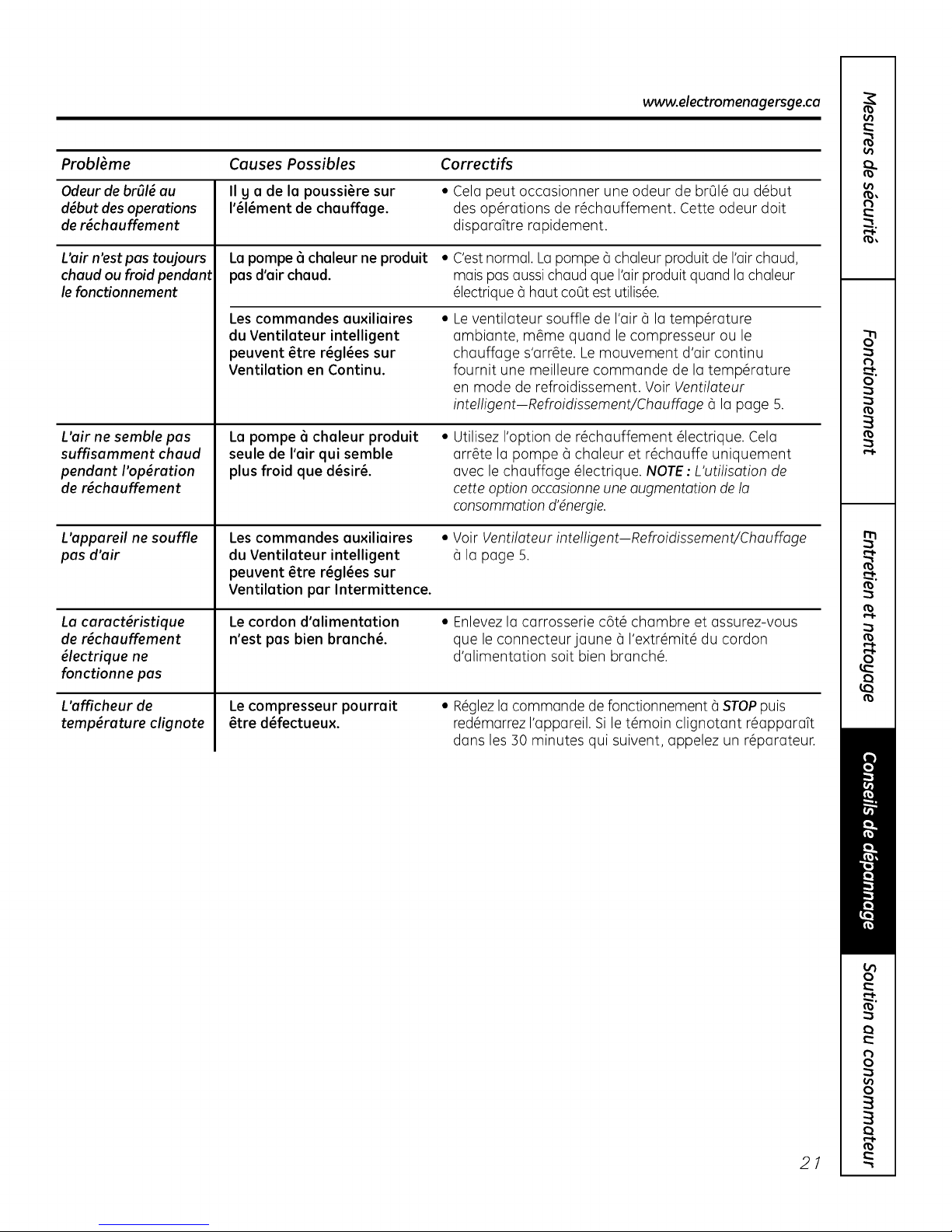
www.electromenagersge.ca
Probl_me Causes Possibles Correctifs
Odeur de brOl_au II g a de la poussi_re sur • Cela peut occasionner une odeur de brOl_ au d_but
d_butdes operations I'_l_ment de chauffage, des operations de r_chauffement. Cette odeur doit
de r_chauffement disparaTtre rapidement.
L'air n'est pas toujours La pompe 6 chaleur ne produit • C'estnormal. Lapompe 6 chaleur produit de I'airchaud,
chaud ou froid pendant pas d'air chaud, mais pasaussi chaud que I'airproduit quand la chaleur
le fonctionnement _lectrique 6 haut coot est utilis_e.
Les commandes auxiliaires
du Ventilateur intelligent
peuvent _tre r_gl_es sur
Ventilation en Continu.
Leventilateur soufle de I'air 6 la temperature
ambiante, m_me quand le compresseur ou le
chauffage s'arr_te. Le mouvement d'air continu
fournit une meilleure commande de la temperature
en mode de refroidissement. Voir Ventilateur
intelligent-Refroidissement/Chauffage 6 la page 5.
L'air ne semble pas
suffisamment chaud
pendant I'op_ration
de r_chauffement
L'appareil ne souffle
pas d'air
La caract_ristique
de r_chauffement
_lectrique ne
fonctionne pas
L'afficheur de
temperature clignote
La pompe 6 chaleur produit
seule de I'air qui semble
plus froid que d_sir&
Les commandes auxiliaires
du Ventilateur intelligent
peuvent _tre r_gl_es sur
Ventilation par Intermittence.
Le cordon d'alimentation
n'est pas bien branch&
Le compresseur pourrait
_tre d_fectueux.
Utilisez I'option de r_chauffement _lectrique. Cela
arr_te la pompe 6 chaleur et r_chauffe uniquement
avec le chauffage _lectrique. NOTE: L'utilisation de
cette option occasionneune augmentotion de la
consommotion d'@nergie.
• Voir Ventilateur intelligent-Refroidissement/Chouffoge
la page 5.
• Enlevezla carrosserie c6t_ chambre et assurez-vous
que le connecteurjaune _ I'extr_mit_ du cordon
d'alimentation soit bien branch&
• R_glezla commande de fonctionnement _ STOPpuis
red_marrez I'appareil. Si le t_moin clignotant r_apparaTt
dans les 30 minutes qui suivent, appelez un r_parateur.
21
Page 46

Cesbruits sont normaux.
Bruits normaux de fonctionnement
pI NG! POP!
"CLIC"
Vouspouvezentendre un pingcaus@par de I'eau
qui est ramass@eet envoy@econtre le condensateur
unjour pluvieuxou tr@shumide.Cettecaract@istique
diminue I'humidit@et am@lioreI'efficiencede I'appareil.
Vouspouvezentendre lesrelaiscliqueter quand les
commandes arr@tentet mettent en marche I'appareil,
ou s'ajustent pour changer latemp@ratureambiante.
DEGOUTTEMENT
6
OUIR!
DeI'eaus'amasseradansle plateau lesjours pluvieux
ou de grandehumidit4 L'eaupeutd@borderet couler
du c6t@ext@rieurde I'appareil.
Leventilateur int6rieurfonctionne continuellement
quand I'appareilfonctionne en mode de
refroidissement,_ moins que le commutateur de
ventilateursousla carrosseriec6t@chambre soit r@gl@
en cgcleventilateur (UP,vers le haut).Celofoit d@morrer
et arr@terleventilateur avec lecompresseur.Vous
pouvezaussientendre un bruit deventilateurquand il
s'arr@teetse met enmarche.
Vouspouveznoter un d@laide quelques minutes
quand vous essagezde remettre en marche votre
Zonelinetrop t6t apr@sI'avoirarr@t@ou si vous ajustez
le thermostatjuste apr_s I'arr@tdu compresseur.C'est
dO@un m@canismeint@gr@de protection du
compresseur en casde remiseen marche qui
occasionne un d@laide 3 minutes.
Pendantle cgcle de d@gel,leventilateur int_rieur et
le ventilateur ext_rieur s'arr_tent et le compresseur
fonctionne en mode de rafraTchissementpour d@geler
le serpentin ext_rieur.Apr@sced@gel,I'appareilse
remet en marche en mode dechauffage @lectrique
pour r_chauffer rapidement
la chambre @la temp@ratured@sir@e.
22
PROTECTION DU
COMPRESSEUR
Pourprot@gerlecompresseur et@viterdes arr@tset
des remisesen marche r@p@t@s,I'appareilest congu
pour fonctionner au moins 3 minutes apr@sla mise
en marche du compresseur @n'importe quel r@glage
de thermostat.
Page 47

Garantie Zoneline. www.electromenagersge.ca
Tout le service en vertu de la garantie est offert par nos centres
de service d'usine ou par un technicien outoris_ de Customer
Core®.Pour obtenir le service, contoctez Gordon Williams Corp.
ou 1.888.209.0999. Veuillez foumir le num_ro de s_rie et le
num_ro de module Iorsque vous oppelez pour obtenir le service.
Pour la pgriode de :
Un an
compter de la date
d'ochat oriqinal
Cinq ans
Acompter de la date
d'achat original
Cinq ans
A compter de la date
d'achat original
GE remplacera gratuitement :
Toute pigce du Zoneline pr_sentant un d_faut dO au materi_l ou _ Io main-d'oeuvre.
Au cours de cette garantie limit_e d'un an, GEcouvrira gratuitement les frais de main
d'oeuvre et de service connexe pour le remplocement de Io piece ddectueuse.
Toute pigce du sgstgme scell_ de r_frig_ration (compresseur, condenseur, evaporateur et
tugouterie) pr_sentant un d_faut dOau materi_l ou _ Io main-d'oeuvre. Au cours de cette
garantie limit_e additionnelle de quatre ans, GEcouvrira gratuitement les frais de main
d'oeuvreetde service connexe pour leremplocement de Io pieceddectueuse.
Dela deu×i_me 6 la cinqui_me annie depuis I(_date d'achot original,GEremplocera certuines
pi_ces qui pr_sentant un ddaut dOau materi_lou _ Iomain-d'oeuvre. Lespi_ces couvertes sont
lesmoteurs deventiloteur, lescommutateurs, lesthermostats, le chouffage, lesprotecteurs
de chouffage, I(_surcharge de compresseur,les sol_noides, lescartes de circuit imprim_, les
thermistances, lescommandes de gel,Io pompe ICR,lescondensateurs,lesvarioteurs et
le roulement_ billede Iosouffleuse int_rieure. Pendantcette garantie limit_e additionnelle
de quatre ans, vous serezde tousles frais de main-d'oeuvre et de serviceconnexe.
Ce qui n'est pas couvert :
• Toute visite 6 votre site pour vous expliquer le
fonctionnement de I'appareil.
• Une installation, livraison ou entretien inadequate.
Sivous avez un probl_me d'installation, ou si
I'appareil de conditionnement d'air ne rafraTchit pas
suffisamment 6 votre go0t, appelez votre revendeur ou
votre installateur. Vous _tes responsable de fournir une
installation adequate de branchement _lectrique.
•Dans des Iocaux commerciaux, la main-d'oeuvre
n_cessaire pour transporter I'appareil jusqu'6 un
emplacement o5 il peut _tre r_par_ ou entretenu par
un technicien qualifi_.
• Toute panne ou tout dommage occasionn_ par la
corrosion due 6 I'installation ou 6 un milieu contenant
des produit chimiques corrosifs.
• Leremplacement des fusibles ou le r_enclenchement
des disjoncteurs.
Agrafez le re_u d'achat ici.
Pour obtenir le service sous
garantie, vous devrez fournir
la preuve de l'achat original.
Toute panne de I'appareil r_sultant de modifications
6 I'appareil ou occasionn_e par une utilisation non
raisonnable, en particulier un manquement de fournir
un entretien raisonnable et n_cessaire.
• Toute panne ou dommage r_sultant d'une corrosion
due 6 une installation 6 proximit_ de lamer, sauf s'il
s'agit d'un module trait_ 6 I'usine contre la corrosion,
comme I'indique son num_ro de module.
• Tout dommage au produit attribuable 6voltage
impropre d'alimentation _lectrique, un accident, un
incendie, une inondation ou un cas de force majeure.
• Tout dommage direct ou indirect 6 la propri_t_
priv_e caus_ en raison d'une d_fectuosit_
_ventuelle de cet appareil.
• Tout dommage subi apr_s livraison.
• Leservice s'il est impossible d'avoir acc_s au produit
pour ce faire.
EXCLUSIONDE GARANTIESIMPLICITES- Votre seul et unique recours est la r_paration du produit selon les
dispositions de cette Garantie fimit_e. Touteslesgaranties implicites, incluant lesgaranties de commerciafit_ et
d'ad_quation 6 un usage sp_cifique, sont fimit_es 6 une annie ou 6 la p_riode la plus courte autoris_e par la
I_gislation.
Cette gorontie couvre I'ocheteur original et tout possesseur subsequent de produits ochet_s pour un usage
ou Canada. Si le produit est instoll_ dons une r_gion o3 ne se trouve oucun r_poroteur outoris_ GE,vous devrez
peut-_tre ossumer les frois de transport ou opporter exp_dier le produit 6 un centre de service outoris_ GE.
Certaines provinces nepermettent pos I'exclusion ou Io limitation des dommoges indirects ou cons4cutifs et, par
consequent, I'exclusion ci-dessus peut ne pos s'oppliquer 6 vous. Cette gorontie vous donne des droits juridiques
porticuliers et vous pouvez _golement ovoir d'outres droits qui vorient d'une province 6 I'outre. Pour conno[tre vos
droits juridiques dons votre province, consultez votre bureau local ou provincial de protection des consommoteurs.
Garant : General Electric Compang. Louisville, KY 40225 23
II
Page 48

Soutien au consommateur.
Vousavezune questionou vousavez besoin d'aidepour votre appareil _lectrom_nager? Contactez-nous par
l Site Web appareils @lectrom@nagers GE www.electromenagersge.ca
Internet au site www.electromenagersge.ca 2/4heuresparjour, tous lesjours de I'ann@e.
Servicede r@parations
Servicede r@parationsGEesttout pr@sde vous.
Pourfaire r@parervotre @lectrom@nagerGE,il suffit de nous t_l@phoner.
1.800.561.3344
Studio de conception r@oliste
Sur demande, GEpeut fournir unebrochure sur I'am_nagement d'une cuisinepour lespersonnes
mobilit_ r_duite.
Ecrivez: Directeur,Relationsavec lesconsommateurs, Habe Canada Inc.
Bureau310,1 Factory Lane
Moncton,N.B.EIC 9M3
Pi@ceset accessoires
Ceuxqui d@sirentr@parereux-m@mesleurs@lectrom@nagerspeuvent recevoir pi@ceset accessoires
directement @lamaison (cartesVISA,MasterCardet Discoveraccept_es).
Lesdirectives stipul_es clans lepresent manuel peuvent _tre effectu_es par n'importe quel utilisateur. Les
autres r_parations doivent g_n_ralement _tre effectu_es par un technicien qualifi& Soyezprudent, car
une r_paration inadequate peut affecter le fonctionnement s_curitaire de I'appareiL
Voustrouverezdans lespagesjaunes de votre annuaire le num@rodu Centrede service Mabe le plus proche.
Autrement, appelez-nous au 1.800.661.1616.
Contactez-nous
Sivous n'@tespas satisfait du serviceapr@s-ventedont vous avez b@n@fici@:
Premi_rement, communiquez avec lesgens qui ont r_par_ votre appareil.
Ensuite, sivous n'_testoujours pas satisfait envoyez tousles d@tails-num@rode t_l@phonecompris-au
Directeur,Relationsavec lesconsommateurs, Mabe Canada Inc.
Bureau310,1 FactoryLane
Moncton, N.B.E1C9M3
Inscrivez votre apporeil _lectrom_noger en direct, eussit6t qua possible. Celaam_liorera nos
lnscrivez votre opporeil @lectrom@noger
communications et notre service apr_s-vente.Vous pouvez_galement nous envoyer par la poste
le formulaire d'inscriptionjoint _ votre documentation.
24
Page 49

GEAppliances.com
@
0
N
Om
0
Instrucciones de seguridad ............ 2
Instrucciones de operaci6n
C6rno retirar el gabinete del ambiente ...... 4
Control de ventilaci6n .................... 4
Controles ................................ 3
Controles au×iliares .................... 5-8
Direcci6n del aire ........................ 4
Cuidado g limpieza
Bandeja de la base ....................... 9
Filtro de ventilaci6n ...................... 9
Filtros de aire ........................... 10
Gabinete del ambiente g montante ....... 9
Serpentinas externas ..................... 9
Instrucciones de instalaci6n
Conexi6n el_ctrica .................. 13-16
_LDeseacambiar una unidad
ga instalada? ........................... 12
Instalaci6n del acondicionador
de aire Zoneline ..................... 17, 18
Kit de drenaje opcional .................. 19
Preparaci6n ............................ 11
Modelo de refmscar/
calentar 4100
Modelo de bomba
de calor 6100
Om
Om
0
0
U
Solucionar problemas .......... 20,21
Sonidos normales de operaci6n ......... 22
Soporte al consumidor
Garantia ................................ 23
Soporte al consumidor ................... 24
Escriba los n6meros de modelo
g serie aqui:
# de Modelo
# de Serie
EstosnOmerosse encuentran en una
etiqueta ubicada detrds del gabinete
del ambiente sobre la bandeja de
la base.
TINSEA576JBRZ 49-7612-1S 07-09 JR
Page 50

INFORMACION IMPORTANTEDESEGURIDAD.
LEATODASLAS INSTRUCCIONESANTESDE USAR.
iADVERTENCIA!
Par su seguridad, se debe seguir la informaci6n en este manual para minimizar el riesgo
de incendio o explosion, descargas el4ctricas, o pare evitar dahos a la propiedad, lesiones
personales, o la muerte.
PRECAUCIONESDE SEGURIDAD
Antes de iniciar su usa, el acondicionador
de aire Zoneline debe instalarse
correctamente segOn los Instrucciones
de instalaci6n. Ver los Instrucciones de
instalaci6n en la porte trasera de este
manual.
Reemplace inmediatamente todos los
cables el@ctricos que se hogan pelado
o que se hogan daBado de alguna otra
manera. Un cable de corriente daBado
no debe repararse, sino que debe ser
sustituido par uno nuevo que se adquiera
del fabricante. No use un cable el@ctrico
que muestre evidencias de deterioro, o
daBos de abrasi6n en su superficie en
alguno de sus extremos.
Desenchufe o desconecte el Zoneline
desde la caja de fusibles o el disguntor
antes de realizar cualquier tipo de
reparaci6n.
NOTA" Recomendamos en@gicamente que
cualquier servicio Ilevado a cabo en este
equipo Io realice un individuo calificado.
• Los sistemas de acondicionador de aire
R410A requieren que los contratistas g
t@cnicos utilicen herramientas,
equipamiento g normas de seguridad
aprobadas para su usa con este
refrigerante. NO utilice equipomiento
certificedo s61o peru refrigerente R22.
_Desea reemplazar una unidad ya
instalada?
Para m6s detalles, ver las Instrucciones
de instalaci6n en este manual.
LEA YSIGA ESTASINSTRUCCIONESDE SEGURIDAD
CUIDADOSAMENTE.
GUARDE ESTASINSTRUCCIONES
2
Page 51

Sobreloscontroles delZoneline.
TEMP
CONTROLDE
TEMPERATURA
Controles
Control de temperatura
0
Elcontroldetemperaturaseusaparamantenerla
temperaturaambiente.Elcompresorseencender6
gapagar6paramantenerlahabitaci6nalmismo
niveldecomodidad.
Pulseelbat6nA parasubirlatemperatura.
Pulseelbat6nV parabajarlatemperatura.
NOT_ Lapantallamuestralatemperaturaconfigurada,
nolatemperaturaambiente.
Suspensi6n
0
Pulseparaconfigurarelacondicionadordeairepara
quefuncionedurante8 horasantesdequevuelva
autom6ticamentea laconfiguraci6nanterior.
Cuandoest_enelmodo deenfriamientogseactive
elapagadoautom6tico,latemperaturaestablecida
aumentar6autom6ticamente2°F(-I,I°C)despu6sde
lasegundahorag luegoI°F(-0,6°C)cada
horadurantelasdoshorassiguientes.Adem6s,
lavelocidaddelventiladorcambiar6alenta.Cuando
est6enelmodo decalefacci6n,latemperatura
establecidabajar6delamismamanera.
Paracancelarelapagado autom6tico,pulseelbot6n
MODE o elbat6nSLEEPatravez.
! HiGH
LOW
AUTO
===,COOL
_=, FAN
HEAT
m !
FAN MODE SLEEPOPERATION
OPERACIONDEVENTILADOR,
MODOY SUSPENSION
O
Control d.e,Iventilador, modo
O
y operaclon
FAN-Establecela operaci6ndelventilador
alavetocidadALTA(HIGH),BAJA(LOW)o
AUTOMATICA(AUTO).CuandoseponeenAUTO,
secambiaautomdticamenteentreLOWgHIGH
seg0ncambielatemperaturaambiente,
MODO-COOL-Paraenfriamiento
FAN-Parala operaci6ndet
ventilador0nicamente
HEAT-Paracalefacci6n
OPERATION-ON/STOP(ENCENDIDO/DETENER)-
Enciendeoapagalaunidad.Laelectricidadpermanece
conectadaalZoneline.LascaracteristicasdeFreeze/
HeatSentinel(monitordecongelamiento/calor)siguen
funcionandosiseencuentraactivo.Consultelasecci6n
deMonitordecongelaci6n/Monitordecolorde lapdgina6.
NOTA:Elvisuolizodorde Iotemperoturomostrord
unoluzintermitenteporoindicorunoposiblefolio
deIounidod.Estoblezcoelcontroldeoperoci6n
enSTOP(detener)g luegoendendodenuevoIo
unidod.SiIoluzintermitenteoporecedenuevoen
menosde30 minutos,Ilameparasolicitorservicio.
Recuperaci6nr6pida de calor
SeactivacadavezquesecambiaettermostatodetmodoSTOP
(apagado)oCOOL(frio)almodoHEAT(cator).Loscatefactores
et6ctricosseactivanhastaquesehagaatcanzadoetpuntodefinido
dettermostato.Enlosmodetoscon bombadecalor,laoperaci6nde
estabombacontinuar6enlasiguienteaativaci6ndecalor.
Sobre la bomba de calor ($61oserie 6100)
Sepuede ahorrardinero medianteel usode lasbombas
decalor,ga que toman elcalordelaire exterior-induso
cuando la temperatura externase encuentrapordebajodel
punto de congelaci6n-g Ioliberandentro de la habitaci6n.
Afin deobtener el mejordesempehodesu bomba
decalor,no modifique eltermostato ambiental mug
a menudo.Sielevala configuraci6ndecalor en 2-3 grados,
elZonelinecomenzar6 a utilizarsuselementosel6ctricosde
calentamientopara alcanzarr6pidamentelanueva
configuraci6nde temperatura.
Paraprevenirun encendidoy apagadoinmediato,
elcompresorsetoma un minimodetresminutos
paracambiaracualquierconfiguraci6n.
Elmotor deventilaci6nintema comienzaafuncionar antes
queel compresorg se detienedespu6sde que 6steOltimo
sehaga apagado.
Cuandola temperatura exterior es inferior a 25°F(-3,8°C),
elaireacondicionadorecibeel calordelcalentador el6ctrico
envezde hacerlodesde la bomba de calor.
Loselementosel6ctricosde calentamientoutilizan
mucha m6selectricidadque lasbombas decalor,
y su operaci6nresultam6s costosa. 3
Page 52

Otras caracteristicas del Zoneline.
Control de ventilaci6n
NOTA:Antes de comenzar a utilizar el aparato,
deben retirorse dos tomillos de empaque de la
puerto de ventilaci6n. Ver los Instrucciones de
instalaci6n en la porte trosero del manual. Si usted
no planea utilizar la corocteEstica de ventilacidn,
deje estos dos tomillos en su lugar.
Lo palonco de control de ventiloci6n seencuentra
sabreel lade izquierdo media deIo unidad
Zoneline,detr6s del gobinete del ombiente.
CuandoseIoconfigure enposici6ncerrodo,s61o
circula gse filtra elaire dentro de la habitaci6n.
Cuando seIoconfigure en posici6n abierta,
sepermite el ingreso de oire externo o la
hobitoci6n. Estoreducir6 la eficiencia pare calentar
o enfriar el ambiente.
consejo de ahorro de energia: Montengo el
dispositivo de control en Ioposici6n cerrodo. De ese
mode, el aire dentro del ambiente circular6 g podr6
filtrarse.
C6mo retirar el gabinete del ambiente
Existencontroles adicionales ubicados detr6s
del gabinete del ambiente.
Pare retirar: Jale de laparte inferior para
desengancharlo de las pesta_as(1).Luego
empOjelohacia arriba (2).
Posici6n
abierta
Posici6n
cerrada
l
\
Controlde
ventilaciOn
(ubicadoenla
posiciOnmedia)
Pare volvera colocar:Coloque las pestaBassabre
el rielsuperior (1).Presionehacia adentro desde la
parte inferior haste qua encajeen su lugar (2).
_ uitelostornillos
deembalaje
(sisedesea
laoperaci6n)
Direcci6n del aire
Pare cambiar ladirecci6n delaire,retire elgabinete
del ambiente. Quite los7 tornillosque sostienenla
rejilla de ventilaci6n ensu lugar.Girela rejilla en
180°,vuelva a colocar los tornillos g el gabinete.
4
Pare cambiar to direcciSndet aire,retire elgabinete
detambiente _Igireto reiitta en 180°.
Tornillosdelarejilla
Posici6n
predeterminada
Tornillosdelarejilla
Page 53

Controlesauxiliares delZoneline. 6EAppliances.com
[ MODE 1
Controles auxiliares--Bot6n de configuraciones auxiliares
BotGndeconfiguracionesauxiliares
Loscontroles de configuraciones auxiliares se
encuentran detrGs del gabinete del ambiente,
debajo del panel de control.
Retireel gabinete del ambiente. Ver la secciGn
Camo retirar e!gabinete de! ambiente.
Elpropietario es responsable de garantizar que
los controles auxiliares se encuentren configurados
en la funci6n deseada. Hag 9 modos diferentes
que pueden configurarse utilizando el bot6n
de configuraciones auxiliares. Para cambiar
los modos, presione AUX SET(aparecer6 "AU"
en la pantalla), Presione el bot6n de modo sobre
la almohadilla de control una determinada cantidad
de veces (indicada en elprimer digito de la pantalla) g
siga con la flecha ascendente o descendente (indicada
en el segundo digito de la pantalla) para realizar una
selecci6n. Presioneel bot6n AUX SETpara confirmar
laselecci6n.
R First Digit b I Second Digit
Press "Mode" Press _. / Y
I Smart Fa_ COOL...... C_ -- Cycle _ -- Co{it{riM e
B Load
Shedding L,J - off b'_ _ on
Sentinel HEAT
i Constant _ 0 60F-85F 0 60F-65F
Fan _ 1: 64F-85F 1: 60FWOF
Temperature d 2: 66F-85F 2: 60FW2F
Lmit _HEAT _ 3: 67F-85F 3: 60FW4F
Class 2Mode 5; 72F-85F 60F-78F
bwt Duct Mode 7: 76F-85F 60F-85F
1
g All 12R Mode
(AZ61 Only)
Boost Heat
(AZ61 Onmy)
u
coo
coo
a_ - Off -
COOL HEAT
4: 70F-85F 60F°76F
6; 74F-85F 60F-80F
Ventilador inteligente--Reffigeraci6n/Calefacci6n
LaconfiguraciGnpredeterminadaparaelModoi l -- HIGH(atta_
eslasiguiente: _L_ -- LOW(baja)
Reffigeraci6n:Continua(ON)(encendido) -- AUTO(autom_tico)
Calefacci6n:Ciclo(OFF)(apagado) RefrigeraciGn- Ciclo
PresioneMODE(modo)hastaqueaparezcaun i enel
primerdigitodelapantallaparaelmododereffigeraci6n
SmartFan(ventiladorinteligente).LaluzLEDCOOL(ffio)
delcontrolprincipalestar6encendida.Paracambiaral
mododecalefacci6n,presioneMODEdenuevo.Laluz
LEDHEAT(calor)delcontrolprincipalestar6encendida.
Presionelaflechadescendenteparaconfigurarel
encendidogapagadodelventiladorinternocuando
la unidadseencuentrecalentandoo enffiando"u".
Presionelaflechaascendenteparaconfigurarqueel
ventiladorinteriorfuncionecontinuamente"n". Esto
puedeverseenelsegundodigitodelapantalla.Presione
AUXSET(configuracionesauxiliares)paraconfirmarsu
selecci6ngsalirdelmodoAUXSET,o presioneMODE
paracontinuarconlaconfiguraci6ndeotrasfunciones.
RefrigeraciGn - Continua
CalefacciGn- Ciclo
If j!_ -- LOW(baja) -- FAN(ventilador)
CalefacciGn - Continua
-- HIGH(atta) m COOL(fifo)
b'_ -- LOW(baja) -- FAN(ventilador)
-- AUTO(autom_tico) -- HEAT(cator)
-- HIGH(atta) -- COOL(fifo)
-- LOW(baja) -- FAN(ventilador)
L,J -- AUTO(autom_tico) m HEAT(cator)
-- HIGH(atta) -- COOL(fifo)
-- AUTO(autom_tico) m HEAT(cator)
Tapa de acces0
On
m COOL(fifo)
-- FAN(ventitador)
-- HEAT(calor)
[ MODE 2
Desconexi6n decarga (Controlcentral)
Laconfiguraci6npredeterminadaparaelModo 2
esOFF (apagado).
Estacaracteristicaest6activas61osila unidadseencuentra
enelmodoCDC.PresioneMODE(modo)hastaque
aparezcaun2enelprimerdigitodelapantallaparael
modoLoadShedding(desconexi6ndecarga).Presione
laflechadescendenteparaOFF(apagado)"u"o laflecha
ascendenteparaON(encendido)"n".Estopuedeverse
enelsegundodigitodelapantalla.Cuandoestemodo
est6activado,elventiladorinteriorpuedeencenderse(ON)
oapagarse(OFF)medianteloscontrolesdelaunidad.
Cuandoestemodoest6apagado,elbot6ndelventiladorse
encuentradesactivado.PresionAUXSET(configuraciones
auxiliares)paraconfirmarsuselecci6ngsalirdelmodo
AUXSET,o presioneMODE(modo)paracontinuarcon
laconfiguraci6ndeotrasfunciones.Laconfiguraci6n
predeterminadaparaelModo2esOFF(apagado).
Eu E
Desconexi6nde Desconexi6nde
cargaapagada cargaencendida
(OFF) (ON)
5
Page 54

Controles auxiliares delZoneline.
I MODE31
IMODE 41
Monitor de congelaci6n/Monitor de calor
EnlaconfiguraciGnpredeterminadaparaelHodo3,HeatSentinel(monitorde
calor)seencuentradesactivadoperoFreezeSentinel(monitordecongelaciGn)
seencuentraactivado.
PresioneMODE(modo)hastaqueaparezcaun3enelprimerdigitodelapantalla
paraelmodoFreezeSentinel(monitordecongelaciGn).LaluzLEDCOOL(frio)
delcontrolprincipalestar6encendida.PresioneMODEdenuevoparacambiar
aHeatSentinel(monitordecalor).LahzLEDHEAT(calor)delcontrolprincipal
estar6encendida.PresionelaflechadescendenteparaOFF(apagado)"U" o
laflechaascendenteparaON(encendido)"l--r'.Estopuedeverseenelsegundo
digitodelapantalla.PresioneAUXSET(configuracionesauxiliares)paraconfirmar
suselecciGnysalirdelmodoAUXSET,o presioneMODE(modo)paracontinuar
conlaconfiguraciGndeotrasfunciones.
CuandoseactivaFreezeSentinel(monitordecongelaciGn),seliberacalor
automGticamentesinunainterfazdeusuario.Estoayudaa evitardaflosen
lascafleriasalencender(ON)lacalefacciGnyelventiladorinteriora41°Fy
alapagarla(OFF)a 46%.
CuandoseactivaHeatSentinel(monitordecalor),seliberafrioautomGticamentesin
unainterfazdeusuario.Estoayudaa evitarunacalefacciGnexcesivaalencender
(ON)elacondicionadordeairea85%(30°C)yapagarlo(OFF)a80°F(27°C).
NOTA:Estasfuncionesseactivancuandolaunidadseenchufa,aOnsise
encuentraenlaposiciGnSTOP(parar).
Ventilador encendido constante
Laconfiguraci6npredeterminadaparaelHodo4esOFF(apagado).
PresioneMODE(modo)hastaqueaparezca4enelprimerdigtodelapantalla
paraconfigurarelventiladorenfuncionamientocontinuoaaltavelocidad,a0nsi
launidadseencuentraenlaposici6nSTOP(parar).Presionelaflechadescendente
paraOFF(apagado)"U"olaflechaascendenteparaON(encendido)"1--1."
Estopuedeverseenelsegundodigitodelapantalla.PresioneAUXSET
(configuracionesau×iliares)paraconfirmarsuselecci6nysalirdelmodoAUXSET.
opresioneMODE(modo)paracontinuarconlaconfiguraci6ndeotrasfunciones.
HIGH(atta) /
--'_ L{ -- LOW(baja)
Monitorde congelaciGnapagado(OFF)
-- AUTO(autom_tico)
HIGH(atta) /
_! h_ -- L0W(baja)
_'_ -- AUTO(autorn_tico)
Monitorde congelaciGnencendido(ON)
-- HIGH(atta) -- COOL(frio)
m_'_L{ -- LOW(baja) -- FAN(ventilador)
Monitor de calor apagado (OFF)
Monitor de calor encendido (ON)
-- AUTO(autom_tico) _ HEAT(calor)
-- HIGH(atta) -- COOL(if[o)
_"_ LOW(baja) -- FAN(ventilador)
-- AUTO(autom_tico) _ HEAT(calor)
Ventilador Ventilador
constante constante
apagado(OFF) encendido(ON)
COOL(frio)
-- FAN(ventilador)
-- HEAT(calor)
COOL(frio)
-- FAN(ventilador)
-- HEAT(calor)
IMODE51
IMODE 61
6
Limitaci6n de temperatura
Laconfiguraci6npredeterminoadaparaelHodo5eslasiguiente:
Frio:0(60°F[15C]a85%[S0C])
Calor:7(60°F[15°C]a 85°F[30°C])
PresioneMODE(modo)hastaqueaparezcaunSenelprimerdigitodelapantalla
paraelmododerefrigeraci6nTemperatureLimiting(limitaci6ndetemperatura/.
LahzLEDCOOL(frio/delcontrolprincipalestar6encendida.Paracambiaral
modocalor,presioneMODE(modo)denuevogseencender6lahzLEDHEAT
(calor)delcontrolprincipal.Paraconfigurarloslimitesdetemperatura,presione
lasflechasascendentesodescendentes.Elsegundodigitodelapantallase
hallarcientre0 y7dependiendodellimiteque@seaconfigura,Latablaseflala
loslimitesdisponibles.PresioneAUXSET(configuracionesauxiliares)para
confirmarsuselecci6nysalirdelmodoAUXSET.opresioneMODE(modal
_aracontinuarconlaconfiguraci6ndeotrasfunciones.
Limitesde temperatura- Frio
O=6O°Fa 85°F(15°Ca 30°C)
1=64°Fa 85°F(18°Ca 3O°C)
2 =66°Fa 85°F(19°Ca3O°C)
3 =68°Fa 85°F(2O°Ca 3O°C)
4 =7O°Fa 85°F(21°Ca 3O°C)
5 =72°Fa 85°F(22°Ca3O°C)
6 =74°Fa 85°F(23°Ca3O°C)
7 =76°Fa 85°F(24°Ca3O°C)
Limitesde temperatura- Calor
O= 6O°Fa65°F(15°Ca 18°C)
1= 6O°Fa7O°F(15°Ca21°C)
2= 6O°Fa72°F(15°C a22°C)
3= 6O°Fa74°F(15°Ca23°C)
4= 6O°Fa76°F(15°Ca24°C)
5= 6O°Fa78°F(15°C a26°C)
6= 6O°Fa80°F(15°C a27°C)
7= 6O°Fa85°F(15°C a3O°C)
Termostato remoto--Clase 2
Laconfiguraci6npredeterminadaparaelHodo6esOFF(apagado).
AIconfigurarestemodoenON(encendido).launidadpuedefuncionarcon
untermostatodepareda controlremotodeClase2.PresioneMODE(modo)
hastaqueaparezcaun6enelprimerdigitodelapantallaparaelmodoClass2
(clase2).Presionelaflechadescendenteparaapagar(OFF)laopci6n"U."
Presionelaflechaascendenteparaencender(ON)laopci6n1--1".Estopuede
verseenelsegundodigitodelapantalla.PresioneAUXSET(configuraciones
auxiliares)paraconfirmarsuselecci6nysalirdelmodoAUXSET.opresione
MODE(modo)paracontinuarconlaconfiguraci6ndeotrasfunciones.
w w HIGH(alta) 1 COOL(fifo)
C ,_t -- LOW(baja) -- FAN(ventilador)
_ _ -- AUTO(autom_tico)-- HEAT(calor)
LimitaciGn de temperatura Ffio - L[mite 2
w. _,_ HIGH(alta) COOL(fifo)
Zt -- LOW(baja) -- FAN(ventilador)
_ _ -- AUTO(autom_tico) 1 HEAT(calor)
LimitaciGn de temperatura Calor - L[mite 3
C Cn
clu c{
Clase2 Clase2
apagado(OFF) encendido(ON)
Page 55

MODE 7
[
Modo poro conductos
Laconfiguraci6npredeterminadaparaeltodo 7esOFF(apagado).
Estaconfiguraci6nseutilizacuandolaunidadseinstalautilizando
unkitdeadaptadordeconductos.Silaunidadest6instaladacon
conductos,elHoctoparaconductos(DuctMode)debeconfigurarse
enencendido(ON).Estoaumentalavelocidaddelventiladorpara
garantizarunacirculaci6nadecuada.
PresioneMOBE(modo)hastaqueun7aparezcaenelprimerdigito
delapantalla.Presionelasflechasascendenteo descendentepara
configuraresteinterruptorenapagado(OFF)"U"oenencendido
(ON)"N". Estopuedeverseenelsegundodigitodelapantalla.
PresioneAUXSET(configuracionesauxiliares)paraconfirmarsu
selecci6nysalirdelmodoAUXSET.
GEAppliances.com
ParaelModeloAZ6100,presioneMODE(modo)paracontinuarcon
laconfiguraci6ndeotrasfunciones.AIpresionarMOBEenelModelo
AZ4100,sevolver6almodoAUXSETy"AU"aparecer6enlapantalla.
n nn
lu !
Modopara Modopara
conductos conductos
apagado(OFF) encendido(ON)
[MODE81
MODE 9
[
Color todo el_.ctrico (s61oAZ6100)
Laconfiguraci6npredeterminadaparaelModo8esOFF(apagado).
Estaopci6ndecalorel@ctricos61ofuncionaenelmodelo6100.
Cuandoestaopci6nseencuentraactivada(ON)"N", seanulael
funcionamientoconbombadecalor,potIoquelaunidads61oofrece
calorpotresistenciael_ctrica.
Paraconfigurarlaopci6nAll-ElectricHeat(colortodoeldctrico),
presioneMODE(modo)hastaqueaparezcaun8enelprimerdigito
delapantalla.Presionelasflechasascendenteodescendentepara
configuraresteinterruptorenapagado(OFF)"U"o enencendido(ON)
"PI". Estopuedeverseenelsegundodigitodelapantalla.
Impulso de color (s61o AZ6100)
Laconfiguraci6npredeterminadaparaelivlodo9esOFF(apagado).
CuandoHeatBoost(impulsodecalor)seencuentraactivado(ON)y
lastemperaturasexternasseencuentranentre2S°Fy 46°F,seanula
elfuncionamientodes61obombadecalonEstaconfiguraci6nse
utilizaparaofrecercalorcomplementarioalfuncionamientode
bombadecalormediantecalorpotresistenciael_ctricaen
condicionesenlasqueelfuncionamientodes61obombadecalorno
essuficienteparamantenerunatemperaturaambientecongruente
yconfortable.NOTA:Laopci6ndeImpulsodecalornodebeutilizarse
conelfuncionamientodetermostatoremoto.Estoprovocar6quela
unidadcambieacalorpotresistenciacuandolatemperaturaexterior
seade46°F.
Controles uuxiliures--Conexiones terminules
Loscontrolesauxiliaresest6nubicadosdetr6sdelgabinete
delambientepordebajodelatapadeacceso.
_] Apagueydesenchufelaunidad.
F_-IRetireelgabinetedelambiente.Vetlasecci6nC6moretiror
elgobinetedelombiente.
[j] Ouiteeltornillodelatapadeacceso.
r-4-1Parahacerconexionesel#ctricas,inserteloscablesenlaparte
inferiordelasterminalesyajustebienlostomillos.
r-5--1Despu&sderealizartodaslasconexionesdeseadas,vuelva
acolocarlatapadeaccesoyelgabinetedelambiente.
PresioneAUXSET(configuracionesauxiliares)paraconfirmarsu
selecci6nysalirdelmodoAUXSET,opresioneMOBEparacontinuar
conlaconfiguraci6ndeotrasfunciones.
O on
ElU E!
Colortodo Colortodo
el6ctrico el6ctrico
apagado(OFF) encendido(ON)
ParaconfigurarImpulsodecalor,presioneMODE(modo)hastaque
aparezcaun9enelprimerdigitodelapantalla.Presionelasflechas
ascendenteo descendenteparaconfiguraresteinterruptoren
apagado(OFF)"U" oenencendido(ON)"n". Estopuedeverseen
elsegundodigitodelapantalla.PresioneAUXSET(configuraciones
auxiliares)paraconfirmarsuselecci6nysalirdelmodoAUXSET.
O
JU Zt
Impulsode calor Impulsode calor
apagado (OFF) encendido (ON)
Elpropietarioesresponsablederealizartodaslasconexionesy
configurarelmodoapropiadodeAUXSET(configuracionesauxiliares).
PRECAUCI( N:
Unaconexi6nel_ctricaincorrectapuededaflarlasparteselectr6nicas
desuZoneline.Nosepermitelaconexi6nsimult6neadevarias
unidadesenunmismocable.Estopuedeprovocardaflosogenerar
unfuncionamientoerr@ico.Debeutilizarseuncablediferentedesde
cadainterruptordecontrolhaciacadaZoneline.
gade
acceso
Ventitadorexterno___J --
Controldeescritoriocentral--
LComun
I_ Blanco- Calentador
--Amarillo - Compresor
Negro- Solenoide(s61oAZ61)
Verde- Ventilador velocidadalta
Verde- Ventilador velocidadbaja
Rojo- $61o24V AC
7
Page 56

Controles auxiliares delZoneline.
Ventilador externo (disponible en forma local)
Una vezque se Io conecta, un ventilador au×iliar
o externo puedecontrolarse con el motor de ventilaci6n
interno de Zoneline.Lasconexiones brindan 2a voltios
de CApara suministrar energ[a a un circuito intermedio,
Ioque enciendeel ventilador externo.
Control central
Unavezquese laconecta,launidadpuedeencenderse
o apagarsemedianteunateclaubicadaenel panel
centraldecontrol.Debeutilizarseuncablediferente
desdecadainterruptordecontrolhaciacada
acondicionadordeaireZoneline.
Paraopcionesdeconfiguraci6ndeventilador,consulteel
MODO2enla p6gina5.
Termostato remoto
Cuandoseconectaauntermostatoremoto,elsensorde
temperaturainteriorcambiade launidadaltermostato
remoto.Porestaraz6n,lasunidadesfuncionar6ncon
ciertasdiferenciascuandoseconectanauntermostato
remoto.Lasiguientetablaindicaelfuncionamientode
launidadcuandoseconectaa untermostatoremoto.
NOTA: Laconfiguraci6nde ModoClase2(Modo6)debe
configurarseenencendido(ON)"n" paraquelaunidad
funcioneconuntermostatode paredremotoClase2.
(Verlasinstruccionesdeinstalaci6nincluidascon las
instruccionesdeltermostatoremotogde Mododela
p6gina7).
_r_
I°!°°° °°!°°°lq
:
LiJJ -- F-
f
Ventilador externo _"
I IJ01I°1 11
L_J
Controlde escritoriocentral _
1@l®1®l®l®l®1 1
J I I01I
Rojo- s61o24V AC _" _"
Verde- Ventiladorvelocidadbaja --J
Verde- Ventilador velocidadalta --
Negro- Solenoide
Amarillo- Compresor
Blanco- Calentador
Corn[in
J
Semuestra
encendido(ON)
IMPORTANTE:Lasconexionesdel
termostatodeZonelineproveens61o2/4voltiosdeCA.
Siutilizauntermostatodepareddigital/electr6nico,
@stedebeconfigurarsea 2/4voltiosdeCA.Verlas
Instruccionesdeinstalaci6nparaeltermostatodepared.
Caracteristica Bombade calor Calorelectrico
Controlde escarcha interno Si Si
Monitor de congelaci6n Si Si
Velocidad de ventitador autom_tica No No
Limitaci6nde temperaturaelectr6nica No No
Cambioa cator por resistencia en Determinado por N/A
basea la temperatura interior el termostato remoto
Cambioa cator por resistencia en Si N/A
basea la temperatura exterior
Descongelaci6n de cicto inverso Si N/A
Calor por resistencia simult_neo No N/A
con bomba de calor
Bloqueode calor por resistencia Si N/A
Ciclode ventilador "Smart Fan" Ventilador configurado en 0N/AUT0 Ventitador configurado en 0N/AUT0
(ventitador inteligente} (encendido/autom_tico) (encendido/autom_tico)
8
Controlde escritorio central Si Si
entermostato remoto en termostato remoto
_k PRECAUCION:
Unasconexionesinadecuadaspueden provocarda_os
altermostatodeparedo a lasparteselectr6nicasde
Zoneline.Debeprestarseespecialcuidadodurantela
conexi6ndeloscables.Nodebenrealizarseconexiones
delineaconningOncircuito.Todosloscablesdeledificio
debenaislarsedela lineadetensi6n.
Page 57

Cuidadog limpieza. GEAppliances.com
Gabinete del ambiente g montante
Apague el Zoneliney desconecte el suministro
de energfa.
Serpentinas externas
Lasserpentinas dela zona externa del Zoneline
deben verificarse de manera regular.Siest6n
tapadas con suciedad u hollfn,un experto puede
limpiarlas con vapor. Ustedtendr6 que quitar la
unidad de la funda de la pared para inspeccionar
lasserpentinas.La suciedadseacumula en el lado
del ventilador dela serpentina exterior.
Paralimpiarlo, use agua con un detergente suave.
Noutilice blanqueador osustanciasabrasivas.
Algunos limpiadorescomerciales pueden da_ar
laspartes pl6sticas.
Serpentinas
Parrilla
Limpie tas serpentinas extemas regutarmente.
Bandeja de la base
Enalgunas instalaciones,suciedad g otros residuos
pueden ingresar a launidad desdeel exterior g
acumularse en la bandeja de la base(laparte
inferior de la unidad).
Filtro de ventilaci6n
Sila puerto de la ventilacidn estd abierta,hag que
quitar la unidad de la funda delapared pare poder
acceder.Limpie el filtrode ventilacidn dosvecesal
a_o o segOnseanecesario.
Apague elZonelineg desenchOfeloantes de limpiar.
Enalgunas regionesde los EE.UU.,puedeverse una
sustancia "gelatinosa" o "babosa" de origen natural
en la bandeja de labase.
Realiceuna inspecci6nperi6dicade la misma g
Ifmpiela,siasffuesenecesario.
Para fimpiar el filtro de ventilaci6n:
IMPORTANTE:
Estefiltro no esdesmontable. Sitrata de quitar
el filtro, danar6 la unidad.
• Useuna aspiradora para limpiar el filtro.
• Utiliceun paBohOmedopara limpiar elfiltro
g el 6rea circundante despu@sde pasar
la aspiradora.
Quitelostornillos/
deembalaje
(sisedesea
la operaci6n)
9
Page 58

Cuidadog limpieza.
Pore montener un funcionomiento 6ptimo, limpie los filtros coda 30 dias.
Filtros de aire
C6mo retirar los filtros de aire:
N%
Fittro sucio-debe timpiarse
Apague el Zonefine antes de limpiarlo.
Lo m6s importante que puede hacer para
mantener en buen estado su Zonelinees limpiar
el filtro par Io menos cada 30dfas.Losfiltros
obstruidos reducen la refrigeraci6n, la calefacci6n
g lacirculaci6n de aire.
Si mantiene los filtros limpios:
• Reducir(iel costa de la operaci6n.
• Ahorrar(i energfa.
• Prevendr(ila obstrucci6n de lasserpentinas
en el intercambiador decalor.
• Reducir(iel riesgode roturas prematuras
de las piezas.
Para limpiar los filtros de aire:
• Aspire la suciedad m(_s importante.
• Haga fluir agua atrav@sde losflltros desde
la parte trasera.
• Sequebien antes de volver a colocar.
NOTA:Losfiltros de aire son intercambiables g
pueden utilizarse tanto en la lado derechocoma
en el izquierdo.
Fittro obstruido-
reduce en gmn
medida ta refrigemci4n,
ta catefacci4n g
ta circutaci4n de aire.
2filtrosde aim
Jalehacia
arriba
C6mo volver a colocar los filtros de aire:
haciaabajo
Empuje
PRECAUCION:Nout,ice
elacondicionador de aire Zonefine sin los filtros
colocados en su lugar Si un filtro serompe o
se dana pot alguna raz6n, _ste debe cambiarse
de manera inmediata.
Sipone el acondicionador en funcionamiento
sinlosfiltros en su lugar o con filtros danados,
permitir(i que la suciedad g el polvo Ileguen
a la serpentina interna g deesa manera la
refrigeraci6n,lacalefacci6n, la circulaci6n
deaireg laeficociogeneralde launidad
sever(inofectados.
10
Paraadquirir filtros nuevos, comunfquese con
suvendedor,su representante de GE,el Centro
de Reparaci6n g PiezasdeGEo centro autorizado
de t@cnicosCustomer Care®.
Page 59

Instrucciones
Acondicionador
de instalaci6n
Preguntas? Llame al 1.800.GE.CARES o visite nuestro sitio en la red a: GEAppliances.com I
ANTES DE COMENZAR
Lea estas instrucciones completa g cuidadosamente.
• IMPORTANTE - Guordeestos
instruccionesporoque puedon serusodospor
elinspectorlocal.
•IMPORTANTE- Sigcltodos
losc6digosg ordenonzoslegoles,
• Note pare el instalador - cerci6rese de dejor
estosinstruccionescon elconsumidor.
• Note para propietario - Guorde estos
instrucciones pare uso futuro.
• Loinstolaci6napropiadaes laresponsobilidod
del instolodor.
Lafalladelproductodebidoa una instalaci6n
inadecuadano est6cubiertaporlagarantfa.
HERRAMIENTAS NECESARIAS
Destornilladordeestrella
de aire Zoneline
IMPORTANTE:
SEGURIDADELECTRICA-LEA
CUIDADOSAMENTE
-_ PRECAUCION:
• Siga las instrucciones del National Electrical Code
(C6digo de Electricidad Nacional)(NEC) o los c6digos
u ordenanzas locales.
• Pare su seguridad personal, el acondicionador de aire
Zoneline debe tener una adecuada conexi6n a tierra.
• Losdispositivos de protecci6n (fusibles o disguntores}
adecuados pera las instalaciones de Zoneline se
encuentran especificados en la place de cada unidad.
• Noutilice un cablede extensi6n con esta unidad.
• Elcableado de aluminio puede presenter problemas
especiales: consulte a un electricista calificado.
• Cuandola unidad seencuentra en la posici6n OFF
(apagado},todavia hag voltaje en los controles
el_ctricos.
Antesde realizarrepamcionesen launidad,
desconecteelsuministrodeenergiade lasiguiente
manera:
1 Retireelcableel_ctrico(siposeeuno}del
recept6culode lapared.
0
2 Retirelosfusiblesde lasecci6no apague
eldisguntordesde elpanel.
COMPONENTES
DEL ZONELINE
Lo oporiencio puede
combior.
Parrilla/rej
MontantedeF
Enviadoconlaunidadde Zoneline
_ Verifiquela listade "Elementosesenciales"desuunidad
ubicadaenel frente dela bandejade la base
UnidaddeZoneline
Gabinetedelambiente×
deenerg[a××
i Kitdesuministro
11
Page 60

Instrucciones de instalaci6n
i DESEA CAMBIAR UNA UNIDAD YA INSTALADA?
Verifiquelaetiqueta
de"Elementos
esenciales"para
obtenerinformacion
importante.
I
Utilice el montante de pared correcto
Esta unidad est6 disefiada para instalarse en un
montante para pared de pl6stico de GEo en uno
de metal con aislamiento. Esto minimiza la
condensaci6n que podria formarse en el lado
del montante que da a la habitaci6n.
Siel montante de pared actual todavia no est6 aislada, se
puede reducir la posibilidadde condensaci6n mediante la
instalaci6n del equipo de aislamiento RAK9OIL,disponible
en donde hayaadquirido suacondicionador.
NOTA:Hay varios orificios adicionales enlosrebordes
laterales de la unidad para instalaci6nen montantes de
pared diferentes a GE.Paraevitar dafiar el aislamiento
del reborde,el instalador deber6 usar un punz6n u otra
herramienta filosa para perforar el aislamiento en los
orificioscorrectos antes de instalar lostornillos del
accesorio.
Utilice la parrilla externa correcta
Sedeben utilizar las parrillas externas descriptas en
la etiqueta de "Elementos esenciales" en la bandeja
de la base.
• Sino sereemplaza una parrilla existente,su capacidad
Ueficiencia se verdn reducidas Ula unidad no podr6
funcionar correctamente o seromper6 en forma
prematura. Un kit deflector,RAK40,puede utilizarse
con parrillas que no fueron dise_adas para las nuevos
acondicionadores Zonelinede GE.ElRAK40contiene
deflectores de aire Ujuntas que secolocan sobre la
unidad, a fin de enviar lasalidade aire caliente en una
direcci6n diferente ala toma de aire,Ude ese modo
permitir que la unidad funcione correctamente. Laparrilla
debetenerun6rea libredeporIomenos65%.
• Deberetirarse cualquier tipo de deflector vertical
ubicado en la parrilla trasera a fin de evitar la
recirculaci6n de aire del condensador que podrfa
provocar un "encendido Uapagado inmediato" de la
unidad y generarfallas prematurasen loscomponentes.
C6mo reemplazar una unidad instalada
con conductos
Una nuevainstalaci6ncon conductos:
Siesta unidad debe instalarse con una nueva aplicaci6n
con conductos mediante un kit adaptador, _ste 01timo
debe instalarse antes deque elacondicionador sea
colocado en el montante de lapared. Lasinstrucciones
de instalaci6n est6n incluidasen elkit.
Kitsde conductos disponibles:
RAK6052
RAK601/602
Placade_ r]
montaje !_
Lainstalaci6nde una unidadconconductosga
instalada:
Elreemplazo de una unidad con conductos puede requerir
diferentescomponentes. Soliciteesta informaci6n a su
representante de ventas.
• Para reemplazar unidadesde 230/208 voltios:
Ver p6gina 13.
• Parareemplazarunidadesde 265voltios:
Ver p6ginas 14.
Cuandoutilice un kit de conductos, ustedsiempre debe
encender(ON)el Modo 7" n". Verlasinstrucciones de
Modo en la pdgina 7.
Modoparaconductos
semuestraencendido(0N)
Utilice el cable de energia correcto
Los c6digos locales pueden exigir el uso de dispositivos
de detecci6n de arcos o de fuga de corriente en
instalaciones de 230/208 voltios.
12
Page 61

Instrucciones de instalaci6n
# #
OPCIONESDECONEXION ELECTRICADE 230/208 VOLTIOS
COMO REALIZAR
LA CONEXION
1 Retire el gabinete del ambiente.
2 Conecte al suministro de energfa.
3 Reviselos siguientes pasos para constatar el voltaje.
4 Vuelva a colocar el gabinete del ambiente.
CONEXION DE CABLE DE
ENERGIA
Debeutilizarseun kitde suministro de energfacon
dispositivo LCDIpara suministrar energfaa launidad
Zoneline.Sedebeobtener el kitadecuado seg0nel voltaje,
laforma deconexi6n el_ctrica U elamperaje del circuito
de lazona.
Lasconexiones de circuitos
de 208 o 230 voltios pueden
realizarsecon un kitde
suministro de energfa o
un kit de caja de conexiones.
Todos los cables, inclugendo
la instalaci6n del recept6culo,
deben ajustarse a los c6digos,
ordenanzas Uregulaciones locales y del NEC.
Losc6digos requerir el usa de un dispositivo de
detecci6n de arcos o de fuga de corriente en el cable
de alimentaci6n con excepci6n de una conexi6n
directa. Aseg0rese de elegir el cable correcto para
su instalaci6n.
Lo upurienciu puede cumbiur.
Kit de suministro de energia
Los cables de alimentaci6n pueden incluir un
dispositivo para interrupci6n de arco o uno para
interrupci6n g detecci6n de fuga de corriente. Se
incluge un bot6n de prueba g de reinicio en el
dispositivo. Eldispositivo debe ponerse a prueba
peri6dicamente: primero se presiona el bot6n de
TEST(prueba) g luego RESET(reinicio). Si el bot6n
TESTno se dispara o si el bot6n RESETno queda
enganchado, deje de utilizar el acondicionador de
aire Zoneline g comuniquese con un t_cnico calificado.
CONEXION DE
SUB-BASE ELECTRICA
Los modelos de 230/208 voltios pueden instalarse
utilizando una de las siguientes sub-bases el_ctricas:
Clusificuci6n de circuito
derivudo y umperuje Kit udecuudo
de lu unidud de sub-bose GE
15 RAK204D15P
20 RAK204D20P
30 RAK204D30P*
*Nose haaprobado el usoen modelos de 7000 BTU.
Lossub-basesel@ctricasotorgan un recinto para
conexionesdirectas o recept(iculos cerrados. Elkit
de sub-base inclugeel cable de energfa.
Losinstrucciones incluidasen elkit de sub-base
seleccionadodeben seguirseal piede la letra. Esla
responsabilidad del instalador asegurar que laconexi6n de
loscomponentes se realicerespetando estasinstrucciones
g todos losc6digos de electricidad.
Q db
T_ndem Perpendiculur T_ndem grunde
15 omp. 20 omp. 50 omp.
Configuroci6n de receptdcuto de 230/208 vottios.
Clusificuci6n de circuito
derivudo y umperuje Cuble de energiu GE
de lu unidud con dispositivo LCDI
15 RAK3153
20 RAK3203
30 RAK3303*
*Nose ha aprobado el usa en modelos de 7000 BTU.
13
CONEXION DIRECTA
Solicite el siguiente kit para una conexi6n directa
de 230/208 voltios segOn se requiera:
Clasificaci6n de circuito Accesorio Kit de
derivado y amperaje de suministro suministro
de la unidad de energia de energia
15 RAK4002A RAK4157
20 RAK4002A RAK4207
30 RAK4002A RAK4307*
*Noseha aprobado el usaen modelos de 7000 BTU.
Salte a la secci6n "REALIZAR LACONEXION ELECTRICA
A LA UNIDAD".
Page 62

Instrucciones de instalaci6n
S S
OPCIONES DE CONEXION ELECTRICA DE 265 VOLTIOS
ADVERTENCIA:
Laconexi6ndeesteproducto de 265voltiosde CAa un
circuitoderivado DEBErealizarsemedianteunaconexi6n
directade acuerdoa losindicacionesdelNEC.Elc6digono
permiteenchufar estaunidada unacajaexterna.
Estosmodelosdeben instalarse utilizando el kitde GE
de suministro de energia adecuado para el amperaje de
circuito derivado g el vatiaje deseado para el calefactor
de resistencia el@ctrica.Utilice la TABLADECONEXIONES
ELt_CTRICASen la pdgina 17 para determinar cudl esel kit
necesario.Debe utilizarse unode lossiguientes m@todos
de instalaci6n (Ao B):
A. PARA INSTALACI6N DE SUB-BASE
Loskitsdesub-baseel@ctricaseencuentrandisponiblesa fin
de proveer un recinto flexible )ara las conexiones directas.
Clasificaci6n de circuito Kit de
derivado g amperaje Kit adecuado suministro
de la unidad de sub-base GE de energia
15 RAK204E15 RAK5172
20 RAK204E20 RAK5202
30 RAK204E30 RAK5302*
B. PARAINSTALACION DECONEXION
DIRECTA
Sino se utilizaunasub-baseel_ctrica,deberealizarseuna
conexi6ndirecta conelcableado decircuito derivadodentro
de lacaja de conexionessegOnlossiguientespasos.
Solicite el siguiente kit para una conexi6n directa
de 265 voltios segOn se requiera:
Clusificaci6n de circuito Kit de
derivado g amperaje suministro
de la unidad de energia
15 RAK5157
20 RAK5207
30 RAK5307*
*Noseha aprobado el usa en modelos de 7000 BTU.
Pase a la secci6n "REALIZAR LA CONEXION ELECTRICA
A LA UNIDAD".
desconexi6n dentro de la caja de conexiones.
I NOTA: Solicite el kit RAK4OO2CWpara una r(ipida
I
*Noseha aprobado el uso en modelos de 7000 BTU.
Las instrucciones incluidas en el kitde sub-base
seleccionado deben seguirse al pie de la letra.
Esla responsabilidad del instalador asegurar que
la conexi6n de loscomponentes se realice respetando
estas instrucciones g todos los c6digos de electricidad.
14
Page 63

Instrucciones de instalaci6n
S S
REALIZAR LA CONEXION ELECTRICA A LA UNIDAD
IT1RETIRELA CAJA DE CONEXIONES
1 Para retirar la tapa de la caja deconexiones, primero
quite losdostornillos frontales.
2 Para retirar la caja de conexiones,quite lostornillos
posterioressuperiorese inferiores.Observec6mo
las pestaBasen el lado izquierdo inferior dela caja
de conexiones sirven para mantener ellado en
su lugar.Estainformaci6n le servir(i para volver
a instalar la caja.
Conectordelaunidad
Tapade Cajade
la cajade conexiones
conexiones
[] CONECTE EL CONJUNTO
DE CABLES
Enchufe el conector provisto en el Kit de
Conexi6n Directa completamente en el conector
de acoplamiento de la unidad. AsegOrese de que
las pestanas de fijaci6n de los costados est_n
encastradas.
Conector
[] CONECTE EL CONDUCTO
PARA CABLES
1 Utiliceel orificio redondo ubicado en la parte
inferior de la caja de conexiones para conectar
el conducto de cables que proviene del circuito
derivado. Retire la tapa del orificio, ajuste el
conducto y acerque loscables hacia el interior
de la caja de conexiones. Deje6" libres de cable
al final del conducto para que puedan realizarse
las conexiones.
_'_Conducto paracables
2 Sisevan a utilizar fusiblesy portafusiles,el oriflcio
de la parte superior de la caja est6destinado para
instalar un portafusiles Buss.AsegOresede que el
fusible y el portafusilestengan la misma potencia
de servicio que el circuito derivado. Lasterminales
del fusible puedensoldarse en el lugaro conectarse
medianteun conectora presi6nhembra(recept6culo)
de 1//4"listadoen UL.Sigalosc6digos locales.
r-4-1VUELVAA INSTALAR LA CAJA DE
CONEXIONES
Para volver a instalar lacaja de conexiones, encaje
las pestanas izquierdasen la cara derecha inferior
en la unidad,alineando losorificios de lostornillos en
la parte superior e inferior,y atornille losdostornillos
hasta que el sistema quedeasegurado. AsegOresede
que todos loscables hayan quedado dentro de la caja
y que no est6n enganchados entre la caja y la unidad.
Elcable a tierra verde de la unidad OESEestar
conectado al cable a tierra delcircuito derivado.
Realicetodas las conexionesde cables utilizando
t6cnicas o conectoresapropiados listadosen UL(negro
con negro, blanco con blanco y verde con verde).
NOTA:Solicite el kit RAKaOO2CWpara una r(ipida
desconexi6n dentro de la caja de conexiones.
I
I
151VUELVA A INSTALAR LA TAPA DE LA
CAJA DE CONEXIONES
1 Concuidado depositetodos los cables y conexiones
dentro de la caja de conexiones.AsegOresede que no
hayan quedado conexiones sueltas o cables
expuestos sinaislamiento.
2 Coloquela tapa de la caja de conexiones en sulugar.
Repongalos dos tornillos y ajustebien.
15
Page 64

Kits para
suministro
de energia de
230/208 voltios
con dispositivo
de detection de
fuga de corriente
RAK3153
RAK3203
RAK3303*
Kits para
suministro
de energia de
230/208 voltios
RAK4157
RAK4207
RAK4307*
Kits para
suministro
de energia de
265 voltios
RAK5157
RAK5207
RAK5307*
Instrucciones de instalaci6n
TABLA DE CONEXIONES ELECTRICAS
Conexiones de cable de energia
Configuroci6n
de enchufe
de pored
Tdndem
Perpendicular
T(indem grande
Conexiones directa
Dispositivo de
protecci6n de circuito
Fusible de tiempo retardado/disguntor de 15 amp
Fusible de tiempo retardado/disguntor de 20 amp
I
Fusible de tiempo retardado/disguntor de 30 amp
Disposit!vo de
protecci6n de circuito
Fusible de tiempo retardado/disguntor de 15 amp
Fusible de tiempo retardado/disguntor de 20 amp
I
Fusible de tiempo retardado/disguntor de 30 amp
Dispositivo de
protecci6n de circuito
Fusible de tiempo retardado/
disyuntor de 15 amp
Fusible de tiempo retardado/
disyuntor de 20 amp
Fusible de tiempo retardado/
disyuntor de 30 amp
Vatiaje de calefactor
@230/208 voltios
Vatioje de colefactor
@230/208 voltios
2,55 KW/2,09 KW
3,45 KW/2,82 KW
5,00 KW/4,10 KW
Vatiaje de calefactor
@265 voltios
2,55/2,09 KW
3,45/2,82 KW
5,00/4,10 KW
2,55 KW
3,45 KW
5,00 KW
*No se ha aprobado el uso en modelos de 7000 BTU.
16
Page 65

Instrucciones de instalaci6n
COMO INSTALAR EL ZONELINE
[] INSTALACION DEL MONTANTE DE
PAREDY LA PARRILLA EXTERIOR
Losmontantes de pared de laserie RAB71Ao
RAB77A4deben instalarse correctamente mediante
las instruccionesempaquetadas con el montante.
• Retireel refuerzo corrugado g el panel deprotecci6n
externo. Utilicela ranura delpanel externocoma un
lugar para asirseg empuje hacia fuera.
protector
Refuerzo
• Instale la parrillaexterior desdeel lado de la habitaci6n
siguiendo lasinstrucciones incluidasen laparrilla.
C6MO PREPARAR LA UNIDAD
• Conmucho cuidado,quite la cinta de embalaje
g los bloquesde espumade embalaje del gabinete del
ambiente,elcompresor g la puerta de ventilaci6n.Hag
bloques mOItiplesg pedazos decinta adhesivade
env[oque necesitan ser removidas.
Cintadeembala
(Las
podrianvariar)
• Para retirar elgabinete del ambiente,jale de @1par la
parte inferior para destrabarlo (1),luegoel@velopara
liberar el riel que seencuentra en la parte superior de
la unidad (2).
Montante de pared aislado
Esta unidad est6 dise_ada para instalarsecon un
montante pldstico de GE o un montante de pared
de metal aislante. Estoselementos minimizan la
formaci6n de condensaci6n en la parte que da
a la habitaci6n.
Losmontantes de pared de laserieRAB71Atienen
aislamiento. Elkit de aislamiento RAK901Lseencuentra
disponible para la utilizaci6n con RAB77A4ocon
montantes de pared ga instaladosque no poseen
aislamiento.
NOTA:Parala instalaci6n con una sub-baseo un
adaptador de conductos,verlasinstruccionesincluidas
con dichos kits.
• Sila puerta de ventilaci6n va a operarse,quite los
tornillos de embalaje dellado delantero dela puerta
de ventilaci6n, silos hubiera.
Quitelostornillos
deembalaje
(sisedesea
laoperaci6n)
17
Page 66

Instrucciones de instalaci6n
COMO INSTALAR EL ZONELINE (cont.)
[] C6MO INSTALAR LA UNIDAD
EN EL MONTANTE DE PARED
Deslicela unidad dentro del montante de pared y
aseg0rela con cuatro tornillos a trav@sde losorificios del
reborde.
NOTA:Hayvarios orificios adicionales en losrebordes
laterales de launidad para instalaci6n en montantes de
pared diferentes o GE.Poroevitor donor el oislomiento
del reborde,el instalador deber6 usar un punz6n u otra
herramienta filosa para perforar el aislamiento en los
orificios correctos antes deinstalar lostornillos del
accesorio.
1-41C6MOVOLVER A COLOCAR
EL GABINETE DEL AMBIENTE
Para reinstalarelgabinetedelambiente,enganche la
partesuperiorsobrelosrielesde launidad(1)g luego
empOjelodesde laparteinferior(2).
18
Page 67

Instrucciones de instalaci6n
0
OPCIONAL: INSTALACION DE UN KIT DE DRENAJE
Los modelos de la serie Drg Air 25 est6n dise6ados para mejorar la dehumidificaci6n en un 25%. Puesto que se absorber6
m6s humedad del aire, existe una mayor posibilidad de goteo de agua desde la unidad que con un acondicionador
com6n. Para prevenir el goteo sobre las paredes externas del edificio, recomendamos el uso del kit de drenaje RAD20.
Drenaje externo
Ver las instrucciones de instalaci6n
en el kit RADIO.
( O
0pci6n:tubodecobre
de6" delargoy 1/2" deDE
ii¸.
Tubodedrenajede1/2" _ IL_s*::- .
0rificiosde
"- drenajecuadrados
deBE
Juntadeesponjadeneopreno /
Placademontajede acero
t
Drenaje interno
Ver las instrucciones de instalaci6n
en el kit RADIO.
_" _ _-_Tornillo tipo"A" paramontantedemetalo
Tornillotipo "B" paramontantemoldeado
_deneopreno /4 _
euadrados Plaeade montajede aeero
--n__€-_Tornillo tipo "A" paramontantede metalo
Tornillotipo "B" paramontantemoldeado
19
Page 68

Antes de Ilamar para solicitar servicio...
Solucionar problemas
jAhorre dinero g tiempo! Reviselos tobias en los siguientes pdginas
primero blquizds no necesite Ilamar a solicitor el servicio.
Problema Causas posibles Ou@hacer
ElZoneline no La unidad est_ desenchufada. • AsegOresede que el enchufe deZonelineest_
se enciende insertado completamente.
Elcable de energia no se • Retire el gabinete del ambiente y asegOrese de que
encuentra bien enchufado, el conector amarillo al final del cable se encuentre
firmemente enchufado.
Elfusible se quem6 o • Verifique la caja defusibles o deldisyuntor,
el disyuntor salt6, y cambie losfusibles o reinicieeldisyuntor.
Launidadest6esperando • Estoes normal. ElZoneline se pondr6 en marcha
qua se reinicie el protector de nuevodespu@sde habersereiniciado.
de sobrecarga del compresor.
Corte de energia.
Eldispositivo de interrupci6n
de corriente se ha activado.
Sihay un carte de energfa,configure el control de modo
en STOP(apagado).Cuandovuelva laenergfa,programe
el control de modo en laconfiguraci6n deseada.
HaUuna demora protectora (dehasta 3 minutos)para
prevenirla interrupci6n dela sobrecarga del compresor.
Paresaraz6n, la unidad reiniciar6 la refrigeraci6n o
calefacci6n a los3minutos de haber sidoencendida
de nuevo.
• Presioneel bot6n RESETubicadoen elcable
de alimentaci6n ola caja cercana alenchufe.
• Siel bot6n RESETno semantiene en su lugar,no utilice
m6s elZoneliney comunfquesecon un t_cnico calificado.
EIZonefineno enfria • Aseg0resedeque no hagacortinas,persianaso muebles
o caliento como bloqueando elfrente de Zoneline.
corresponde •
La circulaci6n de aire interna
se encuentra restringida.
La circulaci6n de aire externa
se encuentra restringida o hag
recirculaci6n de aire.
Elcontrol de temperature est6 • Gireel control a una configuraci6n menor o mayor.
malconfigurado. NOTA:Ellimitodorde temperaturepuede astorocortondo
Elfiltro de aire est6 sucio. • Limpieelfiltro deaire par Iomenos cada 30 dfas.
La habitaci6n estaba mug fria • Cuando reci@nse enciende,Zonelinenecesita un tiempo
o mug caliente, prudencial para enfriar a calentar una habitaci6n.
Est6 ingresando aire exterior
a la habitaci6n.
Aseg0resede que laparrillatraserano est@cerrada.
Estopuede provocarque launidadse apague debido
alprotectorde sobrecargadelcompresor.
Laparrillaexternadebetenerun 6realibredeporIo
menos 65%.Lasparrillasqueno sonGE puedenser
demasiadopequeBasparaun desempeBoadecuado.
Consultea suvendedor.
el tongade tempemturo.
Ver la secci6nInstruccionesde opemci6n.
• Configure elcontrol deventilaci6n en la posici6n
cerrada.
20
Page 69

GEApplionces.com
Problema Causas posibles Qu_ hacer
Olora quemado Hog polvillo sabre Io • Esto puede provocar olor a "quemado" al comienzo
en el comienzo superficie del elemento de la operaci6n de calefacci6n. Esteolor desaparece
de la operociSn de colefocci6n, con rapidez.
de colefocci6n
Elaire nosiempre La bombo de color no est6 • Estoes normal. La bomba de color emana aire
est6 fresco o caliente generando aire caliente, caliente pero notanto coma el aireque segenera cuando
durante la operaci6n seutiliza una calefacci6n el_ctrica de mayor costa.
Los controles auxiliares de
ventilador inteligente pueden
estar activados en ventilaci6n
continua.
Esto provoca que la ventilaci6n haga circular aire
a temperatura ambiente OLincuando el compresor
o calefactor est@apagado. El movimiento de aire
continua brinda un mejor control de temperatura
global en el modo cool (fr[o).
Ver Ventilador inteligente--Refrigeraci6n/Colefocci6n
en la p(igina 5.
El aire no se siente
Io suficientemente
caliente durante
la operaciSn
de calefacciSn
La unidad
no emite aire
La calefacci6n
eMctrica no funciona
El visualizador de
temperatura muestra
una luz intermitente
Lo bombo de color solo
produce oire que se siente
m6s frio de Io deseodo.
Los controles auxiliares de
ventilador inteligente pueden
estar configurados para el
ciclo de encendido g apagado.
El cable de energio no se
encuentro bien enchufodo.
El compresor puede
hober follodo.
Utilice la opci6n de calefacci6n el@ctrica.Esta apaga
la bomba de color Ucalefacciona s61ocon color
el@ctrico.NOTA:El usa de esto opci6n provocord un
incremento en elconsumo de energio.
• Ver Io secci6n Contmles ouxiliores.
Ver Ventilodor inteligente--Refrigeroci6n/Colefocci6n
en la p(igina 5.
• Retire el gabinete del ambiente y asegLirese de que
el conector amarillo al final del cable se encuentre
firmemente enchufado.
• Establezca el control de operaci6n en STOP(detener)
Uluego encienda de nuevo la unidad. Sila luz
intermitente aparece de nuevo en menos de 30 minutos,
Ilame para solicitor servicio.
21
Page 70

Estossonidosson normales.
Sonidos normales de operaci6n
ITIN!
\, ///
iPUM!
Sepuede escuchar un sonido met61icoprovocado
par el ascensodeagua g su choque contra el
condensador en dfas Iluviososo cuando hag una
elevada humedad. Estacaracter[stica de diseflo aguda
a eliminar humedad g mejorar la eficiencia.
"CLIC"
"O
°_
O
GOTEO
6
WHIB!
E
°_
°_
ij
Sepueden escuchar diferentes "clics"cuando los
controles seopogan g encienden ocuondo seojustan
para cambiar la temperatura de la habitaci6n.
EndfasIluviososo de elevadahumedad seacumula
agua en labandejade la base,Elagua puede
derramarse y gotear desdeel ladoexterno de
la unidad.
Elventilador interno funciona continuamente cuando
la unidad est6operando enel modo de enfriamiento,
unlessthe Smart FanAuxiliarg Control is set to cgcle.
Estoprovocar6 que elventilador se enciendag apague
junto al compresor.Tambi@npuedeescucharseun
ventilador que seenciende g apaga.
Notar6 que Zoneline demora unos minutos envolver a
encenderse sisetrata de reanudar elfuncionamiento
demasiado r6pido despu@sde apagarlo o si seajusta
el termostato segundos despu@sde que el compresor
sehaga apagado. Estose debe a un protector
incorporado del compresor que provoca una demora
de 5 minutos.
E
o
t_
o
"_
0
0
E
0
t_
0
_L
o
22
PROTECCI()N
DEL COMPRESOR
Durante el ciclo de descongelado,los ventiladores
internos g externos sedetienen g elcompresor
funciona en el modo de enfriamiento para quitar
la escarcha de lasserpentinas externas. Despu@s
del descongelamiento, la unidad se reiniciaen
calefacci6n el@ctricapara calentar la habitaci6n
r6pidamente al nivelde confort deseado.
Paraproteger el compresor g para prevenir los
encendidos g apagados inmediatos,la unidad est6
diseBadapara funcionar par un mfnimo de 3 minutos
despu@sde queel compresor se enciende en
cualquier configuraci6n de termostato.
Page 71

Garantia de Zoneline.
Todos los servicios de gamntia los proporcionan nuestros Centros
de Repamci6n de Fdbrica o nuestros t4cnicos Customer Care®
autorizados. Para concertar una cita de reparaci6n en linea,
visitenos al GEAppliances.com, o Ilame a1800.GE.CARES
(800.432.2737). Cuando llame pare solicitor servicio, par favor
tenga a mona el nOmero de serie blel nOmero de modelo.
Par el perbdo de:
Unaria
A partirdelafecha
delacompraoriginal
Cincoarias
A partirdelafecha
deIocomprooriginal
Cincoarias
A partirde/a fecha
de lacompraoriginal
Lo que GE no cubrir6:
• Viajesde servicioa suubicaci6nparamostrarlec6mo
funcionaelequipo.
• Instalaci6no entregainapropiada,omantenimiento
impropio.
Siustedtieneun problemadurante la instalaci6n,o
si suacondicionadordeairenotiene lacapacidadde
enfriamientoqueustednecesita,p6ngaseen contactocon
nuestrodistribuidoro instalador.Ustedes responsablede
proporcionarlasfacilidadesdeconexi6nel6ctrica necesarias.
• Enubicacionescomerciales,la manodeobra necesariapara
retirar launidad haciaun lugarpara revisi6npar partede
unt6cnicoindividual.
• Fallaso daffosprovocadosparlacorrosi6ndebidoa la
instalaci6nenmediaquecontengaquimicoscorrosivos.
• Reemplazodefusibleso reajustede losinterruptores
decircuito.
GE reemplazar6
Cualquierpartedelacondicionadordeairequefalledebidoadefectosenlosmaterialesoen la
fabricaci6n.Duranteestagarantia limitada deunaria,GEtambi_nproporcionar6,sincostaalguno,
todalamonadeobrag elserviciorelacionadoparareemplazarpartesdefectuosas.
Cualquierparte delsistemade refrigeraci6nsellada(compresor,condensador,evaporadorgtuberias
deconexi6n)quefallendebidoa defectosen losmaterialeso fabricaci6n.Duranteestoscuatroarias
adicionalesdegarantialimitada,GEtambi_nproporcionar6,sincosta alguno,toda lamonadeobra
gel serviciorelacionadoparareemplazarpartesdefectuosas.
Desdeelsegundohastaelquinto aria desdelafechadecompraoriginal,GEreemplazar6ciertaspartes
quefallendebidoa undefectodelosmaterialeso dela monadeobra.Lospartescubiertasson
motoresdeventilaci6n,interruptores,termostatos,calefactor,protectoresdelcalefactor,sobrecarga
delcompresor,solenoides,placasdecircuito,controlesauxiliares,termistores,controlesdeescarcha,
bombaICR,condensadores,resistenciasnolinealesgsost_ninternodelventilador.Duranteestos
cuatroariasadicionalesdegarantia limitada,elcompradorsehar6responsabledela manodeobrao
deloscostosdeserviciorelacionado.
Engrape su recibo aquL
Esnecesario una prueba de su
compra original para obtener
servicio bojo la garanda.
• Fallasdel productoprovocadasparmodificaciones
al productoo debidoa un usairrazonable,olafalta
de un mantenimientoadecuadog necesario.
• Fallaso da_osprovocadosparlacorrosi6ndebidoa la
instalaci6nenunaregi6ncostera,exceptoenmodelos
tratadoscon unaprotecci6nanticorrosivaespecialaplicada
en laf6brica, comaIoestableceeln6merode modelo.
• Daffoal productocausadoparvoltaje inapropiadohacia
el equipo,accidentes,incendios,inundacioneso actos
de la naturelezadefuerza magor.
• Daffosincidentaleso consecuencialesa propiedadpersonal
causadospardefectosposiblesconesteacondicionador
deaire.
• Daffosdespu6sde laentrega.
• Productonoaccesibleparafacilitar elserviciorequerido.
EXCLUSION DE GARANT[AS IMPL[CITAS--Su 6nico g exclusivo derecho es la reparaci6n del producto,
tal g coma se indica en esta Garantia limitada. Cualquier garantia implicita, inclugendo las
garantias implicitas de comerciabilidad o adecuaci6n para un fin determinado, est6n limitadas a
un aria o el periodo de tiempo m6s breve permitido par la leg.
Estagarontia seextiendeal comprador originaly cualquiercomprodor posterior de productoscomprados para usadentro
de EstodosUnidosg Conad6.Si elproducto est6situodoen un6rea que no dispone deservicio par porte de un proveedor
deserviciooutorizodo deGE,podria tenerque hacersecargode los castesde envb o bienpodria solicitdrseleque Ileve
elproducto ouno centrode serviciode GEoutorizodoparo reolizor la reparoci6n.EnAlaska,la garontio exclugeel costa
de endo olosvisitasde servicioosu ubicoci6n.
Algunos estadosno permiten la exclusi6no losIimitacionesde dahos incidentaleso consecuenciales.Estagarontia do
derechoslegalesespedficos,gusted podrio tener arras derechosque voriardn deestadoo estado.Parosober cudlesson
susderechoslegales,consulteo la oficina de osuntosdel consumidorlocalo laoficina delAttomeg Generalensu Iocolidad.
Garante: General Electric Company. Louisville, KY40225 23
Page 72

Soporteal consumidor.
Pdgina Web de GEAppliances GEAppliances.com
zLTienealguna pregunta sabre su electrodom6stico2 iPruebela p6gina Web de GEAppliances 24 horas al dfa,
cualquier dfa del ari!! Para magor conveniencia gservicio m6s r6pido, gapuede descargarlos Manuales de los
Propietarios,pedirpiezaso incluso hacer una cita en Ifneapara que vengan a realizar una reparaci6n.
Solicite una reparaci6n GEAppliances.com
Elserviciode expertos GEest6 a tan s61oun paso desu puerta, jEntreen Ifneag solicite su reparaci6n cuando le
venga bien cualquier dfadel a_o! OIlame al 800.GE.CARES(800.432.2737)durante horas normales deoficina.
RealLifeDesignStudio(Estudiodedisefioparalavidareal) 6EAppliances.com
GEapoga el concepto de Dise_oUniversal--productos, servicios g ambientes que pueden usar gente de todas
lasedades,tama_os g capacidades. Reconocemosla necesidadde dise_ar para una gran gama de habilidades
g dificultades fisicasg mentales. Param6s detalles cobre las aplicacionesde GEDise_oUniversal,inclugendo
ideasde dise_opara lacocina para personas con discapacidades, mire nuestra p6gina Web hog mismo. Para
personas con dificultades auditivas,favor de Ilamar al 800.TDD.GEAC(800.833.4322).
Piezasg accesorJos GEAppliances.com
Aquellosindividuoscon la calificaci6n necesaria para reparar suspropios electrodom6sticos pueden
pedir que seles manden las piezasoaccesorios directamente a sushogares (aceptamos las tarjetas
VISA,MasterCardg Discover).Haga supedido en Ifneahog, 24 horas cada dfa o Ilamar par tel6fono
al 800.626.2002durante horas normales de oficina.
Las instrucciones descritas eneste manual cubren losprocedimientos a seguir por cualquier usuario.
Cualquier otra reparaci6n deberia, por regla general, referirse a personal calificadoautorizado. Debe
ejercerseprecauci6n ya que las reparaciones incorrectas pueden causar condicionesde funcionamiento
inseguras.
P6ngase en contacto con nosotros GEAppliances.com
Sino est6satisfecho con el servicio que recibede GE,p6ngase en contacto con nosotros en nuestra p6gina
Web indicando todos los detalles asfcomo su n0mero deteldono oescrfbanos a:
General Manager,Customer Relations
GEAppliances,Appliance Park
Louisville,KY40225
iRegistre su nuevoelectrodom_stico en linea--cuando usted prefiera! Elregistrar su producto a tiempo le
l Registre su electrodomdstico 6EAppliances.com
proporcionar6, si surgiera la necesidad,una mejor comunicaci6n gun servicio m6s r6pido bajo lost6rminos de
su garant[a.Tambi6n puede enviar su tarjeta de registro pre-impresa que se inclugeen el material de embalaje.
24
 Loading...