

Page 1
GE Monogram ®
Installation
Instructions
Built-In Microwave/
Convection &
Microwave Ovens
Models
ZMW£OOOB, ZMW£OOOW,
ZMC3OOOB, ZMC3OOOW
ZMCI OgOB, ZMCI OgOW
Page 2
Important
Safety
Information
Safety Instructions
This product requires a three prong grounded
receptacle. The installer must perform a ground
continuity check on lhe power outlet box before
beginning the installation to insure that the outlet box
is properly grounded. If not properly grounded, or if
the outlet box does not meet the electrical require-
ments noted, (under ELECTRICAL REQUIRE-
MENTS), a qualified electrician should be employed
to correct any deficiencies.
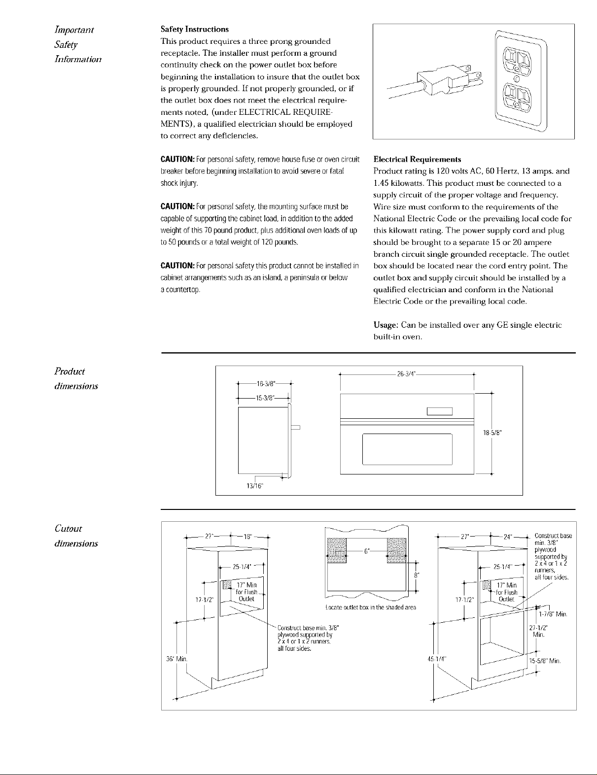
Product
dimensions
CAUTION: Forpersonal safety, removehouse fuse orovencircuit
breakerbefore beginninginstallation to avoid severeor fatal
shock injury.
CAUTION: for personalsafety, the mountingsurface must be
capable of supporting the cabinet load, in addition to the added
weight of this 70pound product, plus additional oven loadsof up
to 50 pounds or atotal weight of 120pounds.
CAUTION: Forpersonalsafety this product cannot be installed in
cabinet arrangementssuchas an island, a peninsulaor below
a countertop.
Electrical Requirements
Product rating is 120 volts AC, 60 Hertz, 13 amps. arid
1.45 kilowatts. This product must be connected to a
supply circuit of the proper voltage and frequency.
Wire size must conform to the requirements of tbe
National Electric Code or the prevailing local code for
this kilowatt rating. The power supply cord and plug
should be brought to a separate 15 or 20 ampere
branch circuit single grounded receptacle. The outlet
box should be located near the cord entry point. The
outlet box and supply circuit should be installed by a
qualified electrician and contbrm in the National
Electric Code or the prevailing local code.
Usage: Can be installed over any GE single electric
built-ln oven.
26-3/4"
L
18 5/8"
Cutout
dimensions
--211<_18"--
_J
J
13/16"
_Constructbase min3/8"
lywood supportedby
1×4o[1 × 2 runllers
aE[foursides
Locateoutletboxintheshadedarea
481/4"
_ .forHush
171/2"
Constructbase
rain3/8"
plywood
supportedb
2x4or1×_
fUnl_elS,
allfoursides
27-1/2"
Min
Page 3

Installation
Options
Monogram built-in ovens can be inset into the
cabinetry. In this installation the microwave is recessed
and flush with the front surface of the cabinet.
A shadow box affect can be achieved by installing a rail
at the top and bottom of the microwave to fill the
cutout height. In this installation, exposed inside
surfaces of the cabinet should be finished to match the
cabinet surface.
• In both a recessed and shadow box installation, the
floor of the cutout must be level and even with the
bottom edge of the cutout. Use runners inside the
opening to raise the floor to matching height.
Step 1
Slide the
microwave
into cutout
Inset/Recessed Installation
• Cut 4 stopper strips, 13/16" square to frame the
opening, install the strips 13/16" from the fi'ont edge
of the opening. Oven overlap will cover all 4 stopper
strips.
Toolsand Materials
required:
• #2, Phillips screwdriver
• Handhetd drill motor
• High speeddrill bit, 1/8"
diameter
• Lift unit into cabinet cut-out.
• While supporfing the unit, place on a 45° angle and
plug in the power cord. (Make certain the power
cord is not trapped under the bottom or on the
sides.)
• Slide the unit completely into the cabinet.
• 2each#8x1" Roundhead
wood screws
• 3/8", slothead screwdriver
Shadow Box Installation
• Cut top and bottom rail to fit the width of the
opening. Cut the height of the rails to fit the cutout
height. Use cleats to secure the rails to the inside
walls of the cabinets.
Before you begin Read these instructions completely
and carefully.
IMPORTANT Save these instructions for local
inspector's use.
IMPORTANT OBSERVE ALL GOVERNING CODES
AND ORDINANCES.
Note to Installer Be sure to leave these instructions
with the consumer.
Note to Consumer Keep these instructions with your
Use and Care Book for future reference.
Step 2
Relnove
grille
retainer
SCFPWS
• Open the door.
• Remove the iwo (2) retainer screws from the bottom
side of the grille (one at each side).
O
RetainerScrew/
Page 4

Step 3
Relnove
grille
Step 4
Drive
installation
S€I'eWS
• Roll the grille forward from the bottom
• Disengage the locating tabs, and remove the grille
from the unit.
CAUTION:Placetapeor
cardboardovertrimedgesfor
preventionof damagewhile
drillingpilotholes.
Installation
Screw
Hole
• Using the installalion holes as a guide, drill two (2)
pilot holes (I/8" diameter) into the cabinet.
• Install the two (2) installation screws.
Step S
Reinstall
• Reinstall the grille, by reversing the procedure used
in Step 2 & 3.
grille
O Monogram:
General Electric Compar_y
Louisville, KY40225
Note: While performing installations described in this book,
safetyglasses orgoggles should be worn.
To obtain specific information concerning any
Monogram product or semite, call GE Answer Cente/_
consumer information service at 800.6ZG2000 any
time, day or night.
_br Monogram local service in your area, call
1-800-444-1845.
NOTE: Product improvement is I continuing ende+wor _1 General [ile_ t tic
There[ore, m&terial_. _ppearm_ce and _ pe¢i[ications me _ubjec[ to change
wi[hout notice¸
Pub No 498798
© 1996 GE Appliances
(ND 400) 9/96
 Loading...