

Page 1

GE Monogram
Installation
Instructions
®
27" Built-In Ovens
Models
ZEK757WW
ZEK757BW
ZEK737WW
ZEK737BW
Page 2
CAUTION
WARNING
Before you begin—Read these instructions completely and carefully.
IMPORTANT: Save these instructions for local inspector’s use.
IMPORTANT: OBSERVE ALL GOVERNING CODES AND ORDINANCES.
NOTE TO INSTALLER: Be sure to leave these instructions with the
Consumer.
NOTE TO CONSUMER: Keep these instructions with your Use and Care
Book for future reference.
This appliance must be properly grounded. See “Electrical Supply”, page 16.
Contents
2
If you have questions concerning the installation of this product, call the GE Answer
®
Center
800.626.2000, 24 hours a day, 7 days a week.
If you received a damaged oven, you should
contact your dealer.
CAUTION:
• This oven should be installed by a qualified
• Never use the oven for warming or heating a
Consumer Information Service at
installer or service technician.
room. Prolonged use of the oven without
adequate ventilation can be hazardous.
Proper installation is the responsibility of the
installer. Product failure due to improper installation
is not covered under the GE Appliance Warranty. See
the Use & Care Guide for warranty information.
Check with local utilities for electrical codes which
apply in your area. Local codes vary. Installation,
electrical connections and grounding must comply
with applicable codes. In the absence of local codes,
the oven should be installed in accordance with
National Electrical Code ANSI/NFPA 70-1990.
Design Information
Models Available..................................................................................................................................3
Dimensions and Clearances ...............................................................................................................3
Cabinet Style Options .........................................................................................................................4
Installation Options ............................................................................................................................5
Side-by-side Installation Option .........................................................................................................5
Cabinetry
Tools and Materials required .............................................................................................................6
Framed Cabinet, Double Oven ..........................................................................................................6
Framed Cabinet, Single Oven ............................................................................................................7
Recessed Installation: Front framed cabinets with inset doors and drawers..................................8
Frameless Cabinets..............................................................................................................................9
Single Oven Installed Below a Microwave Oven.............................................................................10
Single Oven Installed Below a Countertop...................................................................................... 11
Cabinetry Modification Suggestions
Provide Oven Supports .....................................................................................................................12
Install Oven Supports........................................................................................................................12
Determine Need for Filler Panels.....................................................................................................13
Filler Panel Construction ..................................................................................................................13
Cut Rail for Filler Panel ....................................................................................................................14
Cut Appearance Panel ......................................................................................................................14
Determine Location of Cleats...........................................................................................................14
Cut and Secure Cleats to Filler Panel...............................................................................................15
Secure Rail to Appearance Panel .....................................................................................................15
Secure Assembled Filler Panel to Cabinet .......................................................................................15
Installation
Tools and Materials Required ..........................................................................................................16
Electrical Locations ...........................................................................................................................16
Finalize Installation ...........................................................................................................................17
Route Cable Through Cutout...........................................................................................................17
Secure Oven to Cabinet ....................................................................................................................18
Replace the Oven Door.....................................................................................................................18
Connect Electrical .............................................................................................................................18
Page 3
Design Information
Built-In Ovens
Models
available
ZEK757WW
White double convection oven
ZEK757BW
Black double convection oven
ZEK737WW
White single convection oven
ZEK737BW
Black single convection oven
With both single and double built-in styles, contemporary Monogram ovens of fer an array of choices for the
custom kitchen:
• Built-in double convection ovens
• Built-in single convection ovens
• Monogram built-in ovens are available in sophisticated black or glistening white.
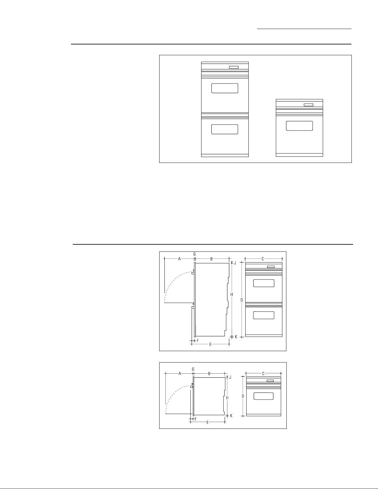
Dimensions
and clearances
Double oven
A - 20" (508 mm)
B - 23-1/2" (597 mm)
C - 26-13/16" (681 mm)
D - 50-3/4" (1289 mm)
E - 26-3/16" (665 mm)
F - 1-3/4" (44 mm)
G - 15/16" (24 mm)
H - 49-5/8" (1260 mm)
J - 1/4" (6 mm)
K - 7/8" (22 mm)
Single oven
A - 20" (508 mm)
B - 23-1/2" (597 mm)
C - 26-13/16" (681 mm)
D - 28-9/16" (725 mm)
E - 26-3/16" (665 mm)
F - 1-3/4" (44 mm)
G - 15/16" (24 mm)
H - 27-7/16" (697 mm)
J - 1/4" (6 mm)
K - 7/8" (22 mm)
3
Page 4
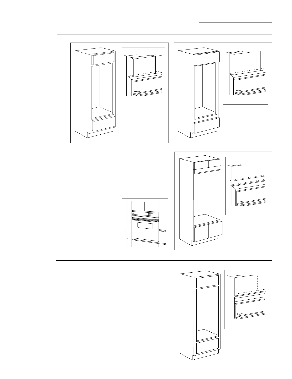
Cabinet style
options
Design Information
Built-In Ovens
Front Framed Partial Overlay Door
Monogram ovens are installed directly into a wall or
wall oven cabinetry, 27" minimum width. The front
surface of the ovens will be nearly flush with surrounding cabinetry. To obtain optimal appearance,
cabinet cutouts must be exact. The examples shown
here illustrate typical styles of 27" cabinets and oven
fit. Installation instructions for each of these basic
cabinetry styles are provided in this section.
Designer Note:
possible, align the oven with
cabinetry details such as
drawers, doors and reveals.
Whenever
Front Framed Full Overlay Door
Frameless
Monogram ovens can be recessed into front framed
cabinets with inset flush doors. This installation
requires 26-7/8" wide and 24-1/2" deep cutout. See
page 6 for details.
Recessed Installation In
Front Framed Inset Flush Door
Note:
This installation requires
26-7/8" wide, 24-1/2" deep
cutout.
4
Page 5
Design Information
Built-In Ovens
Installation
options
Single Oven Installed Below A
ZMC1090WV/ZMC1090BV Microwave Oven
• Install a single oven alone or below any Monogram
microwave oven.
• For an integrated look, install a single oven below
the ZMC1090BV and ZMC1090WV built-in style
microwave ovens. No trim kits required.
• Install a single oven below a ZEM200WV microwave
oven. JX827WN trim kit required.
Single Oven Installed Below A
ZEM200WV Microwave Oven
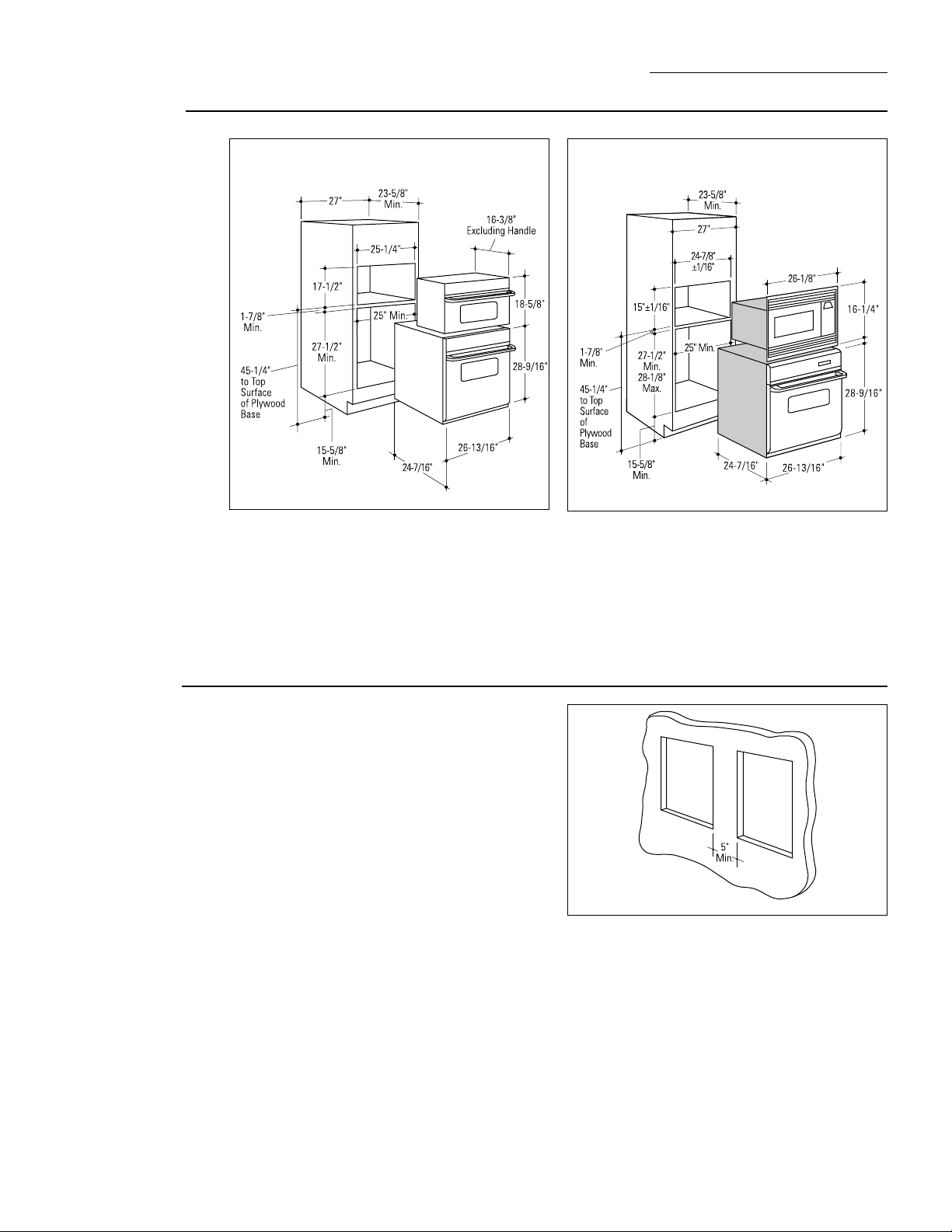
Side-by-side
installation
option
Install single ovens side-by-side. Minimum spacing
allowed:
• 5" minimum separation between cabinet openings—
any type oven.
5
Page 6
Cabinetry
Built-In Ovens
Tools and
materials
required
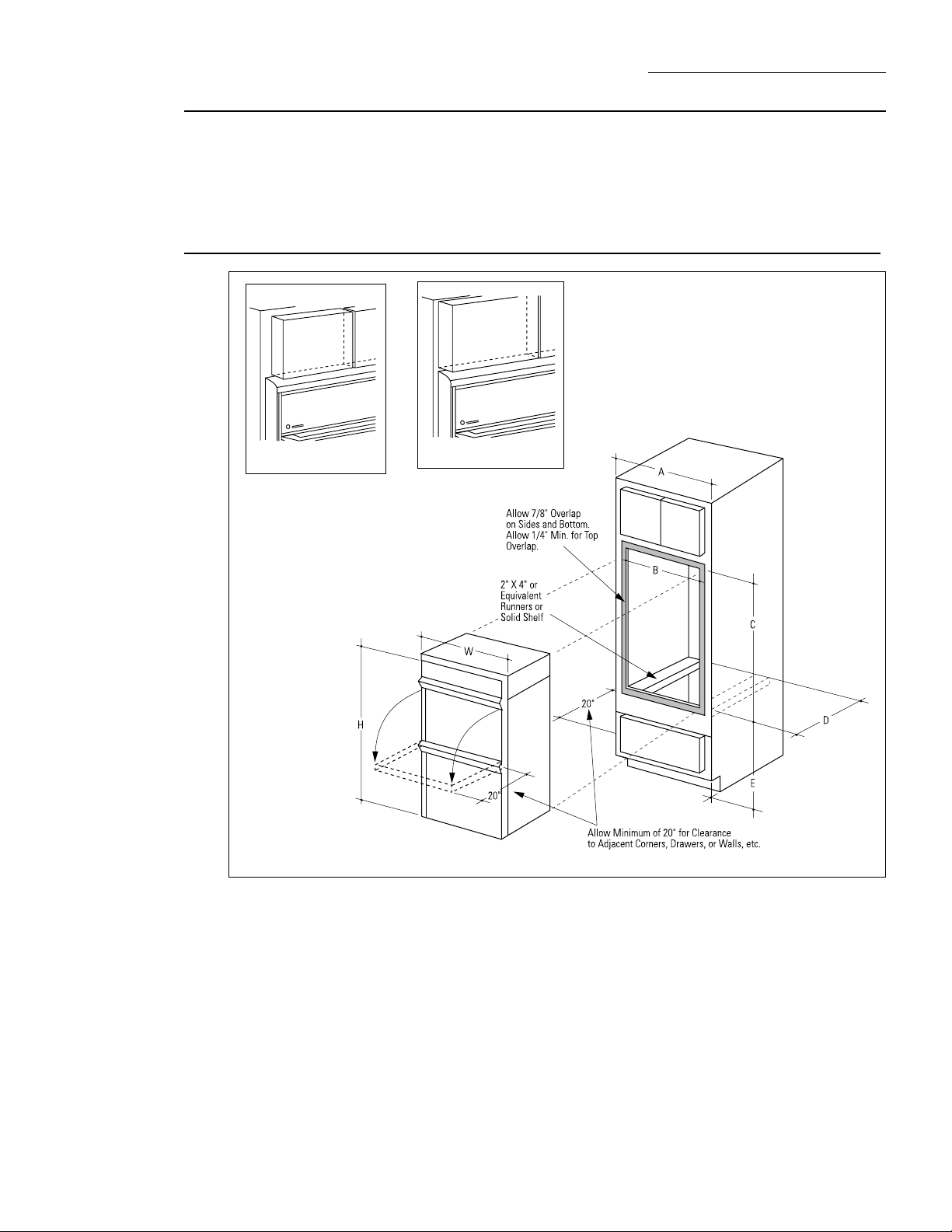
Framed cabinet
double oven
• 2" x 4" lumber for runners
• Saw
• Level
• Phillips screwdriver and wood screws or other hardware for
installing runners or shelf to support oven.
Front Framed
Partial Overlay Door
DIMENSIONS
A Cabinet Width 27" Min.
B Cutout Width 25 " Min.
C Cutout Height 49-11/16" Min./50-1/8" Max.
D Cutout Depth 23-5/8" Min.
E Cutout Location 13-1/4" Min.
H Overall Height 50-3/4"
W Overall Width 26-13/16"
Front Framed Full
Overlay Door
Ovens are designed for installation in a cabinet 27" min. wide.
• Cut 2" x 4" runners of appropriate length or solid shelf to
support oven.
• Attach runners or solid shelf in opening as shown.
• Runners must be level and rigidly mounted.
Use the information in this dimension drawing for
typical framed cabinets. The front face of the oven
will be flush with cabinetry doors or drawers.
• Installing 13-1/4" from floor will place base of upper
oven at countertop level.
–May be more than 13-1/4" from floor, depending
upon user preference.
Order a double oven cabinet.
Rough opening for double oven must be:
• Depth—23-5/8" min. from inside back to front of
cabinet frame.
• All Monogram ovens require 7/8" overlap to
both sides and bottom. Allow 1/4" min. for top
overlap.
• Oven overlaps will conceal all raw edges.
• Width—25" min.
• Height—49-11/16" min. 50-1/8" max.
6
Page 7

Framed cabinet
single oven
Cabinetry
Built-In Ovens
Front Framed
Partial Overlay Door
DIMENSIONS
A Cabinet Width 27" Min.
B Cutout Width 25" Min.
C Cutout Height 27-1/2" Min./28-1/8" Max.
D Cutout Depth 23-5/8" Min.
E Cutout Location 32-1/2" Recommended
H Overall Height 28-9/16"
W Overall Width 26-13/16"
Front Framed Full
Overlay Door
Use the information in this dimension drawing for
typical framed cabinets. The front face of the oven
will be flush with cabinetry doors or drawers.
Order a single oven cabinet.
Rough opening for single oven must be:
• Depth—23-5/8" min. from inside back to front of
cabinet frame.
• Width—25" min.
• Height—27-1/2" min. 28-1/8" max.
• 32-1/2" from floor is recommended to bring oven
floor to countertop height.
• All Monogram ovens require 7/8" overlap on both
sides and bottom. Allow 1/4" min. for top overlap.
• Oven overlaps will conceal all raw edges.
7
Page 8

Recessed
installation:
Front framed
cabinets
with
inset doors
and drawers
Cabinetry
Built-In Ovens
Front Framed
Inset Flush Door
If you are using front framed cabinets with inset
doors, these ovens can be installed flush with the
front. In this installation the oven is completely
recessed into the cabinet.
Rough opening for single and double ovens:
• Depth 24-1/2" min. from inside back to front of
cabinet frame.
–If the cabinet is not 24-1/2" deep, the back of the
cabinet should be cutout. The cutout should be
This is achieved by installing cleats, set back 15/16"
from the front frame. The cleats will hold the oven
mounting screws. The cabinet must be wide enough
to allow 26-7/8" opening. Whenever possible, order
minimized in order to maintain structural strength
and squareness of the cabinet.
• Height—for double oven 50-3/4".
• Height—for single oven 28-9/16"
the cabinets with the cutout sized to fit the oven.
Note:
Provide this information to the cabinet manufacturer
in advance.
Installation in a recessed
application is not approved for
vinyl covered cabinets.
8
Page 9

Frameless
cabinets
Cabinetry
Built-In Ovens
Frameless
Use the information in this dimension drawing for
typical frameless cabinets. The front face of the oven
will be flush with cabinetry doors or drawers.
Whenever possible, order 27" frameless cabinet with
the cutout sized to fit the oven. If you are using stock
cabinets, additional finished filler pieces may be
required to cover openings.
Rough opening for single and double ovens:
• Depth—23-5/8" min. from inside back to front of
cabinet or side panel, excluding doors or drawer
fronts.
–If the cabinet is not 23-5/8" deep, the back of the
cabinet should be cutout. The cutout should be
minimized in order to maintain structural strength
and squareness of the cabinet.
• Width—25" min.
– Frameless cabinet inside width may be up to
25-3/4". Add 1/2" cleats to the sides, flush with
the front edge of the side panels to accept
mounting screws.
• Height—for double oven 49-11/16" min.
• Height—for single oven 27-1/2" min.
Both single and double ovens require 7/8" overlap
around edges of opening on both sides and bottom.
Allow 1/4" for top overlap.
• Allow 1/8" clearance between top of oven and
cabinet door or panel and 1/8" between bottom of
oven and cabinet drawer.
• Installation of double oven requires a total height of
51" including clearances at top and bottom.
• Installation of single oven requires a total height
of 28-13/16" including clearances.
9
Page 10

Single oven
installed
below a
microwave
oven
Cabinetry
Built-In Ovens
Microwave Ovens A B C
ZMC1090WV, ZMC1090BV 17-1/2" 25-1/4" 19" min.
ZEM200WN 15" ± 1/16" 24-7/8" ± 1/16" 18" min.
Order a double oven cabinet.
See the chart above for cutout dimensions and
receptacle locations for each microwave oven.
• Allow 1-7/8" clearance between microwave oven and
single oven, for trim kit or oven overlap.
Models ZMC1090WV and ZMC1090BV do not require
trim kits. When installed the outside dimensions will
be 26-3/4"W, 18-5/8"H.
• Model ZEM200WV requires JX827WN accessory
trim kit. When installed the outside dimensions will
be 26-1/8"W, 16-1/4"H.
Install a level base of 3/8" thick plywood, supported by
2"x4" or 1"x2" equivalent runners on all four sides:
–Flush with lower edge of opening and entirely
covering floor of opening.
• Finished microwave oven floor must support
minimum weight of:
–120 pounds for ZMC1090BV/WV.
–100 pounds for ZEM200WV.
10
Page 11

Single oven
installed
below a
countertop
Cabinetry
Built-In Ovens
C
Monogram ovens can be installed below a countertop.
The rough opening of the base cabinet should be:
• Depth–23-5/8" min. from inside back to front of
cabinet frame.
• Width–25" min.
• Height–27-1/2" min. 28-1/8" max.
All Monogram single ovens require 7/8" on both sides
and bottom. Allow 1/4" min. for top overlap.
• Oven overlaps will conceal raw edges.
Locate the junction box:
• 17-1/2" from the centerline of the opening to the
left side.
• 14" below the countertop.
Monogram 36" Halogen and ribbon cooktop can be
installed over a single oven. Refer to cooktop
installation instructions for cutout.
• Locate the junction box 16" min. below the
countertop.
11
Page 12

Provide
oven supports
Cabinetry Modification Suggestions
Built-In Ovens
Install
oven supports
The ovens may be supported by either a solid bottom
or 2 x 4 runners.
• The support must be level and rigidly mounted,
flush with the bottom edge of the cutout.
• The entire weight of the oven is supported by 2 x 4
runners or the solid floor and must be capable of
supporting 200 lbs. for double ovens and 150 lbs.
for single ovens.
If a solid bottom is used, a 6" x 10" rectangle must be
cut out to allow enough cooling airflow during a selfcleaning operation.
–Cut the solid bottom out of 5/8" min. thick
sheeting to fit the inside dimensions of the
cabinet. Measure 10-1/2" from left side and 7"
from the back wall. Cut the ventilation hole 6"
wide and 10" deep.
12
• Measure and mark the location of the runners or
solid floor.
–13-1/4" from the floor to the top of support, for
double ovens.
–32-1/2" recommended from the floor to the top of
support, for single ovens.
• Cut two pieces of 3/8" to 5/8" thick sheeting, to fit
inside cabinet depth and available inside cabinet
height. If there is no interference below the cutout,
such as drawer runners, the sheeting can rest on the
floor. Secure the sheeting strips or pieces to the
cabinet walls with screws. Lay 2 x 4 or solid bottom
on top of the sheeting and drive screws through the
top and into the sheeting.
Page 13

Cabinetry Modifications Suggestions
Built-In Ovens
Determine
need for
filler panels
If the cabinets being used have an opening that is
taller than the maximum dimensions indicated for
the ovens, filler panels can be made to fill the gaps.
Stock filler strips are usually available or for larger
gaps order an extra drawer front. Drawer fronts are
recommended because they will match the cabinetry
and have finished edges. Any cut edges will be seen
and should be finished.
Frameless cabinets usually come with a front panel
covering the opening. For the optimum finished look,
this panel can be removed and used to construct filler
panels.
The oven support floor and supports should be
installed at the required locations.
If there is a gap between the oven support floor and
the bottom of the opening, a bottom filler panel
should be constructed to fill the gap.
Measure from the oven support floor to the top of the
opening. If the opening height is larger than the
maximum cutout height, a filler panel should be
constructed to fill the gap.
Filler panel
construction
We suggest that the filler panel be constructed using
4 pieces:
• Appearance panel to match doors and drawers.
• A rail which will be covered by the oven overlaps
and conceal any slight gap between the top or
bottom of the oven and the start of the filler panel.
The face of the rail should be made of finished
matching material; the cut edges and ends do not
need to be finished.
• Cleats which will be used to secure the filler panel
and rail to the cabinet. One for each side.
13
Page 14

Cabinetry Modification Suggestions
Built-In Ovens
Cut rail
for filler
panel
Cut appearance
panel
Cut the rail out of finished material:
• The width should match cabinet opening width.
• The height of the top rail should be enough to
securely attach the rail to the appearance panel,
plus 1/4" oven trim overlap.
• The height of the bottom rail should be enough to
securely attach the rail to the appearance panel,
plus 7/8" oven trim overlap.
• The height of both the top and bottom rails should
be adjusted depending upon the height of the gap
to be filled or to enhance appearance.
Use drawer fronts for appearance panels or cut
finished material and finish raw edges.
• The appearance panel width should match drawer
fronts or doors.
• Make the appearance panel appropriate height to
fill the gap above or below the oven, allowing for
reveals and overlaps to match existing drawers or
doors.
Determine
location
of cleats
• To find the exact position of the cleats, place the
appearance panel onto the cabinet in desired
position and align to match the other drawers and
doors.
• Use a pencil to mark the back side of the panel
where it meets the cabinet corners.
14
Page 15

Cut and
secure cleats
to filler panel
Cabinetry Modifications Suggestions
Built-In Ovens
Secure rail
to appearance
panel
For the top filler panel:
• Cut 2 cleats out of 3/4" thick material, approximately 1-1/4" wide.
• Cut the cleats to a length leaving approximately
1/2" at the bottom of the appearance panel to
attach the rail.
• Position the outside edge and top of the cleat
against the corner pencil marks.
• Secure the cleat to the appearance panel with
screws.
Note:
The screws should be long enough to secure the cleats to the
filler panel without penetrating the appearance side.
• Place rail against cleats and flush with the outside
edges of the cleats. Secure with wood screws. If the
appearance panel is very narrow, cleats can be
attached to the rail.
For the bottom filler panel:
• Cut 2 cleats out of 3/4" thick material, approximately 1-1/4" wide.
• Cut the cleats to a length leaving approximately
1/2" at the top of the filler panel to attach the rail.
• Position the outside edge and bottom of the cleat
against the corner pencil marks.
• Secure the cleat to the appearance panel with
screws.
Note:
If appearance panel is very narrow, cleats can be attached to
the rail.
Note:
The screws should be long enough to secure rail to the filler
panel without penetrating the finished face of the filler panel.
Secure
assembled
filler panel
to cabinet
• Place filler panel in proper position. To attain
proper relationship to adjacent drawers and doors
you may need to space the filler panel out from the
cabinet face/edges using drawer bumpers or other
spacers.
15
Page 16

Installation
Built-In Ovens
Tools and
materials
required
Electrical
locations
• Outlet box
• Electrical cable—3-conductor or 4-conductor wire—as required
by local codes
• Flexible power cable connector
• Electrician’s pliers
Note:
Do not use an extension
cord with these appliances.
Monogram built-in single and double ovens require
a separate, properly grounded 3-wire 120/208 or 120/
240 volt, 60 Hz power supply, protected by a time
delay fuse or circuit breaker. Ovens are supplied with a
flexible power cable, which must be attached to a
junction box. The cable length is 48" for both single
and double conventional ovens. The cable length for
convection type ovens is 54".
Double ovens are rated 6.8 KW at 240 volt, and 5.1 KW
at 208 volt.
Single ovens are rated 3.4 KW at 240 volt, and 2.6 KW
at 208 volt.
16
The back of the ovens have chamfered corners which
provide a “chase” for the conduit when installing a
junction box above or below the oven(s).
The conduit is located on the back of the oven,
approximately 10" from the right side.
For double oven:
• Locate and install the junction box within reach of
the power cord.
– Approximately 10" from the left side of opening
– 56" minimum above the cutout floor
– or, through the left side of cabinet wall into
adjacent cabinet.
For single oven:
• Locate and install the junction box within reach of
the power cord.
– Approximately 10" from left side of opening.
– At least 5" below the cutout floor
– Or 34" minimum above the cutout floor
– or, through the left side of cabinet wall into
adjacent cabinet.
Double Oven:
Locate Junction Box
in one of the locations
Single Oven:
Locate Junction Box
in one of the locations
Page 17

Installation
Built-In Ovens
Finalize
installation
Install lower
oven trim
Caution:
oven door by handle. Door glass
breakage or handle damage may
occur. Glass surface of door face
extends beyond door frame on
each side; be careful not to
impact this exposed glass.
Caution:
removed and hinge arms are at
stop position, do not bump or try
to move hinge arms. Hinges
could snap back, causing an
injury to hands or damage to
porcelain surface.
Do not lift oven or
When door is
Remove oven door:
• Open the door to stop position.
• Grasp each side of door, lifting up and off the hinges.
• Cover hinges with toweling while working in oven
area.
• Secure lower front trim to the front frame with 3
Phillips head screws provided.
• Secure trim to the side trim with 2 #20 torx head
screws as illustrated.
Note:
The lower front trim is packed separately and should not be
attached until the oven is installed and secured to the installation
opening.
Route
cable
through
cutout
CAUTION
CAUTION
The bottom trim provides an opening for
cooling air to enter the cabinet. This
opening should never be blocked.
Note:
It is best that 2 people
perform this step: one to hold
oven in position and one to feed
cable.
With oven in front of cabinet opening:
• Start feeding the flexible power cable through
cutout.
• Insert oven 3/4 way into cabinet opening. Continue
to feed flexible power cable while sliding oven into
place. This is to insure that the flexible power cable
will not get trapped between the back of the oven
and the back of the cabinet wall.
CAUTION
CAUTION
Be sure you do not tip the unit forward
during installation or you may bend the
Lower Side Trim.
17
Page 18

Installation
Built-In Ovens
Secure
oven
to cabinet
Replace the
oven door
• Slide oven into cabinet opening.
• Drill 3/32" pilot holes through mounting holes in
oven front frame. (2 screw holes for single ovens,
4 screw holes for double ovens.)
• Secure oven in place with screws furnished. (Use
drywall screws if cabinet is particulate board).
WARNING
CAUTION
Securely fasten oven to cabinet using the
screws provided. Failure to do so could
cause the oven to move or tip during use
and result in personal injury.
• Remove toweling. The hinges should still be in stop
position.
• Slide the door down onto the hinges as far as it will
go. Close the door.
Connect
electrical
With oven installed:
• Connect oven power cable to junction box, using
flexible power cable connector.
–Be sure connections are secure.
18
Page 19

Installation
Built-In Ovens
Connect
electrical
(continued)
• When connecting to a 3-conductor branch circuit:
–Connect oven red lead to branch circuit red lead.
–Connect oven black lead to branch circuit black
lead.
–Connect oven bare copper conductor and white
lead to branch circuit neutral lead (white or gray).
• When connecting to a 4-conductor branch circuit:
–Connect oven red lead to branch circuit red lead.
–Connect oven black lead to branch circuit black
lead.
–Break connection between oven white lead and
oven bare copper conductor.
–Connect oven white lead to branch circuit neutral
lead (white or gray).
–Connect oven bare copper conductor to branch
circuit ground lead (green or bare copper).
Note:
Aluminum house wiring
requires use of special
aluminum-to-copper connectors.
Follow manufacturer’s
instructions carefully.
19
Page 20

Monogram.
General Electric Company
Louisville, KY 40225
NOTE: While performing installations described in this book,
safety glasses or goggles should be worn.
To obtain specific information concerning any
Monogram product or service, call GE Answer Center
®
consumer information service at 800.626.2000—any
time, day or night.
For Monogram local service in your area, call
1-800-444-1845.
NOTE: Product improvement is a continuing endeavor at General
®
Electric. Therefore, materials, appearance and specifications are
subject to change without notice.
Pub. No. 49-8804
1996 GE Appliances
(N.D. 616) 9/96
 Loading...