

Page 1

Installation
Instructions
SidebySide Refrigeraters
Design Guide
With Instannation instructions
Monogram:
Page 2
Safety information
BEFORE YOU BEGBN
Read these instructions completely and carefully.
•IMPORTANT- Sa.e hese
for local h_spector's use. Observe a]] governim_g codes
amid ordi m_am_ces.
• Note to Installer - Be sure to ]cave these
im_structions with the (}om_sm_er.
• Note to Consanler -Keep d]ese im_sm,cdo_s
with ,our Om_er's Mamta] for futm'e referem)ce.
WARNING:
This app]hmce ml*s[ be properly grom]ded. See
"C,rom)dh)g [he P,etHgeramr," page ]H.
AVERT SSEMENT
Cet appare]] doit 0tre correcteme])t m]s {t_]a terre.
Consl*]ter << M]se fi ]a terre (h_ r(_iHg(_ratem" ,>,page ] 0.
lf"_ou received '_ darn'wed refrigerator, "_ou should
immediateh _ontact _om" dealer or builder.
Dl*e to the weight am)dsize of this re{Hgerator, am]
to recline the risk of persom:d iqim T or damage to
the product - THREE PEOPI,E ARE RE@ lINED
FOR PROPER INSTAI,I,ATK)N OF A 36" WlDE
UNIT. FOUR PEOPI,E ARE REQUIRED FOR
INSTAI,I,ATION OF A 42" OR 48" WIDE MODEl.
PRUDENCE
cause du poids et de ]a tai]]e de ce r_frige_rator et
pour r_4duire ]e risque de b]essm'e et de dommages,
li, FAIJT TROIS PERSONNES PO[JR INSTM,I,ER
COI_,RECTEMENT D'IJN &PP&REII, DE 91 cm (36 po)
DE LAk(,E. Ii, FAiJT Q[ J_TRE PERSONNES PO[JR
I ilNSTM,I,ATION D' [JN MODI_I,E DE 1H7 O[ / 122 cm
) ,
(42 OI / 48 po) DE lARGE.
Skill Level - h_sta]]athm of this refrigerator
requires basic mecham_ica], carpem_tr? amid phm_bim_g
skills. Proper i m>ta]h_ti(m is the reslxmsibi]it} of the
im/sta]]er. Product {hi]m'e <]tie to improper im/sta]]atiom/
is Nmt covered m_der the (;E _pp]iam_ce _,_arr;mtv.
See t]_ e ()w]_ e]"s N_a _ I 0a] for WaFFa _1t_ ] _1['OFI)) a t] o11.
WARNING:
* These refrige_:m)rs are top-hea_) am] m_st
be secm'ed to preve_t the possibility of tippi_g
flu'ward. A_ti-Tip protection is req_dred. See
[)age ] 2 for detai]s.
* IJse this app]ia_ce only fin" its ]_temIed purpose.
* Immediately repair or replace electric service cords
that become f}'ayed or damaged.
* I I_q)]ug the reiHgerator before c]ea_h_g or maki_g
* Repairs should be made b} a qualified service
tech _ icia _.
AVERTISSEMENT
*Ces r_}Hg&'a[eurs sm)[ ]om'ds e_) ham e[ il }im[ ]es
_vi [er ]e_r bascu] em e]_L I] fh m avoir
m) svstbme de protection) co_m'e ]e re])vergeme])t.
Voh" ]es d_tai]s page 12.
* II _]e [h_g uti]iser cet apparei] q_e po_r ]'_ti]isati(m
* Re, parer o_* remp]acer ]mm&]iateme_t tol*t cordo]l
_lectriq_*e eiti]och(_ o_* emIommag(_.
* l] %at dSbra_cher ]e r65igSrateur awmt ]e
aettoyage ou rouge h_te]we]]t](m.
* i,es reSparations doivent _tre f_dtes par m_
tec]micie]_ q _*a]ifi(_.
For Monogram local service in your area, call
1.800.444.1845.
For Monogram service in Canada, call
1.888.880.3030
For Monogram Parts and Accessories, car
1.800.626o2002.
www. mmmgram.com
Plam_i_g 6uide
The Installation Space ....................................3
Dimensions and Clearances ..........................3
130° Door Swing ..............................................4
%° Door Swing ................................................5
Customization Basics ......................................6
1/4"Framed Panel Dimensions ......................7
3/4"Overlay Panel Dimensions......................8
Raised Overlay Panel Design ........................9
Side Panels......................................................10
Installation Instmctieas
Tools, Hardware, Materials ........................ 10
Grounding the Refrigerator .......................... 10
Step 1, Remove Packaging .......................... 11
Step 2, Install Water Line ............................ 11
Step 2A, RO Water Line ................................ 12
Step 3, Install Side Panels ..........................12
Step 4, Install Anti-_p Brackets ................ 12
Step 5, Level Refrigerator ............................ 13
Step 6, Alternate Anti-_p Procedure ........ 13
Step 7, Secure Refrigerator to Cabinetry _14
Step 8, Adiust Door Swing .......................... 14
Step 9, Install Grille Panel ............................ 14
Step 10, install Framed Panels .................... 15
Step IOA, install Overlay Panels .......... 16-17
Step 11, install Dispenser Trim .................... 18
Step 12, Connect Water Supply .................. 18
Step 13, Cormect Power .............................. 19
Step 14, Start Icemaker ................................ 19
Step 15, install Toekick ................................ 19
Page 3
Design Guide
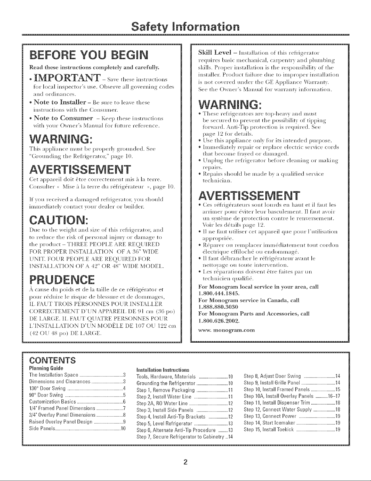
THE INSTALLATION SPACE
36"Models12"
42"Models18"
48"Models20"
75"FromFloor
to Bottom
ff Electrical
Area
*The finished cutout width must be:
35-1/2" fin" 36" models
41-1/2" for 42" models
47-1/2" fin" 48" models
Water And Electrical Locations
The opening must be prepared with the electrical
and water supi)ly located as shown.
The cutout depth must be 24"
The refrigerator will project fin'ward, slightly beyond
ac!jacent cabinetry, depending on yore" installation.
Cutout depth beneath a soffit:
When installed beneath a soffit, the soffit cannot
exceed the 24" installation depth shown. The top case
trim overlaps the bottom of the soffit.
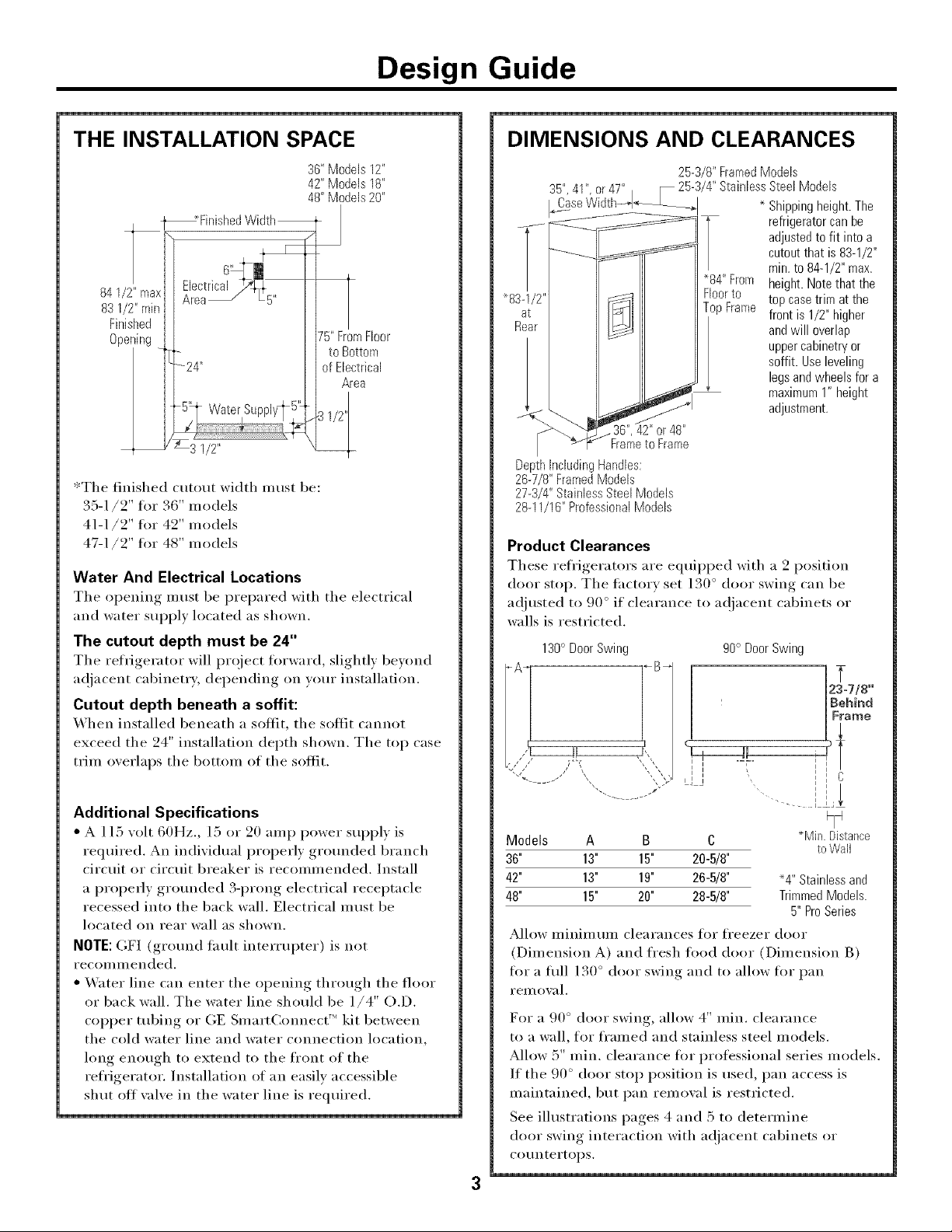
DIMENSIONS AND CLEARANCES
25-3/8"FramedModels
35",41",or47" _ 25-3/4"StainlessSteel Models
]._aCaseWidth_..] * Shippingheight.The
•84"From height.Notethatthe
832
Rea
36",42"or48"
Frameto Frame
DepthincludingHandles:
26-7/8"FramedModels
27-3/4"StainlessSteelModels
28-11/16"ProfessionalModels
Product Clearances
These refrigerators are equii_ped with a 2 position
door stop. The tactorv set 130 ° door swing can be
a(!justed to 90 ° if clearance to a(!jacent cabinets or
walls is restricted.
130° DoorSwing
,J
Floorto top casetrim at the
TopFrame front is 1/2"higher
refrigeratorcanbe
adjustedto fit intoa
cutoutthat is 83-1/2"
min.to 84-1/2"max.
andwill overlap
uppercabinetryor
soffit. Useleveling
legsandwheelsfor a
maximum1"height
adjustment.
90° DoorSwing
23=7/8"
Behind
Frame
l
C
Additional Specifications
• A 115 _olt 60Hz., 15 or 20 amp power suppl_ is
required. An indixidual properl) grotmded branch
circuit or circuit breaker is recommended. Install
a I_r° I_erlv, ,gr°tmded 3-i_ron _, electrical receptacle
recessed into the back wall. Electrical must be
located on rear wall as shown.
NOTE: GF] (grotmd tault interrupter) is not
recoi/llllended.
• Water line can enter the oi_ening, through, the floor
or back wall. The water line should be 1/4" O.D.
copper tubing or (;E _martC_ nnect kit between
the cold water line and water connection location,
long enough to extend to the front of the
refrigerator. Installation of an easily accessible
shut off xalxe in the water line is required.
S _ ) ii
Models A B C *Min. Distance
36" 13" 15" 20-5/8"
42" 13" 19" 26-5/8" '4" Stainlessand
48" 15" 20" 28-5/8" TrimmedModels.
Allow minimmn clearances for fl'eezer door
(Dimension A) and fresh ti)od door (Dimension B)
tot a flfll 130 ° door swing and to allow tot pan
I'eII/ox_ll.
For a 90 ° door swing, allow 4" rain. clearance
to a wall, for framed and stainless steel models.
Allow 5" rain. clearance for professional series models.
If the 90 ° door stop position is used, pan access is
maintained, but pan remoxal is restricted.
See illustrations pages 4 and 5 to determine
door swing interaction with ac!jacent cabinets or
cot/ntertol) S.
toWall
5" ProSeries
Page 4
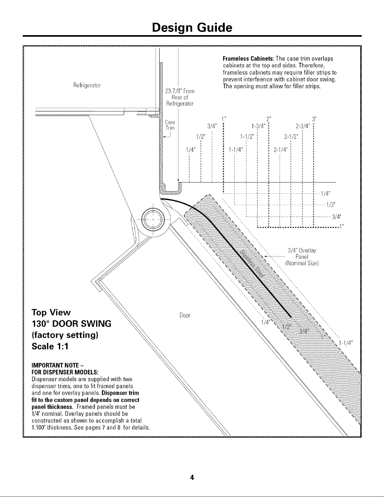
Refrigerator
Design Guide
FramelessCabinets:The case trim overlaps
cabinets atthe top and sides. Therefore,
frameless cabinets may require filler strips to
prevent interfeence with cabinet door swing.
Theopening must allow for filler strips.
23-7/8"From
Rearof
Refrigerator
Csse
Trim
3/4"
1/2"
1/4"
3/4"Overlay
Panel
"', (NominalSize)
Top View
130 ° DOOR SWING
(factory setting)
Scale 1:1
IMPORTANTNOTE-
FORDISPENSERMODELS:
Dispenser models are supplied with two
dispenser trims, oneto fit framed panels
and one for overlay panels.Dispenser trim
fitto thecustompanel dependsoncorrect
panelthickness. Framedpanels must be
1/4"nominal. Overlay panelsshould be
constructed as shown to accomplish atotal
1.100"thickness. See pages 7 and 8 for details.
Door
4
Page 5
Design Guide
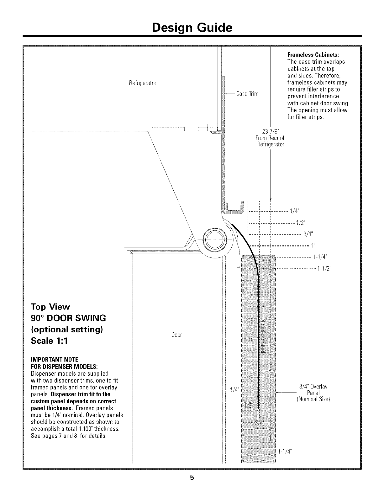
Refrigerator
CaseTrim
FramelessCabinets:
The case trim overlaps
cabinets at the top
and sides.Therefore,
frameless cabinets may
require filler strips to
prevent interference
with cabinet door swing.
The opening must allow
for filler strips.
23-7/8"
FromRearof
Refricerator
k
i i
i i
' ' ' 1/4"
Top View
90 ° DOOR SWING
(optional setting)
Scale 1:1
IMPORTANTNOTE-
FORDISPENSERMODELS:
Dispensermodelsare supplied
with two dispenser trims, oneto fit
framed panels and onefor overlay
panels. Dispensertrimfit tothe
custompaneldependsoncorrect
panelthickness. Framedpanels
must be 1/4"nominal. Overlaypanels
should be constructed as shown to
accomplish atotal 1.100"thickness.
See pages 7 and 8 for details.
1-1/2"
Door
3/4" Overlay
Panel
(NominalSize)
Page 6
Design Guide
CUSTOMIZATION BASICS:
Framed Or Overlay Panels, Custom Handles and Accessory Kits
Professional Style Stainless Steel Refrigerators
Stainless steel wrapped reti'igerators ha;'e beveled edges
and professional style handles. These models are
shii_ped ready fl)r installation.
Stainless Steel Wrapped Refrigerators
Stainless Steel wrapped refiigerators ha;'e wrapped
doors and grille panel, beveled edges, and tubular
stainless steel handles that coordinate with other
Monogram appliances. These models are shii)ped
ready for installation.
Trimmed Refrigerators
Trimmed refrigerators are designed to be customized
with decorative panels. Field installed custom door
and grille panels are required.
Framed panels
You may install 1/4" thick custom panels ti'om yore"
cabinet manufhctm'er. The decorative panel slides into
the tactorv installed trim. Or, order black, white and
stainless steel accesso_ T panels fl'om yore" Monogram
dealer.
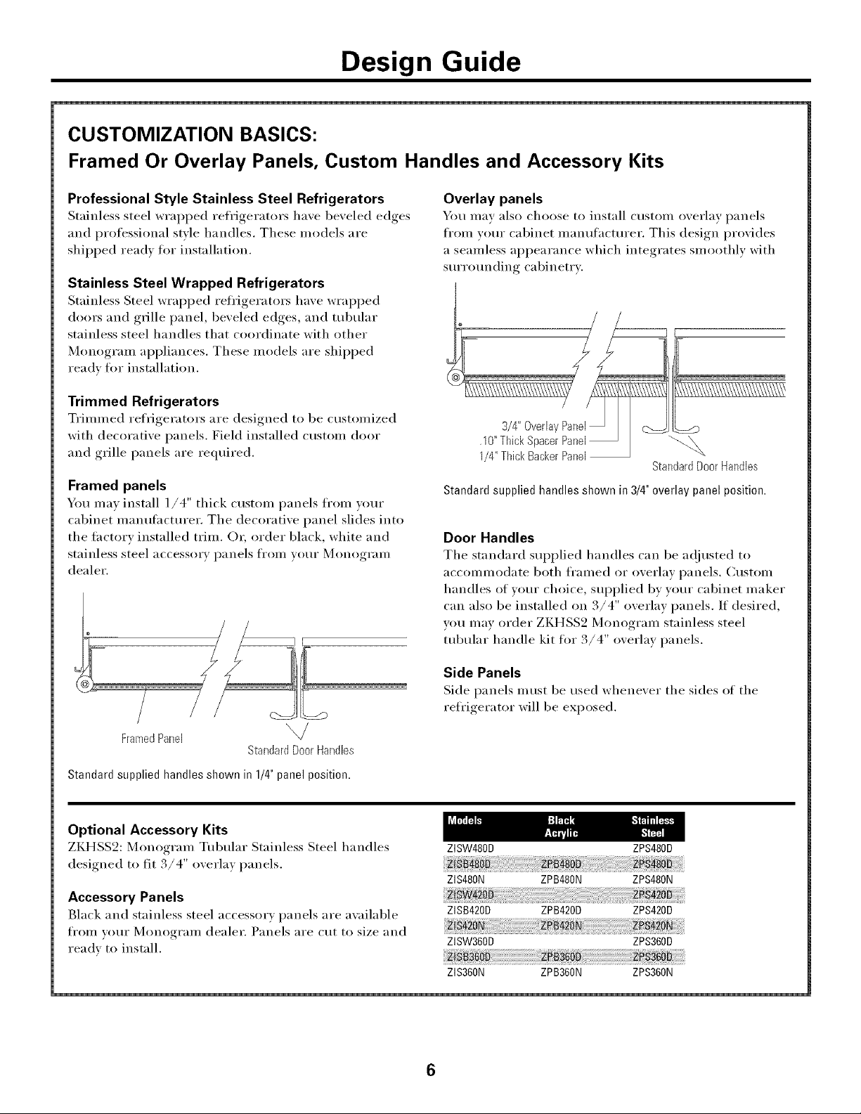
Overlay panels
You may also choose to install custom overlay panels
fl'om wmr cabinet mantflhcturer. This design provides
a seamless appearance which integrates smoothly with
stu'rotmding cabinetry.
StandardDoorHandles
Standard supplied handles shown in 3/4"overlay panel position.
Door Handles
The standard supplied handles can be a(!iusted to
accommodate both fl'amed or overlay panels. Custom
handles of your choice, SUl_plied by your cabinet maker
can also be installed on 3/4" overlay panels. If desired,
you may order ZKHSS2 Monogram stainless steel
tubular handle kit fl)r 3/4" overlay panels.
/
FramedPanel
StandardDoorHandles
Standard supplied handles shown in 1/4" panel position.
Optional Accessory Kits
ZKHSS2: Monogram Tubular Stainless Steel handles
designed to fit. /4 oxerla) panels.
Accessory Panels
Black and stainless steel accessory panels are awfilable
from vom" Monogram dealer. Panels are cut to size and
ready to install.
Side Panels
Side panels must be used whene_er the sides oI the
refrigerator will be exposed.
ZISW480D ZPS480D
ZIS480N ZPB480N ZPS480N
ZISB420D ZPB420D ZPS420D
ZISW360D ZPS360D
ZIS360N ZPB360N ZPS360N
6
Page 7

Design Guide
1/4" FRAMED PANEL DiMENSiONS
lf_ou choose to ira)stall framed ixme]s, they midst be
clot to the sbowm The pam_e]s _rd]] slide
im_to the frame o]_ the door amid grille.
Door
777__ Trim
Reveal
Non=Dispenser Models
If the cl_stom p;me] is less tbam_ 1/4" thick amid it fits
loosely im_tile door fl'ame it cam_ be backed I_[_ with
a piece of filler material or fl)am tape to improve
the fit.
IMPORTANT NOTE - DISPENSER MODELS
The refiigerator is sui)plied with two dispenser trims,
one for fl'amed panels and one for overlay panels.
• If the panel is less than 0.250" thick a noticeable
gap may be created aroui]d the dispenser trim.
Foam tape may be applied on the door to improve
the fit.
DispenserCutout
Grille Panel E
\
i
i
t
IMPORTANT NOTE: Maximum total panel weight:
• Fresh food door panel-75 Ibs.
• Freezer door panel -53 Ibs.
• Grille Panel - 18 Ibs.
• If the panel is more than 0.950" thick, the
dispenser trim cannot be secured to the door.
See Dispenser Trim Fit Example, page 9.
Theframed panel must be 1/4"nominal thickness
to fit the dispenser trim.
I/4"
Panel
7
Dispenser
Cutout
Freezer FreshFood
Panel Panel
F
D E
15-3/8"
I_ 9-5/S"
C
Side-by-Side(ininches)
36"Models 33-7/8 9 68-3/8 14-9/16 18-9/16
42"Models 39-7/8 9-1/2 68-3/8 14-9/16 24-9/16
48"Models 45-7/8 9-1/2 68-3/8 18-9/16 26-9/16
Page 8

Design Guide
3/4" OVERLAY PANEL DiMENSiONS
For a more c_stom aI)pearam_ce, overlay i)m]els may be
im_sta]]ed on trimmed mode]s_ The overlay pam_e] midst
be secm'ed to a 1/4'* thick bac] er pam_e] _h]c]] slides
im_to the tri m. A spa cer pan e] 0. ] 0" thick m I_st be
p]ace(] betweeN_ the overlay am_d backer pm_ el.
Assemble the pm_e]s wit]] gh_e m_d screws.
* Center the spacer pam_e] om] the backer pam_e], left to
right amid top to bottom. Secm'e the pm_e]s _dth gh_e.
* C,eN_ter the spacer amid backer [xme] o]] the overlay
pa N_e] am_d secl*re with glue a N_d screws. Screws m i_st
be com_tersm_k im_to the backer paN, el.
IMPORTANT NOTE- DISPENSER MODELS
The refiigerator is sui)plied with two dispenser trims,
one for ti'amed panels and one ti)r oveday panels.
The overlay dispenser trim is designed to fit a total
panel thickness of 1,100",
• If the panel is less than 1.100" a noticeable gap may
be created arotmd the dispenser trim.
• If the panel is more than 1,100" the dispenser trim
cannot be secured to the (loot'.
See Dispenser Trim Fit Example, page 9.
_E
Door
I/4"
Backer 1O"
Panel _Bpacer
NOTE: Left-to-right offset
is not always equal to
top-to-bottom offset,
.250" + .10" + .750" = 1.100"TotalPanelThickness
• The overlay panel must be constructed according to
the specifications shown to achieve the correct total
thickness.
• Alternative panel construction methods such as
secming a 3/4" panel to a 1/4" backer panel cannot
be used. Another method, routing a 3/4" thick
panel on all sides cannot be used. These methods
will not result in the required 1,100" panel thickness,
When a raised panel design is to be used, a custom
middle rail is required, Nee page 9 for details,
OverlayPanel
' BackerPanel
Grille Panel ]E
Dispenser
Cutout
Freezer Fresh Food
Panel Panel
F
I--D _E_
DispenserCutout
*Cut the dispenser opening after the backer, spacer and overlay
panels have been assembled.
IMPORTANT NOTE:Maximum total weight for the assembled
15-3/8"
panels:
• Fresh food door panel-75 Ibs.
• Freezer door panel -53 Ibs.
• Grille Panel- 18Ibs.
1_ 9-5/8" _1
36" Side-by-Side (in inches)
C
1/4"BackerPanel 33-7/8 9 68-3/8
.10"SpacerPanel 33 8-3/8 67
3/4"OverlayPanel 34-1/8 9-1/4 68-5/8
14-9/16 18-9/16
13-1/4 17-1/4
14-13/16 18-13/16
42"Side-by-Side(ininches)
1/4"BackerPanel 39-7/8 9-1/2 68-3/8 14-9/16 24-9/16
.10"SpacerPanel 39 8-5/8 67 13-1/4 23-1/4
3/4"OverlayPanel 40-1/8 9-3/4 68-5/8 14-13/16 24-13/16
48"Side-by-Side(ininches)
1/4"BackerPanel 45-7/8 9-1/2 68-3/8 18-9/16 26-9/16
.10"SpacerPanel 45 8-5/8 67 17-1/4 25-1/4
3/4"OverlayPanel 46-1/8 9-3/4 68-5/8 18-13/16 26-13/16
8
Page 9

Design Guide
DISPENSER MODELS:
RAISED OVERLAY PANEL DESIGN
Whem_ _ _'_dsed p_mel design is to be i_sed, _
cl_stom w](]e middle _'a]l is _'eql_]_'e(] to accept
the (]ispem_se_ _ t_'im.
• The middle x'_il midst be wide em)l_gh to _dlow
fk_ _ the dispe]_se_ _tx'im to ove]'lup the ope]_in_,
• The middle x'_il midst be ].]O0" total thick]_ess
to :]ccept the dispe]_se_ _tx'im.
1/4" Backer
.10"S_
3/4"OverlayPanel
3ispenser
Trim
16-3/4"
DISPENSER TRiM FiT EXAMPLES:
{NOT TO SCALE}
1/4" FRAMED PANEL
• The (]]spe_se_" t_'im fits ove_" the
c_stom paN, el _mc[ s_aps i_to the
f}'eeze_" dooi'.
The clips will ,_ot e_a_e the doox" if
the i)a_e] is mox'e them 0.250" thick.
If the pa_e] is less tha_ 0.250" thick,
a m)t]ceab]e gap m_v be c_'eated
:_x'om_(] the (]ispei_sex" tI'im.
3/4" OVERLAY PANEL
The (Iispe_se_" t_'im fits ove_" the
c_stom pa_e] _mc[ s_aps i_to the
f}'eeze_" (1ooi'.
The clips will _ot e_ga_e the doo_" if
the pa_eI is mo_'e t]]_m ].]00" thick.
If the pa_e] is less t]]a_ ].]00" thick,
:_ _oticeab]e gap may be cx'eatec[
_'om_(] the (]is[)ei_se_" ti'im.
10-5/8"--___
FREEZERDOOR
1/4" 0.250"
Frareed Thick
1/4" Dispenser Trim
1/4"Sacker Pane! FREEZERDOOR
1.100"
.10"Spacer T0tal Thickness
Panel
314"Overlay Dispenser Trim
Page 10

Design Guide
SIDE PANELS
Side pa,_els must be used
whenever the sides of the
refrigerator will be
exposed. The 1/4" side
pam_els will sli p im]to the
side case trim. Secm'e the
pm_e]s to the refrigerator
with stick-o_ hook a_]d
loop fhstener st_:ips. Order
the side pm_e]s from the
cabhlet mare?H[_ctllrer.
* (Mt a m_otch h_ the top
from_t cor]_er as show]]
to allow clearam_ce {or
comer ke_s ira?the fro]?t
side trim.
_84"
Depending on installation height.
TOOLS REQUIRED
• Tim_s_ips to cm bam_dim_g
• Stepladder
• Blinker
• l,eve]
• App]iaN_ce H;md Track
• T_b]m_g cl_tter
• 7/] 6" o[:)em_-em_d w reN_ch
• #2 Phi]lips screwdriver
• Drill a_(] appropriate bits
• :7/16", 7/16" socket
• Sa{ety glasses
• 1-1/4" opem_ em_dwreN_ch
• Pliers
• 1/4" ratchet wrench
• #2 Stubby Phi]lips screwdriver
HARDWARE SUPPLIED
• Water filter bypass piing
• A_ti-Tip brackets
• ]/4" m_t amp(I!ferrule
• D]sp en se r t ri m s for ] / 4" a _ d 3/ 4" over] ay pa _ e]s
• Ahm_im*m cover trim fl)r 3/4" overlay pa_*e]s with
c_stom handles, h_ch*des 22 fiat head screws a_(]
FLOORING
For proper installation, this refrigerator must be
placed on a lexel sm'tace of hard material that is
at the same height as the rest of the flooring. This
surface shouhl be ,strono_ enough, to support a fifth'
loaded refrigerator, or approximatel) 1,500 lbs.
NOTE: Protect the finish of the flooring Cut a large,
section of the cardboard carton and place raider the
refrigerator where you are working.
GROUNDING THE REFRIGERATOR
IMPORTANT - (Please read carefully)
FOP, PERSONM, SAFETY, THIS _[ PIJ¢N ,E M[JST
BE PP,OPERIIY (;P,O//NDED.
The power cord of this app]im_ce is equipped with
a 3-pro_]g (grom_di_g)[:)h_g which mates with a
st;mdard 3-pro_g (grom_ding) wail receptacle to
mi_imize the possibility of electric shock hazard
from this app]ia_ce.
Have the _a]] o_t]et a_(][ circ_it checked by a
q_a]ified e]ectr]cia_ to make sm'e the (mt]et is
properly grom_ ded.
Where a sta_dard 2-prong wail om]et is encom_tered,
it is yo_r perstma] responsibility ;rod obligation to
have it replaced with a properly grom_ded 3-pro_g
wall o_,tlet.
DO NOT, [JNDER ANY .___..._ _-)
CIRC{ TMST_NCES, Ci !T
OR P,EM()VE THE THIP, D
((;R()IJND) PP,O N(;
FROM THE POWER CORD.
DO NOT [JSE AN ADM}TER PI,iJG TO CONNE(:T
THE ]_EFIt_I(;ERAT()R TO _ 2-PRON(; Oi JTI,ET.
DO NOT [JSE ,AN EXTENSION COP, D WITH THIS
) {"
MATERIALS REOUIRED
* 35" ]o_g 2x4 Itin" .M_ti-Tip rapport
* ]/4" copper water ]hie tal)i_g or GE
SmartCom_ect cv Re{Hgerator T_*bi_g kits
* Water s]mt-offva]ve (optiin]a] bm recomme_ded)
* Screws to secrete refligerator to cabi_et_ T
* Stick-o_ hook ;rod Mop fi_ste]_er strips fin"
' 10
Page 11

mnstaJiation mnstructions
[STEP 1[ REMOVE PACKAGING
CAUTJ0N:Re{rigerator is m,wb heavier at the
top tbam_at tl]e bottom - be carehd wl]e_ movim_g.
Whem_i*sim_ga harold track, hm_dle H'om side orally.
PRU[)ENCE:*,e est
pb*s ]om'd e]_ haut ql*'e]_ has. H fimt &H'e prl*de]_t ]ors
des deSp]aceme]_ts. S] m_ diab]e est i]ti]iseS, 1] fimt
sol]lever ]e re}JtHg_ratem" sin" ]e citer sel_]emem_t.
* ( areh_]]y cm bam_dim_g at d_e top amid bottom,
remove ollte]" cartom?o
* Slide om back coH_er posts (2).
* Slide carto_ off top of cabim_et.
NOTE:IT iS NOT NEC_ESSARYTO I.AY CABINET
DOWN IN ORDER TO REMOVE SKID!
* The m_it is secm'ed to the skid wit]] 4 slotted
t] e-dow_ st]:q/s. Rein ore t]]e ii_m" 5/] 6" bo]ts
_'om the base cham_m_e]s im_ the tie-do_N_s.
[STEP 2] iNSTALL WATER LiNE
* Remove tile [ore" 7/16"
/
bolts secl_rim_g the straps
to the skid.
CAUTiON:DoNOT
_TTEMPT TO ROI,I,
IJNIT OFF SKI[).
Rem0 ePRUDENCE:H
TieDownsKM_T PAS ESSAVER DE
-.." Rt_FRIt;ERATEIJR POIJR
_. I,'ENI,EVER DE IAY
• Sui)port blocks on the bottom of the refl'igeration
case must be removed befl>re the refl'igerator is
taken off the skid or dan]age will occm', Carefiflly;
tilt refl'igerator and slide blocks out fl'om beneath.
• Remove toekick, set aside fi>r final installation,
• I,ift the refl'igerator off the skid with an appliance
dolly, Handle fl'om the sides,
FMRE ROI/I,ER I,E
PAI ,ETTE.
* A cold water supply is reqlfired fl]r alltomatic
icemaker operatiom The water pressm'e must be
betweel_ 40 m_d ] 2(I p.sJ.
* Ro_*te ]/4" OD copper or GE SmartCo_ect ''_
plastic tubi_g betwee_ hoarse cold water ]]_e a_d
th e water co _1_1ecti o_1 ]oca t] oil.
* Tubing sho_*]d be ]o_g e_tmgb to exte]_d to die
_}'o_t of d_e reIHgerator. Allow e_o_gh mbh_g to
accl)mmodate beard ]eadi_g ]_to the water ]]_e
c o H H e Cti o H.
NOTE:The o_]y GE approved plastic mbi_g is
s_q:/p]ied 1_ die GE Smarff2m_ect rxl ReiHgerator
T_bi_g ];its. Do _(]t _se a_v other plastic water s_q:/p]y
]i_e beGmse t]_e ]i_e is m_der pressm'e at a]] times.
()d_er types of plastic may crack or r_q/mre with age
_tHd caHse _ate]" da_liage to volH" hoHle.
GE Smart(2omlect _ Re{_']gerator T_bh_g Kits are
2' (.6 m) WX08X]0002
6' ( ] .8 m) WX OSX ] 0006
15' (4.6m) WXOSXIOO]5
25' (7.6 m) WX08X]0025
Copper Tubing J
Shut off the main water supply,
Turn on the nearest faucet long enough to clear the
line of water.
• h]stall a shut-oil' wllve between the iceu]aker water
wllve and cold water pipe in a baseu]ent or cabinet.
The shut-ott wllve should be located where it will
be easily accessible.
• Turn on the u]ain water sui)ply and flush debris.
Run about a quart of water through the tubing into
a bucket. Shut {}tt water sui)ply at the shut-ott wllve.
NOTE: Saddle tvi)e shut-otI valves are included in
many water sui)ply kits. Before pro'chasing, make
sure a saddle type valve complies with your local
phunbing codes.
NOTE: Commonwealth of Massachusetts Phunbing
Codes 248CMR shall be adhered to. Saddle valves
are illegal and use is not permitted in Massachusetts.
Consult with vom" licensed phunber.
11
Page 12

Installation Instructions
ISTEP 2AI INSTALLATION WITH
HOUSEHOLD WATER
FILTRATION SYSTEM
Skip this step if you do not have a household
water filtration system
If the water supply to the refrigerator is fl'om any
household water filtration system, the filter cartridge
should be removed. For better ice and water
pertimnance, remove the filter and install the filter
bypass plug.
ISTEP31INSTALL SIDE PANELS
Skip this step when not using side panels,
If you are using 1/4" side panels, they should be
inserted into the case trim. Fasten the panels to the
refrigerator with stick-on hook and loop fastener
strips betin'e setting reli'igerator in place.
ISTEP 41 INSTALL ANTI-TIP BRACKETS
WARNING:Am,-T,PPRECAUT,ONS
The refrigerator is top-heaxy and must be secured to
prexent the possibility of tipping forward.
ATTENTION:PRECAUTIONS CONTRE LES
BASCULEIVIENTS
I,e rg_frig_rateur est beaucoup plus lom'd en haut et il
flint le maintenir en place pour (_xiter la possibilit(_ de
son basc/llelllent x, ers l'axant.
• Cut a 2" x 4" block, 35" long and secure the block
to the motmting brackets proxided using # 12 or # 14
wood screws.
2 x4 Cut_*_'/_-
35"Length ___j_
J \
Installation Mounting
Height Bracket
FromFloor
ScrewsMountedintoJ'
VerticalWall Studs
• Secure the bracket with wood block to the back wall
so that it is 84" (or yore" installation height) fl'om
the finished floor. Use #12 or #14 wood screws.
See illustration.
Brackets
Required
Bottom
ofWood
SideView
• Screws must penetrate at least one inch into _ertical
wall studs.
• Before pushing the refrigerator into the oi)ening,,
plug the power cord into the receptacle. Open the
grille panel and reach into the opening at the back
to grasp the power cord. Pull the power cord into
the opening as )ou push the refrigerator back.
• Gently push refrigerator into the opening with
hands against front corners.
IMPORTANTNOTE:Whenthe refrigeratorisinstalledunderasoffit or
if there is notenoughheightfor this methodof security,bracketscannot
beused.Proceedtostep Bto levelthe refrigeratorandthen to step7
to securerefrigeratorto cabinets.Seestep 6if you havemetalwall
studs.Therefrigeratormustbesecuredto preventtipping.
Height
From
Floor
to
Block
-- NotRequired
__ Beneatha
Brackets
12
Soffit
Page 13

Installation Instructions
ISTEP 51 LEVEL REFRIGERATOR
A]] models ha_e 4-po]m_t ]eve]]m_g. The {_'(mt is
slq)ported by ]eve]im_g legs, d_e rear is sllpported bv
a(!il_stab]e _d_ee]s. Both are accessible !_'om the !}'omit
of the rel}igerator.
* To ]ewe] the back of the ref_igeratm; ttH'm_the
7/16" hex m*t located above the t_'<mt wheels. Till"m/
c]ock,_ise to raise <)1com/terc]ockwise to ]()t*¢el" the
* Fro" fl'oi_t ]eve]h_g, t*se a 1-1/4" opei_-em] wrem_ch.
* Adil_st height of re{_igerator to match im_stallatio]_
cl_tol_t opeN_im_g 83-1/2" to 84-1/2". The re{_igerator
shol_Id be ]eve] amid phm_b with cabh_etrv.
/[
I
HexNutAdjusts_]
ISTEP 61 ALTERNATE ANTi-TiP
The refrigerator must be secured to prevent tipping.
The anti-tip brackets cmmot be used on meta! wall
studs° Use this Alternate Procedure to secure the
refrigerator against tip-over whenever meta! wall studs
are encountered and there is no soffit.
SideView
TopCaseTrim
instal!Four
1-1/2"Dr,/_va[[Screws
ThroughTrimand IntoSoffit
or3/4" Min.WoodBrace
RearWhei__eg
CAUTION:
The rear [eve[ing whee[s and fl'ont [eve[ing legs are
[imited to a max!reran height a(!iustment of 1". If the
insta[[ation requires inure than 84-[/2" height, the
insta[[er shou[d e[evate the refligerator on a sheet
of p[}svood or r/ulners. Cabinetry trim cou[d a[so be
added across the top of the opening to shorten the
opening. If you attempt to raise the refrigerator
more thm_ 1", you will dmnage the front leveling
legs and the rear leveling wheels.
PRUDENCE
I,es roues de nive[[ement aHi&re et [es pattes de
nive[[ement avant permettent m] r(!g[age maxima[
de 25 um] ([ po). Si ['ouverture pore" [e r(!fiig_ratem"
a line hatltetlr s/ipt_iie/lFe _'1 2,[ 5 m (84-1/2 po),
['insta[[atem" dolt 0!ever [e r0liig_rateur sin" m]e
feui[[e de contre-p[aqu(! ou des g[issi&res, l[ est
(!ga[ement possib[e d'ajouter des baguettes de
finition des placards sin" [e haut de ['ouvermre afin
de [a r6duire. Lever le r_frig(?rateur de plus de
25 mm (1 po) endmnmage les pattes de nivellement
avant et les roues de _fivellement aJ'ri6re.
* Raise the grille [:xme] to access case trim.
* [/se a 3/16" bit to drill !i)m" eve]_]y spaced c]eara_ce
holes thro_gh the metal top case tlim.
* [/se a ]/16" bit to drill to pilot holes thr<mgh the
metal c]eara_ce holes am] i_?to the wood soit[t. The
holes sho_l]d be ce]_tered h_ the so!tit o1" a 3/4" mira
t_om] brace. The brace spa_/_/i_/g the eilc]osm'e mllst
be secm'e]v fi_ste]_ed to ca]billets <m ]both sides.
* [_S[;_]] fk}lll', ]--] /2 It (]171_r;_]] Sc_'ews i _[O []_e [:}i]()[ ]_(}]es.
13
Page 14

Installation Instructions
[STEP71SECURE REFRIGERATOR
TO CABINETRY
_'_hene_er possible, i_erflwm this step for anti-tip
secm'itv or when anti-tip brackets cannot be used.
The refrigerator must be secured to prevent tipping.
• Raise the grille panel to access case trim.
• Drill hole in trim and drive screw through the trim
into ac!jacent cabinet.
• Follow the same procedure on the opposite side.
Through Case Trim [nt0
Adjacent Cabinets
[STEP 8[ ADJUST DOOR SWING
[STEP 91 INSTALL GRILLE PANEL
To im_serth'amed or overlay pam_elimm_the grille:
* Raise the grille pam_e] to stop positiom
j
Loo_n tq
• LOOSen
Side Side
Trim Trim
Screw Screw
AdjustNutBelow
Springt0Acc0mm0date
PanelWeight
• Loosem? screws ore? side []'iv_? behim?d frav_?e. Remove
bo[[o]'_? []'i V_L
NOTE: This refrigerator has a 2-position door stop.
When space does not allow the door to swing open
fldlv to 130 °, you may change the door swing to a 90 °
opening. Skip this step if door opening is satisfactory
for your installation situation.
Door
Hinge
• Open the door to view the bottom hinge. Note the
door stop pin locations. The pin is thctor) installed
in the 130° position.
• Close the door. From below, use pliers to unscrew
the door stop and reinstall into the 90 ° position.
CAUTION:
sli[:>per?. (;ri p m eta1 pim el 5 rmly so th e pm_ el does
m_ot slip out of the frame amid cause persomd im_jm'}
o1" damage to the frame.
PRUDENCE •
peut b_tre gIissaN_t. Te]_ir fermeme_t ]e [:)am_m_eau e_
m_tal, de mam_iL*re fi ce que le [_a m]eau m_e,gIisse..... t)as,
eN_ debuts du cadre e]_ provoqua_t des b]essures
corpore]]es ou des dommages au cadre.
• Slide pa_el over the metal backer pa_el a_d i_m_
the trim.
• II_ _ecessa_} tap with a x_r(}(}(] block m_til pm_e] s]ips
u]_der the top trim piece.
• Reassemble bottom trim. Tigb_e_] screws.
• A(!iustthel]i_ge, sI)ri_g, to thepa_el
weigh[, if" _/ecessa* T.
14
Page 15

Installation Instructions
ISTEP 10[ INSTALL 1/4" FRAMED PANELS GotoStep9AforOverlayPanels
lnsta]l door panels:
* ()pe]_ door to 90 °. Remove the 6 Phillips bead screws
f)'om the door bare, die.
* Ftemove baN_d]e. Retaim_ a]] screws.
* Remove 6 ScI'e_*,rs ])o]dim)g [lira]), lift off [lira]). Retaim_
ScI'e*& S.
* Slide fl'amed pam_e] h_to the door trim.
Dispenser Models Only:
* The dispe]_ser co]_tro]s [)rotrl_de bevtmd the fi_ce of
the t}'eezer door. To avoid damage to the dispem_sex;
the trim at the top of the door sbol_]d be removed.
* Ftemove the screws bo]dim_g the top trim im_[)]ace.
* Place tile _'eezer i)am_e] ]m_to the bottom cbam_m_e] amid
slide im_to the b]m]ge side trim.
* Reh_sta]] the top trim piece _]tb screws.
Supplied
HandleShown
in 1/4"Panel
Position
------c
Handle
Trim
/ DoorTrim
Refrigerator
Door
* T]]ere are two sets of boles h_ tile bare, die side trim.
Replace bare, die side trim by ]m_sta]]im_g the origin_a]
scre_s im_ the FRONT scre_ boles.
* Secm'e the ba_d]e to the door _*s]_g the REAR screw
ho]es.
* Fo]]o_ the same [)roced_res to i_sta]] the opposite
pa _eL
* (;beck to be sm'e ha]Idles are eve]_]y a]ig]_ed _rit]) each
other at tile to[). To a(]i_*st, ]oose_ ba_d]e scre_s a_d
S]i(le _*[) ()_* (]()*_rl_. Tighte]_ screws.
NOTE:Ahm_imm_ cover trim is s_q:)p]ied fl_r _se with
c_stom ba_d]es o_ overlay pa_e]s. It is _ot h_te_ded fi)r
_*se with ]/4" [)a_e]s. Discard the cover trim _]_e]_ _*sJ_g
]/4" fl'amed p:me]s.
"Use RearHoles
to SecureHandle
15
Page 16

Installation Instructions
[STEP 10A] iNSTALL OVERLAY PANELS
Insta]] door panels:
+ ()pem_ door to 90 °+ Remove the 6 Phi)lips )lead screws
fl'om the door h:md]e.
+ Rem(>ve ha++d]e+ Retai++ a]] screws+
+ Remove 6 screws ho]dim_g trim, lift off trim. Retaim_
screP, S+
+ Slide over]ay i>am_e] im_to the door trim+
Handle
Trim
Forward
For3/4"
Panel
+
j DoorTrim
Refrigerator
Door
Supplied Handle
Shown in Overlay
PanelPosition
Dispenser Models O_ly:
+ The dispenser controls protrl_de bey(rod the {_)ce of
the {_+eezer door+ To avoid damage to the dispenser,
the trim at the to[> of the door sho)l]d be removed.
+ P,emove the screws hold]m_g the top trim im_i>]ace+
+ [>]ace the assembled }_'eezer [>am_e]]m_tothe bottom
c]]am_m_e]amid slide im_to the hh]ge side trim+
+ Rebus)a)) the top trim piece with scre_s+
+ There are two sets of ]]o]es im_the ham_d]e side trim+
Rep]ace hm_d]e side trim by im_sta]]im_g the origimd
scre_s ]m_the REAR scre_ holes.
+ Secm'e the ham_d]e to the door I_s]m_g the FRONT scre_
ho1es+
+ Follo_ the same [>rocedm'es to im_sta]] the opposite
+ Check to be sm'e ha,_dles are eve,_ly aligned with each
other at the top+ To adjust, loose,_ ha,_dle screws a,_d
s]ide up or (]{>x_r_ + Tighten screv,?s+
to Secure Trim
16
Page 17

Installation Instructions
ISTEP IOA] (continued)
Custom Handles
• l{ you are usim/g cl_stom ha,Idles, the ha,Idle midst be
properl_ secm'ed to the orerla_ paN/el before slidim/g
the pare/el ira/to the trim.
• The cabim/et mam_e_cmrer will slq_pl_ the cl_stom
hm/dle amid hardware.
• Discard the slq_plied haN/dle_
Reinstall all original screws.
• Reim/smll die ham/dle side trim ilsim/g all ]i2 sllpplied
fiat-head screws, phls the 12 tint-head screws
origim/ally ira/stalled ira/ the ham/dle trim.
• ]I/stall a slq:_plied em/d cap o]/to the top of the door
Ilsh]g a Phil]ips head screwdriver a_ld 2 screws
provk]ed. Han&tlghten screws into end caps. Do not
overtighten; damage will occur.
• CleaN/ the almI/]mm/ trim with rllbb]m/g alcohol-
do m/or use a]co]]o]s with o1] or ]am/o]im/that wi]]
preve]/t adh es]om/ of dollb]e-sided tape.
• Slip ahm/]mm/ cover trim beh]m/d the top e]/d cap to
check fit. The ahn]/]mm/ cover trim has a recess oil
each e]/d which fits the em/d cap.
ISTEP IOA] (continued)
• Carefully place the aluminmn cmer trim into top
end cap s() that the recess is aligned with the cap.
Lrse the t])p t]) 1)()ttom ,gr°°x es alon(,_ the handle side
t]) align the coxer trim accurately. Pull tape a few
inches at a time while I)ressim" _ the t_im against, the
door. Press and hold appr()ximately 10 sec()nds
before c]mtinuing along the length of the d])])r.
• Install an()ther end cap at the b()ttom of the d()()r
t() secure the c()xer trim. Use a stubb} Phillips head
screwdriver and 2 screws proxided.
NOTE:Make sure there are no <*a)s in the installati]m.
• Follow the same procedure ]m the opposite d])])r.
CoverTrim
Page 18

Installation Instructions
[STEP 111 INSTALL DISPENSER
Skip this step is Vou are installing a stainless
steel wrapped or a non=dispenser refrigerator.
There are two dispem_ser trims shipped with }our
refrigerator. Select the appropriate trim for )r()l_r
Framed
Panel
Trim
Compare the dispenser trims. Note that the inside
depth of the frames are different. Choose the trim
with less depth for framed panels, choose the
deeper one for overlay panels,
Dispem_ser trim fit o','er the cl_stom i:xmel depem_ds om_
correct pam_el tbick]_ess. See I>ages, 7 amid S for p',mel
COm_St]'Hctiom_
Overlay
Panel
Trim
[STEP 12] CONNECT WATER SUPPLY
1[
Water Supply_
* i,ocate a_d br]_g t_*b]_g to the f_'o]]t of the c_b]_et.
* Tm'_ the water o]_ to fll_sb debris f_'om 1]_]e. Rm_
abo_t a q_art of w_ter thro_gb mb]_g ]_to a b_cket,
tbe_ sb _t-off water.
Copper Tubing:
* Slip a 1/4" m_t a_d fi_rr_de (provided) over both
e_ds o{ the copper mbi_g. Insert robe ]_to the
m_]o_ f]tt]_g o_ the m_]t a_d tighten m_t to m_ion.
Tm'_l o]_ the _ater to check fl)r leaks.
GE SmartCom_ect'" Tubing:
* ]_sert the mok]ed e_d of the mbi_g ]_to the
ret_'igerator Tigbte_ the compression
m_t m_til it is i_st ha_d tigl]t.
* Tigbte_ (me _dditiom_l tm'n with a wre_cb.
Overtigbte_h_g cm_ cm_se leaks!
* Tm']_ o_ the water to check fin" leaks.
* Press and sm_p the dispen_ser trim im_to the
dis[)e]/ser recess on the refriger_]tor door.
ff aN_excessive ,ga[) exists arom_d the dispenser trim
or if" the pam_el fits loosely im_the door frame, loam
tape m_Lv be _pplied to beljp improve tl]e fit. ]_{emove
the trim amid p_mel amid _}:][:)1}' foam tape to the door
_]'om_d the disl)e]_ser _md i_ the cor]_ers.
NOTE:Make s_re excess mbi_g length does m_t
i_terfere with toekick i_sta]]_ti(nL
18
Page 19

Installation Instructions
]STEP 13] CHECK POWER, CLOSE
GRILLE PANEL
• C_heck to be sm'e the power cord is I_]m"°ed_ im_to
s _
- - - F_ise [
- - -I Grille
It÷_____ !
MasterLight Outlet
Switch
• Check to make slate power to rei_'igerator is on bv
opem_im_gre_'igerator door to see if h_terior lights
_u'e 011.
• The tem[)eratm'e col_tro]s are preset at 37°F %r
tlle f_'esh fbod sectiol/ am_d 0°F for the freezer.
• Allow 24 horn's to stabilize heR)re makim_g
Electrical
]STEP 14] START JCEMAKER
PowerSwitch
[STEP 15] INSTALL TOEKJCK
* l,ocate the supplied toekick (shipped taped to
the side of the re{rige_m_r), h_sta]] with 2 screws
provided, adjust to desired height amid tightem_
screwso
* € custom toekick can be h_stalled to match or
the surrom_dim_g cabim_etr_. [Jse the
supp]ied toekick as a temp]ate to cut the shape.
SuppliedT0ekick
%
1/4" orThickerToekick
.% "%
INSPECT FINAL INSTALLATION
Check door aligmnent
Stand back awav fl'om tile refligerator to inspect tile
final installation.
• Check to be sm'e handles are evenly aligned with
each other at the top. To at!just, loosen handle
screws and slide up or down. Tighten screws.
• During shipping or the addition of heavv door
panels may have caused the doors to move slightly
out of alignment.
\GreenPowerLight
* Flip the swhch to l (ON). The icemaker will begim_
operation automatica]]y;
* Be sm'e mmthim_g im_terti_res v,rith the s_eep of the
fi_e]er arm.
* Discard the first h_]] bl_( ]<et of ice cubes.
* To tm'l_ the icemaker off, set the switch to () (OFF).
"Door Outof
Alignment
Epr_=zr-¢
• If necessary tile fresh food door may be ac!iusted
up or down to align with the freezer door.
• Use a :3/16" wrench to ac!iust the hinge pin as
shown.
19
Bushing \
\
\
Page 20

Pub.No.31-46195
Dwg.No.224D1559P002
11-06JR
NOTE:While performing installations described in this book,
safety glasses or goggles should be worn,
1.600. 444. ]84 .
NOTE: I)F()(hlC1 il_[H-() '(_l]l(_lll iS _[ C()I]I[IIII[I]_ ( II(](;IV(IF _11
(;(_l(ml El(ciric. Th(*r(f(,-(a maledals, m_d
s[)(_(i]'i( ;llions me sHl!je(_ io (hml_e wil[lolt_ n(>ii( e.
Monogram:
6ECoplsumer & hldl_triai
GEApl)fiances
General El_cnic Company
Louisd/le, 1(Y4(_225
ge cotT_
(_2OOGGECompany
 Loading...