

Page 1
Installation
Instructions
Side bySide Refrigerators
ZIS360N,ZISB360D,ZISW360D
ZISS360N,ZISS360D
ZIS420N,ZISB420D,ZISW420D
ZISS420N,ZISS420D
ZIS480N,ZISB480D,ZISW480D
ZISS480N,ZISS480D
Design Guide
With Installation Instructions
Q
Monogram:'
We bringgood things to life
Page 2

Safety Information
BEFORE YOU BEGIN
Read these instructions completely and carefully.
• IMPORTANT Save these instructions for
local inspector's use. Observe all governing
codes and ordinances.
• Note to Installer- Be sure to leave these instruc-
tions with the Consumer.
• Note to Consumer - Keep these instructions with
your Owner's Manual for future reference.
WARNING:
This appliance must be properly grounded. See
"Grounding the Refrigerator," page 10.
AVERTISSEMENT
Cet appareil dolt 6tre correctement mis _ la terre.
Consulter <<Mise a la terre du r0frigdrateur >_,page 10.
If you received a damaged refrigerator, you should
immediately contact your dealer or builder.
CAUTION:
Due to the weight and size of this refrigerator, and to
reduce the risk of personal injury or damage to the
product- TWO PEOPLE ARE REQUIRED FOR
PROPER INSTALLATION.
PRUDENCE
tk cause du poids et de la taille de ce rdfrigdrateur et
pour r0duire le risque de blessure et de dommages, IL
FAUT DEUX PERSONNES POUR FAIRE
L'INSTALLATION CORRECTEMENT.
Skill Level - Installation of this refrigerator requires
basic mechanical, carpentry and plumbing skills.
Proper installation is the responsibility of the in-
staller. Product failure due to improper installation is
not covered under the GE Appliance Warranty. See
the Owner's Manual for warranty information.
WARNING:
• These refrigerators are top-heavy and must be
secured to prevent the possibility of tipping for-
ward. Anti-Tip protection is required. See page 12
for details.
• Use this appliance only for its intended purpose.
• Immediately repair or replace electric service cords
that become frayed or damaged.
• Unplug the refrigerator before cleaning or making
repairs.
• Repairs should be made by a qualified service
technician.
AVERTISSEMENT
• Ces rdfrigdrateurs sont lourds en haut et il faut les
arrimer pour dviter leur basculement. II faut avoir
un syst_me de protection contre le renversement.
Voir les ddtails page 12.
• Iine faut utiliser cet appareil que pour l'utilisation
appropri0e.
• R0parer ou remplacer imm0diatement tout cordon
01ectrique effilochd ou endommagd.
• Ii faut d0brancher le rdfligdrateur avant le
nettoyage ou toute intervention.
• tes r0parations doivent 6ire faites par un
technicien qualifi0.
For Monogram local service ill your area,
1-800-444-1845.
For Monogram service in Canada
1-888-880-3030
For Monogram Parts and Accessories, call
1-800-626-2002.
CONTENTS
PlanningGuide
The Installation Space ....................................3
Dimensionsand Clearances ..........................3
130° Door Swing ..............................................4
90° Door Swing ................................................5
Customization Basics .....................................6
1/4"Framed Panel Dimensions......................7
314"Overlay Pane[Dimensions......................8
RaisedOverlay PanelDesign........................9
Side Panels.....................................................10
www. monogram.com
Installation Instmoti0ns
Tools,Hardware, Materials .........................10
Grounding the Refrigerator ..........................10
Step 1, RemovePackaging ..........................11
Step 2, Install Water Line .............................11
Step 2A, ROWater Line ................................12
Step 3, Install Side Panels ...........................12
Step 4, Install Anti-lip Brackets .................12
Step 5, Level Refrigerator ............................13
Step 6, Secure Refrigerator to Cabinetry .. 13
2
Step 7, Adjust Door Swing ...........................13
Step 8, Install Grille Panel............................14
Step 9, Install Framed Panels......................15
Step 9A, Install Overlay Panels ...................16
Step 10,Install Dispenser Trim....................17
Step 11,Connect Water Supply ..................17
Step 12,Connect Power ...............................18
Step 13,Start Icemaker ................................18
Step 14,Install Toekick .................................18
Page 3
Design Guide
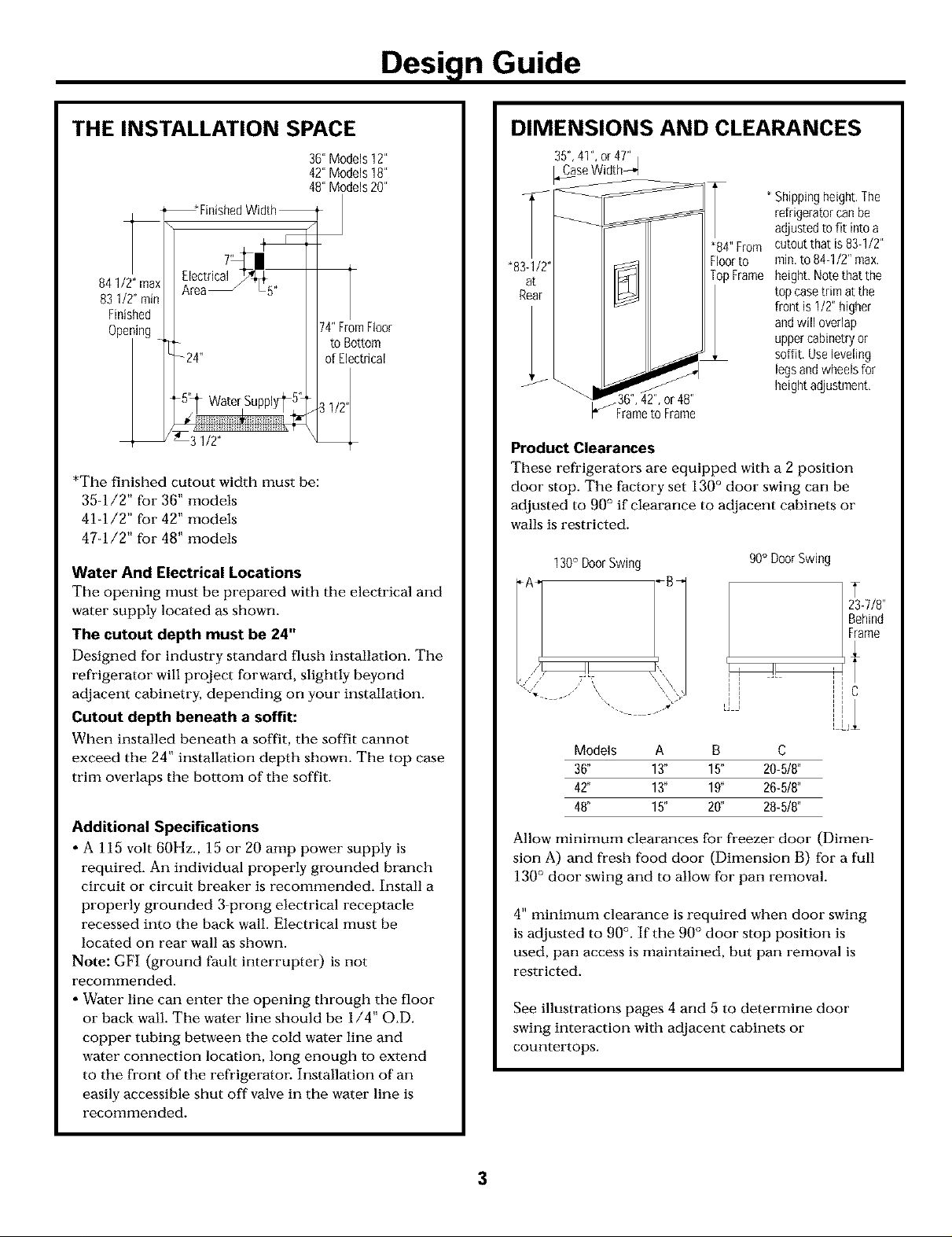
THE INSTALLATION SPACE
36"Models12"
42"Models18"
48"Models20"
_*FinishedWidth_
841/2"max
83 1/2"min
Finished
Ope_
*The finished cutout width must be:
35-1/2" for 36" models
41-1/2" for 42" models
47-1/2" for 48" models
Water And Electrical Locations
The opening must be prepared with the electrical and
water supply located as shown.
The cutout depth must be 24"
Designed for industry standard flush installation. The
refrigerator will project forward, slightly beyond
adjacent cabinetry, depending on your installation.
Cutout depth beneath a soffit:
When installed beneath a soffit, the soffit cmmot
exceed the 24" installation depth shown. The top case
trim overlaps the bottom of the soffit.
Additional Specifications
, A 115 volt 60Hz., 15 or 20 amp power supply is
required. An individual properly grounded branch
circuit or circuit breaker is recommended. Install a
properly grounded 3-prong electrical receptacle
recessed into the back wall. Electrical must be
located on rear wall as shown.
Note: GFI (ground fault interrupter) is not
recommended.
• Water line can enter the opening through the floor
or back wall. The water line should be 1/4" O.D.
copper tubing between the cold water line and
water connection location, long enough to extend
to the front of the refrigerator. Installation of an
easily accessible shut off valve in the water line is
recommended.
74"FromFloor
to Bottom
of Electrical
DIMENSIONS AND CLEARANCES
35",41",or4T'
_,_aseWidth_,d
Shippingheight,The
refrigeratorcanbe
adjustedto fit intoa
cutoutthat is83-1/2"
"83-1/2" Floorto
at TopFrame
Rear
A
or48"
_" Frameto Frame
Product Clearances
These refrigerators are equipped with a 2 position
door stop. The factory set 130 ° door swing can be
adjusted to 90° if clearance to adjacent cabinets or
walls is restricted.
Models A B C
36' 13" 15" 20-5/8"
42" 13" 19' 26-5/8"
48" 15" 20' 28-5/8"
Allow minimum clearances for freezer door (Dimen-
sion A) and fresh food door (Dimension B) for a full
130° door swing and to allow for pan removal.
4" minimum clearance is required when door swing
is adjusted to 90 °. If the 90 ° door stop position is
used, pan access is maintained, but pan removal is
restricted.
See illustrations pages 4 and 5 to determine door
swing interaction with adjacent cabinets or
countertops.
rain,to 84-1/2"max,
height,Notethat the
top casetrimatthe
front is 1/2"higher
andwill overlap
uppercabinetryor
soffit, Useleveling
legsandwheelsfor
heightadjustment,
90° DoorSwing
i
l
23-7/8"
Behind
Frame
3
Page 4
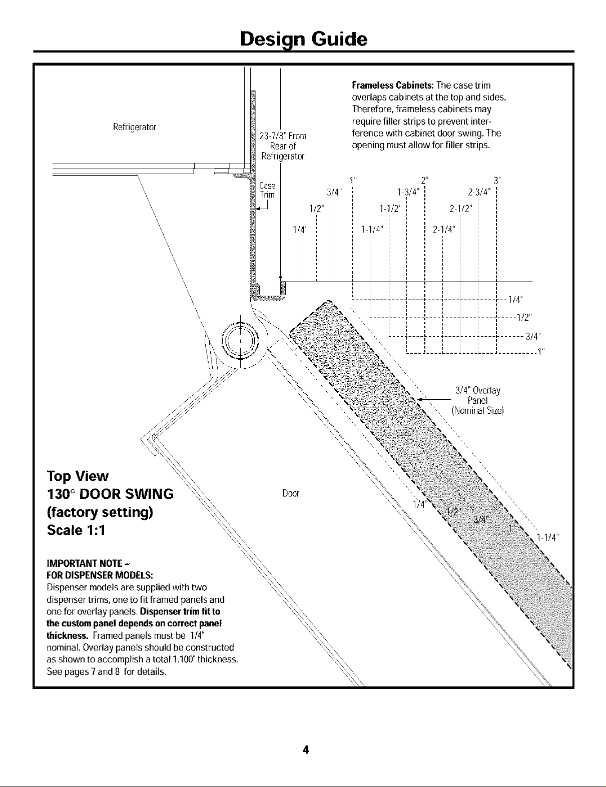
Refrigerator
Design Guide
FramelessCabinets:The case trim
overlaps cabinets atthe to ) and sides.
Therefore, frameless cabinets may
23-7/8"From
Rearof
Refrigerator
ference with cabinet door swing. The
opening mustallow for filler strips.
require filler strips to prevent inter-
4\
\
\
\
\
\
\
\
\
\
\
\
\
\
\
\
\
\
\
\
\
\
\
Case
_m
1/2"
1/4"
1 " 2"
3/4"
1-1/4"
1-3/4" 2-3/4"
I
1-1/2" I 2-1/2"
2-I/#'
i i
i i
3_
3/4"Overlay
Panel
_]ominalSize
\
Top View
130 ° DOOR SWING
(factory setting)
Scale 1:1
IMPORTANTNOTE -
FORDISPENSERMODELS:
Dispensermodels are supplied with two
dispenser trims, one to fit framed panels and
one for overlay panels. Dispensertrim fit to
thecustompanel dependson correctpanel
thickness. Framedpanels mustbe 1/4"
nominal. Overlay panels should be constructed
as shown to accomplish a total 1.100°thickness.
and 8 for details.
\
Door
Page 5

Design Guide
Refrigerator
\
\
\
\
FramelessCabinets:
Thecase trim overlaps
cabinets at the top
and sides.
Therefore, frameless
_Case #im
cabinets may require filler
strips to prevent inter-
ference with cabinet door
swing. Theopeningmust
allow for filler strips,
23-7/8"
FromRearof
Refri{erator
\
\
\
\
\
\
\
\
\
\
\
\
\
\
\
\
\
\
\
\
i i i
.... I/2
r
3/4"
Top View
90 ° DOOR SWING
(optional setting)
Scale 1:1
IMPORTANTNOTE-
FORDISPENSERMODELS:
Dispensermodels are supplied with
two dispenser trims, one to fit framed
panels and one for overlay panels.
Dispensertrimfit tothecustom
paneldependsoncorrectpanel
thickness. Framedpanels mustbe
1/4"nominal. Overlay panelsshould
be constructed asshown to accom-
plish a total 1.100°thickness. See
pages 7and 8 for details.
1-1/4"
1-1/2"
Door
3/4" Overlay
Panel
(NominalSize)
1-1/4"
Page 6

Design Guide
CUSTOMIZATION BASICS:
Framed Or Overlay Panels, Custom Handles and Accessory Kits
Stainless Steel Wrapped Models
36" wide models- ZISS360N, ZISS360D
42" wide models =ZISS420N, ZISS420D
48" wide models =ZISS480N, ZISS480D
Trimmed Models
36" wide models- ZIS360N, ZISB360D, ZISW360D
42" wide models- ZIS420N, ZISB420D, ZISW420D
48" wide models- ZIS480N, ZISB480D, ZISW480D
Stainless Steel Wrapped Refrigerators
Stainless Steel wrapped refrigerators have wrapped
doors and grille panel, beveled edges, and tubular
stainless steel handles that coordinate with other
Monogram appliances. These models are shipped
ready for installation.
Trimmed Refrigerators
Trimmed refrigerators are designed to be customized
with decorative panels. Field installed custom door and
grille panels are required.
Framed panels
You may install 1/4" thick custom panels from your
cabinet manufacturer. The decorative panel slides into
the factory installed trim. Or, order black, white and
stainless steel accessory panels from your Monogram
dealer.
Overlay panels
You may also choose to install custom overlay panels
from your cabinet manufacturer. This design provides a
seamless appearance which integrates smoothly with
surrounding cabinetry.
/
3/4" OverlayPanel
,10"ThickSpacerPanel
1/4"ThickBackerPanel
Standard supplied handles shown in314"overlay panel position.
Door Handles
The standard supplied handles can be adjusted to
accommodate both framed or overlay panels. Custom
handles of your choice, supplied by your cabinet maker
can also be installed. If desired, you may order ZKHSS2
Monogram stainless steel tubular handle kit for overlay
panels.
StandardDoorHandles
/
FramedPanel
StandardDoorHandles
Standardsupplied handles shown in I14"panel position.
Optional Accessory Kits
ZKHSS2: Monogram Tubular Stainless Steel handles
designed to fit overlay panels.
Accessory Panels
White, black and stainless steel accessory panels are
available from your Monogram dealer. Panels are cut to
size and ready to install.
Side Panels
Side panels must be used whenever the sides of the
refrigerator will be exposed.
ZISW480D ZPW480D ZPS480D
ZtS480N ZPW480N ZPB480N ZPS480N
ZlSB420D ZPB420D ZPS420D
ZlSW360D ZPW360D ZPS360D
ZIS360N ZPW360N ZPB360N ZPS360N
6
Page 7

Design Guide
1/4" FRAMED PANEL DIMENSIONS
If you choose to install framed panels, they must be
cut to the dimensions shown. The panels will slide
into the frame on the door and grille.
Non-Dispenser Models
If the custom panel is less than 1/4" thick and it fits
loosely in the door frame it can be backed up with
a piece of filler material or foam tape to improve
the fit.
IMPORTANT NOTE - Dispenser Models
The refi'igerator is supplied with two dispenser trims,
one for framed panels and one for overlay panels.
• If the panel is less than 0.250" thick a noticeable
gap may be created around the dispenser trim.
Foam tape may be applied on the door to improve
the fit.
|_ 5/16"
Door
I
I
I
IMPORTANTNOTE:Maximum weight for fresh food panel is
50pounds and 30pounds for freezer panel.
• If the panel is more than 0.250" thick, the
dispenser trim cannot be secured to the door.
See Dispenser Trim Fit Example, page 9.
k Trim
Reveal
_1/4"
Panel
GrillePanel
DispenserF
Cutout
Freezer FreshFood 1
Panel Panel
_U_ _E_
T
C
/
DispenserCutout
The framed panel must be 114"nominal thickness
to fit the dispenser trim.
15-3/8"
1
_'_ 94/8" _'_
36"Models 33-7/8 9 68-3/8 14-9/16 18-9/16
42"Models 39-7/8 9-112 68-3/8 14-9/16 24-9/16
48"Models 45-7/8 9-1/2 68-3/8 18-9/16 26-9/16
7
Page 8

Design Guide
3/4" OVERLAY PANEL DIMENSIONS
For a more custom appearance, overlay panels may be
installed on trimmed models. The overlay panel must
be secured to a 1/4" thick backer panel which slides
into the trim. A spacer panel 0.10" thick must be placed
between the overlay and backer panel.
Assemble the panels with glue and screws.
• Center the spacer panel on the backer panel, left to
right and top to bottom. Secure the panels with glue.
• Center the spacer and backer panel on the overlay
panel and secure with glue and screws. Screws must be
countersunk into the backer panel.
IMPORTANT NOTE - Dispenser Models
The refrigerator is supplied with two dispenser trims,
one for framed panels and one for overlay panels.
The overlay dispenser trim is designed to fit a total
panel thickness of 1.100".
• If the panel is less than 1.100" a noticeable gap may
be created around the dispenser trim.
• If the panel is more than 1.100" the dispenser trim
cannot be secured to the doog
See Dispenser Trim Fit Example, page 9.
Door
Ov
P,
114"
Backer_
Panel
.250"+ .10" + .750"= 1.100"TotalPanelThickness
• The overlay panel must be constructed according to
the specifications shown to achieve the correct total
thickness.
• Alternative panel construction methods such as
securing a 3/4" panel to a 1/4" backer panel cannot
be used. Another method, routing a 3/4" thick panel
on all sides cannot be used. These methods will not
result in the required 1.100" panel thickness.
When a raised panel design is to be used, a custom
middle rail is required. See page 9 for details.
S}acer
NOTE:Left-to-right offset
is not always equal to
top-to-bottom offset.
GrillePanel
F
CuLout
Dispense_
/
Freezer :reshFood1
Panel Panel
!
IMPORTANTNOTE:Maximum
total weight for assembledfresh
food panel is50 poundsand30
pounds for freezer panel.
Dispenser Cutout
B
L
36"!
C
1/4"BackerPanel
.10"SpacerPanel
314"OverlayPanel
42"!
1/4"BackerPanel
.10"SpacerPanel
314"OverlayPanel
48"!
1/4"BackerPanel
.10"SpacerPanel
3/4"OverlayPanel
*Cutthe dispenser opening after the backer, spacer and overlay
panelshave been assembled.
33-7/8 9 68-3/8 14-9/16 18-9/16
33 8-3/8 67 13-1/4 17-1/4
34-1/8 9-1/4 68-5/8 14-13/16 18-13/16
39-7/8 9-1/2 68-3/8 14-9/16 24-9/16
39 8-5/8 67 13-1/4 23-1/4
40-1/8 9-3/4 68-5/8 14-13/16 24-13/16
45-7/8 9-1/2 68-3/8 18-9/16 26-9/16
45 8-5/8 67 17-1/4 25-114
46-1/8 9-3/4 68-5/8 18-13/16 26-13/16
8
Page 9

Design Guide
DISPENSER MODELS:
RAISED OVERLAY PANEL DESIGN
When a raised panel design is to be used, a
custom wide middle rail is required to accept
the dispenser trim.
*The middle rail must be wide enough to allow
for the dispenser trim to overlap the opening.
*The middle rail must be 1.100" total thickness
to accept the dispenser trim.
16-3/4"
J
Dispenser
Trim
_10-5/8'2_,
1/4"BackerPanel
,10"Spacer
DISPENSER TRIM FIT EXAMPLES:
(NOT TO SCALE)
1/4" FRAMED PANEL
, The dispenser trim fits over the
custom panel and snaps into the
freezer door.
*The clips will not engage the door if
the panel is more than 0.250" thick.
*If the panel is less than 0.250" thick, a
noticeable gap may be created around
the dispenser trim.
3/4" OVERLAY PANEL
, The dispenser trim fits over the
custom panel and snaps into the
freezer door.
*The clips will not engage the door if
the panel is more than 1.100" thick.
*If the panel is less than 1.100" thick, a
noticeable gap may be created around
the dispenser trim.
1/4"
Framed
1/4"Backer Panel
FREEZERDOOR
0.250"
Thick
1/4"Dispenser Trim
FREEZERDOOR
1.100"
TotalThickness
314"Overlay Dispenser Trim
9
Page 10

Design Guide
SIDE PANELS
Side panels must be used
whenever the sides of the
refrigerator will be ex-
posed. The 1/4" side
panels will slip into the side
case trim. Order the side
panels from the cabinet
manufacturer.
* Depending on
installation height.
TOOLS REQUIRED
• Tinsnips to cut banding
• Stepladder
• Bucket
• Level
• Appliance Hand Truck
• Tubing cutter
• 7/16" open-end wrench
• #2 Phillips screwdriver
• Drill and appropriate bits
• 5/16", 7/16" socket
• Safety glasses
• 1-1/4" open end wrench
• Pliers
*84"
2-9/16"
FLOORING
For proper installation, this refrigerator must be
placed on a level surface of hard material that is at
the same height as the rest of the flooring. This
surface should be strong enough to support a fully
loaded refrigerator, or approximately 700 lbs.
NOTE: Protect the finish of the flooring. Cut a large
section of the cardboard carton and place under the
refrigerator where you are working.
GROUNDING THE REFRIGERATOR
IMPORTANT - (Please read carefully)
FOR PERSONAL SAFETY, THIS APPLIANCE MUST
BE PROPERLY GROUNDED.
The power cord of this appliance is equipped with a
three-prong (grounding) plug which mates with a
standard three-prong (grounding) wall receptacle to
minimize the possibility of electric shock hazard from
this appliance.
Have the wall outlet and circuit checked by a quali-
fied electrician to make sure the outlet is properly
grounded.
Where a standard 2-prong wall outlet is encountered,
it is your personal responsibility and obligation to
have it replaced with a properly grounded 3-prong
wall outlet.
HARDWARE SUPPLIED
• Water filter bypass plug
• Anti-Tip brackets
• 1/4" nut and ferrule
• Dispenser trims for 1/4" and 3/4" overlay panels
MATERIALS REQUIRED
• 35" long 2x4 for Anti-Tip support.
• Copper water line tubing
• Water shut-off valve (optional but recommended)
• Custom panels for doors and grille panel
• Screws to secure refrigerator to cabinetry.
• Stick-on hook and loop fastener strips for
1/4" side panels
DO NOT, UNDER ANY
CIRCUMSTANCES, CUT
OR REMOVE THE THIRD
(GROUND) PRONG
FROM THE POWER CORD.
DO NOT USE AN ADAPTER PLUG TO CONNECT
THE REFRIGERATOR TO A 2-PRONG OUTLET.
DO NOT USE AN EXTENSION CORD WITH THIS
APPLIANCE.
10
Page 11

Installation Instructions
[STEP 11REMOVE PACKAGING
CAUTION:Refrigeratorismuch heavieratthe
top thanatthebottom - be carefulwhen moving.
When using a hand truck, handle from side only.
PRUDENCE:Le r0frig6rateur est beaucoup plus
lourd en haut qu'en bas. Ii faut 6tre prudent lots des
d0placements. Si un diable est utilis0, il faut soulever
le rOfrig0rateur sur le c6t6 seulement.
• Carefully cut banding at the top and bottom, remove
outer carton.
• Slide out back corner posts (2).
• Slide carton off top of cabinet.
NOTE: IT IS NOT NECESSARY TO LAY CABINET
DOWN IN ORDER TO REMOVE SKID!
• The unit is secured to the skid with 4 slotted tie-down
straps. Remove the four 5/16" bolts from the base
channels in the tie-downs.
STEP 2] INSTALL WATER LINE
• Remove the four 7/16"
bolts securing the straps
to the skid.
CAUTION:DO
NOT ATTEMPT TO
ROLL UNIT OFF SKID.
Remove
TieDowns
• Support blocks on the bottom of the refrigeration
case must be removed before sliding unit off skid or
damage will occur. Carefully, tilt refrigerator and
slide blocks out from beneath, slide unit off skid.
• Remove toekick, set aside for final installation.
PRUDENCE:ic
NE FAUT PAS ESSAYER
DE FAIRE ROULER LE
RI_FRIGI_RATEUR POUR
L'ENLEVER DE LAY
PALETTE.
• A cold water supply is required for automatic ice-
maker operation. The water pressure must be be-
tween 40 and 120 p.s.i.
• Route 1/4" OD copper tubing between house cold
water line and the water connection location.
• Copper tubing should be long enough to extend to
the front of the refrigerator. Allow enough tubing to
accommodate bend leading into the water line
connection.
Shut off tile main water supply.
Turn on the nearest faucet long enough to clear the
line of ware1:
• Install a shut-off valve between the icemaker water
valve and cold water pipe in a basement or cabinet.
The shut-off valve should be located where it will be
easily accessible.
NOTE: It is best to install the valve into a vertical water
pipe. If you install the valve into a horizontal water
pipe, make the connection at the top or side, to
avoid drawing off any sediment from the water pipe.
• Drill a 1/4" hole in the water pipe.
• Fasten the shut-off valve to the pipe with pipe clamp.
• Tighten the clamp screws until the sealing washer
begins to swell. Do not over tighten.
• Place a compression nut and ferrule (sleeve) onto the
end of the tubing and connect it to the shut-off valve.
Make sure the tubing is fully inserted into the valve
and ferrule is tightened.
• Turn on the main water supply and flush debris. Run
about a quart of water through the tubing into a
bucket. Shut off water supply at the shut-off valve.
/
CopperTubingJ
SaddleType
OutletVaNe
NOTE: Saddle type shut-off valves are included in
many water supply kits. Before purchasing, make sure
a saddle type valve complies with your local plumbing
codes.
NOTE: Commonwealth of Massachusetts Plumbing I
Codes 248CMR shall be adhered to. Saddle valves
are illegal and use is not permitted in Massachusetts.
Consu t with your icensed p umber.
Floor
CompressionNut
\
Ferrule
(Sleeve)
11
Page 12

Installation Instructions
[STEP 2A] WATER LINE
INSTALLATION WITH A REVERSE
OSMOSIS SYSTEM
Skip this step when not using an RO System
If the water supply to the refrigerator is from a
Reverse Osmosis Water System use the refrigerator's
filter bypass plug. Using the refrigerator's water
filtration cartridge with the RO filter can result in
hollow ice cubes.
i
[STEP 41INSTALL ANTI-TIP
BRACKETS
WARNING:ANTI-TIPPRECAUTIONS
The refrigerator is top-heavy and must be secured to
prevent the possibility of tipping forward.
ATTENTION:PRECAUTIONS CONTRE LES
BASCULEMENTS
Le r_frig_rateur est beaucoup plus Iourd en haut et il
faut le maintenir en place pour Oviter la possibilitO de
son basculement vers l'avant.
• Cut a 2" x 4" block, 35" long and secure the block to
the mounting brackets provided using #12 or #14
wood screws.
2x4Cut _
35"Length
Installation Mounting
Height Bracket
FromFloor
7 7_--
[STEP 3_ INSTALL SIDE PANELS
Skip this step when not using side panels
If you are using 1/4" side panels, they should be
inserted into the case trim. Fasten the panels to the
refrigerator with stick-on hook and loop fastener
strips before setting refrigerator in place.
ScrewsMountedinto_
VerticalWall Studs
• Secure the bracket with wood block to the back wall
so that it is 84" (or your installation height) from the
finished flool: Use #12 or #14 wood screws. See
illustration.
Bracke_
Required
Height
From
Floor
to
Bottom
ofWood
Block
SideView
Brackets
NotRequired
Beneatha
Soffit
• Screws must penetrate at least one inch into vertical
wall studs.
• Gently push refrigerator into the opening with
hands against front corners.
Important Note: Whenthe refrigeratoris installedundera soffit or if
thereis notenoughheightfor this methodof security,bracketscannot
beused,Proceedtostep5 to levelthe refrigeratorandthentostep 6to
securerefrigeratortocabinets.Therefrigeratormustbesecuredto
preventtipping,
12
Page 13

Installation Instructions
ISTEP 51 LEVEL REFRIGERATOR
All models have 4-point leveling. The front is sup-
ported by leveling legs, the rear is supported by
adjustable wheels. Both are accessible from the front
of the refrigerator.
• To level the back of the refrigerator, turn the 7/16"
hex nut located above the front wheels. Turn
clockwise to raise or counterclockwise to lower the
refrigerator.
• For front leveling, use a 1-1/4" open-end wrench.
• Adjust height of refrigerator to match installation
cutout opening 83-1/2" to 84q/2". The refrigerator
should be level and plumb with cabinetry.
_STEP 7] ADJUST DOOR SWING
NOTE: This refrigerator has a 2-position door stop.
When space does not allow the door to swing open
fully to 130 °, you may change the door swing to a 90 °
opening. Skip this step if door opening is satisfactory
for your installation situation.
Door
/
Hinge
[STEP 61SECURE REFRIGERATOR
TO CABINETRY
Whenever possible, perform this step for anti-tip
security, or when anti-tip brackets cannot be used.
The refrigerator must be secured to prevent tipping.
• Raise the grille panel to access case trim.
• Drill hole in trim and drive screw through the trim
into adjacent cabinet.
• Follow the same procedure on the opposite side.
ThroughCaseTrimInto
AdjacentCabinets
• Open the door to view the bottom hinge. Note the
door stop pin locations. The pin is factory installed
in the 130° position.
• Close the door. From below, use pliers to unscrew
the door stop and reinstall into the 90° position.
13
Page 14

Installation Instructions
ISTEP 81 INSTALL GRILLE PANEL
To insert framed or overlay panel into the grille:
* Raise the grille panel to stop position.
Loosen Loosen
Side Side
_im _im
Screw Screw
AdjustNutBelow
SpringtoAccomodate
PanelWeight
* Loosen screws on side trim behind frame. Remove
bottom trim.
* Slide panel over the metal backer panel and into
the trim.
* If necessary, tap with a wood block until panel slips
under the top trim piece.
* Reassemble bottom trim. Tighten screws.
* Adjust the hinge spring to accommodate the panel
weight, if necessary.
14
Page 15

Installation Instructions
[STEP INSTALL FRAMED PANELS GotoStep9A forOverlayPanels
b.
P - 4m
k
p ---
Install door panels:
• Open door to 90 °. Remove the 6 Phillips head screws
from the door handle.
• Remove handle. Retain a11 screws.
• Remove 6 screws holding trim, lift off trim. Retain
SCFOWS.
• Slide framed panel into the door trim.
Dispenser Models Only:
• The dispenser controls protrude beyond the face of the
freezer door. To avoid damage to the dispenser, the
trim at the top of the door should be removed.
• Remove the screws holding the top trim in place.
• Place the freezer panel into the bottom channel and
slide into the hinge side trim.
• Reinstall the top trim piece with screws.
Supplied
HandleShown
in 114"Panel
Position
i
Handle
[rim
¢1 . •
/Door_im
Refrigerator
Door
* There are two sets of holes in the handle side trim.
Replace handle side trim by installing the original
screws in the FRONT screw holes.
* Secure the handle to the door using the REAR screw
holes.
* Follow the same procedures to install the opposite
panel.
* Check to be sure handles are evenly aligned with each
other at the top. To adjust, loosen handle screws and
slide up or down. Tighten screws.
Custom handles
If you are using custom handles, the handle must be
properly secured to the panel before sliding the panel
into the trim.
*The cabinet manufacturer will supply the custom
handle and hardware.
* Secure the door trims using both the FRONT and
REAR screw holes. Discard supplied handles.
toSecureTrim
UseRearHoles
to SecureHandle
15
Page 16

Installation Instructions
ISTEP 9AI INSTALL OVERLAY PANELS
b. knl
- -qml
P
Install door panels:
• Open door to 90 °. Remove the 6 Phillips head screws
from the door handle.
• Remove handle. Retain a11 screws.
• Remove 6 screws holding trim, lift off trim. Retain
SCFOWS.
• Slide overlay panel into the door trim.
Handle
[rim
Forward
For3/4"
Move
Panel
/ DoorTrim
Refrigerator
Door
Supplied Handle
Shown in Overlay
PanelPosition
Dispenser Models Only:
• The dispenser controls protrude beyond the face of the
freezer door. To avoid damage to the dispenser, the
trim at the top of the door should be removed.
• Remove the screws holding the top trim in place.
• Place the assembled freezer panel into the bottom
channel and slide into the hinge side trim.
• Reinstall the top trim piece with screws.
* There are two sets of holes in the handle side trim.
Replace handle side trim by installing the original
screws in the REAR screw holes.
* Secure the handle to the door using the FRONT screw
holes.
* Follow the same procedures to install the opposite
panel.
* Check to be sure handles are evenly aligned with each
other at the top. To adjust, loosen handle screws and
slide up or down. Tighten screws.
Custom handles
If you are using custom handles, the handle must be
properly secured to the panel before sliding the panel
into the trim.
* The cabinet manufacturer will supply the custom
handle and hardware.
* Secure the door trims using both the FRONT and
REAR screw holes. Discard supplied handles.
i
J- iii:fli_i_!i'i!_
o, - - i!i!!!iil¸
/
UseFrontHoles
toSecureHandle
UseRearHoles
toSecureTrim
16
Page 17

Installation Instructions
ISTEP 101 INSTALL DISPENSER
TRIM
Skip this step is you are installing a stainless
steel wrapped or a non-dispenser refrigerator.
There are two dispenser trims shipped with your
refrigerator. Select the appropriate trim for your
application.
J
Framed
Panel
Trim
Comparethe dispenser trims. Note that the inside
depth of the frames are different. Choosethe trim
with less depth Forframed panels, choose the
deeper one Foroverlay panels.
Dispenser trim fit over the custom panel depends on
correct panel thickness. See pages 7 and 8 for panel
construction information.
Overlay
Panel
Tdm
[STEP 11] CONNECT WATER SUPPLY
Check to be sure that refrigerator power cord is not
plugged into the wall outlet.
Jl
\ Refrigerator House
_.Water Supply WaterSupp_
, Locate and bring copper tubing to the front of the
cabinet.
* Turn the water on to flush debris from line. Run
about a quart of water through tubing into a bucket,
then shut-off water.
* Slip a 1/4" nut and ferrule (provided) over both
ends of the copper tubing. Insert tube into the
union fitting on the unit and tighten nut to union.
* Turn on the water to check for leaks.
I -
, Press and snap the dispenser trim into the dispenser
recess on the refrigerator door.
If an excessive gap exists around the dispenser trim or
if the panel fits loosely in the door frame, foam tape
may be applied to help improve the fit. Remove the
trim and panel and apply foam tape to the door
around the dispenser and in the corners.
Note: Make sure excess tubing length does not
interfere with toekick installation.
17
Page 18

Installation Instructions
ISTEP 121 CONNECT POWER
• Connect refrigerator power cord plug to a properly
grounded receptacle, accessible through the top of
the grille opening.
RaiseIr?_l I
GrilleIJ/ Gill !
P_
• Check to make sure power to refrigerator is on by
opening refrigerator door to see if interior lights
are on.
• The temperature controls are preset at 37°F for the
fresh food section and 0°F for the freezer.
• Allow 24 hours to stabilize before making
adjustments.
[STEP 13] START ICEMAKER
[STEP 14] INSTALL TOEKICK
• Locate the supplied toekick (shipped taped to
the side of the refrigerator). Install with 2 screws
provided, adjust to desired height and tighten screws.
• k custom toekick can be installed to match or
complement the surrounding cabinetry. Use the
supplied toekick as a template to cut the shape.
Supplied Toekick
__J
0,
"%
1/4" or Thicker Toekick
-%
INSPECT FINAL INSTALLATION
Check door alignment
Stand back away from the refrigerator to inspect the
final installation.
• Check to be sure handles are evenly aligned with
each other at the top. To adjust, loosen handle
screws and slide up or down. Tighten screws.
• During shipping or the addition of heavy door
panels may have caused the doors to move slightly
out of alignment.
3wetLight
• Flip the switch to I (ON). The icemaker will begin
operation automatically.
• Be sure nothing interferes with the sweep of the
feeler arm.
• Discard the first full bucket of ice cubes.
• To turn the icemaker off, set the switch to O (OFF).
'DoorOutof
Alignment
Bushing
/
• If necessary, the fresh food door may be adjusted
up or down to align with the freezer door.
• Use a 5/16" wrench to adjust the hinge pin as
shown.
18
Page 19

Notes
19
Page 20

bg o. 49-60138-1
•No. 164D4373P001
(ND 429)2/02
3546001
Note: While performing installations described in this book,
safety glasses or goggles should be worn,
For Monogram _ local service #1 your area, call
1-800-4441845.
Note: Product improvement is a continuing endeavor at
Ceileral Electric. Therefore, materials, appearance and
specifications are subject to change without notice.
O
Monogram;'
Webring good things to life.
General Electric Company
Loutsvffle, KY40225
 Loading...