

Page 1

These Monogram refrigerators and
freezers are designed to be customized
with decorator door and grille panels.
Field installed panels are required.
Custom Options Guide and
Installation
Instructions
With Custom Panel Dimensions
and Trim Kit Installation Instructions
Factory installed trim will
accommodate 1/4" thick custom
panels or optional Lexan ®and stainless
steel panel kits.
Optional trim kits allow an even
broader range of custom appearance
options.
Read this booklet carefu!lg to
accomplish the desired appearance and
to insure a trouble free installation.
This booklet contains information and
illustrations to demonstrate custom
possibilities. Custom door and grille
panel sizes vary to accommodate the
kit being used. Dimensions for each
application are included and can
be faxed or sent to the cabinet
manufacturer so that the panels
can be constructed accuratelg.
36" Refrigerators and 36" Freezers
ZIR36N LH -All Refrigerator
ZlR36N RH - All Refrigerator
ZlF36N LH -All Freezer
ZIF36N RH - All Freezer
monogram.corn
Page 2
Before you begin - Read these instructions completely and carefully.
IMPORTANT - Save these instructions for local inspector's use.
IMPORTANT - OBSERVE ALL GOVERNING CODES AND ORDINANCES.
Note to Installer - Be sure to leave these instructions with the Consumen
Note to Consumer - Keep these instructions with your Owner's Manual for future reference.
This appliance must be properly grounded. See "Grounding the
Refrigerator," page 12.
Cet appareil dolt _tre correctement mis 6 la terre. Consulter <<Mise 6terre du r_frig_rateur >>,page 12.
If you received a damaged product, you should
immediately contact your dealer or builden
Proper installation is the responsibility of the installen
Product failure due to improper installation is not
covered under the GEAppliance Warranty. See the
Owners' Manual for warranty information.
For Monogram local service in your area,
1.800.444.1845.
Use this appliance only for its intended purpose.
Immediately repair or replace electric service
cords that have become frayed or damaged.
Unplug the refrigerator before cleaning or
making repairs.
Repairs should be made by a qualified service
technician.
For Monogram service in Canada,
1.800.561.3344
For Monogram Parts and Accessories,
call 1.800.626.2002.
• II ne faut utiliser cet appareil que pour rusage
pour lequel il a _t_ construit.
• II faut r@arer ou remplacer imm_diatement tout
cordon d'alimentation _lectrique effiloch6 ou
Due to the weight and size of this refrigerator, and
to reduce the risk of personal injury or damage to
the product - THREE PEOPLE ARE REQUIRED FOR
PROPER INSTALLATION.
endommag&
• D6brancher le rdrig_rateur avant le nettoyage
ou toute intervention.
• Les r_parations doivent _tre faites par un
technicien qualifi_.
Contents
cause du poids et de la taille de ce r6frig_rator
et pour r_duire le risque de blessure et de
dommages, IL FAUT TROIS PERSONNES POUR
FAIRE L'INSTALLATION CORRECTEMENT.
Design Information
Flush or Semi-Flush Enclosure Installations ..................3
Enclosure Cutout and Product Dimensions ....................3
Clearances ......................................................................................4
Side By Side Installation of Freezer
and Refrigerator ..........................................................................4
Installation Examples ............................................................4, 5
Frameless Cabinets ....................................................................5
Accessory Panel Kits ..................................................................5
Advance Planning Appearance Options ..........................5
Models Available ..........................................................................6
Trim Kit Descriptions ..................................................................6
Custom Panel Dimensions
Product and Cutout Information ..........................................7
1/4" Thick Custom Panels on 1/4" backing ....................8
3/4" Thick Panels with Supplied Handle ..........................9
3/4" Thick Panels with Custom Handle ..........................10
Side Panel or Filler Options ..................................................11
Trim Kits
ZGC2 Trim Kit, Grille Panel Frame Adjustment ..........19
ZKHR1 Trim Kit (for 1/4" Panels),
Support for Custom Handles ....................................20-21
ZKTR36LH/ZKTR36RH Trim Kit,
3/4" Custom Panels ......................................................22-25
ZKHTR1 Trim Kit (for 3/4" Panels),
Support for Custom Handles ....................................26-28
ZKHRSS1 Trim Kit (for 1/4" Panels),
Tubular Stainless Steel Handles ..............................29-32
ZKHTRSS1 Trim Kit (for 3/4" Panels),
Tubular Stainless Steel Handles ..............................33-34
ZUG75 Trim Kit, Unified 3/4" Grille Panel Kit ......35-40
Installation Instructions ................................................12-18
Page 3
Flush or
Semi-Flush
Enclosure
Installations
Design Information
36" Refrigerators, Freezers
Advance Planning
Enclosure
Cutout and
Product
Dimensions
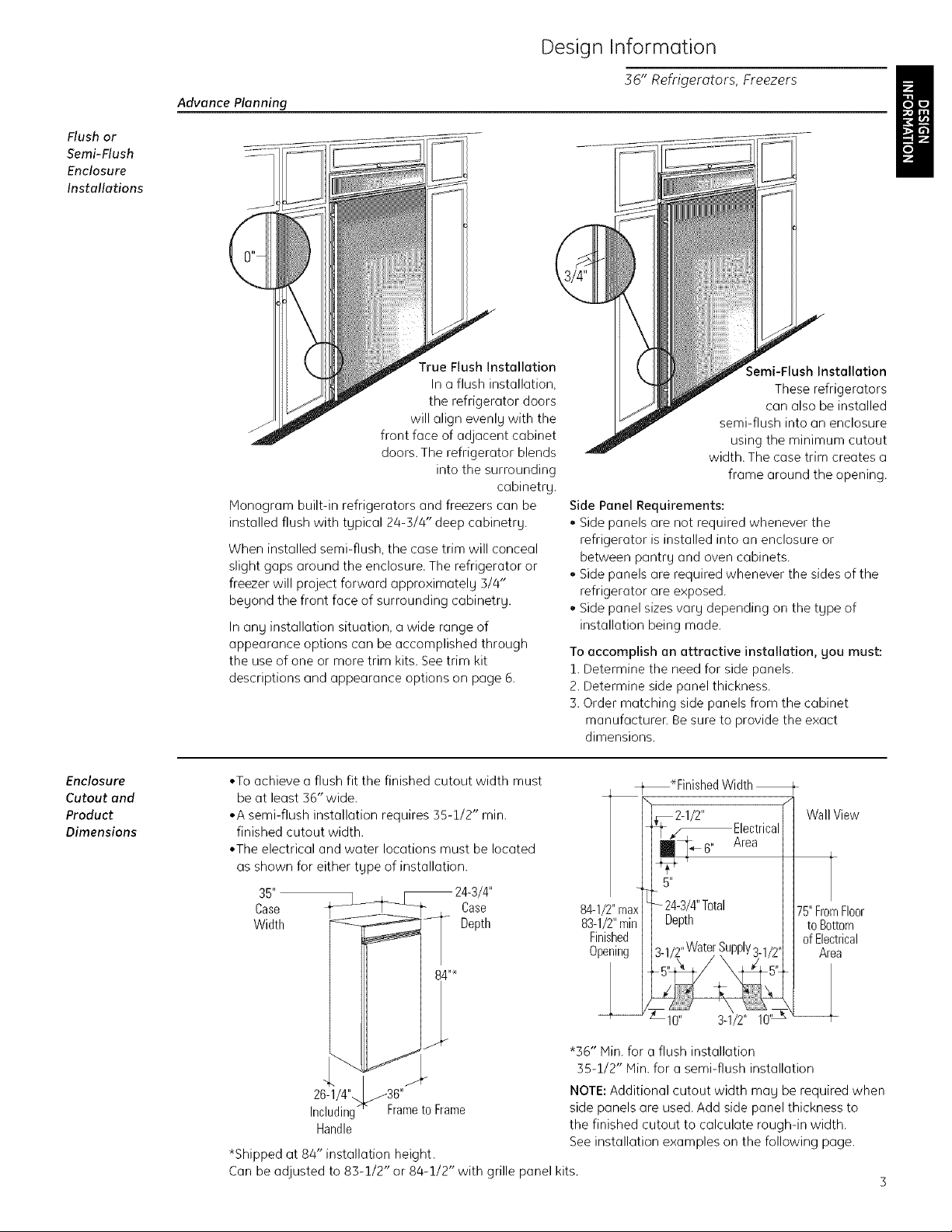
True Flush Installation
In a flush installation,
the refrigerator doors
will align evenlg with the
J front face of adjacent cabinet
doors. The refrigerator blends
into the surrounding
cabinetrg.
Monogram built-in refrigerators and freezers can be
installed flush with tgpical 24-5/4" deep cabinetry.
When installed semi-flush, the case trim will conceal
slight gaps around the enclosure. The refrigerator or
freezer will project forward approximatelg 5/4"
beyond the front face of surrounding cabinetrg.
In ang installation situation, a wide range of
appearance options can be accomplished through
the use of one or more trim kits. See trim kit
descriptions and appearance options on page 6.
• To achieve a flush fit the finished cutout width must
be at least 56" wide.
oA semi-flush installation requires 55-1/2" min.
finished cutout width.
°The electrical and water locations must be located
as shown for either type of installation.
35" /4"
Case Case
Width Depth
;emi-Flush Installation
These refrigerators
can also be installed
semi-flush into an enclosure
using the minimum cutout
width. The case trim creates a
frame around the opening.
Side Panel Requirements:
,, Side panels are not required whenever the
refrigerator is installed into an enclosure or
between pantr U and oven cabinets.
. Side panels are required whenever the sides of the
refrigerator are exposed.
Side panel sizes var U depending on the tgpe of
installation being made.
To accomplish an attractive installation, you must:
1. Determine the need for side panels.
2. Determine side panel thickness.
3. Order matching side panels from the cabinet
manufacturen Be sure to provide the exact
dimensions.
-t_*Finished Width
_2-1/2" fl Wall View
L_ _Electrical II
84-1/2"max
83-1/2"min
Finished
Opening
2434 Ttal
- / " 0 1175" FromFloor
uepth I I to Bottom
...... II of Electrical
3-1,/2"water ,bupply3-1/2,H Area
*Shipped at 84" installation height.
Can be adjusted to 83-1/2" or 84-1/2" with grille panel kits.
*B6" Min. for a flush installation
35-1/2" Min. for a semi-flush installation
NOTE: Additional cutout width mug be required when
side panels ore used. Add side panel thickness to
the finished cutout to calculate rough-in width.
See installation examples on the following page.
Page 4
Design Information
36" Refrigerators, Freezers
Clearances
1
90° Door Swing /
130°D00rswing[ %'1°
!' i36-3/4"
130° ',.y
4"_Min.
to Wall
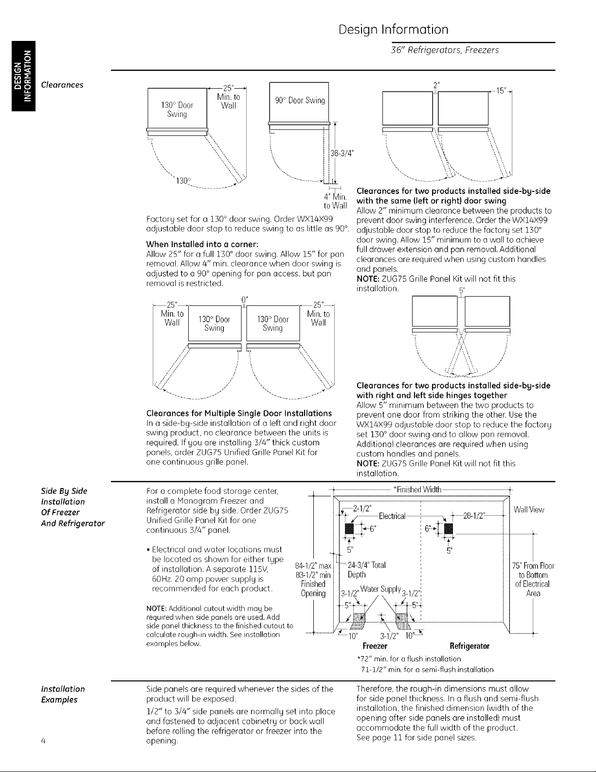
Factory set for a 150 ° door swing. Order WX14X99
adjustable door stop to reduce swing to as little as 90°.
When Installed into a corner:
Allow 25" for a full 130 ° door swing. Allow 15" for pan
removal. Allow 4" rain. clearance when door swing is
adjusted to a 90 ° opening for pan access, but pan
removal is restricted.
0 _
%%
Wa
130° Door m 130° Door
Swing m Swing
4 I',
z:ffx "::::-:::,,,,
::::::::z
///
,( ," ',3-"
_q
II
q-' '-F
i
/
/
Z
Clearances for Multiple Single Door Installations
In a side-by-side installation of a left and right door
swing product, no clearance between the units is
required. If you are installing 3/4" thick custom
panels, order ZUG75 Unified Grille Panel Kit for
one continuous grille panel.
--25"--
Min. to
Wall
"X
",',,
2 _
\,,',,,[ '_,',
', \
..... *,, ,,,
Clearances for two products installed side-by-side
with the same (left or right} door swing
Allow 2" minimum clearance between the products to
prevent door swing interference. Order the WX14X99
adjustable door stop to reduce the factory set 130 °
door swing. Allow 15" minimum to a wall to achieve
full drawer extension and pan removal. Additional
clearances are required when using custom handles
and panels.
NOTE: ZUG75 Grille Panel Kit will not fit this
installation. 5"
!
3'
/
", .... X/
ft '
x-.... .......,
Clearances for two products installed side-bg-side
with right and left side hinges together
Allow 5" minimum between the two products to
prevent one door from striking the othel: Use the
WX14X99 adjustable door stop to reduce the factory
set 150 ° door swing and to allow pan removal.
Additional clearances are required when using
custom handles and panels.
NOTE: ZUG75 Grille Panel Kit will not fit this
installation.
Side By Side
Installation
Of Freezer
And Refrigerator
Installation
Examples
For a complete food storage center,
install a Honogram Freezer and
Refrigerator side by side. Order ZUG75
Unified Grille Panel Kit for one
continuous 5/4" panel.
, Electrical and water locations must
be located as shown for either type
of installation. A separate 115V,
60Hz. 20 amp power suppl U is
recommended for each product.
NOTE: Additional cutout width may be
required when side panels are used. Add
side panel thickness to the finished cutout to
calculate rough-in width. See installation
examples below.
Side panels are required whenever the sides of the
product will be exposed.
1/2" to 5/4" side panels are normally set into place
and fastened to adjacent cabinetry or back wall
before rolling the refrigerator or freezer into the
opening.
f _FinishedWidth
84-1/2" maxI_- 24-3/4" Total !
83-1/2"rain I I Depth
Finished II , _ , i
Opening I I I-1/2"vvate_,bupP'Y3-1/2";
_2 3-I/2" 10'_
1_2-1/2" i
I_ _Electrical% _28-1/2 '_
Freezer Refrigerater
*72" rain. for a flush installation
7:[-:[/2" rain. for a semi-flush installation
Therefore, the rough-in dimensions must allow
for side panel thickness. In a flush and semi-flush
installation, the finished dimension (width of the
opening after side panels are installed) must
accommodate the full width of the product.
See page 11 for side panel sizes.
WallView
75"FromFloor
toBottom
ofElectrical
Area
Page 5
Design Information
36" Refrigerators, Freezers
Installation
Between
Base and
Wall Cabinets
Installation
At End-of-Run
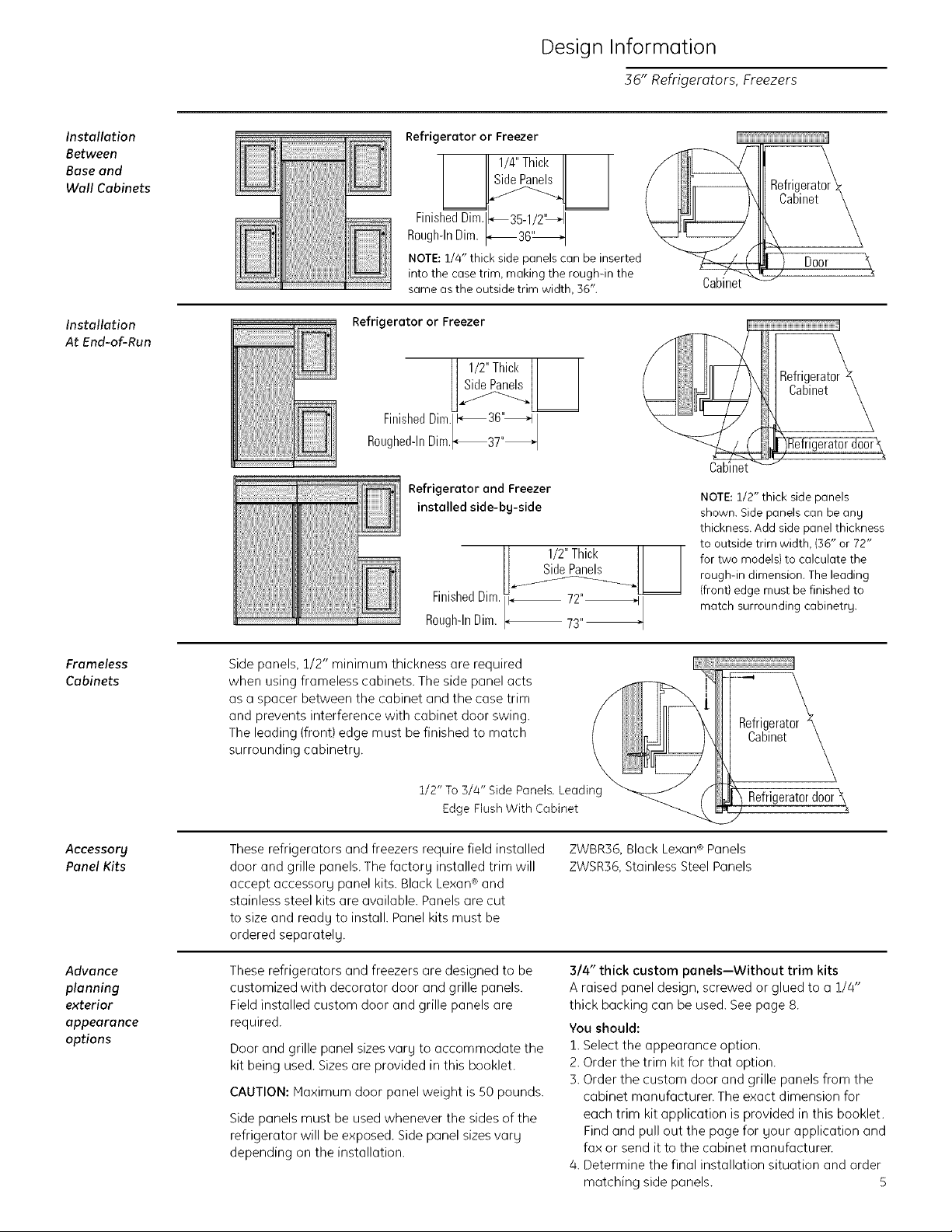
Refrigerator or Freezer
R°ugh-lnFinishedDim[lDim._ I_1
NOTE: 1/4" thick side panels can be inserted
into the case trirn, making the rough-in the
same as the outside trim width, 36".
Refrigerator or Freezer
Refrigerator and Freezer
installed side-bg-side
P
Cabi,n
Cab
NOTE: 1/2" thick side panels
shown. Side panels can be ang
thickness. Add side panel thickness
to outside trim width, (36" or 72"
for two models} to calculate the
rough-in dimension. The leading
(front} edge must be finished to
rnatch surrounding cabinetry.
Frameless
Cabinets
Accessory
Panel Kits
Advance
planning
exterior
appearance
options
Side panels, 1/2" minimum thickness are required
when using frameless cabinets. The side panel acts
as a spacer between the cabinet and the case trim
and prevents interference with cabinet door swing.
The leading (front) edge must be finished to match
surrounding cabinetrg. _.
1/2" To 3/4" Side Panels. Leading _
Edge Flush With Cabinet
These refrigerators and fi-eezers require field installed
door and grille panels. The factorg installed trim will
accept accessorg panel kits. Black Lexan ®and
stainless steel kits are available. Panels are cut
to size and readg to install Panel kits must be
ordered separatelg.
These refrigerators and freezers are designed to be
customized with decorator door and grille panels.
Field installed custom door- and grille panels are
required.
Door and grille panel sizes varg to accommodate the
kit being used. Sizes are provided in this booklet
ZWBR36, Black Lexan®Panels
ZWSR36,Stainless Steel Panels
3/4" thick custom panels--Without trim kits
A raised panel design, screwed or glued to a 1/4"
thick backing can be used. See page 8.
You should:
1. Select the appearance option.
2. Order the trim kit for that option.
3. Order the custom door and grille panels from the
CAUTION: Maximum door panel weight is 50 pounds.
Side panels must be used whenever- the sides of the
refrigerator will be exposed. Side panel sizes varg
depending on the installation.
cabinet manufacturer. The exact dimension for
each trim kit application is provided in this booklet.
Find and pull out the page for gour application and
fax or send it to the cabinet manufacturen
4. Determine the final installation situation and order
matching side panels. 5
R ir erat0rk
Cabinet k
Refrigerator door \
Page 6
Design Information
36" Refrigerators, Freezers
Models
availa61e
Trim kit
descriptions
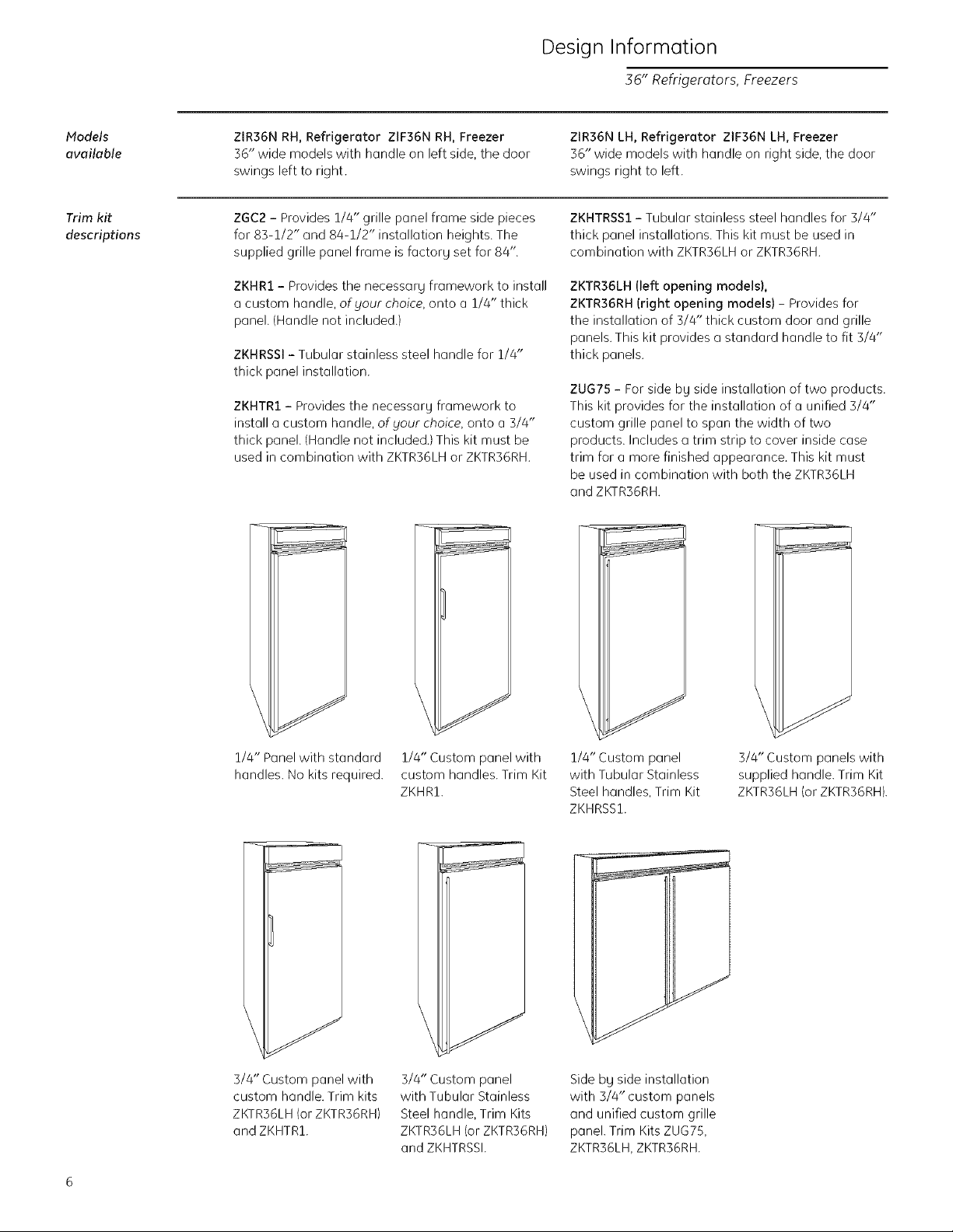
ZIR36N RH, Refrigerator ZIF36N RH, Freezer
36" wide models with handle on left side, the door
swings left to right.
ZGC2 - Provides 1/4" grille panel frame side pieces
for 83-1/2" and 88-1/2" installation heights. The
supplied grille panel frame is factorg set for 84".
ZKHR1 - Provides the necessarg framework to install
u custom handle, of your choice, onto u 1/4" thick
panel. (Handle not included.)
ZKHRSSl - Tubular stainless steel handle for 1/4"
thick panel installation.
ZKHTR1 - Provides the necessar Uframework to
install a custom handle, ofgour choice, onto a 3/4"
thick panel. (Handle not included.) This kit must be
used in combination with ZKTR36LH or ZKTR36RH.
ZIR36N LH, Refrigerator ZIF36N LH, Freezer
36" wide models with handle on right side, the door
swings right to left.
ZKHTRSS1- Tubular stainless steel handles for 3/4"
thick panel installations. This kit must be used in
combination with ZKTR36LHor ZKTR36RH.
ZKTR36LH (left opening models),
ZKTR36RH (right opening models) - Provides for
the installation of 5/4" thick custom door and grille
panels. This kit provides a standard handle to fit 5/4"
thick panels.
ZUG75 - For side b9 side installation of two products.
This kit provides for the installation of u unified 3/4"
custom grille panel to spun the width of two
products. Includes a trim strip to cover inside case
trim for u more finished appearance. This kit must
be used in combination with both the ZKTR36LH
and ZKTR36RH.
1/4" Panel with standard 1/4" Custom panel with
handles. No kits required, custom handles. Trim Kit
ZKHRZ.
3/4" Custom panel with
custom handle. Trim kits
ZKTR36LH (or ZKTR36RH)
and ZKHTR1.
3/4" Custom panel
with Tubular Stainless
Steel handle, Trim Kits
ZKTR36LH (or ZKTR36RH)
and ZKHTRSSI.
1/4" Custom panel
with Tubular Stainless
Steel handles, Trim Kit
ZKHRSS1.
Side by side installation
with 3/4" custom panels
and unified custom grille
panel. Trim Kits ZUG75,
ZKTR36LH, ZKTR36RH.
3/4" Custom panels with
supplied handle. Trim Kit
ZKTR36LH (or ZKTR36RH).
Page 7
Custom Panel Dimensions
36" Refrigerators, Freezers
10-3/4" Max.
10"Min.
_ 24-3/4"_
26-3/4'--
73-1/2"
35" Case f
36" Overall
4,_
_FinishedWidth
2-1/2"
Ii I I'_ LocateGrounded
I I 5" Electrical0utlet I
84-1/2" max I I AreaAbove I
83-1/2"min I I I
Finished I I I
Opening I I
I I Within Solid I
I I LocateFreezerWater I
I I SupplyWithin I
I I S-1/2" ShadedArea 3-1/2"/
J/_ 10" 3-1/2" 10" = \__
84-1/2"Max.
83-1/2"Min.
Wall View
(n0tt0 Scale)
75"FromFloorto
Bottomof
ElectricalArea
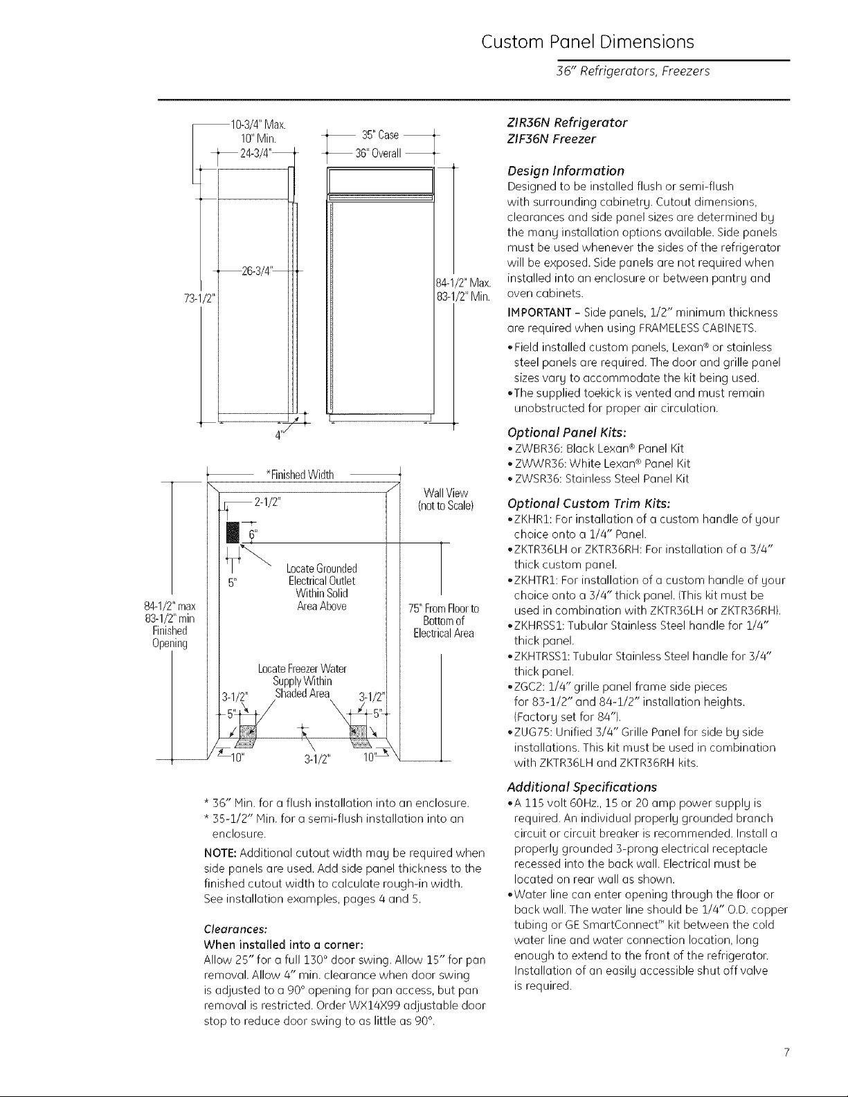
ZIR36N Refrigerator
ZIF36N Freezer
Design Information
Designed to be installed flush or semi-flush
with surrounding cobinetrg. Cutout dimensions,
clearances and side panel sizes are determined bg
the mang installation options available. Side panels
must be used whenever the sides of the refrigerator
will be exposed. Side panels are not required when
installed into an enclosure or between puntr U and
oven cabinets.
IMPORTANT - Side panels, 1/2" minimum thickness
are required when using FRAMELESS CABINETS.
* Field installed custom panels, Lexan ® or stainless
steel panels are required. The door and grille panel
sizes vary to accommodate the kit being used.
,,The supplied toekick is vented and must remain
unobstructed for proper air circulation.
Optional Panel Kits:
* ZWBR36: Black Lexan ® Panel Kit
* ZWWR36: White Lexan ® Panel Kit
* ZWSR36: Stainless Steel Panel Kit
Optional Custom Trim Kits:
*ZKHRI: For installation of a custom handle of gour
choice onto a 1/4" Panel.
*ZKTR36LH or ZKTR36RH: For installation of a 3/4"
thick custom panel.
*ZKHTRI: For installation of a custom handle of your
choice onto a 3/4" thick panel. (This kit must be
used in combination with ZKTR36LH or ZKTR36RH).
*ZKHRSSI: Tubular Stainless Steel handle for 1/4"
thick panel.
*ZKHTRSSI: Tubular Stainless Steel handle for 3/4"
thick panel.
*ZGC2: 1/4" grille panel frame side pieces
for 83-1/2" and 84-1/2" installation heights.
{Factory set for 84'9.
*ZUG75: Unified 3/4" Grille Panel for side by side
installations. This kit must be used in combination
with ZKTR36LH and ZKTR36RH kits.
* 36" Min. for a flush installation into an enclosure.
* 55-1/2" Nin. for e semi-flush installation into an
enclosure.
NOTE: Additional cutout width ma U be required when
side panels are used. Add side panel thickness to the
finished cutout width to calculate rough-in width.
See installation examples, pages 4 and 5.
C]eclrclnces:
When instalJed into a corner:
Allow 25" for a full 130 ° door swing. Allow 15" for pan
removal. Allow 4" rain. clearance when door swing
is adjusted to a 90 ° opening for pan access, but pan
removal is restricted. Order WX14X99 adjustable door
stop to reduce door swing to as little as 90 °.
Additional Specifications
*A 115 volt 60Hz., 15 or 20 amp power supply is
required. An individual properlg grounded branch
circuit or circuit breaker is recommended. Install a
properly grounded 3-prong electrical receptacle
recessed into the back wall. Electrical must be
located on rear wall as shown.
,Water line can enter opening through the floor or
back wall. The water line should be 1/4" O.D.copper
tubing or GE SmartConnect T_'kit between the cold
water line and water connection location, long
enough to extend to the front of the refrigeraton
Installation of an easily accessible shut off valve
is required.
Page 8
Custom Panel Dimensions
36" Refrigerators, Freezers
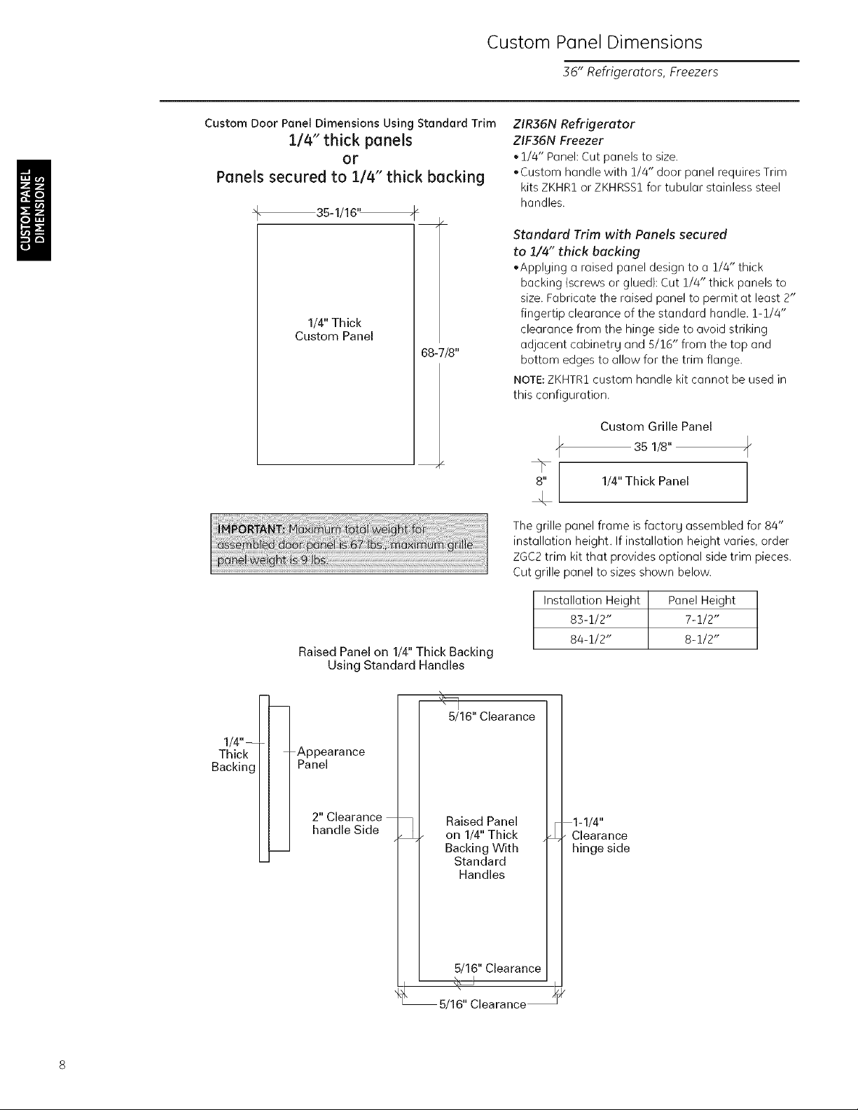
Custom Door Panel Dimensions Using Standard Trim
1/4" thick panels
or
Panels secured to 1/4"thickbacking
35-1/16'_
1/4" Thick
Custom Panel
68-7/8"
ZIR36N Refrigerator
ZIF36N Freezer
,1/4" Panel: Cut panels to size.
,Custom handle with 1/4" door pQnel requires Trim
kits ZKHR1 or ZKHRSS1 for tubular stQinless steel
handles.
Standard Trim with Panels secured
to 1/4" thick backing
,Applging a raised panel design to a 1/4" thick
backing (screws or glued): Cut 1/4" thick panels to
size. Fabricate the raised panel to permit at least 2"
fingertip clearance of the standard handle. 1-1/4"
clearance from the hinge side to (]void striking
adjacent cubinetrg and 5/16" from the top and
bottom edges to allow for the trim flange.
NOTE:ZKHTR1custom handle kit cannot be used in
this configuration.
Custom Grille Panel
35 1/8"
8" 1/4" Thick Panel
The grille panel frame is factory assembled for 84"
installation height. If installation height varies, order
ZGC2 trim kit that provides optional side trim pieces.
Cut grille panel to sizes shown below.
Raised Panel on 1/4" Thick Backing
Using Standard Handles
\
_1 "_._/16" Clearance
BTa'!i_i'nkg[ [ T APnPla ra nce
II I 2 Clearance
L_l handle Side _ I Raised Panel
L t on I/4" Thick
| Backing With
/ 5/16 Clearance
t_ 5/16" Clearance
Installation Height Panel Height
83-1/2" 7-1/2"
84-1/2" 8-1/2"
1-1/4"
Clearance
hinge side
Page 9
Custom Panel Dimensions
36" Refrigerators, Freezers
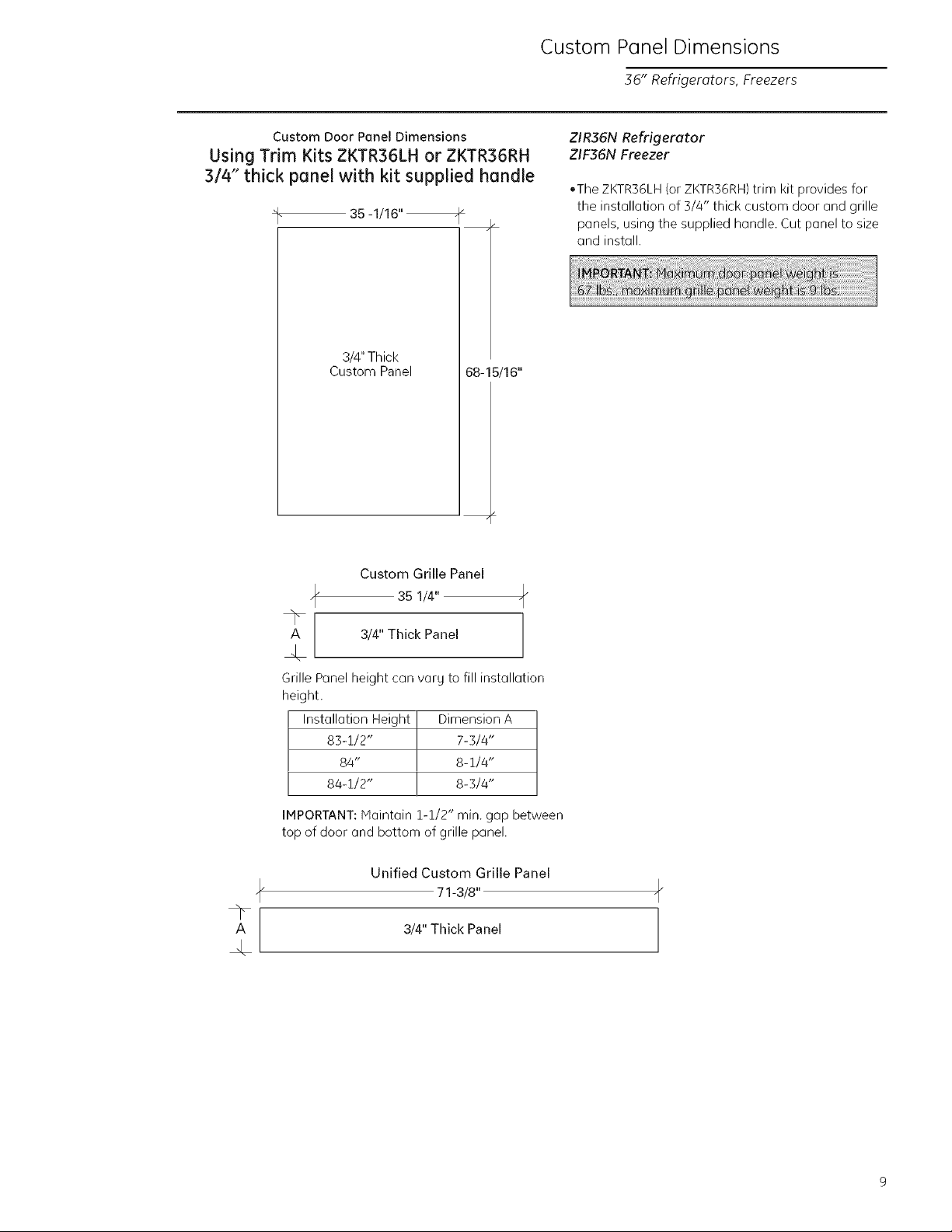
Custom Door Panel Dimensions
Using Trim Kits ZKTR36LH or ZKTR36RH
3/4" thick panel with kit supplied handle
_F 35 -1/16" _
3/4" Thick
Custom Panel
Custom Grille Panel
35 1/4"
mL
68-15/16"
"r
A 3/4" Thick Panel
ZIR36N Refrigerator
ZIF36N Freezer
.The ZKTR36LH (or ZKTR36RH) trim kit provides for
the installation of 3/4" thick custom door and grille
panels, using the supplied handle. Cut panel to size
and install.
Grille Panel height con vary to fill installation
height.
Installation Height
83-1/2"
84"
84-1/2"
IMPORTANT: Maintain 1-1/2" min. gap between
top of door and bottom of grille panel.
UnifiedCustom Grille Panel
A
Dimension A
7-3/4"
8-1/4"
8-3/4"
71-3/8"
3/4" Thick Panel
Page 10
Custom Panel Dimensions
36" Refrigerotors, Freezers
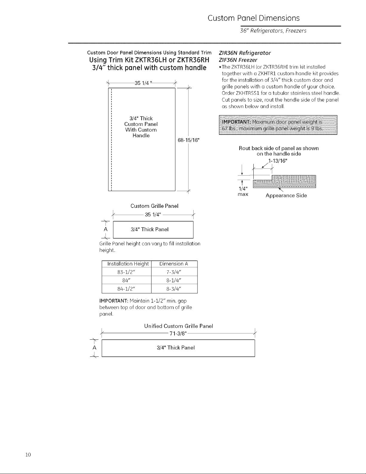
Custom Door Panel Dimensions Using Standard Trim
Using Trim Kit ZKTR36LH or ZKTR36RH
3/4" thick panel with custom handle
4" 35 1/4" ._"
3/4" Thick
Custom Panel
With Custom
Handle
68-15/16"
Custom Grille Panel
35 1/4"
ZIR36N Refrigerator
ZIF36N Freezer
.The ZKTR36LH (or ZKTR36RH) trim kit installed
together with a ZKHTR1 custom hQndle kit provides
for the instollQtion of 3/4" thick custom door and
grille panels with a custom handle of gour choice.
Order ZKHTRSS1 for a tubular stainless steel handle.
Cut panels to size, rout the handle side of the panel
as shown below and install.
Rout back side of panel as shown
on the handle side
1/4" ,%
max Appearance Side
A 3/4" Thick Panel
Grille Panel height con varg to fill instollation
height.
Installation Height Dimension A
83-1/2" 7-3/4"
84" 8-1/4"
84-1/2" 8-3/4"
IMPORTANT: Maintain 1-1/2" min. gap
between top of door and bottom of grille
panel.
Unified Custom Grille Panel
71-3/8"
3/4" Thick Panel
10
Page 11
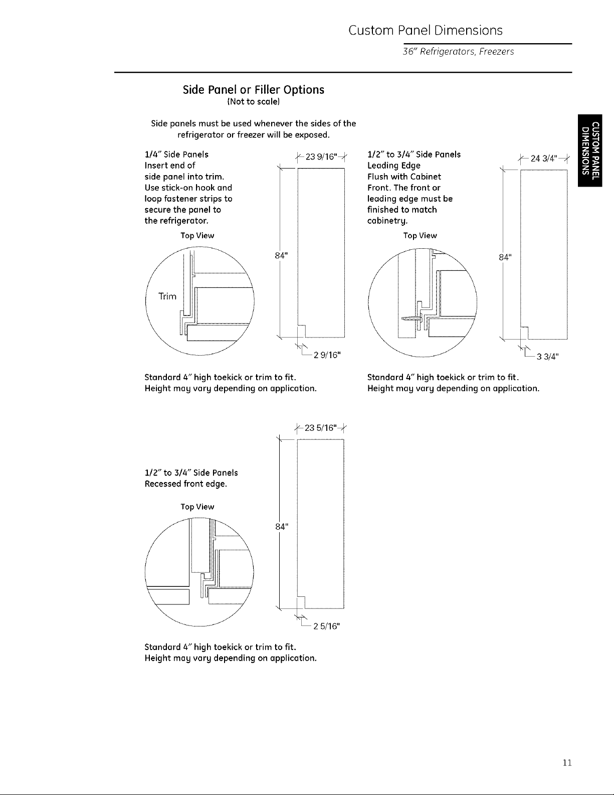
Side Panel or Filler Options
(Not to scale)
Side panels must be used whenever the sides of the
refrigerator or freezer will be exposed.
Custom Panel Dimensions
36" Refrigerators, Freezers
114" Side Panels
Insert end of
side panel into trim.
Use stick-on hook and
loop fastener strips to
secure the panel to
the refrigerator.
Top View
84"
Standard 4" high toekick or trim to fit.
Height may vary depending on application.
23 9/16"1 p
2 9/16"
_23 5/16"=
112" to 314" Side Panels
Leading Edge
Flush with Cabinet
Front. The front or
leading edge must be
finished to match
cabinetry.
Top View
84"
Standard 4" high toekick or trim to fit.
Height mag vary depending on application.
_24 3/4"_
1/2" to 3/4" Side Panels
Recessed front edge.
Top View
84"
Standard 4" high toekick or trim to fit.
Height may vary depending on application.
2 5/16"
11
Page 12
Installation
36" Refrigerators, Freezers
Tools
Required
Materials
Required
Hardware
Supplied
Flooring
Grounding the
Refrigerator
, Tinsnips to cut banding , Bucket
, Stepladder , Level
,1-1/4" open-end , Appliance Hand Truck
wrench , Tubing cutter
, Water shut-off valve
, Water filter WRg7X0214
(optional but recommended)
, Custom panel for door and grille panel
,1/4" Copper water line tubing or GE SmartConnecf"
Tubing Kit
,1/4-1/4 union with nuts
, Anti-Tip Mounting Brackets
For proper installation, the refrigerator or freezer
must be placed on a level surface of hard material
the same height as the rest of the flooring. The floor
should be strong enough to support a fullg loaded
refrigerator or freezer, or approximatel U 1,200 Ibs.
IMPORTANT- (Please read carefullg)
FOR PERSONAL SAFETY, THIS APPLIANCE MUST BE
PROPERLYGROUNDED.
The power cord of these appliances is equipped with
a three-prong {grounding) plug which mates with a
standard three-prong {grounding) wall receptacle to
minimize the possibilitg of electric shock hazard from
this appliance.
Have the wall outlet and circuit checked bg a
qualified electrician to make sure the outlet is
properlg grounded.
Where a standard 2-prong wall outlet is encountered,
it is gour personal responsibilitg and obligation to
have it replaced with a properlg grounded 3-prong
wall outlet.
IMPORTANT:
We recommend two separate l15V, 60Hz. 20 amp.,
properlg grounded electrical outlets for a side bg
side installation of two products. Each electrical
outlet should have a voltage rating that matches
the rating plate.
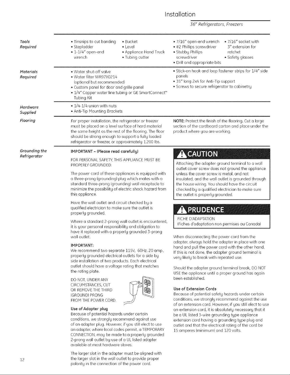
DO NOT, UNDER ANY
CIRCUMSTANCES, CUT
OR REMOVE THE THIRD
{GROUND) PRONG
FROM THE POWER CORD.
Use of Adapter plug
Because of potential hazards under certain
conditions, we stronglg recommend against use
of an adapter plug. However, if gou still elect to use
an adapter, where local codes permit, a TEMPORARY
CONNECTION,mag be made to a properlg grounded
2-prong wall outlet bg use of a UL listed adapter
available at most hardware stores.
,7/16" open-end wrench ,7/16" socket with
, #2 Phillips screwdriver 3" extension for
, Stubbg Phillips ratchet
screwdriver , Safet U glasses
, Drill and appropriate bits
, Stick-on hook and loop fastener strips for 1/4" side
panels
,35" long 2x4 for Anti-Tip support
, Screws to secure refrigerator to cabinetrg
NOTE: Protect the finish of the flooring. Cut a large
section of the cardboard carton and place under the
product where gou are working.
Attaching the adapter ground terminal to a wall
outlet cover screw does not ground the appliance
unless the cover screw is metal, and not
insulated, and the wall outlet is grounded through
the house wiring. You should have the circuit
checked bg a qualified electrician to make sure
the outlet is properlg grounded.
FICHED'ADAPTATION
(Fiches d'adaptation non permises au Canada)
When disconnecting the power cord from the
adapter, alwags hold the adapter in place with one
hand and pull the power cord with the other hand.
If this is not done, the adapter ground terminal is
verg likelg to break with repeated use.
Should the adapter ground terminal break, DO NOT
USE the appliance until a proper ground has again
been established.
Use of Extension Cords
Because of potential safetg hazards under certain
conditions, we stronglg recommend against the use
of an extension cord. However, if gou still elect to use
an extension cord, it is absolutel U necessar U that it
be a UL listed 3-wire grounding tgpe appliance
extension cord having a grounding tgpe plug and
outlet and that the electrical rating of the cord be
15 amperes {minimum) and 120 volts.
12
The larger slot in the adapter must be aligned with
the larger slot in the wall outlet to provide proper
polarit U in the connection of the power cord.
Page 13

Step 1
Remove
Packaging
Refrigerator and freezer is much heavier at the
top than at the bottom - be careful when moving.
When using a hand truck, handle from side only.
Le r6frig_rateur est beaucoup plus Iourd en
haut qu'en bas. II faut &tre prudent Iors des
d_placements. Si un diable est utilis_, il faut
soulever le r_frig_rateur sur le c6t6 seulement.
,, Remove outer carton.
- Carefullg cut banding at the top and bottom.
. Slideout back comer posts (2).
. Slidecarton off top of cabinet.
NOTE:IT ISNOTNECESSARYTOLAYCABINETDOWN
IN ORDERTO REMOVESKID!
. The unit is secured to the skid with 4 slotted tie-
down straps. First remove the 5/16" bolts from the
base channels in the tie-downs, then remove the
7/16" bolts securing the straps to the skid.
. Protect the flooring. Cut a large piece of the
cardboard carton and place under the product.
. Support blocks on the bottom must be removed
before the refrigerator is taken off the skid or
damage will occun Remove support blocks bg
carefullg tilting cabinet to side and sliding out.
Installation
36" Refrigerators, Freezers
7/16"B0k
S
• Lift the refrigerator off the skid with an appliance
dollg. Handle from the sides.
DO NOT ATTEMPT TO ROLL UNIT OFF SKID.
IL NE FAUT PAS ESSAYER DE FAIRE ROULER LE
REFRIGERATEUR POUR UENLEVER DE LAY PALETTE.
13
Page 14

Installation
36" Refrigerators, Freezers
Step 2
Install
Water Line
, A cold water supplg is required for automatic
icemaker operation. The water pressure must be
between 20 and 120 p.s.i.
Route 1/4" OD copper or GESmartConnect TM
tubing between house cold water line and the
water connection location.
Tubing should be long enough to extend to
the front of the refrigerator. Allow enough to
accommodate bend leading into the water valve.
NOTE:The onlg GEapproved plastic tubing is
supplied in the GESmartConnect TM Refrigerator
Tubing kits. Do not use ang other plastic water
supplg line because the line is under pressure at all
times. Other tgpes of plastic mag crack or rupture
with age and cause water damage to gour home.
GE SmartConnect TM Refrigerator Tubing Kits are
available in the following lengths:
2' (.6 m) WXO8XIO002
6' (1.8 m) WXO8XIO006
15'(4.6m}WXO8XIO015
25' (7.6 m} WXO8XlO025
Shut off the main water supplg.
Turn on the nearest faucet long enough to clear the
line of water.
Install a shut-off valve between the icemaker
water valve and cold water pipe in a basement or
cabinet. The shut-off valve should be located where
it will be easilg accessible.
Turn on the main water supplg and flush debris
from the line. Run about a quart of water through
the tubing into a bucket. Shut off water at the
shut-off valve.
Waterline Tubing
Install optional water filter in the water line near the
refrigerator. A water filter is recommended in areas
where water supplg contains sand or particles.
Installation instructions are packed with the filter.
NOTE: Commonwealth of Massachusetts
Plumbing Codes 248CMR shall be adhered to. I
Saddle valves are illegal and use is not permitted in
Massachusetts. Consu t with sour icensed p umberj
14
NOTE:Saddle tgpe shut-off valves are included in
mang water supplg kits, but are not recommended
for this application.
Page 15

Installation
36" Refrigerators Freezers
Step 3
Install
Side Panels
Side panels are not required when the refrigerator
or freezer is installed into an enclosure Skip this
step if gou are installing into an enclosure
Side panels are required whenever the sides of the
refrigerator or freezer will be exposed and when
installed between frameless cabinets See pages
3 and 4
Side panel installation will be determined bg
the design of the side panel gou have previouslg
chosen
Side panels must be installed plumb
Illustration A
I
__)Refrigerator_
Cabinet _
Refrigeratordoor
Cabinet
1/4" Side panels - Insert end of side panel into case
trim. Fasten with stick-on hook and loop strips.
If gou choose to use 1/4"side panels theg should
be inserted into the case trim as illustrated Fasten
the panels to the refrigerator with stick on hook
and loop fastener strips before setting refrigerator
in place See illustration A
1/2" to 3/4" side )anels are normallg set into place
and fastened to adjacent cabinetrg or the back wall
before rolling the refrigerator into the opening See
illustration B
lllustration B
l[ie_rigerator'r_
1/2" to 3/4" Side Panels - Leading edge of side
panel is flush with cabinet front. Fasten to the back
wall using a cleat.
Step 4
Install
Anti-Tip
Brackets
ANTI-TIP PRECAUTIONS
The refrigerator is top-heavg and must be
secured to prevent the possibilitg of tipping
forward.
PRECAUTIONS CONTRE LES BASCULEMENTS
Le r6frig6rateur est beaucoup plus Iourd en
haut et il faut le maintenir en place pour 6viter
la possibilit6 de son basculement vers I'avant.
• Cut a 2" x 4" x 35" block and secure the block to
the mounting brackets provided using #12 or #14
wood screws
• Secure the bracket with wood block to the back
wall so that it is 84" (or gour installation height)
from the finished floon Use #12 or #14 wood
screws See illustration
• Screws must penetrate at least one inch into
vertical wall studs
• Before pushing the refrigerator into the opening
plug the power cord into the receptacle Open the
grille panel and reach into the opening at the back
to grasp the power cord Pull the power cord into
the opening as gou push the refrigerator back
• Gently push refrigerator into the opening with
hands against front corners
Brackets
Required
I
Height
Brackets
NotRequired
Beneatha
Soffit
From
Floor
to
Bottom
ofWood
Block
SideView
2 x 4 Cut _'_
35Length
Installation Mounting
Height Bracket
FromFloor
ScrewsMountedintojJ
VerticalWall Studs
IMPORTANT NOTE: When the refrigerator is installed
under a soffit or if there is not enough height for this
method of security brackets cannot be used Proceed
to step 5 to level the refrigerator and then to step 6 to
secure refrigerator to cabinets The refrigerator must
be secured to prevent tipping
15
Page 16

Installation
36" Refrigerators, Freezers
Step 5
Level
Refrigerator
or Freezer
Step 6
Secure
Refrigerator
or Freezer
to Sides
All models have 4-point leveling. The front is supported
bg leveling legs. the rear is supported bg wheels.
+Adjust rear wheels beneath the product to just barel U
touch the 2x8 block.
.Turn the 7/16" hex nut located above the front
wheels. Turn to raise or lower the refrigerator.
+For front leveling legs. use a 1-1/4" open-end
wrench.
+Adjust carefull U, the refrigerator should be level and
plumb with cabinetr U,and align with toekick height.
The rear leveling wheels and front leveling
legs are limited to a maximum height adjustment
of 1" Ifthe installation requires more than
84 1/2" height the installer should elevate the
refrigerator on a sheet of plgwood or runners
Cabinetrg trim could also be added across the
top of the opening to shorten the opening If gou
attempt to raise the refrigerator more than 1",
gou will damage the front leveling legs and the
rear leveling wheels.
NOTE: Whenever possible, /[7
perform this step for
additional anti-tip securitg.
This step can be used as an
alternate to Step 4, Anti-Tip
bracket installation, whenever
brackets cannot be used.
Hex Nut Adjusts _-_==:_:_=4, I
RearWheels jJ_ll I
Les roues de nivellement arri@re et les pattes
de nivellement avant permettent un r6glage
maximal de 25 mm (1 po). Si I'ouverture pour
le r6frig_rateur a une hauteur sup_rieure
6 2.15 m (84-1/2 po). I'installateur doit _lever
le r6frig&rateur sur une feuille de contre-plaqu_
ou des glissi@res. II est _galement possible
d'ajouter des baguettes de finition des placards
sur le haut de I'ouverture afin de la r6duire.
Lever le r6frig6rateur de plus de 25 mm (1 po)
endommage les pattes de nivellement avant
et les roues de nivellement arri@re.
o _0 ° o
_/ Refrigerator
O00r
Step 7
Connect
Freezer
Water
Supply
16
When using 1/2" to 3/4" side panels, the front flange
of the case trim is attached to the side panel.
+ Open door to access case trim.
+ Drill hole in trim slightlg below the interior opening.
Drive screw through the trim and into the side
panel.
• Locate and bring tubing to the front of the cabinet.
• Turn the water on to flush debris from line. Run
about a quart of water through tubing into a
bucket, then shut-off waten
Copper Tubing:
• Slip a 1/4" nut and ferrule (provided) over both ends
of the copper tubing Insert tube into the union
fitting on the unit and tighten nut to union
• Turn on the water to check for leaks
GE SmartConnect" Tubing:
• Insert the molded end of the tubing into the
refrigerator connection. Tighten the compression
nut until it is just hand tight.
• Tighten one additional turn with a wrench.
Overtightening can cause leaks!
• Turn on the water to check for leaks.
+ Follow the same procedure on the opposite side.
If the product is installed between cabinets with no
side panels or in a custom enclosure, install a spacer
block as shown.
NOTE: Make sure excess tubing length does not
interfere with toekick installation.
Page 17

Installation
36" Refrigerators, Freezers
Step 8
Install I/4"
door panels
Step 9
Check
Power
Step 10
Mount
Top Grille
Panel
If you are using a 3/4" thick custom panel, SKIPTHIS
STEP.See Custom Panel Dimensions pages for panel
sizes with ZKTR36LHor ZKTR36RHtrim kit and other
kits. Refer to trim kit instructions in this booklet.
• Open door to 90° stop. Remove the Phillips head
screws from the aluminum trim door handle.
• Remove handle. Retain all screws and handle.
• Slidecustom panel into the door trim.
• Replace door handle and secure with original
screws.
• Check to make sure power is on bU opening the
door to see if interior lights are on.
If you are using a 3/4" thick custom panel, SKIP THIS
STER See Dimensions and Specifications for grille
panel sizes. Order ZKTR36LH or ZKTR36RH and follow
the installation instructions packed with the kit.
The grille panel frame is factorg assembled for an
84" installation height. If installation height varies,
order ZGC2 trim kit which provides optional side trim
pieces for 83-1/2" and 88-1/2" heights.
Cut 1/4" thick custom panel to fit the frame,
35-1/8" wide, 8" deep {for an 84" installation).
i
Top CaseTrim
Raise T
Installation
Height
To insert custom grille panel into the frame:
, Remove screws (2 on each top corner) and "L"
brackets on each side.
• Slide panel into the frame and reassemble.
• Hount the grille panel bg dropping into slots on the
case trim.
• For shipping purposes, the top case trim is secured
at 84" installation height.
To raise case trim to 84-1/2" or to lower to 83-1/2"
installation height:
, Loosen 2 screws on both sides and raise the top or
lower case trim to meet soffit height or to the top of
adjacent cabinets.
• Tighten all 4 screws.
J
/
IMPORTANT: Maintain 1-1/2" min. gap between top
of doors and bottom of panel frame.
17
Page 18

Installation
36" Refrigerators, Freezers
Step 11
Adjust Door
Alignment
Step 12
Arrange Interior
and Set
Temperature
Controls
Step 13
Start
Icemaker
Check door alignment. The top of the door should
be parallel with the grille panel. If the door appears
to be too high or too low on the handle side,
adjustments can be made by turning the hinge.
• To raise the door, turn adjustable hinge pin
towards the right.
• To lower the dooL turn hinge pin towards the left.
Turn the hinge pin with a 5/16" wrench of-,on some
models, use the 3/16" Allen wrench taped to the
hinge.
• Remove internal packing materials.
• Remove tape from all shelves.
• Set control at "5".
IMPORTANT:Allow 24 hours for temperatures to
stabilize before making adjustments.
• Start the switch to I (on). The green light will come
on and the icemaker will begin operation
automaticallg.
• Be sure nothing interferes with the sweep of the
feeler arm.
• Discard the first few batches of ice cubes.
• To turn the icemaker off, set the switch to O (off).
Allow 45 minutes for the icemaker to resume
operation.
_, oorShouldbeParallel
With Grille Panel
Power Switch
o
3reen Power Light
5/16"Wrench
Step 14
Install
Toekick
18
, A standard toekick is supplied. Install with 2 screws
provided, adjust to desired height and tighten
screws.
IMPORTANT: The vented toekick must remain
unobstructed for proper air circulation and operation.
Page 19

This kit provides optional side trim pieces for the
original grille panel frame to fit 83-1/2" and 84-1/2"
installation heights.
To change grille panel size:
Determine the installation height bU measuring the
enclosure from the floor to the underside of soffit.
When there is no soffit, measure to the top of the
adjacent cabinets.
Adjust refrigerator case trim to desired height.
See Product Installation.
Select the side trim pieces for gour installation
height.
A. Locate original grille panel frame supplied with the
refrigeraton
Remove 8 screws (two on each corner) and "L"
brackets as illustrated.
B. Select correct set of side trim pieces
(2 sets provided).
Secure new side trim pieces to original bottom trim.
_4
Ill ---_- Barrel_ _. .
_:.L Nuts _ u!s,c_a
-_ _,ue ,r,r"_
feces
ZGC2 Trim Kit
Grille Panel Frame Adjustment
E. Mount the assembled panel bg dropping into slots
on the case trim.
/
IMPORTANT: Haintain 1-1/2" min. gap between top of
door and bottom of grille panel
C. Remove barrel nuts from original side trim pieces
(2 each side).
Reinstall the barrel nuts on the new side trim pieces
gou have selected. Discard original side trim.
\
D. Slide custom panel into front slots.
Secure the top trim piece to the frame with "L"
brackets and screws.
19
Page 20

ZKHR1 Trim Kit (For 1/4" Panels)
Support for Custom Handles
Step 1
Remove
handle
Tools and materials required:
#2 Phillips screwdriver
Drill and appropriate bits
Custom door panel
Custom Handle
Safetg glasses
Parts List:
A. Handle side door extrusion (for left hand models)
B. Handle side door extrusion (for right hand models)
This kit provides the necessarg framework to install
a custom handle, of 9our choice, onto a 1/4" thick
custom panel. {Handles not included.) The extrusions
in this kit allow the custom handle to be secured to
the door structure, rather than the door panel.
Select the extrusion for 9our model, discard other
extrusion.
Open door to 90 °. Remove the screws from the full
length aluminum handle.
Retain screws. Discard handle.
Right hand door swing models are illustrated in these
instructions. Follow these instructions for left hand
models.
2O
Page 21

Step 2
Locate
handle
position
ZKHR1 Trim Kit (For 1/4" Panels)
Support for Custom Handles
i.°
3/4" Min.
1-1/2"Max.
Step ._
Assemble
panel
extrusion
and handle
Slide custom panel into the door trim.
Temporaril U secure the new handle extrusion to the
door using at least 2 screws.
The custom handles must be located 3/4" to 1-1/2"
from the edge of the extrusion.
Dec0rat0r_ /
DoorPanel
Handle_ .....
Remove the handle extrusion end custom panel.
Drill 1/16" pilot hole through extrusion.
Drill clearance holes through the panel and
extrusion.
Assemble the door panel, extrusion and custom
handle.
Install screw(s)long enough to pass through the
extrusion, door panel and into the handle.
Slide the assembl U into the door frame until the
new extrusion fits firml U against the steel doon
Reinstall original screws into the door extrusion.
_Extrusi0n
3/a," IVlln.
" Max.
Determine the desired location of the custom
handle and mark centerlines of the screw holes.
Drill 1/16" pilot hole through the panel until it starts
into the aluminum extrusion. This will mark the
matching location for drilling the clearance hole
when assembling the handle, panel and extrusion.
Screw
Decorator
Door _.-/
Panel
21
Page 22

ZKTR36LH/ZKTR36RH Trim Kit
3/4" Custom Ponds
Kit Contents
Right hand door swing models are illustrated in these This kit provides for the installation of 3/4" thick
instructions. Follow these instructions for left hand custom door and grille panels. Handles are included
models, and must replace the supplied handles.
Tools and materials
required:
, #2 Phillips screwdriver
, Drill and appropriate
bits
, Custom door panels
, Putty knife
, Safety glasses
7/16" wrench
Parts List
A.Top trim
B. Handle side trim
C. Hinge side trim
D Bottom trim
E.Support bracket for
custom panel
F.4-3/8" screws for
support brackets
G.Grille support
panel and screws
G
H
P
H. Wood screws #6
1/2" flat head
screws (30)
Step 1
Remove
handles
and trim
NOTE: If you are using a custom handle, see ZKHTR1
installation instructions. For a tubular stainless steel
handle, see ZKHTRSS1 installation instructions.
Open door to 90 °.
Remove the Phillips head screws from the full
length handle, remove and discard handle.
Retain screws.
Open the door fully to stop.
NOTE: Removal of actuator arm allows the door to
be opened wider, giving greater access to hinge
side trim.
Remove the screws from the aluminum trim, top
bottom and hinge side.
Retain screws. Discard original trim and handle.
22
Page 23

ZKTRB6LH/ZKTRB6RH Trim Kit
3/4" Custom Ponds
Step 2
Install
3/4" trim
Step 5
Apply panel
support
brackets
, Attach the new 3/4" trim pieces on the top, hinge
side and bottom using original screws.
, Position support bracket on the back side of the
custom panel, 14-5/16" from the hinge side. Secure
support bracket to panel with screws provided.
I
BackSideCustomPanel
Side
Bottom Edge
Step 4
Install
panels
I ,""
, Place the 3/4" thick panel on the bottom trim with
support bracket tabs inserted into slots. Push the
panel back against the steel door, flush with hinge
side trim.
, Open the door fullg.
, Carefullg drill 4 starter holes using a small drill bit,
through the backside of the trim at the top.
, Install original screws through the trim and into the
panel to secure the panel to the door.
, Drill 6 starter holes through the hinge side and
4 through the bottom trim. Install original screws.
r"
"'% %
23
Page 24

ZKTR36LH/ZKTR36RH Trim Kit
3/4" Custom Ponds
Step 5
Install
handles
Step 6
Adjust
grille
panel height
,, Install new door handle using original screws.
,, For shipping purposes, the top case trim is secured
at the 84" installation height.
. Loosen 2 screws on both sides of the case trim
and raise or lower trim to meet soffit height, from
83-1/2" to 84-1/2".
. Tighten all 4 screws.
IMPORTANT: Haintain 1-1/2" min. gap between top of
door and bottom of grille panel.
iiiiiiiiiiiiiiiiiiiil
TopCaseTrim
RaiseTo1
Installation
Height
Step 7
Secure 3/4"
panel to
grille panel
support
24
. Secure the grille panel support to the bock side of
the 3/4" custom panel with #6 screws.
, Be sure the lip of the support is over the top of the
wood panel.
Panel Support
/
/
/ /
/
/
/
/
/
/
/
Page 25

ZKTR36LH/ZKTR36RH Trim Kit
3/4" Custom Ponds
Step 8
Install
grille panel
,, Install four of the six larger undercut screws so that
the top of the screws ore 1/16" from the surfQce of
the support.
. Attach the assembled panel to the grille opening
by inserting the four protruding screws into the
brQckets on each side.
Back
Grille Panel Support _ "
1/16'_
25
Page 26

ZKHTR1 Trim Kit (For 3/4" Panels)
Support for Custom Handles
Kit Contents
Right hand door swing models are illustrated in these
instructions. Follow these instructions for left hand
models.
Tools and materials required:
, #2 Phillips screwdriver
, Drill and appropriate bits
, Custom door panel
, Custom handle
, Safet U glasses
NOTE: This kit must be used in combination with
ZKTR36LH or ZKTR36RH trim kit for 3/4" panel trim.
Part List:
A. Handle extrusion (for left hand models)
B. Handle extrusion {for right hand models}
This kit provides the necessar U framework to
install a custom handle, of gout choice, onto a 3/4"
thick decorator door panel. (Handles not included.)
The handle extrusion allows the custom handle to be
secured to the door structure, rather than the door
panel.
Select handle extrusion for sour model, discard
other extrusion.
Before
you begin
3/4" custom door panel must be routed to
accommodate these door handle extrusions. Rout
the panel as illustrated, 1/4" deep, and 1-13/16"wide
on the handle side.
Refer to installation instructions for ZKTR36LH or
ZKTR36RH trim kit for 3/4" custom panels:
Follow Step 1 to remove the standard
aluminum trim.
Follow Steps 2 and 3 to attach new 3/4" trim pieces
and to install panel support brackets.
Custom Panel
[_1-13/16"
1/4" Max,_l _ BackSide
I
Handle Side
IMPORTANT: Optimal final appearance depends on
careful routing depth. Do not exceed 1/4" routing depth.
26
Page 27

Step 1
Temporarily
mount door
panel
ZKHTR1 Trim Kit (For 3/4" Panels)
Support for Custom Handles
PIQce the prepared 3/4" custom door pQnel on the
bottom trim with support brqcket tabs inserted into
trim slots.
Push the panel back agQinst the steel door, making
sure the panel is flush with the hinge side trim.
Secure the panel to the trim temporaril U bU
driving 2 screws through the backside of the
trim at the top.
Slide the handle extrusion in between the panel
and steel door.
TemporQril 9 secure the extrusion to the door with
2 screws.
Step 2
Locate
position
of handle
Step
Assemble
panel,
extrusion
and handle
Determine the location of the custom
handles and carefull U mark centerlines
of the screw holes. The hQndles must be
located 3/4" to 1-1/2" from the edge of
the extrusion.
Drill 1/16" pilot hole through the panel until
it starts into the Qluminum extrusion. This
will mQrk the matching location for drilling
a cleQrance hole when assembling the
extrusion, panel and handle.
J
Remove the handle extrusion, the 2 temporarg
screws Qnd custom panel.
Drill 1/16" pilot hole through extrusion.
Drill clearance holes through the panel and
extrusion.
Assemble the panel, extrusion and custom handle.
Install screw(s} long enough to pass through the
extrusion, door panel qnd into the handle.
27
Page 28

Step 4
Mount
assem61ed
panel
I ¢I
Plqce Qssembled pcmel onto the bottom trim with
support bracket tubs inserted into slots.
Push the panel buck against the steel door with
hQndle extrusion flush to handle side of the door.
Open door full Uto stop.
Install original screws qt the top, hinge side and
hqndle side.
ZKHTR1 Trim Kit (For 3/4" Panels)
Support for Custom Handles
• /
4
,t
_z
\
'.. , ", ,,
r
. , ,
28
Page 29

ZKHRSS1 Trim Kit (For 1/4" Panels)
Tubular Stainless Steel Handles
Right hand door swing models are illustrated in these
instructions. Follow these instructions for left hand
models.
NOTE: It is best that 2 people install this kit.
Tools and materials required:
. #2 Phillips screwdriver
Drill and appropriate bits
Custom door panel
Safet U glasses
Center punch
Hasking tape
Hammer
Pencil
1/2" thick 12" x 12" min. piece of plgwood to
protect floor when drilling
For stainless steel panel, wear gloves to protect
against sharp edges.
Parts List:
A. Handle extrusion {for left hand models)
B. Handle extrusion {for right hand models)
C. Door handle
D. 6 Spacer rings (for Stainless Panels ONLY)
(4 required, 2 extra)
E.4 Handle standoffs
F. 6 Screws for mounting handle standoffs
(4 required, 2 extra)
G. 6 Set screws {4 required, 2 extra)
H. 3/32" Allen wrench for set screws
This kit provides for the installation of a Tubular
Stainless Steel handle on 1/4" thick decorator door
panel. The door extrusions allow the handle to be
secured to the door structure, rather than to the
custom panel.
.Select extrusion for 9our model, discard other
extrusion.
Step 1
Remove
handle
Open fresh food door to 90 °. Remove the screws
from the full-length handle.
Retain screws, discard handle.
29
Page 30

ZKHRSS1 Trim Kit (For 1/4" Panels)
Tubular Stainless Steel Handles
Step 2
Match
handle
extrusions
to handle
See Step 2A
for Stainless
Steel panels
• Cut a piece of corrugated to use as a pad to
protect the panel finish. Use 1/2" thick section
of plywood to protect flooring when drilling.
• Place custom panel on the pad, appearance side
down.
• On the back side of the panel-at the handle side,
measure and mark 1/4" below the top edge of the
panel with a pencil.
• Slip panel into new extrusion on the handle side of
the panel.
• Align the extrusion at the pencil mark, 1/4" below
the top of the panel.
• Tape the extrusion to the panel to prevent
movement.
• Center punch and drill 1/8" pilot holes through the
holes in the extrusion and into the panel.
• Turn panel oven On the appearance side, use 9/32"
bit to enlarge clearance hole.
IMPORTANT: Hole locations must be exact to accept
handle standoff and handle assembly.
Custom
Door_ /
Panel
_j_Extrusi0n
I
I
Step 2A If gou are installing handle onto a Stainless Steel
Panel:
Use extreme caution if gou ore drilling through o
stainless steel panel. Stainless steel panels must be
handled gentlg. Do not kneel on the stainless steel
panel. It will leave a permanent dent. Do not remove
protective plastic covering until final installation.
• Place supplied filler panel (corrugated) on floor to
use as a pad.
• On the back side of the panel-at the handle side,
measure and mark 1/4" below the top edge of the
panel.
• Slip panel into the new extrusion, flush against
inner edge, on the handle side.
• Align extrusion to pencil mark as shown in Step 2.
Mark each screw hole location with pencil.
• Tape extrusion to panel to prevent movement.
• Place panel on plgwood section, appearance side
down. Be sure plgwood is clean without nicks and
burrs. Center punch at each screw hole location.
• Drill 1/8" pilot hole. Use 9/32" bit to enlarge
clearance hole.
• Measure and cut a 2" wide strip, top to bottom
off the corrugated panel. This will allow room for
spacer rings between the stainless panel and
extrusion.
30
Page 31

ZKHRSS1 Trim Kit (For 1/4" Panels)
Tubular Stainless Steel Handles
Step 3
Install
standoffs
onto handles
Step 4
Install
handles
and panels
See Step 4A
for stainless
steel panels
. Place a handle standoff onto each attachment post
along the handle. Position the set screw hole on the
standoff to point to the floor.
. Install set screws into the bottom of each standoff,
using the Allen wrench provided. The standoff
should be tight against the handle.
• Slide panel into the door trim. Leave about 4" of the
panel exposed to allow room to install the handle
extrusion.
• Place extrusion onto the back side of the panel,
install mounting screws through the extrusion and
just through the panel.
• Drive screw part wag through the top standoff,
then part wag through the bottom standoff. Install
remaining standoffs part wag.
• Drive all screws until the handle is tight against the
panel.
• Remove tape.
• Slide the assembled panel into the door trim until
the extrusion fits firmlg against the steel door.
Reinstall original screws into the extrusion.
_Screw
Wrench
31
Page 32

Step 4A
Install
handles
and panels
ZKHRSS1 Trim Kit (For 1/4" Panels)
Tubular Stainless Steel Handles
Screw
StainleCs:Ugatet SP!__ _'_ Extrusi0n
Panel ' i
• Crimp top and bottom edges of corrugated
• Slide corrugated into door trim Leave about 1/4"
gap between edge of corrugated and hinge side
trim of the doon
• Slide panel into the door trim. Leave about 4"
of the panel exposed to allow room to install
the handle extrusion.
• Place a spacer ring over each screw hole on the
extrusion. Use tape to hold in place.
NOTE: Panels have a protective plastic covering. Peel
awag just enough to allow panel to slide into trim and to
clear handle mounting screws. The plastic covering will
keep the panel clean during the installation process.
• Place extrusion onto panel. Use a pencil to punch
hole in tape covering spacer rings and align with
screw holes.
• Install mounting screws through the extrusion and
panel.
Be sure to maintain 1/4" gap between corrugated
and hinge side trim.
• Drive screw part wag through the top standoff,
then part wag through the bottom standoff. Install
remaining standoffs part wag.
• Drive screws until the handles are tight against
the panel.
• Slide the assemblg into the door trim until the
extrusion fits firmlg against the steel doon
• Reinstall original screws into the door extrusion.
Raised Panel on 114" Thick Backing:
A raised panel design secured to a 1/4" thick backing
(screwed or glued) can be used with this handle kit. r]-q
• cut the 1/4_' thick panels to size. ,,
Fabricate the raised panel to allow 1-1/4 1/4", Appearance
clearance from the hinge side of the panel to avoid Bacldng FI J
striking
adjucent:- cabinetrg. I I J 5/16
Allow 5/16 clearance at the other edges to allow I LJ Clearance
for the trim flange u handle Side
• Total panel thickness should not exceed 3/4"
• Countertops adjacent to the refrigerator installation
should be mitered 45 °
NOTE: Longer Screws obtained Iocallg will be required
to accommodate panel thickness Use stainless steel
#10 32xl 1/4" truss Phillips head screws
mlcK I I IPanel
Raised Panel on 1/4"Thick Bacldng
II I
5/16"Clearance
Custom Panel
11/4
Clearance
hingeside
5/16" Clearanc_
--5/16"Clearance
32
Page 33

ZKHTRSSl (For 3/4" Panels)
Tubular Stainless Steel Handles
Kit
Contents
Right hand door swing models are illustrated in these
instructions. Follow these instructions for left hand
models.
This kit provides for the installation of a Tubular
Stainless Steel handle on a 3/4" thick decorator door
panel. The door extrusions allow the custom handle
to be secured to the door structure, rather than to
the custom panel.
Select the extrusion for 9our model, discard other
extrusion.
Tools and materials required:
, #2 Phillips screwdriver
, Drill and 1/8", 9/32" bits
, Custom door panel
, Safetg glasses
, Center punch
, Masking tape
, Hammer
_,Pencil
Parts List:
A. Handle extrusion (for left hand models)
B. Handle extrusion (for right hand models)
C. Stainless tubular handle
D. 4 Handle standoffs
E.6 Screws for handle standoffs
(4 required, 2 extra)
F. 6 Set screws (4 required, 2 extra)
G. 3/32" Allen wrench for set screws
This kit must be used in combination with ZKTR36RH
or ZKTR56LH trim kit.
NOTE: It is best that 2 people install this kit.
D E
mmC ,m,,_
Before you
begin:
The 3/4" custom panel must be routed to
accommodate the handle extrusion. Rout the panel
as illustrated, 1/4" deep, and 1-13/16" wide, top to
bottom on the handle side.
Follow the instructions in the ZKTR36RH
(or ZKTR36LH) to install trim onto the door.
Discard the handle supplied with that kit.
Continue the instructions in the ZKTR36RH
(or ZKTR36LH) trim kit to install support brackets
to the bottom of the panel.
Custom Panel
IMPORTANT: Optional final appearance depends on
careful routing depth. Do not exceed 1/4" routing
depth.
33
Page 34

ZKHTRSSl (For 3/4" Panels)
Tubular Stainless Steel Handles
Step 1
Match Handle
Extrusion
to Panel
Step 2
Install
Standoffs
onto Handles
,Cut a piece of corrugated to use as a pad to protect
the panel finish. Additional material ma U be
required to protect flooring when drilling.
Place custom panel on the pad, appearance side
down.
,,Select handle extrusion for uour model, left or right
side extrusion.
Place extrusion against the handle side of the panel.
,Align the extrusion evenlg with the top and bottom
of the panel.
,Tape the extrusion to the panel to prevent
movement.
,Center punch and drill 1/8" pilot holes through the
holes in the extrusion and into the panel.
,,Turn panel oven On the appearance side, use 9/32"
bit to enlarge clearance hole.
• Place a handle standoff on each attachment post
on the handle. Position the screw hole on the
standoff to point to the floon
• Install set screws into the bottom of each standoff,
using the Allen wrench provided. The standoff
should be tight against the handle.
AlignExtrusionEven
With Panel
NOTE: Hole locations must be exact to accept handle
standoff and handle assemblg.
¢
_Screw
Step 3
Install
Mounting
Screws
and Handles
Step 4
Install
Assembled
Panels
• Start mounting screws through the extrusion and
just through the custom panel.
• Stand panel up on the hinge side and hold to
access the appearance side. Place handle against
mounting screws on the appearance side, drive top
screw from the back of the extrusion partially into
the standoff.
• Drive bottom screw partially into the standoff,
and then drive remaining screws partially into
standoffs. Alternate back to the top, driving screws
until the handle is tight against the doon
It is best that 2people perform this step.
• Place assembled panel onto the bottom door trim
with support bracket tabs inserted into slots.
• Push and hold the panel back against the steel
door with door handle extrusion flush to the
handle side of the doon
• Reinstall original screws into the door extrusion.
• Open the door fully to stop.
• Install screws at the top and hinge side.
F
34
Page 35

ZUG75 Trim Kit
Unified 3/4" Custom Grille Panel Kit
Step 1
Install Spacer Pads,
Replace Side Case Trims
This kit provides for the installation of a 3/4" thick
custom grille panel to span the combined width of
a side b 9 side installation. Use this kit in combination
with 3/4" custom panel kits, ZKTR36LH and
ZKTR36RH.
Tools and materials Required:
, #1 and #2 Phillips screwdrivers or sockets
1/4" angled wrench and 1/2" open-ended
wrench
Drill and appropriate bits c
Custom grille panel E
Safetg glasses
Gloves to protect against F
sharp edges
Parts List:
A. Soffit Vent Top
B. Left Side Case Trim
C. Right Side Case Trim
D. Center U-Shape Trim
E.Grille Base Wrap
F. Custom Grille Panel Support
G. Foam Spacer Pads
D
G
CAUTION:Handle parts with care to avoid scratching.
In a side bU side installation, the inside case trim of
both products will be removed and replaced with a
shorter trim.
Lift up to remove the supplied grille panel assembl 9
on both products. Discard both assemblies.
Completion Time: Allow approximatel U 3 hours to
install this kit.
IMPORTANT: 2 People are required to install this kit.
CAUTION: Disconnect power before 9ou begin.
Foam
)Spacer
Pads Remove the Phillips head screws from the inside
AppIg the supplied foam spacer pads to the mating
side of one product as shown.
case trim of each product as shown. Remove and
discard side trim. Retain screws.
Install new side case trim with notches towards the
bottom. Install with original screws.
35
Page 36

ZUG75 Trim Kit
Unified 3/4" Custom Grille Panel Kit
Step 2
Install
Anti-Tip
Brackets
ANTI-TIP PRECAUTIONS
These products are heavg at the top and
must be secured to prevent the possibilitg
of tipping over.
PRECAUTIONS CONTRE LES BASCULEMENTS
Le r_frig_rateur est beaucoup plus Iourd en haut
et il faut le maintenir en place pour _viter
la possibilit_ de son basculement vers I'avant.
Cut a 2"x4" block, 71" long. Secure the 2"x4" to
the 4 mounting brackets provided using #12 or #14
wood screws.
Secure the brackets with wood block to the buck
wall so that it is 84" (or sour installation height)
from the finished floor. Use #12 or #14 wood
screws. See illustration.
Screws must penetrate at least one inch into
vertical wall studs.
Roll Both Products into Opening
. Gentlg push each product into opening with hands
against front corners. Push back into the opening
until it is flush or semi-flush with adjacent cabinets.
Brackets
Required
Height
Brackets
NotRequired
Beneatha
Soffit
From
Floor
to
Bottom
ofWood
Block
m
SideView
2x4Cut_ _-
71" Length ,', ,!
'T÷q
Installation Mounting
Height Bracket
From Floor
ScrewsMountedintoJ
VerticalWall Studs
IMPORTANT NOTE: When the products are installed
under a soffit or if there is not enough height for
this method of securit U, use Step 4 as an alternative.
The refrigerator and freezer must be secured to
prevent tipping.
Step 3
Level Both
Products
36
Both products MUST BE LEVEL AND PLUMB with
each other and adjacent cabinetrg on each side.
Toekick heights should align with cabinetrg.
Adjust carefull U. Both models have 4-point leveling.
The front is supported b9 leveling legs, the rear is
supported b U wheels.
Raise units to the same level, aligning with adjacent
toekick heights.
Adjust rear wheels beneath the product to just
barel9 touch the 2x4 block.
Turn the 7/16" hex nut located above the front
wheels to raise or lower the back of the refrigeraton
To adjust the front leveling legs: Use a 1/4" angled
wrench to turn the top of the leveling leg, or turn
the bottom of the legs with a 1-1/4" wrench.
The rear leveling wheels and front leveling legs
are limited to a maximum height adjustment of
1". If the installation requires more than 84-1/2"
height, the installer should elevate the
refrigerator on a sheet of plgwood or runners.
Cabinetr9 trim could also be added across the
top of the opening to shorten the opening. If gou
attempt to raise the refrigerator more than 1",
gou will damage the front leveling legs and the
rear leveling wheels.
[
HexNut Ad
RearWheels
LevelingLeg
Units must be 1" apart and evenlg aligned at top
and bottom. The inside case trims must align, top
and bottom.
Les roues de nivellement arri_re et les pattes de
nivellement avant permettent un r6glage maximal
de 25 mm 11 po). Si I'ouverture pour le r_frig_rateur
a une hauteur sup6rieure 6 2,15 m (84-1/2 po),
I'instullateur doit _lever le r6frig&-oteur sur une feuille
de contre-plaqu_ ou des glissi&res. II est _galement
possible d'ajouter des baguettes de finition des
placards sur le haut de I'ouverture afin de la r_duire.
Lever le rdrig_rateur de plus de 25 mm (1 po)
endommage les pattes de nivellement avant
et les roues de nivellement arri@re.
Page 37

ZUG75 Trim Kit
Unified 3/4" Custom Grille Panel Kit
Step 4
Secure
Products
To Sides
Step 5
Install Center
Trim Strip
NOTE: This step can be used
as an alternative to Step 2,
Anti-Tip bracket installation,
whenever brackets cannot
be used. Whenever possible,
perform this step for additional
anti-tip securitg.
When using 1/2" to 3/4" thick side panels, the front
flange of the case trim is attached to the side panel.
• Open door to access case trim.
• Drill hole in trim slightlg below the interior opening.
• Drive screw through the trim and into the side
panel.
• Follow the some procedure on the opposite outside
product trim.
• Open doors fullg.
• Starting at the top, press trim strip over inside case
trims of both products.
• Continue pressing trim until gou reach the bottom
of the case trims. The trim will align with the top
and bottom of the case trim.
Stud_Cabinet \
H/Re,r,0erat0r\
OR _
If the product is installed between cabinets with no
side panels or into a custom enclosure, install u
spacer block as shown.
CaseTrim
U-Shape
Trim
Step 6
Remove
Wire Fence
and
Switch Cover
3 Screws
• Remove 5 screws holding the wire fence on both
products. Retain fences and all screws.
j!
i
6rill Base Cover
• Lift off grille base covers. Discard covers.
57
Page 38

Step 7
Install
Grille Base
Cover
Unified Base Cover
• Open doors fully.
• Install the double width grille base cover by
slipping the notched ends over the hinges.
ZUG75 Trim Kit
Unified 3/4" Custom Grille Panel Kit
Place
TrimOver
Hinges
Step 8
Remove
Grille Frame
_%%_%%%%%%%%%%%%%%%%%%%%
°o°Co°o°2222_22_=_! , . , _=9_%%%%%%%%°2o°o°o%° D%%%%%%%%%%%%%%%%%°o%°_Jo%!t
Install
3Screws
• Place wire fence over the grille base cover (textured
side out). Drive original wire fence screws through
the fence, the grille base cover and into the frame.
Screws _!_j
&_€_ _ ° °° °°°° °°°°° °°°°_o22_=O_o%_%%%%_%%%_o_ :_o:_° °° °°°°° °°_o_=o_22_2Z_.... ooooooooooo_C€
• Back out 2 screws on each side of the top
case trim.
• The top piece is secured to the unit with a rubber
dust gasket. Roll the trim upwards to access and
remove end screws as shown. Remove and discard
inside pieces.
• Slide assembly out of the rubber gasket.
jJ
Install
3 Screws
Remove
Screws L_
Remove
Screws
Dust
Gasl<et
38
Page 39

ZUG75 Trim Kit
Unified 3/4" Custom Grille Panel Kit
Step 9
Install
Soffit
Vent Top
SlipDustGasket
IntoTrimOnOneEnd
Separate the top and hinge side trim pieces bg
removing side screws. Discard top piece, retain
screws.
Install one end piece to unified top piece with
2 original screws.
Slip end of rubber dust gasket into end of top
unified piece and slide trim towards the center.
Engage the second piece of gasket and continue
sliding trim until even with opposite ends.
Reinstall end pieces to case trims. Push top piece
up against soffit or to installation height. Tighten
screws on both sides.
Whenever possible, place a level on the top trim.
Adjust side trims until entire grille frame is level.
Slip Second Dust
Gasket Into Trim
/
Reinstall_
Screws /
Step 10
Secure
Custom Panel
ToSupport
• Secure the grille panel support to the back side
of the 3/4" thick custom panel with #6 screws.
Be sure the lip of the support is over the top of
the wood panel.
Panel Support
/
/
/
/
/
/
/
/
/
Back
GrillePanelSupport _. _
• Install four of the six larger undercut screws so that
the top of the screws are 1/16" from the surface of
the support.
• Attach the assembled panel to the grille opening
bg inserting the four protruding screws into the
brackets on each side.
NOTE: Use screws supplied with ZKTR36 Trim Kits.
39
Page 40

Step 11
Adjust
Door
Alignment
ZUG75 Trim Kit
Unified 3/4" Custom Grille Panel Kit
PinSh0
Check door alignment. The top of the door should be
parallel with the grille panel. If the door appears to be
too high or too low on the handle side, adjustments
can be made.
.Use a 5/16" wrench to turn the hinge.
,,To raise the door, turn adjustable hinge pin towards
the right.
,,To lower the door, turn hinge pin towards the left.
5/16" Wrench
_wbg_NO. _49-60055-4 ]
• No• 197D2785P001J
08-07 JR
NOTE: While performing installations described in this book,
safetg glasses or goggles should be worn.
For Honogram ® local service in your area, call
1.800.444.1845.
NOTE: Product improvement isa continuing endeavor
at General Electric. Therefore, materials, appearance
and specifications are subject to change without notice.
GE Consumer & Industrial
Appliances
General Electric Compan U
Louisville, KY 40225
ge.com
 Loading...