

Page 1
Installation
Instructions
ZtFS240
BarRefrigerator
withJcemaker
Zt81240
ZtgS240
Design6uide
With InstallationInstructions
Monogram.°
Page 2
Safety Information
BEFORE YOU BEGmN:
Read these instructions completely and carefully.
for h_ca] im)spector's itse.
IMPORTANT - : 11
codes amid ordim_a_ces.
Note to InstMler - Be sm'e to leave these
im_strl_cti(ms with the (hmslm_er.
Note to Consumer - Keep these im_strm;tio_s with
*olw ()m_er's Mamta] for flttm'e referem_ce.
WARNING - Th,s:,pp,,:,me,m,s
proper]y grom_ded. See be]ow.
AVERT SSEMENT -
Cet appareil doit &ire correcteme_)t mis i'_la terre.
Com_sl*her ci-dessol*s.
If _o[_ recehed a damaged Fresh-Food Ret_igerator
or Bar Re{_igerator with Icemaker, yol_ shol*]d
immediately co]_tact vom" dealer or tm]]der.
Skill Level = h_sta]]atiol_ reqldres basic mecham_ica]
skills. Proper i[]s[a]latio]] is the resp<,isibi]it)of the
im_sta]]er. Prm]loct fhi]m'e (h_e to improper im_sta]]ati<m
is m_otcm'ered m_der the (;E &pp]iam_ce Warramm.
* IJse this app]im_ce ol_]v }br its h_temled [mrpose.
* Immediately repair or replace electrical service
cords that become t_'aved or damaged.
* l I n_p] _g th e _ _ it b eii)re c] ea n_i_ g o r m a]d n_g repai rs.
* Repairs sho_a]d be made by a q_a]ified service
tech _icia n_.
AVERT SSEMENT :
* l] _e _imt _ti]iser cet apparei] q_e po_w ]'_sage po_r
]eq_*e] i] a e_te_c<mstr_*it.
* [1 flint r_parer o_l rempIacer tom
cordo_ d'a]imel_tatio_ 5]ectriq_e e{li]och5 o_
* De_lna_cher ]e bar o_ ]e rSh'ig&'atem" a vi_) mm)t
]e _)etto)age oil tome h)terve])thm.
* I,es r_[:)aratio_s doive_t 0tre ti_ites par m_ tec]micie_
For Monogram local service in your area, call
1.800.444.1845
For Monogram service in Canada, call
1.888o880o3030
For Mmmgram Parts and Accessories, call
1.800.626.2002.
www. mmmgram.com
GROUNDING THE FRESH-FOOD REFRIGERATOR OR BAR REFRIGERATOR
WITH ICEMAKER
IMPORTANT
FOR _ERS )NM, S_FETY. THIS €[ t I3AN _E M[JST BE PROPERIk (;RO[ NDED.
The power cord of this app]im_ce is eq_dpped with a 3-1)ro_g, (grom_di_g) _ohv,>which mates with asta retard 3-[)ro_g,
(grom_di_g) wall receptacle to mi_imize the possibiIit)of electric shock hazard from this app]ia_ce.
Have the wall o_a]et a_d ciro_it checked by a q_taiilied e]ectricim_ to make s_we .....the <aa]et is [)ro[)erh,,grom_ded
\_kherea stamlard=[9-)r(mg, wall o_a]etisel_com_tered, itis_o_wpersom_] respol_sibi]it) an_dob]igatiol_ to have it
)to )er]v grom_ded 3- mmg wall omIet.replaced with a [ [ , , " I ,
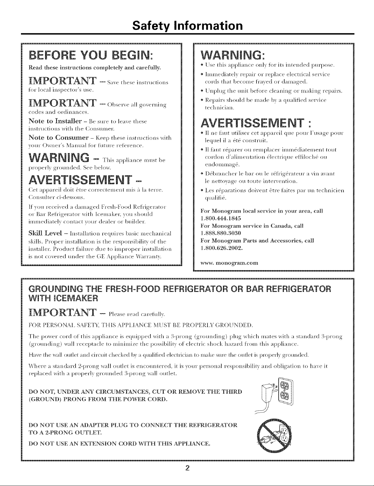
DO NO'I; UNDER ANY CIRCUMSTANCES, CUT OR R_;MOVE THE THIRD _]_]l
(GROUND) PRONG FROM THE POWER CORD.
DO NOT USE AN ADAPTER PLUG TO CONNECT THE REFRIGERATOR
TO A 2oPRONG OUTLE_E
DO NOT USE AN FXTENSION CORD WITH THIS APPLIANCE.
2
Page 3
Installation Instructions
Desig_l Guide {F0r ZIFS2@ and ZIgS240}
The h_stallati0n Space ..................................................................................4
Product Clearances ......................................................................................4
Side-by-Side Installations ..........................................................................4
Desige Guide {F0r ZIFI240 end ZtBI240}
The h-_stallation Space ..................................................................................5
Product Clearances ......................................................................................5
Side-by-Side installations ..........................................................................5
tmpertaat Infertnatiee
Parts Required ................................................................................................3
Carh-_gfor Your Stainless Steel ..................................................................3
Tools, Hardware ............................................................................................3
Staining Wood Drawer Fronts ..................................................................3
Install Water Line ..........................................................................................3
h_staiJatien lestractioes
Step 1, Remove Pad<aging and installation Parts ................................6
Step 2, install Custom 3/4'* Door Panel and Handle
(ZiFI240 and ZiBI240 m0de[s only) ........................................................6, 7
Step 3, Leveling ..............................................................................................7
Step 4, Connect Water Supply {ZIBI240 and ZIBS240 models oely} ___7
Step 5, Connect Power ................................................................................8
Step 6, Slide Product into Cutout ..............................................................8
Step 7, Set Temperature Controls ..............................................................8
ZIFI240 AND ZIBI240 MODELS ONLY
PARTS REQUIRED PARTS SUPPLIED
• Custom handle • Handle side trim
• _ssembled ove_tay panel • Optional black or
• Screws stainless steel toekick
CARING FOR YOUR STAINLESS STEEL
* Be{i)re im_staHatio_ or first I_se, _e stro_gly a(kise that
you po]ish the stah_]ess stee] exterior m_d ]_m_(:[]e With
a commercia]]y avai]ab]e stain]ess stee] c]em_er swb as
Stah_]ess Stee] Magic. >`To preserve amp(I!protect the tirade
finish, we a]so str(mg]y advise that yol_ apply staim_]ess
steel c] em_ er m o1_tb]}.
TOOLS/HARDWARE REQUIRED
* A@_stable wre_ch
* Carl)em/ter s.... ,gh_e (ZIFI24H m_d Z1BI24H mode]s _l_]} r)
* ScrewdriYer (ZIFI940 m_d ZIBI940 models (rely)
= = ,
STAINING WOOD DRAWER FRONTS
The &:a_er fl'oms are mdim_ished cherr_ _ood. Dl*rh_g
IIse, oil }_'(tl_ ha_/ds mav ;_ccllmlllate a_(;[ stai_ the x_(tod.
* The (]h'a_er f_xmts may be sta]_ed a_d sea]ed to match
a(!iace_ t cabi_ etrL
* Apply tile stah_ a_(]! sea]er accordi_g to tile
ma_?ll{i_ctllrer's ]_?stl_lct]o]?s,To avoid m@]easm_t odol;
keep the door (t[:)e_ to ve_ti]ate a_(]! a]](}w the
stai_/sea]er to dr} comp]ete]y be%re _sh_g the prod_ct.
INSTALL WATER LINE (ZlBI240 AND ZlBS240 MODELS ONLY)
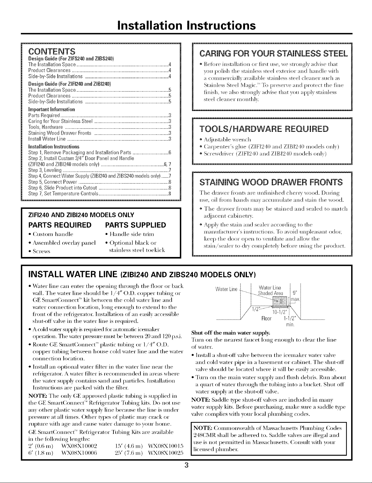
• X,_hter line can enter tile opening through tile floor or back
wall. Tile water line should be l/4" O.D. copper tubing or
GE SmartCom_ect _'_kit between tile cold water line and
water connection location, long enough to extend to tile
ti'ont _ff the reti_igeratm: Installation of an easily accessible
shut-off wflve in the water line is required.
• A cold _mr stq/l/ly _srequired tor autoinafic icemaker
operation. The _v:lteI" lX'essum inttst be between 20 and 120 p.sJ.
• Route GE SmartConnect _'_plastic robing or 1/4" O.D.
coi)per robing between house cold water line and tile water
connection location.
• Install an optional water filter in tile water line near tile
refrigerator. A water filter is recommended in areas where
tile wamr suI)ply contains sand and particles. Installation
Instructions are packed with tile filte_:
NOTE: The only GE aplx'oved plastic robing is sui)plied in
the GE SmartCom_ect _"Refl-igerator Tubing kits. Do not use
any other plastic water SUl)ply line because tile line is under
pressm'e at all times. Other t,ipes of plastic may crack or
rui)mre with age and cause water damage to wmr home.
GE SmartCom_ec( _'Refiigerator Tubing Fdts are available
in the following lengths:
2' (0.6m) X._3X08X10002 15' (4.6m) X.%X08X10015
6' (1.8 m) WX08X10006 25' (7.6 m) WX08X10025
Shut off the main water supply.
Tm'n on tile nearest fimcet long enough to clear tile line
of water.
• Install a shut-off \_flve between tile icelnaker water valve
and cold water pipe in a basement or cabinet. The shut-off
wflve should be located where it will be easily accessible.
• Tm'n on tile main water SUl)ply and flush debris. Rm_ about
a quart of water through tile robing into a bucket. Shut off
water sui)ply at tile sh ut-_)ff valve.
NOTE: Saddle type shut-off \;fives are included in manv
water sui)ply kits. Before i)urchasing, Iuake sure a saddle type
\:five complies with yore" local i)lumbing codes.
NOTE: Commonwealth ot Massachusetts Plumbing Codes
248CMR shall be adhered to. Saddle vah'es are illegal and
use is not pemfitted in Massachusetts. Consult with wmr
licensed I)lumbe_:
Water Line
rain,
3
Page 4

Design Guide
For models ZlFS240 and ZlBS240 with Stainless Steel Doors and Handles
THE INSTALLATION SPACE
I Z4_.., _!aieEr:line location
'_' I_ _ iorZlB1240or
i z,Bs240,.ode,on,y
Mir__'_',i 23-3/4 '_
NOTE:
Handleand
handlestandoff
depthis 2-1/4"
The cutout depth should be 24"
swim_g amid access to die im]]-om racks _]_em_ im_sta]]ed
im_stm_dard 24" deep cabim_ets.
• Th e Fresh-Food Relhi gerator or Bar Relhf ge_u tot wi th
]cemaker cam_ be im_sta]]ed f_'eestam_dim_g.
• }if im_stal]h_ g a stai m_]ess steel m ode] betweem_ t]'am eless
cab] m_ets, a ] / 2" wide []]]er stri p or s] de pa m_e]m ay be
m_eeded cm the ]]h_ge side. The filler strip wi]] act as
a spacer betwee_ the case amid a(!jacem_t cabh_et door
swi m_g. The width of the opel_i m_gmust i_ c]ude th e
filler pa_e]s.
Note: The stai_]ess steel door sh<m]d be fl _mh _ith
t]_e sm'rom_di_g cabi_ets.
Additional Specifications
& 12(I volt 60Hz., 15 or 20 amp power supp])' is
required. _n i_dh'idua] proper]) groin/tied bra_ch
circuit or c[rc_dt breaker is recomme_ded. }in,stall a
proper]) _gr°m_ded 3-l/tong, electrical receptacle
recessed i_to die back wail as s]]owm Electrical must
be located on rear wail as shown, NOTE: (;FCI (groined
fhu]t c[rodt i_termpter) is m_t
26" _ 34-1/2"
including A
Handle
PRODUCT CLEARANCES
The Fresh-Food P,e[Hgerator or Bar Re[Hgerator wit])
]cemaker is titctorv set [or a ] ] 0 ° door swh_g.
When instammedin a corner:
Allow 14" minimum c]eanmce o]) the binge side
fi_r a fuji ] ] 0 ° door swh_g.
* Allow 4" mira c]eara_ce o]_ the hinge side ti)r the
90 ° door swi_g a_d to allow racks to slide out.
NOTE: C]eamn_ces are based oil the recommel_ded
2-1 / 4" h a _ d]e sta _ digit dept]_.
14" Minimum
Swing
110° Door [
t ', \
110_'.
NOTE: Right hm_d mode]s i]h_st_:/ted. A]]ow d_e same
c]ea_mces o_ the opposite side for left ha_d models.
* Test the door swi_g. Careflfl]y ope_ an_d dose the
door. The door sho_fld _]ot mb or catch o_ a(!jace_t
cabiuetrL Not]f\ the i_sta]]er if the door makes
cow,tact with cabi_ etrL
Choose the mocation:
These products may be dosed ]_)on the top a_)d
three sides as ]o_g as the f}'o_ t is m_obstr_cted fin"
air circ_flatio_ an_d proper access to the door.
* Do _ot h_sta]] these prod/_cts where the temperature
wi]] go below 55°F (13°C) or above 90°F (32°C).
* These products are m_t designed to be stacked one
over the other.
Wail
Swing
90° Door 21-5/8"
[
_ 23-5/8"
kk,k
90°
-._ [
4" Minimum to Wail
SIDE-BY-SIDE INSTALLATIONS
For a complete re{reshment center, i_]sta]] a Fresh-Food ]-_.eirigerator
beside a l_)oub]e Dl_lwer P.e[rigel:mn', Beverage Center or _'Vi_e
Chi]]er/\_,i_e P,eserve. Or, i_sta]] a Re[rigerator with lcemaker beside
a \'_i_e Chi]]er/_,Vi_e Reserve. 34-1/2"-35"
* A side-by-side i _sta]]atio_ req uires at least a 47-1/2" _rHde openi _g [
No trim ]<its required.
* Prod_lcts m_mt operate from separate, proper]), grom_ded receptacles.
4
0ut[et
"2
1-1/2"
47-1/2" Min k
Page 5

Design Guide
For models ZlFI240 and ZlBI240 with Custom Door Panels and Handles
THE INSTALLATION SPACE
\ i ....
............... * _ _1 Water line location
Lg4-1/z"-3b" _ Max, " BI
:_4q/Z-:_ J_ Ma:_ ,1_ _ ] f0rZlBI2400r
// 1-I/2"\ _ ZIBS240 model only
NOTE:
Handleis
notsupplied?
_Customhandleclearancesmayvary,
depending on the standoff of the custom handle.
The cutout depth should be 24"
swim_g a_](;l access to tl_e [:)ull-ol_t racks when_ im_stalled
ill sta[]dard 24" deep cabi[]ets.
* The Fresh-Food Regrigerator or Bar Re[Hgerator with
]cemaker cam_ be h_stalled greestam_dh_g.
* 1_ a stm_dard 24" o}:)e_im_g, the re{Hgerator door w]]]
prom_de ]i-3/4" Iti)rward of d_e a(!j:_cen_t cabim_ets.
Additional Specifications
e A 12(} volt 60Hz., 15 or 2(} amp power slq:)p]y is
require(L A]] im]divi(]l_a] properly groin]tied bra_]ch
circuit or ch'ofit breaker is recommen_de(L h_stal] a
properly grom_ded 3-pr(mg electrical receptacle
recessed im_to the back wail as show]]. Electrical must
be located o]_ rear wail as s]]ow]_. NOTE: (;FCI (groined
g_ult ch'clfit h_termpter) is m_ot recomme]_ded.
Black or Stainless Steel Toekick Options
e These prodl_cts are shipped _dt]] a stainless steel toekick
a_d a ]black toeldck For sl]ipph_g pro'poses, o_e of die
u)eldcks will be secm'ed to tl]e back o{ d_e m_it, a_d the
secxmd will be h_smiled o_ the m/it Keep die mmsed
toeldck ;rod a_y mmsed parts for hm_re _se.
_ 24" NOTE:
24-7/8"
_23-3/4" I
PRODUCT CLEARANCES
Tile Fresh-Food Refrigerau)r or Bar Refrigerator with
lcemaker is fi_cto_a set for a I I0 ° door s_rH ]_g,
When installed in a corner:
* Allow 16" m ihim m_ c]eara _ ce ol_ th e hm_e side
for a fl_ll 110 ° door swi_g.
* Allow 4-1/2" mira c]eara_ce on tile hi_]ge side for
die 90 ° door swi_g a_d to allow racks to slide o_t.
NOTE: Cmtom ha]Idle clea_;mces may vat}, depe_dh_g
(m tl_e st;mdof_ (ff tl_e custom ha_dle.
16" Minimum to Wall
0oDoorswng
Swing
110° Door
L.
"LL
90°
110° .. ',,',,
NOTE: Right ha_d models illust_te(L A]lo_ die same
clea_mces o_ d_e opposite side fi)r left ha_d models.
* Tes_ d_e door swi_g. (l;aref_]]y ope_ m_d close die
doo_: Tile door s]]o_]d _o_ r_b or ca_ch o_ a(!iace_
cabi_etrv. Notif\' tile i_sta]]er if tile door makes
c(mtact wit]] cabi_]etrL NOTE: Whe_ h_sta]]i_g
ciis[om pro)el a_)d liar)die, ilse above cleal:mces as a
ge_eral g_fide but a(!iust accordh_g to d_e h_smllado]_.
4-1/2" Minimum to Wail
Choose the location:
* These I:)rod_c[s ma_ he closed h) o_) d)e lop m)d
d_ree sides as lo_g as die fl'oi_t is m_obsn'wted fl)r
air circ_lati(m m_d proper access to tl_e door.
* Do _ot h_sta]] these prod_cts where the temperatm'e
w]]] go below 55°F (13°(:) or above 90°F (32°C).
* These products are m)t designed to be stacked (me
over the other.
[[ 234/8"
SIDE-BY-SIDE INSTALLATIONS
For a complete retreshment center, install a Fresh-Food Refrigerator
beside a Double Drawer Refrigerator; Bexerage Center or _4ine
Chiller/_4ine Reserve. Or, install a Refl'igerator with ]cemaker beside
a _,_ine Chiller/_4 ine Reser_ e. 34-1/2"-35"
• A side-by-side installation requires at least a 47-1/2" wide oi)ening., [
No trim kits required.
• Products must operate ti'om separate, properl) grounded receptacles.
5
15"_ - 7 -' T2_' [_ I
........... lq/2" \ [
47-1/2" Mitt ;k_
Page 6

Installation Instructions
ISTEP 11 REMOVE PACKAGING
AND INSTALLATION PARTS
• Remove corner blocks and t0am drawer stops.
• Remove all packing material, tape and protective
i)lastic coverings.
• Remove the toekick attached to the back of the unit.
• Remove the custom panel attached to the fl'ont of
the unit.
CAUTION: Sm.ll l,,,ke
hazard for children, Remoxe and discard any parts
not used.
ATTENTION :,.e.l e"t pe.,e.t
_trangler les enfimts. 11tautjeter toutes les pi_ces qui
ne sont pas utilis_es.
ISTEP21INSTALL CUSTOM 3/4"
DOOR PANEL AND HANDLE
(ZlFI240 and ZlBI240 models only)
ISTEP21
INSTALL CUSTOM 314" DOOR
PANEL AND HANDLE (CONT.)
(ZlFI240 and ZlBI240 models only)
Assemble overlay panels
with glue and screws.
• Center spacer panel on the
backer panel, left to fight and
top to bottom. Secure the
panels _ifl_ glue.
• Center the spacer/backer
panel on the overlay panel.
Secure with glue and screws. Counmrsink all screws
into the backer panel.
Custom Panel Hinge Routing Dimensions
Use a 3/4" router bit to cut a notch into the back side
of the assembled panel 3/8" toward the fl'ont of the
overlay panel, 3/4" deep and 7/8" wide.
NOTE:Righthand models
illustrated. Cut notches ,\
onthe opposite side for
left hand door swing. '\',
/ _]i' "i
3/4" Overlay Panel Dimensions
Model ZIF]240 and ZIB]240
require a field-installed overlay
door panel. Panel
• The overlay panel must be Door J
secured to a 1/4" thick backer
panel that slides into the trim.
A .10" thick spacer panel must
be placed between the o_erlav 1/4" ,,
and backer panel, gacker_ _10 Inch
• A custom handle ot your choice,
SUl)plied by your cabinetmaker; must be installed
on this overlay panel. Countersink all scrm_:s into
the backer panel. Scre_:s cannot protrude fl'om the
backer panel.
IMPORTANT NOTE: Maxim um total weight fi_r
custom door panel is 25 pounds.
1/4" F,acker 23-3/16" 29-9/16"
a.la" Sp;I(:( l 22-1/2" 29-1/16"
3/4" ()_e_la} 23-5/8" 3a"
Panel Spacer
Overlay
3/8"
Install custom door panel and handle:
• (-)pen door to 90°.
• Remove 5 screws holding trim; lift olI trim.
Retain screws.
Back side 0I
custom panel
NOTE:Right hand models
illustrated. Follow the
same instructions on the
opposite side for left
hand models.
'")i
1
6
Page 7

Installation Instructions
]STEP 21
INSTALL CUSTOM 3/4" DOOR
PANEL AND HANDLE (CONT.)
(ZlFI240 and ZlBI240 models only)
Install custom door panel and handle (cont.):
• A custom handle of your choice, supplied by your
cabinetmake:; must i_e installed onto the overlay
panel befi>re tile panels are slid into the trim.
Countersink all screws into the backer panel,
Screws cannot protrude fl'om the backer panel.
Screws Must
BeCountersunk
Into Panel
Door Panels
• Slide oxerlay panel into the door trim.
) Turn Right to Lower
Turn Left to Raise
]STEP 4] CONNECT WATER SUPPLY
(ZIBI240 and ZIBS240 models only)
• Reinstall the side trim using the trim screws
:'eIl/OX ed earlier.
7
.-
• Place the b:ushed decoratixe cover oxer the side trim
to hide the screw heads, Ensure side trim is aligned
top to bottom and front to back, Snap into place,
NOTE:
Forshipping
purposes,the
brusheddecorative
coverwill be
securedto the
frontof the unit.
1/4" T___ fr_____ 1/4,,
u__ :_.!j [ J l'x/Compression
SmartConnectTM Tubing / _ Refrigerator
Connection
• Ix>cate and bring the water line tubing to the rear
of the cabinet.
• Turn the water on to flush debris from the line.
Run about a quart of water through the tubing
into a bucket, then shut off' the water.
Copper Tubing:
• Slip a 1/4" nut and tell ule over both ends of the
copper tubing. Insert the tube into the refl'igerator
connection on the unit and tighten the nut.
• Turn on the water to check tot leaks.
GE SmartConnect TM Tubing:
• Insert tile molded end of the tubing into the
refl'igerator connection. Tighten the compression
nut until it isjust hand tight.
• Tighten one additional turn with a wrench.
Overtightening can cause leaks!
• Turn on the water to check tot leaks.
NOTE: Coil excess tubing length behind the unit.
Page 8

mnstaJiation mnstructions
[STEPSlCONNECTPOWER
• Com_ect F,Ov,'er cord _hw_ toa properly _grc'm_ded
receptacle.
• Check to make sm'e power is o_ by o_e_im_g_the door
tosee ifim_teriorlighttm'm_som
• Bar P,elhigerator _{rith lcemaker - The i_terior thn]
rm_s all the time except (b_rin_g (;[efrost _;cle whe]_
the door is opem
• Fresh-Food Reltrigerator-The im_terior tim rims
all the time except whe_ the door is opera
See the Owner's Manmal fl_r fla'ther e×phmatiom_ of the fire.
[STEP 6] SLIDE PRODUCT iNTO
THE CUTOUT
CAUTION: D,, ,<,
pan, el whh yore" lmees. Do _ot p_*sh or l],h the m_]t by
the door ha_d]e. Damage may occm'!
ATTENTION
pa_ea_ de la porte avec yes gen_o_x. Ne po_ssez
jamais votre appare]] o_ _e ]e so_,]evezjamais par ]a
poig_e_e de porte. Vo_s pouvez l'endommager.
* ()pe_ the door a_d ge_t]y p_*sh the m_]t back i_to
the ope_i_g with yo_,r ha_ds agai_st the sides.
Be care{ill _ot to e_mmgle power corck
* h_ a sta_dard 24" ope_]_g, the }_'o_t fi_ce of the
stai_]ess steel door wi]] be fb*sh with a@ace_t
cab]_et_w. A custom pane] door may protrude
1-3/4" beyo_d the s_*rrom_di_g cab]_ets.
* (beck aga]_ to be s_*re the m_h is ]eve].
* If the m_it is i_sta]]ed m_der a com_tertop, a@_st
the leve]h_g legs m_t]] the m_h is resti_g []rm]y
agai_st the m_derside of the com_tertop.
* If a]ig_ m e_ t w]th a@a ce]_ t cab] _ etrv is a _ ]ss_e,
_se a shim to secrete the m_it agai_st the m_derside
[STEP 71 SET TEMPERATURE
* The temperature controls are preseL Reibr to
the ()_]]er's Mamml fl)r more ]m]}brmathm. A_()*_ r
]2-24 horns fin" the temperatm'e to stabilize.
NOTE: The Fresh-Food Rei_igemtor or Bar Re}_'igerator
with [cemaker operate vet> ql*ietly. \_l* mav m_ot m_otice
the m_it nmm_h_g, and _hem_ first h_stalled, the I_ims and
motor may _ot come o_ immediately - this is Ho11"_/1.
If the display is lit a_d the light is workh_g, the m_h is
Pub.No. 31-51544-3 ]
Part No. 197D5893POO2J
04-05JR
Printedil_Slovenia
l
NOTE:While performing installations described inthis book,
safer€ glasses or goggles should be worn,
Ynr Mo_m_'mm¢' /o('a[,_(_r_,k'eb_3o_r atz_a,ca#
l. 1500.444. t_4 .
NOTE: PFO(]LICI ill]})l'OV{ Ill( 111 iS ;t (7OIllillt/Lll_ ( IId(HV(}I"
Monogram?
GEConsumer & Industrial
Appliances
General Electric Company
Louisville, KY40225
© 2005 General Electric Company
 Loading...