

Page 1
Installation
Instructions
36" Built-in All-Refrigerators
and All-Freezers
31-49062-2
224D2601 PO02
01-15 GE
monogram,com
Page 2
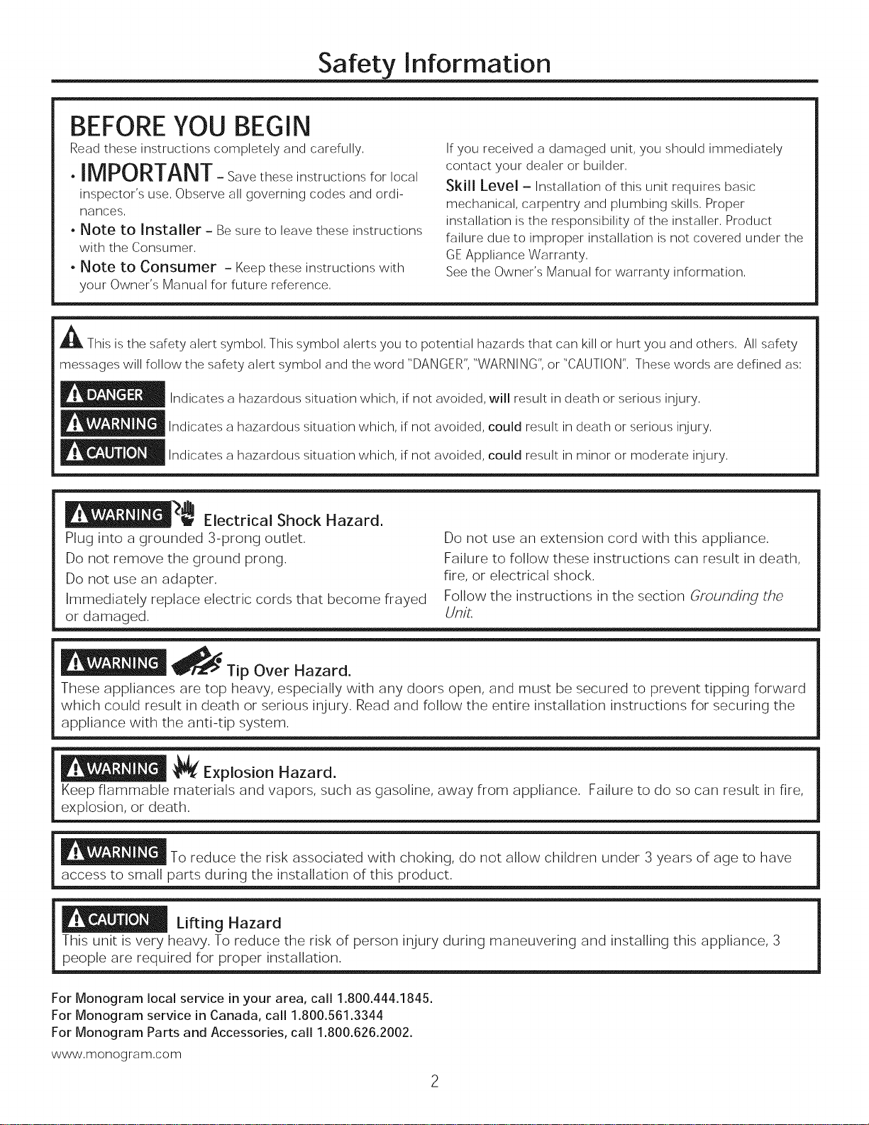
Safety information
BEFOREYOU BEGIN
Read these instructions completely and carefully,
.IMPORTANT- Savetheseinstructionsforlocal
inspector's use, Observe all governing codes and ordi-
nances,
. Note to Installer - Be sure to leave these instructions
with the Consumer,
• Note to Consumer - Keep these instructions with
your Owner's Manual for future reference,
A This is the safety alert symbol, This symbol alerts you to potential hazards that can kill or hurt you and others, All safety
messages will follow the safety alert symbol and the word "DANGER", "WARNING", or "CAUTION", These words are defined as;
Indicates a hazardous situation which, if not avoided, will result in death or serious injury,
Indicates a hazardous situation which, if not avoided, could result in death or serious injury,
_ Indicates a hazardous situation which, if not avoided, could result in minor or moderate injury,
If you received a damaged unit, you should immediately
contact your dealer or builder,
Skill Level - Installation of this unit requires basic
mechanical, carpentry and plumbing skills, Proper
installation is the responsibility of the installer, Product
failure due to improper installation is not covered under the
GE Appliance Warranty,
See the Owner's Manual for warranty information,
__ Electrical Shock Hazard.
Plug into a grounded 3-prong outlet.
Do not remove the ground prong.
Do not use an adapter.
Immediately replace electric cords that become frayed
or damaged.
!_ Tip Over Hazard.
These appliances are top heavy, especially with any doors open, and must be secured to prevent tipping forward
which could result in death or serious injury. Read and follow the entire installation instructions for securing the
appliance with the anti-tip system.
_{ Explosion Hazard.
Keep flammable materials and vapors, such as gasoline, away from appliance. Failure to do so can result in fire,
explosion, or death.
To reduce the risk associated with choking, do not allow children under 3 years of age to have
access to small parts during the installation of this product.
Lifting Hazard
This unit is very heavy. To reduce the risk of person injury during maneuvering and installing this appliance, 3
people are required for proper installation.
Do not use an extension cord with this appliance.
Failure to follow these instructions can result in death,
fire, or electrical shock.
Follow the instructions in the section Grounding the
Unit.
For Monogram local service in your area, call 1.800.444.1845.
For Monogram service in Canada, call 1.800.561.3344
For Monogram Parts and Accessories, call 1.800.626.2002.
www.monogram.com
Page 3
CONSIGNES DE SECURITE
ACe symbole represente une alerte de s6curite, Ce symbole vous avise de dangers possibles pouvant causer la mort, des
blessures ou autres, Tousles messages de s6curite seront prec6d6s du symbole d'alerte de s6curite ainsi que des mots <<
DANGER >>,<<AVERTISSEMENT >>ou <<MISE EN GARDE >>,Ces messages sont les suivants :
Signale une situation qui presente un danger imminent et qui, si elle n'est pas evitee, entrainera des bles
sures graves, voire la mort,
Signale une situation qui presente un danger imminent et qui, si elle n'est pas evitee, peut entrainer des
blessures graves, voire la mort,,
_ ignale une situation qui presente un danger imminent et qui, si elle n'est pas evitee, peut entrainer des
blessures mineures ou graves,
Risque de choc electrique.
Branchez I'appareil dans une prise triple avec terre.
Ne retirez pas la broche de terre.
N'utilisez pas d'adaptateur.
Le non-respect de ces instructions peut entrainer des ris-
ques d'incendies, des chocs electriques ou la mort.
N'utilisez pas de rallonge avec cet appareil.
Le non-respect de ces instructions peut entrainer des ris-
ques d'incendies, des chocs electriques ou la mort.
Suivez les instructions de la section Mise a/a term du
refrigerateur,
Remplacer immediatement tout cordon electrique effilo-
che ou endommage.
_/_ Risque de basculement
Ces r6frigerateurs presentent une partie superieure Iourde, en particulier avec une porte ouverte; ils doivent doric
6tre fixes pour prevenir le basculement vers I'avant et le risque concomitant de blessure grave ou fatale. Lisez et
suivez les instructions d'installation completes pour I'installation du systeme anti-basculement
_!_1[-€Risque d'explosion.
Conservez les materiaux et vapeurs inflammables tels que I'essence a I%cart de votre refrigerateur. Le non-
respect de cette instruction peut entrainer un risque d'incendie, d'explosion ou de deces.
Pour reduire le risque d%touffement pendant I'installation de ce produit, ne pas laisser les
petites pieces a la portee des enfants 896s de moins de 3 arts.
Risque associe a la manutention d'une charge Iourde
Ce refrig6rateur est tres Iourd. Pour reduire le risque de blessure lots de la manutention de ce refrigGrateur, trois
(3) personnes sont necessaires pour proceder a I'installation appropriee du modele 36 pouces, quatre (4) pour
I'installation des modeles 42 ou 48 pouces.
Page 4
Contents
Safety
Planning Guide
The Installation Space
Dimensions and Clearances
Customization Basics
3/4" Overlay Panel Dimensions - Flush
1/4" Framed Panel Dimensions - Standard
3/4" Overlay Panel Dimensions - Standard
Side Panels
ZUG2 and ZUGF2 Grille Panel Dimensions
130 ° Door Swing
90 ° Door Swing
Installation Instructions
Tools, Hardware, Materials
Grounding the Unit
Parts Identification
Step 1, Remove Packaging
Step 2, Install Water Line
2,3
5-7
Step 3, Install Side Panels
Step 4, Install Case Trim
5
Step 5, Anti-Tip Procedures
Step 6, Level Unit
8
Step 7, Secure Unit to Cabinetry
9
Step 8, Secure Unit to Wall
10
Step 9, Adjust Door Swing
10
Step 10, Remove Door Trim
11
Step 11, Layout Decorative Door Panels
11
Step 12, Attach Brackets to Panels
Step 13, Hang Decorative Door Panels
12
Step 14, Layout Decorative Grille Panel
13
Step 15, Install Grille Panel
Step 16, Adjust Decorative Panels
14
Step 17 Replace Trim
14
Step 18, Connect Water Supply
15
Step 19, Start Icemaker
16
Step 20, Install Toekick
16
16
17
18-19
2O
2O
21
23
22
23
24
25
26
26
27
28
29
29
29
Page 5
Design Guide
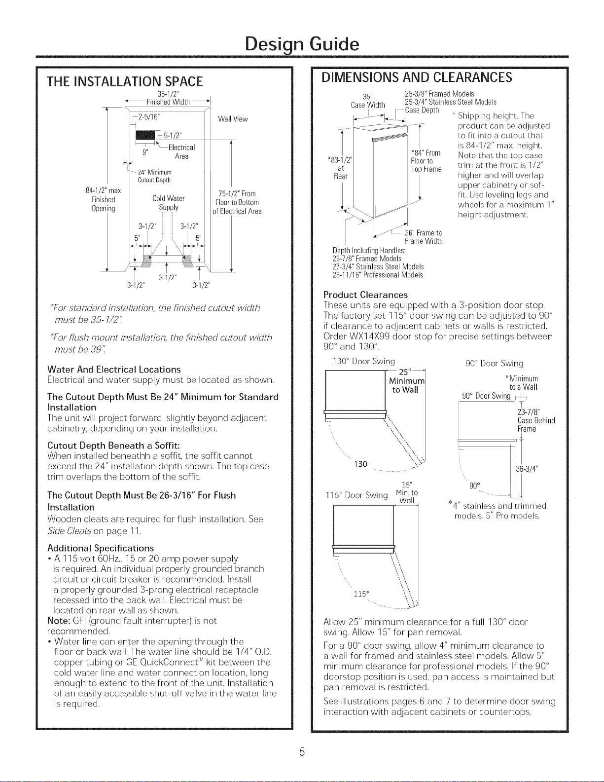
THE INSTALLATION SPACE
35-I/2"
FinishedWidth
WallView
75-1/2" From
FloortoBottom
of ElectricalArea
3-1/2" 3-1/2"
_For standard/)xsta/lat/on, the h)x/shed cutout width
must be 35- 7/2'1
_For flush mount/bsta/lat/o_ the hn/shed cutout width
must be 39'1
Water And Electrical Locations
Electrical and water supply must be located as shown,
The Cutout Depth Must Be 24" Minimum for Standard
Installation
The unit will project forward, slightly beyond adjacent
cabinetry, depending on your installation,
Cutout Depth Beneath a Soffit:
When installed beneathh a soffit, the soffit cannot
exceed the 24" installation depth shown, The top case
trim overlaps the bottom of the soffit,
The Cutout Depth Must Be 26-3/16" For Flush
Installation
Wooden cleats are required for flush installation, See
Side Cleats on page 11,
Additional Specifications
, A 115 volt 60Hz,, 15 OF20 amp power supply
is required, An individual properly grounded branch
circuit OFcircuit breaker is recommended, Install
a properly grounded 3-prong electrical receptacle
recessed into the back wall, Electrical must be
located on Fear wall as shown,
Note: GFI (ground fault interrupter)is not
recommended,
, Water line can enter the opening through the
floor OFback wall, The water line should be 1/4" O,D,
copper tubing or GE QuickConnect TM kit between the
cold water line and water connection location, long
enough to extend to the front of the unit, Installation
of an easily accessible shut-off valve in the water line
is required,
DIMENSIONS AND CLEARANCES
35"
CaseWidth
_.s _ 36"Framet0
DepthIncludingHandles:
26-7/8"FramedModels
27-3/4"StainlessSteelModels
28-11/16"ProfessionalModels
Product Clearances
These units are equipped with a 3-position door stop,
The factory set 115° door swing can be adjusted to 90°
if clearance to adjacent cabinets OFwalls is restricted,
Order WXl 4X99 door stop for precise settings between
90° and 130°,
130 ° Door Swing
"8
130
115° Door Swing Min,to
25-3/8"FramedModels
25-3/4"StainlessSteelModels
CaseDepth
*84"From Note that the top case
FI00rt0
TopFrame trim at the front is 1/2"
J
FrameWidth
25"--
_4inimum
to Wall
15"
Wall
Shipping height, The
product can be adjusted
to fit into a cutout that
is 84-1/2" max, height,
upper cabinetry or sof-
higher and will overlap
fit, Use leveling legs and
wheels for a maximum 1"
height adjustment,
90° Door Swing
90° DoorSwing
goo i
"4" stainless and trimmed
models, 5" Pro models,
*Minimum
toaWall
23-7/8"
CaseBehind
Frame
1
136-3/4"
1 .
"i i
L
Allow 25" minimum clearance for a full 130 ° door
swing, Allow 15" for pan removal,
For a 90 ° door swing, allow 4" minimum clearance to
a wall for framed and stainless steel models, Allow 5"
minimum clearance for professional models, If the 90 °
doorstop position is used, pan access is maintained but
pan removal is restricted,
See illustrations pages 6 and 7 to determine door swing
interaction with adjacent cabinets OFcountertops,
Page 6
Desi n Guide
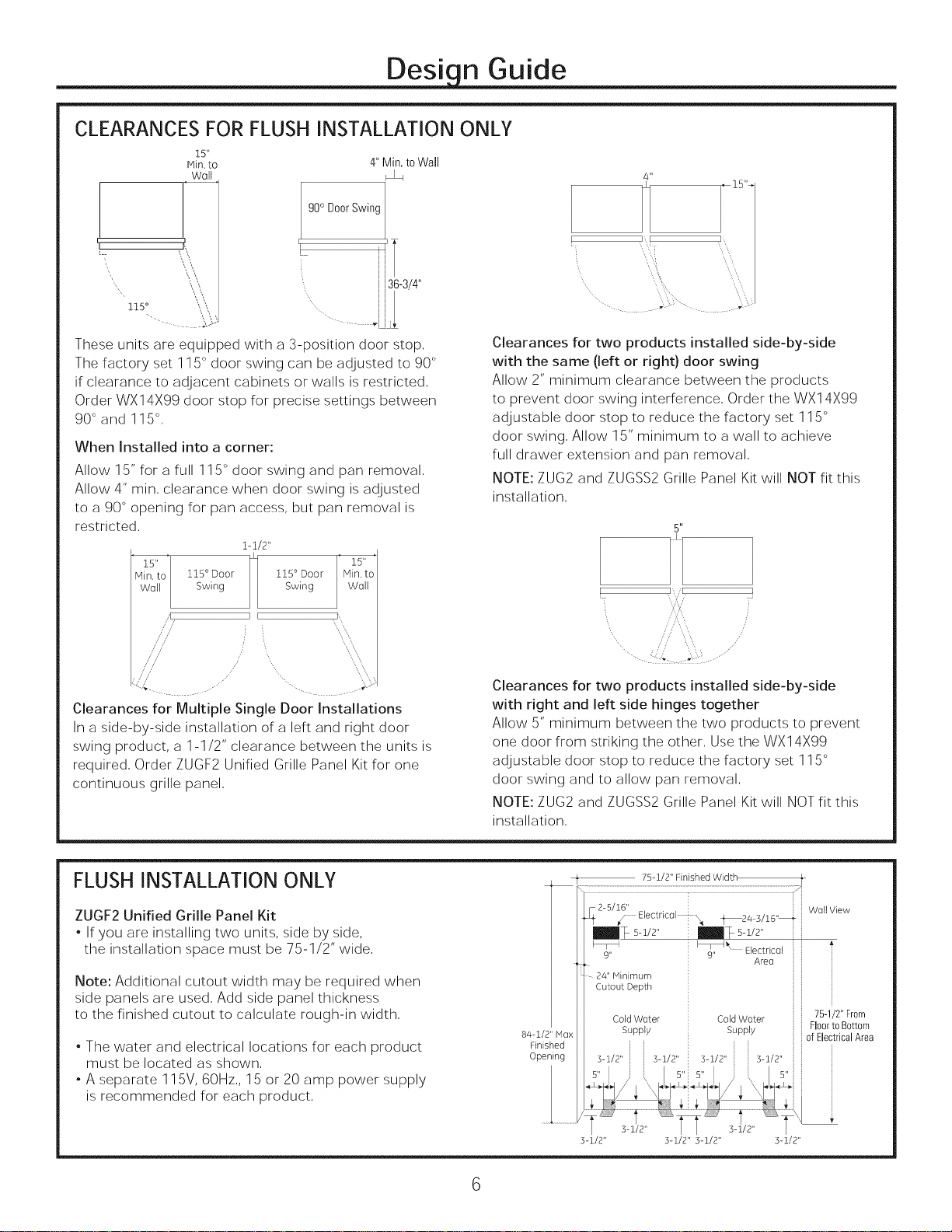
CLEARANCES FOR FLUSH INSTALLATION ONLY
15"
Iqin. to
Wall
4" Min.toWall
/4"
,J
, g0° DoorSwing
h i '_
i
136-3/4"
115 ° ", '_,
I
i
i
These units are equipped with a 3-position door stop,
The factory set 115° door swing can be adjusted to 90 °
if clearance to adjacent cabinets or walls is restricted,
Order WX14X99 door stop for precise settings between
90 ° and 115 °,
When Installed into a corner:
Allow 15" for a full 115° door swing and pan removal,
Allow 4" min, clearance when door swing is adjusted
to a 90 ° opening for pan access, but pan removal is
restricted,
1-1/2"
M 2to'
115° Door 115° Door Min. to
Wall
/"// ,,, ,, ,,
Swing Swing Woll
,1
/ /
] I
15"
i:r
Clearances for two products installed side-by-side
with the same (left or right) door swing
Allow 2" minimum clearance between the products
to prevent door swing interference, Order the WX14X99
adjustable door stop to reduce the factory set 115 °
door swing, Allow 15" minimum to a wall to achieve
full drawer extension and pan removal,
NOTE: ZUG2 and ZUGSS2 Grille Panel Kit will NOT fit this
installation,
5"
i,,/[
Clearances for Multiple Single Door Installations
In a side-by-side installation of a left and right door
swing product, a 1-1/2" clearance between the units is
required, Order ZUGF2 Unified Grille Panel Kit for one
continuous grille panel,
FLUSH INSTALLATION ONLY
ZUGF2 Unified Grille Panel Kit
, If you are installing two units, side by side,
the installation space must be 75-1/2" wide,
Note: Additional cutout width may be required when
side panels are used, Add side panel thickness
to the finished cutout to calculate rough-in width,
, The water and electrical locations for each product
must be located as shown,
, A separate 115V, 60Hz,, 15 or 20 amp power supply
is recommended for each product,
Clearances for two products installed side-by-side
with right and left side hinges together
Allow 5" minimum between the two products to prevent
one door from striking the other, Use the WX14X99
adjustable door stop to reduce the factory set 115 °
door swing and to allow pan removal,
NOTE: ZUG2 and ZUGSS2 Grille Panel Kit will NOT fit this
installation,
f
_IL2-5/16'' Wail View
75-1/2" Finished Width
Electncal _ 4_24_3/16,, _
m_ s-1/2" re%s-i/2"
91_,, _ Electrical
Cold Water
Supply
75-1/2" From
Floorto Bottom
of ElectricalArea
84-1/2" Hax
Finished
OpeFi_ng
9" Area
24" Minimum i
Cutout Depth
Cold Water
Supply
3-1/2" 3-1/2" 3-1/2" 3-1/2"
Page 7
Desi n Guide
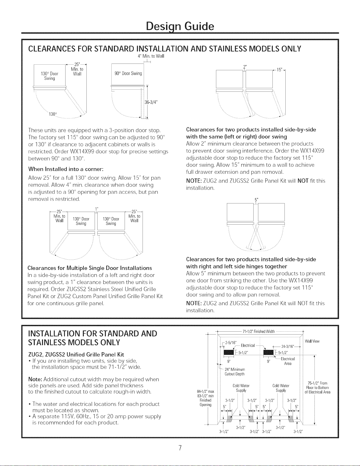
CLEARANCES FOR STANDARD INSTALLATION AND STAINLESS MODELS ONLY
4"Min.toWall
_25"_
Min.to
2"
130°SwingDoor Wall
0 DoorSwing
z
36-3/4"
1300 ; .....
.... vl
I
L
These units are equipped with a 3-position door stop.
The factory set 115° door swing can be adjusted to 90 °
or 130° if clearance to adjacent cabinets or walls is
restricted. Order WX14X99 door stop for precise settings
between 90 ° and 130 °,
When Installed into a corner:
Allow 25" for a full 130° door swing. Allow 15" for pan
removal. Allow 4" rain. clearance when door swing
is adjusted to a 90 ° opening for pan access, but pan
removal is restricted.
1"
130° Door 130° Door Wall
Swing Swing
IF ]
/'
//
--25"--
Min. to
x,,,
Clearances for Multiple Single Door Installations
In a side-by-side installation of a left and right door
swing product, a 1" clearance between the units is
required. Order ZUGSS2 Stainless Steel Unified Grille
Panel Kit or ZUG2 Custom Panel Unified Grille Panel Kit
for one continuous grille panel.
I
, L I_Z ,
I',1 I,_
Clearances for two products installed side-by-side
with the same (left or right) door swing
Allow 2" minimum clearance between the products
to prevent door swing interference, Order the WX14X99
adjustable door stop to reduce the factory set 115 °
door swing, Allow 15" minimum to a wall to achieve
full drawer extension and pan removal,
NOTE: ZUG2 and ZUGSS2 Grille Panel Kit will NOT fit this
installation.
5"
i,,/[
Clearances for two products installed side-by-side
with right and left side hinges together
Allow 5" minimum between the two products to prevent
one door from striking the other. Use the WX14X99
adjustable door stop to reduce the factory set 115 °
door swing and to allow pan removal.
NOTE: ZUG2 and ZUGSS2 Grille Panel Kit will NOT fit this
installation.
INSTALLATION FOR STANDARD AND
STAINLESS MODELS ONLY
ZUG2, ZUGSS2 Unified Grille Panel Kit
, If you are installing two units, side by side,
the installation space must be 71-1/2" wide,
Note: Additional cutout width may be required when
side panels are used, Add side panel thickness
to the finished cutout to calculate rough-in width,
, The water and electrical locations for each product
must be located as shown,
. A separate 115V, 60Hz,, 15 or 20 amp power supply
is recommended for each product,
84-1/2"max
83-1/2"min ii
Finished
Opening
t 71-1/2"FinishedWidth t
Electrical 4_ 24-3/16"_
m_ 5-1/2"
9"
ii - 24" Minimum
CutoutDepth
ColdWater
Supply
3-1/2" 3-1/2" 3-1/2" 3-1/2"
Electrical
9" Area i
ColdWater
Supply
i
WallView
75-1/2" From
Floorto Bottom
i of ElectricalArea
i
Page 8
Desi n Guide
CUSTOMIZATION BASICS:
Framed Or Overlay Panels, Custom
Handles and Accessory Kits
Professional Style Stainless Steel Models
Stainless steel wrapped refrigerators have beveled
edges and professional-style handles, These models are
shipped ready for installation,
Stainless Steel Wrapped Models
Stainless Steel wrapped models have wrapped doors
and grille panel, beveled edges, and tubular stainless
steel handles that coordinate with other Monogram
appliances, These models are shipped ready for
installation,
Trimmed Models
Trimmed models are designed to be customized with
decorative panels, Field installed custom door and grille
panels are required,
Optional Accessory Kits
. ZKHSS2: Monogram Tubular Stainless Steel handles
designed to fit 3/4" overlay panels,
. ZKHPSSI: Pro Tubular Stainless Steel handle designed
to fit 3/4" overlay panels,
. ZUG2: For side-by-side installation of two trimmed
models, This kit provides for the installation of a unified
custom grille panel to span the width of two units
using a framed or overlay panel,
. ZUGSS2: For side-by-side installation of two stainless
steel wrapped models, This kit provides a unified
stainless steel grille panel to span the width of two
units,
. ZUGF2: For side-by-side installation of two trimmed
models, This kit provides for the installation of a unified
custom grille panel to span the width of two units
using flush installation panel,
. ZTK36SDHRH: Trim kit for standard installation using
custom panels, This kit is for use with a right hand door
swing,
. ZTK36SDHLH: Trim kit for standard installation using
custom panels, This kit is for use with a left hand door
swing,
Page 9
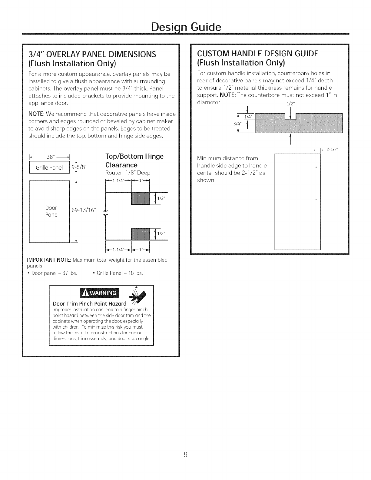
Desi n Guide
3/4" OVERLAY PANEL DIMENSIONS
(Flush Installation Only)
For a more custom appearance, overlay panels may be
installed to give a flush appearance with surrounding
cabinets, The overlay panel must be 3/4" thick, Panel
attaches to included brackets to provide mounting to the
appliance door,
NOTE: We recommend that decorative panels have inside
corners and edges rounded or beveled by cabinet maker
to avoid sharp edges on the panels. Edges to be treated
should include the top, bottom and hinge side edges.
I_ 38" _1
i Gri"ePone'i '8
Door 69-!3/!6"
Ponel
CUSTOM HANDLE DESIGN GUIDE
(Flush Installation Only)
For custom handle installation, counterbore holes in
rear of decorative panels may not exceed 1/4" depth
to ensure 1/2" material thickness remains for handle
support, NOTE: The counterbore must not exceed 1" in
diameter, 1/2"
t
_2-&/2"
Minimum distance from
handle side edge to handle
center should be 2-1/2" as
shown.
IMPORTANT NOTE: Maximum total weight for the assembled
panels:
. Door panel - 67 Ibs, . Grille Panel - 18 Ibs,
Door Trim Pinch Point Hazard
Improperinstallationcanleadto a finger pinch
pointhazardbetweenthesidedoortrim andthe
cabinetswhen operatingthe door,espeda]ly
with children.To minimizethis riskyoumust
followthe installation instructionsfor cabinet
dimensions,trim assembly,anddoorstop angle.
Page 10
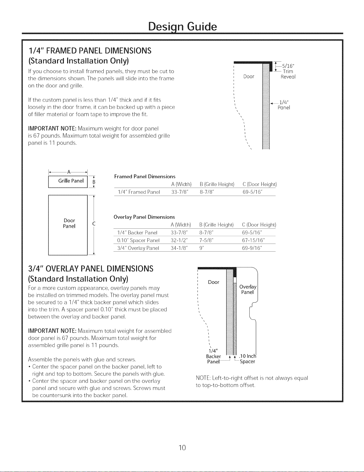
1/4" FRAMED PANEL DIMENSIONS
Desi n Guide
(Standard Installation Only)
Ifyou choose to install framed panels, they must be cut to
the dimensions shown, The panels will slide into the frame
on the door and grille,
If the custom panel is less than 1/4" thick and if it fits
loosely in the door frame, it can be backed up with a piece
of filler material or foam tape to improve the fit,
IMPORTANT NOTE: Maximum weight for door panel
is 67 pounds, Maximum total weight for assembled grille
panel is 11 pounds,
I A_l
[ Grille Panel ]]
Door
Panel
Framed Panel Dimensions
1/4" Framed Panel 33-7/8" 8-7/8" 69-5/16"
Overlay Panel Dimensions
1/4" Backer Panel 33-7/8" 8-7/8" 69-5/16"
0,10" Spacer Panel 32-1/2" 7-5/8" 67-15/16"
3/4" Overlay Panel 34-1/8" 9" 69-9/16"
m, bs/!6, '
Door
iiiiiiiiiiiiiiiiiiiii!iiii!iiii!..............1/4"
iiiiiiiiiiiiiiiiiiiil
A (Width) B (Grille Height) C (Door Height)
A (Width) B (Grille Height) C (Door Height)
LTrim
Reveal
Panel
3/4" OVERLAY PANEL DIMENSIONS
(Standard Installation Only)
For a more custom appearance, overlay panels may
be installed on trimmed models, The overlay panel must
be secured to a 1/4" thick backer panel which slides
into the trim, A spacer panel 0,10" thick must be placed
between the overlay and backer panel,
IMPORTANT NOTE: Maximum total weight for assembled
door panel is 67 pounds, Maximum total weight for
assembled grille panel is 11 pounds,
Assemble the panels with glue and screws,
. Center the spacer panel on the backer panel, left to
right and top to bottom, Secure the panels with glue,
. Center the spacer and backer panel on the overlay
panel and secure with glue and screws, Screws must
be countersunk into the backer panel,
Door
°°cke ooe,.... 2
NOTE: Left-to-right offset is not always equal
to top-to-bottom offset,
10
Page 11

Design Guide
SIDE PANELS
Side panels must be used whenever the sides of the unit
will be exposed, The 1/4" side panels will slip into the
side case trim, Secure the panels to the unit with stick-
on hook and loop fastener strips, Order the side panels
from the cabinet manufacturer,
, Cut a notch in the top front corner as shown to allow
clearance for corner keys in the front side trim,
* Depending on
installation height,
_84"
ZUG2 GRILLE PANEL DIMENSIONS
The ZUG2 unified grille panel kit provides for the
installation of a framed or overlay grille panel,
A
Grille Panel T
Framed Panel Dimensions
A (Width) B(Height)
1/4" Framed Panel 69-7/8" 8-7/8"
Overlay Panel Dimensions
A (Width) B(Height)
1/4" Backer Panel 69-7/8" 8-7/8"
0,10" Spacer Panel 68-1/2" 7-5/8"
3/4" Overlay Panel 70-1/8" 9"
IMPORTANT NOTE: The maximum weight for the
unified grill is 25 pounds,
SIDE CLEATS
(Flush Installation Only)
Wood cleats are required to be installed vertically
down both sides of the cabinet opening to provide
depth stop for the refrigerator when installed into the
opening,
The front of the cleat should be installed 5-1/4" from
the front of the cabinet opening,
Finished
CJeat
Assemble the overlay panels in the same manner
as the door panel,
ZUGF2 GRILLE PANEL DIMENSIONS
(Flush Installation Only)
The ZUGF2 unified grille panel kit provides for the
installation of a flush grille panel,
74-1/2"
Grille Panel
T
9-5/8"
11
Page 12

Desi n Guide
Refrigerator
or Freezer 23-7/8"From
Rearof
Ink
Frameless Cabinets: The case trim
overlaps cabinets at the top and sides,
Therefore, frameless cabinets may require filler
strips to prevent interference with cabinet door
swing, The opening must allow for filler strips,
Case
Trim
1/4"
1/2"
3/4"
1-1/4"
1-3/4"
1-1/2"
2-1/4"
CabinetFront
3/4" Overlay
, Panel
"",,,, (NominalSize)
Top View
130 ° DOOR SWING
(Standard Installation Only)
Scale 1:1
Door
12
Page 13

Desi n Guide
Refrigerator
or Freezer
Frameless Cabinets:
CaseTrim
The case trim overlaps
cabinets at the top and sides,
Therefore, frameless cabinets
may require filler strips
to prevent interference
with cabinet door swing,
23-7/8" The opening must allow
FromRearof for filler strips,
Unit
u
.............. t--. 1/4"
i
i
u
...... L 1/2"
....................... 3/4"
i u
,.... -.... •.... ............ 1"
i u i
Cabinet Front
/
/
/
/
/
/
1-1/4"
Top View
90 ° DOOR SWING
(Standard
installation Only)
Scale 1:1
1-1/2"
Door
3/4" Overlay
Panel
(Nominal Size)
13
Page 14

Installation Instructions
TOOLS AND MATERIALS REQUIRED
, Tin snips to cut banding
, #2 Phillips screwdriver
, Stepladder
, Drill and 1/2", 3/16" bits
, Bucket
,1/4", 1/2", 5/16", 7/16" socket
, Level
, Safety glasses
, Appliance hand truck
, Pliers
, Tubing cutter
, Stud finder
,7/16" and 1-1/4" open-end wrench
,1/4" copper water line tubing or GE SmartConnect TM
Refrigerator Tubing kits
, Water shut-off valve (optional but recommended)
, Custom panels for door and grille panel
, Screws to secure unit to cabinetry
, Stick-on hook and loop fastener strips for
1/4" side panels
, Flush install panel bracket kit
, Case Trim
GROUNDING THE UNIT
----_}_ Electrical Shock Hazard.
Failure to follow these instructions can result in death,
fire, or electrical shock,
The power cord of this appliance is equipped with a
3-prong (grounding) plug which mates with a standard
3-prong (grounding) wall receptacle to minimize the
possibility of electric shock hazard from this appliance,
Have the wall outlet and circuit checked by a qualified
electrician to make sure the outlet is properly grounded,
Where a standard 2-prong wall outlet is encountered, it
is your personal responsibility and obligation to have it
replaced with a properly grounded 3-prong wall outlet,
DONOT,UNDERANY
CIRCUMSTANCES,CUTORREMOVE
THETHIRD(GROUND)PRONG
FROMTHEPOWERCORD,
DONOT USEANADAPTERPLUG
TO CONNECTTHE REFRIGERATOR
TOA 2-PRONGOUTLET,
DONOT USEAN EXTENSIONCORDWITH THIS
APPLIANCE,
HARDWARE SUPPLIED
. Water filter bypass plug
. Anti-Tip brackets
.3 lag screws
,2 Hair Pin Cotters
,4 washers
,5 toggles with bolts
, Toekick
FLOORING
For proper installation, this product must be placed
on a level surface of hard material that is at the same
height as the rest of the flooring, This surface should be
strong enough to support a fully loaded refrigerator or
freezer, or approximately 1,200 Ibs, per unit,
NOTE: Protect the finish of the flooring, Cut a large sec-
tion of the cardboard carton and place under the prod-
uct where you are working,
NOTE:Not recommended for installation on carpeted flooring,
LA TERRE DE L'UNITI e
Risque de choc electrique.
Le non-respect de ces instructions peut entrainer des
risques d'incendies, des chocs electriques ou la mort,
Le cordon d'alimentation de cet appareil est equipe
d'une fiche h trois broches (pour une mise h la terre)
qui s'adapte h la prise de courant standard h 3
broches (pour une mise h la terre) pour minimiser les
risques de chocs electriques par cet appareil,
Faites verifier la prise murale et le circuit electrique par
un electricien qualifie pour s'assurer que le systeme est
correctement mis h la terre,
Dans le cas d'une prise biphasee, I'installateur a la
responsabilite et I'obligation de la remplacer par une
prise triphasee correctement mise h la terre,
NECOUPEZPASOU N'ENLEVEZ
PAS,SOUSAUCUN PRETEXTE,
LATROISIEMEBROCHEDE
MISEA LATERREDU CORDON
D'ALIMENTATION,
N'UTILISEZPASD'ADAPTATEUR
POURBRANCHERLE
REFRIGERATEURA UNEPRISEBIPHASEE,
N'UTILISEZPASDE RALLONGEAVECCETAPPAREIL,
14
Page 15

PARTS IDENTIFICATION:
Installation Instruction
h............. t
Panel Bracket, Top Right
Panel Bracket, Bottom Left
Panel Bracket, Bottom
Right
Panel Bracket, Top Left
Panel Bracket, Top
Trim, Handle Side
Visor
Trim, Handle Side
Cover
Trim, Freezer Hinge
Side
. TOPI_HI.GESAREONT,ELEF
BO_O,,_IFHINGESAREO.THELE_
Panel Bracket, Bottom
Door Bracket (4);
Installed on door
Door Panel Template
Grille Template
Door Trim Top
Door Trim, Bottom
Trim, Case, RH Side
Trim, Case, LH Side
15
Page 16

Installation Instructions
ISTEP11REMOVEPACKAGING
_Tip Over Hazard.
Product is much heavier at the top than at the bottom
- be careful when moving, When using a hand truck,
handle from side only,
1_V't_ Risque de basculement
Le produit est beaucoup plus Iourd en haut qu'en bas, II
faut 6tre prudent Iors des deplacements, Si un diable est
utilise, il faut soulever le refrigerateur sur le cote seule-
ment,
. Carefully cut banding at the top and bottom, remove
outer carton,
. Slide out back corner posts (2),
. Slide carton off top of cabinet,
NOTE: IT IS NOT NECESSARY TO LAY CABINET DOWN
IN ORDER TO REMOVE SKID!
NOTE: DO NOT ATTEMPT TO ROLL UNIT OFF SKID,
STEP 2 INSTALL WATER LINE
. A cold water supply is required for automaticicemaker
operation, The water pressure must be between 40 and
120 p,s,i,
. Route 1/4" OD copper or GE SmartConnect TMplastic
tubing between house cold water line and the water
connection location,
. Tubing should be long enough to extend to the front of
the unit, Allow enough tubing to accommodate bend
leading into the water line connection,
NOTE: The only GE approved plastic tubing is supplied in
the GESmartConnect TMRefrigerator Tubing kits, Do not
use any other plastic water supply line because the line
is under pressure at all times, Other types of plastic may
crack or rupture with age and cause water damage to
your home,
GE SmartConnect TMRefrigerator Tubing Kits are available
in the following lengths:
2' (,6 m) WXOSXlO002
8' (2,4 m) WXOSXlO006
15' (4,6 m) WXOSXlO015
25' (7,6 m) WXOSXlO025
Custom
HandleTrim
ii Anti-Tip
Bracket
Y
Remove
Tie-D0wns
J
J
. The unit is secured to the skid with 4 slotted tie-down
straps, Remove the four 5/16" bolts from the base
channels in the tie-downs,
. Remove toekick, custom handle trim, and wall brack-
et, Set aside for final installation,
. Lift the unit off the skid with an appliance dolly,
Handle from the sides,
. Remove the four 7/16" bolts securing the tie-down
brackets to the skid,
ColdWater
Supply
3-1/2" 3-1/2"
Shut off the main water supply.
Turn on the nearest faucet long enough to clear the line
of water,
. Install a shut-off valve between the icemaker water
valve and cold water pipe in a basement or cabinet,
The shut-off valve should be located where it will be
easily accessible.
. Turn on the main water supply and flush debris, Run
about a quart of water through the tubing into a
bucket, Shut off water supply at the shut-off valve,
NOTE: Saddle type shut-off valves are included in many
water supply kits, Before purchasing, make sure a saddle
type valve complies with your local plumbing codes,
NOTE: Commonwealth of Massachusetts Plumbing
Codes 248CMR shall be adhered to, Saddle valves
are illegal and use is not permitted in Massachusetts,
Consult with your licensed plumber,
STEP3 INSTALL SIDE PANELS
Skip this step when not using side panels
If you are using 1/4" side panels, they should be inserted
into the case trim,
Fasten the panels to the unit with stick-on hook and
loop fastener strips before setting unit in place,
16
Page 17

Installation Instructions
ISTEP 41 INSTALL CASE TRIM
Install case trim using supplied right hand and left hand
case trim pieces and case trim screws, Attach case trim
to each side of case as shown in illustration using case
trim screws in holes provided down each side of case,
STEP 5 INSTALL ANTI-TIP BRACKET
(cont.)
Standard/Stainless Installation Only
, The kit supplied with the unit contains 2 lag bolts and 4
toggles with bolts, The wall bracket will be attached to
the wall in 4 places,
, Measure the opening where the unit is to be installed,
Mark the center with a vertical line,
, Measure up 81 1/2" from the floor, Mark this point on
the wall,
, Using a level, draw a horizontal line on the wall at this
height,
, Locate at least 2 studs on the back wall, Mark these
points on the horizontal line,
, Place the bottom of the wall bracket with tabs on the
horizontal line, Align the center notch on the bracket
with the center line on the wall,
ISTEP5 ]INSTALL ANTI-TIP BRACKET
_Tip Over Hazard,
The unit is top-heavy and must be secured to prevent the
possibility of tipping forward,
__ Risque de basculement
L'appareil menager est beaucoup plus Iourd en haut et il
faut le maintenir en place pour eviter la possibilite de son
basculement vers I'avant,
, Cut a 1/2" x 4" block, 35" long, ,, _
, Measure and mark under the soffit,
5-1/4" from the front edge of the 84
cabinet From__
Hoor/
, Secure the wood block to under the to
soffit,FromthebottomoftheblockBottom
84", See the illustration,
11
I¸,¸¸¸¸¸,,,,
81-1/2"
ToFloor
• The anti-tip wall bracket has a series of holes, Select 2
holes that match with the located studs, Make sure the
holes selected are on the center of the studs, Mark the
wall at these points,
Side View
17
Page 18

Installation Instructions
I STEP 5]
INSTALL ANTI-TIP BRACKET
(Standard/Stainless Installation
only) (cont.)
Center WallBracket
: ]
i : ...........
I JJ°
i ..............ij_ ....
TwoAdditional
H01eLocationsat
EndsofBrackets
• Mark an additional hole at each end of the bracket, If one
of the studs is closer to the end of the bracket, mark an
additional hole towards the center of the bracket,
/
Line on Wall
WallStuds
Center
I J/ ' •
/ i
i
/
.... -oJ .o-Io_
I I
_F
/
Line OnWall
. Gently pull back at the ends of the plastic straps to make
the channel rest flush behind the wall,
. Hold the ends of the straps in one hand and slide the plas-
tic cap along the straps until the flange of the cap is flush
with the wall,
. Place your thumb between the plastic straps and bend up
and down to snap the straps off at the wall,
Install Screws and Bolts:
. Have someone hold the wall bracket centered in place
with each of the holes aligned with the correct opening in
the bracket and level with the horizontal line,
. Insert the lag screws through the bracket and into the
stud, Tighten with a wrench,
" WoodStud
• Drill 1/2" holes into the wall board at the locations marked
for the toggles to be mounted (not the stud markings),
• Drill 3/16" holes into wooden studs where marked, If steel
stud construction, drill 1/2" holes into the studs where
marked, You will use 2 toggles with the metal studs,
Install Wall Toggles:
The wall toggles and bolts can be ordered as Service Kit
#WR49X10193, Wall toggles are installed in the drywall
and metal studs for stability, Install the wall toggles as fol-
lows:
. Drill 1/2" holes at the wall markings made in the holes at
the ends of the wall bracket,
. Hold the metal channel flat against the plastic straps
and slide the channel through the hole,
PlasticStraps
Metal Channel
Anti-TipWall Bracket
Insert the bolts into the toggle by hand until snug,
Tighten with a wrench,
Drywallor
SteelStud
B01t
Anti-TipWall Bracket
]
18
Page 19

Installation Instructions
STEP 5 INSTALL ANTI-TIP BRACKET
(Standard/Stainless
Installation only) (cont.)
Remove Grilles for Access to Anti-Tip Locking Hooks
Fresh Food Unit
* Open the access door,
* Remove the 4 screws from the grille,
* Pull the bottom of the grille forward, down and out
to remove,
q, )
Screws
Freezer Unit
* Open the access door,
* Remove the 4 screws from the grille,
* Pull the bottom of the grille forward, down and out
to remove,
X, )
Power Cord
Locate the power cord inside the left cavity, If it has not
been adjusted so the plug is easily accessible,
do so now,
"L" Bolt
\
\
\
\
PowerCordLocation
Move Unit into Final Position
* Move appliance toward its final installed location,
Align the tabs on the wall bracket with the openings
in the back of the unit,
* The unit has "L" bolts in the upper left and right
corners inside of the access compartment, These
bolts will interlock with the wall bracket and secure
the unit using the washers and hair pin cotters
in the hardware kit once the unit has been leveled
and is in the final position,
Screws
_o
19
Page 20

Installation Instructions
STEP6 LEVEL UNIT
All models have 4-point leveling, The front is supported
by leveling legs; the rear is supported by adjustable
wheels, Both are accessible from the front of the unit,
. To level the back of the unit, turn the 7/16" hex nut
located above the front wheels, Turn clockwise
to raise or counterclockwise to lower the unit,
, For front leveling, use a 1-1/4" open-end wrench,
, Adjust height of unit to match installation cutout
opening 84-1/2", The unit should be level and plumb
with cabinetry,
NOTE (Flush Installation Only): Raise appliance until
the case top comes in contact with the 1/2" spacer
block mounted to the underside of the cabinet soffit,
Appliance should be level at fully raised position,
/l
HexNut Adjusts -.!_ll I
RearWheels
ISTEP7 ISECUREAPPLIANCE
TO CABINETRY
Flush Installation Only
Whenever possible, perform this step for anti-tip security,
or when anti-tip brackets cannot be used, The appliance
must be secured to prevent tipping,
, Raise the grille panel to access the machine compart-
ment,
, For flush inset installation only, drill a hole in the case
top and drive a screw through the top into the adjacent
1/2" block,
Drive Screws
Through Case Trim Into
Adjacent Cabinets
The rear leveling wheels and front leveling legs are
limited to a maximum height adjustment of 1", If the
installation requires more than 84-1/2" height, the
installer should elevate the unit on a sheet of plywood
or runners, Cabinetry trim could also be added across
the top of the opening to shorten the opening, If you
attempt to raise the unit more than 1", you will damage
the front leveling legs and the rear leveling wheels,
Les roues de nivellement arriere et les pattes de
nivellement avant permettent un reglage maximal
de 25 mm (1 po), Si I'ouverture pour I'appareil
manager a une hauteur superieure _ 2,15 m (84-1/2
po), I'installateur doit elever I'appareil manager sur
une feuille de centre-plaque ou des glissieres, II est
egalement possible d'ajouter des baguettes de finition
des placards sur le haut de I'ouverture afin de la
reduire, Lever I'appareil manager de plus de 25 mm
(1 po) endommage les pattes de nivellement avant et
les roues de nivellement arriere,
2O
Page 21

Installation Instructions
STEP 81 SECURE UNIT TO WALL
Standard and Stainless Installation Only
. The "L" rods can be found in the upper left and right
corners of the unit in the access compartment, Look
through the access compartment to make sure the rods
line up with the anti-tip bracket,
. There are 2 washers and a hair pin cotter per rod,
Remove the washers and hair pin cotter from the end of
the rod,
. Rotate and move the "L" rod into the slot in the anti-tip
bracket tab, Once it is in the slot, rotate the "L" rod so
the hook portion is pointing down, The holes at the front
end of the rod should be in a vertical position, Do this to
both sides,
. Pull out on the end of the rod to make sure it is secure in
the bracket,
. Locate the hole on the rod that is closest to the unit, A
hair pin cotter will be put through this hole to secure the
rod, If this hole appears to be too far away for a snug fit
against the unit, add the washers one at a time until the
pin will fit tightly into the hole,
. Align the straight section of the pin with the hole from
the underside of the rod, Push the pin up until it snaps
into position, Pliers may be used, NOTE: The hair pin
cotter must be vertical when this step is completed to
ensure the "L" rod is engaged in the bracket,
. Check the rod for tightness by pulling forward, If the rod
moves, remove the hair pin cotter and place another
washer on the rod, Reinsert the pin,
. Replace the grille panel,
._._<,_.::_ .............
,, . , . r
L RodP0mtlngDown _ lX
EngagedinBracket
"L" Rod
0
/
/
/
WallBracket
"L"Rod
\
0
21
Washer
Hair Pin Cotter
is Vertical
Page 22

Installation Instructions
[STEP9 ADJUST DOOR SWING
NOTE: This appliance has a 3-position door stop, When
space does not allow the door to swing open fully to
115 °, you may change the door swing to a 90 ° opening,
A 130 ° door swing is available for standard installation
only, Skip this step if door opening is satisfactory for
your installation situation.
Door Swing Pin Location
for 130 °
Door Swing
Pin Location
as Shipped
for 115°
Door Swing
STEP10 REMOVE DOOR TRIM - FLUSH
INSTALLATIONONLY
Use the supplied Torx wrench or TIO Torx head driver
to remove all exposed trim screws securing aluminum
trim to door. Save all trim and screws as they will be
replaced in a later step.
1, Remove 6 screws and trim from the hinge side of the
door,
2, Remove 4 trim screws on vertical handle side of the
door to release handle cover trim, Remove the handle
cover trim to expose handle visor trim underneath,
3 Remove 4 additional trim screws from handle visor
trim, Once screws have been removed, remove handle
visor trim,
Handle side
_I trim Handle
visor trim
, Open the door to view the bottom hinge, Note the door
stop pin locations, The pin is factory-installed in the
115 ° position,
, Close the door, From below, use pliers to unscrew the
door stop and reinstall into the 90 ° position,
22
Page 23

Installation Instructions
[STEP 111 LAYOUT DECORATIVE DOOR PANELS
Decorative wood panels must be cut to a thickness of
3/4". The dimensions of each panel can be determined
by referring to the specs provided with appliance.
Panels must be predrilled to prevent accidental splitting
or cracking of wood when attaching to door brackets in
the next step.
1, Cut door panel to specified dimensions (as noted on
page 8 under Design Guide),
2, Lay the door panel face down on a non-scratch sur-
face,
3, Mark a vertical centerline on the backside of the door
panel,
4, Lay supplied panel TEMPLATE (attached to side case
of appliance) on the back of the door panel with the
lettering face up, See illustration to ensure proper
template placement, Align the top, side, and centerline
of the template with the top, side and centerline of the
door, Tape the template to the panel using masking
tape to temporarily secure it in place,
Panel is face down on
TOP a non-scratch surface,
You will be drilling on
qe BACKof the panel,
Template is
of the panel, Hinge
should be on
side of where the hinge is
located on the unit since this
is the BACK of the panel,
- FLUSH INSTALLATION ONLY
6, Using a pencil, trace the outline of the notch out of the
template at the top corner of the door, This mark will
provide a guide for routing wood to provide relief for
door hinge at top of door panel,
7, Remove the tape from the panel, Slide the templates to
the bottom of the panel aligning the bottom, sides, and
centerline of the panel with the bottom, sides and cen-
terline of the template, Tape in place,
Panel is face down on
a non-scratch surface,
You will be drilling on
BACK of the panel,
Template is aligned with
bottom of the panel, Hinge
cutouts should be on the
OPPOSITE side of where
hinge is located on the unit
since this is the BACK of the
panel,
,
Using a 1/8" wood drill bit, drill pilot holes into the door
panels 1/4" deep through only the bottom group of
holes in the templates, Four holes will be drilled into
the bottom corners of each door,
,
Using a pencil, trace the outline of the notch out of the
template at the bottom corner of each door, This mark
will provide a guide for routing wood to provide relief
for door hinge at bottom of door panel,
BOTTOM
,
Using a 1/8" wood drill bit, drill pilot holes into the door
panel Y4" deep through only the top group of holes in
the templates, Four holes will be drilled into the upper
corners of the door panel,
\
10, Route out the traced areas on the rear of each panel
1/4" deep and discard the door panel templates,
Preparation for handles
1, Lay out the location of the custom handle on the back
of the door panel,
2, Counter-sink the handle screw locations on back of
the pane to avoid interference with the door frame,
Countersink 1/4" to maintain 1/2" minimum material
thickness,
23
Page 24

Installation Instructions
[STEP 12 ATTACH BRACKETS TO PANELS - FLUSH INSTALLATION ONLY
Locate wood panel brackets and wood panel screws in
Flush Inset Hardware Kit located inside the appliance
drawer. These brackets will install to rear of decorative
wood panels to provide attachment to door brackets
already installed on doors.
1, Align the four tapered holes in the top left hand panel
bracket with the four pilot holes at the top hinge side
of the door panel making sure the angled portion of the
bracket is facing the perimeter of the door, Fasten the
bracket using four screws,
2, Align the four tapered holes in the bottom left hand
panel bracket with the four pilot holes at the bottom
hinge side of the door panel making sure the angled
portion of the bracket is facing the perimeter of the
door, Fasten the bracket using four screws,
Top Left Top Panel
Panel
Bracket
Bracket
Top
3, Align the four tapered holes in one of the top panel
brackets with the four holes in the top of the door
panel on the handle side, Fasten the bracket using four
screws,
4, Align the four tapered holes in one of the bottom panel
brackets with the four holes in the bottom of the door
panel on the handle side, Fasten the bracket using four
screws,
5, Install the custom handle on the front side of the door
panel, A washer should be used in the countersink hole
on the back of the panel,
Door Panel is face
down on a non-scratch
surface,
Hinge Side
of Panel
Bottom Left
Panel Bracket
Bottom Panel
Bracket
24
Page 25

Installation Instructions
STEP13 HANG DECORATIVE DOOR PANELS - FLUSH INSTALLATION ONLY
Panel with attached brackets will mate with steel
brackets already attached to top, sides, and bottom of
the door. Each bracket attached to the door will have
two machined screws recessed inside the door to provide
anchoring points for wood panel brackets to install onto
the doors.
1, Lift the decorative panel to hang the panel on the door,
Angle the bottom of the panel slightly away from the
door, The brackets mounted at the top of the door panel
will lay over the top of the brackets mounted at the top
of the door, Allow the flanges of the door brackets to
slide into the slot at the top of the panel brackets and
gently allow the bottom edge of the panel to lay against
the door as it hangs freely,
,
Thread set screws into each of the panel brackets
attached to the door, Hinge side brackets will have 2
set screws each, going into the door, The handle side
brackets will each have 1 set screw going into the door,
Each panel bracket has a tab that is aligned with a tab
on the door bracket, Each of these will have a set screw
threaded into them (see illustration),
I
,
Adjust the panel by pushing it flush against the door,
3,
Using supplied washer-head screws, secure panel
brackets mounted to the rear of the wooden panels to
the door; top, side and bottom,
Each screw should be tightened until snug, and then
backed off 2-3 turns to allow for fine tuning adjustment,
NOTE: If screws are fully tightened at this stage, fur-
ther panel adjustment will not be possible,
25
Page 26

Installation Instructions
[STEP14 LAYOUT DECORATIVE GRILLE
PANEL - FLUSH INSTALLATION
ONLY
Grille area will also have decorative wood panel
attached to installed steel bracket. Pilot holes are nec-
essary to prevent splitting and cracking of wood panel.
1, Cut wooden grille panel to specified dimensions as
noted on 12,
2, Lay the grille panel face down on a non-scratch
surface,
3, Mark a vertical centerline on the back side of the grille
panel,
4, Lay supplied TEMPLATE to the back of the grille panel
with the lettering face up, Align the top, side, and cen-
terline of the template with the top side and centerline
of the door, Tape the template in place using masking
tape,
5, Using a 1/8" wood drill bit, drill pilot holes into the grille
panel Y4" deep,
6, Remove tape and discard template,
STEP 15] INSTALL GRILLE PANEL - FLUSH
INSTALLATION ONLY
1, Pull grille panel bracket in an outward motion allowing
it to swing out and up to the fully open position,
2, Lay the grille panel on top of the grille panel bracket
and align the pilot holes with the bracket holes from the
underside,
3, Fasten the grille panel to the grille panel bracket using
provided screws in bracket hardware kit,
26
Page 27

Installation Instructions
[STEP 16 ADJUST DECORATIVE PANELS - FLUSH INSTALLATION ONLY
The panel can be adjusted approximately 1/8" both left
and right, up and down, as well as outward from the
door to provide planar appearance with cabinets.
NOTICE: Misaligned panels from incorrect drilling or incor-
rect cut dimensioning may result in less possible adjust-
ment as well as possible interferences with other attached
panels and/or hardware,
1, The gap between the outside edge of the door panel
and the cabinet opening should be 9/16", Adjust panel
until specified gap is maintained,
Door panel and hood
panel should be flush with
the fronts of the cabinets.
.,_.--9/16" -,_.-9/16"
,
Check that the door panel is in plane with the face of
the cabinets, The panel can be adjusted outward by
turning the set screw threaded into the tab of the door
bracket at the top and bottom of the door clockwise
until the face of the panel is in the same plane as the
cabinetry,
flush with cabinetry, ItlV
,
Check the fhshness of the panel with the cabinetry,
If the grille is not flush, adjustments can be made by
loosening the screws in the slots on the hinge and mov-
ing the panel in or out, Once all adjustments are made,
retighten screws and close the grille,
,
Turn the set screw at the hinge side (top and bottom) of
the appliance clockwise to adjust the door panel toward
the edge of the door opening, Check the gap by closing
the door,
Turn set screw on
_._._.. hinge side, top and
_'-,,_L__. bottorn, clockwise
"_<t_ _omove_oward_he
_. door opening,
Use these screws
to adjust the grille
panel in or out -
both sides,
27
Page 28

Installation Instructions
[STEP16 ADJUST DECORATIVEPANELS
- FLUSH INSTALLATION ONLY
(Cont)
,
Make the final vertical adjustment of the door panel,
Using the set screw at the top of the door, turn
clockwise until the desired gap between the grille
panel bottom and top panel of the door appears
Turn set screws on top and bottom
of door to move panel up or down
for desired gap with grille panel
bottom,
satisfactory,
,
Tighten all washer-head screws (NOT SET SCREWS)
firmly to secure brackets and adjustments in place,
Start with bottom edge washer-head screws to
provide support of the door panel, Next, moving on to
top edge to prevent panel from moving from aligned
position, Finish by tightening hinge side washer-head
screws, NOTE: Over-tightening washer-head screws
may result in bending wood panel brackets as well as
misaligning wood door
panels, _"
,
Drive the door anchor
screws through the
two white plastic pock-
ets in the side of each
door and into the door
panel (4 each door) to
prevent panel warping
over time,
STEP 17i REPLACETRIM- FLUSH
INSTALLATION ONLY
1, Replace trim and 6 screws on hinge side of the door,
2, Replace handle visor trim and four screws on the han-
dle side of the door,
3, Replace trim cover and four screws over visor trim on
the handle side of the door,
Handle
side trim
Handle
visor trim
Hinge side
,/
28
Page 29

Installation Instructions
STEP 18 CONNECT WATER SUPPLY
(FREEZERMODELS ONLY)
I
/,
"\ House Freezer /
_Water Supplg Water Supplg_.
, Locate and bring the tubing to the front of the cabinet,
, Turn the water on to flush debris from the line, Run
about a quart of water through the tubing into a
bucket, then shut off the water,
Copper Tubing:
, Slip a 1/4" nut and ferrule (provided) over both ends
of the copper tubing, Insert the tube into the union
fitting on the unit and tighten the nut to the union,
, Turn on the water to check for leaks,
GE SmartConnect T" Tubing:
NOTE: The only OE-approved plastic tubing is supplied
in the GE SmartConnect Refrigerator Tubing kits, Do
not use any other plastic water supply line because the
line is under pressure at all times, Other types of plastic
may crack or rupture with age and cause water dam-
age to your home,
, Insert the molded end of the tubing into the appliance
or freezer connection, Tighten the compression nut
until it isjust hand-tight,
, Tighten one additional turn with a wrench,
Overtightening can cause leaks!
, Turn on the water to check for leaks,
NOTE: Make sure excess tubing length does not
interfere with the toekick installation,
ISTEP191START ICEMAKER
(FREEZERMODELS ONLY)
Icemaker
/
Power
Switch
, Slide the switch to ON, The icemaker will begin
operation automatically,
, Be sure nothing interferes with the sweep of the feeler
arm,
, Discard the first full bucket of ice cubes,
, To turn the icemaker off, slide the switch to OFF,
Feeler Arm
ISTEP201 INSTALL TOEKICK
, Locate the supplied toekick (shipped taped to
the side of the appliance), Install the toekick assembly
with the 2 screws provided, adjust to the desired
height and tighten the screws,
%
IMPORTANT: A custom toekick can be installed to
match or complement the surrounding cabinetry but
can NOT cover the horizontal vent slots of the factory
toe kick,
%
29
Page 30

Notes
30
Page 31

Notes
31
Page 32

31-49062-2
224D2601 P002
01-15 GE
Printed in the United States
NOTE: While performing installations described in this
book, safety glasses or goggles should be worn.
For Monogram ® local service in your area, call
1,800,444 ,I 845,
NOTE: Product improvement is a continuing endeavor at
General Electric. Therefore, materials, appearance and
specifications are subject to change without notice.
GE
Appliances
AppliancePark
Louisville,KY40225
GEAppfiances.com
 Loading...