

Page 1

Installation
Instructions
Instructions
d’installation
30″ Stainless Steel
Gas Cooktops
Natural Gas Model:
ZGU384N
LP Gas Model:
ZGU384L
Questions?
Call 800.GE.CARES
or Visit our Website at:
www.monogram.com
Appelez le Centre de réponse 1.800.561.3344
ou visitez notre site Web à l’adresse :
www.electromenagersge.ca
31-10635-2
08-07 JR
Surfaces de cuisson
au gaz de acier
inoxydable de 30 po
(76 cm)
Modèle à gaz naturel :
ZGU384N
Modèle à gaz PL :
ZGU384L
La section française commence
à la page 19.
Page 2

BEFORE YOU BEGIN
Read these instructions completely and carefully.
•
IMPORTANT — Save these instructions
for local inspector’s use.
•
IMPORTANT — Observe all governing
codes and ordinances.
• Note to Installer – Be sure to leave these
instructions with the Consumer.
• Note to Consumer – Keep these instructions for
future reference.
• Product failure due to improper installation is not
covered under the Warranty.
WARNING — This appliance must be
properly grounded.
•
IMPORTANT — Leak testing of the
appliance shall be conducted according to the
manufacturer’s instructions.
• Proper installation is the responsibility of the
installer and product failure due to improper
installation is NOT covered under warranty.
FOR YOUR SAFETY:
WARNING — If the information
in this manual is not followed exactly, a fire,
explosion or gas leak may result, causing
property damage, personal injury or death.
Do not store or use gasoline or other
flammable vapors and liquids in the
vicinity of this or any other appliance!
WHAT TO DO IF YOU
SMELL GAS:
• Do not try to light any appliance. Do not touch
any electrical switch; do not use any phone in
your building.
• Immediately call your gas supplier from a
neighbor’s phone. Follow the gas supplier’s
instructions.
• If you cannot reach your gas supplier, call the fire
department.
Installation and service must be performed by
a qualified installer, service agency or the gas
supplier.
WARNING — Disconnect all electrical
power at the main circuit breaker or fuse box
before installing.
This cooktop has been design certified by Underwriters
Laboratories. You’ll find safety precautions in your
Owner’s Manual. Read them carefully.
• Installation of this cooktop must conform with
local codes or, in the absence of local codes, with
the National Fuel Gas Code, ANSI Z223.1/NFPA
54–Latest Edition.
• Be sure your cooktop is installed properly by a
qualified installer or service technician.
• To eliminate reaching over surface burners,
cabinet storage above burner should be avoided.
• Do not install the unit near an outside door or
where a draft may affect its use.
IN THE COMMONWEALTH OF MASSACHUSETTS:
• This product must be installed by a licensed
plumber or gas fitter.
• When using ball-type gas shut-off valves,
they shall be the T-handle type.
• A flexible gas connector, when used, must not
exceed 3 feet.
Be sure the installation of this product in a mobile
home conforms with the Manufactured Home
Construction and Safety Standard, Title 24 CFR,
Part 3280. If this standard does not apply, you
must follow the standard for Manufactured Home
Installations, ANSI A225.1 and Manufactured Home
Installations, Sites and Communities, ANSI/NFPA
501A or with local codes. You can get a copy of
the Federal Standard by Writing:
Office of Mobile Home Standards
HUD Building
451 7th Street, S.W.
Washington, D.C. 24010
Safety Information
2
Page 3

CONTENTS
Installation Preparation
Models Available . . . . . . . . . . . . . . . . . . . . . . . . .4
Parts Included . . . . . . . . . . . . . . . . . . . . . . . . . . . 4
Materials You May Need . . . . . . . . . . . . . . . . . 4
Tools You Will Need . . . . . . . . . . . . . . . . . . . . . . 4
Advance Planning and
Installation Options . . . . . . . . . . . . . . . . . . . . . . 5
Pre-Installation Checklist . . . . . . . . . . . . . . . . . 6
Dimensions and Clearances . . . . . . . . . . . . . . 7
Gas Supply Locations . . . . . . . . . . . . . . . . . . . . 8
Installation Instructions
Step-by-Step Instructions . . . . . . . . . . . . 9–11
Operation Checklist . . . . . . . . . . . . . . . . . . . . . 11
Installation Options
Installation With a Downdraft Vent . . . . . . 12
Installation Over a Warming Drawer . . . . 13
Installation Over a Single Oven . . . . . . . . . . 14
Installation Instructions for Natural
to LP Gas Conversion
Tools You Will Need . . . . . . . . . . . . . . . . . . . . 15
Adjusting the Regulator . . . . . . . . . . . . . . . . . 15
Changing the Orifices . . . . . . . . . . . . . . . 15, 16
Adjusting Burner Flames . . . . . . . . . . . . . . . . 16
Installation Instructions for LP
to Natural Gas Conversion
Tools You Will Need . . . . . . . . . . . . . . . . . . . . 17
Adjusting the Regulator . . . . . . . . . . . . . . . . . 17
Changing the Orifices . . . . . . . . . . . . . . . 17, 18
Adjusting Burner Flames . . . . . . . . . . . . . . . . 18
ELECTRICAL REQUIREMENTS
This appliance must be supplied with the proper
voltage and frequency and connected to an
individual, properly grounded branch circuit, protected
by a circuit breaker or fuse having amperage as noted
on the rating plate.
We recommend you have the electrical wiring and
hookup of your cooktop connected by a qualified
electrician. After installation, have the electrician show
you where your main cooktop disconnect is located.
Check with your local utilities for electrical codes
which apply in your area. Failure to wire your
cooktop according to governing codes could
result in a hazardous condition. If there are no codes,
your cooktop must be wired and fused to meet the
requirements of the National Electrical Code,
ANSI/NFPA No. 70—Latest Edition. You can
get a copy by writing:
National Fire Protection Association
Batterymarch Park
Quincy, MA 02269
In Canada, your cooktop must be wired and
fused to meet the requirements of the Canadian
Electrical Code.
Safety Information
3
Page 4
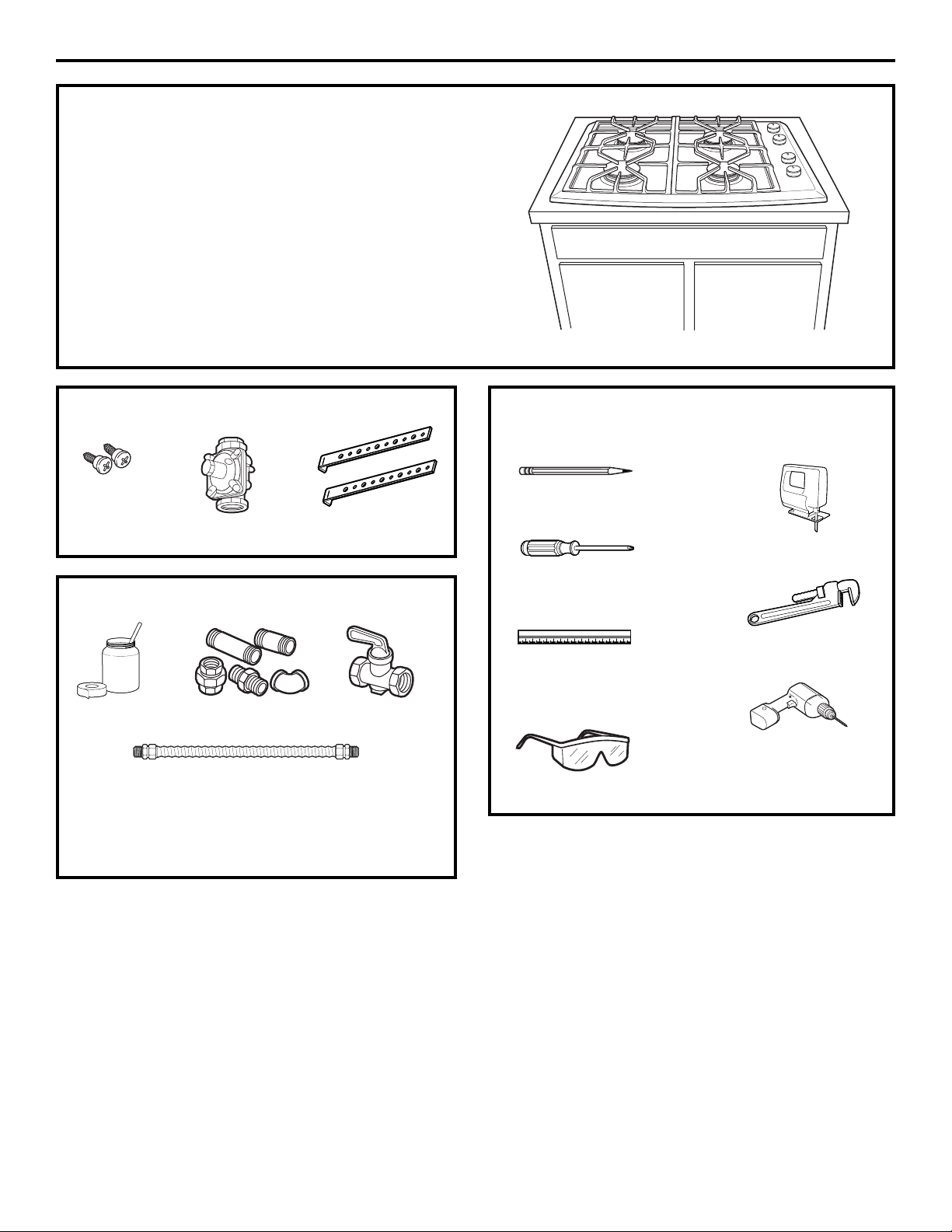
PARTS INCLUDED TOOLS YOU WILL NEED
FOR INSTALLATION
MODELS AVAILABLE
ZGU384N
30″ natural gas cooktop
ZGU384L
30″ LP gas cooktop
These models are factory set for either natural
gas or LP gas operation. Be sure to order the
correct model for the installation situation.
Saber Saw
Pencil
Safety Glasses
1/8″ Drill Bit &
Electric or Hand
Drill
Ruler or
Straightedge
Phillips Head
Screwdriver
Pipe Wrench
MATERIALS YOU MAY NEED
2 Hold
Down Brackets
Shut Off
Valve
Pipe Fittings
CSA-Approved Flexible Gas Line
1/2
″ Min. ID, 1/2″ NPT Connection,
3-foot Maximum Length (Massachusetts Only)
NOTE: Purchase new line, do not use
previously used flexible gas line.
Joint
Sealant
Regulator
2 Screws
Installation Preparation
4
Page 5

ADVANCE PLANNING
• Refer to “Installation Preparation” for
information on appropriate placement and
necessary clearances when planning
installation.
• Avoid placing cabinetry directly above cooktop
when possible.
• If cabinetry is used above cooking surface:
– Use cabinets no more than 13″ deep.
– Maintain 30″ minimum clearance between
cooktop and unprotected cabinets directly
above cooktop.
– If clearance is less than 30″, protect cabinet
bottoms with flame-retardant millboard at
least 1/4″ thick, or gypsum board at least
3/16″ thick, covered with 28 gauge sheet
steel or .02″ thick copper.
– Clearance between cooktop and protected
cabinetry must not be less than 24″.
– An exhaust hood that projects at least 5″
beyond front of cabinets can reduce risk
of burns caused by reaching over heated
surface units.
– Working areas adjacent to the cooktop
should have 18″ minimum clearance between
countertop and cabinet bottom.
•A 30″ or wider exhaust hood with 350 CFM or
greater airflow rating is recommended for use
over this Monogram cooktop.
• Installation must conform with local codes.
In the absence of local codes, the gas cooktop
must comply with the National Fuel Gas Code,
ANSI Z223.1, latest edition.
• Gas supply should be located near the opening
for this cooktop (see Preparing the Opening and
Gas Connection sections of this manual). The
supply should provide natural gas at 7″ of water
column pressure (11″ of water column for LP
gas) and a maximum of 14″ of water column
for natural or LP gas.
• The electric spark ignition feature for this
model requires a 120V electrical power supply
be located in the immediate vicinity of this
cooktop (see Electrical Connections section
of this manual).
WB28T10185 High Altitude Kit
For operation above 5,000 feet, order
WB28T10185 Conversion Kit . This kit includes
orifices for both LP and Natural gas operation.
Installation Preparation
5
INSTALLATION OPTIONS
Cooktop and ZVB30 Downdraft Vent Combination
Installation
These cooktops may be installed with a 30″
Monogram Downdraft Vent, model ZVB30.
See page 12 for cutout and clearances.
– The countertop must have a deep flat surface to
accommodate the combined installation of the
cooktop and vent.
– The downdraft vent with blower, motor and
ductwork will occupy the base cabinet .
– Consideration must be given to electrical and gas
supply locations. See page 8.
Cooktop and ZTD910 or ZKD910 Warming Drawer
Combination Installation
These cooktops may be installed over a Monogram
30″ or 27″ Warming Drawer, model ZTD910 or
ZKD910. See page 13 for cutout and clearances.
– Consideration must be given to electrical and gas
supply locations. See page 8.
Cooktop and ZET1, ZEK938 or ZET938 Single Oven
Combination Installation
These cooktops may be installed over a Monogram
27″ or 30″ Oven, model ZET1, ZEK938 or ZET938.
See page 14 for cutout and clearances.
– Consideration must be given to electrical and gas
supply locations. See page 8.
Installation Above Cabinet Drawers
• When installing the cooktop above a base
cabinet with drawers, it may be necessary to
use a shorter depth (front to back) drawer to
allow clearance for the gas connection.
Page 6
PRE-INSTALLATION CHECKLIST
1. When preparing cooktop opening, make sure
the inside of the cabinet and the cooktop do
not interfere with each other. (See section on
preparing the opening.)
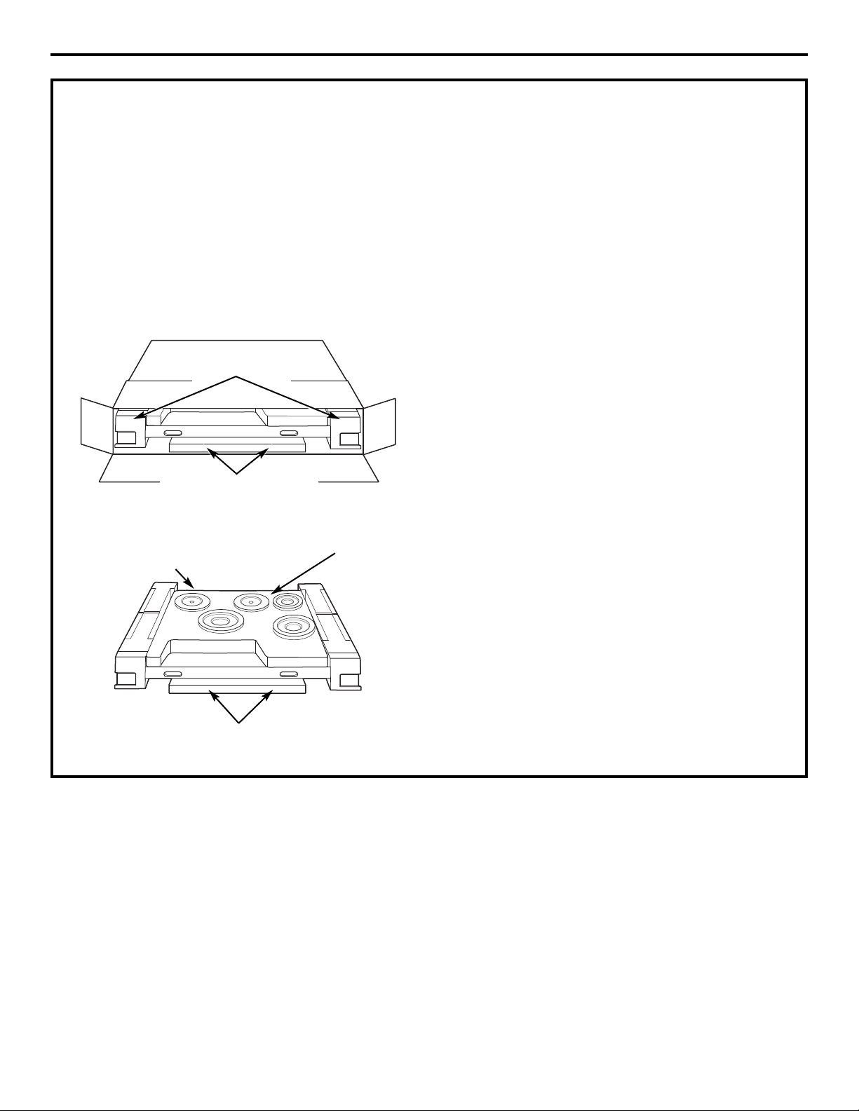
2. Slide the cooktop out of the end of the box.
Remove packaging materials, grate boxes,
regulator and literature package from the
cooktop before beginning installation.
• Use the shipping carton as a pad to protect
customer countertops or flooring.
3. Remove Installation Instructions from literature
package and read them carefully before you
begin.
Be sure to place all literature, Owner’s Manual,
Installations, etc. in a safe place for future
reference.
4. Make sure you have all the tools and materials
you need before starting the installation of the
cooktop.
5. Your home must provide the adequate electrical
service needed to safely and properly use your
cooktop. (Refer to section on electrical
requirements.)
6. When installing your cooktop in your home, make
sure all local codes and ordinances are followed
exactly as stated.
7. Make sure the wall coverings, countertop and
cabinets around the cooktop can withstand heat
(up to 200°F) generated by the cooktop.
Foam support
Packaging containing
left and right side grates
Packaging containing
left and right side grates
Installation Preparation
6
Foam packaging
Regulator taped
to the underside
Page 7
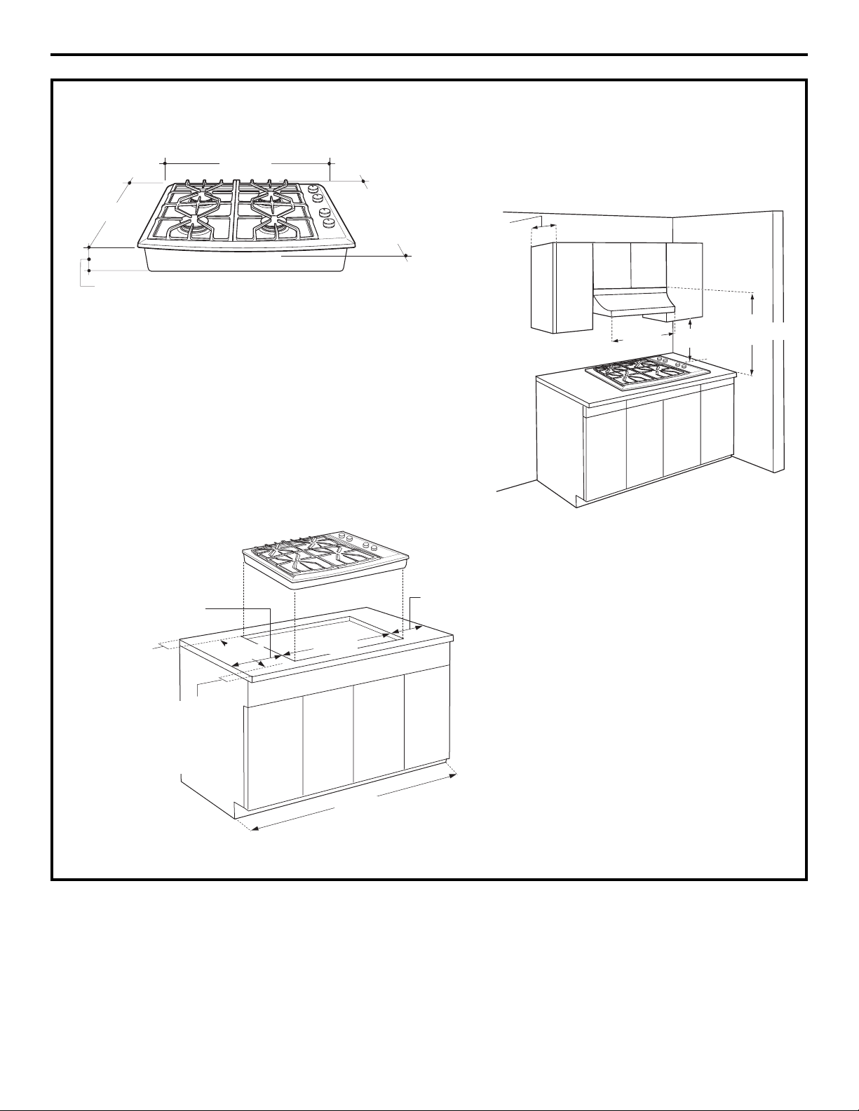
DIMENSIONS AND CLEARANCES
1. Overall cooktop dimensions:
2. Use a 30″ or wider base cabinet.
• Cut the opening in the countertop. To ensure
accuracy, it is best to make a template for the
opening. Make sure the sides of the opening are
parallel and the rear and front cuts are exactly
perpendicular to the sides.
• Observe all minimum clearances.
3. Make sure the wall coverings, countertop and
cabinets around the cooktop can withstand heat
(up to 200°F) generated by the cooktop.
3-3/4″
30-3/4″
21-5/8″
deep at
center
Installation Preparation
7
12″ min.
from cutout
to side wall
2-1/2″ min.
from cutout
to front of
countertop
2-7/8″ min.
from cutout
to rear vertical
combustibles
12″ min.
from cutout
to side wall
28-1/2″
30″ or wider
cabinet base
recommended
19-5/8″
30″ min.
13″ max.
30″
min.
18″ min.
21″
Page 8

POWER SUPPLY LOCATIONS
Gas supply:
These cooktops are shipped from the factory set
for either natural gas or LP gas. Check to be sure
you have the correct cooktop for the type of gas
being used.
• The pressure regulator must be connected in series
with the manifold of the cooktop and must remain
in series with the supply line regardless of type of
gas being used.
• The natural gas model is designed to operate at
5″ water column pressure. A regulator is required
at the natural gas source to provide a minimum
of 6″ water column to the cooktop regulator.
• The liquid propane model is designed to operate at
10″ water column pressure. A regulator is required
at the LP source to provide a minimum of 11″ water
column to the cooktop regulator.
• Maximum inlet pressure for the regulator supplied
with the cooktop is 14″ water column regardless of
the gas being used.
For ease of installation, and if local codes permit,
the gas supply line into the cooktop should be 1/2″
or 3/4″ ID flexible metal appliance connector, three
to five feet long.
NOTE: Purchase new flexible line. DO NOT USE OLD,
PREVIOUSLY USED FLEXIBLE LINE.
• Make gas connection through rear wall, or on
cabinet floor at rear, as illustrated.
1. Install the house gas supply at least 1″ from
the back wall.
2. Locate the electrical outlet 12″ below the
countertop.
Rear–Burner Box
The gas inlet is
located on the
bottom of the
burner box, at
the right rear.
Install a manual shut-off valve in the gas line in an
easily accessible location outside the cooktop. Be
sure you know how and where to shut off the gas
supply to the cooktop. Install the electrical outlet
12″ below the countertop.
Electrical supply:
This cooktop features pilotless electric ignition for
energy savings and reliability. It operates on a 120 volt ,
60 Hz power supply. A separate circuit, protected by a
15 amp time delay fuse or circuit breaker, is required.
• A properly-grounded 3-prong receptacle should
be located within reach of the cooktop’s four-foot
power cord.
IMPORTANT: (Please read carefully). FOR PERSONAL
SAFETY, THIS APPLIANCE MUST BE PROPERLY
GROUNDED.
• The power cord of this appliance is equipped with
a three-prong (grounding) plug which mates with a
standard three-prong grounding wall receptacle to
minimize the possibility of electric shock hazard
from this appliance.
• The customer should have the wall receptacle and
circuit checked by a qualified electrician to make sure
the receptacle is properly grounded and has correct
polarity.
• Where a standard two-prong wall receptacle is
encountered, it is the personal responsibility and
obligation of the customer to have it replaced with
a properly grounded three-prong wall receptacle.
Do Not, Under Any Circumstances, Cut Or Remove
The Third (Ground) Prong From The Power Cord.
Do not use an extension cord.
Installation Preparation
8
Optional Combination Installations
This cooktop may be installed in combination
with a ZVB30 Monogram Downdraft Vent, a ZET1,
ZEK938 or ZET938 Single Oven or a ZTD910 or
ZKD910 Warming Drawer.
• The gas and electrical supply must be located
where it will not interfere with vent housing, the
oven or the warming drawer. Review pages 12
to 14 for additional installation requirements.
1”
min.
12”
Gas
supply
line
1-5/8”
2”
Gas Inlet
Page 9
Installation Instructions
9
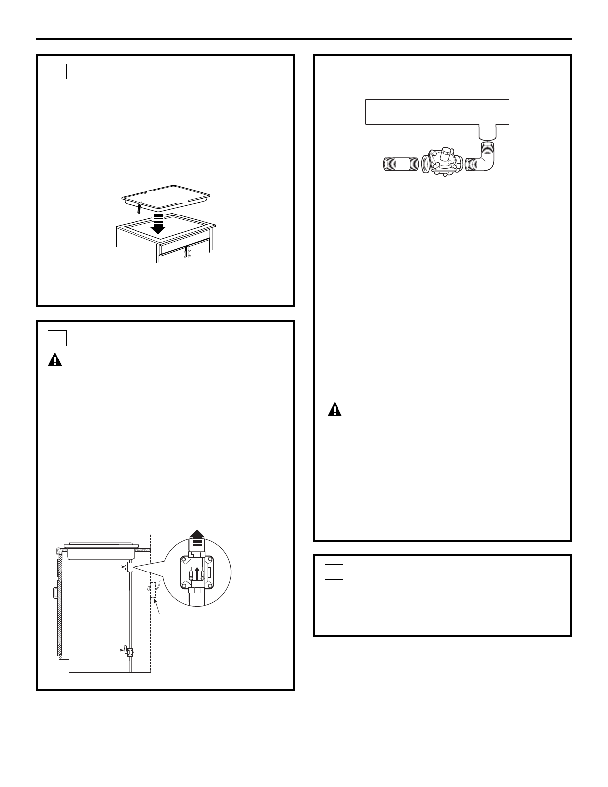
INSTALL THE COOKTOP
A. Remove the screws on the sides of the cooktop
burner box. Use those screws to attach the side
mounting brackets.
B. Insert the cooktop centered into the cutout
opening. Make sure the front edge of the
countertop is parallel to the cooktop.
Check clearances at the front, back and sides.
Secure the hold-down bracket to the cabinet
sides with screws.
1
Cooktop
INSTALL PRESSURE REGULATOR
WARNING: Never reuse old flexible
connectors. The use of old flexible connectors can
cause gas leaks and personal injury. Always use
new flexible connectors when installing a gas
appliance.
To reduce the possibility of gas leaks, apply teflon
tape or a thread compound approved for use with
LP or Natural gases to all threaded connections.
A. Screw the regulator onto the burner box
bottom pipe connection. Make sure the top of
the regulator is facing toward the cabinet front,
and the arrow on the back of the regulator
points to the cooktop.
2
Pressure
regulator
Shut-off
valve
Electrical outlet 12″
below countertop
To cooktop
Rear view
of regulator
(note
direction
of arrow)
INSTALL PRESSURE REGULATOR
(cont.)
OPTION: You can install a 90º elbow (not supplied)
onto the gas inlet and route the gas connections to
avoid interference when installed over an oven,
with a downdraft vent, a warming drawer or other
cabinetry features.
B. Complete the connection between the regulator
and the shut-off valve.
C. Before testing for leaks, make sure all burner
knobs are in the OFF position.
After connecting the cooktop to gas, check
system for leaks with a manometer. If a manometer
is not available, turn the gas supply on to the
cooktop and use a liquid leak detector at all
joints and connections to check for leaks.
Tighten all connections if necessary to prevent gas
leakage in the cooktop or supply line.
WARNING:Do not use a flame to
check for leaks.
Disconnect the cooktop and its individual shut-off
valve from the gas supply piping system during any
pressure testing of that system at test pressures
greater than 1/2 psig (3.5 kPa).
Isolate the cooktop from the gas supply piping
system by closing its individual shut-off valve during
any pressure testing of the gas supply system at
test pressures equal to or less than 1/2 psig (3.5 kPa
).
2
CONNECT ELECTRICAL
• Check to be sure the receptacle is properly
grounded.
• Plug in the power cord.
3
Burner Box
90ºElbow
Page 10
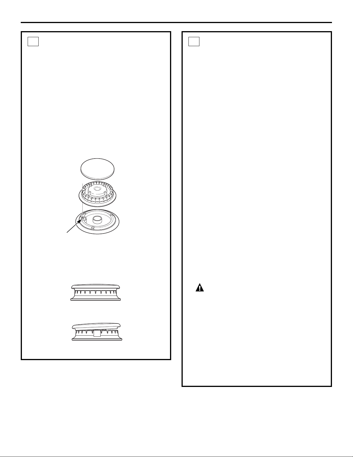
ASSEMBLE BURNERS,
CHECK IGNITION
The electrode of the electronic ignition system
is positioned above the surface of the burner
base. Do not remove a burner cap or touch the
electrode of a burner while another is turned
on. Damage or electrical shock may occur.
A.Remove tape holding burners in position. Note
the position of one larger burner base, head and
cap. The large and regular size pieces are not
interchangeable.
B. Place burner heads over the burner base.
Make sure the hole in the burner head is properly
aligned with the electrode in the burner base.
C. Place the burner caps on the burner heads.
Make sure that the burner caps are properly
seated on the burner heads.
4
Burner cap not properly seated
Burner cap properly seated
Installation Instructions
10
Burner cap
Burner head
assembly
Burner
base
Electrode
ASSEMBLE BURNERS,
CHECK IGNITION (cont.)
D. Check igniters.
Operation of the electric igniters should
be tested after the cooktop and supply line
have been carefully checked for leaks and the
cooktop has been connected to the electrical
power.
• Push and turn a burner valve to the LITE
position. All spark igniters will make a series
of sparks (ticking sounds), but only the burner
turned to LITE will light.
– The burner should light when gas is available
to the burner.
– Once the burner lights, it should be turned to
another position.
• Test each valve separately until all burners have
been checked.
IMPORTANT: If the igniter electrodes continue to
spark after all of the burners are lit, check that
each burner component is assembled and
properly seated.
E. Burner ignition.
Cooktop Spark Ignition—When you turn the
cooktop knob to LITE, the spark igniter makes
a series of electric sparks (ticking sounds) which
light the burner. During a power failure, the
burners will not light automatically. In an
emergency, a cooktop burner may be lit
with a match by following the steps below.
WARNING:Lighting gas burners with
a match is dangerous. You should match light
the cooktop burners only in an emergency.
• Light a match and hold the flame near the
burner you want to light. Wooden matches
work best.
• Push in and turn the control knob slowly.
Be sure you are turning the correct knob
for the burner you are lighting.
NOTE: If the burner does not light within five
seconds, turn the knob off and wait one minute
before trying again.
4
Page 11

Installation Instructions
11
ASSEMBLE BURNERS,
CHECK IGNITION (cont.)
F. Turn on each burner. On LP models, flames
should be blue in color but may have yellow
tips. Natural gas models should have soft, blue
flames. The burner flames should not flutter or
blow away from the burner. The flame should be
no less than 1/4″ on the lowest setting and no
greater than 1-1/2″ on highest setting.
WARNING:If you attempt to measure
the flame, please use caution. Burns could result.
G. Place the two side grates so that a continuous
“arc” is formed with the center ribs of both grates.
Make sure both grates are stable and level.
4
Burners should be checked frequently
Cooktop burner
1/4″ to
1-1/2″
OPERATION CHECKLIST
1. Make sure all controls are left in the OFF
position.
2. The serial plate for your cooktop is located
on the bottom of the burner box. In addition to
the model and serial numbers, it tells you the
ratings of the burners and the type of fuel and
pressure the cooktop was adjusted for when it
left the factory.
3. When ordering parts, always include the serial
number, model number and a code letter to
ensure proper replacement parts.
4. Check again to be sure all installation
procedures have been completed.
Page 12

COOKTOP INSTALLATION WITH A
30″ MONOGRAM DOWNDRAFT VENT,
MODEL ZVB30
The installation of the downdraft vent with
this cooktop requires careful consideration.
Both the cooktop and the vent must be installed
according to each specific installation instruction.
BASE CABINET REQUIREMENTS
The combined installation will fit in a standard
24″ deep base cabinet . Use a 30″ or wider base
cabinet.
– The vent housing, blower and ductwork will
occupy the base cabinet.
COOKTOP REQUIREMENTS
The countertop must have a deep flat surface to
accommodate the cooktop and vent. Countertops
with a rolled front edge and backsplash will not
provide the flat surface area required.
• Review the illustration to determine the countertop
surface requirements.
– All cutout clearances for this installation must be
observed.
POWER SUPPLY
If local codes permit, the vent and cooktop may
operate from the same 120V, 15 amp duplex outlet.
Locate the gas and electrical supply as shown on
page 8.
22-3/8″
cutout
depth
19-5/8″
cooktop
cutout
depth
2-3/4″
30-3/4″
28-1/2″ vent cutout
1/8″
gap
2-7/8″ min. cooktop
cutout to rear vertical
combustible surface
23-7/8″
total flat
surface
required
at center
12″ min. cutout to
wall, both sides
2-1/2″ min. clearance
to cutout
Front edge of countertop
7/16″ cooktop overlap
(1-1/4″ at center)
Installation Options
12
28-1/2″ cooktop
area cutout
Page 13

Installation Options
13
COOKTOP INSTALLATION OVER A
MONOGRAM WARMING DRAWER,
MODEL ZTD910 OR ZKD910
These cooktops may be installed over a 30″
or 27″ Warming Drawer. Both the cooktop and
the warming drawer must be installed according to
each specific installation instruction.
Use a 30″ or wider base cabinet .
• Plan gas supply location carefully to avoid
interference with the warming drawer.
POWER SUPPLY:
If local codes permit, the cooktop and warming
drawer may operate from the same 120V duplex
outlet. Refer to installation instructions for details.
Install 2x4 or 2x2 anti-tip block against
rear cabinet wall 9″ from cutout floor
to bottom of block
23-1/2″ min.
Cooktop 28-1/2″
19-5/8″
2-1/2″ min.
1-1/2″ cabinet top
5-1/2″ min.
NOTE: When installing a Monogram Warming Drawer
below a cooktop, a solid barrier must be installed at least
1″ from the lowest point of the bottom of cooktop
burner box to the top of cutout. See Warming Drawer
Installation Instructions for details.
36″
countertop
height
9-1/4″
A
25″
9″
Dim. A
ZTD910 28-1/2″
ZKD910 25-1/2″
Page 14

COOKTOP INSTALLATION OVER A
27″ OR 30″ MONOGRAM SINGLE OVEN,
MODEL ZET1, ZEK938 OR ZET938
These cooktops may be installed over the
Monogram ZET1, ZEK938 or ZET938 single oven.
Both the cooktop and the oven must be installed
according to each specific installation instruction.
– Allow 4″ Min. clearance from the top of the
countertop to the top of the oven cutout .
Use a 30″ or wider base cabinet .
• For best appearance, the cooktop should be
centered over the oven.
POWER SUPPLY
The oven requires a separate, properly grounded
20 Amp, 3-wire 208 or 240 volt , 60 Hz power supply.
The cooktop requires a separate 120V power supply.
See page 8. Where codes permit, the gas shut-off
valve may be located in an adjacent cabinet or
other easily accessible location.
Use two 2x4’s or equivalent runners spaced 25″ centerline
to centerline in the opening and flush with top of toekick.
Or elevate the oven floor to desired height. The support must
be level, rigidly mounted and capable of supporting 200 lbs.
23-1/2″ min.
4″ high
toekick
Cooktop
28-1/2″
19-5/8″
2-1/2″ min.
1-1/2″ cabinet top
4″ min.
36″
countertop
height
B
A
25″
C
L
25″
Installation Options
14
C
L
Ovens Dim. A Dim. B
30″ 28-1/2″ min. 27-1/4″ min.
28-5/8″ max. 27-5/16″ max.
27″ 25″ min. 27-5/8″ min.
25-1/4″ max. 28-1/8″ max.
Page 15

15
ADJUST THE REGULATOR
A. Disconnect all electrical power, at the main circuit
breaker or fuse box.
B. Shut off the gas supply to the cooktop by closing the
manual shut-off valve.
C. Adjust the pressure regulator by the following
instructions:
• Unscrew the cap.
• Place your thumb against the flat side of the spring
retainer and press down to remove the retainer.
• Carefully look at the spring retainer to locate the NAT
or LP position.
• Turn the spring retainer over so that the desired gas is
showing on the bottom.
• Snap the retainer back into position.
• Screw the cap back onto the regulator.
1
CHANGE BURNER ORIFICES
INSTALLATION TIP: First remove all
orifices and then start replacing them.
This will help to prevent the possibility
that some may not be replaced.
A. Remove the burner grates,
burner caps and burner heads.
B. Using a 7mm nut driver, remove the
top burner orifices. There are two
orifices per burner.
The main orifice is
located low in the center
of the burner, while the
simmer orifice is located
higher beside the center
of the burner.
2
Gasket
Cap
Spring
retainer
L.P./propane
position
NAT.
position
Pressure regulator
Burner cap
Burner
head
Burner
base
Spark igniter
Main
orifice
Simmer
orifice
SAFETY INFORMATION
The pressure regulator and burner orifices are set for
natural gas operation.
To convert this cooktop from natural gas operation to
LP operation, the regulator and burner orifices must be
converted. LP burner orifices are attached to the regulator.
CAUTION — The cooktop, as shipped from the
factory, is set for use with its intended gas. If you wish
to use your cooktop with the alternate gas, you must
first replace the orifices and convert the pressure
regulator.
WARNING — This conversion must be
performed by a qualified installer or gas supplier in
accordance with the manufacturer’s instructions and
all codes and requirements of the authority having
jurisdiction. Failure to follow instructions could result in
serious injury or property damage. The qualified agency
performing this work assumes responsibility for the
conversion.
CAUTION — The following adjustments must
be made before turning on the burner. Failure to do so
could result in serious injury. Be sure pressure regulator
has been converted as described in Step 1.
TOOLS YOU WILL NEED FOR
CONVERSION
Safety glasses
Small flat-head
screwdriver
(2 to 2.4 mm or
3/32″ tip size,
60 mm long)
Crescent wrench
7mm nutdriver
Installation Convert Natural Gas Model ZGU384NSMSS
Instructions
to LP Gas Operation
LP
NAT
LP
NAT
NAT
LP
NAT
LP
FOR OFF
DOWN
Page 16

ADJUST BURNER FLAMES
A. Turn all burners on highest setting and check the flames.
They should be blue in color and may have some yellow
tipping at the ends of the flame when using LP gas.
Foreign particles in the gas line may cause an orange
flame at first, but this will soon disappear.
B. Turn the cooktop burner knob to “LO” while observing
the flame.
Adjust the setting of the upper row of flames using the
valve bypass screw as follows:
Adjustments must be made with two other burners in
operation on a medium setting. This prevents the upper row
of flames from being set too low, resulting in the flame
being extinguished when other burners are turned on.
C. To adjust the flame, remove the knobs. Insert a screwdriver
through the access hole in valve shaft as shown.
• If the flames were too small or fluttered, open the valve
more than the original setting.
• If the flames blew away from the burner, close the valve
more than the original setting.
D. Make the adjustment by slowly turning the screw until
flame appearance is correct.
E. Testing Flame Stability:
Test 1 – Turn the knob from “HI” to “LO” quickly.
If the upper row of flames goes out at this setting,
increase the flame size and test again.
Test 2 – With the burner on “LO”, open and close the
cabinet door under the cooktop. If the flame is
extinguished by the air currents created by the
door movement, increase the flame height and
test again.
NOTE: When the burner is on the “SIM” setting, the upper
row of flames will go out.
F. Flame Recheck:
After the adjustment is made, turn all burners off. Ignite
each burner individually. Observe the flame at the “HI”
position. Rotate the knob to the lowest setting and be
sure that the flame size decreases as the knob is
rotated counterclockwise.
Once the conversion is complete and checked ok,
fill out the conversion sticker and include your name,
organization and date conversion was made. Apply
the sticker near the cooktop gas inlet opening to
alert others in the future that this appliance has been
converted. If converting back to the original gas, please
remove the sticker so others know the appliance is set
to use its original gas.
3
CHANGE BURNER ORIFICES (cont.)
IMPORTANT: Orifices must be located exactly as shown.
Carefully read and observe each orifice label for correct
location.
C. Install the proper orifices in the exact locations as noted
in the illustrations above.
D. Return the natural gas orifices to the bracket and
reattach the bracket and the instruction sheet to the
pressure regulator using the screw removed previously.
E. Replace the burner bases, heads, caps and top grates.
2
SIMMER
ORIFICES
Installation Instructions for Natural to LP Gas Conversion
16
MAIN
ORIFICES
The 34SL and
51SN are for all
four burners.
Page 17

17
Installation Convert LP Gas Model ZGU384LSMSS
Instructions
to Natural Gas Operation
ADJUST THE REGULATOR
A. Disconnect all electrical power, at the main circuit
breaker or fuse box.
B. Shut off the gas supply to the cooktop by closing the
manual shut-off valve.
C. Adjust the pressure regulator by the following
instructions:
• Unscrew the cap.
• Place your thumb against the flat side of the spring
retainer and press down to remove the retainer.
• Carefully look at the spring retainer to locate the NAT
or LP position.
• Turn the spring retainer over so that the desired gas is
showing on the bottom.
• Snap the retainer back into position.
• Screw the cap back onto the regulator.
1
CHANGE BURNER ORIFICES
INSTALLATION TIP: First remove all
orifices and then start replacing them.
This will help to prevent the possibility
that some may not be replaced.
A. Remove the burner grates,
burner caps and burner heads.
B. Using a 7mm nut driver, remove the
top burner orifices. There are two
orifices per burner.
The main orifice is
located low in the center
of the burner, while the
simmer orifice is located
higher beside the center
of the burner.
2
Gasket
Cap
Spring
retainer
L.P./propane
position
NAT.
position
Pressure regulator
Burner cap
Burner
head
Burner
base
Spark igniter
Main
orifice
Simmer
orifice
SAFETY INFORMATION
The pressure regulator and burner orifices are set for
Liquid Propane (LP) gas operation.
To convert this cooktop from LP gas operation to
natural gas operation, the regulator and burner orifices
must be converted. Natural gas burner orifices are
attached to the regulator.
CAUTION — The cooktop, as shipped from the
factory, is set for use with its intended gas. If you wish
to use your cooktop with the alternate gas, you must
first replace the orifices and convert the pressure
regulator.
WARNING — This conversion must be
performed by a qualified installer or gas supplier in
accordance with the manufacturer’s instructions and
all codes and requirements of the authority having
jurisdiction. Failure to follow instructions could result in
serious injury or property damage. The qualified agency
performing this work assumes responsibility for the
conversion.
CAUTION — The following adjustments must
be made before turning on the burner. Failure to do so
could result in serious injury. Be sure pressure regulator
has been converted as described in Step 1.
TOOLS YOU WILL NEED FOR
CONVERSION
Safety glasses
Small flat-head
screwdriver
(2 to 2.4 mm or
3/32″ tip size,
60 mm long)
Crescent wrench
7mm nutdriver
LP
NAT
LP
NAT
NAT
LP
NAT
LP
FOR OFF
DOWN
Page 18

18
ADJUST BURNER FLAMES
A. Turn all burners on highest setting and check the flames.
They should be blue (no yellow tipping) when using
natural gas. Foreign particles in the gas line may cause
an orange flame at first, but this will soon disappear.
B. Turn the cooktop burner knob to “LO” while observing
the flame.
Adjust the setting of the upper row of flames using the
valve bypass screw as follows:
Adjustments must be made with two other burners in
operation on a medium setting. This prevents the upper row
of flames from being set too low, resulting in the flame
being extinguished when other burners are turned on.
C. To adjust the flame, remove the knobs. Insert a screwdriver
through the access hole in valve shaft as shown.
• If the flames were too small or fluttered, open the valve
more than the original setting.
• If the flames blew away from the burner, close the valve
more than the original setting.
D. Make the adjustment by slowly turning the screw until
flame appearance is correct.
E. Testing Flame Stability:
Test 1 – Turn the knob from “HI” to “LO” quickly.
If the upper row of flames goes out at this setting,
increase the flame size and test again.
Test 2 – With the burner on “LO”, open and close the
cabinet door under the cooktop. If the flame is
extinguished by the air currents created by the
door movement, increase the flame height and
test again.
NOTE: When the burner is on the “SIM” setting, the upper
row of flames will go out.
F. Flame Recheck:
After the adjustment is made, turn all burners off. Ignite
each burner individually. Observe the flame at the “HI”
position. Rotate the knob to the lowest setting and be
sure that the flame size decreases as the knob is
rotated counterclockwise.
Once the conversion is complete and checked ok,
fill out the conversion sticker and include your name,
organization and date conversion was made. Apply
the sticker near the cooktop gas inlet opening to
alert others in the future that this appliance has been
converted. If converting back to the original gas, please
remove the sticker so others know the appliance is set
to use its original gas.
3
CHANGE BURNER ORIFICES (cont.)
IMPORTANT: Orifices must be located exactly as shown.
Carefully read and observe each orifice label for correct
location.
C. Install the proper orifices in the exact locations as noted
in the illustrations above.
D. Return the LP gas orifices to the bracket and reattach
the bracket and the instruction sheet to the pressure
regulator using the screw removed previously.
E. Replace the burner bases, heads, caps and top grates.
2
SIMMER
ORIFICES
MAIN
ORIFICES
Installation Instructions for LP to Natural Gas Conversion
The 34SL and
51SN are for all
four burners.
Page 19

La section Française
19
AVANT DE COMMENCER
Avant de commencer, lisez attentivement la
totalité de ces instructions.
•
IMPORTANT — Conservez ces
instructions pour votre inspecteur local.
•
IMPORTANT — Respectez toutes les
ordonnances et les codes locaux.
• Note à l’installateur – Assurez-vous de laissez
ces instructions au consommateur.
• Note au consommateur – Conservez ces
instructions pour référence future.
• La garantie ne couvre aucune panne due à une
mauvaise installation.
AVERTISSEMENT —
Cet appareil doit être bien mis à la terre.
•
IMPORTANT — Vous devez vérifier que
cet appareil n’ait pas de fuite conformément aux
instructions du fabricant.
• L’installateur est responsable d’une bonne
installation et la garantie ne couvre aucune
panne due à une mauvaise installation.
POUR VOTRE SÉCURITÉ
AVERTISSEMENT —
Si vous ne suivez pas exactement les instructions
de ce manuel, vous risquez d’occasionner un
incendie, une explosion ou une fuite de gaz, qui
peuvent provoquer des dommages matériels,
des blessures corporelles ou la mort.
Ne conservez pas ou n'utilisez jamais
d'essence ou d'autres liquides ou vapeurs
inflammables à proximité de cet appareil
ou de tout autre appareil ménager!
CI QUE VOUS DEVEZ FAIRE SI
VOUSSENTEZ LE GAZ:
• N’essayez jamais d’allumer un appareil
électroménager. Ne touchez à aucun
commutateur d’électricité, n’utilisez jamais
un téléphone dans votre bâtiment.
• Appelez immédiatement votre fournisseur de
gaz à l’aide du téléphone d’un voisin. Suivez les
instructions de votre fournisseur de gaz.
• Si vous ne pouvez pas entrer en contact avec
votre fournisseur de gaz, appelez les pompiers.
L’installation et le service de votre table de cuisson
doivent être faits par un installateur qualifié, un
technicien de service ou votre fournisseur de gaz.
Information de la sécurité
Page 20

Information de la sécurité
20
AVERTISSEMENT — Débranchez
tout courant électrique au niveau du disjoncteur de
la maison ou de la boîte à fusibles avant d’installer.
La conception de votre table de cuisson a été
approuvé par Underwriters Laboratories. Vous
trouverez des précautions à prendre en matière de
sécurité dans votre Guide d’utilisation et de soins.
Lisez-les attentivement.
• L’installation de votre table de cuisson doit se
conformer aux codes locaux ou, en l’absence de
codes locaux, au National Fuel Gas Code, ANSI
Z223.1/NFPA 54 Dernière édition.
• Assurez-vous que votre table de cuisson soit bien
installée par un installateur qualifié ou un
technicien de service.
• Pour éliminer tout mouvement corporel au dessus
des brûleurs de votre table de cuisson, évitez de
placer des armoires de cuisine au dessus des
brûleurs.
• N’installez jamais votre appareil près d’une porte
d’entrée ou dans un emplacement où un courant
d’air peut gêner son usage.
BESOINS D’ÉLECTRICITÉ
Cet appareil ménager doit être livré avec le bon
voltage et la bonne fréquence et branché à son
propre circuit de dérivation bien mis à la terre,
protégé par un disjoncteur ou un fusible qui ont
l’ampérage noté sur la plaque minéralogique de
votre appareil.
Nous vous recommandons de faire brancher le
câblage électrique et la fiche de votre cuisinière par
un électricien qualifié. Après l’installation,
demandez à l’électricien de vous montrer
l’emplacement de votre coupe-circuit principal.
Demandez à votre entreprise de services publics les
codes électriques en vigueur dans votre région. En
ne câblant pas votre cuisinière conformément aux
codes en vigueur, vous provoquez une situation
dangereuse. En l’absence de codes, vous devez
câbler et isoler votre cuisinière conformément
aux exigences du Canadian Electrical Code.
CONTENU
Préparation à l’installation
Modèles disponibles . . . . . . . . . . . . . . . . . . . .21
Pièces comprises . . . . . . . . . . . . . . . . . . . . . . . 21
Matériaux dont vous pourriez
avoir besoin . . . . . . . . . . . . . . . . . . . . . . . . . . . . 21
Outils dont vous aurez besoin . . . . . . . . . . 21
Options d'installation et de planification . 22
Liste de vérification de pré-installation . . 23
Dimensions et dégagements . . . . . . . . . . . 24
Emplacements de l'alimentation de gaz . 25
Instructions d’installation
Instructions étape par étape . . . . . . . . 26–28
Liste de vérification de fonctionnement . . 28
Choix d’installation
Installation avec un évent descendant . . 29
Installation sur un tiroir
chauffe-aliments . . . . . . . . . . . . . . . . . . . . . . 30
Installation sur un four simple . . . . . . . . . . 31
Instructions d'installation pour la conversion du gaz naturel au gaz PL
Outils dont vous aurez besoin . . . . . . . . . . 32
Ajuster le régulateur . . . . . . . . . . . . . . . . . . . 32
Changer les orifices . . . . . . . . . . . . . . . . 32, 33
Ajuster les flammes du brûleur . . . . . . . . . 33
Instructions d’installation pour la conversion du gaz PL au gaz naturel
Outils dont vous aurez besoin . . . . . . . . . . . 34
Ajuster le régulateur . . . . . . . . . . . . . . . . . . . 34
Changer les orifices . . . . . . . . . . . . . . . . . 34, 35
Ajuster les flammes du brûleur . . . . . . . . . . 35
Page 21

21
PIÈCES COMPRISES OUTILS DONT VOUS AUREZ BESOIN
POUR L’INSTALLATION
MODÈLES DISPONIBLES
ZGU384N
Surface de cuisson au gaz naturel de 76 cm (30 po)
ZGU384L
Surface de cuisson au gaz PL de 76 cm (30 po)
Ces modèles sont programmés en usine pour
un fonctionnement au gaz naturel ou au gaz PL.
Assurez-vous de commander le modèle adéquat
à votre type d'installation.
Scie sauteuse
Crayon
Lunettes
de sécurité
Perceuse à main
et mèche de
1/8 po
Règle ou règle
de vérification
Tournevis à
tête Phillips
Clé à tube
MATÉRIAUX DONT VOUS POURRIEZ
AVOIR BESOIN
2 Supports
de retenue
Clapet de
fermeture
Raccords de tuyau
Conduite flexible de gaz approuvé par la CSA,
min. ID de 1,3 cm (1/2 po), connexion NPT
de 1,3 cm (1/2 po), longueur maximale de
0,9 mètre (3 pi) (Massachusetts seulement)
REMARQUE : achetez un nouveau conduit,
n’utilisez pas de conduite de gaz flexible.
Scellant
à joint
Régulateur
2 Vis
Préparation à l’installation
Page 22

PLANIFICATION AVANCÉE
• Consultez «Préparation de l’installation» pour des
informations sur l’emplacement et les dégagements
adéquats lorsque vous planifiez une installation.
• Autant que possible, évitez de placer les armoires de
cuisine directement au-dessus de la surface de cuisson.
• Si vous avez des armoires au-dessus de la
surface de cuisson :
– Utilisez des armoires de 33 cm (13 po)
de profondeur maximum.
– Maintenez un dégagement d’au moins 76 cm
(30 po) entre la surface de cuisson et les
armoires non protégées directement audessus de la surface de cuisson.
– Si le dégagement est inférieur à 76 cm (30 po),
protégez les dessous d’armoire avec un
celloderme pare-flammes d’au moins 60 mm
(1/4 po) d’épaisseur ou une planche de gypse
d’au moins 47 mm (3/16 po) d’épaisseur,
recouverte d’acier inoxydable de calibre 28
ou de cuivre de 5 mm (0,02 po) d’épaisseur.
– Le dégagement entre la surface de cuisson
et les armoires protégées ne doit pas être
inférieur à 61 cm (24 po).
– Une hotte d'aspiration projetée à un minimum
de 13 cm (5 po) à l’avant des armoires peut réduire
le risque de brûlures causées lorsque l’on tente
de tendre le bras par-dessus les éléments chauffés.
– Les zones de travail adjacentes à la surface
de cuisson doivent présenter un dégagement
minimal de 46 cm (18 po) entre le dessus du
comptoir et le fond des armoires.
• L’utilisation d’une hotte d’aspiration de 76 cm
(30 po) de largeur ou plus avec 350 CFM ou plus
de débit d’air est recommandée avec cette
surface de cuisson Monogram.
• L’installation doit être conforme aux codes
locaux. En l’absence de codes locaux, la surface
de cuisson doit se conformer au code du
National Fuel Gas, ANSI Z223.1, dernière édition.
• L’alimentation en gaz doit se trouver près
de l’ouverture de cette surface de cuisson
(consultez les sections «Préparation de
l’ouverture» et «Connexion de gaz» de ce
manuel). L’alimentation doit vous fournir du gaz
naturel à 18 cm (7 po) de la colonne d’eau
28 cm (11 po) de la colonne d’eau pour le gaz PL
et à un maximum de 35,3 cm (14 po) de la
colonne d’eau pour le gaz naturel ou PL.
• L’option d’allumage électrique pour ce modèle
requiert une alimentation électrique de 120V
située dans les environs immédiats de cette
surface de cuisson (consultez la section
«Connexions électriques» de ce manuel).
Kit de conversion haute altitude WB28T10185
Pour l’opération >1 524 m (>5 000 pi), commandez
le kit de conversion WB28T10185. Ce kit comprend
les orifices pour l’opération du GPL et du gaz naturel.
Préparation à l’installation
22
OPTIONS D’INSTALLATION
Installation de la surface de cuisson et de la
combinaison ZVB30 à évent descendant
Ces surfaces de cuisson peuvent être installées
avec l’évent descendant Monogram de 76 cm
(30 po), modèle ZVB30. Consultez la page 29
pour les découpes et les dégagements.
– Le comptoir doit présenter une surface plate pour
loger l’installation combinée surface de cuisson
et évent.
– L’évent descendant avec ventilateur, moteur
et conduits occupera l’armoire de base.
– Prenez soin d’envisager les emplacements de
l’électricité et du gaz. Consultez la page 25.
Installation de la combinaison surface de cuisson et
tiroir chauffe-aliments de modèle ZTD910 ou ZKD910
Ces surfaces de cuisson peuvent être installées sur
un tiroir chauffe-aliments de 76 cm ou de 68,5 cm
(30 po ou 27 po) de Monogram, modèle ZTD910 ou
ZKD910. Consultez la page 30 pour les découpes
et dégagements.
– Prenez soin d’envisager les emplacements de
l’électricité et du gaz. Consultez la page 25.
Installation de la combinaison four simple ZET1,
ZEK938 ou ZET938
Ces surfaces de cuisson peuvent être installées
sur un four 76 cm (30 po) ou 68,6 cm (27 po) de
Monogram, modèle ZET1, ZEK938 ou ZET938.
Consultez la page 31 pour les découpes et les
dégagements.
– Prenez soin d'envisager les emplacements de
l’électricité et du gaz. Consultez la page 25.
Installation au-dessus des tiroirs des armoires
• Lorsque vous installez la surface de cuisson
au-dessus d’armoires de base avec tiroirs, il peut
être nécessaire d’utiliser un tiroir de profondeur
moindre (avant ou arrière) pour permettre le
dégagement nécessaire à la connexion de gaz.
Page 23

LISTE DE VÉRIFICATION DE PRÉ-INSTALLATION
1. Lorsque vous préparez l’ouverture de la surface
de cuisson, assurez-vous que l’intérieur de
l’armoire et la surface de cuisson ne se nuisent
pas. (Consultez la section «Préparation de
l’ouverture»).
2. Glissez la surface de cuisson hors de la boîte.
Retirez les matériaux d’emballage, les boîtes de
grilles, le régulateur et la documentation avant
de débuter l’installation.
• Utilisez le carton d’expédition comme coussinet
de protection pour les comptoirs ou le revêtement
de plancher.
3. Sortez les instructions d’installation du paquet de
la documentation et lisez-les attentivement avant
de commencer.
Assurez-vous de placer toute la documentation,
le manuel du propriétaire, les instructions
d’installation etc. dans un endroit sûr pour
référence future.
4. Assurez-vous d’avoir en main tous les outils
et matériaux nécessaires avant de débuter
l’installation de la surface de cuisson.
5. Votre domicile doit être doté d’une alimentation
électrique adéquate pour une utilisation sûre
et appropriée de votre surface de cuisson.
(Consultez la section «Exigences électriques»).
6. Lorsque vous installez votre surface de cuisson
à domicile, assurez-vous de vous conformer
à tous les codes et règlements locaux.
7. Assurez-vous que les revêtements muraux,
les comptoirs et les armoires autour de la surface
de cuisson peuvent supporter la chaleur (jusqu’à
93 °C ou 200 °F) générée par la surface de cuisson.
Support en mousse
Emballage avec les grilles
des côtés gauche et droit
Emballage avec les grilles
des côtés gauche et droit
Préparation à l’installation
23
Emballage mousse
Le régulateur est collé
sur la face antérieure
Page 24

DIMENSIONS ET DÉGAGEMENTS
1. Dimensions globales de la surface de cuisson :
2. Utilisez une armoire de base de 76,2 cm (30 po)
de largeur ou plus.
• Découpez l’ouverture dans le comptoir. Pour
assurer l’exactitude, il est indiqué de faire un
gabarit d’ouverture. Assurez-vous que les côtés
de l’ouverture sont parallèles et que les découpes
avant et arrière sont exactement perpendiculaires
aux côtés.
• Observez tous les dégagements minimums.
3. Assurez-vous que les revêtements muraux,
les comptoirs et les armoires autour de la surface
de cuisson peuvent supporter la chaleur (jusqu’à
93,3 °C ou 200 °F) générée par la surface de
cuisson.
9,5 cm (3-3/4 po)
78 cm (30-3/4 po)
54,9 cm (21-5/8 po)
de profondeur au centre
Préparation à l’installation
24
30,5 cm (12 po) min.
du mur à la découpe
6,4 cm
(2-1/2 po)
min. du
rebord avant
de la
découpe au
rebord avant
du comptoir
7,3 cm
(2-7/8 po)
min. de
dégagement
vers les
combustibles
verticaux
30,5 cm (12 po) min.
du mur à la découpe
72,3 cm
(28-1/2 po)
Base d’armoire
de 76,2 cm (30 po) ou
plus large recommandée
49,8 cm (19-5/8 po)
Min.
76 cm
(30 po)
Max.
33 cm
(13 po)
Min.
76,2 cm
(30 po)
Min. 46 cm
(18 po)
53,3 cm
(21 po)
Page 25

25
EMPLACEMENTS DE L’ALIMENTATION
DE GAZ
Alimentation de gaz :
Ces surfaces de cuisson sont expédiée de l’usine prêtes
à être utilisées avec le gaz naturel ou le gaz PL. Vérifiez
que votre surface de cuisson est celle qui est appropriée
au type de gaz utilisé.
• Le régulateur de pression doit être branché en série
avec le collecteur de la surface de cuisson et doit
demeurer en série avec la conduite d’alimentation,
peu importe le type de gaz utilisé.
• Le modèle au gaz naturel est conçu pour fonctionner à
12,7 cm (5 po) de pression de la colonne d’eau. Un
régulateur est requis à la source de gaz naturel pour
procurer un minimum de 15,2 cm (6 po) de la colonne
d’eau au régulateur de la surface de cuisson.
• Le modèle au gaz propane est conçu pour fonctionner
à 24,5 cm (10 po) de pression de la colonne d’eau. Un
régulateur est requis à la source de gaz PL pour procurer
un minimum de 28 cm (11 po) de la colonne d’eau au
régulateur de la surface de cuisson.
• La pression d’admission maximale pour le régulateur
fourni avec la surface de cuisson est de 35,5 cm (14 po)
de la colonne d’eau, peu importe le type de gaz utilisé.
Pour faciliter l’installation et si les codes locaux le
permettent, la conduite d’alimentation de gaz menant à
la surface de cuisson doit être un connecteur flexible
métallique ID de 1,3 cm (1/2 po) ou 1,7 cm (3/4 po) et de
0,9 à 1,5 mètres (3 à 5 pi) de longueur.
REMARQUE : achetez une nouvelle conduite flexible.
N’UTILISEZ JAMAIS UNE CONDUITE FLEXIBLE USAGÉE.
• Faites la connexion de gaz à travers la paroi arrière
ou sur le plancher de l’armoire à l’arrière, tel qu’illustré.
1. Installez l’alimentation de gaz à la maison à un
minimum de 2,54 cm (1 po) de la paroi arrière.
2. Installez la sortie électrique 30,5 cm (12 po) sous
le comptoir.
Arrière–Enceinte du brûleur
L’admission de gaz
est située au bas
de l’enceinte du
brûleur, dans la
partie droite
arrière.
Installez une soupape de coupure manuelle de la
conduite de gaz en un endroit facilement accessible
à l’extérieur de la surface de cuisson. Assurez-vous que
vous savez comment et où couper l’alimentation de gaz
à la surface de cuisson. Installez la prise électrique à
30,5 cm (12 po) sous le comptoir.
Alimentation électrique :
Cette surface de cuisson offre un allumage électrique
sans veilleuse pour vous procurer économie et fiabilité.
Elle fonctionne sur une alimentation électrique de 120
volts, 60 Hz. Un circuit séparé, protégé par un fusible à
délai d’entrée de 15 ampères ou un disjoncteur, est requis.
• Un réceptacle à trois (3) broches correctement mis
à la terre doit être situé à porté du cordon électrique de
1,2 mètre (4 pi) de la surface de cuisson.
IMPORTANT (lire attentivement) : POUR VOTRE PROPRE
SÉCURITÉ, CET ÉLECTROMÉNAGER DOIT ÊTRE
CORRECTEMENT MIS À LA TERRE.
• Cet appareil est muni d’un cordon d’alimentation doté
d’une fiche triphasée qui se branche sur une prise
murale standard triphasée mise à la terre afin de
minimiser le risque de choc électrique.
• Le client doit faire vérifier la prise murale et le circuit par
un électricien autorisé pour vous assurer que la prise
est correctement mise à la terre et possède la bonne
polarité.
• Si vous avez une prise murale standard à deux fiches,
il vous incombe et de votre obligation de la faire
remplacer par une prise murale triphasée.
En aucun vous ne devez couper et retirer la troisième
broche de mise à la terre du cordon d’alimentation.
N’utilisez pas de rallonge électrique.
Préparation à l’installation
Installations de combinaison en option
Cette surface de cuisson peut être installée en
combinaison avec un évent descendant Monogram
ZVB30 et un four simple ZET1, ZEK938 ou ZET938 ou
avec un tiroir chauffe-aliments ZTD910 ou ZKD910.
• L’alimentation en gaz et en électricité doit être
située à un endroit où elle ne nuit pas au boîtier de
l’évent, au four ou au tiroir chauffe-aliments.
Consultez les pages 29 à 31 pour les autres
exigences d’installation.
Min.
2,5 cm
(1 po)
30,5 cm
(12 po)
L’alimentation
de gaz
4,1 cm
(1-5/8 po)
5,1 cm (2 po)
Admission de gaz
Page 26

Instructions d’installation
26
INSTALLEZ LA SURFACE DE CUISSON
A. Retirez les vis des côtés de la boîte de brûleur
de la surface de cuisson. Utilisez ces vis pour
attacher les supports de fixation latéraux.
B. Insérez la surface de cuisson centrée dans
l’ouverture découpée. Assurez-vous que le rebord
avant du comptoir est parallèle à la surface
de cuisson.
Vérifiez les dégagements à l'arrière, à l’avant
et sur les côtés.
Fixez le support de retenue des côtés
de l’armoire avec des vis.
1
Surface
de cuisson
INSTALLEZ LE RÉGULATEUR
DE PRESSION
AVERTISSEMENT : ne réutilisez
jamais de vieux connecteurs flexibles. Leur utilisation
peut entraîner des fuites de gaz et des blessures.
Utilisez toujours de nouveaux connecteurs flexibles
lorsque vous installez un appareil au gaz.
Pour réduire la possibilité de fuites de gaz, appliquez
un ruban Teflon ou une pâte lubrifiante approuvée
pour une utilisation avec gaz PL ou gaz naturel à
toutes les connexions filetées.
A. Vissez le régulateur sur la connexion du tuyau
inférieur de la boîte de brûleur. Assurez-vous que
le haut du régulateur fait face à l’avant de
l’armoire et que la flèche à l’arrière du régulateur
pointe vers la surface de cuisson.
2
Régulateur
de pression
Soupape
de coupure
Sortie électrique
30,5 cm
(12 po) sous
le comptoir
Vers la surface
de cuisson
Vue
arrière du
régulateur
(notez la
direction de
la fleche)
INSTALLEZ LE RÉGULATEUR
DE PRESSION (suite)
OPTION : Vous pouvez poser un coude 90º (non
fourni) sur l’admission de gaz et acheminer les
raccords de gaz de façon à éviter les obstacles dans
le cas d’installations au-dessus d’un four, ou avec un
évent de contre-tirage, un tiroir chauffe-aliments ou
d’autres accessoires.
B. Complétez la connexion entre le régulateur
et la soupape de coupure.
C. Avant de faire des essais de détection de fuite,
assurez-vous que tous les boutons du brûleur
sont en position OFF.
Après avoir relié la surface de cuisson au gaz,
vérifiez le système pour y déceler toute fuite à l’aide
d’un manomètre. Si vous n’en avez pas, démarrez
l’alimentation en gaz de la surface de cuisson et
utilisez un détecteur de fuite liquide à tous les joints et
à toutes les connexions pour vérifier s'il y a des fuites.
Serrez toutes les connexions au besoin pour prévenir
les fuites de gaz dans la conduite d’alimentation ou
dans la surface de cuisson.
AVERTISSEMENT :n’utilisez
jamais une flamme pour vérifier s’il y a des fuites.
Débranchez la surface de cuisson et sa soupape
de coupure individuelle du système de conduite
d’alimentation en gaz durant les tests de pression
lorsque les pressions sont supérieures à 3,5 kPa
(1/2 psig).
Isolez la surface de cuisson du système de conduite
d’alimentation en gaz en fermant sa soupape de
coupure individuelle durant tout test de pression du
système d’alimentation en gaz à des pressions égales
ou inférieures à 3,5 kPa (1/2 psig).
2
BRANCHEZ L’ÉLECTRICITÉ
• Assurez-vous que la prise murale est bien mise
à la terre.
• Branchez le cordon électrique.
3
Enceinte du brûleur
Coude 90°
Page 27

ASSEMBLEZ LES BRÛLEURS,
VÉRIFIEZ L’ALLUMAGE
L’électrode du système d’allumage électronique
se trouve au-dessus de la surface de la base du
brûleur. Ne retirez pas un capuchon de brûleur et
ne touchez pas l’électrode d’un brûleur lorsqu’un
autre brûleur est allumé. Cela pourrait causer un
choc électrique ou des dommages.
A.Retirez le ruban qui maintient les brûleurs en
place. Notez la position de la base du brûleur,
de la tête et du capuchon les plus grands.
Les pièces de taille régulière et grande ne
sont pas interchangeables.
B. Placez les têtes de brûleur par-dessus la base
du brûleur. Assurez-vous que le trou de la tête
de brûleur est correctement aligné avec l’électrode
de la base du brûleur.
C. Placez les capuchons de brûleur sur les têtes
de brûleur. Assurez-vous qu’ils sont correctement
logés sur les têtes de brûleur.
4
Capuchon du brûleur incorrectement logé
Capuchon du brûleur correctement logé
Instructions d’installation
27
Capuchon du brûleur
Assemblage de
la tête du brûleur
Base du
brûleur
Électrode
ASSEMBLEZ LES BRÛLEURS,
VÉRIFIEZ L’ALLUMAGE (suite)
D. Vérifiez les allumeurs.
Le fonctionnement des allumeurs électriques
doit être mis à l’essai une fois que la surface
de cuisson et la conduite d’alimentation ont été
soigneusement vérifiées pour détecter toute
trace de fuite et après que la surface de cuisson
ait été correctement branchée à l’alimentation
électrique.
•Poussez et tournez une soupape de brûleur
à la position LITE. Tous les allumeurs feront
entendre une série d’étincelles (cliquetis) mais
seul le brûleur à la position LITE s’allumera.
– Le brûleur doit s’allumer lorsque le gaz est
disponible au brûleur.
– Une fois le brûleur allumé, il doit être tourné
vers une autre position.
•Testez chaque soupape séparément jusqu’à
ce que tous les brûleurs aient été vérifiés.
IMPORTANT : si les électrodes de l’allumeur
continuent à faire des étincelles après que tous
les brûleurs ont été allumés, vérifiez que chaque
composante du brûleur est correctement
assemblée et logée.
E. Allumage du brûleur.
Allumage de la surface de cuisson—Lorsque vous
placez le bouton de la surface de cuisson à LITE,
l’allumeur fait entendre une série d’étincelles
électriques (cliquetis) qui allument le brûleur.
Durant une panne de courant, les brûleurs ne
s’allumeront pas automatiquement. En cas
d’urgence, les brûleurs peuvent être allumés avec
une allumette en suivant les étapes ci-dessous.
AVERTISSEMENT :allumer
les brûleurs au gaz avec une allumette est
dangereux. Vous devez allumer les brûleurs
avec une allumette seulement en cas d’urgence.
•Craquez une allumette et tenez la flamme près
du brûleur que vous désirez allumer. Ce sont les
allumettes de bois qui fonctionnent le mieux.
•Poussez et tournez lentement le bouton de
contrôle. Assurez-vous que vous tournez le
bouton qui correspond au brûleur que vous
désirez allumer.
REMARQUE : si le brûleur ne s’allume pas
dans les cinq (5) secondes, tournez le bouton
pour éteindre et attendez une (1) minute avant
d’essayer de nouveau.
4
Page 28

Instructions d’installation
28
ASSEMBLEZ LES BRÛLEURS,
VÉRIFIEZ L’ALLUMAGE (suite)
F. Allumez chaque brûleur. Sur les modèles PL, les
flammes doivent être de couleur bleue, mais les
extrémités pourraient être jaunes. Les modèles
au gaz naturel devraient présenter de douces
flammes bleues. Les flammes du brûleur ne
doivent pas trembloter ou s’éteindre. La flamme
ne doit pas être inférieure à 60 mm (1/4 po) au
réglage le plus bas et pas supérieure à 3,8 cm
(1-1/2 po) au réglage le plus haut.
AVERTISSEMENT :si vous tentez
de mesurer la flamme, soyez prudent. Vous
pourriez vous brûler.
G. Placez les deux grilles de côté de façon à former
un «arc» continu avec les nervures des deux
grilles. Assurez-vous que les deux grilles sont
stables et de niveau.
4
Les brûleurs doivent être régulièrement vérifiés
Brûleur de la
surface de cuisson
60 mm
(1/4 po)
à 3,8 cm
(1-1/2 po)
LISTE DE VÉRIFICATION
1. Assurez-vous que tous les contrôles sont
laissés en position OFF (fermé).
2. La plaque du numéro de série de votre surface
de cuisson se trouve au bas du boîtier des
brûleurs. En plus des numéros de modèle et
de série, la plaque indique les valeurs
nominales des brûleurs, ainsi que la pression
et le type de combustible auxquels la surface
de cuisson a été ajustée en usine.
3. Lorsque vous commandez des pièces, indiquez
toujours le numéro de série, le numéro de
modèle et le code à lettres de la pièce requise
pour éviter toute commande erronée.
4. Effectuez une contre-vérification pour vous
assurer que chacune des étapes d’installation
a été exécutée comme il le faut.
Page 29

INSTALLATION DE LA SURFACE DE
CUISSON AVEC UN ÉVENT MONOGRAM
DE 30 PO (76 CM) À COURANT
DESCENDANT, MODÈLE ZVB30
Un grand nombre de facteurs sont à considérer
si vous choisissez d’installer un évent à courant
descendant pour cette surface de cuisson.
L’installation tant de la surface à cuisson que
de l’évent doit se faire selon des instructions
spécifiques du fabricant.
ARMOIRE SUR PLANCHER—SPÉCIFICATIONS
L’installation de la surface de cuisson et de l’évent
convient à une armoire sur plancher standard
d’une profondeur de 61 cm (24 po). Utilisez une
armoire sur plancher d’une largeur d’au moins
76,2 cm (30 po).
– Le boîtier de l’évent, le souffleur et la tuyauterie
rempliront l’armoire sur plancher.
SURFACE DE CUISSON—SPÉCIFICATIONS
D’INSTALLATION
Le comptoir à recevoir la surface de cuisson et l’évent
doit être plat et profond. Les comptoirs munis d’un
dosseret et d’un rebord arrondi ne conviennent pas.
• Examinez l’illustration pour déterminer quel
comptoir convient le mieux.
– Veillez à bien respecter toutes les mesures
indiquant les dimensions de découpe.
BLOC D’ALIMENTATION
Si les codes de votre localité le permettent, tant
la surface de cuisson que l’évent peuvent être
branchés sur une seule prise double de 120 volts
et de 15 ampères. Repérez l’arrivée de gaz et
l’alimentation électrique ainsi qu’il est illustré
à la page 25.
Découpe pour
l’encastrement
de 56,8 cm
(22-3/8 po)
Découpe pour
l’encastrement
de la surface
de cuisson
de 49,8 cm
(19-5/8 po)
7 cm (2-3/4 po)
78,1 cm (30-3/4 po)
Découpe pour l’évent
72,4 cm (28-1/2 po)
Écart de
3 mm
(1/8 po)
Découpe de 7,3 cm (2-7/8 po)
min. pour la surface de
cuisson jusqu’à la surface de
combustible arrière vertical
Superficie
plane totale
de 60,6 cm
(23-7/8 po)
requise au
centre
Découpe min. de 30,5 cm
(12 po) jusqu’au mur, des
ceux côtés
Dégagement min. de 6,35 cm
(2-1/2 po) jusqu’à la découpe
Rebord avant du comptoir
La surface de cuisson enchevauche
1,1 cm (7/16 po), 3,2 cm (1-1/4 po) au centre
Options d’installation
29
Découpe de la superficie
pour la surface de cuisson
de 72,4 cm
(28-1/2 po)
Page 30

Options d’installation
30
INSTALLATION DE LA SURFACE DE
CUISSON AU-DESSUS D’UN TIROIR
CHAUFFE-PLATS MONOGRAM, MODÈLE
ZTD910 OU ZKD910
Ce type de surface de cuisson s’installe au-dessus
d’un tiroir chauffe-plats de 76 ou 68,6 cm (30 ou 27
po). Tant la surface de cuisson que le tiroir sont à
installer selon les instructions spécifiques du
fabricant.
Utilisez une armoire sur plancher d’une largeur d’au
moins 76,2 cm (30 po).
• Lors des travaux d’installation, prévoyez avec
soin l’emplacement de l’arrivée de gaz pour éviter
toute interférence avec le tiroir chauffe-plats.
BLOC D’ALIMENTATION :
Si les codes de votre localité le permettent, tant la
surface de cuisson que le tiroir chauffe-plats peuvent
être branchés sur une seule prise double de 120 volts
et de 15 ampères.
Installez le bloc antibasculement de 2x4 ou 2x2 contre le mur
derrière l’armoire de cuisine à une distance de 22,9 cm (9 po)
depuis la découpe pour le plancher jusqu’au bas du bloc
59,7 cm (23-1/2 po) min.
Surface de cuisson
72,4 cm (28-1/2 po)
49,8 cm
(19-5/8 po)
6,35 cm(2-1/2 po) min.
Dessus d’armoire de 3,8 cm (1-1/2 po)
14 cm (5-1/2 po) min.
REMARQUE : lorsque vous installez un tiroir chauffeplats Monogram en dessous d’une surface de cuisson,
veillez à installer une barrière thermique solide d’au
moins 2,54 cm (1 po) depuis le point le plus bas du fond
du boîtier des brûleurs jusqu’au haut de la découpe.
Pour plus de détails, reportez-vous aux instructions
d’installation du tiroir chauffe-plats.
Hauteur du
comptoir de
91,4 cm (36 po)
23,5 cm (9-1/4 po)
A
63,5 cm (25 po)
22,9 cm (9 po)
Dim. A
ZTD910 72,4 cm (28-1/2 po)
ZKD910 64,8 cm (25-1/2 po)
Page 31

INSTALLATION DE LA SURFACE DE
CUISSON AU-DESSUS D’UN FOUR
SIMPLE MONOGRAM DE 68,6 CM
(27 PO) OU 76 CM (30 PO), MODÈLE
ZET1, ZEK938 OU ZET938
Ces surfaces de cuisson doivent être installées
selon les instructions spécifiques à chaque modèle,
et ce, au-dessus du four simple Monogram ZET1,
ZEK938 ou ZET938.
– Laissez un espace minimal de 10,1 cm (4 po)
entre le dessus du comptoir et le dessus de
l’orifice nécessaire pour le four.
Utilisez une armoire sur plancher d’une largeur
d’au moins 76,2 cm (30 po).
• Pour une question d’apparence, la surface de
cuisson devrait être centrée au-dessus du four.
BLOC D’ALIMENTATION
Le four nécessite un bloc d’alimentation séparé et
bien polarisé à 20 Amp, 3-wir 208 ou 240 volt, 60 Hz.
La surface de cuisson à besoin d’un bloc
d’alimentation supplémentaire de 120 V. Voir la
page 25. Une valve de sécurité permettant de couper
l’alimentation au gaz peut être installée dans un
cabinet adjacent ou dans un endroit facilement
accessible si le code le permet.
Utilisez deux coulisseaux de dimensions 5 cm x 10 cm (2 po X 4 po)
ou équivalents, espacés de 63,5 cm (25 po) entre les deux lignes de
centre de l’ouverture et mesurez pour que la distance soit égale
avec le dessus, mais sans empiéter. Ou tout simplement soulever
la hauteur de la base du four à la hauteur adéquate. Le soutien doit
être au niveau, et monté solidement et capable de supporter un
poids de 90 kilos (200 lb).
59,7 cm (23-1/2 po) min.
Surface de cuisson
72,4 cm (28-1/2 po)
49,8 cm
(19-5/8 po)
6,35 cm(2-1/2 po) min.
Dessus d’armoire de 3,8 cm (1-1/2 po)
10,2 cm (4 po) min.
Hauteur
du comptoir
de 91,4 cm
(36 po)
B
A
63,5 cm (25 po)
C
L
63,5 cm (25 po)
Options d’installation
31
C
L
Fours Dim. A Dim. B
76 cm 72,4 cm (28-1/2 po) min. 69,2 cm (27-1/4 po) min.
(30 po) 72,7 cm (28-5/8 po) max. 69,4 cm (27-5/16 po) max.
68,6 cm 63,5 cm (25 po) min. 70,2 cm (27-5/8 po) min.
(27 po) 64,1 cm (25-1/4 po) max. 71,4 cm (28-1/8 po) max.
10,2 cm
(4 po)
Page 32

AJUSTEZ LE RÉGULATEUR DE PRESSION
A. Déconnectez le bloc d’alimentation du courant de toutes
les prises électriques, à partir du disjoncteur électrique
principal situé dans la boîte à fusibles.
B. Fermez l’alimentation au gaz vers la surface de cuisson en
tournant la manivelle de fermeture de la valve de sécurité.
C. Ajustez le régulateur de pression en suivant les directives
suivantes :
• Dévissez le couvercle.
• Appuyez votre pouce contre la paroi plate de l’encolure
à ressorts et appuyez vers le bas pour enlever l’encolure.
• Vérifiez pour localiser les positions à l’intérieur de
l’encolure à ressorts du NAT ou du PL.
• Retournez l’encolure à ressorts en dessous afin de montrer
par le fond la sortie de gaz désirée.
• Faites une pression sur l’encolure afin que celle-ci soit
remise à sa position initiale.
• Revissez le couvercle sur le régulateur de pression.
1
CHANGEZ LES ORIFICES
DES BRÛLEURS
CONSEIL POUR L’INSTALLATION : En
premier lieu, enlevez tous les orifices
sur le dessus de la surface de
cuisson afin de les remplacer. Ceci
préviendra que certains des orifices
des éléments soient oubliés.
A. Enlevez les grilles, les couvercles
et les têtes des brûleurs.
B. À l’aide d’un tournevis de 7
mm, enlevez les orifices de
la surface de cuisson. Il y a
deux orifices par éléments.
L’orifice principal est situé
dans le bas du centre du
brûleur, tandis que
l’élément pour mijoter est
situé plus haut, à côté du
centre du brûleur.
2
Joint
Couvercle
Encolure
à ressorts
Position du
propane/PL
Position
NAT.
Régulateur de pression
Couvercle du brûleur
Tête
Base du
brûleur
L’allumeur
Orifice
principal
Orifice du brûleur pour mijoter
RENSEIGNEMENTS SUR LA SÉCURITÉ
L’orifice de l’élément et le régulateur de pression sont
établis en fonction d’une alimentation au gaz.
Pour convertir la fonction du gaz naturel vers une fonction
au propane liquide (PL) de la surface de cuisson, vous
devrez changer l’orifice de l’élément ainsi que le régulateur
de pression. Les orifices des éléments sont rattachés au
régulateur.
MISE EN GARDE — Les surfaces de cuisson,
telles qu’expédiées par le fabricant, sont à des fins
d’utilisation au gaz. Si vous désirez utiliser votre surface
de cuisson par un autre moyen d’alimentation de la
surface de cuisson, vous devrez, en premier lieu,
remplacer les orifices des éléments et ensuite convertir
le régulateur de pression.
AVERTISSEMENT — Vous devrez faire
appel à un technicien autorisé ou encore un détaillant
en gaz pour effectuer une telle conversion, laquelle sera
en conformité avec le code émis par le fabricant. Celuici devra suivre les instructions d’installation émises par
le fabricant, selon les recommandations faites par
l’autorité compétente à ce sujet. Si les directives ne sont
pas suivies adéquatement, il y aurait risque de
blessures ou de dommages matériels. Les techniciens
qui feront le travail devront assumer entièrement la
responsabilité de leur travail de conversion.
MISE EN GARDE — Les ajustements
suivants devront être faits avant d’allumer les éléments
chauffants. Un manque à cette étape pourrait entraîner
des blessures sérieuses. Assurez-vous que le régulateur
de pression a été converti de façon adéquate, tel que
décrit à l’étape 1.
OUTILS NÉCESSAIRES POUR
LA CONVERSION
Lunettes de
sécurité
Petit tournevis à tête
plate (de 2 à 2,4 mm
ou 3/32 po dimension
des pointes), 60 mm
de long)
Clef anglaise
Clef à écrous de 7 mm
Instructions Convertir le modèle du gaz naturel
d’installation
ZGU384NSMSS au gaz PL
32
LP
NAT
NAT
LP
NAT
LP
FOR OFF
DOWN
LP
NAT
Page 33

AJUSTEZ LA FLAMME DU BRÛLEUR
A. Mettez les flammes de tous les brûleurs à la plus haute
intensité possible. Elles devraient être de couleur bleue
avec une légère teinte de jaune à la cime de la flamme
lorsque vous utiliser le gaz PL. Des particules étrangères
localisées dans la composition du gaz pourraient causer
des flammes de couleur orangée au début, mais cellesci disparaîtront rapidement.
B. Tournez le bouton du brûleur de la surface de cuisson
à «LO» en observant la flamme.
Ajustez la hauteur de la flamme en utilisant la valve à vis
d’ajustement comme ci-dessous :
Les ajustements devront être faits pendant que deux autres
éléments chauffants brûlent à intensité médium, car ceci
préviendra que les flammes de la rangée du haut soient
trop basses, ce qui aura pour résultat d’éteindre la flamme
lorsque les autres brûleurs seront allumés à leur tour.
C. Pour ajuster la hauteur de la flamme, enlevez le bouton
et insérez-y un tournevis au travers du trou d’accès vers
la valve, tel qu’indiqué sur le schéma.
• Si les flammes sont de
moins forte intensité,
ouvrez la valve un peu plus
que sa position initiale.
• Si les flammes sont
lancées très loin du
brûleur, fermez un peu
plus la valve qu’à sa position initiale.
D. Faites les ajustements en tournant doucement la vis
jusqu’à ce que la flamme ait une apparence adéquate.
E. Tester la stabilité de la flamme :
Test 1 – Tournez le bouton de «HI» à «LO» rapidement.
Si la rangée supérieure des flammes s’éteint,
augmentez la hauteur de la flamme et réessayez.
Test 2 – Pendant que le brûleur est à «LO», ouvrez et
fermez la porte du cabinet situé sous la surface
de cuisson. Si la flamme s’éteint à ce moment,
suite aux courants de vent créés par le
mouvement de la porte du cabinet, augmentez
la hauteur de la flamme et réessayez le test.
REMARQUE : Quand le brûleur est en position «SIM»
(faible débit), la rangée supérieure des flammes s’éteint.
F. Vérification des flammes :
Lorsque l’ajustement sera fait, refermez tous les brûleurs.
Rallumez-les chacun individuellement. Observez si la
flamme à la position «HI» diminue quand le bouton est
tourné dans une direction contraire au sens des aiguilles.
Une fois la conversion complétée et vérifiée comme
étant conforme, veuillez remplir l’étiquette de
conversion en y incluant votre nom, l’organisation qui
a effectué le travail et la date de la conversion. Apposez
cette étiquette près du conduit à gaz de la surface de
cuisson afin d’informer les autres que cet appareil
ménager à été converti. Si vous voulez revenir à
l’utilisation au gaz d’origine, veuillez enlever l’étiquette
afin que tous sachent que la conversion est revenue
à l’utilisation d’origine.
3
CHANGEZ LES ORIFICES
DES BRÛLEURS (suite)
IMPORTANT : Les orifices doivent être situés tels qu’indiqués
sur le schéma. Veuillez lire attentivement et observer chaque
orifice afin de les repositionner correctement.
C. Installez les bons orifices dans les bons trous, tel que
cela est indiqué dans les illustrations ci-dessus.
D. Ramenez les orifices des conduits du gaz naturel dans
l’agrafe, puis rattachez l’agrafe et la feuille d’instructions
au régulateur de pression en utilisant la vis enlevée au
préalable.
E. Replacez les bases des brûleurs, les têtes, les couvercles
ainsi que les grilles des brûleurs.
2
ORIFICES
DU BRÛLEUR
POUR
MIJOTER
Instructions d’installation pour la conversion du gaz naturel au PL
33
ORIFICES
PRINCIPAUX
Tous les
autres
brûleurs
Page 34

AJUSTEZ LE RÉGULATEUR DE PRESSION
A. Déconnectez le bloc d’alimentation du courant de toutes
les prises électriques, à partir du disjoncteur électrique
principal situé dans la boîte à fusibles.
B. Fermez l’alimentation au gaz vers la surface de cuisson en
tournant la manivelle de fermeture de la valve de sécurité.
C. Ajustez le régulateur de pression en suivant les directives
suivantes :
• Dévissez le couvercle.
• Appuyez votre pouce contre la paroi plate de l’encolure
à ressorts et appuyez vers le bas pour enlever l’encolure.
• Vérifiez pour localiser les positions à l’intérieur de
l’encolure à ressorts du NAT ou du PL.
• Retournez l’encolure à ressorts en dessous afin de montrer
par le fond la sortie de gaz désirée.
• Faites une pression sur l’encolure afin que celle-ci soit
remise à sa position initiale.
• Revissez le couvercle sur le régulateur de pression.
1
CHANGEZ LES ORIFICES
DES BRÛLEURS
CONSEIL POUR L’INSTALLATION : En
premier lieu, enlevez tous les orifices
sur le dessus de la surface de
cuisson afin de les remplacer. Ceci
préviendra que certains des orifices
des éléments soient oubliés.
A. Enlevez les grilles, les couvercles
et les têtes des brûleurs.
B. À l’aide d’un tournevis de 7
mm, enlevez les orifices de
la surface de cuisson. Il y a
deux orifices par éléments.
L’orifice principal est situé
dans le bas du centre du
brûleur, tandis que
l’élément pour mijoter est
situé plus haut, à côté du
centre du brûleur.
2
Joint
Couvercle
Encolure
à ressorts
Position du
propane/PL
Position
NAT.
Régulateur de pression
Couvercle du brûleur
Tête
Base du
brûleur
L’allumeur
Orifice
principal
Orifice du brûleur pour mijoter
RENSEIGNEMENTS SUR LA SÉCURITÉ
Le régulateur de pression ainsi que les orifices des brûleurs
sont conçus pour fonctionner au propane liquide (PL).
Pour convertir cette surface de cuisson du propane
au gaz naturel, les orifices des brûleurs et le régulateur
de pression devront être changés pour accepter le gaz
naturel. Les orifices des éléments sont rattachés au
régulateur.
MISE EN GARDE — Les surfaces de cuisson,
telles qu’expédiées par le fabricant, sont à des fins
d’utilisation au gaz. Si vous désirez utiliser votre surface
de cuisson par un autre moyen d’alimentation de la
surface de cuisson, vous devrez, en premier lieu,
remplacer les orifices des éléments et ensuite convertir
le régulateur de pression.
AVERTISSEMENT — Vous devrez faire
appel à un technicien autorisé ou encore un détaillant
en gaz pour effectuer une telle conversion, laquelle sera
en conformité avec le code émis par le fabricant. Celuici devra suivre les instructions d’installation émises par
le fabricant, selon les recommandations faites par
l’autorité compétente à ce sujet. Si les directives ne sont
pas suivies adéquatement, il y aurait risque de
blessures ou de dommages matériels. Les techniciens
qui feront le travail devront assumer entièrement la
responsabilité de leur travail de conversion.
MISE EN GARDE — Les ajustements
suivants devront être faits avant d’allumer les éléments
chauffants. Un manque à cette étape pourrait entraîner
des blessures sérieuses. Assurez-vous que le régulateur
de pression a été converti de façon adéquate, tel que
décrit à l’étape 1.
OUTILS NÉCESSAIRES POUR
LA CONVERSION
Lunettes de
sécurité
Petit tournevis à tête
plate (de 2 à 2,4 mm
ou 3/32 po dimension
des pointes), 60 mm
de long)
Clef anglaise
Clef à écrous de 7 mm
Instructions Convertir le modèle du gaz PL
d’installation
ZGU384LSMSS au gaz naturel
34
LP
NAT
NAT
LP
NAT
LP
FOR OFF
DOWN
LP
NAT
Page 35

AJUSTEZ LA FLAMME DU BRÛLEUR
A. Mettez les flammes de tous les brûleurs à la plus haute
intensité possible. Les flammes doivent être bleues (pas
de pointes jaunes) avec une alimentation au gaz naturel.
Des particules étrangères localisées dans la composition
du gaz pourraient causer des flammes de couleur
orangée au début, mais celles-ci disparaîtront
rapidement.
B. Tournez le bouton du brûleur de la surface de cuisson
à «LO» en observant la flamme.
Ajustez la hauteur de la flamme en utilisant la valve à vis
d’ajustement comme ci-dessous :
Les ajustements devront être faits pendant que deux autres
éléments chauffants brûlent à intensité médium, car ceci
préviendra que les flammes de la rangée du haut soient
trop basses, ce qui aura pour résultat d’éteindre la flamme
lorsque les autres brûleurs seront allumés à leur tour.
C. Pour ajuster la hauteur de la flamme, enlevez le bouton
et insérez-y un tournevis au travers du trou d’accès vers
la valve, tel qu’indiqué sur le schéma.
• Si les flammes sont de
moins forte intensité,
ouvrez la valve un peu plus
que sa position initiale.
• Si les flammes sont
lancées très loin du
brûleur, fermez un peu
plus la valve qu’à sa position initiale.
D. Faites les ajustements en tournant doucement la vis
jusqu’à ce que la flamme ait une apparence adéquate.
E. Tester la stabilité de la flamme :
Test 1 – Tournez le bouton de «HI» à «LO» rapidement.
Si la rangée supérieure des flammes s’éteint,
augmentez la hauteur de la flamme et réessayez.
Test 2 – Pendant que le brûleur est à «LO», ouvrez et
fermez la porte du cabinet situé sous la surface
de cuisson. Si la flamme s’éteint à ce moment,
suite aux courants de vent créés par le
mouvement de la porte du cabinet, augmentez
la hauteur de la flamme et réessayez le test.
REMARQUE : Quand le brûleur est en position «SIM»
(faible débit), la rangée supérieure des flammes s’éteint.
F. Vérification des flammes :
Lorsque l’ajustement sera fait, refermez tous les brûleurs.
Rallumez-les chacun individuellement. Observez si la
flamme à la position «HI» diminue quand le bouton est
tourné dans une direction contraire au sens des aiguilles.
Une fois la conversion complétée et vérifiée comme
étant conforme, veuillez remplir l’étiquette de
conversion en y incluant votre nom, l’organisation qui
a effectué le travail et la date de la conversion. Apposez
cette étiquette près du conduit à gaz de la surface de
cuisson afin d’informer les autres que cet appareil
ménager à été converti. Si vous voulez revenir à
l’utilisation au gaz d’origine, veuillez enlever l’étiquette
afin que tous sachent que la conversion est revenue
à l’utilisation d’origine.
3
CHANGEZ LES ORIFICES
DES BRÛLEURS (suite)
IMPORTANT : Les orifices doivent être situés tels qu’indiqués
sur le schéma. Veuillez lire attentivement et observer chaque
orifice afin de les repositionner correctement.
C. Installez les bons orifices dans les bons trous, tel que
cela est indiqué dans les illustrations ci-dessus.
D. Ramenez les orifices des conduits du gaz LP dans
l’agrafe, puis rattachez l’agrafe et la feuille d’instructions
au régulateur de pression en utilisant la vis enlevée au
préalable.
E. Replacez les bases des brûleurs, les têtes, les couvercles
ainsi que les grilles des brûleurs.
2
ORIFICES
DU BRÛLEUR
POUR
MIJOTER
Instructions d’installation pour la conversion du gaz PL au gaz naturel
35
ORIFICES
PRINCIPAUX
Tous les
autres
brûleurs
Page 36

Printed in the United States
Imprimé aux États-Unis
NOTE: While performing installations described in this book,
safety glasses or goggles should be worn.
For Monogram®local service in your area, call
1.800.444.1845.
NOTE: Product improvement is a continuing endeavor at
General Electric. Therefore, materials, appearance and
specifications are subject to change without notice.
REMARQUE : Portez toujours des lunettes de sécurité
lorsque vous procédez aux opérations décrites dans
ce manuel.
Pour obtenir l'adresse d'un centre de service
Monogram
®
dans votre région, veuillez appeler
le 1.800.561.3344.
REMARQUE : La General Electric améliore ses produits en
permanence. Par conséquent, les matériaux, l'aspect des
produits et les spécifications sont susceptibles de changer
sans préavis.
GE Consumer & Industrial
Appliances
General Electric Company
Louisville, KY 40225
ge.com
 Loading...