

Page 1
WARNING - POTENTIALFIREAND SHOCKHAZARD
• To reducetheriskofsevereinjuryordeath,followallinstallationinstructions
• Clothesdryerinstallationmustbe performedby a qualifiedinstaller
• Installtheclothesdryeraccordingtotheseinstructionsand inaccordancewithlocalcodes
• Thisdryermustbe exhaustedtotheoutdoors
• Use only4' rigidmetalductingforexhaustingtheclothesdryertotheoutdoors
• DO NOT installa clothesdryerwithflexibleplasticductingmaterialsIfflexiblemetal(semirigidorfoiltype)ductisinstalled,
itmust be UL-listedand installedinaccordancewiththeinstructionsfoundin'ConnectingtheDryertoHouseVent'on page
7 ofthismanual Flexibleductingmaterialsareknown tocollapse,be easilycrushed,and traplintTheseconditionswill
obstruct drger airflow and increase the risk of fire.
• Do not install or store this appliance in ang location where it could be exposed to water andlor weather.
• Savethese instructions. (Installers:Be sure to leave these instructions with the customer.)
• Thisappliance must be properlg grounded and installed as described in these instructions.
IMPORTANT
• Exhoustingthe dryer to the outside
is required to prevent large
amounts of moisture, lint and other
products of combustion from being
blown into the room.
• Service information and a wiring
diagram are located inthe dryer
access panel.
TOOLS NEEDED
Slip-joint pliers
Phillips-head and flat-blade screwdrivers
Ratchet with 3/8" socket
Carpenter's level
Adjustable wrenches
@
® ®
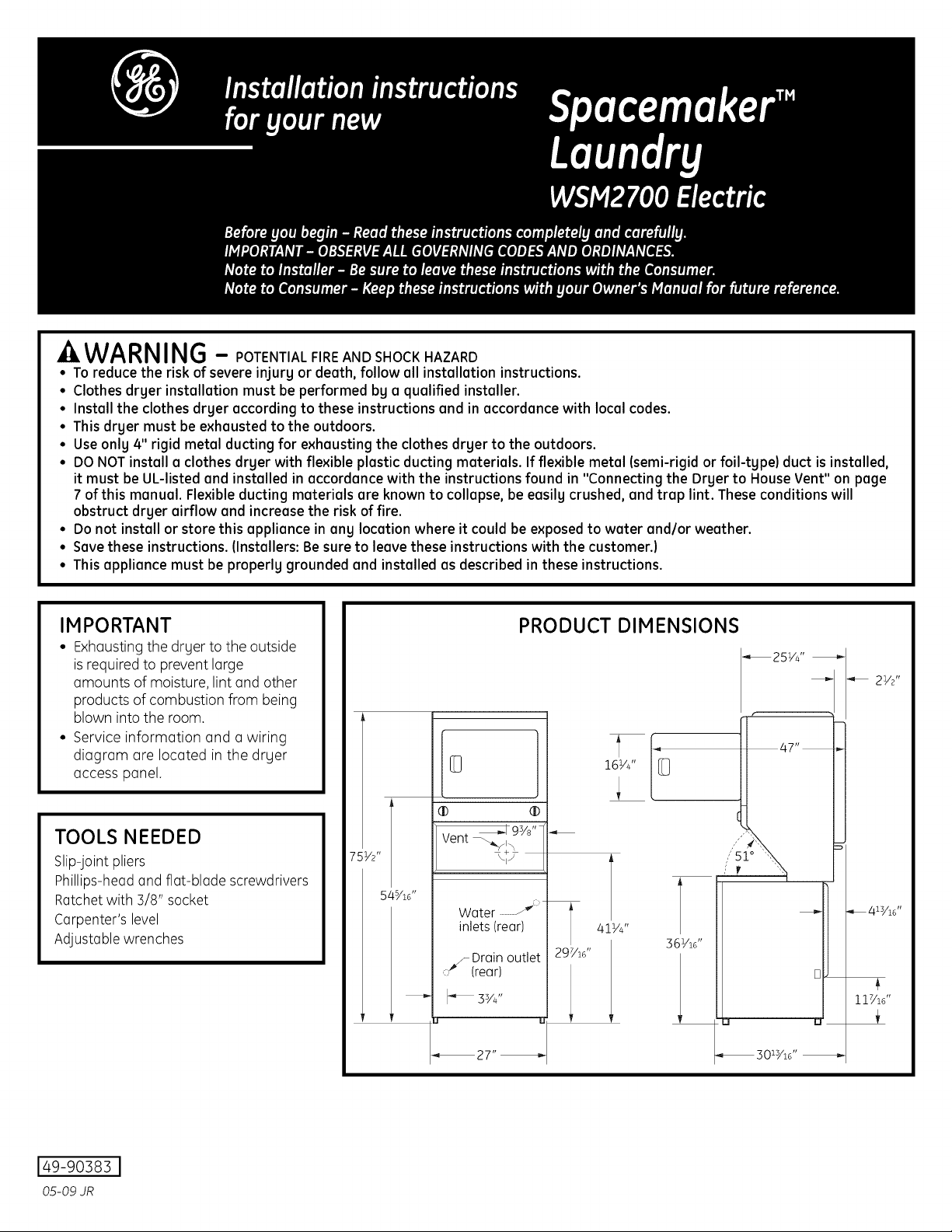
_19_/8 '']
Vent _/_ /
\+/ /
Water ......._:;
inlets (rear)
_S Drainoutlet
(rear)
_27"
PRODUCT DIMENSIONS
41V4"
2 C /16"
36VS
,,," _o_',,,
,, ,,,
' ]
b
_30_Y_8 ''
21/2 ,,
117/18"
149-90383I
05-09 JR
Page 2
Installation Instructions
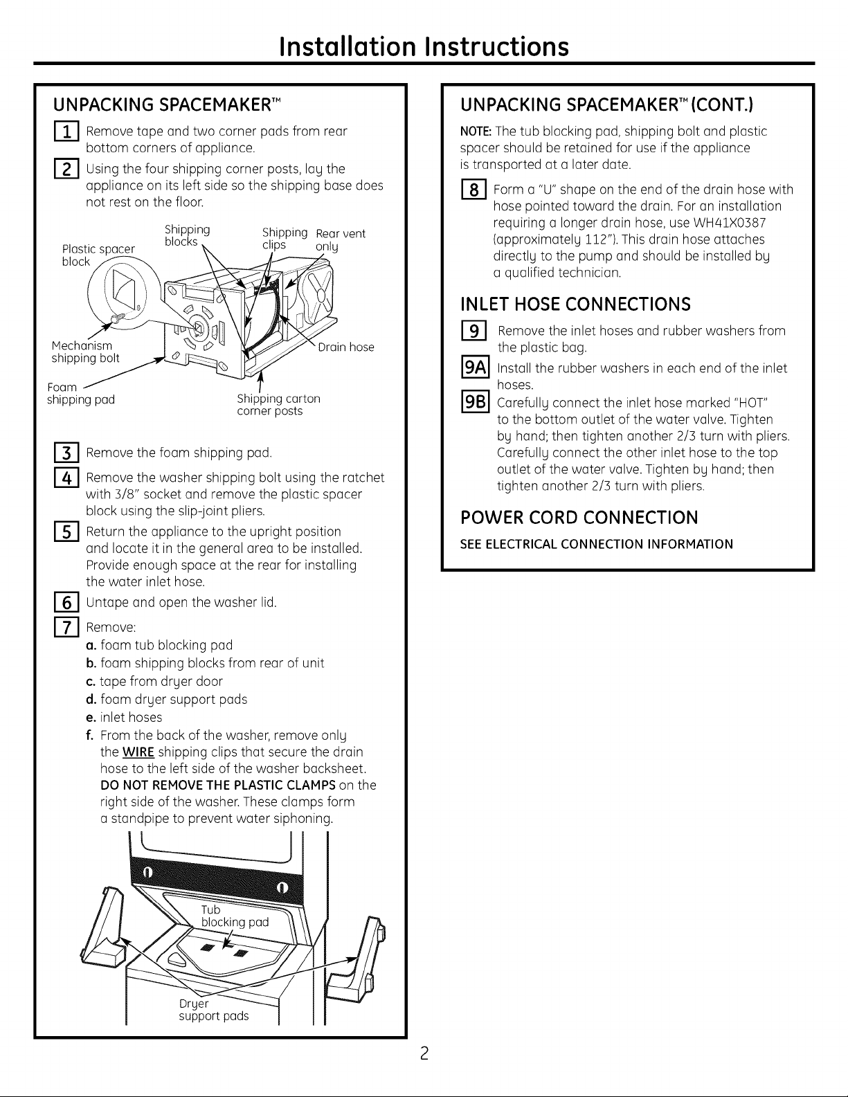
UNPACKING SPACEMAKER'"
I-I-IRemove tope two cornerpods rear
bottom cornersofappliance.
r2-1 using shippingcornerposts,log
thefour the
appliance on its left side so the shipping bose does
not rest on the floor.
Plastic spacer
block
Mechanism "Drain hose
shipping bolt
Foam
shippingpad
Remove the foam shipping pod.
Remove the washer shipping bolt using the ratchet
with 3/8" socket and remove the plastic spacer
block using the slip-joint pliers.
Return the appliance to the upright position
and locate it in the general area to be installed.
Provide enough space at the rear for installing
the water inlet hose.
Untope and open the washer lid.
Remove:
a. foam tub blocking pod
b. foam shipping blocks from rear of unit
c. tope from dryer door
d. foam dryer support pods
e. inlet hoses
f. From the back of the washer, remove only
the WIRE shipping clips that secure the drain
hose to the left side of the washer bocksheet.
DO NOT REMOVETHE PLASTICCLAMPSon the
right side of the washer. These clamps form
o standpipe to prevent water siphoning.
and from
Shipping Shipping Rearvent
blocks clips only
Shipping carton
corner posts
UNPACKING SPACEMAKER'" (CONT.)
NOTE:The tub blocking pod, shipping bolt and plastic
spacer should be retained for use if the appliance
is transported at o later dote.
I-8--1 Form the end of the drain hose with
0 ttU_J
shape
on
hose pointed toward the drain. For on installation
requiring o longer drain hose, use WH41X0387
(approximately 112"). This drain hose attaches
directly to the pump and should be installed by
o qualified technician.
INLET HOSE CONNECTIONS
Remove
I_1 the inlet hoses and rubber washers from
the plastic bog.
r_ install the rubber washers in each end of the inlet
hoses.
I'_"1 Corefully connect the inlet hose marked "HOT"
to the bottom outlet of the water valve. Tighten
by hand; then tighten another 2/3 turn with pliers.
Carefully connect the other inlet hose to the top
outlet of the water valve. Tighten by hand; then
tighten another 2/] turn with pliers.
POWER CORD CONNECTION
SEEELECTRICALCONNECTIONINFORMATION
Dryer
support pads
Page 3
Installation Instructions
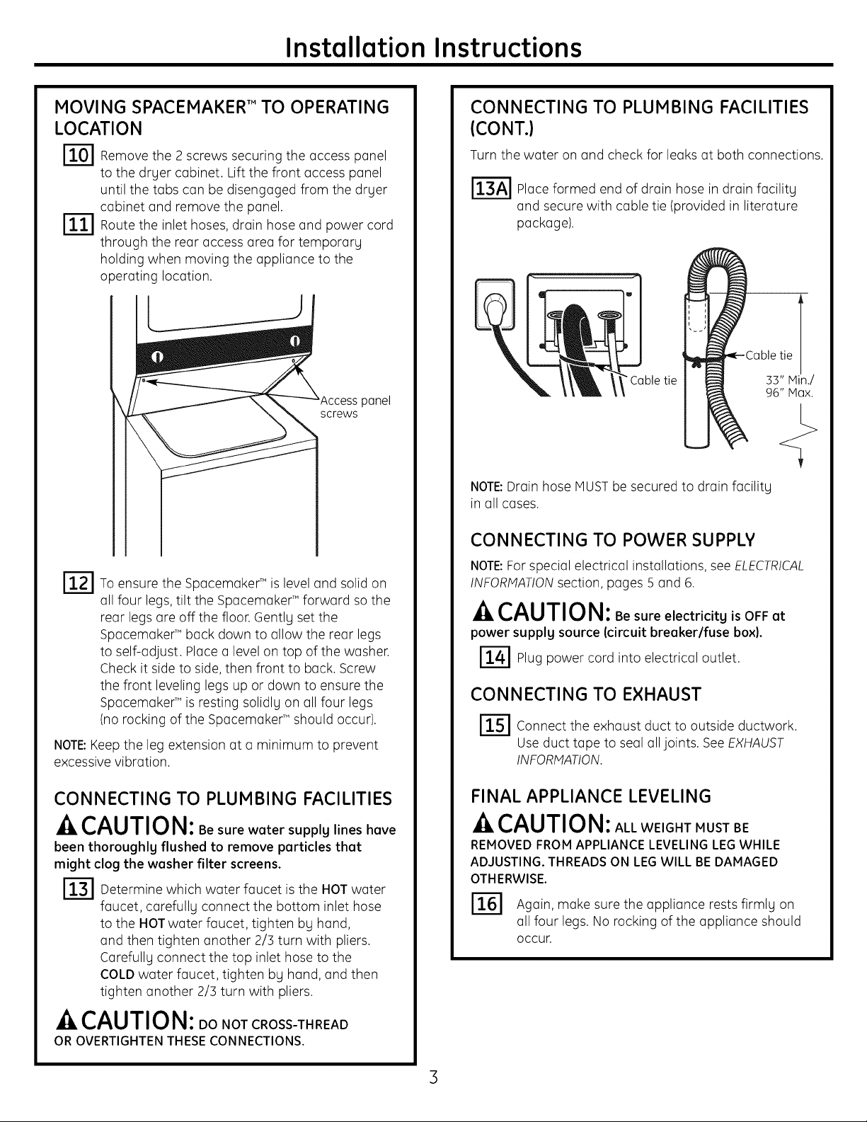
MOVING SPACEMAKER'" TO OPERATING
LOCATION
r_ Removethe 2 screws securing the access panel
to the dryer cabinet. Lift the front access panel
until the tabs can be disengaged from the dryer
cabinet and remove the panel.
r_ Route the inlet hoses, drain hose and power cord
through the rear access area for temporary
holding when moving the appliance to the
operating location.
panel
screws
CONNECTING TO PLUMBING FACILITIES
(CONT.}
Turn the water on and check for leaks at both connections.
r_ Place formed end of drain hose in drain facility
and secure with cable tie (provided in literature
package).
-)
"Cabletie ab_ii_[. _
NOTE:Drain hose MUSTbe secured to drain facility
in all cases.
To ensure the SpacemakerT"is level and solid on
all four legs,tilt the Spacemaker T"forward so the
rear legs are off the floor. Gently set the
Spacemake¢" back down to allow the rear legs
to self-adjust. Place a level on top of the washer.
Check it side to side, then front to back. Screw
the front leveling legs up or down to ensure the
Spacemake¢" is resting solidly on all four legs
(no rocking of the Spacemake¢" should occur).
NOTE:Keepthe leg extension at a minimum to prevent
excessive vibration.
CONNECTING TO PLUMBING FACILITIES
-ACAUTION: Be sure water supply lines have
been thoroughlg flushed to remove particles that
might clog the washer filter screens.
r_ Determine which water faucet isthe HOTwater
faucet, carefully connect the bottom inlet hose
to the HOTwater faucet, tighten by hand,
and then tighten another 2/3 turn with pliers.
Carefully connect the top inlet hose to the
COLDwater faucet, tighten by hand, and then
tighten another 2/3 turn with pliers.
CONNECTING TO POWER SUPPLY
NOTE:Forspecial electrical installations, see ELECTRICAL
INFORMATIONsection, pages 5 and 6.
-&CAUTION: Besure electricity isOFFat
power supplg source (circuit breaker/fuse box).
r_l Plug power cord into electrical outlet.
CONNECTING TO EXHAUST
r_ Connect the exhaust duct to outside ductwork.
Use duct tape to seal all joints. SeeEXHAUST
INFORMATION.
FINAL APPLIANCE LEVELING
_ACAUTION: ALLWEIGHT MUSTBE
REMOVEDFROM APPLIANCELEVELINGLEGWHILE
ADJUSTING.THREADSON LEGWILL BEDAMAGED
OTHERWISE.
r_ Again, make sure the appliance rests firmly on
all four legs. No rocking of the appliance should
occur.
_ACAUTION: DONOTCROSS-THREAD
OROVERTIGHTENTHESECONNECTIONS.
3
Page 4

Installation Instructions
APPLIANCE OPERATIONAL CHECKOUT
IT71 Make sure all packing and shipping materials
are removed, including the washer shipping bolt
and plastic spacer block.
I'_'AI Route drain hose properlg-not coiled or kinked.
I'_"B'I Make sure water inlet hoses are connected
(HOTto HOT)and tightened securelg without
kinks. Turn on water faucets and check for leaks.
ri-f-dTape all joints to make sure exhaust ductwork
is secured without leaks.
Turn on electricitg at the power source,
Turn on the washer and drger and run through
one cgcle. Check all hoses for leaks.
REPLACING FRONT ACCESS PANEL
r_ Reinstall front access panel removed inStep 10.
r_ Place the Owner's Manual and Installation
Instructions in a location where theg can
be found bg the customer.
PLUMBING INFORMATION
WATER SUPPLY REQUIREMENTS
• HOTAND COLDWATERFAUCETS- Must be within 42"
of the appliance water inlet hose connections. The
faucets must be3/4" garden hose-tgpe so inlet
hoses can be connected.
• WATERPRESSURE- Must be between 10 and 120
pounds per square inch with a maximum unbalance
pressure, hot vs. cold flowing, of 10 pounds per
square inch.
• WATERTEMPERATURE- Water heater should be set
to deliver 140° to 150°F(60° to 66°C) in the washer
when HOTwash is selected.
• SHUT-OFFVALVES- Both hot and cold water shut-off
valves (faucets) should be supplied.
• LOCATION - Do not install appliance in an area where
the temperature will fall below freezing. If appliance is
stored or transported in freezing temperatures, be sure
all water from the fill and drain sgstems has been
removed.
DRAIN REQUIREMENTS
• DRAINRATE- The drain or standpipe must be capable
of accepting a discharge at the rate of 16 gallons per
minute.
• DRAINHEIGHT- The drain height must be 33"
minimum and 96" maximum.
• STANDPIPEDIAMETER- The standpipe diameter must
be 1-1/4" minimum. There MUSTbe an air gap around
the drain hose in the standpipe. A snug fit can cause
a siphoning action.
• SIPHONBREAKKIT- Fora drain facilitg less than 53"
high, the hose, coupling and clamps provided in the
machine must be used and, in addition, a siphon break
MUSTbe installed on the back of the machine. Use
Siphon Break Kit WH49X228 and follow instructions
in the kit.
ELECTRICAL CONNECTION
INFORMATION
-AWARNING: Toprevent personel injurg
TURN OFF ELECTRICITYAT POWERSOURCE[CIRCUIT
BREAKER/FUSEBOX)BEFOREINSTALLINGOR
SERVICINGTHISAPPLIANCE.
DO NOT USE AN EXTENSION CORD WITH THIS
APPLIANCE.
THIS APPLIANCE MUST BE PROPERLY GROUNDED.
This appliance must be electricallg grounded in
accordance with local codes and ordinances or,
in the absence of local codes, in accordance with the
NATIONALELECTRICALCODE,ANSI/NFPANO.70-1987.
ELECTRICAL REQUIREMENTS
• This appliance should be connected to an individual
branch circuit with 120/2/40- or 120/208-volt single-
phase 60 Hzelectrical service and should be protected
bg 30-amp time-delag fuses or circuit breakers.
• Use power supplg cord kit marked for use with clothes
drgers.
4
Page 5

Installation Instructions
CONNECTING APPLIANCE USING
3-WIRE CONNECTION
r_ Remove the terminal block cover located at the
rear of the dryer.
Instoll o UL-recognized stroin relief in the one-inch
hole on the drger back below the terminal block
opening.
Install a UL-listed 30A, 3-conductor NEHA 10-]0R-
r3q
tgpe SRDTcord with 3 open-end spade lug
connectors with upturned ends or closed loop
connectors.
Connect the center wire of the power cord to
r-4]
the silver-colored center terminal screw on
the terminal block. Tighten the screw securelg.
Center
er-cotored
screw
3-WIRE CONNECTION (UNGROUNDED
NEUTRAL)
This appliance is manufactured with the neutral
connected to the frame. If local codes do not )ermit
neutral grounding, proceed as follows:
Remove the terminol block occess cover.
Disconnect the green ground wire from the green
ground screw.
Connect green ground wire to center (silver-
colored) terminal of terminal block.
Connect o separate grounding wire (No. 12
or heavier-not supplied) between the green
ground screw and o grounded metal cold water
pipe or other established ground.
Groundclamp
attachto metal
coldwater pipe
Ground
#12minimum
(notsupplied)
Green
groundscrew
_ Connect the two other wires of the power cord to
the outer brass-colored terminals on the terminal
block. Tighten the screws securelg.
[_ Tighten the screws securing the power cord to
the strain relief.
r_ Reinstall the terminal block coven
_4,CAUTION: Besureelectricitg isOFFat power
source (circuit breaker/fuse box).
r_ Plug power cord into electrical outlet.
[_ Return to Step 15 on page 3.
NOTE:THISAPPLIANCEISNOTAPPROVEDFOR120-VOLT
OPERATION.
Green silver-colored
groundwire screw
[_"_ Reinstall the terminal block access cover.
_4,CAUTION: Besureelectricitg isOFFat power
source (circuit breaker/fuse box).
[_'E] Plug power cord into electrical outlet.
rl-_ Return to step 15 on page 3.
NOTE:THISAPPLIANCEISNOTAPPROVEDFOR120-VOLT
OPERATION.
Page 6

Installation Instructions
CONNECTING APPLIANCE USING
4-WIRE CONNECTION
F1"1 Remove the terminal block access cover.
Install UL-listed 30A, 4-conductor NEMA1/4-30-
type STclosed loop terminal power cord and the
strain relief.
Connect the green ground wire of the power
cord to the terminal block bracket with the green
grounding screw.
r-8
Connect the white wire from the power cord
and the green ground wire from the appliance
harness to the center (silver-colored) terminal
of the terminal block.
Connect the black and red wires from the power
cord to the two outer terminals of the terminal
block.
Greenconductor Silver terminal
Terminalblock
groundscrew
(14-30R)
4-wire receptacle
_D groundwire Blackwire
I_-I Check all connection screws to make sure they
are securely tightened.
FT-I Reinstall the terminal block access cover.
Redwire wire
CONNECTING APPLIANCE USING
4-WIRE CONNECTION (CONT.)
A CAUTION: Besureelectricity isOFFat power
source (circuit breaker/fuse box).
F8-1 Plug power cord into electrical outlet.
I_ Return to Step 15 on page 3.
NOTE:THISAPPLIANCEISNOTAPPROVEDFOR120-VOLT
OPERATION.
EXHAUST INFORMATION
WARNING - Toreducetheriskoffire
or personal injury:
• This clothes dryer must be exhausted to the outdoors.
• Use only 4" rigid metal ducting for the home exhaust
duct.
• Use only 4" rigid metal or UL-listed flexible metal
(semi-rigid or foil-type) duct to connect the dryer to
the home exhaust duct. Itmust be installed in
accordance with the instructions found in "Connecting
the Dryer to HouseVent" on page 7 of this manual.
• Do not terminate exhaust in a chimney, awall,
a ceiling, gas vent, crawl space, attic, under an
enclosed floor, or in any other concealed space
of a building.
• Never terminate the exhaust into a common duct
with a kitchen exhaust system. Acombination
of grease and lint creates a potential fire hazard.
• Do not use duct longer than specified in the exhaust
length table. Longer ducts can accumulate lint,
creating a potential fire hazard.
• Never install a screen in or over the exhaust duct.
This will cause lint to accumulate, creating a potential
fire hazard.
• Do not assemble ductwork with any fasteners that
extend into the duct. These fasteners can accumulate
lint, creating a potential fire hazard.
• Do not obstruct incoming or exhausted air.
• Provide an access for inspection and cleaning of the
exhaust system, especially at turns and joints. Exhaust
system shall be inspected and cleaned at least once
a year.
• Remove and discard existing plastic or metal foil duct
and replace with UL-listed duct.
• Remove any lint from the wall exhaust opening.
Internal_ Wallduct
opening__}:_t-'- Checkthatexhaust
__ .... [I hooddamperopens
"_ _ andclosesfreely.
--,,q/
6
Page 7

Installation Instructions
EXHAUST INFORMATION (CONT.)
EXHAUST DUCT LENGTH INFORMATION
• The MAXIMUMALLOWABLElength of the exhaust system
depends upon the type of duct, number of turns, the
type of exhaust hood (wall cap) and all conditions noted
below. Morethan three 90° turns are not recommended.
Rearventonly
NUMBER
OF 90 °
TURNS
0
1
2
3
HOOD OR WALL CAP
• Terminate in a manner to prevent back drafts or entry
of birds or other wildlife.
• Termination should present minimal resistance to
the exhaust airflow and should require little or no
maintenance to prevent clogging.
• Never install a screen over the exhaust duct.
• Wall caps must be installed at least 12" above ground
level or any other obstruction with the opening pointed
down.
TURNS OTHER THAN 90°
• One turn of 45° or less may be ignored.
• Two 45° turns should be treated as one 90°.
CONNECTING THE DRYER TO HOUSE VENT
Rigid Metal Transition Duct
• For best drying performance, a rigid metal transition
duct is recommended.
• Rigid metal transition ducts reduce the risk of crushing
and kinking.
UL-Listed Flexible Metal (Semi-Rigid)Transition Duct
• If rigid metal duct cannot be used, then UL-listed
flexible metal (semi-rigid) ducting can be used (Kit
WX08X10077).
• Never install flexible metal duct in walls, ceilings, floors
or other enclosed spaces.
• Total length of flexible metal duct should not exceed
8 feet (2.4 m).
• For many applications, installing elbows at both the
dryer and the wall is highly recommended. Elbows
allow the dryer to sit close to the wall without kinking
and or crushing the transition duct, maximizing drying
performance.
• Avoid resting the duct on sharp objects.
EXHAUST
HOOD TYPE
A B
56 ft. 42 ft.
46 ft. 36 ft.
34 ft. 28 ft.
32 ft. 18 ft.
Maximum length of 4"
diameter rigid metal duct
CONNECTING THE DRYER TO HOUSE VENT
(CONT.}
UL-Listed Flexible Metal (Foil-Type)Transition Duct
• In special installations, it may be necessary to connect
the dryer to the house vent using a flexible metal
(foil-type) duct. A UL-listed flexible metal (foil-type)duct
may be used ONLYin installations where rigid metal
or flexible metal (semi-rigid) ducting cannot be used
AND where a 4" diameter can be maintained
throughout the entire length of the transition duct.
• In Canada and the United States, only the flexible
metal (foil-type) ducts that comply with the "Outline for
Clothes Dryer Transition Duct, Subject 2158A" shall be
used.
• Never install flexible metal duct in walls, ceilings, floors
or other enclosed spaces.
• Total length of flexible metal duct should not exceed
8 feet (2.4 m).
• Avoid resting the duct on sharp objects.
For best drying performance:
1. Slideone end of the duct over the clothes dryer outlet
pipe.
2. Secure the duct with a clamp.
3. With the dryer in its permanent position, extend the
duct to its full length. Allow 2" of duct to overlap the
exhaust pipe. Cut off and remove excess duct. Keep
the duct as straight as possible for maximum airflow.
4. Secure the duct to the exhaust pipe with the other
clamp.
SEALING OF JOINTS
• All joints should be tight to avoid leaks.
NOTE:The male end of each section of duct must point
away from the dryer.
• Do not assemble ductwork with fasteners that
extend into the duct. They will serve as a collection
point for lint.
• Duct joints can be made air- and moisture-tight by
wrapping the overlapped joints with duct tape.
INSULATION
• Ductwork that runs through an unheated area or
is near an air conditioning duct should be insulated
to reduce condensation and lint buildup.
PARTS AVAILABLE FROM LOCAL SERVICE
ORGANIZATIONS
• Rigid Metal Duct Components
WX8X63 4" x 1' Duct
WX8X64 4" x 2' Duct
WX8XS1 4" Elbow
WX8X59 4" Aluminum Hood
• Flexible Metal Duct Components
WX8XS8 4" Clamps (2)
WX8X59 4" Aluminum Hood
WX08X10077 6' UL-Listed, Flexible Metal (Semi-Rigid)
Duct, 2 Clamps, 2 Close Elbows
Page 8

Installation Instructions
MOBILE HOME INSTALLATION
• Installation must conform to Manufactured Home
Construction and Safety Standard, Title 24 CFR,
Part 32-80.
• The dryer must be exhausted to the outside with
the termination securely fastened to the mobile
home structure.
• The exhaust MUSTNOTbe terminated beneath
the mobile home.
• The exhaust duct material MUSTNOTsupport
combustion.
• For Electrical Connections see CONNECTINGAPPLIANCE
USING4-WIRE CONNECTION.
CONSIDERATIONMUSTBEGIVENTOPROVIDEADEQUATE
CLEARANCESFORINSTALLATIONAND SERVICE.
ALCOVE OR CLOSET INSTALLATION
1"_,,_ 0"_ _ 0..... 0"
60
DOOR VENTILATION OPENING
A minimum of 120 square inches of opening, equally
divided at top and bottom, is required. Air openings are
required to be unobstructed when a door is installed.
A Iouvered door with equivalent air openings for the
full length of the door is acceptable.
When louvers or registers are placed in door openings,
the free air openings of the louvers or registers must
equal 120 square inches.
MISCELLANEOUS REQUIREMENTS
LOCATION
• The appliance must be installed on firm flooring to
minimize vibration during spin cycles. Concrete flooring
is best, but wood base issufficient, provided the floor
support meets FHAstandards.
60 .
• If your dryer is approved for installation in an alcove
or closet, it will be stated on a label on the back of
the dryer.
• TO PREVENT LARGE AMOUNTS OF LINT AND MOISTURE
FROM ACCUMULATING AND TO MAINTAIN DRYING
EFFICIENCY,THIS MACHINE MUST BE EXHAUSTED
OUTDOORS.
• DO NOTinstall this appliance with lessthan
the minimum clearances shown above.
CONSIDERATION MUST BEGIVEN TO PROVIDE ADEQUATE
CLEARANCES FOR INSTALLATION AND SERVICE.
-ACAUTION: DO NOT INSTALLTHIS APPLIANCE
INA CLOSET WITH A SOLID DOOR.
SPECIFICATIONS SUBJECT TO CHANGE WITHOUT NOTICE
• The appliance should not be installed on rugs or
exposed to the weather.
INSIDE EXHAUSTING
• If the installation makes it possible to exhaust to the
outside, there must be a clearance of 4" between the
top of the appliance and the soffit.
 Loading...