

Page 1
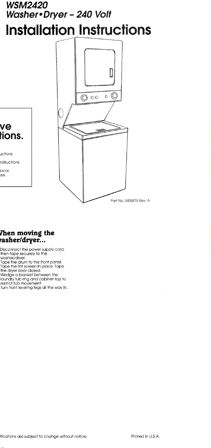
Washer* Dryer - 240 Vo#
Instructions
ve
JCt#on$
locol
_en moving the
D sconnec] the powe_ supDly cord_
then tape securely 10the
washer/drier
Tope the drum to the fforfl poneL
Tope the int screen in place, 1ape
the d_yer does elosed_
Wedge a blanket be_ieen the
Ioundry tub ling ar4d cabinet top to
reset ct tub movement,
Turn front leveling legs ali the way in
\
__P_'_34GSg76 ROY A
ifcations are subject tOchonge without notice. Printed tn U.S.A.
Page 2
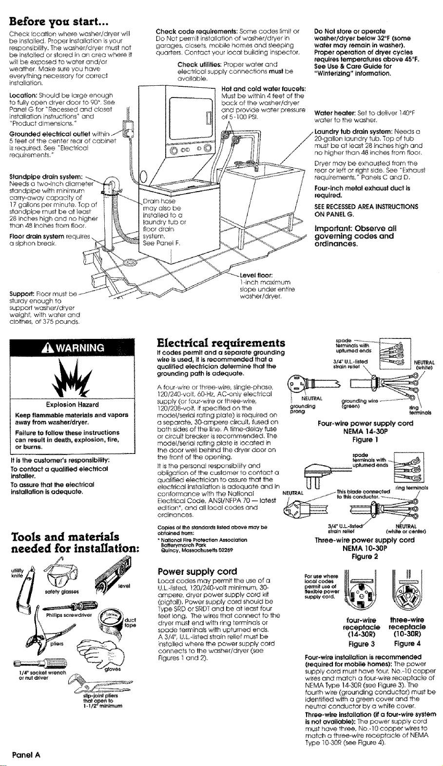
I.oeati_:Shouldbetargeenoagh
tofuhlyopendryerdoo_te_°,See
PanelGfer"Recessedandcbset
insteJtatIonnst_uefions"and
'_P_oductdimensbns,
5 feet ef the center rear of cabinet
is required, See "Electrical
requ rements _
standpipe with m nimum
carry-away cepac t¥ of
17(
standpipe must be of _east
28 Inches high and no highe_
than 48 _nches from floor,
F_or d_in
a sphon break,
Supped': Floe r_ul
sturdy enough to
support washer/dryer
weight, wth water and
ebthes, af 375 pounds
Check c_ requiremetlts: 8©me codes iimit or
Do Not parrot nstaltat_an of washef/d_/e_ n
garage& closets, mobile homes end s!eeplng
quarters, Contact your _oca_building ins_eto_.
Cheek utilities; Proper water and
electrical suppIy connectiens musl be
aveilable,
Not and ¢t.._ water faucets:
MU_ _ce w_h_n 4 _et of the
back of the washer/dryer
cRd prov_t_@water p_sure
of 5 i00 PSk
1-inch maximum
s_ope under entire
washer/dryer,
Do Not siam or operale
w_sherldhler below 32_F (some
w_er may remain in washer),
Proper operation of dwer cycles
requl_es temperatures above 45_F,
See _se & Care Guide for
"Winleilzlng _ lefom_atlon.
Waler heater: _t to deliver t40_F
water to the washer,
rear or taft o I_ghf side, _e _E×haust
requ rements #Par_e_sC and D,
Fourdr'_h melal exhaust duct is
required,
SlOERECESSEDAR_A I_UCTIO_S
ON PANELG.
Important: ObseP,'e all
governing codes and
ordinances.
Explosion Hazard
Keep flammable materials and vapors
away from w_hertdryer,
Faflure to foilew these instru_tions
can tes_lt in de_h_ explosion, fi_,
or burns,
It is the e_fome#s respondbilily
TOconlaet a qualified electrical
I_taller.
tO assure that the e_ectrical
ins_ol|atlan _ adequate,
Tools and materials
needed for installation:
sl_p-je_t p_lecs
tha_ enf_
Panel A
Electrical requirements
If codes permit and a s_arala g_edl_g
_te _ u_d_ It is r_e_meeded that o
quelifie_ electrician determine that the
grounding po_h is adequate,
A four-wire or three-wire singte,.phose,
I20/240 velt 6GoH_AC_enly e_ec_ col
supply (or four, wire Or th_eemvd_e,
120/208 volt, if spec fled on the
model/_edal rating pk_le) is requ red on
a separate_ 30.ampere ci_cu f, tided on
both s_des of the t_ne A time-delay fuse
or circuit bre_ker s reeemmeaded_ The
model/sefial toting plate is leeat_ In
the door welt behind the drye_ door on
the front ot the open ng.
t S the peL_anel respor_s_bii4y and
obliger on of the customer te contact a
qualified electrl¢_n to a_ure that the
e_ctrieat ir_staliation is adequate and n
coniormanee with the National
E@cirtcel Code, ANSI/NFPA 70 -- lat_-st
adrian * and all _oco_c_es and
ordinances,
Ceples el lhe e_r_i_ _t_ above m_y be
"Nal_l ere Pre_io_ Associate
_tte_ym_h P_
Q_ncy, _ch_Iset_s 02269
Loca_cedes may' permit the u_ d a
U& dsted, 1X}/24_'_vett m nlmum 30.
ampere, dryer power supply" cord kt_
(pigtail), Power supply co_d shou_
Type SRDof SRDTand be at east fo_3r
leer _ong The w_resthe1 connect to the
dP_,ermust end w/h ling term na}s or
spade Semifinals with upturned ends,
A 3/4", U £ II_ed stron reief must be
insla/_e_Jwhere ihe power supply cord
connects 1o 1he washer/dryer (see
F_gures 1and 2),
dng fe_a_
3/4°e_LoSst N_A_
Three-wire power supply co_d
NEMA _0-30P
Figure 2
_eex_i_e_er
four-wire three-wire
receptacle receptacle
(14-30R) (10-30R)
FIgL_ 3 Figure 4
FouPwi_e installation _ recommended
(required to_ mobile homes): The power
sup_y cosd must hove four, NO_40 copper
wires and match a fo_r wlre receptacle ot
NEMA Type 1_30R (sere Figure 3). _he
fourth wire (grounding conductor) must be
idenfifi_ w'ith a gree_ cover and the
neutral conductor by o white cover,
Three wire Ir_steilatioe (ifa four-wire system
isnet available):The power suppb/cord
must have three_ No,-10 copper wRes to
match a three-w re receptacle of N_MA
_ype 10&OR (see Fk_ure4),
Page 3
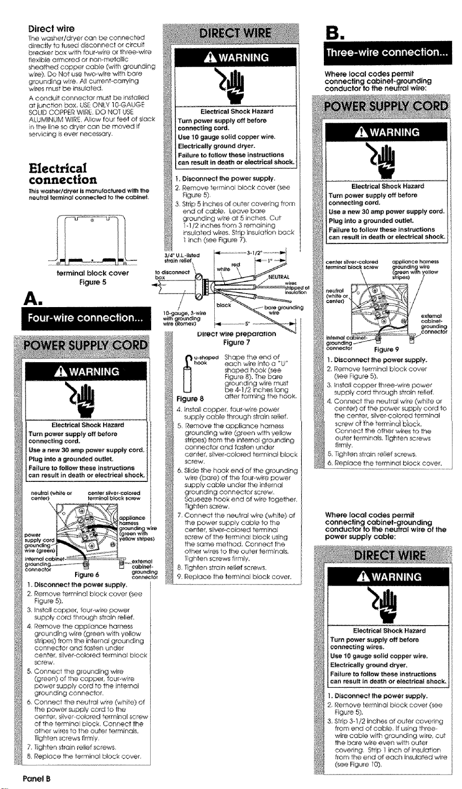
Direct wire
The washe_dryer can be eennec_d
_re_y _ fused diseoenect or circuit
bleaker box wth teu_wire er _h_ee-wlre
fie×ib4e @_nored or non-mete II¢
_#_eo_h_ eO_pet cab!e (with gronnd¾_
wre) DO Net u_ two-w re with bare
grounding wire, AI curre_t<orry ng
w_essFTruStbe ir_suo_d_
A conduit connecter re_t _ Ir,_tc_lied
at l_.notion box, USEONLY _GGAUGE
SOUD COP'PERWg_. DO NOT US_
ALUMINUM W_RE.A_IOw fou_ feei ofslack
n the I_neso dryer con be moved }t
servlcir_g is eve_' n@eessory.
_i_ wesher/d_yer is mam_ractu_ed wffh the
r_utfa| terra.at connected to the eobJnet.
tetmtnal block cover
Figure 5
Ai
L Disconnect _e power supply
2, _emove terminal Dock ¢ove_ (see
Rgure 5),
3. Stdp,5 inches of oufe_ eove_ing from
en_ of cable. Leave bare
grounding wi_e at 5 troches Cut
}-}I2 i(_che_ fitom 3 ;erna_-_ing
nsu_ated wires Strip ineJIot on back
inch (_e Rgure 7),
Be
Where local codes permit
co#netting cobtnei-gro_nc|ing
sonde€for to the neu|ral w_re:
Electrical 81tock Hazard
Turn power su_p_:y off before
coenectiag ¢ord_
U_e a new 30 amp power supply cercL
Pl_Jginto _ groencled s-ut_
Failure tofollow these aspect ens
can result in death or ele¢_icaI shock;
cent_ _e_ _ _tew
Figure 6 g_g
I DIscor_nect the power ,1apply=
2 Remove te_mna bbck cove _e
F@jre5),
3. Irfsto_lcoppec four w re,#owe{
supply co_d through stain _@ief
4. Remove the appliance harness
©or/Rector arid fosk:en under
Center, s_ivef*eolo_ed termina block
5, Connect the g[e nding wire
(green) of the copper, fourow re
powe_ sup__y cord to the internal
grout'cling connector,
6. Connect the neutral wits (white} of
the pewe_ supply cart to the
Figure 7
each wre eta a _'U_
[_ Shape the end 0¢
Figure 8
4. e_sta_tscraper, four-wire power
suppy eatNe th_eugh strain _elief
eo_nector and f<_fenunder
wife (bare) of the fourow re powe_
suppy cab._e unde_ the ntemol
ground ng connector screw.
Squeeze hook end dwire legether,
Tighten _re'w
7 Cor_ne_t the neutral wre O_Zhite}of
the power supply cabs to the
cerlter, s@@_-colorod terrtll_'lol
screw of the termino} back using
the some method, Con_ OCtthe
ot_er wkes 10 the outer term nora,
Tghten screws firmly,
S _qghfen s ralnre_ie_screws,
9, Repk_ce the te_miri<:flbksck cover.
Where local codes permit
co,nearing eobinef_gto_nding
conductor Io the neutral wire of _he
Power supply Cable:
_l_rlo_ S_h_;_:kHazard
Tern power s_ppty off before
connectir_g wires
Use tO gauge soi_ copper w_re.
_e_ricalty ground dryer.
Failure to |allow these ir_st_ectiens
can resuR in death or electrical shock.
other wres to _heouter termhl¢_B
T_ghten screws firm}y,
7. lighten strain re}ief _rews
&Repioce the lorraine b_c_s_cover
Panel B
Page 4

4, Install eeppe, three wire pc,wet
super,,* cabe thraugh stran relief
Slide the hook end of the neutrai
Figure _2
(white o_ canto 0 wre from the
three-wit÷ power suppy cable
undo the center, silv®Pco ored
term no_ screw oFthe formica! b:ock,
Squeeze the hook end oF the wire
together Tighten screw,
6 Connect the othe¢ wr_ 1o the outer
terTenas _s_ng the _me method,
i"igt len screws firmly Gee Figure !2)
7. f_ghten _tain relef screws.
love&
4 Remove the appI_ance harness
grounding wie (green with yellow
sir pes) from the hte_d_ gro_nding
conDo©taR
5 Connect the grounding wi_e
(green wlfh yellow stripes) and the
neutral @_hto) wi_e d the power
supply cord o direct wire cable to
the center, siiver co ored terminal
ecew of the terr:nk_ei b_ock,
Connect the other wies to the
alter tem_inals. Tighten screws (see
Fgure 3).
& Connect o sepon_te copper
grounding wire (NO 0 rain mum)
See Connection details*" for
detai ed ns*ructions,
7 Tighlen s#an reief screws.
8 Replace the terraria biock cover.
F_re t4
Use g_ound r_gwre and clamp
e_embty (Ra_t NO,685463) or NO-10
gauge m_r_ihurn eopt_ g_eund ng
wre.
_aust requirement:
Do No_ use non-met@ t@×ibJevent,
metal vent that issmolder than _ou
riches in diameter or exhaust heeds
wth magnet_ latch÷&
Do Not e×hausf draper_nto a chimney
turt-_ace cold ar duc_ attic or oraw_
spaco, or any other duct u_d for
ven_ing
DO Not }nsto i fiex b_event in enclosed
wa_ls, ce_hgs or floes
If using on existing exhaust system,
cleon lint from entire length of exhaust
sys_m. Mo_e sure exhaust hoo_l is not
plugged with tint.
The exhaust system should be inspected
and cleaned yeorly_
I_eplaee any vinyl at melailtzed p_ostte
foilexhaust vent wffh dgid meter ot
flexible metal 'vent,
U_ duct tape _o _al
at* jeints. Do Not use
screws to seeui_ vent
Where toeat codes DO NOT permit
eo_necttng the cabinef._ounding
conduclof tothe neu#al (white) wire:
F{gure 15
Connect ground_ "w_re_ a
grounded cold ware pipe* wth he
e_amp and then to the extemc4
ground ng conneeIOr on the
washed!dryer (see F_gures 14and ! 5)
Do Not ground to a gas supply pipe or
hot water plpe_ Do Not connect the
power supply cord to el_ctrtcal power
supply until the washer ld_¥er is
permanently grounded,
* O_ourlded c_,_ldwater pipe must t _"_ve
meta car4 nui*y to eiectricai grc_._nd
and not be nfe rupted by plastic, tubby)
OIo!her elecff col ir_sulaN-igr;ohPectors
su_chas hoses f fling& washers or gasket_
{ino_x_i_ water meter or pump) Any
electrical ir/_Jlating connector _neuld be
jumped as shewn tr__igure 16 w*lh a
length of No-4 wte _cure y c_amped to
bare rr,e o! at beth e_ds,
Four-inch dgld metal pipe is preferred
Plan installation to u_ the fewest
number of e}bows and _u_ns
Metatilextbie vent should be _uly
extended and supported when the
dr/e _sin iis final position, DO NOT KNK
OR CRUSH T4E VENL The metal flexible
vent must be fullyexten_d toallow
c_equate exhc_uetair to flew,
Allow as much room as possible when
using ebows or makng turns, Bend vent
gradually ra avoia kinkng Remove
excess flex b_e vent to avoid sagg ng
and kink ng that may resutt n reduced
air few,
Panel C
Page 5

Recessed and closet Recessed and closet
Recessed installation
Fire Hazard
Exhaust dryer outside _ installed in a
e_osef
Use Exhaust Deflector Kit 594609
instatled _na recessed arse_
Failure to do so can result in death or
fire.
To prevent large amounls of !lnl and
moisture from accumulating, to
maintain drying e_iotency and to
p_event exposure !e possible health
hazards, lhB washer/dryer should be
exhausted outdoors.
This wosheddryet may be Insta_led in a
rece_d area of closet.
The hstaiiat_on spac rg tsh inches arid
s minimum ai ow_bl÷. Add tiona
spachg should L_econsideied ter ease
of _ns_aIO,%n, servichg artd camp lance
w_th Iooal codes and ordinances
Ifebset door islnslal/ed, the m h_mum
ur_ebstrueled a;r oper_Tr_gsintop and
bOttOm are requ red, Leuvered doo_s
wth equivalent oi_ open rigs are
acceptable _,,t
Other instai ofions must use the _i_imum
dii'nens ons ndicoted
fron_ view side view
Minimum insfallofion _cir_g
spO¢_g co_ b_ O inches
Closet installation
(Shown withlegs extended 1i_¢h from
boffom o_washe_'/dryerJ
rear view
&
t
] front v_ew
U_ob_mc_eda_ _i_ e_e_r_r_m forCiOset
do_r L_ve_l doorwt_ eq_'_ent _ ope_gs
"°?iil I
be needed
side view
324/8 _
,I
side view
Panel G
Page 6

Maximum{eng_of the e£naust system
depends upoe the type at ven_ used.
number of elbows and the _ype of
exhaust hood. the maxim_Jm ength for
bolh red and flexib e vent B shown in
the ehorl
I_6 0
MaimEd,_
Mobile home instal!_ion
This washer/dryer is s_ilable for mobile
home ins_llatiens.The Insteliatlo_of hhe
washer/dryer m_st oonfeFn to the
M_utoo{_ped _ome Constr_ctlon end
Safety, Ti|le 24 C_R, Par_3280 (formerly
the Federal Standard for Mobile Homes
Construction end Safety, Title 24, HUD
Pod 280, latest edition).
• 4 leg_ • 4 |_, ware{_
1 ar_ h_Se ¢{¢1_ hO_e W_l_
2 161t 5_r
_hem_×l_aurnterq_th u_ng_ _ x _ _e_tt_tlg_J_
ventwith 2e_bows_nd a2-1/_ e_ha_t hc_aa}_B_.
_or exhaust eonfigu_..cC,ions olher than
tho_ sled n the chad. the Book
pressure MUS1NO[ exceed 0.2 iehes
water c@umn at _he back of the
washer/dryer. 9_e back pressure shoud
be cheerio by a qua_ifle'a techn cian.
Ser4ee check: The bobk procure n any
e_haust system used must eat exceed
02 nches of water coumn measured
w_th er. ind ned manometer at the
po_r4 _hat the exhaust vent connects to
the dryer
L:×haosttng_he dryer eetside s
recommended Recessed nsta_l@tion
that isr_ot exhausted outside mus_ u_
_xhe,ssl Deflector Kit WE25XO220 %e
W_ecessed and dose_ nstelbfion
nstructiens." Pan@ G for ueo_ssfructed
air opening _equ}remer#s,
Iftheweshei/_eyer isinsta_iecl#ie
confined area S_eh as e bedroom,
bathroom or cleset_ it m_st be
exheested to the Outside and S_o,nsion
mist be made _orenough air tar
venti_olkxs Check governtr g codes and
ordinances AI_4_refer te ft_e 1Recessed
_nd Close_ installer on inshuctions" on
Panel G,
M exhaust hood sho_ld eo_ the
exhaus_ vent to prevent exhausteG air
from re_urnng nro dryer The curie4 o{
the hood must _ at leas112 nches
from the ground or any ob_ec_ that may
be _ the path of the
FoL_r-inchexhaus_
hood ispreferred.
However a 2t/2
exhaust.
inch exhaust !1cod
may be use@ A 2.
1i2-tnch exhaust hood c_eates greater
back pressure than other hood 1spas.
For permanent installation,a stationary
exheest system is req_ired_
enclosed ©red, #oar encJe_ _e_
Extens on be'hand the ene!osure wl!!
pro"vent iet and me sture budup under
the mobile home,
with washer/drye_ in laundw area,
More than one person _sPeqt_ired to
lift, flit or move the washer/dryer
because of its weight sad size.
Foliate to follow this instruction may
result in injury.
Truck only from Pear to prevent prod_ct
damage.
tnjury Hazard
IPLf on safety @asses and @eves.
Numbers
correspond
to steps.
package Check that al parts were
nduded
_eveling _eg inte the hole
in the rear come_ on the
bottom of he
washeUdryen Push _eg n
untl t snaps in_o p!ace_
Do the t_ame same thhg
w_th the ether even@
_eg in the other rear corner,
Stes 4)
legs n hand check the
ridges for a diamond
morking_ That% how for the
1 With one of the front
leg s supposed to go nto
the hole, Staff to scow _he
legs hie the' holes in the
front comers by hand
%
Use slip-joint pliers to finsn turning the
front legs ,_r4you reach the diamond
mark
Slt_ washer/drye_ onto cardboard o_
_rdbeard befo_:emoving ocpe_ floor to
prevent damage to lloor oove_ng_
I Place a pace
Of cardboard or
hardboard n front of
carton, Now stand the:
washeUdryer upright
Side washeqdryer
Panel D
_ p_venl p_cr
d_ge, dO n_
t_ve Com_
p_Is _r_ the
ca_O_ b_e
c_in e,
out the oadon down one comer.
Remav_ cotton,
Page 7

1 Remove
the two _ea[comer
po_stslocated at the
back of the
washer/dryer.
Remove the two
corner pieces
attached to the lower
front of the
wosher/dryer_ Do Net
_emove the foam
s__pping paces
between the washer
and dryer until the
washef/drye_ is in pace
cor4_
pe_
Numbers
correspond
to steps.
9=
1 O, Move
foam shipp ng
pieces outward
iust enough to
c_ea_ the washer
tid. Untape and
open the washer
Id. The latch
under the dryer witl hold Hidopen.
of baskeh Place hoses w_th other parts
11.30.
1 61Attach hose to bottom (hot
water) !nlet valve opening first;then
second hose to tap (paid wateO n_t
valve. T_ghien coup rigs by hand. Use
pliers to make an addiiiona_ two-thirds
turn.
IMPORTANT: THIS PROCEDURE
MUST BEFOLLOWED TO ASSURE
PROPER INSTALLATION.
SI_ woshe_/drye_ onto eo_dboerd or
hardboard before moving across floor fo
avoid damaging floorcove_Ing.
_J_
1
e_het side of the washed/dryer, move
wa_er/drye_ c_ese to final position so
you con e_ib, complete the follow ng
steps. (Go to Step 20.)
tf you ere working in a closer o_
reoet,se_ area, move theewasheridrye_
into flnai posit en ar'd rernove
cardboa_d,!hardboard from undei"
woshe_/dryen _emove the lv,,o foam
shipp#ng pieces bel'ween the wa_qe_
and dryer and place with the o.ine[
sh p_:xng pieces. Remove the two
Philt ps-head screws ocateo of the lop
of the access panel (See _lu_tret on for
Step 25) Remove access panel end set
access ;:_nel and screws aside,
Complete the fat owing steps through
the aoce% a_ea
up on latch_ Case d,
or cable to drye_ See "Electrical
connection, _ Panels B and C. Do Not
plug power supply cord into ouie or
econnect power a,_this time,
Sl_p and FaffHazard
Use new water inlet hoses.
Failure to follow this instrection
could result in he_l injury, broken
benes_ or bruises from sl_pping and
falling le weter on floor.
I _ _eupS_
end of the nlet hoses, Check that
washers are firmy seated in coup rigs,
Panel E
d_i_ hose
1 7I_O _reventthed_oinhose
from comng off at eaking_ it must
instaled per the following nsttuctiens;
1,Wet the inside end of the dron hose
w#h tap wate_ DO NOT USEANY
O_HE_ LUBRICANT,
2 _ueeze ea_ _ drain hose ciamp
wf_ piers to open and place clamp
over the end of the dran ho_.
3 _-dle ho/@r_g clamp epen_ wo_k end
of dralrl hose onto dran ceneeetor.
4. Posit on c_amp ove_ the drain ho_
area ma_ked _clamp" Release
camp, Camp _ould be 1/4 inch
from end of drain hose,
laundry |_tb dt_n system;
Open yellow clamp and
slide over "hook _end of
drain hose to secure the
l/gd and car ugated
_¢ticns togelher
Floor d_ain systemr Do
Not in,all _hook" end of dran hose to
co rugated _c:rion. Consult your
plurn_r _orproper insta lotion.
eta aundry tub o standp pc. Check fo_
proper length of d_oln ho_e.
1 II Before altaching w_er in et
hoses. _un water 1hrough both faucets
into a bucket [_s wil_get rd o por_Jcies
In water lees that migh_ cog hoses.
Mark whic_ is the her water faucet
(inlet marked !4") to hot water faucet
/s_ach top inlet hose (inter marked 'C")
to co_d water fa _cet Tighten coupings
to the faeoefs by hard, Use p_ers lo
mr_ke final two4h rds turn.
Page 8

Move w_her/dtyer to its permanent
locallon_ Remove cardboard/hardboard
from under was,her/dryer,
wosher!d_yer into final position.
* Ti/}the washer/d_yer orward, raLqng
back legs I inch Off }he floor _ that
the rear _ttqeve/ng legs wil_ ad_us}
Gently _ower the washer!dryer to the
floor
, Check tha_ the washer/dryer _slevel
by plae ng a carpenter's eve on top
of the washer, first side to sde. then
front to back,
- It _1b not/eve!, adjust the front legs
up or down,
,-- Ti_tthe wa_ner!dryer forward,
raising back legs 1 inch Off the floo_
so that the rear _lfqeveling legs
will adjust, Gen_y lower the
washer!dryer to the floon
-- Check that the washer/dryer is
love. Repeat _ needed
CHECK THATDRAIN HOSE IS NOr _ISTED
OR KINKED AND iS SECURELYIN PLACE
access p_ne i_ Step g; remove tt_e
1we foam sh pping pieces between the
wa¢*_e_and drye_ ar!_ place wilh the
ether shipping pieces. !f the exhaust
duct cannot be connected from the
s_deof the washer/dryer the exhaust
duct can be reached from the #ant
through the access panel, Remove the
l_vo _hltiips-heod screws located at the
top of the access panel Set acce_
paneq and screws a_de.
exhaust vent that is need_ to connect
the dryer _o the exhaust ho_ (See
_Exhaus} requ fomentS. '_Pcne_s C and D.)
removed alt the shipp ng pieces,
ncludlng the round _fipp n4;_piece,
D_spose of all moter}aB in proper
n_aRne(
if you do net remove the round shlp_ng
piece_ your wosherldryer may "work"
away from its location,
plasSc _d strap
in laundry tub or standp pe Wrap the
Plast c beaded strap around }he drain
hose and aundry tub orstendp pc,
thread _aded end of strap through
keyhote end Puli until st'_op is tight, Slide
strap into narrow end of keyhoie to lock
strap n p_ace See Rgures A-B
If the wate_ intactfaucets and drain
standpipe are _eeessed, t_ghf|y wrap the
past_ beaded strap around the drain
ho_ and route1 body, (Do Not wrap
strap arour'd }he faucet tsandles or
stems) Thread b_aded end of sirap
through ke,/ho_e end Pul unJiI strap is
tight. Side st_ap nto narrow end of
keyhoie to lock s#ap in ptace, D
_e igure C,
Secure the drain hose to the tub
_ stc_rdpipe wt_ the p|a_ic
_mp Faiture to property secure
drain hose could result in water
demage,
If drain hose eatt4_et be ......
strapped _tO ....... _
place, hose most t 2 _\
be cut exactly to I :'
length so hook _ I I i J
endiS held fighW l . _ '!
over _ ot tub or I _ j _ i
star.pipe= See I I J I J
Figure D, b_*_-_r i
Note: If washeE/dryer IS moved to adjust
drain hose, the washer/dryer must be
leveled e_n Repeat Step 23. Race
cardboard under lhe washer/d_er al_
care_}ly move washer/dryer to avoid
_mag_ng _r covering.
,_._sher/dryer and then }o the exhaust
hood.
, Use the _raightesr path posebie to
avoid 90 ° turns.
• U_ duct tape to seal a_ }ants in the
exhaus_ system
• Use eauiking compeund te s(_sl
exter o_ woli open ng areund e×houst
bead,
REQ_I_M_NTS 8E SUREYOU HAVE
CORRECT E_CT_1CAL SUPPLYAND
RECOMMENDED G_O_NIDING METHOD.
Check the instal!arian _n_uctions _ see
that you hove competed each step
Complete any missed steps before you
cent_nue_
9 ISChech that a_ pa#s ere now
nstal e(:L _e pa_ Ist. Pane_ D, If there b
an extra part go back through steps to
see which step was skipped.
t lCheck that you have a_lof
your tools
check for _eake T_ghten couplings if
there is _eaking_ Do Not ovedighten; ff'_is
coud cause damage to faucets,
sure to tighten screws at each end of
the access pa_eL
{_.YL_ to fuly understand "your new
washer/dryer Open dryer door, Check
to be sure lint sereen is in its p_per
positioA. Wipe out drum,
grounded outlet, Reconnect the _._ower
suppay. Now start _e washer and allow
it to complete the regular cycle,
6 n Start dryer and allow It to
comp_te a ful heat cycle to make sure
;t iswe_ng properly
Yell hove seceess_lly inste|lea_your
new washer/dryer_ TOget the most
efficient llse from your new
washer/dryer, read yau_ _s_L_.,_r._
Keep Installation |nstpJattees and
Guide,
Numbers
co_resportd
to steps.
15.
22.
Panel F ......
 Loading...