

Page 1
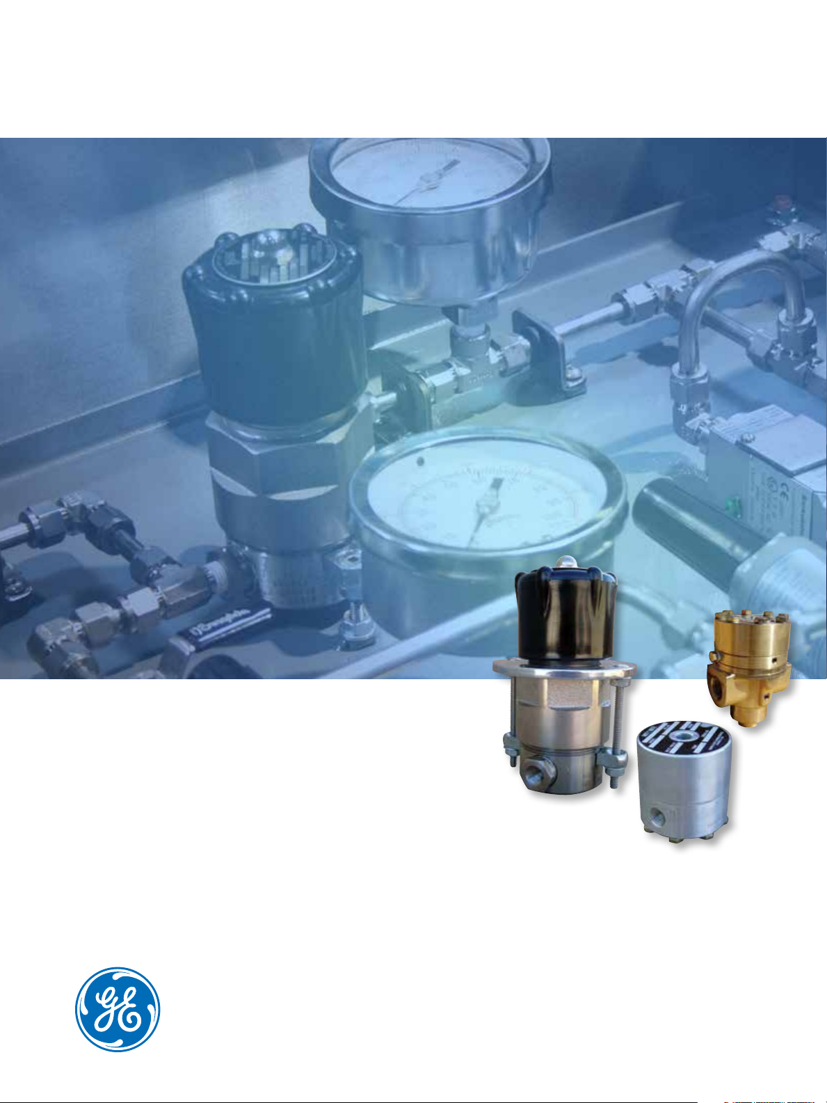
GE Oil & Gas
GE’s Mooney*
Specialty Regulators
The Handloader, Mity-Mite and
Powereactor Regulators
Page 2

2 | GE Oil & Gas
2 | GE Oil & Gas
Page 3
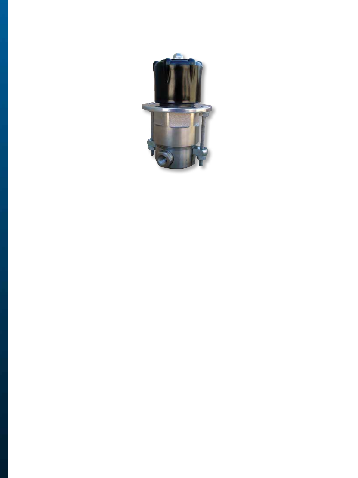
Mooney* Handloader Regulator
This small volume, high pressure regulator has become the standard of industry and science. These instruments
are often referred to as “Loaders” because of their many years of extensive use maintaining constant, extremely
accurate pressure control in the “loading” of dome regulators. However, their accuracy, trouble-free performance, and versatility have led to hundreds of other applications in static, mobile and airborne services. They
are used in component testing, hydraulic and pneumatic operator systems, safety relief valve actuation, critical
rocket fuel transfer and pressurizing problems encountered in missiles and space vehicle projects, to name only
a few.
Features
Maintains constant, accurate pressure control
Simple effective design
Compact, lightweight, easy to mount
Self-contained, self operating
Bubble-tight shutoff
Repeatability and accuracy of spring loading
Greater sensitivity with flexible diaphragm
Ease of adjustment
Corrosion resistant
Interchangeability of parts
Positive downstream protection
GE’s Mooney Regulators | 3
Page 4
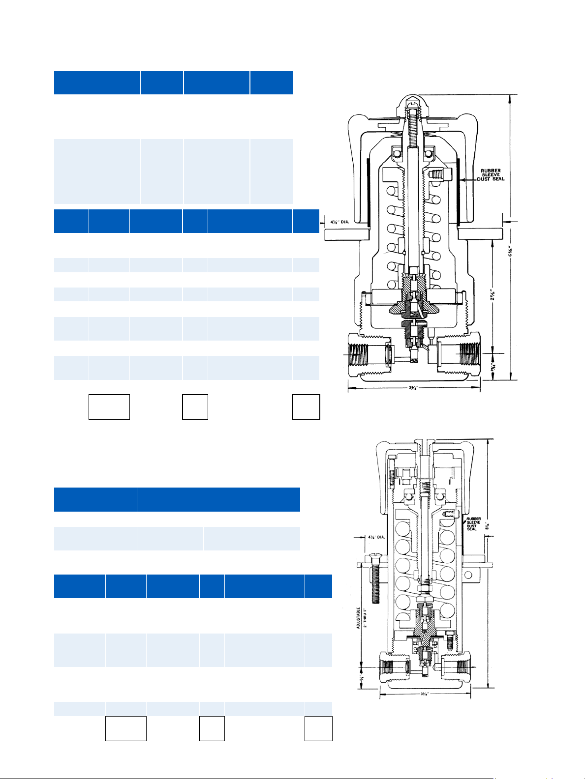
Mooney* Handloader Pressure Reducing Regulator
Model Inlet Pres-
sure
Temperature
Range
C
v
15L w/ Relief System
16 L
15LH w/Relief System
6000 psi -65° to 165° F 0.06
16 LH
15 LX w/Relief
6000 psi
System
16 LX
15 LHX w/Relief
-65° to 165° F 0.06
System
16 LHX
Model Basic
Outlet Range Code End Connection Code
Fig #
15L 10927 2-251 psi A 1/4 Tube MS33649-4
1/4”NPT
L2
P2
16L 11058 3-60 psi B
15 LX 10928 5-150 psi C
16 LX 11089 8-300 psi E
10-750 psi F
15 LH 10929 10-1000 psi H 1/4 Tube MS33649-4
1/4”NPT
L2
P2
16 LH 11059 10-2000 psi K
15 LHX 10930 10-3100
L
psi*
16 LHX 11118
Order
Code =
* Available only in 15LHX and 16LHX models
For all handloaders, add the letter A to the end of the figure number for standard soft
goods (Mylar diaphragm, Nylon seat). For other materials, please contact Oil & Gas.
For example, the complete figure number for a Model 15L with 0-300 psi outlet range and
1/4” FNPT connections and standard soft goods is 10927EP2A.
Model 15L Shown
Mooney* Handloader Pressure Reducing Regulator
Model 15KX w/Relief System
Model 16KX
Inlet Pressure 600 psi 10000 psi
Temperature Range -65° F to +
165° F
Cv 0.018 0.018
Model Basic
Outlet Range Code End Connection Code
Fig #
15KX max
10931 10-2000 psi K 1/4 Tube MS33649-4 L2
Inlet: 6000
psi
16KX max
11060 10-3500 psi M 1/4”NPT P2
Inlet: 6000
psi
15KX max 10932 10-6000 psi P 1/4” Tube AMINCO
16KX max 11229 10-6000 psi
Order
Code =
4 | GE Oil & Gas
-65° F to + 165° F
(for 100000 psi
only)
S2
Model 15KX Shown
Page 5

Mooney* Handloader Pressure Reducing Regulator
Model Max Inlet
(psig)
15L 6000
16L 6000
15LX 6000
16LX 6000
15LH 6000
16LH 6000
15LHX 6000
16LHX 6000
6000
15KX
10000
6000
16KX
10000
Outlet Range
(psig)
2-25
3-60
5-150
8-300
10-750
2-25
3-60
5-150
8-300
10-750
2-25
3-60
5-150
8-300
10-750
2-25
3-60
5-150
8-300
10-750
10-1000
10-3100
10-1000
10-3100
10-1000
10-2000
10-3100
10-1000
10-2000
10-3100
10-6000
10-2000
10-3500
10-6000
10-2000
10-3500
10-6000
10-2000
10-3500
10-6000
10-2000
10-3500
10-6000
Relief System C
Yes 0.06
No 0.06
Yes 0.018
No 0.18
Yes 0.06
No 0.06
Yes 0.018
No 0.018
Yes 0.018
No 0.018
v
Outlet Rise/
1000 psig inlet
drop
3
3
3
5.4
11
3
3
3
5.4
11
1
1
1
1.8
3.7
1
1
1
1.8
3.7
33
33
33
33
5.5
11
11
5.5
11
11
6.9
6.9
6.9
6.9
6.9
6.9
6.9
6.9
6.9
6.9
6.9
6.9
6.9
Average Lockup
(psig)
1.7
1.7
1.7
3
6
1.7
1.7
1.7
3
6
1.7
1.7
1.7
3
6
1.7
1.7
1.7
3
6
19
19
19
19
9
19
19
9
19
19
12
12
12
12
12
12
12
12
12
12
12
12
12
input signals.
GE’s Mooney Regulators | 5
Page 6
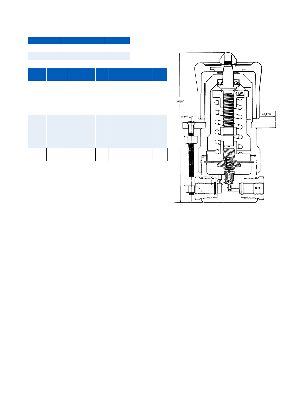
Mooney* Handloader Pressure Reducing Regulator
Model Temperature Range C
v
153 -65° to 165° F 0.17
155 -65° to 165° F 0.04
Model Basic
Outlet Range Code End Connection Code
Fig #
153 11409 2-25 psi
3-60 psi
5-150 psi
8-300 psi
10-750 psi
10-1000 psi
155 11410 2-25 psi
3-60 psi
5-150 psi
8-300 psi
10-750 psi
10-1000 psi
A
B
C
E
1/4”NPT P2
F
H
A
B
C
E
1/4”NPT P2
F
H
Order
Code =
NOTE: Other configurations may be available, please contact Oil & Gas.
P2
Model 15L Shown
6 | GE Oil & Gas
Page 7

Mooney* Mity-Mite Regulator
The Pressure Reducing Mity-Mite is a direct acting, self-contained gas dome regulator of compact design,
weighing approximately 2 lbs. These regulators have a set of integral needle valves for internal dome loading
for gas service. An auxiliary connection is provided in the dome for external dome loading. This port is used
for those applications where the line fluid is a liquid and the dome must be externally loaded from a separate
source of gas pressure, also used for those situations where it is desirable to set the reference dome pressure
form a remote point by means of a Mooney* series 15, combination reducing and relief regulator. Control
pressure is sensed within the regulator.
The Back Pressure Mity-Mite is a an extremely simple, angle
pattern regulator having only one moving part. The diaphragm
senses upstream pressure on the underside and is balanced by
dome pressure on the upper side. In addition, the diaphragm
serves as the valve seal, closing on a nozzle which is an
integral part of the body. This regulator acts to limit upstream
pressure and has no control over outlet pressure. Unlike relief
valves, this unit is designed for continuous throttling service,
maintaining the upstream system pressure between two
pressure levels.
All Mity-Mite back pressure regulators have externally loaded
domes and may be used to control either gases or liquids
providing such fluids do not react chemically with the wetted
regulator materials. The dome must be charged with gas to a
pressure of approximately the desired back pressure setting.
Two connections are provided in the dome. One is intended for
the attachment of a gauge and the other is for dome charging
purposes. An assortment of double needle valve loading
assemblies are available for this purpose as options. Please
contact GE Oil & Gas for details.
Features
Rugged, extremely compact and lightweight
Capacity range equal to conventional regulators
Recommended for small/medium flow conditions
where extreme accuracy is required
Available for pressure reducing and back pressure service
Handles any non-corrosive gas or liquid over a variety of
pressure ranges
Back pressure Mity-Mite series can be applied to corrosive flow media
Materials - Aluminum Alloy/316 SST
GE’s Mooney Regulators | 7
Page 8

Mooney* Mity-Mite Regulator
Model 94
Inlet Pressure 5000 psi
Max. Outlet Pressure 3000 psi
End Connections 1/4” FNPT
Cv 0.1 with 3/32” orifice
Weight Aluminum - 1.6 lbs
0.6 with 3/16’ orifice
Stainless Steel - 4.6 lbs.
Model Dia-
94 2 5000 3000 3/32” 0.14 0.41 1 Yes No Unbal
94 2 5000 3000 3/16’ 0.65 2.3 6.1 Yes No Unbal
Model Basic
94 11486 All Alloy 416 SST 1/4” NPT P2 1/8” 1 3/16” None Nylon PCTFE Nitrile 0 to 165° F A
11233 18-8
Order
Code
=
*All regulators also include options for External Loading or Internal Sensing. External Sensing may be requested on
order for the models specified above for an additional fee.
The Internal Loading option is included at no additional charge for the models specified above.
Fig. #
phragm
Size
(Inches)
Body/
Dome
Material
SST
Max Inlet
(psig)
Trim
Mate-
rial
17-4
PH
SST
Max Outlet
(psig)
End
Conn.
1/4”
MS33649-
4
Orifice C
Code Size Code Orifice Code Valve/
L2 1/4” 2 3/32” 8 Nylon PCTFE Nitrile -65°F to
3/8’ 3 PCTFE PCTFE Nitrile 0 to 165° F E
1/2’ 4 PCTFE PCTFE Nitrile -65°F to
v
Outlet
rise/100 psig
Inlet Drop
Average
Lock up
(psi)
Valve
Seat
PCTFE PCTFE PCTFE 0 to 65°F J
Seat
Gasket
Internal
Loading
Option*
Rubber
Goods
External
Sensing
Option*
Temp Range Code
165°F
165°F
Valve Type
C
G
8 | GE Oil & Gas
Page 9

Mity-Mite Back Pressure Regulator Specifications
Model Connections C
90W
S90W
SD90W
91LW
S91LW
SD91LW
91W
S91W
SD91W
91W
S91W
SD91W
91 1/4” FNPT 0.12 60-6000 psi
Model Basic Fig # Dome Body Diaphragm Temperature
90W
S90W
SD90W
91LW
S91LW
SD91LW
91W
S91W
SD91W
91W
S91W
SD91W
91 M12519-G 316 SST 316 SST FKM 0° F to 200 ° F 60-6000 0.12 4
Order Code = AL = Aluminum
1/4” FNPT 0.44 10-2000 psi
1/4” FNPT 0.44 25-400 psi
1/4” FNPT 0.38 100-2000 psi
1/4” FNPT 0.17 100-3000 psi
10448
11521
11508
10451
11522
11504
10454
11523
11505
10457
11524
11506
316 SST = 316 Stainless Steel
v
Al-Alloy
Al-Alloy
316 SST
Al-Alloy
316 SST
316 SST
Al-Alloy
Al-Alloy
316 SST
Al-Alloy
Al-Alloy
316 SST
Control Range
Al-Alloy
Al-Alloy
316 SST
Al-Alloy
316 SST
316 SST
Al-Alloy
316 SST
316 SST
Al-Alloy
316 SST
316 SST
Nitrile
FKM
FKM
PTFE
PTFE
PTFE
PTFE
PTFE
PTFE
PTFE
PTFE
PTFE
Range
0 to 165° F
0 to 200° F
0 to 200 ° F
-65° F to 200
° F
-65° F to 200
° F
-65° F to 200
° F
Back Pressure
Range (psig)
10-2000 0.44
25-400 0.44
100-2000 0.38
100-3000 0.17
Max
C
v
Weight
(lbs)
1.6
2.5
4
1.6
2.5
4
1.6
2.5
4
1.6
2.5
4
Viton and Teflon are registered trademarks of Dupont.
GE’s Mooney Regulators | 9
Page 10

Mooney* Powreactor Dome Regulator
The Mooney* Powreactors are direct-acting, self-contained, dome-loaded, pressure reducing regulators.
Control pressure sensing is normally accomplished within the Powreactor without the need for external tubing
and valves. This achieves a clean silhouette and minimum envelope size while also making the Powreactor
capable of sustaining much rougher handling than the average regulator.
Features
Instantaneous automatic control
Extremely sensitive to pressure changes
Maintains constant delivered pressure
Balanced valve construction
Ease of cleaning
Avoids chattering and pounding
Positive, tight shutoff
Entirely self-contained
Quick, easy adjustment
Few wearing parts
Fail close on loss of dome pressure
Optional external sensing
10 | GE Oil & Gas
Page 11

As you consider the proper regulator for your application,
please consider the balanced and unbalanced valve
configurations that are available for the Mooney* Specialty
Regulator.
In Unbalanced Valves, the inlet pressure beneath the valve
adds the force needed to open the valve. As the inlet pressure
decreases, the force on the valve decreases, allowing the
valve to open more freely and resulting in higher downstream
pressure. Balanced Valves reduce this effect by equalizing
the pressure above and below the valve, allowing greater
consistency in downstream pressure as the upstream
pressure varies.
Also, consider which outlet pressure sensing configuration is
best for your application. The choices are External Sensing or
Internal Sensing.
The normal configuration of the Mooney* regulator is Internal
Sensing. This method conveys outlet pressure to the bottom
of the diaphragm through an internal sensing passage. This
method provides quick response and accurate control.
Sometimes high-pressure drops across the regulator can
cause turbulence at the outlet port resulting in inaccurate
sensing of the true outlet pressure. This makes the External
Sensing configuration the better choice as the outlet sensing
point is moved away from the turbulence.
Models 202B, 212B, 301B, 311B, 402F, 412F, and 411B can be
converted to external sensing by plugging the internal sense
passage and connecting a tube between the sense volume
and downstream piping.
Model Inlet
Pressure
112B - 3/16” Bal
Valve
112 BR - 3/16”
BR represents relief configuration
6000 psi 6000 psi 0.5
6000 psi 6000 psi 0.5
Max Outlet
Pressure
C
v
Relief Port Relief Material Weight
6 lbs aluminum/
15 lbs stainless
1/4”
MS16142-4
PCTFE 16 lbs
112BR Relief Port:
Internally loaded through integral needle valves
External Dome Loading connection: 1/4” MS16142-4
Model Basic
Fig. #
Body/
Dome
End
Connection
Code Orifice Code Rubber
Goods Seat
Temperature
Range
Code Trim
Material
Material
112B 11220 All Alloy 1/2” FNPT P04 3/16” Bal 9 Nitrile -65° F to 165° FA 18-8 & 17-4
SST
112B 11221 304 SST 1/2” MS33649-8 L04 3/16” Bal 9 EDPM -65° F to 165° FH 18-8 & 17-4
SST
112 BR 11301 304 SST 1/2” & 3/4” GR4 H044 3/16” Bal 9 FKM 0° to 165* F P 18-8 & 17-4
SST
Order
Code =
Seat
Material
PTFE
PTFE
PTFE
GE’s Mooney Regulators | 11
Page 12

Model Inlet Pressure Maximum Outlet
Weight
Pressure
202B 6000 psi 6000 psi 32 lbs.
212B 6000 psi 6000 psi 32 lbs
202F 3500 psi 3500 psi 12 lbs
Internal Sensing with Alternate External Sensing
Connection 3/8” MS16142
Internally loaded through integral needle valves
External Dome Loading connection: 1/4” MS16142-4
Balanced Valve Example
Model Basic
Fig. #
Body/
Dome
Material
Trim
Mate-
rial
202B 11127 304 SST 18-8
& 17-4
SST
212B 11128 304 SST 18-8
& 17-4
SST
202F 11568 Alumi-
num
18-8
SST
Bronze/
Brass
Order
Code =
Unbalanced Valve Example Unbalanced Valve Example
End
Conn.
Code End
Conn
Size
Code Orifice Code Rub-
ber
Goods
Seat
Mate-
rial
Seat
Gasket
Temp Range Code
FNPT P 1/2” 04 1/4” 6 Nitrile PCTFE PCTFE -65°F to
165°F
MS33649-4L 1” 06 3/8” 8 EPDM Kynar PCTFE -65°F to
165°F
1/2” 9 Viton PCTFE PCTFE 0 to 165° F 9
1/2” GR4 Grayloc
1’ GR7 Grayloc
1-1/12” GR14 Grayloc
H044
H067
H0814
FNPT P 1/2” 04 3/16” 5 Nitrile PCTFE PCTFE -65°F to
165°F
MS33649 L 3/4” 05 1/4” 6 EPDM Kynar PCTFE -65°F to
165°F
MS16142 M 1” 06 5/16” 7 Viton PCTFE PCTFE -65°F to
165°F
3/8” 8
1/2” 9
A
H
A
H
P
Internally loaded through integral needle valves
External Dome Loading connection: 1/8” FNPT
Example: A Model 202B with 1/2” MS end connections, a 3/8” orifice, and standard soft goods (Nitrile O-rings and diaphragm,
PCTFE seat and seal gasket), would be Figure No. 11127L048A.
12 | GE Oil & Gas
Page 13

Model Basic
Fig. #
Body/Dome
Material
End
Connection
Code Orifice Code Rubber
301B 11167 All Alloy 1/2” FNPT P04 3/16”
Bal
311B 11221 304 SST 1/2” MS33649-8L04 3/16”
Bal
301B 11213 Carbon
Steel Elect
1-1/2” FNPT
Grayloc
H0814 3/4” 8 KFM P 18-8 & 17-4
Nickel
Coated
311B 11215 Carbon
Steel Elect
3’ x 3” ANSI
2500 RTJ Flg
CJ12 1” Bal
Val
Nickel
Coated
311B 11245 304 SST 2-1/2” - 3” H1225 1-1/2”
Bal
311B 11246 Carbon
Steel Elect
4” FR 31 - 4”
GR31
H1431 1-1/2”
Bal
Nickel
Coated
Order
Code =
301B, 311 B Weights:
1” -1-1/2” = 94 lbs.
3” - 4” = 306 lbs
Internal Sensing (External Sensing Available)
External Dome Loading connection: 1/4” MS16142-4
Goods Seat
Temperature
Range
Code Trim
Material
9 Nitrile -65° F to 165° FA 18-8 & 17-4
SST
9 EDPM -65° F to 165° FH 18-8 & 17-4
SST
SST
9 18-8 & 17-4
SST
9 303 & 17-4
PH SST
9 FKM 0° to 165* F P 303 & 17-4
PH SST
302G Weight: 40 lbs
Internally loaded through integral needle valves
External Dome Loading connection: 1/8” FNPT
Seat
Material
PCTFE
Kynar
PCTFE
PCTFE
PTFE
PTFE
301B Unbalanced
Model Basic
Fig. #
Body/Dome
Material
302G 11567 Aluminum
Bronze/Carbon
Steel
Order
11567
Code =
311B Balanced 302G Unbalanced
End
Connection
Code Orifice Code Rubber
Goods
Temperature
Range
Code Trim
Seat
1/2” FNPT P08 1/4” 4 Nitrile -65° F to 165° FA 18-8 SST
1-1/2’ MS336949-24L08 5/16” 5
3/8” 6
1/2” 7
3/4” 8
1’ 9
GE’s Mooney Regulators | 13
Material
Page 14

Model Basic Fig # Body/Dome
Material
402E 11487P106A Forged Carbon
Steel
11487P107A Forged Carbon
Steel
11487P108A Forged Carbon
Steel
11487P088A Forged Carbon
Steel
11487P086A Forged Carbon
Steel
Order
Code =
402E Weight: 80 lbs
Internal loaded integral needle valves
External Dome Loading connection: 1/8” FNPT
End
Connec-
tion
2’ FNPT 1/2” 3600 1500 0 to 165° F
2’ FNPT 3/4” 3600 1500 0 to 165° F
2’ FNPT 1” 3600 1500 0 to 165° F
1-1/2’
FNPT
1-1/2’
FNPT
Orifice
Size
1/2” 6000 3000 0 to 165° F
1” 6000 3000 0 to 165° F
Max
Inlet
(psi)
Max
Outlet
(psi)
Temperature
Range
Rubber
Goods
Valve Seal
& Gasket
Body
Plug
Gasket
Nitrile PCTFE PCTFE
Nitrile PCTFE PCTFE
Nitrile PCTFE PCTFE
Nitrile PCTFE PCTFE
Nitrile PCTFE PCTFE
Trim
Material
18-8 SST
18-8 SST
18-8 SST
18-8 SST
18-8 SST
Model Basic Fig # Body/Dome
Material
402F 11040P106A Nickel Coated
Carbon Steel
11040P107A Nickel Coated
Carbon Steel
11040P108A Nickel Coated
Carbon Steel
11040P086A Nickel Coated
Carbon Steel
11040P088A Nickel Coated
Carbon Steel
Order
Code =
Model Basic
Body/Dome
Fig. #
411B 11251 304 SST 4’ x 4” ANSI
11252 Aluminum
Bronze/Carbon
Order
11567
Code =
402F Weight: 85 lbs
Internal loaded integral needle valves
External Dome Loading connection: 1/8” FNPT
Material
Steel
Connec-
2’ FNPT 1/2” 3600 3000 -65° F to
2’ FNPT 3/4” 3600 3000 -65° F to
2’ FNPT 1” 3600 300 -65° F to
1-1/2’
FNPT
1-1/2’
FNPT
End
Connection
2500 RGJ Flg
4’ x 4” GR 31
Grayloc
End
tion
Orifice
Size
1/2” 6000 3000 -65° F to
1” 6000 3000 -65° F to
Max
Inlet
(psi)
Max
Outlet
(psi)
Temperature
Range
Code Orifice Code Rubber
Goods
Rubber
Goods
Valve
Seal &
Gasket
165° F Nitrile PCTFE PCTFE
165° F Nitrile PCTFE PCTFE
165° F Nitrile PCTFE PCTFE
165° F Nitrile PCTFE PCTFE
165° F Nitrile PCTFE PCTFE
Temperature
Code Trim
Range
Seat
CJ14 2-1/2” 9 Nitrile -65° F to 165° F A 303 SST and
H1431 2-1/2” 9 EDPM -65° F to 165° F H 303 SST and
FKM 0 to 165° F P 303 SST and
Body
Plug
Gasket
Material
17-4 PH SST
17-4 PH SST
17-4 PH SST
Trim
Material
18-8 SST
17-4 PH
SST
18-8 SST
17-4 PH
SST
18-8 SST
17-4 PH
SST
18-8 SST
17-4 PH
SST
18-8 SST
17-4 PH
SST
Seat
Seal
PTFE
PTFE
PTFE
14 | GE Oil & Gas
411B Weight: 900 lbs
Internally Sensing (External sensing option available)
External Dome Loading connection: 1/2” MS-16142
Page 15

Model Basic Fig # Body/Dome
Material
412E 11489P109A Forged
Carbon Steel
End
Connec-
tion
Orifice
Size
Max
Inlet
(psi)
Max
Outlet
(psi)
Temperature
Range
2’ FNPT 1/2” 3600 1500 0 to 165° F
Rubber
Goods
Valve Seal
& Gasket
Body
Plug
Gasket
Nitrile PCTFE PCTFE
Trim
Material
18-8
SST
412F 11311P109A Nickel Coated
Carbon Steel
Order
Code
=
412E Weight: 80 lbs 412F Weight: 85 lbs
Internal loaded integral needle valves
External Dome Loading connection: 1/8” FNPT
402E Balanced
2’ FNPT 3/4” 6000 3000 -65° F to
165° F
412E Unbalanced
Nitrile PCTFE PCTFE
411B Balanced
18-8
SST
412F Unbalanced
4142F Unbalanced
GE’s Mooney Regulators | 15
Page 16

Powreactor Dome Regulator Chart
Model Diaphragm
Size
94 2 5000 3000 3/32 0.14 0.41 1 Yes No Unbal
94 2 5000 3000 3/16 0.65 2.3 6.1 Yes No Unbal
112B 2 6000 6000 3/16 0.5 0.3 7.1 Yes No Bal
112BR 2 6000 6000 3/16 0.5 0.18 7.1 Yes No Bal
202B 3 6000 6000 3/16 0.7 0.94 2.6 Yes Yes Unbal
202B 3 6000 6000 1/4 1.4 1.5 3.3 Yes Yes Unbal
202B 3 6000 6000 5/16 1.5 2.2 4 Yes Yes Unbal
202B 3 6000 6000 3/8 2.3 2.6 4.4 Yes Yes Unbal
212B 3 6000 6000 1/2 4 0.92 6.7 Yes Yes Bal
202F 3 3500 3000 3/16 0.7 0.94 2.6 Yes No Unbal
202F 3 3500 3000 1/4 1.2 1.5 3.3 Yes No Unbal
202F 3 3500 3000 5/16 1.5 32.2 4 Yes No Unbal
202F 3 3500 3000 3/8 2.4 2.6 4.4 Yes No Unbal
202F 3 3500 3000 1/2 3.4 5 6 Yes No Unbal
301B 5 6000 6000 3/8 2.4 0.99 1.5 No Yes Unbal
301B 5 6000 6000 1/2 5 1.6 1.9 No Yes Unbal
301B 5 6000 6000 3/4 10.7 3.5 2.9 No Yes Unbal
311B 5 6000 6000 1 12.4 0.75 3.7 No Yes Bal
311B 5 6000 6000 1-1/2 26 1 8 No Yes Bal
302G 5 3500 2000 3/8 2.4 0.99 1.5 Yes No Unbal
302G 5 3500 2000 1/2 4.4 1.6 1.9 Yes No Unbal
302G 5 3500 2000 3/4 8.6 3.5 2.9 Yes No Unbal
302G 5 3500 2000 1 11 5.9 3.7 Yes No Unbal
402E 7-3/4 6000 3000 1/2 4 0.62 0.8 Yes No Unbal
402E 7-3/4 6000 3000 3/4 10 1.4 1.1 Yes No Unbal
402E 7-3/4 6000 3000 1 12 2.3 1.5 Yes No Unbal
412E 7-3/4 3600 3000 1-1/2 20 0.55 2.2 Yes Yes Bal
402F 7-3/4 6000 3000 1/2 4 0.62 0.8 Yes Yes Unbal
402F 7-3/4 6000 3000 3/4 10 104 1.1 Yes Yes Unbal
402F 7-3/4 6000 3000 1 12 2.3 1.5 Yes Yes Unbal
412F 7-3/4 3600 3000 1-1/2 20 0.55 2.2 Yes Yes Bal
411B 7-3/4 6000 3000 2-1/2 69 0.65 5.1 No Yes Bal
Max Inlet
(psi)
Max Out-
let (psi)
Orifice
(inches)
C
v
Outlet rise
per 100 psi
Inlet Drop
Average
Lockup (psi)
Internal Load-
ing
Option•
External
Loading
Option•
Valve
Type
* All regulators also include options for External Loading or Internal Sensing. External Sensing may be requested on order for the
models specified above for an additional fee.
The Internal Loading option is included at no additional charge for the models specified above.
16 | GE Oil & Gas
Page 17

Dome Loading Methods
Dome regulators use gas pressure instead of a spring force
to push down on the diaphragm to establish an outlet set
pressure. A pressure down stream that is lower than the
dome pressure results in the diaphragm being pushed
down which opens the valve. Conversely, the valve closes
as the outlet increases above the dome pressure.
The dome loading methods include the use of internal loading needle valves or by the use of a Model 15 Handloader
or other method. By using the Model 15 Handloader,
compensation for variations of pressure changes caused
by increased temperature is carried out by venting gas out
of the dome. Any decrease in dome pressure is maintained
by set point of the Model 15 by adding gas to the dome.
Dome Loaded Regulator uses include:
Propellant transfer systems (pressurization prefabs)
Fuel tank pressurization (test stands)
Test consoles and benches
Jet engine air start sets
Component pressure testing
Hydraulic hoists, power cylinders and presses
High pressure gas wells and pipelines
GE’s Mooney Regulators | 17
Page 18

Regulator Selection Considerations:
Is the flow media liquid or gas?
Is it for pressure reducing or back pressure service?
What is the minimum and maximum inlet pressure?
What is the minimum and maximum outlet pressure?
What is the specific gravity of the media?
What is the minimum and maximum flow rate?
What are the connection requirements?
Other considerations:
Unbalanced Effect = Outlet pressure change affected by the inlet pressure.
Lockup = Normal pressure rise above set pressure required to shut off flow
through the regulator
• Larger diaphragms and smaller valves have lower lockup pressures
Droop = As flow increases through the regulator, the outlet pressure decreases
• Large diaphragms and small orifices have lower droop
Universal Gas Sizing Equation
Q = 520
G•T
Cg =
P1 •
Natural gas@ 60° F
Q = Flow Rate (SCFH)
Cg = Gas Size Coefficient
P1 = Inlet Pressure (psia)
∆P = Pressure Drop Across Valve (∆P = P
P2 = Outlet Pressure (psia)
C1 = Value Recovery Coefficient (C
Cv = Liquid Sizing Coefficient
G = Specific Gravity (0.6 for Natural Gas0 (1.0 for Air)
T = Gas temperature (°Rankine) (T = 460 + °F)
Cg•P1 •sin
520
G•T
Simplifies
1.29
& 0.6 Sg
•sin
3417
[
Q
[
Critical Flow
C
1
P
1 - P2
P
Simplifies
1 = Cg - Cv
1
1.00
1 - P2
∆P
P
1
deg.
]
(psid)
)
]
deg.
Liquid Sizing
Q =CvF
p
∆PA or ∆P Allowable
∆PA = P1 - P
∆PA = .8 (P1 - Pv)
Q = Flow gpm (Gallons per minute)
Cv = Liquid Sizing coefficient (see valve selection)
G = Liquid Specific Gravity
P1 = Inlet Pressure (psia)
P2 = Outlet Pressure (psia)
Pv = Vapor Pressure (psia)
Fp = Piping Swage Factor
2 or
∆PA
G
whichever is less
}
18 | GE Oil & Gas
Page 19

Whether it is the simple operation of the Handloader, the compact Mity-Mite or the configurable
Powreactor, the Mooney* Specialty Regulators provide a stellar history of performance in the
most demanding industrial, laboratory, aero space and defense applications.
PSI
10,000
6,000
5,000
PSI
0.06
Pressure Reducing
For pressure reducing applications, the Mooney* Specialty Regulator line are typically
used for high inlet pressure applications but they work equally well for low inlet
pressures. As seen below, their simple yet durable direct acting design senses down
stream pressure and delivers accurate pressure control over a wide range of inlet
pressures and volumes.
0.6 69
Volume (C )
v
6,000
3,000
2,000
1,000
0.04 0.12 0.17
Back Pressure
The back pressure versions of the Mooney* Specialty Regulator line provide
the same reliability and proven performance and operate by sensing
upstream pressure and throttling the valves to maintain inlet pressure.
0.44
Volume (C )
v
GE’s Mooney Regulators | 19
Page 20

GE Oil & Gas
2822 S. 1030 West
Salt Lake City, UT 84119
T: +1 801.487.2225
F: +1 801.487.2587
Visit us online at: www.ge.com/energy
©2014, General Electric Company
All Rights Reserved
*Trademark of General Electric Company
GEA19588 Mooney Specialty Regulator
Rev 07.2014
 Loading...