How it Works
Log In / Sign Up
Buy Points
How it Works
FAQ
Contact Us
Questions and Suggestions
Users
GE
Loading...
U
UVB36
2
UVB36DK
UVB36DK1BB
UVB36DKBB
2
UVB36SK
UVB36SK1SS
UVB36SKSS
2
UVC7300
2
UVC7300SLSS
2
UVC9300
UVC9300SLSS
3
UVC9360
UVC9360SLSS
2
UVD6301DP
UVD6301S
UVD6301SP
UVD6361DP
UVD6361S
UVD6361SP
UVD-EVRDNR
UVD-EVRDNR(-P)
UVD-XP3DNR
2
UVD-XP3DNR(-P)
UVH13012MSS
2
UVH13013MDS
2
UVH13013MTS
2
UVH13014MWM
2
UVW8301
2
UVW8301SLSS
4
UVW8304
UVW8304SP
UVW8306SLSS
UVW8361
2
UVW8361SLSS
4
UVW8364
UVW8364SP
UVW8366SLSS
UVW9301
UVW9301BLTS
2
UVW9301SLSS
3
UVW9304
UVW93042P
UVW9361
UVW9361BLTS
2
UVW9361SLSS
2
UVW9364
UVW93642P
UVW9484
UVW9484SP
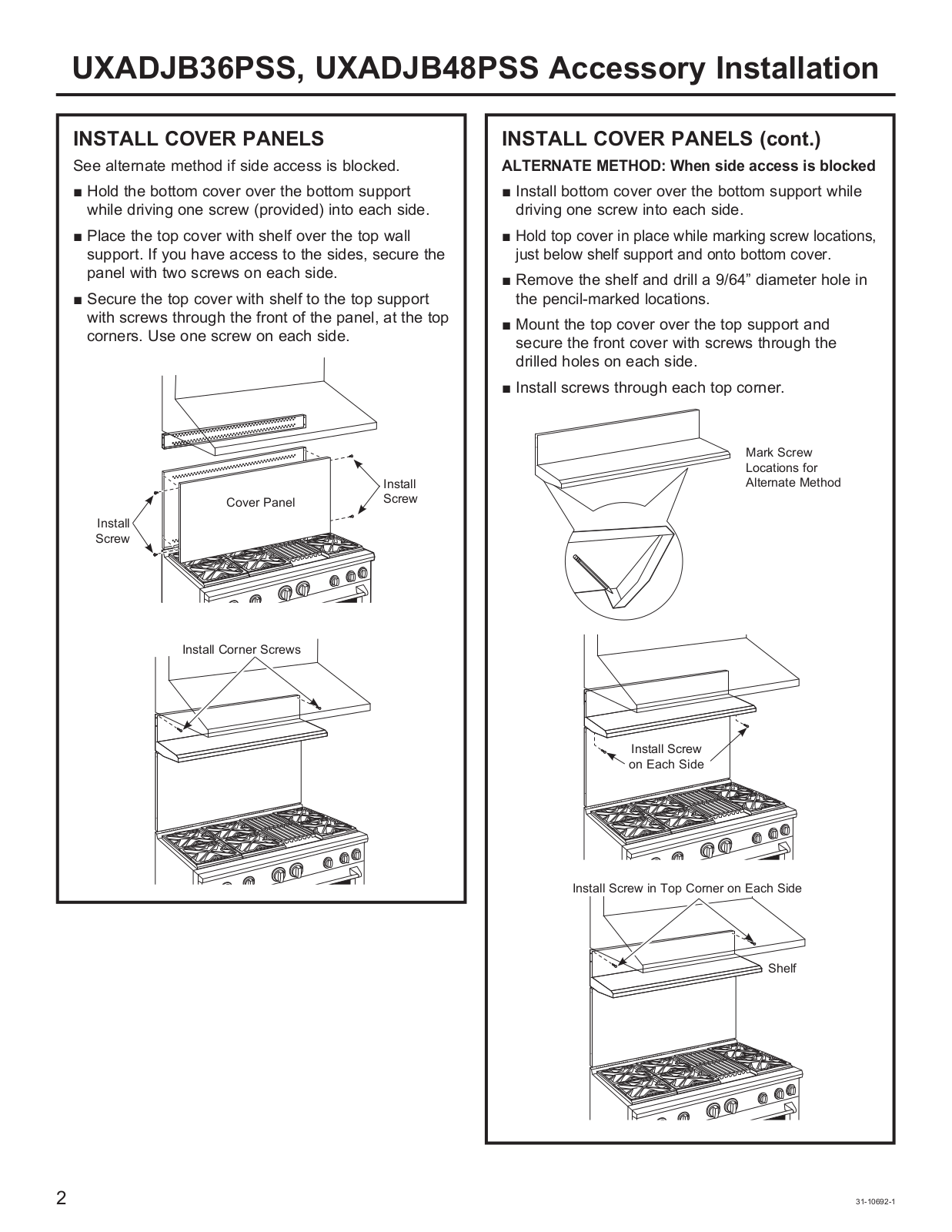
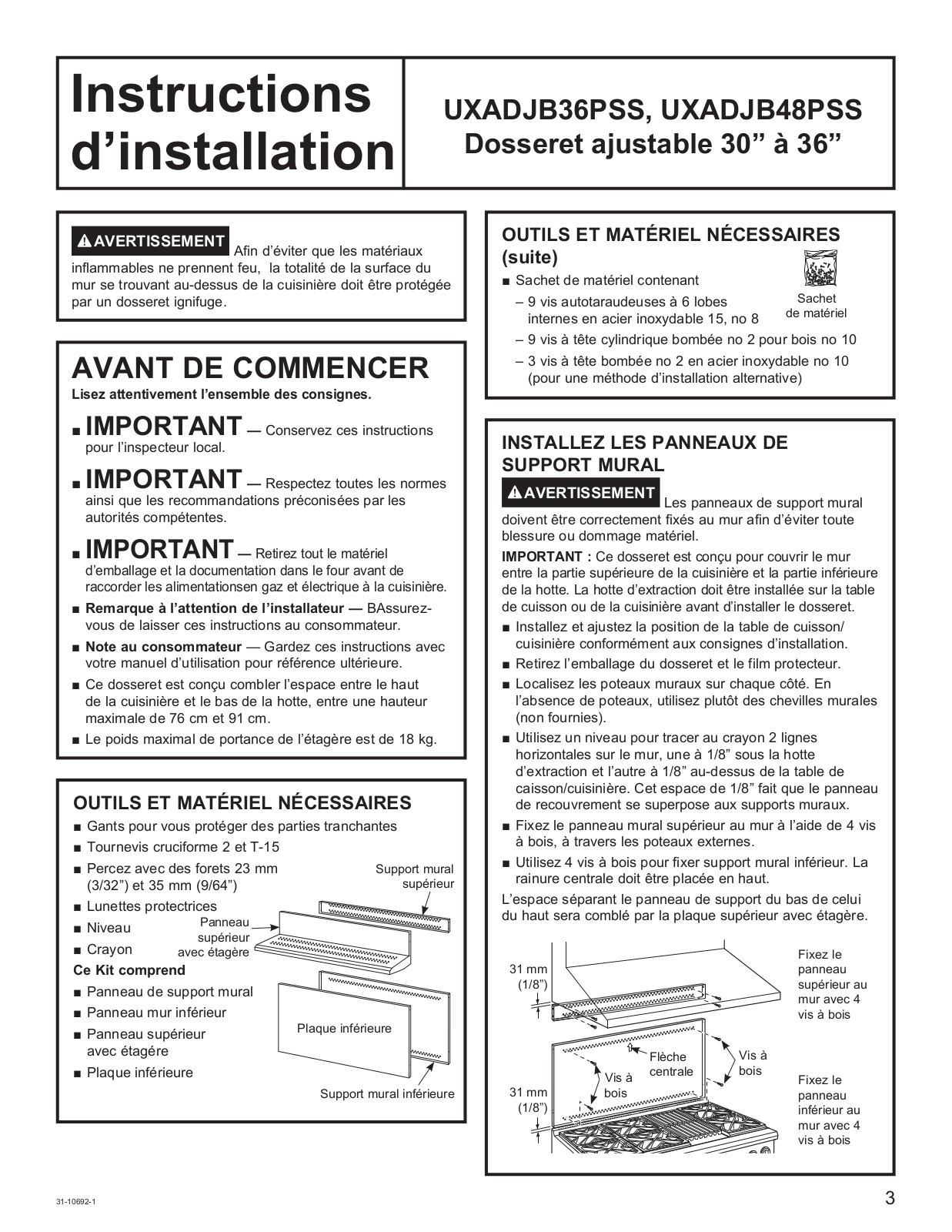
UXADJB36PSS
UXADJB48PSS
V
V21W
4
V228
3
V250
2
V2FC
6
V2FD
6
V2FN
6
V2FS
V2FW
6
V3SL
5
V3ST
5
v6
V7768
V7769
V7865 Series
V935
Valve Actuators
Valve Regulators Mooney_Flowgrid_iom
Valve Regulators Mooney Flowgrid Slam
Valve Regulators Mooney FlowMax
Valve Regulators Mooney Specialty
ValVue ESD
ValVue-FF
VAT20
VAT200
VAT2000
2
VAT2000 Series
VAT300 Series
VB5
8
vb6
vb7
vb8
VBC
6
VBE
4
VBSR1070
VBSR2060
VBSR2080
VBXR1060
VBXR1070
VBXR2070
VCL1000
VCL1500
VCL400
VCL600
VCL800
VCR
ve735am
Ventila
Ventilation Hood
V-LOG
Loading...
Loading...
Nothing found
UXADJB48PSS
Installation Guide
8 pgs
1.77 Mb
0
Table of contents
Loading...
GE UXADJB48PSS, UXADJB36PSS Installation Guide
...
GE Installation Guide
Download
Specifications and Main Features
Frequently Asked Questions
User Manual
Download
Page 1
Page 2
Page 3
Page 4
Page 5
Page 6
Page 7
Page 8
Loading...
+
hidden pages
Unhide
You need points to download manuals.
1 point = 1 manual.
You can buy points or you can get point for every manual you upload.
Buy points
Upload your manuals
 Loading...