

Page 1

SAFETY INFORMATION .............3
USING THE HOOD
Controls ..................................5
Chef Connect .............................5
CARE AND CLEANING
Filters ................................... 6
Surfaces ..................................7
Lights ....................................7
INSTALLATION INSTRUCTIONS ....8
TROUBLESHOOTING TIPS ..........18
LIMITED WARRANTY .............. 22
ACCESSORIES ...................... 23
CONSUMER SUPPORT ............. 24
OWNER’S MANUAL &
INSTALLATION
INSTRUCTIONS
UVW8301
UVW8361
FRANÇAIS
Pour une version français de
ce manuel d’utilisation, veuillez
visiter notre site web à l’adresse
GEAppliances.com.
Write the model and serial
numbers here:
WALL HOODS
GE is a trademark of the General Electric Company. Manufactured under trademark license.
Model # _________________
Serial # _________________
You can find them on a label
on the inside of the hood.
Para consultar una version en
español de este manual de
instrucciones, visite nuestro sitio de
internet GEAppliances.com.
49-2000895 Rev. 1 05-21 GEA
ESPAÑOL
Page 2

THANK YOU FOR MAKING GE APPLIANCES A PART OF YOUR HOME.
Whether you grew up with GE Appliances, or this is your first, we’re happy to have you in the family.
We take pride in the craftsmanship, innovation and design that goes into every GE Appliances
product, and we think you will too. Among other things, registration of your appliance ensures that we
can deliver important product information and warranty details when you need them.
Register your GE appliance now online. Helpful websites and phone numbers are available in the
Consumer Support section of this Owner’s Manual. You may also mail in the pre-printed registration
card included in the packing material.
2 49-2000895 Rev. 1
Page 3
IMPORTANT SAFETY INFORMATION
READ ALL INSTRUCTIONS BEFORE USING
SAFETY INFORMATION
WARNING
ELECTRIC SHOCK OR INJURY TO PERSONS,
OBSERVE THE FOLLOWING:
A. Use this unit only in the manner intended by the
manufacturer. If you have questions, contact the
manufacturer.
B. Before servicing or cleaning unit, switch power off
at service panel and lock the service disconnecting
means to prevent power from being switched
on accidentally. When the service disconnecting
means cannot be locked, securely fasten a
prominent warning device, such as a tag, to the
service panel.
C. Do not use this unit with any solid-state speed
control device.
D. This unit must be grounded.
CAUTION
ONLY. DO NOT USE TO EXHAUST HAZARDOUS
OR EXPLOSIVE MATERIALS AND VAPORS.
CAUTION
TO PROPERLY EXHAUST AIR, BE SURE TO DUCT
AIR OUTSIDE. DO NOT VENT EXHAUST AIR INTO
SPACES WITHIN WALLS OR CEILINGS OR INTO
ATTICS, CRAWL SPACES OR GARAGES.
TO REDUCE THE RISK OF FIRE,
FOR GENERAL VENTILATING USE
TO REDUCE RISK OF FIRE AND
WARNING
TO PERSONS IN THE EVENT OF A RANGE TOP
GREASE FIRE, OBSERVE THE FOLLOWING*:
A. SMOTHER FLAMES with a close-fitting lid, cookie
sheet or metal tray, then turn off the burner. BE
CAREFUL TO PREVENT BURNS. If the flames do
not go out immediately, EVACUATE AND CALL
THE FIRE DEPARTMENT.
B. NEVER PICK UP A FLAMING PAN—You may be
burned.
C. DO NOT USE WATER, including wet dishcloths or
towels—a violent steam explosion will result.
D. Use an extinguisher ONLY if:
1. You know you have a Class ABC extinguisher,
and you already know how to operate it.
2. The fire is small and contained in the area where
it started.
3. The fire department is being called.
4. You can fight the fire with your back to an exit.
* Based on “Kitchen Fire Safety” published by NFPA.
TO REDUCE THE RISK OF INJURY
READ AND SAVE THESE INSTRUCTIONS
49-2000895 Rev. 1 3
Page 4
IMPORTANT SAFETY INFORMATION
READ ALL INSTRUCTIONS BEFORE USING
WARNING
RANGE TOP GREASE FIRE:
A. Never leave surface units unattended at high
settings. Boilovers cause smoking and greasy
spillovers that may ignite. Heat oils slowly on
medium settings.
B. Always turn hood ON when cooking at high heat or
when flambéing food (i.e. Crepes Suzette, Cherries
Jubilee, Peppercorn Beef Flambé).
C. Clean ventilating fans frequently. Grease should not
be allowed to accumulate on fan or filter.
SAFETY INFORMATION
D. Use proper pan size. Always use cookware
appropriate for the size of the surface element.
WARNING
ELECTRIC SHOCK OR INJURY TO PERSONS,
OBSERVE THE FOLLOWING:
A. Installation work and electrical wiring must be
done by qualified person(s) in accordance with all
applicable codes and standards, including fire-rated
construction.
B. Sufficient air is needed for proper combustion and
exhausting of gases through the flue (chimney) of
fuel burning equipment to prevent back drafting.
Follow the heating equipment manufacturer’s
guidelines and safety standards such as those
published by the National Fire Protection
Association (NFPA), the American Society for
Heating, Refrigeration and Air Conditioning
Engineers (ASHRAE) and the local code authorities.
TO REDUCE THE RISK OF A
TO REDUCE THE RISK OF FIRE,
C. When cutting or drilling into wall or ceiling, do not
damage electrical wiring and other hidden utilities.
D. Ducted fans must always be vented to the outdoors.
E. When applicable, install any makeup (replacement)
air system in accordance with local building
code requirements. Visit GEAppliances.com for
available makeup air solutions.
F. Turn off breaker to adjacent rooms while working.
WARNING
USE ONLY METAL DUCTWORK.
Ŷ'RQRWDWWHPSWWRUHSDLURUUHSODFHDQ\SDUWRI\RXU
hood unless it is specifically recommended in this
manual. All other servicing should be referred to a
qualified technician.
TO REDUCE THE RISK OF FIRE,
How to Remove Protective Shipping Film and Packaging Tape
Carefully grasp a corner of the protective shipping film
with your fingers and slowly peel it from the appliance
surface. Do not use any sharp items to remove the film.
Remove all of the film before using the appliance for the
first time.
To assure no damage is done to the finish of the
product, the safest way to remove the adhesive from
packaging tape on new appliances is an application of
a household liquid dishwashing detergent. Apply with a
soft cloth and allow to soak.
NOTE: The adhesive must be removed from all parts.
NOTE: For further cleaning instructions/suggestions,
please refer to the Care And Cleaning section.
READ AND SAVE THESE INSTRUCTIONS
4 49-2000895 Rev. 1
Page 5
Controls
1
USING THE HOOD: Controls / Chef Connect
2
245
4
3
7
36
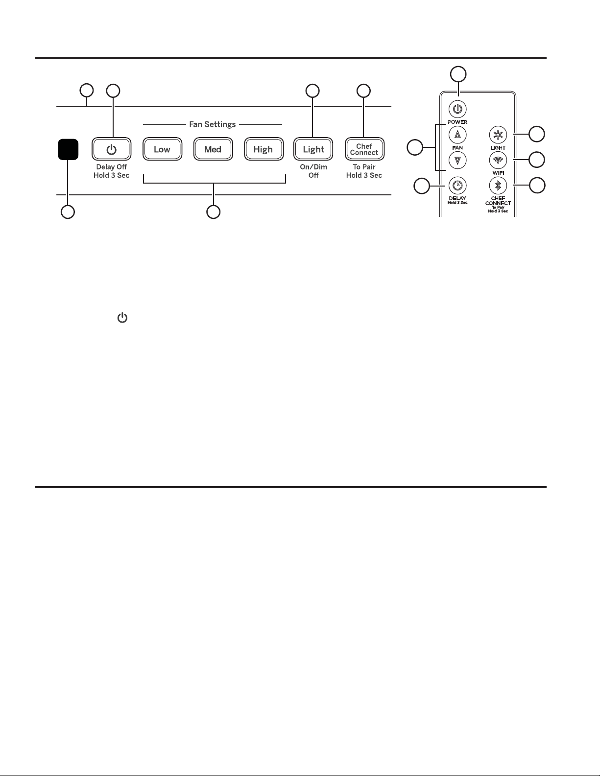
1. Rangehood Control Panel: The control panel
is located on the front of the canopy. The position
and function of each control button are noted below.
2. Fan On/Off: On/Off switch for the fan. The fan
can be operated by pressing any of the fan setting
buttons. Hold for 3 seconds to activate Delay Off
feature, which automatically turns the fan off after
15 minutes.
3. Fan Settings: Speed control for fan. Press the
button Low for LOW speed, Med for MEDIUM
speed, and High for HIGH speed. On Remote,
press Ÿ to increase fan speed, press ź to
decrease fan speed, including Boost.
4. Light: On/Dim/Off switch for the LED lights. Press
the Light button to turn the lights on, again to set the
lights to dim setting, and again to turn the lights off.
8
Remote Control
5. Chef Connect: This is a Bluetooth
for use with other compatible Chef Connect enabled
products on a cooktop or range. When the device is
paired, the light and fan will turn ON at the Default
Sync Settings upon receiving a command from the
range or cooktop. It will remain ON at that setting until
the user changes it. To pair devices, hold down the
Chef Connect button for 3 seconds. To turn it back
off, hold the button down for another 3 seconds. See
the Chef Connect section for more details.
®
pairing feature
6. IR Sensor: Remote control receiver when used
with remote control kit (UXRC1).
7. Wi-Fi (Remote only): Not available.
8. Delay Off (Remote only): Press and hold
Delay Off to toggle Delay Off function.
5
Chef Connect
Chef Connect Operation Bluetooth® Connection
To pair with another device:
To start the pairing process on the hood, press and hold
the Chef Connect button for 3 seconds. The backlight
for all the icons will light up until the hood is paired with
the range or other device. If the pairing is successful,
the backlights of all five buttons will flash simultaneously
three times and then turn off and the backlight for the
Chef Connect button will turn on.
It will time out after 2 minutes if the pairing is not
completed, after which the pairing sequence will need to
be restarted.
To cancel pairing:
To cancel the pairing, hold the Chef Connect button
down for 3 seconds and then turn off the hood.
49-2000895 Rev. 1 5
Default Sync Settings:
The factory default setting for the light will be the brightest.
The factory default setting for the fan sync will be OFF.
The user can change the Default Sync Settings by
pressing and holding the Low button for 3 seconds.
This will enter the Default Settings Mode. Once in this
mode, the backlights for all buttons will blink on/off
indefinitely and the fan and light will switch to the current
Default Sync Setting, so the user knows what the current
default value is. At this time, set the light and fan to the
desired default levels. Once the user is satisfied with the
selection, press and hold the Off button for 3 seconds.
This will exit this mode. At that time the backlights
will stop blinking and the state of the fan and light will
change back to their prior state before entering the
Default Settings Mode.
Page 6
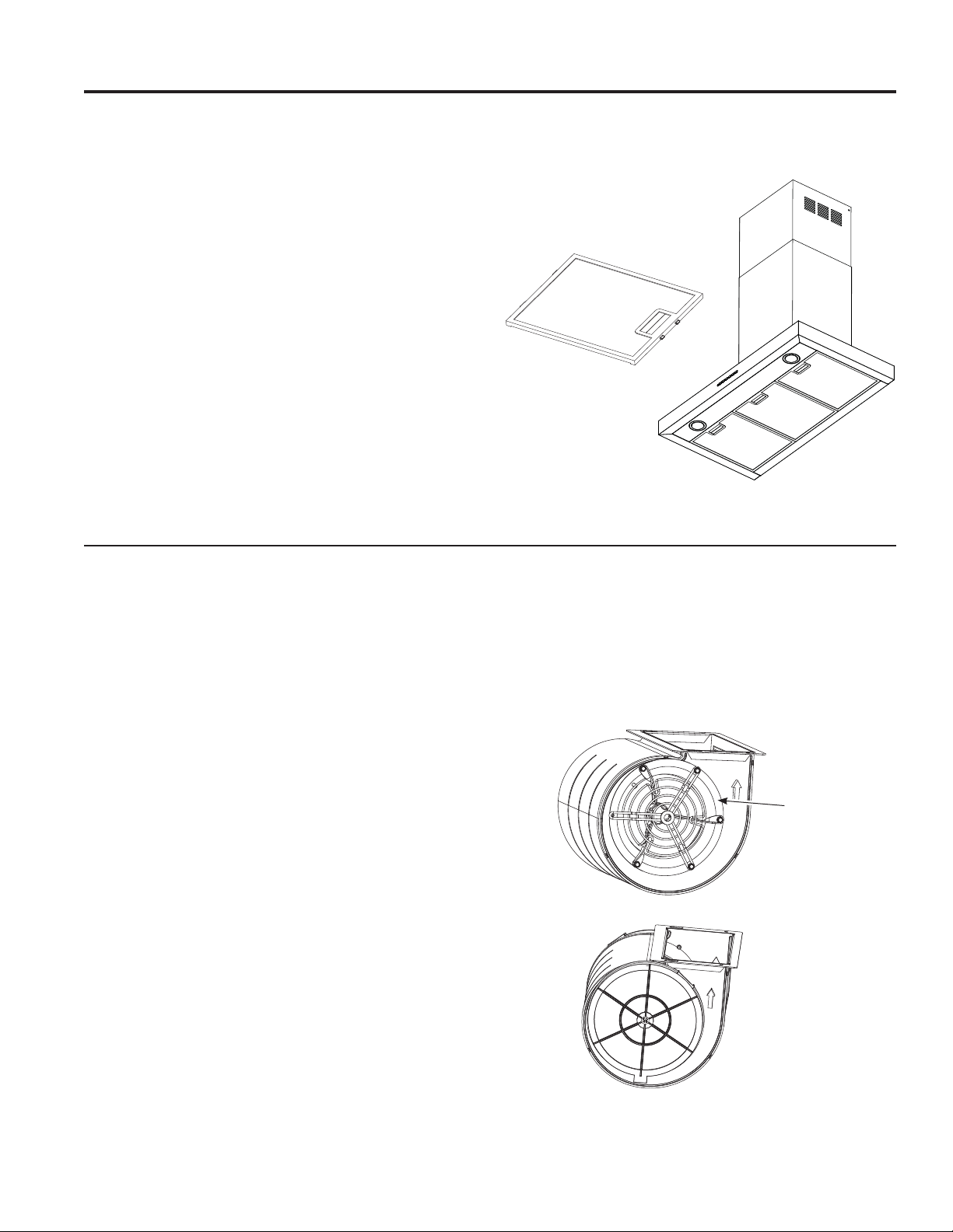
Filters
Be sure the circuit breaker is off and all surfaces are cool before cleaning or servicing any part of the vent hood.
Metal Grease Filter
The metal filters trap grease during cooking.
The filters must ALWAYS be in place when the hood is in
use. The grease filters are dishwasher-safe and should be
cleaned every month, depending on usage of the hood.
To remove:
Disengage the filter lock to release the filter.
To replace:
Fit the tabs at the bottom of the filter into the slots in the
back of the filter opening. Lift up the front side of the filter
and push gently until the filter locks into place. Make sure
the filter lock is in the closed position to secure the filter.
To clean:
Swish the filter in hot soapy water and rinse in clean
water or wash it in the dishwasher. Do not use abrasive
cleansers.
CARE AND CLEANING: Filters
NOTE: Some discoloration of the filter may occur in the
dishwasher.
Charcoal Filter (for recirculation installation only)
If the model is not vented to the outside, the air needs to
be recirculated through a disposable charcoal filter that
helps remove smoke and odors.
NOTE: DO NOT rinse, or put charcoal filter in an
automatic dishwasher.
The charcoal filter is included with the unit. It cannot
be cleaned; it must be replaced. It is recommended
that the charcoal filter be replaced every 6 months or
if it is noticeably dirty or discolored.
Order Charcoal Filter UXCF91
To inquire about purchasing replacement charcoal filters
or to find the location of a dealer nearest you, please call
our toll-free number:
National Parts Center 800.626.2002
In Canada, call 800.661.1616 or visit geappliances.ca
To install:
1. Remove the metal filters—see Metal Grease Filter
section.
2. Install the charcoal filter mounts to either side of the
motor using three screws per side.
3. Insert the tab on the charcoal filter into the triangular
slot on the mount.
4. Clip the charcoal filter in until it is locked
5. Repeat with second filter on the other side of the motor.
6. Replace the metal filters - See Metal Grease Filter
section.
To remove:
1. Remove the metal filters—see Metal grease filter
section.
2. Unclip the charcoal filter by pressing the release clip.
3. Carefully remove charcoal filter from tab.
Charcoal
Filter Mount
6 49-2000895 Rev. 1
Page 7
Surfaces
Stainless Steel Surfaces
Do not use a steel wool pad; it will scratch the
surface.
To clean the stainless steel surface, use warm sudsy
water or a stainless steel cleaner or polish. Always wipe
the surface in the direction of the brush line. Follow
the cleaner instructions for cleaning the stainless steel
surface. Cleaners with oxalic acid such as Bar Keepers
Friend Soft Cleanser™ will
remove surface rust, tarnish, and
small blemishes. To receive a
coupon for a trial sample of Bar
Keepers Friend Soft Cleanser™
follow the link below or scan the
QR Code.
barkeepersfriend.com/ge
Lights
CARE AND CLEANING: Surfaces / Lights
Use only a liquid cleanser free of grit and rub in the
direction of the brush lines with a damp soft sponge.
To inquire about purchasing stainless steel appliance
cleaner or polish, or to find the location of a dealer
nearest you, please call our toll-free number:
National Parts Center
800.626.2002
GEApplianceParts.com
In Canada, call 800.661.1616 or visit geappliances.ca
CAUTION
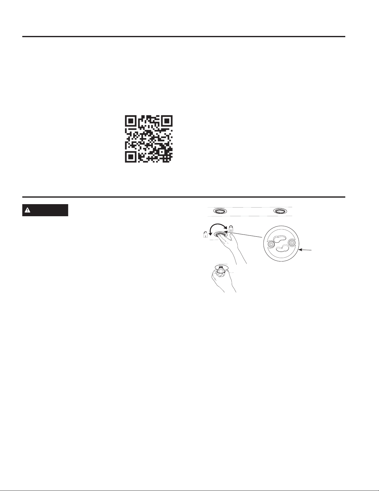
1. Before attempting to replace the lights, make sure that
the light switch is turned off.
2. Rotate light counterclockwise to unlock and pull out.
Wearing latex gloves may offer a better grip.
3. Replace with new light of same type, making sure
pins are inserted properly into the sockets of the lamp
holder and turn clockwise to lock.
All lamps need to be GU10 compatible.
Allow lights to cool before touching.
Lamp
Holder
Rotate the lamp until the
pins are located in narrow
neck of the socket to lock.
49-2000895 Rev. 1 7
Page 8

Installation
Wall Hoods
UVW8301, UVW8361
Instructions
“If you have questions, call GE Appliances at 800.GE.CARES (800.432.2737)
or visit our website at: GEAppliances.com or call 800.561.3344.
BEFORE YOU BEGIN
Read these instructions completely and
carefully.
Ŷ
IMPORTANT — Save these
instructions for local inspector’s use.
Ŷ
IMPORTANT — Observe all governing
codes and ordinances.
Ŷ
Note to Installer – Be sure to leave these
instructions with the Consumer.
Ŷ
INSTALLATION INSTRUCTIONS
Note to Consumer – Keep these instructions for
future reference.
Ŷ
Skill level – Installation of this vent hood requires
basic mechanical and electrical skills.
Ŷ
Completion time – Approximately 1 to 3 hours
Ŷ
Proper installation is the responsibility of the
installer.
Ŷ
Product failure due to improper installation is not
covered under the Warranty.
CAUTION
these vent hoods and to reduce the risk of personal
injury or damage to the product, TWO PEOPLE
ARE REQUIRED FOR PROPER INSTALLATION.
Due to the weight and size of
WARNING
ELECTRIC SHOCK OR INJURY TO PERSONS,
OBSERVE THE FOLLOWING:
A. Installation work and electrical wiring must be
done by qualified person(s) in accordance with
all applicable codes and standards, including
fire-rated construction.
B. Sufficient air is needed for proper combustion
and exhausting of gases through the flue
(chimney) of fuel burning equipment to prevent
back drafting. Follow the heating equipment
manufacturer’s guidelines and safety standards
such as those published by the National Fire
Protection Association (NFPA), the American
Society for Heating, Refrigeration and Air
Conditioning Engineers (ASHRAE) and the local
code authorities.
C. When cutting or drilling into wall or ceiling, do
not damage electrical wiring and other hidden
utilities.
D. Ducted fans must always be vented to the
outdoors.
E. Turn off breaker to adjacent rooms while
working.
WARNING
USE ONLY METAL DUCT WORK.
TO REDUCE THE RISK OF FIRE,
TO REDUCE THE RISK OF FIRE,
FOR YOUR SAFETY
WARNING
switch power off at service panel and lock the
service disconnecting means to prevent power from
being switched on accidentally. When the service
disconnecting means cannot be locked, securely
fasten a prominent warning device, such as a tag,
to the service panel.
Before beginning the installation,
WARNING
at the main circuit breaker or fuse box before
installing.
Disconnect all electrical power
8 49-2000895 Rev. 1
Page 9
Installation Preparation
INSTALLATION PREPARATION
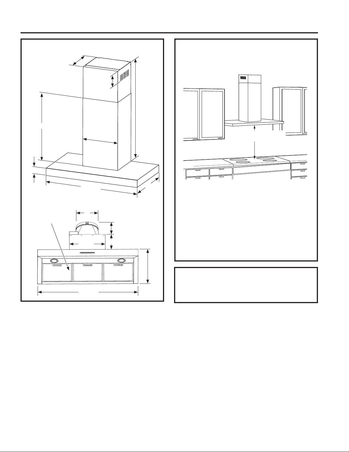
PRODUCT DIMENSIONS
12-1/4Ǝ
4-5/8Ǝ
25-3/4Ǝ
13-13/16Ǝ
2-3/4Ǝ
30ƎRUƎ
Grease Filters
(quantity may vary
by model)
8Ǝ
12-7/8Ǝ
10-5/8Ǝ
6-15/16Ǝ
26-5/8Ǝ min. - 39-1/8Ǝ max.
20Ǝ
20Ǝ
INSTALLATION CLEARANCES
These vent hoods are designed to be installed onto
a wall with no above cabinets.
24” Required Min.
36” Recommended Max.
The vent hood must be installed between the 24”
required minimum and 36” recommended maximum
above the cooking surface. For supplied duct cover
ceiling heights, see Installation Height Table.
NOTE: Installation height should be measured from
the cooking surface to the lowest part of the hood.
The hood must be installed onto a wall. It can be
vented to the outdoors, or it can be installed for
recirculating operation. For recirculation operation,
see Recirculation Install Planning.
Installation instructions, describing the intended
mounting and wiring of the range hood cord
30ƎRUƎ
connection kit, shall be provided with each range
hood cord connection kit.
1" = 2.5 cm
49-2000895 Rev. 1 9
Page 10
Installation Preparation
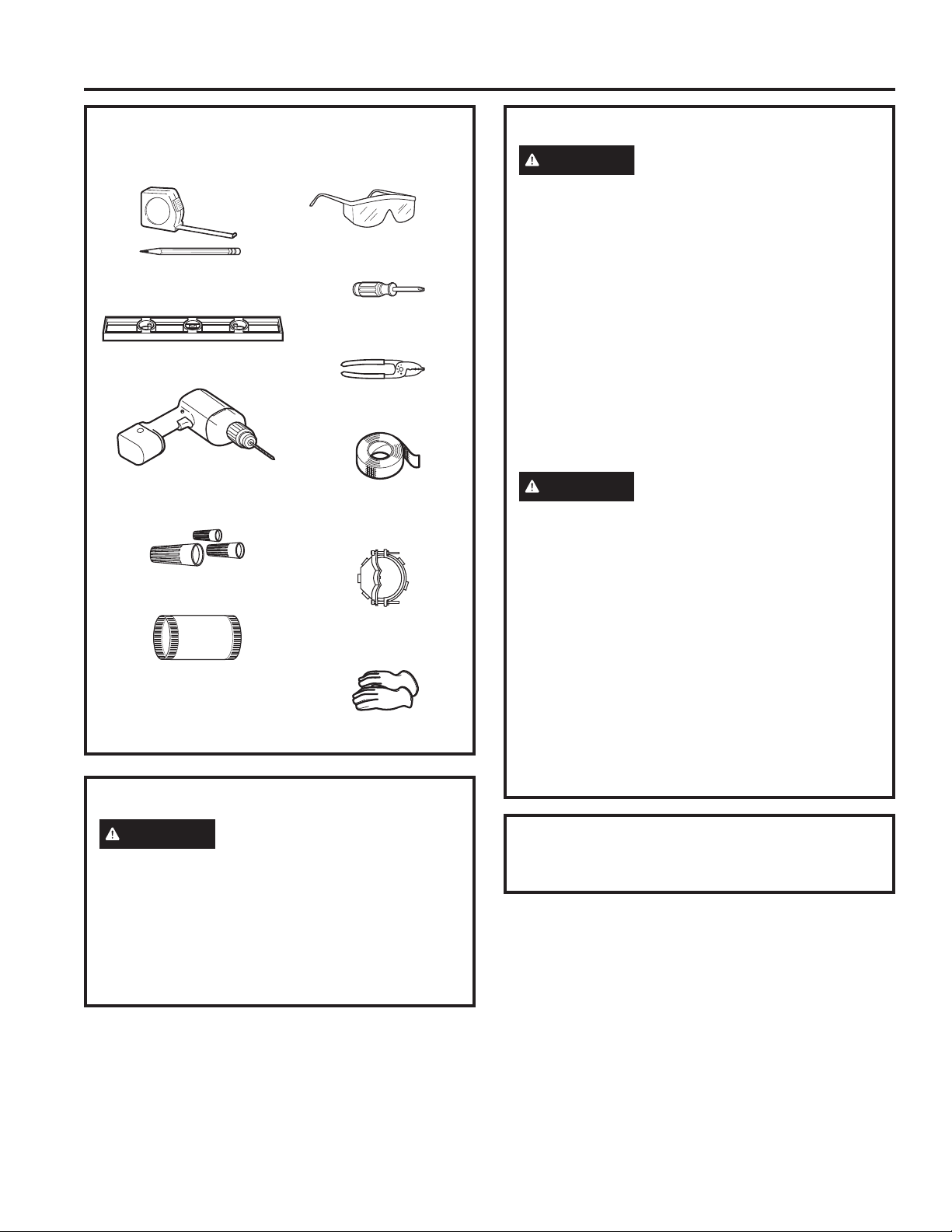
TOOLS AND MATERIALS
REQUIRED (NOT SUPPLIED)
Safety glasses
Pencil and tape measure
Phillips screwdriver
Level
Wire cutter/stripper
Electric drill with #2 Phillips
and 1/8" drill bits
INSTALLATION PREPARATION
UL listed wire nuts
8" round duct
(length will vary)
Aluminized
duct tape
Strain relief for
junction box
Gloves
REMOVE THE PACKAGING
PLAN THE INSTALLATION
CAUTION
properly exhaust air, be sure to duct the air outside.
Do not vent exhaust air into spaces within walls or
ceilings or into attics, crawl spaces, or garages.
PARTS SUPPLIED FOR INSTALLATION
Ŷ 1 Hardware Package
Ŷ 1 Literature Package
Ŷ Recirculation Duct (for recirculation install only)
Ŷ Charcoal filters (recirculation mode)
PARTS NEEDED FOR INSTALLATION
Ŷ 1 Strain Relief
Ŷ 1 Wall or Roof Cap (for ducted venting only)
Ŷ All Metal Ductwork (for ducted venting only)
WARNING
PERSONAL INJURY HAZARD
Because of the weight and size of the rangehood
canopy. It is recommended that 2 people are used
to install the range hood. Failure to properly lift
rangehood could result in damage to the product or
personal injury.
NOTE: This rangehood can be installed as either
ducted or recirculation. In a ducted application,
this rangehood can be vented through the wall
or ceiling. When installed for recirculation, the
rangehood vents out the sides of the duct cover.
NOTE: Before making any cuts or holes for
installation, determine which venting method will be
used and carefully calculate all measurements.
To reduce risk of fire and to
CAUTION
sharp edges.
Ŷ Remove the duct covers.
Ŷ Remove the hardware bag, literature package
and other boxed parts.
Ŷ Remove and properly discard the protective
plastic wrapping and other packaging materials.
Wear gloves to protect against
Use only with range hood cord connection kits that
have been investigated and found acceptable for
use with this model range hood.
1" = 2.5 cm
10 49-2000895 Rev. 1
Page 11
Installation Preparation
INSTALLATION PREPARATION
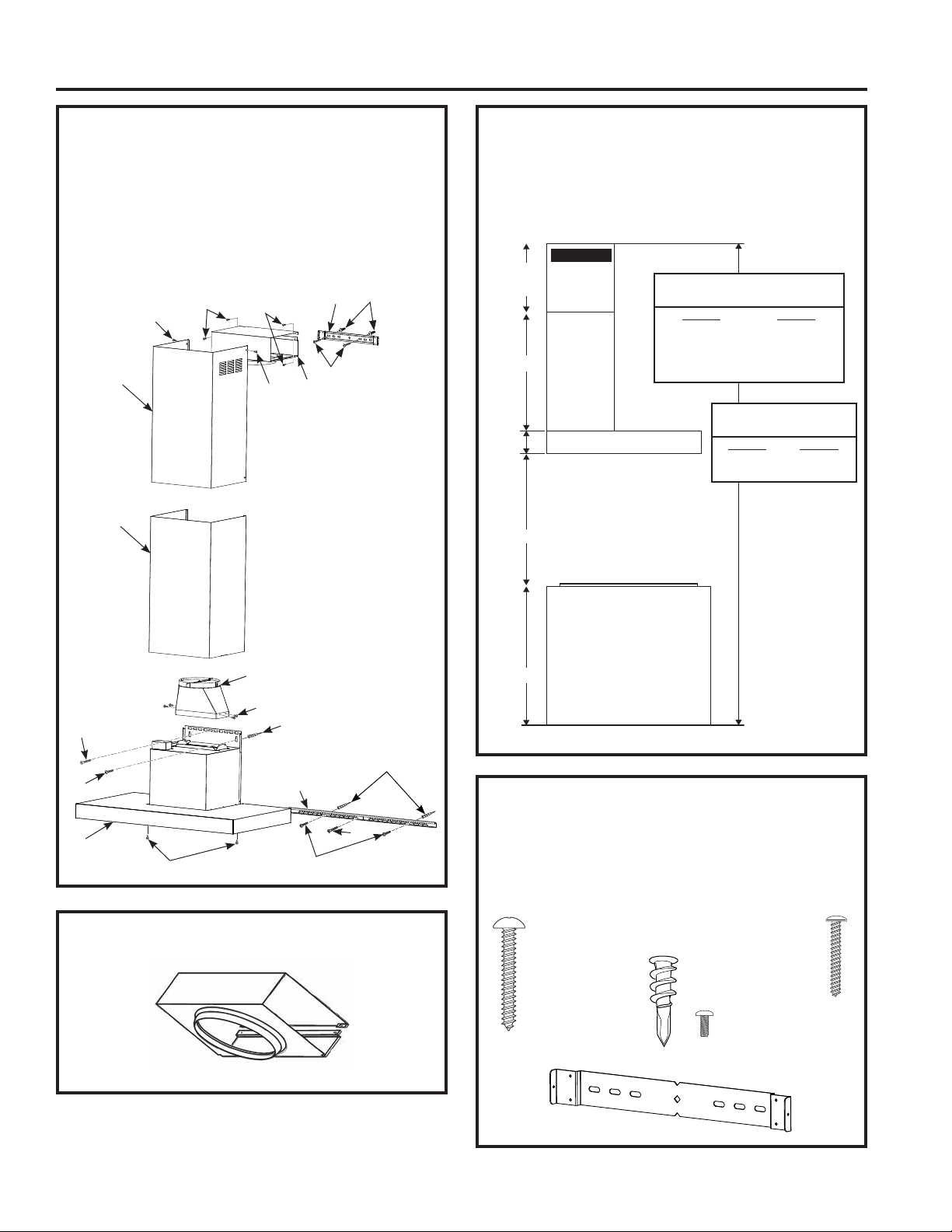
RANGE HOOD COMPONENTS
A. Wall Hood
B. Upper Duct Cover
C. Lower Duct Cover
D. Mounting Screws
E. Duct Cover
Mounting Bracket
F. Damper
J
J
B
C
L
G. Hood Mounting
Bracket
H. Mounting Anchors
J. Machine Screws
K. Recirculation Box
L. Wood Screws
J
J
F
J
H
E
D
K
INSTALLATION DIMENSIONS
The Wall Hoods duct covers can be adjusted for
different ceiling heights depending on the distance
between the bottom of the hood and the cooktop
(distance X). See Installation Height Table.
Upper Duct
7/8Ǝ min
H
13-3/8Ǝ max
25-3/4Ǝ
2-3/4Ǝ
X
36”
X = Distance From Hood To
(Varies depending on installation)
Recommended Max - 36”
manufacturer’s recommendation
Cover
Required Min & Recommended
Max Ceiling Height Examples
Lower
Duct Cover
Hood Body
Cooktop
Required Min - 24”,
Also consult cooktop
Typical Range
X = 24" X = 36"
Min Min
7' 6" 8' 6"
Max Max
8' 6" 9' 5"
Required Min Ceiling
Height for Recirculation
X = 24" X = 36"
Min Min
7' 10" 8' 10"
For higher ceiling
installations up to
10', use the 10' High
Ceiling Duct Cover
kit (UX10DC83) for
your model.
For higher ceiling
installations up to
12', use the 12' High
Ceiling Duct Cover
kit (UX12DC93) for
your model.
For higher ceiling
installations up to
14', use the 14' High
Ceiling Duct Cover
kit (UX14DC93) for
your model.
H
D
G
HARDWARE COMPONENTS
A
J
L
D
RECIRCULATION COMPONENTS
K
49-2000895 Rev. 1 11
NOTE: The chimney extension replaces the upper
and lower chimney shipped with the range hood.
The hardware included with the hood should be
saved and also used with the chimney extension.
L
Phillips Head
Wood Screw
3/16" x 1-15/16"
(QTY: 4)
Mounting Anchors
H
(QTY: 6)
E
Phillips Head
Mounting Anchors
Screws
3/16" x 1-1/2"
(QTY: 6)
J
Phillips Head
Machine Screw
1/8" x 3/8"
(QTY: 14)
1' = 0.3 m, 1" = 2.5 cm
D
Page 12
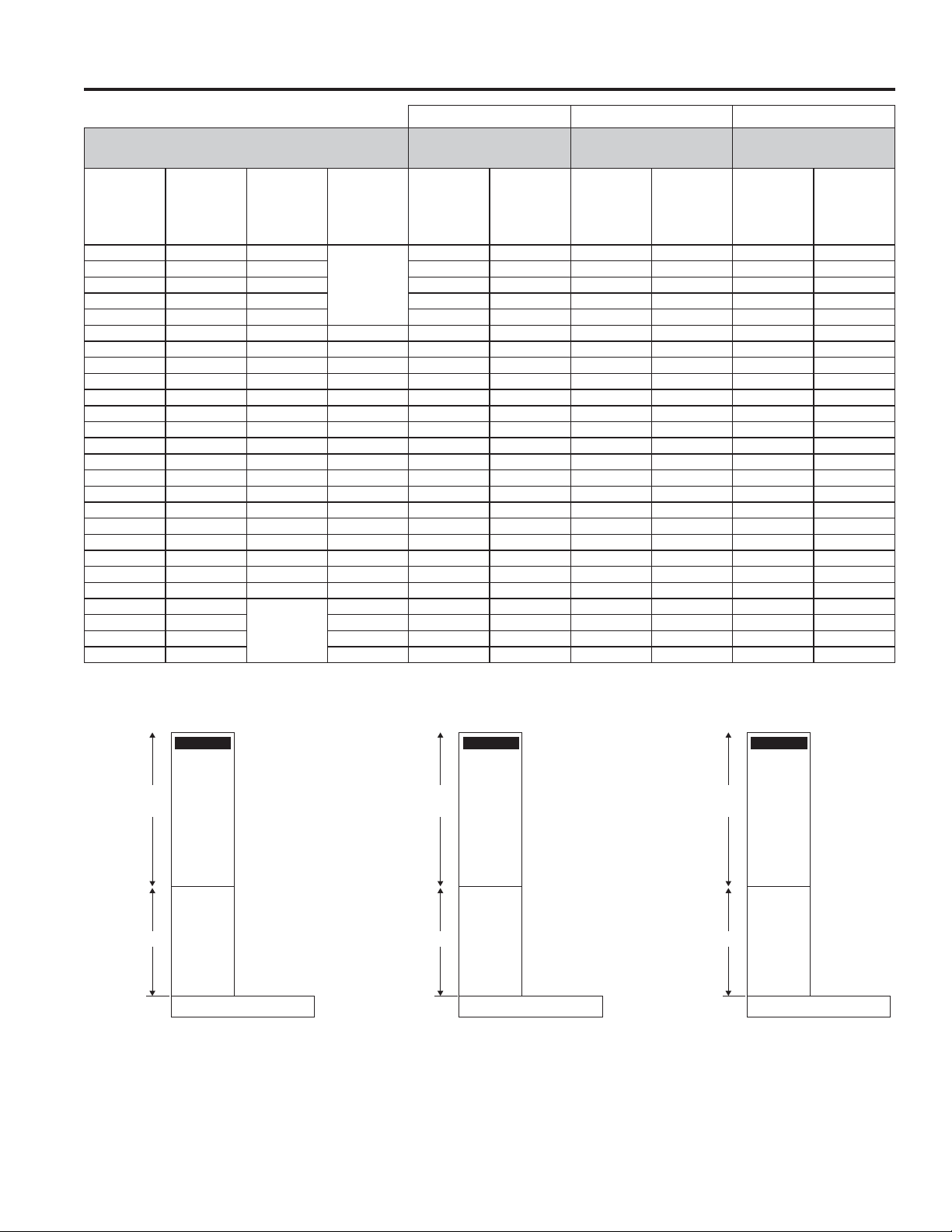
Installation Preparation
INSTALLATION HEIGHT TABLE (UX10DC8SLSS) (UX12DC9SLSS) (UX14DC9SLSS)
Optional High Ceiling Duct
Installation Height with Supplied Duct Covers
Possible
Vented
Ceiling
Height (ft./in.)
7' 6" 24 24 7' 7" 24-25 9' 4" 24-25 12' 24-36
7' 7" 24-25 24-25 7' 8" 24-26 9' 5" 24-26 12' 1" 24-36
7' 8" 24-26 24-26 7' 9" 24-27 9' 6" 24-27 12' 2" 24-36
7' 9" 24-27 24-27 7' 10" 24-28 9' 7" 24-28 12' 3" 24-36
7' 10" 24-28 24-28 24 7' 11" 24-29 9' 8" 24-29 12' 4" 24-36
7' 11" 24-29 24-29 24-25 8' 24-30 9' 9" 24-30 12' 5" 24-36
8' 24-30 24-30 24-26 8' 1" 24-31 9' 10" 24-31 12' 6" 24-36
8' 1" 24-31 24-31 24-27 8' 2" 24-32 9' 11" 24-32 12' 7" 24-36
8' 2" 24-32 24-32 24-28 8' 3" 24-33 10' 24-33 12' 8" 24-36
8' 3" 24-33 25-33 24-29 8' 4" 24-34 10' 1" 24-34 12' 9" 24-36
8' 4" 24-34 26-34 24-30 8' 5" 24-35 10' 2" 24-35 12' 10" 24-36
8' 5" 24-35 27-35 24-31 8' 6"- 9' 5" 24-36 10'3"-11' 24-36 12' 11" 24-36
8' 6" 25-36 28-36 25-32 9' 6" 25-36 11' 1" 24-36 13' 24-36
8' 7" 26-36 29-36 26-33 9' 7" 26-36 11' 2" 24-36 13' 1" 25-36
8' 8" 27-36 30-36 27-34 9' 8" 27-36 11' 3" 24-36 13' 2" 26-36
INSTALLATION PREPARATION
8' 9" 28-36 31-36 28-35 9' 9" 28-36 11' 4" 24-36 13' 3" 27-36
8' 10" 29-36 32-36 29-36 9' 10" 29-36 11' 5" 24-36 13' 4" 28-36
8' 11" 30-36 33-36 30-36 9' 11" 30-36 11' 6" 24-36 13' 5" 29-36
9' 31-36 34-36 31-36 10' 31-36 11' 7" 24-36 13' 6" 30-36
9' 1" 32-36 35-36 32-36 10' 1" 32-36 11' 8" 25-36 13' 7" 31-36
9' 2" 33-36 36 33-36 10' 2" 33-36 11' 9" 26-36 13' 8" 32-36
9' 3" 34-36 34-36 10' 3" 34-36 11' 10" 27-36 13' 9" 33-36
9' 4" 35-36 35-36 10' 4" 35-36 11' 11" 28-36 13' 10" 34-36
9' 5" 36 36 10' 5" 36 12' 29-36 13' 11" 35-36
Possible
Vented Install
Height (in.)
Install Height
(Recirculation
Vented Holes
Hidden) (in.)
For gas range, start chart at 92" and subtract 2" for the maximum install height for each block.
Possible
Recirculation
Install
Height (in.)
Cover up to 10 ft.
(not included with unit)
Ceiling
Height (ft./in.)
7' 6" 24 9' 3" 24 11' 11" 24-36
*Based on a 36" electric range height.
Vented and
Recirculation
Height (in.)
Optional High Ceiling Duct
Cover up to 12 ft.
(not included with unit)
Vented and
Ceiling
Height (ft./in.)
Recirculation
Install
Height (in.)
Optional High Ceiling Duct
Cover up to 14 ft.
(not included with unit)
Ceiling
Height (ft./in.)
14" 36
Vented and
Recirculation
Install
Height (in.)
7/8Ǝ min
25-1/8Ǝ max
25-3/4"
Hood Body
10" High Ceiling Duct Cover Kit
Upper
Duct Cover
Lower
Duct Cover
7/8Ǝ min
29-7/16" max
46-7/8"
Hood Body
12" High Ceiling Duct Cover Kit
Upper
Duct Cover
Lower
Duct Cover
Upper
Duct Cover
7/8Ǝ min
46-1/4" max
46-7/8"
Lower
Duct Cover
Hood Body
14" High Ceiling Duct Cover Kit
1' = 0.3 m, 1" = 2.5 cm
12 49-2000895 Rev. 1
Page 13
Installation Preparation
INSTALLATION PREPARATION
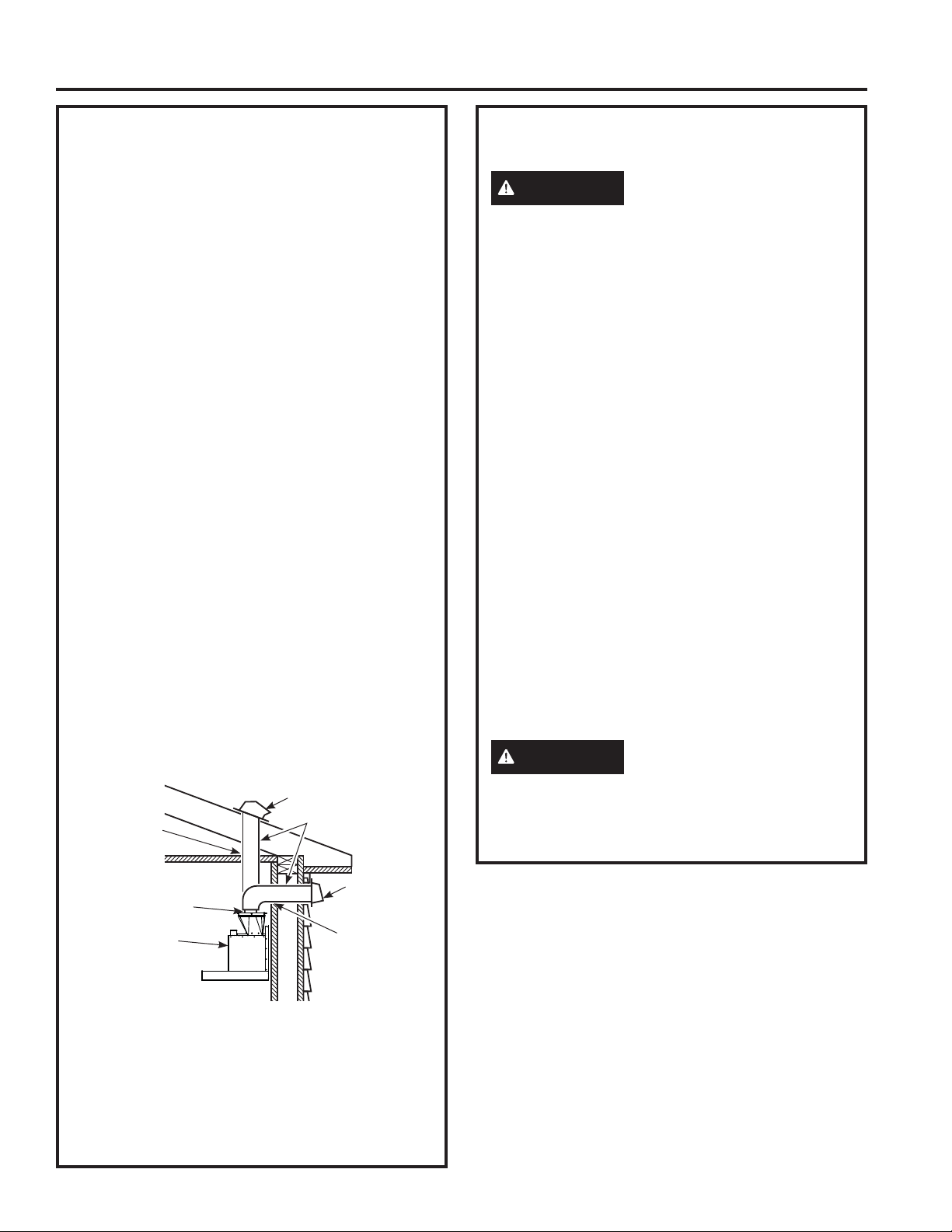
ADVANCE PLANNING
Duct Install Planning
Ŷ This hood is designed to be vented vertically
through the ceiling. Use an 8" round duct. Use
locally supplied elbows to vent horizontally
through the rear wall.
Ŷ Use metal ductwork only.
Ŷ Determine the exact location of the vent hood.
Ŷ Plan the route for venting exhaust to the
outdoors. To maximize the ventilation
performance of the vent system:
1. Minimize the duct run length and number of
transitions and elbows.
2. Maintain a constant duct size.
3. Seal all joints with duct tape to prevent any leaks.
NOTE: Flexible vent is not recommended. Flexible
vent creates back pressure and air turbulence that
greatly reduces performance.
Ŷ Maximum equivalent duct length for 100 CFM:
150 foot for vent hoods.
Ŷ Install a wall cap or roof cap with damper at the
exterior opening. Purchase the wall or roof cap
and any transition and length of duct needed in
advance.
Ŷ
When applicable, install any makeup (replacement)
air system in accordance with local building code
requirements. Use makeup air kit JXMUA8.
Vent system can terminate either through the roof
RUWKHZDOO7RYHQWWKURXJKDZDOODHOERZLV
needed and installed immediately above the hood.
Roof Cap
Add Insulation
and/or Caulk
Round Duct
POWER SUPPLY
IMPORTANT – (Please read carefully)
WARNING
FOR PERSONAL SAFETY, THIS APPLIANCE
MUST BE PROPERLY GROUNDED.
Remove house fuse or open circuit breaker before
beginning installation.
Do not use an extension cord or adapter plug with
this appliance. Follow National Electrical Codes or
prevailing local codes and ordinances.
Electrical supply
These vent hoods must be supplied with 120V,
60Hz, and connected to an individual, properly
grounded branch circuit, and protected by a 15 or
20 amp circuit breaker or time delay fuse.
Ŷ Wiring must be 2 wire with ground.
Ŷ If the electrical supply does not meet the above
requirements, call a licensed electrician before
proceeding.
Ŷ Route house wiring as close to the installation
location as possible in the ceiling or wall.
Ŷ Connect the wiring to the house wiring in
accordance with local codes.
Grounding instructions
The grounding conductor must be connected to
a ground metal, permanent wiring system, or an
equipment-grounding terminal or lead on the hood.
WARNING
equipment-grounding conductor can result in a risk
of electric shock. Check with a qualified electrician
or service representative if you are in doubt whether
the appliance is properly grounded.
The improper connection of the
Wall Cap
Add tape to joint
Hood
Recirculation Install Planning
A recirculation duct (included) and charcoal
filter (included) are necessary for recirculation
installation.
Power Supply Planning
The location of the power supply connection is called
out in the Installing The Hood Bracket Mount section.
49-2000895 Rev. 1 13
Add Insulation
and/or Caulk
1" = 2.5 cm
Page 14
Installation
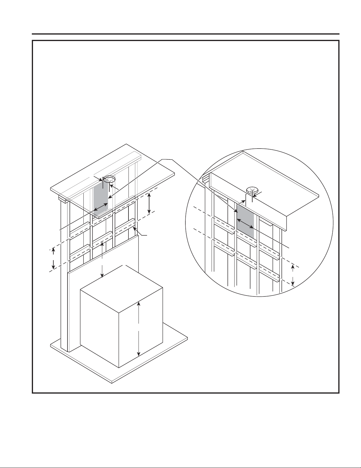
NEW CONSTRUCTION, PRE-PLANNING, OR REMODELING
NOTE: For existing construction, skip to the section, Installing The Hood Bracket Mount.
Ŷ Install horizontal wood supports between 2 wall
studs that align with the vertical mounting height
locations shown in the illustration.
Ŷ The horizontal supports must be flush with the room
INSTALLATION
side studs.
Ŷ For ducted installation, the hole for the duct in the
ceiling must be centered 5" away from the finished
rear wall.
5"
From the lower left corner of
the gray shaded area, it is
recommended to have at least
20" of house electrical wiring.
Ŷ The bottom support aligns with the hood mounting
bracket. This height depends on the desired height
of the hood.
Ŷ The top support must be flush with the ceiling.
Ŷ The electrical wiring can be located 5-1/2” to the left
or right (junction box is on the left) of the centerline.
Must remain 7/16” above the back panel and 5” from
the ceiling, refer to illustration on next page.
5"
Acceptable
area for
electrical
wiring
14-3/8"
11"
24-36" + 1-1/8"
See the Installation
Height Table for possible
installation heights.
* 36” or 38” Range
Wood Supports
• 36" minimum
width centered
• 4" height
* Typical electrical range is 36"
and typical gas range is 38"
11"
Acceptable
area for
electrical
wiring
14-3/8"
1" = 2.5 cm
14 49-2000895 Rev. 1
Page 15
Installation
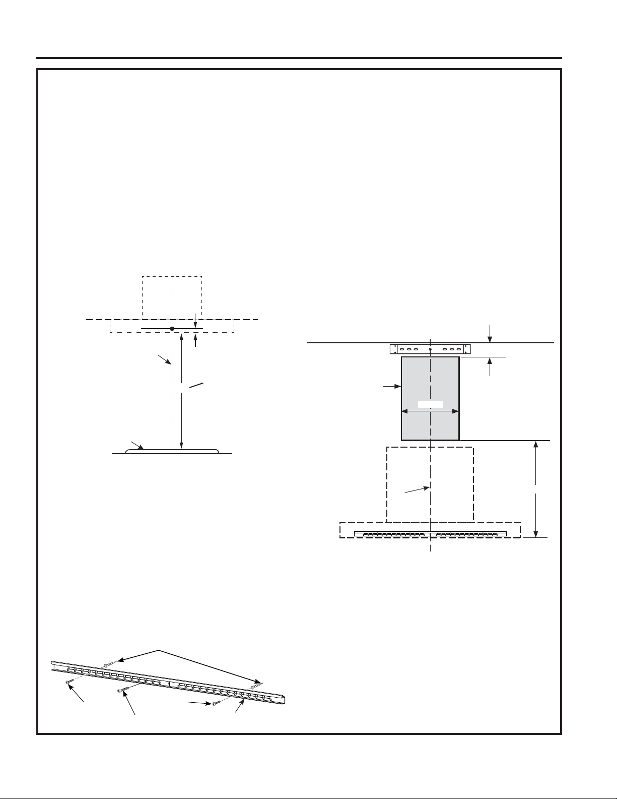
INSTALLING THE HOOD BRACKET MOUNT
Hood Body
1. Put a protective covering over the surface
below the location of the hood to protect from
dirt and/or damage.
2. Determine and mark the centerline (C) on the
wall (draw line up to the ceiling) where the range
hood will be installed. Based on the ceiling height,
determine the distance between 24” required
min, 36” recommended max (X) needed between
the cooking surface (B) and the bottom of the
hood. Draw a horizontal line at X. Align the install
template so that the bottom of the template is
centered and is level with the horizontal line drawn
at height X.
Duct Covers and Power Supply
1. Place the duct cover bracket (E) on the wall so that
its edge is against the ceiling and level, making
sure the slots are in direct contact with the wall.
Align the center notches of the bracket and the
centerline. Mark the location of the screw holes
furthest apart from the center line if possible. If one
of the screw holes aligns with a stud, then a wood
screw will be used for that location. For the other
hole or if there are no studs, install 2 mounting
anchors (H). Place the duct cover bracket (E)
on the wall and install with wood screws (L) and
mounting screws (D) as needed.
2. The house electrical wiring must fall in the gray
shaded area shown below. From the lower left
corner of the shaded area, a minimum of 20” of
house electrical wiring is recommended to reach
the electrical junction box on the hood.
INSTALLATION
C
B
1-1/8"
24 to 36"
X
3. Find the stud locations and mark them on the
template.
4. Place the hood mounting bracket (G) on its outline
on the template. Mark at least one wood screw (L)
location that is on a stud. If another stud cannot be
found, mark at least two other screw locations for
mounting anchors, one on each side of the wood
screw (L). Remove the bracket from the wall and
install the mounting anchors (H). Place the hood
mounting bracket (G) back on the wall and mount it
with the wood screws (L) and mounting screws (D)
as needed. It is recommended to create a pilot hole
in the studs for wood screws (L).
Ceiling
area for house
Acceptable
electrical
wiring
Ǝ%HORZ&HLOLQJ
Ǝ
C
16-7/8"
Mounting
Anchors
Mounting
Screw
Wood Screw
Mounting
Screw
Hood Mounting Bracket
1" = 2.5 cm
49-2000895 Rev. 1 15
Page 16
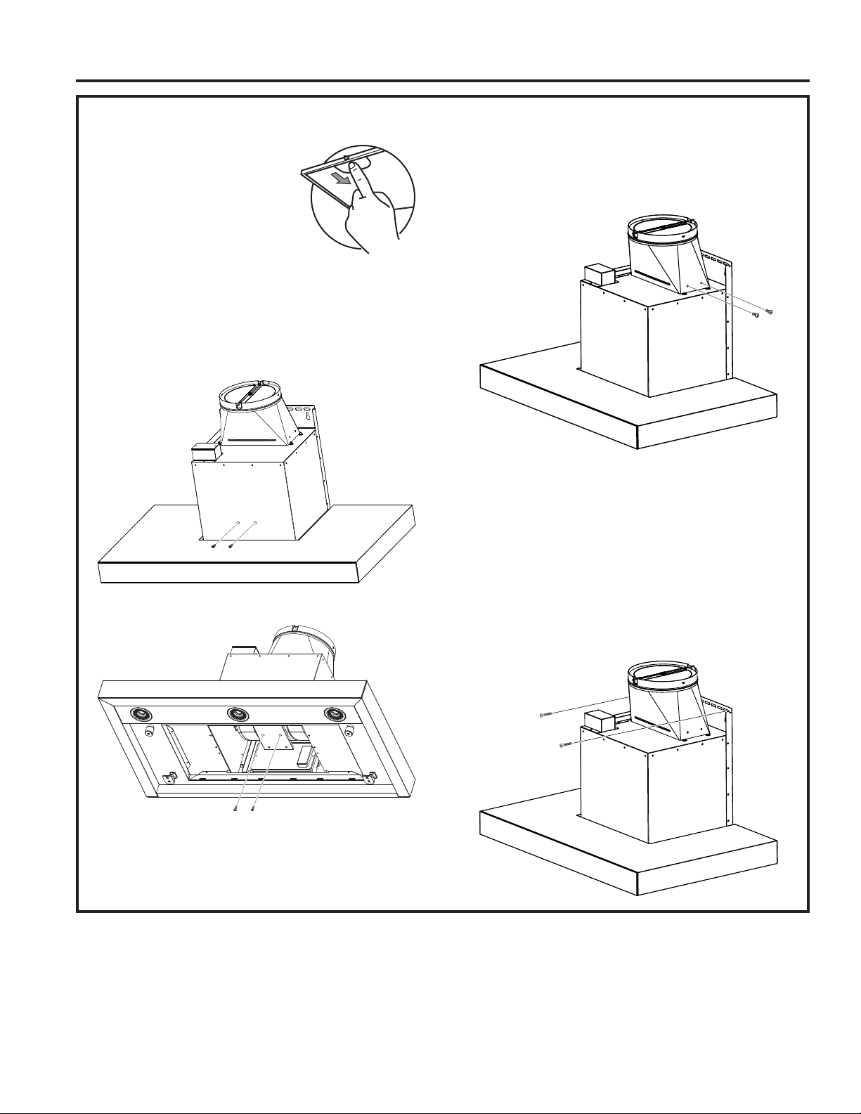
INSTALLING THE HOOD
Remove the grease filters from
the unit and set aside. The
grease filters are removed by
pressing the handle in the front
of the filter. When replacing,
make sure that the filters are
properly positioned with the
INSTALLATION
handles in front and visible.
NOTE: On some models, the front panel covers the
filters and must be pulled down to access the filters.
NOTE: This bracket must be removed prior to
installation. Remove 2 front and 2 bottom screws per
illustration bellow.
Installation
1. Securely press the damper on top of the exhaust
opening. Check that the damper opens freely.
Attach damper to hood using machine screws
(J) provided.
2. Remove and properly discard the protective plastic
wrapping from the hood and grease filter. Remove
the template off the wall.
3. Mount the Range Hood:
Ŷ Using 2 or more people, lift the range hood and
place on the hood mounting bracket. Make sure
the bracket fully engages the hood body.
Ŷ Install the 2 mounting screws (D) or wood screws
(L) as needed into the designated holes on the
back panel.
16 49-2000895 Rev. 1
Page 17
Installation
INSTALLATION
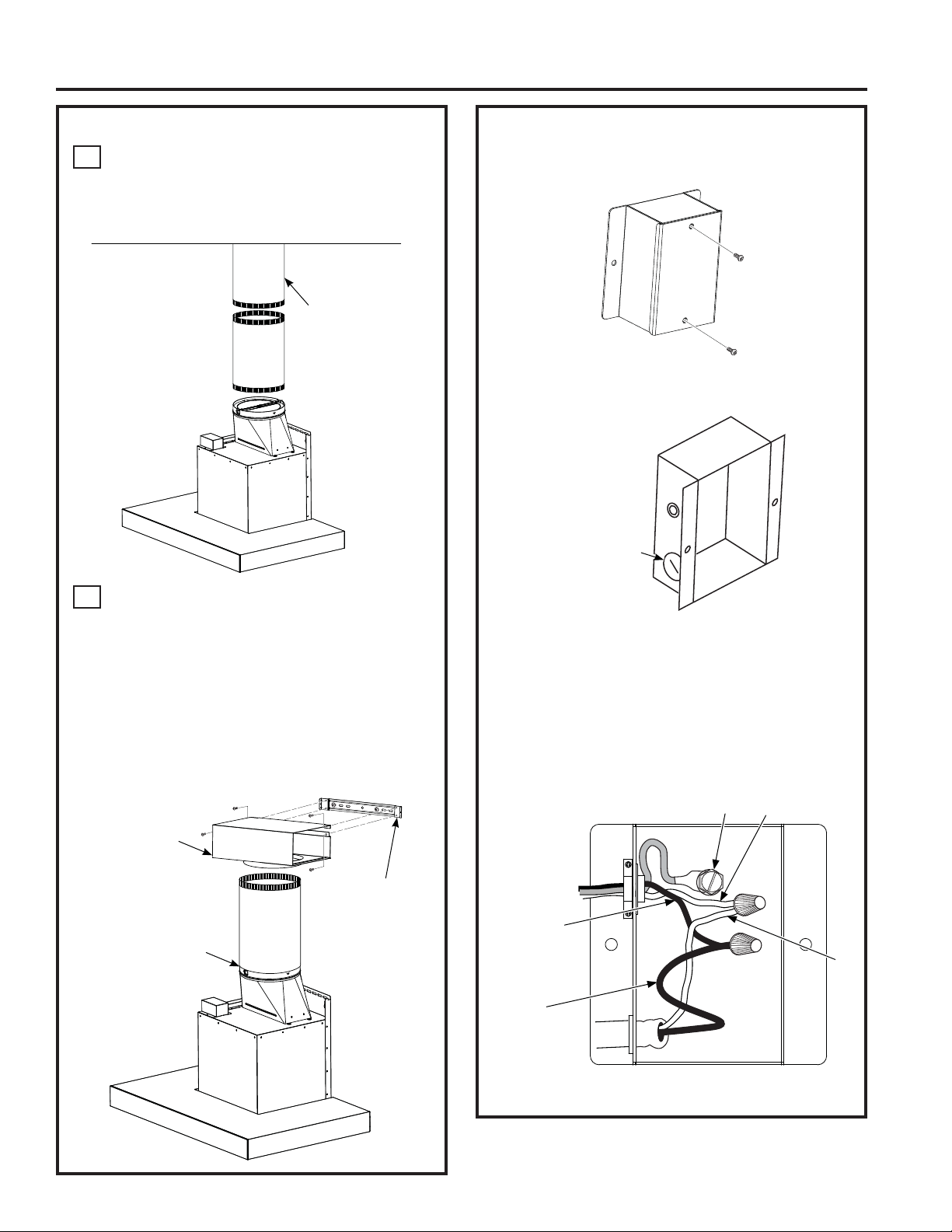
INSTALLING THE HOOD (Cont.)
A
Vented Installations
Connect the house ducting to the damper on the
hood body. Seal all connections with duct tape
(Do not use screws).
Ceiling
House
Ducting
ELECTRICAL CONNECTION
1. Remove the electrical junction box cover.
2. Remove the electrical box knockout.
Electrical Box
Knockout with
Strain Relief
B
Recirculation (Non-vented)
NOTE: A recirculation box, a charcoal filter, and a
bracket are included with the hood and are necessary
for recirculation installation.
1. Attach the recirculation box to the duct over
mounting bracket with 4 machine screws (J).
2.
Connect the ducting from the exhaust outlet on
the hood to the recirculation box. Use duct tape
to seal the connections on the recirculation box
and the exhaust outlet.
Recirculation Box
Duct Cover
Mounting
(Do not use screws)
Use tape
Bracket
3. Feed the Power Supply Cable through the hole
and secure with a strain relief.
4. Attach the white lead of the power supply (A) to
the white lead of the range hood (D) with a wire
nut. Attach the black lead of the power supply (B)
to the black lead of the range hood (C) with a wire
nut. Connect the house ground wire under the
green grounding screw (E).
E
A
House Wiring
B
C
Hood Wiring
D
5. Reattach the electrical junction box cover.
49-2000895 Rev. 1 17
Page 18
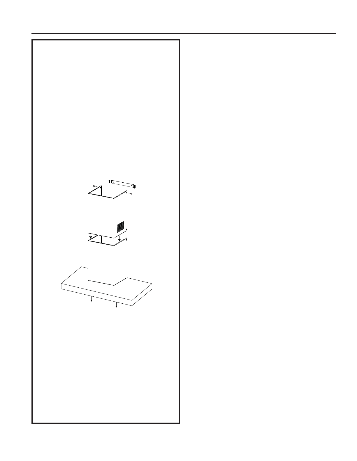
INSTALL DUCT COVERS
1. For ducted and recirculation installation:
Remove protective film from duct covers. Place
the upper duct cover so that it slides down inside
of the lower duct cover.
NOTE: For recirculation, the upper duct cover
must be installed with the exhaust vents on the
INSTALLATION
top towards the ceiling.
Depending on the amount of overlap between
the top and bottom duct covers, the top may be
reversed to hide vent holes. Refer to Installation
Height Table for possible heights.
Place the set of duct covers by sitting them
down to fit securely on top of the hood. Finish
attaching the lower duct cover to the body of the
hood with two machine screws (J) that screw
from up underneath the hood.
Installation
2. Install the upper duct cover by carefully raising
it up to avoid scratching until it reaches the
ceiling. Push the duct cover flush against the
wall, then use two machine screws (J) to mount
the upper duct to the duct mounting bracket.
3. If recirculating, install the charcoal filters. Then
reinstall the grease filters to the hood, see the
Filters section.
4. Turn the power supply on. Turn on the blower
and light. If the range hood does not operate,
check that the circuit breaker is not tripped or the
house fuse blown. If the unit still does not operate,
disconnect the power supply and check that the
wiring connections have been made properly.
18 49-2000895 Rev. 1
Page 19
Troubleshooting tips ... Before you call for service
Save time and money! Review the charts on the following pages first and you may not need to call for service.
Problem Possible Cause What To Do
Fan/Light does not
operate when button is
turned ON
Loud or abnormal
airflow noise
Fan fails to circulate
air or moves air slower
than normal and/or
fan is making loud or
abnormal airflow noise
Early light failure Light wattage is too high. Replace with correct wattage.
Fan keeps going off
and on
A house fuse may be blown or a circuit
breaker tripped.
Wrong duct size used in installation. This hood requires 8” ducting to perform optimally.
Obstructions in duct work. Make sure nothing is blocking the vent. Make sure
Damper blade on wall or roof cap may
not be open.
Metal grease filter and charcoal filter (if
present) may be dirty.
Insufficient makeup (replacement) air Sufficient makeup (replacement) air is required for
The motor is probably overheating and
turning itself off. This can be harmful to
the motor.
Replace fuse or reset circuit breaker.
Using smaller duct pipe will cause reduced venting.
Minimize the duct run length and number of transitions
and elbows. GE Appliances service technicians cannot
correct this issue if installed improperly.
your wall or roof cap has a blade or door.
Make sure damper swings freely. Damper blades may
flip over and will not fully open when this happens.
Adjust to original position.
Clean the metal grease filter and replace charcoal filter
(if present). See Care and Cleaning of the Vent Hood.
exhausting appliances to operate to rating. Check with
local building codes, which may require or strongly
advise the use of makeup air. Visit GEAppliances.com
for available makeup air solutions.
Check to be sure the filters are clean. If off and on
cycling continues, call for service.
TROUBLESHOOTING TIPS
49-2000895 Rev. 1 19
Page 20

Notes
20 49-2000895 Rev. 1
Page 21

Notes
49-2000895 Rev. 1 21
Page 22
GE Appliances Vented Range Hood Limited Warranty
GEAppliances.com
All warranty service is provided by our Factory Service Centers, or an authorized Customer Care® technician. To
schedule service online, visit us at geappliances.com/service_and_support/, or call GE Appliances at 800.GE.CARES
(800.432.2737). In Canada, visit GEAppliances.ca/en/support/service-request or call 800.561.3344. Please have your
serial number and your model number available when calling for service.
Servicing your appliance may require the use of the onboard data port for diagnostics. This gives a GE Appliances factory
service technician the ability to quickly diagnose any issues with your appliance and helps GE Appliances improve its
products by providing GE Appliances with information on your appliance. If you do not want your appliance data to be
sent to GE Appliances, please advise your technician not to submit the data to GE Appliances at the time of service.
For the period of GE Appliances will replace
One year
From the date
of the original
LIMITED WARRANTY
purchase
What GE Appliances will not cover:
Ŷ Service trips to your home to teach you how to use
the product.
Ŷ Improper installation, delivery, or maintenance.
Ŷ Failure of the product if it is abused, misused,
modified, or used for other than the intended purpose
or used commercially.
Ŷ Replacement of house fuses or resetting of circuit
breakers.
Ŷ Damage to the product caused by accident, fire,
floods, or acts of God.
Any part of the cooking product which fails due to a defect in materials or workmanship.
During this limited one-year warranty, GE Appliances will provide, free of charge, all labor
and related service costs to replace the defective part.
Ŷ Damage to finish, such as surface rust, tarnish, or small
blemishes not reported within 48 hours of delivery.
Ŷ Incidental or consequential damage caused by
possible defects with this appliance.
Ŷ Damage caused after delivery.
Ŷ Product not accessible to provide required service.
Ŷ Service to repair or replace light bulbs, except for LED
lamps.
EXCLUSION OF IMPLIED WARRANTIES
Your sole and exclusive remedy is product repair as provided in this Limited Warranty. Any implied warranties,
including the implied warranties of merchantability or fitness for a particular purpose, are limited to one year or
the shortest period allowed by law.
This limited warranty is extended to the original purchaser and any succeeding owner for products purchased for home
use within the USA. If the product is located in an area where service by a GE Appliances Authorized Servicer is not
available, you may be responsible for a trip charge or you may be required to bring the product to an Authorized GE
Appliances Service location for service. In Alaska, the limited warranty excludes the cost of shipping or service calls to
your home.
warranty gives you specific legal rights, and you may also have other rights which vary from state to state. To know
what your legal rights are, consult your local or state consumer affairs office or your state’s Attorney General.
In Canada: This warranty is extended to the original purchaser and any succeeding owner for products purchased in
Canada for home use within Canada. If the product is located in an area where service by a GE Authorized Servicer
is not available, you may be responsible for a trip charge or you may be required to bring the product to an Authorized
GE Service location. Some provinces do not allow the exclusion or limitation of incidental or consequential damages.
This warranty gives you specific legal rights, and you may also have other rights which vary from province to province.
To know what your legal rights are, consult your local or provincial consumer affairs office.
Garante: GE Appliances, a Haier company Garante en Canadá: MC Commercial
Staple your receipt here. Proof of the original purchase
date is needed to obtain service under the warranty.
Some states do not allow the exclusion or limitation of incidental or consequential damages. This limited
Louisville, KY 40225 Burlington, ON, L7R 5B6
Extended Warranties: Purchase a GE Appliances extended warranty and learn about special discounts that are
available while your warranty is still in effect. You can purchase it online anytime at
In US: geappliances.com/service_and_support/shop-for-extended-service-plans.htm
In Canada: geappliances.ca/en/support/purchase-extended-warranty
or call 800.626.2224 (Canada 866.277.9842) during normal business hours. GE Appliances Service will still be there
after your warranty expires.
22 49-2000895 Rev. 1
Page 23

Accessories
Looking For Something More?
GE Appliances offers a variety of accessories to
improve your cooking and maintenance experiences!
Refer to the Consumer Support page for phone numbers
and website information.
The following products and more are available:
Parts
Power Cord Kit
Make-up Air Kit
Charcoal Filter
Recirculation Kit
Remote Control
10' High Ceiling Duct Cover Kit
12' High Ceiling Duct Cover Kit
14' High Ceiling Duct Cover Kit
Cleaning Supplies
CitruShine™ Stainless Steel Wipes
CERAMA BRYTE
Bar Keepers Friend Soft Cleanser™
®
Stainless Steel Appliance Cleaner
ACCESSORIES
49-2000895 Rev. 1 23
Page 24

Consumer Support
GE Appliances Website
Have a question or need assistance with your appliance? Try the GE Appliances Website 24 hours a day, any day
of the year! You can also shop for more great GE Appliances products and take advantage of all our on-line support
services designed for your convenience. In the US: GEAppliances.com. In Canada: GEAppliances.ca.
Register Your Appliance
Register your new appliance on-line at your convenience! Timely product registration will allow for enhanced
communication and prompt service under the terms of your warranty, should the need arise. You may also mail in
the pre-printed registration card included in the packing material. In the US: GEAppliances.com/register.
In Canada: Prodsupport.mabe.ca/crm/Products/ProductRegistration.aspx
Schedule Service
Expert GE Appliances repair service is only one step away from your door. Get on-line and schedule your service at
CONSUMER SUPPORT
your convenience any day of the year. In the US: GEAppliances.com/service or call 800.432.2737 during normal
business hours. In Canada: GEAppliances.com/en/support/service-request
Extended Warranties
Purchase a GE Appliances extended warranty and learn about special discounts that are available while your
warranty is still in effect. You can purchase it on-line anytime. GE Appliances Services will still be there after your
warranty expires. In the US: GEAppliances.com/extended-warranty or call 800.626.2224 during normal business
hours. In Canada: GEAppliances.com/en/support/purchase-extended-warranty
Remote Connectivity
For assistance with wireless network connectivity (for models with remote enable),
visit our website at GEAppliances.com/connected-home-smart-appliances/ or call 800.220.6899 in the US.
Parts and Accessories
Individuals qualified to service their own appliances can have parts or accessories sent directly to their homes
(VISA, MasterCard and Discover cards are accepted). Order on-line today 24 hours every day.
In the US: GEApplianceparts.com or by phone at 877.959.8688 during normal business hours.
In Canada: GEAppliances.com/en/products/parts-filters-accessories
Instructions contained in this manual cover procedures to be performed by any user. Other servicing
generally should be referred to qualified service personnel. Caution must be exercised, since improper
servicing may cause unsafe operation.
Contact Us
If you are not satisfied with the service you receive from GE Appliances, contact us on our Website with all the
details including your phone number, or write to:
In the US: General Manager, Customer Relations | GE Appliances, Appliance Park | Louisville, KY 40225
GEAppliances.com/contact
In Canada : Director, Consumer Relations, Mabe Canada Inc. | Suite 310, 1 Factory Lane | Moncton, N.B. E1C 9M3
GEAppliances.ca/en/contact-us
Printed in China
24 49-2000895 Rev. 1
Page 25

CONSIGNES DE SÉCURITÉ ..........3
UTILISATION DE LA HOTTE
Commandes ..............................5
Chef Connect .............................5
MANUEL
D’UTILISATION ET
INSTRUCTIONS
D’INSTALLATION
ENTRETIEN ET NETTOYAGE
Filtres ................................... 6
Surfaces ..................................7
Ampoules .................................7
INSTRUCTIONS
D’INSTALLATION ...................8
TRUCS DE DÉPANNAGE ............18
GARANTIE LIMITÉEY .............. 22
ACCESSOIRES ...................... 23
SOUTIEN AU
CONSOMMATEUR .................. 24
UVW8301
UVW8361
Inscrivez ci-dessous les numéros
de modèle et de série
N° de modèle ____________
N° de série ______________
Vous les trouverez sur une
étiquette à l’intérieur de la hotte..
HOTTES MURALES
GE est une marque déposée de General Electric Company. Fabriqué sous licence de marque.
49-2000895 Rev. 1 05-21 GEA
Page 26

NOUS VOUS REMERCIONS D’ACCUEILLIR GE APPLIANCES CHEZ VOUS
Que vous ayez grandi avec GE Appliances ou qu’il s’agisse de votre première acquisition, nous
sommes heureux de vous accueillir dans notre famille.
Nous sommes fiers du savoir-faire, de l’innovation et de l’esthétique qui composent chaque appareil
GE Appliances, et nous pensons que vous le serez aussi. Dans cette optique, nous vous rappelons
que l’enregistrement de votre électroménager vous assure la communication de renseignements
importants sur le produit et la garantie lorsque vous en avez besoin.
Enregistrez votre électroménager GE en ligne dès maintenant. Des sites Web et des numéros de
téléphone utiles figurent dans la section Soutien au consommateur de ce manuel d’utilisation.
Vous pouvez aussi poster la fiche de garantie pré-imprimée incluse dans l’emballage.
2 49-2000895 Rev. 1
Page 27

CONSIGNES DE SÉCURITÉ IMPORTANTES
VEUILLEZ LIRE TOUTES LES CONSIGNES AVANT D’UTILISER
CONSIGNES DE SÉCURITÉ
AVERTISSEMENT
D’INCENDIE, DE CHOC ÉLECTRIQUE OU DE
BLESSURE CORPORELLE, OBSERVEZ LES
DIRECTIVES SUIVANTES :
A. Utilisez cet appareil seulement de la manière
prévue par le fabricant. Si vous avez des questions,
contactez le fabricant.
B. Avant de réparer ou nettoyer l’appareil, coupez le
courant au panneau de distribution électrique et
verrouillez le dispositif de coupure pour éviter tout
rétablissement accidentel du courant. Si vous ne
pouvez pas verrouiller le dispositif de coupure de
courant, attachez soigneusement un avertissement
bien visible, par exemple une étiquette, sur le
panneau de distribution électrique.
C. N’utilisez pas cet appareil avec un régulateur de
vitesse à semi-conducteurs.
D. Cet appareil doit être mis à la terre.
ATTENTION
GÉNÉRALE SEULEMENT. NE PAS UTILISER CET
APPAREIL POUR ÉVACUER DES MATIÈRES OU DES
VAPEURS NOCIVES OU EXPLOSIVES.
ATTENTION
D’INCENDIE ET ÉVACUER L’AIR CORRECTEMENT,
ASSUREZ-VOUS DE CANALISER L’AIR À L’EXTÉRIEUR.
NE VENTILEZ PAS L’AIR D’ÉCHAPPEMENT DANS
LES ESPACES À L’INTÉRIEUR DES MURS OU DES
PLAFONDS, DANS LES COMBLES/ GRENIERS, LES
VIDES SANITAIRES OU LES GARAGES.
POUR RÉDUIRE LE RISQUE
POUR UN USAGE DE VENTILATION
AFIN DE RÉDUIRE LE RISQUE
AVERTISSEMENT
RISQUE DE BLESSURE DANS L’ÉVENTUALITÉ
D’UN FEU DE GRAISSE SUR LE DESSUS DE
LA CUISINIÈRE, SUIVEZ LES CONSIGNES
SUIVANTES* :
A. ÉTOUFFEZ LES FLAMMES à l’aide d’un couvercle
hermétique, d’une tôle à biscuits ou d’un plateau
métallique, puis éteignez le brûleur/l’élément.
USEZ DE PRUDENCE POUR PRÉVENIR LES
BRÛLURES. Si les flammes ne s’éteignent
pas immédiatement, ÉVACUEZ LES LIEUX ET
APPELEZ LE SERVICE DES INCENDIES.
B. NE PRENEZ JAMAIS UN RÉCIPIENT DE
CUISSON EN FLAMMES — Vous pourriez vous
brûler.
C. N’UTILISEZ PAS D’EAU, y compris des linges à
vaisselle ou des serviettes mouillés — Une violente
explosion de vapeur peut en résulter.
D. Utilisez un extincteur SEULEMENT si :
1. Vous savez que vous possédez un extincteur
de Classe ABC et vous savez déjà comment
l’utiliser.
2. Le feu est petit et restreint à la zone où il a
débuté.
3. Le service des incendies a été contacté.
4. Vous pouvez combattre le feu avec votre dos à
proximité d’une sortie.
* Selon le document « Kitchen Fire Safety » (sécurité
relative aux feux de cuisine) publié par la NFPA.
AFIN DE RÉDUIRE LE
LISEZ CES INSTRUCTIONS ET RANGEZ-LES SOIGNEUSEMENT
49-2000895 Rev. 1 3
Page 28

CONSIGNES DE SÉCURITÉ IMPORTANTES
VEUILLEZ LIRE TOUTES LES CONSIGNES AVANT D’UTILISER
AVERTISSEMENT
DE FEU DE GRAISSE SUR LE DESSUS DE LA
CUISINIÈRE :
A. Ne laissez jamais les éléments/brûleurs de
surface sans surveillance aux réglages de haute
température. Les débordements produisent de la
fumée et des éclaboussures de graisse qui peuvent
prendre feu. Chauffez les huiles lentement à des
réglages moyens.
B. Mettez toujours la hotte en marche lorsque vous
cuisez à haute température ou flambez un aliment
(p.ex. crêpes Suzette, cerises jubilé, bœuf au poivre
flambé).
C. Nettoyez les ventilateurs fréquemment. Ne laissez
CONSIGNES DE SÉCURITÉ
pas la graisse s’accumuler sur le ventilateur ou le
filtre.
D. Utilisez un récipient de cuisson de la taille
appropriée. Utilisez toujours un récipient adapté à
la taille de l’élément/brûleur de surface.
AVERTISSEMENT
D’INCENDIE, DE CHOC ÉLECTRIQUE OU DE
BLESSURE CORPORELLE, OBSERVEZ LES
DIRECTIVES SUIVANTES :
A. Vous devez faire exécuter tous les travaux
d’installation et de câblage électrique par une
personne qualifiée, conformément à tous les codes
et les normes en vigueur, en particulier ceux relatifs
à la résistance au feu.
POUR RÉDUIRE LE RISQUE
POUR RÉDUIRE LE RISQUE
B. Un volume d’air suffisant est nécessaire pour
assurer une combustion adéquate et l’évacuation
des gaz par le conduit d'évacuation (cheminée)
de l'équipement de combustion afin d’éviter tout
retour d’air. Suivez les directives du fabricant de
l’équipement de cuisson, les codes des autorités
locales ainsi que les normes de sécurité publiées
par des organismes tels que la National Fire
Protection Association (NFPA) et l’American Society
for Heating, Refrigeration and Air Conditioning
Engineers (ASHRAE).
C. Si vous faites un trou ou une ouverture dans un
mur ou un plafond, n’endommagez pas les fils
électriques et les autres installations cachées de
service public.
D. Les ventilateurs canalisés doivent toujours diriger
l'air vers l’extérieur.
E.
Lorsqu’il y a lieu, installez un système d’air d’appoint
en conformité avec les prescriptions du code du
bâtiment local. Visitez GEAppliances.com pour les
solutions offertes en matière d’air d’appoint.
F. Déclenchez (OFF) le(s) disjoncteur(s) des pièces
adjacentes lorsque vous travaillez.
AVERTISSEMENT
RISQUE D'INCENDIE, UTILISEZ SEULEMENT DES
CONDUITS MÉTALLIQUES.
Ŷ1HWHQWH]SDVGHUpSDUHURXGHUHPSODFHUXQH
pièce de la hotte sauf si cela est spécifiquement
recommandé dans ce manuel. Toute autre
réparation devrait être confiée à un technicien
qualifié.
POUR RÉDUIRE LE
Comment retirer le film protecteur d’expédition et le ruban adhésif d’emballage
Saisissez délicatement un coin du film protecteur d’expédition
avec vos doigts et le décoller lentement de la surface de
l’appareil. N’utilisez pas d’objets pointus pour retirer le film.
Retirez complètement le film avant d’utiliser l’appareil pour la
première fois.
Pour assurer ne pas endommager la finition du produit, la
façon la plus sûre pour enlever le ruban adhésif de l’emballage
sur les nouveaux appareils consiste à appliquer un détergent à
vaisselle liquide à l’aide d’un chiffon doux et à laisser tremper.
REMARQUE : L’adhésif doit être retiré de toutes les parties.
REMARQUE : Pour des instructions et suggestions de
nettoyage, veuillez vous reporter à la section Entretien et
nettoyage.
LISEZ CES INSTRUCTIONS ET RANGEZ-LES SOIGNEUSEMENT
4 49-2000895 Rev. 1
Page 29

Commandes
1
245
UTILISATION DE LA HOTTE : Commandes / Connectivité Chef (Chef Connect)
2
4
3
7
36
1. Panneau de commande de la hotte : Le
panneau de commande est situé sur le devant de la hotte.
La position et la fonction de chaque bouton de commande
sont décrites ci-dessous.
2. Bouton marche-arrêt du ventilateur : Il s’agit
de l’interrupteur marche-arrêt (On/Off) du ventilateur.
On peut activer le ventilateur en pressant n’importe quel
bouton de réglage du ventilateur. Pressez ce bouton
durant 3 secondes pour activer la fonction Delay Off (arrêt
différé) qui mettra automatiquement le ventilateur en arrêt
au bout de 15 minutes.
3. Boutons de réglage de la vitesse du
ventilateur : Ils permettent de contrôler la vitesse du
ventilateur. Les boutons Low, Med et High correspondent
respectivement aux BASSE, MOYENNE et HAUTE
vitesses.
DXJPHQWHUODYLWHVVHRXSUHVVH]źSRXUODGLPLQXHU
(incluant Boost).
6XUODWpOpFRPPDQGHSUHVVH]ŸSRXU
.
4. Bouton d’éclairage : Il s’agit d’un commutateur
d'éclairage DEL à trois positions : Marche/Veilleuse/Arrêt
(On/Dim/Off). Pressez ce bouton pour allumer les lampes,
une nouvelle fois pour les mettre en veilleuse et encore
une fois pour éteindre.
8
Télécommande
5. Chef Connect: : Il s’agit d’une fonction d’appariement
Bluetooth® pour une utilisation avec d’autres produits
compatibles Chef Connect sur une table de cuisson ou une
cuisinière. Lorsque l’appareil est apparié, l’éclairage et le
ventilateur vont s’allumer aux réglages de synchronisation
par défaut sur réception d’une commande émise par
la cuisinière ou la table de cuisson. Ils demeureront
en marche à ce réglage jusqu’à une modification par
l’utilisateur. Pour apparier un produit, pressez le bouton
Chef Connect durant 3 secondes. Pour mettre fin à
l’appariement, pressez le bouton durant un autre 3
secondes, voyez la section Chef Connect pour des
précisions.
6. Capteur infrarouge : Récepteur des ondes IR
lorsque la trousse de télécommande (UXRC1) est utilisée.
7. Wi-Fi (télécommande seulement) : Non
disponible.
8. Arrêt différé (télécommande seulement) :
Pressez ce bouton pour activer ou désactiver la fonction
d’arrêt différé (Delay Off).
5
Connectivité Chef (Chef Connect)
Connexion Bluetooth® avec Chef Connect
Pour s’apparier avec un autre appareil :
Pour démarrer le processus d’appariement sur la hotte,
pressez le bouton Chef Connect durant 3 secondes. Le
rétroéclairage de toutes les icônes va s’allumer tant que la
hotte est appariée avec la cuisinière ou un autre appareil.
Si l’appariement réussit, tous les cinq boutons vont clignoter
simultanément trois fois puis s’éteindront et le bouton Chef
Connect va s’allumer.
Il y aura expiration après 2 minutes si l’appariement n’est
pas établi, après quoi la séquence d’appariement devra être
relancée.
Pour annuler l’appariement :
Pour annuler l’appariement, maintenez une pression sur la
touche Chef Connect durant 3 secondes puis éteignez la
hotte.
49-2000895 Rev. 1 5
Réglages de synchronisation par défaut :
Le réglage d’usine par défaut pour l’éclairage sera au plus vif.
Le réglage d’usine par défaut pour la synchronisation du
ventilateur sera OFF (arrêt).
Vous pouvez changer les réglages de synchronisation par
défaut en maintenant une pression sur la touche Low durant 3
secondes. Vous entrerez ainsi dans le mode des réglages par
défaut. Une fois dans ce mode, le rétroéclairage de toutes les
touches va clignoter indéfiniment et le ventilateur et l’éclairage
vont passer au réglage de synchronisation par défaut actuel,
vous permettant de connaître la valeur par défaut courante.
Réglez alors l’éclairage et le ventilateur aux valeurs par défaut
désirées. Une fois satisfait de votre sélection, maintenez une
pression sur la touche Off durant 3 secondes. Vous quitterez
alors ce mode. Le rétroéclairage va cesser de clignoter et
le ventilateur et l’éclairage vont retourner à l’état précédant
l’entrée dans le mode des réglages par défaut.
Page 30

Filtres
Assurez-vous que le disjoncteur est déclenché (OFF) et que toutes les surfaces sont refroidies avant de nettoyer ou de réparer
une partie quelconque de la hotte.
Filtre à graisse métallique
Les filtres métalliques capturent la graisse pendant la cuisson.
Les filtres doivent TOUJOURS être en place lorsque la hotte est
utilisée. Les filtres à graisse vont au lave-vaisselle et il faut les
nettoyer une fois par mois, selon la fréquence d’utilisation de la
hotte.
Pour retirer :
Dégagez le loquet de filtre pour libérer le filtre.
Remise en place :
Insérez les languettes du bas du filtre dans les fentes à l’arrière
de l’ouverture du filtre. Soulevez le côté avant du filtre et
poussez avec soin jusqu’à ce que le filtre se verrouille en place.
Pour fixer le filtre, assurez-vous que son loquet est dans la
position fermée.
Pour nettoyer :
Remuez le filtre dans l'eau chaude savonneuse et rincez à
l'eau claire ou mettez-le au lave-vaisselle. N’utilisez pas de
nettoyants abrasifs.
REMARQUE : Une certaine décoloration des filtres peut
survenir dans le lave-vaisselle.
Filtre à charbon (pour une installation à recyclage de l’air seulement)
ENTRETIEN ET NETTOYAGE : Filtres
Si la ventilation de votre modèle ne s'évacue pas à l’extérieur,
l’air sera recyclé à travers un filtre à charbon jetable qui capte
la fumée et les odeurs.
REMARQUE : NE rincez PAS le filtre à charbon et ne le
mettez pas dans le lave-vaisselle.
Il est impossible de nettoyer le filtre à charbon. Il doit être
remplacé. Nous recommandons que le filtre à charbon soit
remplacé tous les 6 mois ou s’il s’encrasse ou se décolore
sensiblement.
Commandez le filtre à charbon UXCF91 (non inclus)
Pour des renseignements sur l’achat de filtres à charbon ou
pour trouver le détaillant le plus près de chez vous, veuillez
composer notre numéro sans frais :
Centre des pièces national, 800.626.2002
Au Canada : electromenagersge.ca ou composez le
800.661.1616
Pour installer :
1. Retirez les filtres métalliques, voyez la section Filtre à
graisse métallique.
2. Installez les supports de filtre à charbon sur les côtés du
moteur à l’aide de trois vis par côté.
3. Insérez la languette du filtre à charbon dans la fente
triangulaire du support.
4. Attachez le filtre à charbon jusqu’à ce qu’il soit verrouillé.
5. Répétez la manœuvre pour l’autre filtre de l'autre côté du
moteur.
6. Remettez en place les filtres métalliques, voyez la section
Filtre à graisse métallique.
Pour retirer :
1. Retirez les filtres métalliques, voyez la section Filtre à
graisse métallique.
2. Détachez le filtre à charbon en pressant la pince de retenue.
3. Retirez avec soin le filtre à charbon de la languette.
Support
de filtre à
charbon
6 49-2000895 Rev. 1
Page 31

Surfaces
Surfaces en acier inoxydable (certains modèles)
N’utilisez pas de tampon à récurer en acier car ils rayeront
la surface.
Pour nettoyer la surface en acier inoxydable, utilisez une
eau tiède savonneuse ou un nettoyant ou poli pour acier
inoxydable. Essuyez toujours la surface dans la direction
de la ligne de brossage. Suivez les instructions du produit
de nettoyage pour acier inoxydable. Les nettoyants qui
contiennent de l’acide oxalique tels que Bar Keepers Friend
Soft Cleanser™ vont éliminer la
rouille, le ternissement et les petites
taches. Pour recevoir un coupon
d'échantillon du nettoyant Bar
Keepers Friend Soft Cleanser™,
suivez le lien ci-dessous ou numérisez
le code QR.
barkeepersfriend.com/ge
Utilisez uniquement un nettoyant liquide exempt d'abrasif et
frottez dans la direction des lignes de brosse à l'aide d'une
éponge douce humide.
Pour des renseignements sur l’achat de produits de nettoyage
ou de polissage pour acier inoxydable ou pour trouver le
détaillant le plus près de chez vous, veuillez composer notre
numéro sans frais :
National Parts Center
800.626.2002
electromenagersge.ca
Au Canada : composez le 800.661.1616
Ampoules
ENTRETIEN ET NETTOYAGE : Surfaces / Ampoules
ATTENTION
les toucher.
1. Avant de remplacer les ampoules, assurez-vous de mettre
l’interrupteur à la position d’arrêt (Off).
2. Tournez l’ampoule dans le sens contraire des aiguilles pour
déverrouiller puis tirez. Vous obtiendrez une meilleure prise
en portant des gants de latex.
3. Remplacez par une nouvelle ampoule du même type et
insérez les broches correctement dans les alvéoles du
support d’ampoule et tournez dans le sens des aiguilles pour
verrouiller.
Toutes les ampoules doivent être de type GU10.
Laissez les ampoules refroidir avant de
Support
d’ampoule
Pour verrouiller en place, tourner
l’ampoule jusqu’à ce que les
broches se trouvent dans la partie
étroite des alvéoles. .
49-2000895 Rev. 1 7
Page 32

Instructions
Hottes murales
UVW8301, UVW8361
d’installation
Pour toute question, contactez GE Appliances au 800.561.3344 ou visitez notre site Web sur :
electromenagersge.ca au 800.661.1616
AVANT DE COMMENCER
Veuillez lire toutes ces instructions
attentivement et en entier.
Ŷ
IMPORTANT — Conservez ces instructions à
l’usage de l’inspecteur local.
Ŷ
IMPORTANT — Observez tous les codes et
règlements en vigueur.
Ŷ
Note à l’installateur – Assurez-vous de laisser ces
instructions au consommateur.
Ŷ
Note au consommateur – Conservez ces instructions
pour consultation ultérieure.
Ŷ
INSTRUCTIONS D’INSTALLATION
Niveau de compétence – L’installation de cette hotte
exige des compétences de base en mécanique et
électricité.
Ŷ
Temps d’exécution – De 1 à 3 heures.
Ŷ
L'exactitude de l'installation est la responsabilité de
l’installateur.
Ŷ
La garantie ne couvre pas les défectuosités du produit
causées par une installation inadéquate.
ATTENTION
de type de hotte et de la nécessité de réduire le risque de
blessure personnelle ou de dommage au produit, DEUX
PERSONNES SONT REQUISES POUR PROCÉDER À
UNE INSTALLATION ADÉQUATE.
En raison du poids et de la taille de
AVERTISSEMENT
d’incendie, de choc électrique ou de blessure
corporelle, observez les directives suivantes :
A. Vous devez faire exécuter tous les travaux
d’installation et de câblage électrique par une
personne qualifiée, conformément à tous les codes et
les normes en vigueur, en particulier ceux relatifs à la
résistance au feu.
B. Un volume d’air suffisant est nécessaire pour assurer
une combustion adéquate et l’évacuation des gaz par
le conduit d'évacuation (cheminée) de l'équipement
de combustion afin d’éviter tout retour d’air. Suivez
les directives du fabricant de matériel de combustion
et les normes de sécurité comme celles publiées
par la National Fire Protection Association (NFPA)
et l’American Society for Heating, Refrigeration and
Air Conditioning Engineers (ASHRAE), ainsi que les
modalités des codes locaux.
C. Si vous faites un trou ou une ouverture dans un mur
ou un plafond, n’endommagez pas les fils électriques
et les autres installations cachées de service public.
D. Les ventilateurs canalisés doivent toujours diriger l'air
vers l’extérieur.
E. Désarmez (OFF) le disjoncteur relié aux pièces
adjacentes lorsque vous travaillez.
AVERTISSEMENT
D'INCENDIE, UTILISEZ UNIQUEMENT DES CONDUITS
MÉTALLIQUES.
Pour réduire le risque
POUR RÉDUIRE LE RISQUE
POUR VOTRE SÉCURITÉ
AVERTISSEMENT
l'installation, coupez le courant au panneau de service et
verrouillez les mécanismes de débranchement de service
pour éviter tout branchement accidentel au courant.
Si vous ne pouvez pas verrouiller les mécanismes de
débranchement de service, attachez soigneusement
un avertissement bien visible, comme une étiquette, au
panneau de service.
Avant de commencer
AVERTISSEMENT
l’alimentation électrique au disjoncteur principal ou à la
boîte des fusibles.
Avant l’installation, coupez
8 49-2000895 Rev. 1
Page 33

Préparation de l'installation
PRÉPARATION DE L'INSTALLATION
DIMENSIONS DU PRODUIT
12-1/4Ǝ
4-5/8Ǝ
25-3/4Ǝ
13-13/16Ǝ
2-3/4Ǝ
30ƎRXƎ
Filtres à graisse (la
quantité peut varier
selon le modèle)
8Ǝ
12-7/8Ǝ
6-15/16Ǝ
10-5/8Ǝ
26-5/8Ǝ min. - 39-1/8Ǝ max.
20Ǝ
20Ǝ
DÉGAGEMENTS POUR
L’INSTALLATION
Ces hottes sont conçues pour s’installer sur un mur sans
la présence d’armoires au-dessus.
Min. requis 24 po
Max. recommandé 36 po
La hotte doit être installée entre le minimum requis de 24
po et le maximum recommandé de 36 po au-dessus de la
surface de cuisson. Pour les hauteurs de plafond requises
par la présence d’un couvercle de conduit (fourni), voyez
le Tableau des hauteurs d’installation.
REMARQUE : La hauteur d’installation doit être mesurée
depuis la surface de cuisson jusqu’à la partie la plus
basse de la hotte. La hotte doit être installée sur un
mur. Elle peut être ventilée vers l’extérieur ou par un
dispositif de recyclage de l’air. Pour le fonctionnement en
recyclage de l’air, reportez-vous à la section Planification
de l’installation en recyclage de l’air.
30ƎRXƎ
49-2000895 Rev. 1 9
Chaque trousse de raccordement de cordon de hotte est
normalement accompagnée d’instructions d’installation
qui décrivent le montage et le câblage prévus de la
trousse.
1" = 2.5 cm
Page 34

Préparation de l'installation
OUTILS ET MATÉRIEL REQUIS
(NON FOURNIS)
Lunettes de
protection
Crayon et ruban à mesurer
Tournevis à tête
cruciforme
Niveau
Outil à couper et dénuder
Perceuse électrique avec embout
étoilé no 2 et foret 1/8 po
les fils
Ruban à conduits
aluminisé
PLANIFIEZ L’INSTALLATION
ATTENTION
et évacuer l’air correctement, assurez-vous de
canaliser l’air à l’extérieur – Ne ventilez pas l’air
d’évacuation dans l’espace à l’intérieur des murs,
des plafonds ou des combles, ni dans les vides
sanitaires ou les garages.
PIÈCES FOURNIES POUR L’INSTALLATION
Ŷ 1 sac de quincaillerie
ŶVDFGHGRFXPHQWDWLRQ
Ŷ&RQGXLWSRXUUHF\FODJHGHO¶DLUSRXULQVWDOODWLRQHQ
recyclage seulement)
Ŷ)LOWUHVjFKDUERQSRXUUHF\FODJHGHO¶DLU
PIÈCES NÉCESSAIRES POUR L’INSTALLATION
Ŷ 1 serre-câble
ŶpYHQWPXUDORXGHWRLWSRXUFDQDOLVDWLRQYHUV
l’extérieur seulement)
Ŷ7RXVOHVFRQGXLWVHWUDFFRUGVSRXUFDQDOLVDWLRQYHUV
l’extérieur seulement)
AVERTISSEMENT
PRÉPARATION DE L'INSTALLATION
Capuchons de
connexion homologués
UL
Conduit rond 8 po
(la longueur varie)
Serre-câble pour
boîte de jonction
Gants
RETRAIT DE L’EMBALLAGE
ATTENTION
protéger contre les arêtes coupantes.
Ŷ Retirez les couvercles de conduit.
Ŷ Retirez le sac de quincaillerie, la documentation et les
autres pièces dans des boîtes.
Ŷ Retirez et jetez proprement l’emballage de protection
en plastique et les autres matières d’emballage.
Portez des gants pour vous
En raison du poids et de la taille du cône d’aspiration
de la hotte, nous recommandons la participation de
2 personnes pour installer la hotte. Le soulèvement
incorrect de la hotte peut occasionner des dommages au
produit ou des blessures personnelles.
REMARQUE : Cette hotte peut s’installer avec
canalisation vers l'extérieur ou en recyclage de l’air. En
canalisation, cette hotte peut être ventilée à travers un
mur ou un plafond. En installation de recyclage de l’air, la
hotte évacue par les côtés du couvercle de conduit.
REMARQUE : Avant de faire des coupes ou de percer
des trous pour l’installation, déterminez la méthode de
ventilation qui sera utilisée et calculez toutes les mesures
avec précision.
Utilisez seulement des trousses de raccordement de
cordon de hotte qui ont été testées et acceptées pour
utilisation avec ce modèle de hotte.
Afin de réduire le risque d’incendie
RISQUE DE BLESSURE
1" = 2.5 cm
10 49-2000895 Rev. 1
Page 35

Préparation de l'installation
PRÉPARATION DE L'INSTALLATION
COMPOSANTS DE LA HOTTE
A. Hotte murale
B. Couvercle de conduit
supérieur
C. Couvercle de conduit
inférieur
D. Vis de montage
E. Support de montage du
couvercle de conduit
J
J
B
C
L
D
A
J
F. Registre
G. Support de montage de
la hotte
H. Ancrages de montage
J. Vis de mécanique
K. Boîte de recyclage de
l’air
L. Vis à bois
J
J
F
J
H
E
D
K
G
L
D
DIMENSIONS DE L’INSTALLATION
Les couvercles des hottes murales peuvent être ajustés
pour différentes hauteurs de plafond selon la distance
entre le bas de la hotte et la table de cuisson (distance
X). Voyez le Tableau des hauteurs d’installation.
Couvercle de conduit
7/8Ǝ min
13-3/8Ǝ max
H
25-3/4Ǝ
2-3/4Ǝ
X = Distance de la hotte à la
(Varie selon l’installation)
Max. recommandé 36 po
Voir aussi la recommandation du
X
fabricant de la table de cuisson
36”
H
supérieur
Exemples de hauteur de plafond
(min. requis et max. recommandé)
Couvercle de
conduit inférieur
Corps de la hotte
table de cuisson
Min. requis 24 po
Cuisinière typique
X = 24" X = 36"
Min Min
7' 6" 8' 6"
Max Max
8' 6" 9' 5"
Hauteur de plafond min.
requise pour recyclage
X = 24" X = 36"
Min Min
7' 10" 8' 10"
Pour des installations
avec plafond plus élevé
jusqu’à 10 pi, utilisez
la trousse de couvercle
de conduit pour plafond
de 10 pi de hauteur
(UX10DC83) pour votre
modèle.
Pour des installations
avec plafond plus élevé
jusqu’à 12 pi, utilisez
la trousse de couvercle
de conduit pour plafond
de 12 pi de hauteur
(UX12DC93) pour votre
modèle.
Pour des installations
avec plafond plus élevé
jusqu’à 14 pi, utilisez
la trousse de couvercle
de conduit pour plafond
de 14 pi de hauteur
(UX14DC93) pour votre
modèle.
COMPOSANTS DE QUINCAILLERIE
REMARQUE : L’extension de cheminée remplace la
cheminée supérieure et inférieure livrée avec la hotte. La
quincaillerie incluse avec la hotte doit être conservée et
aussi utilisée pour l’extension de cheminée.
D
COMPOSANTS DU DISPOSITIF DE
RECYCLAGE DE L’AIR
K
L
Vis à bois à tête
étoilée 3/16" x 1
15/16" (QTÉ : 4)
montage (QTÉ: 6)
Ancrages de
E
Vis d’ancrage à
H
tête étoilée 3/16"
x 1 1/2" (QTÉ : 6)
J
Vis de
mécanique à
tête étoilée 1/8"
x 3/8" (QTÉ : 14)
1' = 0.3 m, 1" = 2.5 cm
49-2000895 Rev. 1 11
Page 36

Préparation de l'installation
TABLEAU DES HAUTEURS D’INSTALLATION
Hauteur d’installation avec couvercles de conduit fournis
Hauteur
Hauteur
Hauteur
plafond (pi/po)
7' 6" 24 24 7' 7" 24-25 9' 4" 24-25 12' 24-36
7' 7" 24-25 24-25 7' 8" 24-26 9' 5" 24-26 12' 1" 24-36
7' 8" 24-26 24-26 7' 9" 24-27 9' 6" 24-27 12' 2" 24-36
7' 9" 24-27 24-27 7' 10" 24-28 9' 7" 24-28 12' 3" 24-36
7' 10" 24-28 24-28 24 7' 11" 24-29 9' 8" 24-29 12' 4" 24-36
7' 11" 24-29 24-29 24-25 8' 24-30 9' 9" 24-30 12' 5" 24-36
8' 24-30 24-30 24-26 8' 1" 24-31 9' 10" 24-31 12' 6" 24-36
8' 1" 24-31 24-31 24-27 8' 2" 24-32 9' 11" 24-32 12' 7" 24-36
8' 2" 24-32 24-32 24-28 8' 3" 24-33 10' 24-33 12' 8" 24-36
8' 3" 24-33 25-33 24-29 8' 4" 24-34 10' 1" 24-34 12' 9" 24-36
8' 4" 24-34 26-34 24-30 8' 5" 24-35 10' 2" 24-35 12' 10" 24-36
8' 5" 24-35 27-35 24-31 8' 6"- 9' 5" 24-36 10'3"-11' 24-36 12' 11" 24-36
8' 6" 25-36 28-36 25-32 9' 6" 25-36 11' 1" 24-36 13' 24-36
8' 7" 26-36 29-36 26-33 9' 7" 26-36 11' 2" 24-36 13' 1" 25-36
8' 8" 27-36 30-36 27-34 9' 8" 27-36 11' 3" 24-36 13' 2" 26-36
8' 9" 28-36 31-36 28-35 9' 9" 28-36 11' 4" 24-36 13' 3" 27-36
8' 10" 29-36 32-36 29-36 9' 10" 29-36 11' 5" 24-36 13' 4" 28-36
8' 11" 30-36 33-36 30-36 9' 11" 30-36 11' 6" 24-36 13' 5" 29-36
9' 31-36 34-36 31-36 10' 31-36 11' 7" 24-36 13' 6" 30-36
9' 1" 32-36 35-36 32-36 10' 1" 32-36 11' 8" 25-36 13' 7" 31-36
9' 2" 33-36 36 33-36 10' 2" 33-36 11' 9" 26-36 13' 8" 32-36
PRÉPARATION DE L'INSTALLATION
9' 3" 34-36 34-36 10' 3" 34-36 11' 10" 27-36 13' 9" 33-36
9' 4" 35-36 35-36 10' 4" 35-36 11' 11" 28-36 13' 10" 34-36
9' 5" 36 36 10' 5" 36 12' 29-36 13' 11" 35-36
d’installation
ventilée
possible (po)
d’installation
ventilée
possible (trous
recyclage d’air
cachés (po))
Hauteur
d’installation
en recyclage
possible (po)
(UX10DC8SLSS) (UX12DC9SLSS) (UX14DC9SLSS)
Couvercle de conduit - Plafond
haut jusqu’à 10 pi (en option)
Hauteur
plafond (pi/po)
7' 6" 24 9' 3" 24 11' 11" 24-36
Hauteur -
Ventilation et
recyclage (po)
Couvercle de conduit - Plafond
haut jusqu’à 12 pi (en option)
plafond (pi/po)
Hauteur
Hauteur
d’installation
- Ventilation
et recyclage
(pi/po)
Couvercle de conduit - Plafond
haut jusqu’à 14 pi (en option)
Hauteur
d’installation
Hauteur
plafond (pi/po)
14" 36
- Ventilation
et recyclage
(pi/po)
Pour une cuisinière à gaz, commencez le tableau à 92 po et soustrayez 2 po à la hauteur d’installation maximale pour chaque bloc.
Couvercle
de conduit
supérieur
7/8Ǝ min
25-1/8Ǝ max
25-3/4"
Couvercle
de conduit
inférieur
Corps de la hotte
Trousse de couvercle de conduit pour
plafond jusqu’à 10 pi
*D’après une hauteur de cuisinière électrique de 36 po.
Couvercle
de conduit
supérieur
7/8Ǝ min
29-7/16" max
46-7/8"
Couvercle
de conduit
inférieur
Corps de la hotte
Trousse de couvercle de conduit pour
plafond jusqu’à 12 pi
Couvercle
de conduit
supérieur
7/8Ǝ min
46-1/4" max
46-7/8"
Couvercle
de conduit
inférieur
Corps de la hotte
Trousse de couvercle de conduit pour
plafond jusqu’à 14 pi
1' = 0.3 m, 1" = 2.5 cm
12 49-2000895 Rev. 1
Page 37

Préparation de l'installation
PRÉPARATION DE L'INSTALLATION
PLANIFICATION PRÉALABLE
Planification de l’installation des conduits
Ŷ&HWWHKRWWHHVWFRQoXHSRXUXQHYHQWLODWLRQYHUWLFDOH
à travers le plafond. Utilisez un conduit rond de 8 po.
Utilisez des coudes achetés localement pour ventiler
horizontalement à travers le mur arrière. Un conduit de
8 po est nécessaire pour un rendement optimal mais
on peut utiliser un conduit d’un minimum de 6 po pour
un rendement acceptable.
Ŷ8WLOLVH]GHVFRQGXLWVPpWDOOLTXHVVHXOHPHQW
Ŷ'pWHUPLQH]ODSRVLWLRQH[DFWHGHODKRWWH
ŶPlanifiez la trajectoire de l’évacuation vers l’extérieur.
Pour maximiser le rendement de la ventilation :
1. Minimisez la longueur de la canalisation et le nombre
de pièces de transition et de coudes.
2. Maintenez une taille de conduits uniforme.
3. Scellez tous les joints avec du ruban à conduits pour
empêcher les fuites.
REMARQUE : Une canalisation de conduits flexibles
n’est pas recommandée. Une canalisation flexible
crée une contre-pression et de la turbulence qui réduit
sensiblement le rendement.
Ŷ/RQJXHXUGHFDQDOLVDWLRQpTXLYDOHQWPD[LPDOH
pour 100 pi.cu./min : 150 pieds pour les hottes de
ventilation.
Ŷ,QVWDOOH]XQpYHQWGHWRLWRXPXUDODYHFUHJLVWUHVXU
l’ouverture extérieure. Achetez à l’avance un évent de toit
ou mural ainsi que toute longueur de conduits et de pièces
de transition.
ŶS’il y a lieu, installez un système d’air d’appoint en
conformité avec les prescriptions du code du bâtiment
local.
Utilisez la trousse d’air d’appoint JXMUA8.
La canalisation de ventilation peut se terminer à travers
le toit ou le mur. Pour ventiler à travers un mur, un
FRXGHGHGRLWrWUHLQVWDOOpLPPpGLDWHPHQWDXGHVVXV
de la hotte.
ALIMENTATION ÉLECTRIQUE
IMPORTANT – (Veuillez lire attentivement)
AVERTISSEMENT
POUR VOTRE SÉCURITÉ, CET APPAREIL DOIT ÊTRE
CORRECTEMENT MIS À LA TERRE.
Enlevez le fusible domestique ou ouvrez le disjoncteur
avant de commencer l'installation.
N'utilisez pas un cordon de rallonge ou une fiche
d'adaptation avec cet appareil. Respectez les codes
d'électricité nationaux ou tout code ou décret local en
vigueur.
Alimentation électrique
Un courant de 120 V, 60 Hz doit alimenter la hotte et
celle-ci doit être branchée à un circuit de dérivation
correctement mis à la terre, protégé par un disjoncteur de
15 ou 20 ampères ou un fusible à retardement.
Ŷ/HFkEODJHGRLWFRPSRUWHUILOVDYHFWHUUH
Ŷ Si l’alimentation électrique ne correspond pas aux
caractéristiques ci-dessus, communiquez avec un
électricien agréé avant de procéder.
Ŷ Acheminez le câblage domestique aussi près de
l'installation que possible, dans le plafond ou le mur.
Ŷ Connectez le câblage de la hotte au câblage
domestique en conformité avec les codes locaux.
Instructions de mise à la terre
Le fil de mise à la terre doit être connecté à du métal qui
conduit à la terre, à un système de câblage permanent,
ou à une borne de terre ou un conducteur sur la hotte.
AVERTISSEMENT
conducteur de mise à la terre peut poser un risque de
choc électrique. Consultez un électricien compétent ou
un technicien en réparation si vous doutez que l’appareil
soit correctement mis à la terre.
Une connexion incorrecte du
Évent de toit
Ajouter de
l’isolant et/ou
du calfeutrage
Ajouter du ruban
au joint
Hotte
PLANIFICATION DE L’INSTALLATION EN
RECYCLAGE DE L’AIR
Un conduit de recyclage de l’air (inclus) et un filtre à
charbon (inclus) sont nécessaires pour une installation en
recyclage de l’air.
Planification de l’alimentation électrique
L’emplacement du raccordement électrique est indiqué
dans la section Installation du support de la hotte.
49-2000895 Rev. 1 13
Conduit rond
1" = 2.5 cm
Évent mural
Ajouter de
l’isolant et/ou du
calfeutrage
Page 38

Installation
NOUVELLE CONSTRUCTION, AVANT-PROJET OU REMANIEMENT
REMARQUE : Pour une construction existante, sautez à la section Installation du support de hotte.
Ŷ Installez des supports en bois horizontaux entre 2
montants muraux et ils doivent s'aligner sur les hauteurs
de montage vertical indiquées sur l’illustration.
Ŷ/HVVXSSRUWVKRUL]RQWDX[GRLYHQWrWUHjpJDOLWpDYHFOHV
montants latéraux de la pièce.
INSTALLATION
Ŷ3RXUXQHLQVWDOODWLRQDYHFFRQGXLWOHWURXGXFRQGXLWGDQV
le plafond doit être centré à 5 po du mur arrière fini.
5"
Depuis le coin gauche inférieur
de la zone ombragée, nous
recommandons d’avoir au moins
20 po de câblage électrique
domestique.
Ŷ/HVXSSRUWLQIpULHXUV¶DOLJQHVXUOHVXSSRUWGHPRQWDJHGH
la hotte. Cette hauteur est fonction de la hauteur que l’on
désire pour la hotte.
Ŷ/HVXSSRUWVXSpULHXUGRLWrWUHjpJDOLWpDYHFOHSODIRQG
Ŷ/HFkEODJHpOHFWULTXHSHXWSDVVHUjSRjJDXFKH
ou à droite (la boîte de jonction est sur la gauche) de
la ligne de centre. Il doit rester 7/16 po au-dessus du
panneau arrière et 5 po à partir du plafond, reportez-vous
à l’illustration de la page suivante.
5"
Zone
acceptable
pour le
câblage
électrique
14-3/8"
11"
Supports en
bois
• Largeur min.
• Hauteur 4 po
24-36" + 1-1/8"
Voyez le Tableau des
hauteurs d’installation pour
les hauteurs admissibles.
*Cuisinière 36 ou
38 po
centrée 36 po
*Cuisinière électrique typique de 36 po
et cuisinière à gaz typique de 38 po.
11"
Zone
acceptable
pour le
câblage
électrique
14-3/8"
1" = 2.5 cm
14 49-2000895 Rev. 1
Page 39

Installation
INSTALLATION DU SUPPORT DE LA HOTTE
Corps de la hotte
1. Placez un recouvrement de protection sur la surface en
dessous de l’emplacement de la hotte afin de protéger
l’endroit contre la saleté et/ou les dommages.
2. Déterminez et marquez la ligne de centre (C) sur le mur
(tracez une ligne jusqu’au plafond) à l’endroit où la hotte
sera installée. Selon la hauteur du plafond, déterminez
la distance (entre le 24 po minimum requis et le 36 po
maximum recommandé (X)) nécessaire entre la surface
de cuisson (B) et le bas de la hotte. Tracez une ligne
horizontale à X. Alignez le gabarit d’installation de façon
que le bas du gabarit soit centré et de niveau avec la
ligne horizontale tracée à la hauteur X.
Couvercles de conduit et alimentation électrique
1. Placez le support de couvercle de conduit (E) sur le
mur de façon que son bord repose de niveau contre
le plafond, en vous assurant que les fentes touchent
directement au mur. Alignez les encoches centrales du
support et la ligne de centre. Marquez l’emplacement
des trous de vis plus loin de la ligne de centre si c’est
possible. Si l’un des trous de vis s’aligne sur un montant,
alors la vis à bois sera utilisée à cet endroit. Pour l’autre
trou ou s’il n’y a pas de montants, installez 2 ancrages
(H). Placez le support de couvercle de conduit (E) sur le
mur et installez les vis à bois (L) et les vis de montage
(D) au besoin.
2. Le câblage électrique domestique doit arriver dans la
zone ombragée illustrée ci-dessous. Depuis le coin
gauche inférieur de la zone ombragée, un minimum
de 20 po de câblage électrique est recommandé pour
atteindre la boîte de jonction sur la hotte.
INSTALLATION
C
B
1-1/8"
24 to 36"
X
3. Trouvez la position des montants et tracez-les sur le
gabarit
4. Placez le support de montage de la hotte (G) sur son
contour imprimé sur le gabarit. Marquez l’emplacement
d’au moins une vis à bois (L) vis-à-vis un montant.
Si un autre montant ne peut être trouvé, marquez les
emplacements d’au moins deux autres vis pour des
ancrages, une de chaque côté de la vis à bois (L).
Retirez le support du mur et installez les ancrages (H).
Replacez le support de montage de la hotte (G) sur le
mur et montez-le à l’aide des vis à bois (L) et des vis
de montage (D) au besoin. Nous recommandons de
pratiquer des trous de guidage dans les montants pour
les vis à bois (L).
Ancrages
Plafond
acceptable
pour le câblage
électrique
domestique
Zone
5 po sous le plafond
Ǝ
C
16-7/8"
Vis de
montage
Vis à bois
Vis de
montage
Support de montage
de la hotte
1" = 2.5 cm
49-2000895 Rev. 1 15
Page 40

INSTALLATION DE LA HOTTE
Retirez les filtres à graisse de
l’appareil et mettez-les de côté.
Les filtres à graisse sont retirés en
pressant la poignée sur le devant
du filtre. Lors de la remise en place,
assurez-vous que les filtres sont
correctement situés avec les poignées
sur le devant et visibles.
INSTALLATION
REMARQUE : Sur certains modèles, le panneau frontal
recouvre les filtres et il doit être tiré vers le bas pour accéder
aux filtres.
REMARQUE : Ce support doit être retiré avant l’installation.
Retirez 2 vis avant et 2 vis dans le bas selon l’illustration
ci-dessous.
Installation
1. Pressez fermement le registre sur le haut de l’ouverture
d'évacuation. Assurez-vous que le registre d’ouvre
librement. Fixez le registre sur la hotte à l'aide des vis de
mécanique (J) fournies.
2. Retirez et jetez proprement l’emballage de protection en
plastique de la hotte et des filtres à graisse. Retirez le
gabarit du mur.
3. Montez la hotte :
Ŷ$YHFODSDUWLFLSDWLRQGHSHUVRQQHVRXSOXVVRXOHYH]
la hotte et placez-la sur son support de montage.
Assurez-vous que le support accroche complètement le
corps de la hotte.
Ŷ,QVWDOOH]OHVYLVGHPRQWDJH'RXOHVYLVjERLV
(L) au besoin dans les trous désignés sur le panneau
arrière.
16 49-2000895 Rev. 1
Page 41

Installation
INSTALLATION
INSTALLATION DE LA HOTTE (suite)
A
Installations ventilées à l’extérieur
Connectez la conduit sur le registre du corps de la hotte.
Scellez toutes les connexions avec du ruban à conduits
(n’utilisez pas de vis).
Plafond
Conduit
domestique
RACCORDEMENT ÉLECTRIQUE
1. Retirez le couvercle de la boîte de jonction.
2. Retirez la débouchure de la boîte électrique.
Débouchure
de boîte
électrique avec
serre-câble
B
Recyclage de l’air (non ventilé à l'extérieur)
REMARQUE : Une boîte de recyclage de l’air, un filtre
à charbon et un support sont inclus avec la hotte et sont
nécessaires pour une installation à recyclage de l’air.
1. Fixez la boîte de recyclage de l’air sur le conduit
au-dessus du support de montage à l’aide de 4 vis de
mécanique (J).
2.
Connectez le conduit de l’orifice d’évacuation de la
hotte sur la boîte de recyclage de l’air. Utilisez du ruban
à conduits pour sceller les connexions sur la boîte de
recyclage de l’air et l’orifice
Boîte de
recyclage de l’air
Utiliser du ruban à
conduits (n’utilisez
pas de vis)
d’évacuation.
Support de
montage du
couvercle de
conduit
3. Acheminez le câble d’alimentation électrique à travers
le trou et fixez-le avec le serre-câble.
4. Reliez le fil blanc de l’alimentation électrique (A) au fil
blanc de la hotte (D) avec un capuchon de connexion.
Reliez le fil noir de l’alimentation électrique (B) au fil
noir de la hotte (C) avec un capuchon de connexion.
Connectez le fil de terre du domicile sous la vis de terre
verte (E).
E
A
Câblage
domestique
B
D
C
Câblage
de la hotte
5. Rattachez le couvercle de la boîte de jonction.
49-2000895 Rev. 1 17
Page 42

INSTALLATION DES COUVERCLES
DE CONDUIT
1. Pour une installation canalisée ou en recyclage de
l’air : Retirez la pellicule protectrice des couvercles de
conduit. Placez le couvercle de conduit supérieur de
façon qu’il glisse vers le bas à l’intérieur du couvercle
de conduit inférieur.
REMARQUE : Pour le recyclage de l’air, le couvercle
INSTALLATION
de conduit supérieur doit être installé avec les évents
d'évacuation sur le dessus vers le plafond.
Selon la distance de superposition entre les
couvercles de conduit supérieur et inférieur, le dessus
peut être inversé pour cacher les trous de ventilation.
Voyez le Tableau des hauteurs d’installation pour les
hauteurs admissibles.
Assoyez bien les couvercles de conduit vers le bas
afin qu’ils reposent fermement sur le dessus de la
hotte. Terminez de fixer le couvercle de conduit
inférieur sur le corps de la hotte à l’aide de deux vis
de mécanique (J) vissées depuis le haut en dessous
de la hotte.
Installation
2. Installez le couvercle de conduit supérieur en le
soulevant avec soin pour éviter de le rayer, jusqu’à
ce qu’il atteigne le plafond. Poussez le couvercle de
conduit à égalité contre le mur, puis utilisez deux vis
de mécanique (J) pour monter le conduit supérieur
sur le support de montage du conduit.
3. Pour une installation à recyclage de l’air, installez les
filtres à charbon. Puis réinstallez les filtres à graisse
sur la hotte, voyez la section Filtres.
4. Rétablissez l’alimentation électrique. Allumez le
ventilateur et l'éclairage. Si la hotte ne fonctionne pas,
vérifiez si le disjoncteur s’est déclenché ou si le fusible
domestique est grillé. Si la hotte ne fonctionne toujours
pas, coupez l’alimentation électrique et vérifiez si les
connexions du câblage ont été effectuées correctement.
18 49-2000895 Rev. 1
Page 43

T rucs de dépannage ... Avant d’appeler le service à la clientèle
Gagnez du temps et économisez de l’argent! Examinez d’abord les tableaux des pages suivantes, vous pourriez vous éviter un
appel de service.
Problème Cause possible Que faire?
Le ventilateur ou la
lampe ne fonctionnent
pas lorsque le bouton
est à ON (marche)
Bruit de circulation
d’air fort ou anormal
Le ventilateur échoue à
faire circuler l’air ou la
déplace trop lentement
et/ou il fait un bruit de
circulation d’air fort ou
anormal
Lampe qui ne dure pas
longtemps
Le ventilateur ne
cesse d’arrêter et de
redémarrer
Un fusible de la maison est grillé ou le
disjoncteur est déclenché.
Installation d’un conduit de diamètre
inapproprié.
Obstructions dans le conduit. Assurez-vous que rien ne bloque la ventilation.
Il se peut qu’une lame de registre sur le
chapeau de mur ou de toit ne s’ouvre
pas.
Le filtre à graisse métallique et le filtre à
charbon (si présent) peuvent être sales.
Air d’appoint (de renouvellement)
insuffisant
La puissance (watts) de la lampe est
trop élevée.
Le moteur surchauffe probablement et
s’éteint de lui-même. Cette condition
peut être dommageable pour le moteur.
Remplacez le fusible ou réenclenchez le disjoncteur.
Cette hotte nécessite un conduit de 8 po pour
fonctionner d’une façon optimale. L’utilisation d’un
conduit de plus petit diamètre réduira la ventilation.
Minimisez la longueur de conduit et le nombre
des transitions et des coudes. Les techniciens de
service de GE Appliances ne peuvent pas corriger ce
problème si l’installation est incorrecte.
Assurez-vous que votre chapeau de mur ou de toit est
doté d’une lame ou d’une trappe.
Assurez-vous que le registre pivote librement. Les
lames de registre peuvent se retourner et ne plus
s'ouvrir pleinement lorsque cela se produit. Placez la
lame à sa position d’origine.
Nettoyez le filtre à graisse métallique et le filtre à
charbon (si présent). Voyez la section Entretien et
nettoyage de la hotte à évacuation.
Un air d’appoint suffisant est nécessaire pour que les
électroménagers de cuisson puissent fonctionner selon
les spécifications. Consultez les codes de construction
locaux qui peuvent exiger ou fortement recommander
l’utilisation d’air d’appoint. Visitez electromenagersge.
capour les solutions offertes en matière d’air d’appoint.
Remplacez par une lampe de puissance appropriée.
Assurez-vous que les filtres sont propres. Faites un
appel de service si le cycle arrêt-redémarrage se
poursuit.
TRUCS DE DÉPANNAGE
49-2000895 Rev. 1 19
Page 44

Notes
20 49-2000895 Rev. 1
Page 45

Notes
49-2000895 Rev. 1 21
Page 46

Garantie limitée de la hotte de cuisinière ventilée GE Appliances
GEAppliances.com
Tout entretien ou réparation en vertu de la garantie est fourni par nos Centres d’entretien et de réparation de l’usine ou par un
technicien autorisé de Customer Care®. Pour fixer un rendez-vous en ligne, consultez notre site
demande-de-service,
main lors de l’appel.
L’entretien de votre appareil pourrait nécessiter l’utilisation d’un accès aux données embarquées pour le diagnostic. Cela permet
au technicien de l’atelier de réparation GE Appliances de diagnostiquer rapidement toute défaillance de votre électroménager
et à GE Appliances d’améliorer la qualité de ses produits. Si vous ne souhaitez pas transmettre les données de votre appareil à
GE Appliances, veuillez aviser votre technicien de s’en abstenir au moment de la visite de service.
ou téléphonez GE Appliances à 800.561.3344. Veuillez avoir vos numéros de série et de modèle à portée de
electromenagersge.ca/fr/soutien/
Durant une
GE Appliances remplacera
période de
Un an
depuis la date
GARANTIE LIMITÉE
d’achat d’origine
Toute pièce du produit de cuisson défectueuse en raison d’un vice de matière ou de main-d'œuvre.
Durant cette garantie limitée d’un an, GE Appliances assumera tous les frais de maind'œuvre et de service à domicile afférents au remplacement de la pièce défectueuse.
Ce que GE Appliances ne garantit pas :
Ŷ L’envoi d’un technicien chez vous pour vous montrer
comment utiliser le produit.
Ŷ 8QHLQVWDOODWLRQXQHOLYUDLVRQRXXQHQWUHWLHQLQDGpTXDWV
Ŷ 8QHSDQQHGXSURGXLWVXLWHjXQHXWLOLVDWLRQDEXVLYHRX
inadéquate, une modification, un usage autre que celui
auquel il a été destiné ou un usage commercial.
Ŷ /HUHPSODFHPHQWGHVIXVLEOHVGHYRWUHUpVLGHQFHRXOH
réenclenchement des disjoncteurs.
Ŷ /HVGRPPDJHVDXSURGXLWFDXVpVSDUXQDFFLGHQWXQ
incendie, une inondation ou une catastrophe naturelle.
Ŷ /HVGRPPDJHVDXILQLWHOVTXHURXLOOHGHVXUIDFH
ternissement ou petites imperfections qui ne sont pas
rapportés dans les 48 heures suivant la livraison.
Ŷ /HVGRPPDJHVLQGLUHFWVRXDFFLGHQWHOVFDXVpVSDUGHV
défaillances possibles de cet appareil.
Ŷ /HVGRPPDJHVVXUYHQXVDSUqVODOLYUDLVRQ
Ŷ /HVHUYLFHV¶LOHVWLPSRVVLEOHG¶DYRLUDFFqVDXSURGXLW
Ŷ /HVHUYLFHSRXUUpSDUHURXUHPSODFHUOHVDPSRXOHVj
l’exception des lampes DEL.
EXCLUSION DES GARANTIES IMPLICITES
Votre seul et unique recours est la réparation du produit selon les dispositions de la présente garantie limitée.
Toutes garanties implicites, y compris les garanties implicites de qualité marchande et d’adéquation à un usage
spécifique, sont limitées à un an ou à la plus courte période permise par la loi.
Cette garantie limitée est offerte à l’acheteur initial et à tout propriétaire subséquent d’un produit acheté pour usage domestiqueaux
États-Unis. Si le produit est situé dans une localité où un réparateur autorisé GE Appliances n’est pas disponible, vous pourriez
encourir des frais de déplacement ou devoir acheminer le produit à un réparateur autorisé GE Appliances pour faire réparer l’appareil.
En Alaska, la garantie limitée exclut les frais d’expédition et les visites de service à votre domicile. Certains États ou provinces ne
permettent pas l’exclusion ou la restriction des dommages accessoires ou indirects. Cette garantie limitée vous accorde des droits
particuliers, ces derniers pouvant s’accompagner d’autres droits qui varient d’un État ou d’une province à l’autre. Pour connaître la
nature exacte de vos droits, consultez l’organisme de protection du consommateur de votre région, ou encore le bureau du procureur
général de l’État.
Au Canada : Cette garantie est offerte à l’acheteur initial, ainsi qu’à tout propriétaire subséquent d’un produit acheté au
Canada en vue d’une utilisation domestique au Canada. Si le produit se situe dans une zone où aucun réparateur agréé par
GE n'est disponible, vous devrez peut-être assumer les frais de déplacement de celui-ci ou apporter le produit à un atelier de
réparation agréé par GE. Si vous avez besoin de pièces de rechange, nous vous recommandons de n'utiliser que des pièces
d'origine spécifiées de GE. Ces pièces ont été conçues pour fonctionner avec votre appareil et ont été fabriquées et testées
afin de répondre aux spécifications de GE. Dans certains États ou province, il est interdit d’exclure ou de limiter les dommages
indirects ou accessoires. Il est alors possible que les limitations ou exclusions ci-dessus ne s'appliquent pas dans votre cas. La
présente garantie vous confère des droits juridiques spécifiques. Vous pouvez bénéficier d'autres droits, qui varient d'un État
ou d'une province à l'autre. Pour connaître les droits dont vous bénéficiez, communiquez avec le bureau des Relations avec les
consommateurs de votre région ou de votre province.
Agrafez ici votre reçu. Une preuve de l’achat original est requise
pour l’accès à l‘entretien et aux réparations en vertu de la garantie.
Garante: GE Appliances, a Haier company Garante en Canadá: MC Commercial
Louisville, KY 40225 Burlington, ON, L7R 5B6
Prolongation de garantie : Achetez un contrat d’entretien GE Appliances et informez-vous des rabais spéciaux en vigueur
pendant toute la durée de votre garantie. Vous pouvez vous le procurer en tout temps sur
electromenagersge.ca/fr/soutien/achat-d-une-garantie-prolongee
ou en composant le 866.277.9842 durant les heures normales de bureau. Le service après-vente GE Appliances sera toujours
disponible après l’expiration de votre garantie.
22 49-2000895 Rev. 1
Page 47

Accessoires
Vous êtes à la recherche d’autres articles?
GE Appliances propose une variété d’accessoires
afin d’améliorer votre expérience de cuisson et
d’entretien!
Reportez-vous à la page du Soutien au consommateur
pour des renseignements sur l’accessibilité téléphonique
et en ligne.
Les produits suivants et d’autres encore sont offerts :
Pièces
Trousse de cordon électrique
Trousse de recyclage d’air
Filtre à charbon
Doublure de hotte
Télécommande
Trousse de couvercle de conduit pour plafond jusqu’à 10 pi
Trousse de couvercle de conduit pour plafond jusqu’à 12 pi
Trousse de couvercle de conduit pour plafond jusqu’à 14 pi
ACCESSOIRES
Articles de nettoyage
Lingettes pour acier inoxydable CitruShine™
Nettoyant pour électroménagers en inox
Nettoyant doux Bar Keepers Friend Soft Cleanser™
49-2000895 Rev. 1 23
Page 48

Soutien au consommateur
Site Web de GE Appliances
Vous avez une question ou vous avez besoin d’aide pour votre appareil électroménager? Visitez le site Web de GE
Appliances 24 heures par jour, tous les jours de l’année! Vous pouvez aussi y trouver d’autres formidables produits
GE Appliances et tirer avantage de tous nos services d’assistance en ligne. Aux États-Unis : GEAppliances.com
Au Canada : electromenagersge.ca
Enregistrez votre électroménager
Enregistrez votre nouvel appareil en ligne au moment qui vous convient le mieux! L’enregistrement de votre produit
dans les délais prescrits permet une meilleure communication et un service rapide, selon les modalités de votre
garantie, si besoin est. Vous pouvez également envoyer par courrier la carte d’enregistrement pré-imprimée qui se
trouve dans l’emballage de votre appareil.
Aux États-Unis : GEAppliances.com/register
Au Canada : Prodsupport.mabe.ca/crm/Products/ProductRegistration.aspx
Service de réparation
Un service de réparation expert GE Appliances se trouve à quelques pas de chez vous. Rendez-vous sur notre site
et programmez, à votre convenance, une visite de réparation à n’importe quel jour de l’année.
Aux États-Unis : GEAppliances.com/service ou composez le 800.432.2737 durant les heures normales de bureau.
Au Canada : GEAppliances.ca/en/support/service-request ou composez le 800.561.3344
SOUTIEN AU CONSOMMATEUR
Prolongation de garantie
Procurez-vous une prolongation de garantie GE Appliances et informez-vous des rabais spéciaux en vigueur
pendant la durée de votre garantie. Vous pouvez vous la procurer en ligne en tout temps. Les services GE
Appliances seront toujours disponibles après l’expiration de la garantie. Aux États-Unis : GEAppliances.com/
extended-warranty ou composez le 800.626.2224 durant les heures normales de bureau.
Au Canada : electromenagersge.ca/fr/soutien/achat-d-une-garantie-prolongee ou composez le 866.277.9842
Connectivité à distance
Pour de l’assistance concernant la connectivité au réseau sans fil (pour les modèles équipés de cette fonction),
visitez notre site Web au GEAppliances.com/connect ou composez le 800.220.6899 aux États-Unis.
Pièces et accessoires
Les personnes ayant les compétences requises pour réparer elles-mêmes leurs appareils peuvent recevoir
directement à la maison des pièces ou accessoires (les cartes VISA, MasterCard et Discover sont acceptées).
Commandez en ligne 24 heures par jour.
Aux États-Unis : GEApplianceparts.com ou par téléphone au 877.959.8688 durant les heures normales de bureau.
Les instructions contenues dans le présent manuel comportent des procédures que tout utilisateur peut
effectuer. Les autres types de réparation doivent généralement être confiés à un technicien qualifié. Usez de
prudence : une réparation ou un entretien mal effectués peuvent rendre l’utilisation de l’appareil dangereuse.
Les consommateurs au Canada doivent consulter les pages jaunes pour connaître le centre de service Mabe le plus proche,
visiter notre site Web au Electromenagersge.ca/fr/produits/filtres-et-accessoires ou composer le 1.800.661.1616.
Communiquez avec nous
Si vous n’êtes pas satisfait du service après-vente de GE Appliances, communiquez avec nous depuis notre site Web
en fournissant tous les détails dont votre numéro de téléphone, ou écrivez à :
Aux États-Unis : General Manager, Customer Relations | GE Appliances, Appliance Park | Louisville, KY 40225
GEAppliances.com/contact
Au Canada : Director, Consumer Relations, Mabe Canada Inc. | Suite 310, 1 Factory Lane | Moncton, N.B. E1C 9M3
Electromenagersge.ca/fr/contactez-nous
Imprimé en Chine
24 49-2000895 Rev. 1
Page 49

INFORMACIÓN DE SEGURIDAD ....3
USO DE LA CAMPANA
Controles .................................5
Chef Connect .............................5
CUIDADO Y LIMPIEZA
Filtros ....................................6
Superficies ................................7
Lámparas .................................7
INSTRUCCIONES
DE INSTALACIÓN ....................8
CONSEJOS PARA LA SOLUCIÓN
DE PROBLEMAS .....................18
GARANTÍA LIMITADA ..............22
ACCESORIOS ........................23
SOPORTE PARA
EL CONSUMIDOR ....................24
MANUAL DEL
PROPIETARIO E
INSTALACIÓN
UVW8301
UVW8361
Escriba los números de modelo y
de serie aquí:
Nº de Modelo ____________
Nº de Serie ______________
Los puede encontrar en una etiqueta
en la pared interna de la campana.
CAMPANAS DE PARED
GE es una marca registrada de General Electric Company. Fabricado bajo licencia de marca.
49-2000895 Rev. 1 05-21 GEA
Page 50

GRACIAS POR HACER QUE GE APPLIANCES SEA PARTE DE SU HOGAR.
Ya sea que haya crecido usando GE Appliances, o que ésta es su primera vez, nos complace
tenerlo en la familia.
Sentimos orgullo por el nivel de arte, innovación y diseño de cada uno de los electrodomésticos de
GE Appliances, y creemos que usted también. Entre otras cosas, el registro de su electrodoméstico
asegura que podamos entregarle información importante del producto y detalles de la garantía
cuando los necesite.
Registre su electrodoméstico GE ahora a través de Internet. Sitios Web y números telefónicos útiles
están disponibles en la sección de Soporte para el Consumidor de este Manual del Propietario.
También puede enviar una carta en la tarjeta de inscripción preimpresa que se incluye con
el material embalado.
2 49-2000895 Rev. 1
Page 51

INFORMACIÓN IMPORTANTE DE SEGURIDAD
LEA TODAS LAS INSTRUCCIONES ANTES DE USAR
INFORMACIÓN DE SEGURIDAD
ADVERTENCIA
DE INCENDIO, DESCARGA ELÉCTRICA O LESIONES A
PERSONAS, CUMPLA CON LOS SIGUIENTES PUNTOS:
A. Utilice esta unidad sólo de la manera concebida por el
fabricante. Si tiene alguna pregunta, comuníquese con el
fabricante.
B. Antes de realizar reparaciones o limpiar la unidad,
desconecte la energía del panel de servicio y bloquee los
medios de desconexión para evitar el accionamiento de
la energía de manera accidental. Cuando los medios de
desconexión de servicio no pueden bloquearse, coloque
sobre el panel de servicio un dispositivo de advertencia
bien visible, como una etiqueta.
C. No utilice esta unidad con ningún dispositivo de control
de velocidad de estado sólido.
D. Esta unidad debe estar conectada a tierra.
PRECAUCIÓN
VENTILACIÓN GENERAL. NO LO UTILICE PARA
ELIMINAR MATERIALES Y VAPORES PELIGROSOS O
EXPLOSIVOS.
PRECAUCIÓN
DE INCENDIO Y PARA ELIMINAR EL AIRE DE ESCAPE
CORRECTAMENTE, ASEGÚRESE DE DIRIGIR EL AIRE
DEL CONDUCTO HACIA EL EXTERIOR. NO VENTILE EL
AIRE DE ESCAPE EN ESPACIOS DENTRO DE PAREDES
O CIELORRASOS O EN ÁTICOS, HUECOS SANITARIOS
O GARAJES.
PARA REDUCIR EL RIESGO
SÓLO PARA USO DE
PARA REDUCIR EL RIESGO
ADVERTENCIA
LESIONES A PERSONAS EN CASO DE UN INCENDIO
DE GRASA SOBRE UNA ESTUFA, CUMPLA CON LOS
SIGUIENTES PUNTOS*:
A. APAGUE LAS LLAMAS con una tapa que ajuste bien,
una plancha para galletas o una bandeja de metal, y
luego apague el quemador. TENGA MUCHO CUIDADO
A FIN DE EVITAR QUEMADURAS. Si las llamas no
se apagan de inmediato, SALGA DE LA VIVIENDA Y
LLAME AL DEPARTAMENTO DE BOMBEROS.
B. NUNCA LEVANTE UNA SARTÉN EN LLAMAS—
Usted puede quemarse.
C. NO UTILICE AGUA, incluyendo repasadores o toallas
húmedos—se provocará una violenta explosión de vapor.
D. Utilice un extintor SÓLO si:
1. Usted sabe que cuenta con un extintor Clase ABC y
ya sabe cómo utilizarlo.
2. El incendio es pequeño y se contuvo en el área donde
comenzó.
3. Se está llamando al departamento de bomberos.
4. Usted puede combatir el incendio con su espalda
dirigida hacia una salida.
* Basado en “Kitchen Fire Safety” publicado por NFPA.
PARA REDUCIR EL RIESGO DE
LEA Y GUARDE ESTAS INSTRUCCIONES
49-2000895 Rev. 1 3
Page 52

INFORMACIÓN IMPORTANTE DE SEGURIDAD
LEA TODAS LAS INSTRUCCIONES ANTES DE USAR
ADVERTENCIA
UN INCENDIO DE GRASA SOBRE UNA ESTUFA:
A. Nunca deje unidades de superficie desatendidas en
configuraciones de calor elevadas. Los alimentos que
hierven y se derraman provocan humo y derrames
grasosos que pueden prenderse fuego. Caliente los
aceites lentamente en configuraciones bajas o medias.
B. Siempre encienda el sistema de ventilación cuando
cocine con configuraciones de calor elevadas o cuando
flambee alimentos (por ej., Crepes Suzette, cerezas
Jubilee, carne flambeada a la pimienta en grano).
C. Limpie los ventiladores con frecuencia. No debe
permitirse la acumulación de grasa en el ventilador o en
el filtro.
D. Utilice el tamaño de recipiente adecuado. Siempre utilice
recipientes de cocción apropiados para el tamaño del
elemento de superficie.
ADVERTENCIA
RIESGO DE INCENDIOS, DESCARGAS ELÉCTRICAS
INFORMACIÓN DE SEGURIDAD
O LESIONES PERSONALES, CUMPLA CON LO
SIGUIENTE:
A. El trabajo de instalación y el cableado eléctrico deben
ser realizados por una persona(s) calificada de acuerdo
con todos los códigos y estándares aplicables, incluyendo
construcciones resistentes al fuego.
B. Es necesario contar con suficiente cantidad de aire
para una combustión y salida de gases adecuadas a
través del conducto (chimenea) del equipo de consumo
de combustible, a fin de evitar ráfagas de aire. Siga las
pautas del fabricante del equipo de calefacción y los
estándares de seguridad, tales como aquellos publicados
por la Asociación Nacional de Protección contra
Incendios (National Fire Protection Association, NFPA), la
Sociedad Estadounidense para la Calefacción (American
Society for Heating), los Ingenieros de Refrigeración
y Acondicionadores de Aire (Refrigeration and Air
Conditioning Engineers, ASHRAE) y las autoridades de
los códigos locales.
PARA REDUCIR EL RIESGO DE
A FIN DE REDUCIR EL
C. Al cortar o perforar una pared o un cielorraso, no dañe el
D. Los ventiladores con conducto siempre deben contar con
E. Cuando corresponda, instale un sistema de reposición
F. Desconecte el disyuntor de habitaciones adyacentes
DE INCENDIOS, USE SÓLO CONDUCTOS DE METAL.
Ŷ1RLQWHQWHUHSDUDURUHHPSOD]DUQLQJXQDSDUWHGHOD
cocina, a menos que esto se recomiende específicamente
en este manual. Cualquier otra reparación deberá ser
realizada por un técnico calificado.
cableado eléctrico y de otros servicios ocultos.
ventilación hacia el exterior.
(reemplazo) de aire de acuerdo con los requisitos
del código local de construcción. Para acceder a
soluciones relacionadas con la reposición de aire, visite
GEAppliances.com.
mientras esté trabajando.
ADVERTENCIA
A FIN DE REDUCIR EL RIESGO
Cómo Retirar la Película Protectora de Envío y la Cinta de Embalaje
Con cuidado tome un extremo de la película protectora
de envío con los dedos y lentamente retire la misma de la
superficie del electrodoméstico. No utilice ningún producto
filoso para retirar la película. Retire toda la película antes de
usar el electrodoméstico por primera vez.
Para asegurar que no haya daños sobre el acabado del
producto, la forma más segura de retirar el adhesivo de la cinta
de embalaje en electrodomésticos nuevos es aplicando un
detergente líquido hogareño para lavar platos. Aplique con una
tela suave y deje que se seque.
NOTA: El adhesivo deberá ser eliminado de todas las partes.
No se puede retirar si se hornea con éste dentro.
NOTA: Para más instrucciones/ sugerencias sobre la limpieza,
por favor consulte la sección de Cuidado y Limpieza.
LEA Y GUARDE ESTAS INSTRUCCIONES
4 49-2000895 Rev. 1
Page 53

Controles
USO DE LA CAMPANA: Controles / Chef Connect
1
245
36
1. Panel de Control de la Campana Extractora:
El panel de control está ubicado en el frente de la base.
La posición y función de cada botón del control aparece
escrito debajo.
2.
Ventilador Encendido/ Apagado:
apagado del ventilador. El ventilador puede ser usado
presionando cualquiera de los botones de configuración
del ventilador. Mantenga presionado el botón
durante 3 segundos para activar la función Delay Off
(Retraso Apagado), el cual apaga de forma automática el
ventilador durante 15 minutos.
3. Fan Settings (Configuración del Ventilador):
Control de velocidad del ventilador. Presione el botón
Low (Baja) para acceder a una velocidad BAJA, Med
(Media) para una velocidad MEDIA, y High (Alta) para
una velocidad ALTA. En la función Remote (Remoto),
presione Ÿ$UULED para incrementar la velocidad del
ventilador, y ź$EDMR para reducir la velocidad del
ventilador, incluyendo Boost (Aumentado).
4. Light (Luz): Interruptor de Encendido/ Noche/
Apagado de las luces LED. Presione la tecla Light (Luz)
para encender las luces, nuevamente para configurar las
luces en la configuración atenuada, y nuevamente para
apagar las luces.
Interruptor de
2
4
3
7
8
Control Remoto
5
5. Chef Connect: Ésta es una función de emparejamiento
de Bluetooth® para uso con otros productos compatibles
con Chef Connect en una superficie de cocción o una
cocina. Cuando el dispositivo es emparejado, la luz y
el ventilador se encenderán en Default Sync Settings
(Configuraciones de Sincronización por Omisión), al recibir
una orden desde la cocina o la superficie de cocción.
Permanecerá en ON (Encendido) en esa configuración
hasta que el usuario la modifique.Para emparejar
dispositivos, mantenga presionado el botón Chef Connect
durante 3 segundos. Para volver a apagarlo, mantenga
presionado el botón durante otros 3 segundos. Para más
detalles, consulte la sección de Chef Connect.
6. Sensor IR: Receptor del Control Remoto cuando es
usado con el kit del control remoto (UXRC1).
7. Wi-Fi (Sólo Remoto): No disponible.
8. Delay Off (Retraso Apagado) (Sólo Remoto):
Mantenga presionada la tecla Delay Off (Retraso
Apagado) para pasar a esta función.
Chef Connect
Conexión de Bluetooth® al Funcionamiento de Chef Connect
Para emparejar con otro dispositivo:
A fin de iniciar el proceso de emparejamiento, mantenga
presionado el botón Chef Connect durante 3 segundos. La
luz de fondo de todos los íconos se iluminará hasta que la
campana esté emparejada con la cocina u otro dispositivo. Si
el emparejamiento es exitoso, las luces de fondo de los cinco
bobones parpadearán de forma simultánea tres veces y luego se
apagarán y la luz de fondo del botón Chef Connect se encenderá.
Se desactivará luego de 2 minutos si el emparejamiento no es
completado. Luego de esto, la secuencia de emparejamiento
deberá ser reiniciada.
Para cancelar el emparejamiento:
Para cancelar el emparejamiento, mantenga presionado el botón
Chef Connect durante 3 segundos y luego apague la campana.
Configuraciones de Sincronización por Omisión:
La configuración por omisión de fábrica de la luz será la más
brillante.
49-2000895 Rev. 1 5
La configuración de fábrica por omisión para la sincronización
del ventilador estará en OFF (Apagada).
El usuario podrá modificar las Configuraciones de
Sincronización por Omisión manteniendo presionado el botón
Low (Baja) durante 3 segundos. Esto permitirá ingresar a
Default Settings Mode (Modo de Configuraciones por Omisión).
Una vez en este modo, las luces de fondo de todos los
botones parpadearán encendiéndose y apagándose de forma
indefinida, y el ventilador y la luz pasarán a la Configuración
de Sincronización por Omisión actual, de modo que el usuario
sepa cuál es el valor por omisión actual. En este momento,
configure la luz y el ventilador en los niveles por omisión
deseados. Una vez que el usuario se encuentre satisfecho
con la selección, mantenga presionado el botón Off (Apagado)
durante 3 segundos. Esto hará que se abandone este modo.
En este momento, las luces de fondo dejarán de parpadear
y el estado del ventilador y de la luz volverán a cambiar a
su estado anterior, antes de entrar en Default Settings Mode
(Modo de Configuraciones por Omisión).
Page 54

Filtros
Asegúrese de que la energía eléctrica esté apagada y que todas las superficies estén frías antes de limpiar o arreglar cualquier
pieza de la campana de ventilación.
Filtro de grasa metálico
Los filtros metálicos atrapan la grasa durante la cocción.
Filtro debe estar SIEMPRE en su lugar cuando la campana
esté en funcionamiento. Los filtros de grasa son de uso seguro
en lavavajillas y deberán ser limpiados cada mes, dependiendo
del uso de la campana.
Para quitar:
Quite el bloqueo del filtro para liberar el filtro.
Para volver a colocar:
Calce las lengüetas en la parte trasera del filtro, en las ranuras
de la parte trasera de la abertura del filtro. Levante el lado
frontal del filtro y presione de forma suave hasta que el filtro
quede bloqueado en su posición. Asegúrese de que el bloqueo
del filtro esté en la posición cerrada para asegurar el filtro.
Para limpiar:
El filtro, utilice agua jabonosa caliente y enjuague con agua
limpia o lávelo en el lavavajillas. No utilice productos de
limpieza abrasivos.
CUIDADO Y LIMPIEZA: Filtros
NOTA: Cierta descoloración del filtro podrá producirse en el
lavavajillas.
Filtro de carbón (Sólo Para Instalación con Recirculación)
Si el modelo no tiene ventilación hacia afuera, el aire será
recirculado a través de un filtro de carbón descartable que
ayude a retirar el humo y los olores.
NOTA: NO enjuague o coloque el filtro de carbón en el
lavavajillas automático.
El filtro de carbón está incluido con la unidad. Éste
no puede ser limpiado; deberá ser reemplazado. Se
recomienda que el filtro de carbón sea reemplazado cada
entre 6 meses, o si se encuentra notoriamente sucio o
descolorido.
Solicite el filtro de carbón UXCF91
Para consultar sobre la compra de filtros de carbón de
repuesto o para encontrar la ubicación del distribuidor más
cercano a su domicilio, llame a nuestro número gratuito:
Centro nacional de piezas 800.626.2002
En Canadá: GEAppliances.ca o llame al 800.661.1616
Para su instalación:
1. Retire los filtros metálicos – consulte la sección del filtro de
grasa metálico.
2. Instale los montajes del filtro de carbón sobre cada lado del
motor, usando tres tornillos por lado.
3. Inserte la lengüeta que se encuentra en el filtro de carbón
dentro de la ranura triangular del montaje.
4. Enganche el filtro de carbón hasta que quede bloqueado.
5. Repita esto con el segundo filtro del otro lado del motor.
6. Reemplace los filtros metálicos – Consulte la sección del
Filtro de Grasa Metálico.
Para su retiro:
1. Retire los filtros metálicos – consulte la sección del filtro de
grasa metálico.
2. Desenganche el filtro de carbón presionando el sujetador
para liberarlo.
3. Con cuidado retire el filtro de carbón de la lengüeta.
Montaje del
Filtro de Carbón
6 49-2000895 Rev. 1
Page 55

Superficies
Superficies de acero inoxidable
No utilice almohadillas de acero porque rayan la
superficie.
Para limpiar la superficie de acero inoxidable, utilice agua
tibia jabonosa o un limpiador o lustrador de acero inoxidable.
Siempre limpie la superficie en dirección de la veta. Siga las
instrucciones del producto para limpiar la superficie de acero
inoxidable. Los limpiadores con ácido oxálico tales como Bar
Keepers Friend Soft Cleanser™
eliminarán el óxido sobre la superficie,
deslustres y pequeñas manchas. Para
recibir un cupón para una muestra de
Bar Keepers Friend Soft Cleanser™,
ingrese al siguiente link o escanee el
Código QR.
www.barkeepersfriend.com/ge
Lámparas
CUIDADO Y LIMPIEZA:
Use sólo un limpiador líquido libre de material abrasivo y frote
en la dirección de las líneas del cepillo con una esponja suave
y húmeda.
Para consultar sobre la compra de limpiadores o lustradores
de aparatos de acero inoxidable, o para encontrar la ubicación
del distribuidor más cercano, llame a nuestro número gratuito:
Centro nacional de piezas
800.626.2002
GEApplianceParts.com
En Canadá: GEAppliances.ca o llame al 800.661.1616
Superficies
PRECAUCIÓN
enfríen antes de tocar las mismas.
1. Antes de intentar reemplazar una lámpara, asegúrese de
que su interruptor esté apagado.
2. Gire la lámpara en dirección contraria a las agujas del reloj
para desbloquear y extraer la misma. Colocarse guantes de
látex puede brindar un mejor agarre.
3. Reemplace por una lámpara nueva del mismo tipo,
asegurándose de que las clavijas queden correctamente
insertadas en las fichas del portalámparas y gire en
dirección de las agujas del reloj para bloquear la lámpara.
Todas las lámparas deben ser compatibles con GU10.
Espere a que las lámparas se
/ Lámparas
Portalámparas
Gire la lámpara hasta que los
pernos queden ubicados en
el cuello angosto del enchufe
generando el bloqueo.
49-2000895 Rev. 1 7
Page 56

Instrucciones
Campanas de Pared
UVW8301, UVW8361
de instalación
“Ante cualquier duda, llame a GE Appliances al 800.GE.CARES (800.432.2737)
o visite nuestro sitio Web en: GEAppliances.com al 800.661.1616
ANTES DE COMENZAR
Lea estas instrucciones por completo y con
detenimiento.
Ŷ
IMPORTANTE — Guarde estas
instrucciones para el uso de inspectores locales.
Ŷ
IMPORTANTE — Cumpla con todos los
códigos y ordenanzas vigentes.
Ŷ
Nota al instalador – Asegúrese de dejar estas
instrucciones con el Consumidor.
Ŷ
Nota al consumidor – Conserve estas instrucciones
para referencia futura.
Ŷ
Nivel de capacidad – La instalación de esta campana
de ventilación requiere capacidades mecánicas y
eléctricas básicas.
INSTRUCCIONES DE INSTALACIÓN
Ŷ
Tiempo de compleción – Aproximadamente entre
1 y 3 horas
Ŷ
El instalador tiene la responsabilidad de efectuar una
instalación adecuada.
Ŷ
La Garantía no cubre las fallas del producto debido a
una instalación incorrecta.
PRECAUCIÓN
estas campanas de ventilación, y a fin de reducir el
riesgo de lesiones personales o daños sobre el producto
- SE DEBERÁ CONTAR CON DOS PERSONAS PARA
UNA INSTALACIÓN ADECUADA.
Debido al peso y tamaño de
ADVERTENCIA
DE INCENDIO, DESCARGA ELÉCTRICA O LESIONES A
PERSONAS, CUMPLA CON LOS SIGUIENTES PUNTOS:
A. El trabajo de instalación y el cableado eléctrico
deben ser realizados por una persona(s) calificada de
acuerdo con todos los códigos y estándares aplicables,
incluyendo construcciones resistentes al fuego.
B. Es necesario contar con suficiente cantidad de aire
para una combustión y salida de gases adecuadas
a través del conducto (chimenea) del equipo de
consumo de combustible, a fin de evitar ráfagas de
aire. Siga las pautas del fabricante del equipo de
calefacción y los estándares de seguridad, tales como
aquellos publicados por la Asociación Nacional de
Protección contra Incendios (National Fire Protection
Association, NFPA), la Sociedad Estadounidense
para la Calefacción (American Society for Heating),
los Ingenieros de Refrigeración y Acondicionadores
de Aire (Refrigeration and Air Conditioning Engineers,
ASHRAE) y las autoridades de los códigos locales.
C. Al cortar o perforar una pared o un cielorraso, no dañe
el cableado eléctrico y de otros servicios ocultos.
D. Los ventiladores con conducto siempre deben contar
con ventilación hacia el exterior.
E. Desconecte el disyuntor de habitaciones adyacentes
mientras esté trabajando.
ADVERTENCIA
DE INCENDIOS, USE SÓLO CONDUCTOS DE METAL.
PARA REDUCIR EL RIESGO
A FIN DE REDUCIR EL RIESGO
PARA SU SEGURIDAD
ADVERTENCIA
instalación, desconecte la energía del panel de servicio
y bloquee los medios de desconexión para evitar el
accionamiento de la energía de manera accidental.
Cuando los medios de desconexión de servicio no
pueden bloquearse, coloque sobre el panel de servicio un
dispositivo de advertencia bien visible, como una etiqueta.
Antes de comenzar la
ADVERTENCIA
eléctrica del disyuntor principal o de la caja de fusibles
antes de la instalación.
Desconecte toda la corriente
8 49-2000895 Rev. 1
Page 57

Preparación para la instalación
PREPARACIÓN PARA LA INSTALACIÓN
DIMENSIONES DEL PRODUCTO
12-1/4Ǝ
4-5/8Ǝ
25-3/4Ǝ
13-13/16Ǝ
2-3/4Ǝ
30ƎRUƎ
Filtros de Grasa
(la cantidad podrá
variar de acuerdo
al modelo)
8Ǝ
12-7/8Ǝ
6-15/16Ǝ
10-5/8Ǝ
26-5/8Ǝ mín. - 39-1/8Ǝ máx.
20Ǝ
20Ǝ
ESPACIO DE INSTALACIÓN
Estas campanas de ventilación están diseñadas para ser
instaladas en una pared sin gabinetes superiores.
Mínimo Requerido de 24”
Máximo Recomendado de 36”
La campana de ventilación debe ser instalada entre el
mínimo requerido de 24” y el máximo recomendado de
36” sobre la superficie de cocción. Para las alturas de
cielorraso de las cubiertas de conductos, consulte la
Tabla de Alturas de Instalación.
NOTA: La altura de instalación debe medirse desde
la superficie de cocción hasta la parte más baja de la
campana. La campana deberá ser instalada en la pared.
Puede contar con ventilación hacia el exterior, o puede
ser instalada para un funcionamiento con recirculación.
Para un funcionamiento con recirculación, consulte la
Planificación para la Instalación con Recirculación.
Las instrucciones de instalación, que describen el
montaje y cableado planificados para el kit de conexión
30ƎRUƎ
49-2000895 Rev. 1 9
de cables de la campana, se brindarán con cada kit de
conexión de cables de campanas de cocina.
1" = 2.5 cm
Page 58

Preparación para la instalación
HERRAMIENTAS Y MATERIALES
REQUERIDOS (NO SUMINISTRADOS)
Gafas de seguridad
Lápiz y cinta métrica
Destornillador de estrella
Nivel
Alicate pelacables
Taladro eléctrico con brocas
Phillips nº 2 y de 1/8”
Tapones de alambre
aprobados por UL
PREPARACIÓN PARA LA INSTALACIÓN
Conducto circular de 8”
(la longitud variará)
Cinta aislante
de aluminio
Alivio de tensión para
la caja de conexiones
QUITE EL ENVOLTORIO
PRECAUCIÓN
los bordes afilados.
Ŷ Quite las cubiertas de los conductos.
Ŷ Quite la bolsa de piezas, el paquete de instrucciones y
otras piezas en cajas.
Ŷ Quite y descarte adecuadamente el envoltorio plástico
de protección y otros materiales de empaque.
Se guantes para protegerse de
Guantes
PLAN DE INSTALACIÓN
ADVERTENCIA
incendios y para que el aire salga de forma apropiada,
asegúrese de que el aire sea conducido hacia fuera.No
ventile el aire de la salida hacia espacios dentro de paredes
o cielorrasos o áticos, espacios muy bajos o garajes.
PIEZAS PROVISTAS PARA LA INSTALACIÓN
Ŷ 1 Paquete de Herramientas
Ŷ 1 Paquete Escrito
Ŷ Conducto de Recirculación (para instalación con
recirculación únicamente)
Ŷ Filtros de carbón (modo de recirculación)
PIEZAS NECESARIAS PARA LA INSTALACIÓN
Ŷ 1 Amortiguador de Refuerzo
Ŷ Una Tapa de Pared o Techo (para ventilación con
conducto únicamente)
Ŷ Toda la Tubería Metálica (para ventilación con
conducto únicamente)
ADVERTENCIA
! RIESGO DE LESIONES PERSONALES
Debido al peso y tamaño de la base de la campana
extractora. Es recomendable que la campana extractora
sea instalada por 2 personas. Si la campana no es
elevada de forma correcta, se podrán producir daños
sobre el producto o lesiones personales.
NOTA: Esta campana puede ser instalada con conducto
o con recirculación. En una aplicación con conducto,
esta campana puede ser ventilada a través de la pared
o del cielorraso. Al ser instalada por recirculación, la
campana ventila hacia afuera los costados de la cubierta
del conducto.
NOTA: Antes de realizar cualquier corte o agujero para
la instalación, determine qué método de ventilación será
usado y con cuidado calcule todas las medidas.
Sólo se deberá usar con los kits de conexión de cables
de campanas de cocina que fueron analizados y que
se haya determinado que su uso es aceptable con este
modelo de campana de cocina.
A fin de reducir riesgos de
1" = 2.5 cm
10 49-2000895 Rev. 1
Page 59

Preparación para la instalación
PREPARACIÓN PARA LA INSTALACIÓN
COMPONENTES DE LA CAMPANA
EXTRACTORA
A. Sección de la Base
B. Cubierta del Conducto
Superior
C. Cubierta del Conducto
Inferior
D. Tornillos de Montaje
E. Soportes de Montaje
de la Cubierta del
Conducto
J
J
B
C
L
F. Regulador
G. Soporte de Montaje de
la Campana
H. Anclaje del Montaje
J. Tornillos para Metal
K. Caja de Recirculación
L. Tornillos de Madera
H
J
J
F
J
H
E
D
K
DIMENSIONES DE INSTALACIÓN
Las tapas de los conductos de las campanas de
pared pueden ser ajustadas en diferentes alturas
de cielorrasos, dependiendo de la distancia entre la
parte inferior de la campana y la superficie de cocción
(distancia X). Consulte la Tabla de Alturas de Instalación.
Cubierta del
Mín. de 7/8Ǝ
Máx. de 13-3/8Ǝ
25-3/4Ǝ
2-3/4Ǝ
Cuerpo de la Campana
X = Distancia Desde la Campana
Hasta la Superficie de Cocción
(Varía dependiendo de la
instalación) Mínimo Requerido – 24Ǝ,
Máximo Requerido – 36Ǝ;
X
también consulte la recomendación
del fabricante de cocinas
36”
Conducto Superior
Cubierta del
Conducto Inferior
Cocina Típica
Ejemplos de Altura Mínima
Requerida y Altura Máxima
Recomendada de Cielorraso
X = 24" X = 36"
Mín Mín
7' 6" 8' 6"
Máx Máx
8' 6" 9' 5"
Altura del Cielorraso
Mínima Requerida para
la Recirculación
X = 24" X = 36"
Min Min
7' 10" 8' 10"
Para realizar instalaciones
en cielorrasos más altos
de hasta 10’, utilice el kit
de la Tapa del Conducto
para Cielorrasos de 10’
de Altura (UX10DC83)
correspondiente a su
modelo.
Para realizar instalaciones
en cielorrasos más altos
de hasta 12’, utilice el kit
de la Tapa del Conducto
para Cielorrasos de 12’
de Altura (UX12DC93)
correspondiente a su
modelo.
Para realizar instalaciones
en cielorrasos más altos
de hasta 14’, utilice el kit
de la Tapa del Conducto
para Cielorrasos de 14’
de Altura (UX14DC93)
correspondiente a su
modelo.
H
D
G
COMPONENTES DE LAS
HERRAMIENTAS
NOTA: La extensión de la chimenea reemplaza la chimenea
A
J
L
D
COMPONENTE DE RECIRCULACIÓN
K
superior e inferior enviada con la campana de cocina.
Las herramientas incluidas con la campana se deberán
conservar y también usar con la extensión de la chimenea.
L
Tornillo de Madera
con Cabeza Phillips
de 3/16” x 1 15/16”
(Cant.: 4)
Anclajes del
Montaje (Cant.: 6)
Tornillo de Anclajes
H
del Montaje con
Cabeza Phillips
de 3/16” x 1 1/2”
(Cant.: 6)
J
Tornillo para Metal
con Cabeza Phillips
de 1/8” x 3/8”
(Cant.: 14)
E
D
1' = 0.3 m, 1" = 2.5 cm
49-2000895 Rev. 1 11
Page 60

Preparación para la instalación
TABLA DE ALTURAS DE
INSTALACIÓN (UX10DC8SLSS) (UX12DC9SLSS) (UX14DC9SLSS)
Altura de Instalación con Tapas de Conductos
Altura del
Cielorraso
(pies/pulg.)
7' 6" 24 24 7' 7" 24-25 9' 4" 24-25 12' 24-36
7' 7" 24-25 24-25 7' 8" 24-26 9' 5" 24-26 12' 1" 24-36
7' 8" 24-26 24-26 7' 9" 24-27 9' 6" 24-27 12' 2" 24-36
7' 9" 24-27 24-27 7' 10" 24-28 9' 7" 24-28 12' 3" 24-36
7' 10" 24-28 24-28 24 7' 11" 24-29 9' 8" 24-29 12' 4" 24-36
7' 11" 24-29 24-29 24-25 8' 24-30 9' 9" 24-30 12' 5" 24-36
8' 24-30 24-30 24-26 8' 1" 24-31 9' 10" 24-31 12' 6" 24-36
8' 1" 24-31 24-31 24-27 8' 2" 24-32 9' 11" 24-32 12' 7" 24-36
8' 2" 24-32 24-32 24-28 8' 3" 24-33 10' 24-33 12' 8" 24-36
8' 3" 24-33 25-33 24-29 8' 4" 24-34 10' 1" 24-34 12' 9" 24-36
8' 4" 24-34 26-34 24-30 8' 5" 24-35 10' 2" 24-35 12' 10" 24-36
8' 5" 24-35 27-35 24-31 8' 6"- 9' 5" 24-36 10' 3"-11' 24-36 12' 11" 24-36
8' 6" 25-36 28-36 25-32 9' 6" 25-36 11' 1" 24-36 13' 24-36
8' 7" 26-36 29-36 26-33 9' 7" 26-36 11' 2" 24-36 13' 1" 25-36
8' 8" 27-36 30-36 27-34 9' 8" 27-36 11' 3" 24-36 13' 2" 26-36
8' 9" 28-36 31-36 28-35 9' 9" 28-36 11' 4" 24-36 13' 3" 27-36
8' 10" 29-36 32-36 29-36 9' 10" 29-36 11' 5" 24-36 13' 4" 28-36
8' 11" 30-36 33-36 30-36 9' 11" 30-36 11' 6" 24-36 13' 5" 29-36
PREPARACIÓN PARA LA INSTALACIÓN
9' 31-36 34-36 31-36 10' 31-36 11' 7" 24-36 13' 6" 30-36
9' 1" 32-36 35-36 32-36 10' 1" 32-36 11' 8" 25-36 13' 7" 31-36
9' 2" 33-36 36 33-36 10' 2" 33-36 11' 9" 26-36 13' 8" 32-36
9' 3" 34-36 34-36 10' 3" 34-36 11' 10" 27-36 13' 9" 33-36
9' 4" 35-36 35-36 10' 4" 35-36 11' 11" 28-36 13' 10" 34-36
9' 5" 36 36 10' 5" 36 12' 29-36 13' 11" 35-36
Posible de
Instalación
Ventilada
Tapa del Conducto para
Cielorrasos Altos Opcional
Suministradas
Altura Posible
Altura
(pulg.)
de Instalación
Ventilada
(Recirculación
ventilada
con Agujero
Oculto) (pulg.)
Para cocinas a gas, inicie el cuadro en 92” y reste 2” para conocer la altura de instalación máxima de cada bloque.
Altura
Posible de
Instalación
con
Recirculación
(pulg.)
*Basado en la altura de una cocina eléctrica de 36”.
de hasta 10 pies (no incluida
con el kit)
Altura
Altura del
Cielorraso
(pies/pulg.)
7' 6" 24 9' 3" 24 11' 11" 24-36
Ventilada
y con
Recirculación
(pulg.)
Tapa del Conducto para
Cielorrasos Altos Opcional
de hasta 12 pies (no incluida
con el kit)
Altura del
Cielorraso
(pies/pulg.)
Altura de
Instalación
Ventilada
y con
Recirculación
(pulg.)
Tapa del Conducto para
Cielorrasos Altos Opcional
de hasta 14 pies (no incluida
con el kit)
Altura del
Cielorraso
(pies/pulg.)
14" 36
Altura de
Instalación
Ventilada
y con
Recirculación
(pulg.)
Min. de 7/8"
Máx. de 25-1/8"
25-3/4"
Cuerpo de la Campana
Kit de la Tapa del Conducto para
Cielorrasos de 10” de Altura
Tapa del
Conducto
Superior
Min. de 7/8"
Máx. de 29-7/16"
46-7/8"
Tapa del
Conducto
Inferior
Cuerpo de la Campana
Kit de la Tapa del Conducto para
Cielorrasos de 12” de Altura
Tapa del
Conducto
Superior
Tapa del
Conducto
Inferior
Tapa del
Conducto
Superior
Min. de 7/8"
Máx. de 46-1/4"
46-7/8"
Tapa del
Conducto
Inferior
Cuerpo de la Campana
Kit de la Tapa del Conducto para
Cielorrasos de 14” de Altura
1' = 0.3 m, 1" = 2.5 cm
12 49-2000895 Rev. 1
Page 61

Preparación para la instalación
PREPARACIÓN PARA LA INSTALACIÓN
PLANIFICACIÓN PREVIA
Planificación para la Instalación con Conducto
Ŷ Esta campana está diseñada para ventilarse en forma
vertical a través del cielorraso. Use un conducto circular
de 8”. Utilice codos suministrados en forma local para
ventilación horizontal a través de la pared trasera.
Ŷ Determine la ubicación exacta de la campana
de ventilación.
Ŷ Planifique el recorrido de la salida de ventilación hacia
el exterior. A fin de maximizar el rendimiento de la
ventilación del sistema de ventilación:
1. Minimice la longitud del conducto y el número de
transiciones y codos.
2. Mantenga un tamaño de conducto constante.
3. Selle todas las juntas con cinta para conductos a fin
de evitar pérdidas.
NOTA: No se recomienda una ventilación flexible. La
ventilación flexible crea una presión trasera y turbulencia
del aire que reduce el rendimiento significativamente.
Ŷ
Longitud máxima equivalente del conducto para 100
CFM: 150 pies para campanas de ventilación.
Ŷ
Instale una cubierta de pared o casquete de techo con
un regulador de tiro en la abertura exterior. Solicite por
adelantado la cubierta de pared o el casquete de techo
y cualquier transición o longitud de conducto necesarios.
Ŷ
Cuando corresponda, instale un sistema de reposición
(reemplazo) de aire de acuerdo con los requisitos del
código local de construcción. Use el kit de aire de
reposición JXMUA8.
El sistema de ventilación puede desembocar a través
del techo o de la pared. Para ventilar a través de una
pared, es necesario un codo de 90°que se encuentre
instalado inmediatamente sobre la campana.
Tapa del Techo
Agregue Aislante
y/o Sellador
Agregue cinta a
la junta
Campana
Conducto Redondo
Tapa de
Pared
Agregue Aislante
y/o Sellador
SUMINISTRO DE ENERGÍA
IMPORTANTE – (Tenga a bien leer cuidadosamente)
ADVERTENCIA
PARA SEGURIDAD PERSONAL, ESTE APARATO
DEBE CONECTARSE A TIERRA DE MANERA
ADECUADA.
Quite el fusible o abra el interruptor de circuitos antes de
comenzar la instalación.
No utilice un cable de extensión o un enchufe adaptador
con este artefacto. Siga los Códigos Eléctricos
Nacionales o códigos y ordenanzas locales vigentes.
Suministro eléctrico
Estas campanas de ventilación deben contar con un
suministro de 120V, 60Hz, deben estar conectadas a un
circuito derivado individual con una adecuada conexión a
tierra y deben contar con la protección de un interruptor
de circuitos o un fusible con retraso de 15 o 20 amperios.
Ŷ El cableado debe ser de 2 hilos con conexión a tierra.
Ŷ Si el suministro eléctrico no cumple con los requisitos
anteriores, llame a un electricista con licencia antes de
continuar.
Ŷ Dirija el cableado doméstico lo más cerca posible a
la ubicación de la instalación, en el cielorraso o pared
trasera. Ver página 14 para más detalles.
Ŷ Conecte el cableado al cableado doméstico en
cumplimiento con los códigos locales.
Instrucciones de conexión a tierra
El conductor a tierra debe conectarse a un metal con
conexión a tierra, un sistema de cableado permanente
o una terminal o conductor de conexión a tierra del
equipamiento en la campana.
ADVERTENCIA
conductor de conexión a tierra del equipamiento puede
provocar un riesgo de descarga eléctrica. Consulte a
un electricista calificado o representante de servicio
técnico si tiene dudas sobre la correcta conexión a
tierra del artefacto.
Una conexión inadecuada del
1" = 2.5 cm
Planificación de Instalación con Recirculación
Un conducto de recirculación (incluido) y un filtro de
carbón (incluido) son necesarios para la instalación con
recirculación.
Planificación del Suministro de Corriente
La ubicación de la conexión del suministro de corriente
está señalizada en la sección de Instalación del Montaje
del Soporte de la Campana.
49-2000895 Rev. 1 13
Page 62

Instalación
NUEVA CONSTRUCCIÓN, PLANIFICACIÓN PREVIA O REMODELACIÓN
NOTA: Para construcciones existentes, pase a la sección de Instalación del Montaje del Soporte de la Campana.
Ŷ Instale soportes de madera horizontales entre 2 montajes
de pared que se alineen con las ubicaciones de la altura
del montaje vertical mostrado en la ilustración.
Ŷ Los soportes horizontales deberán estar nivelados con los
INSTALACIÓN
montajes laterales de la sala.
Ŷ Para una instalación con conducto, el agujero del
conducto en el cielorraso deberá estar centrado a 5” de
distancia de la pared trasera de finalización.
5"
11"
Desde la esquina inferior izquierda
del área sombreada con gris, se
recomienda contar con por lo menos
20” de cableado eléctrico hogareño.
Ŷ El soporte inferior se alinea con el soporte de montaje de
la campana. La altura depende de la altura deseada de
la campana.
Ŷ El soporte superior deberá estar nivelado con el cielorraso.
Ŷ El cableado eléctrico podrá estar ubicado a 5 ½” hacia la
izquierda o la derecha (la caja de empalmes se encuentra
del lado izquierdo) de la línea central. Deberá permanecer
a 7/16” sobre el panel trasero y a 5” desde el cielorraso;
consulte la ilustración en la siguiente página.
5"
Área
aceptable
para el
cableado
eléctrico
14-3/8"
24-36" + 1-1/8"
Consulte sobre posibles
alturas de instalación en
la Tabla de Alturas de
Instalación.
* Cocina de
36” o 38”
Soportes de
Madera
• Centrado en
un ancho
mínimo de 36”
• Altura de 4”
* Una típica cocina eléctrica es de 36”
y una típica cocina a gas es de 36”
11"
Área
aceptable
para el
cableado
eléctrico
14-3/8"
1" = 2.5 cm
14 49-2000895 Rev. 1
Page 63

Instalación
INSTALACIÓN DEL MONTAJE DEL SOPORTE DE LA CAMPANA
Cuerpo de la Campana
1. Coloque una tapa protectora sobre la superficie que se
encuentra debajo de la ubicación de la campana, a fin de
proteger la misma de la suciedad y/o daños.
2. Determine y marque la línea central (C) sobre la pared
(dibuje una línea hacia arriba hasta el cielorraso) donde
la campana de la cocina será instalada. En base a la
altura del cielorraso, determine la distancia entre el
mínimo requerido de 24” y el máximo (X) recomendado
de 36” entre la superficie de cocción (B) y la parte inferior
de la campana. Dibuje una línea horizontal en X. Alinee
la plantilla de instalación de modo que la parte inferior de
la plantilla se encuentre centrada y esté nivelada con la
línea horizontal dibujada en la altura X.
Tapas del Conducto y Suministro de Corriente
1. Coloque el soporte de la tapa del conducto (E) en la
pared, de modo que su extremo se encuentre contra el
cielorraso y nivelado, asegurándose de que las ranuras
se encuentren en contacto directo con la pared. Alinee
las aberturas centrales del soporte y de la línea central.
Marque la ubicación de los agujeros de los tornillos tan
lejos de la línea central como sea posible. Si uno de los
agujeros de los tornillos está alineado con un montaje,
entonces se usará un tornillo de madera para dicha
ubicación. Para el otro agujero o si no hay montajes,
instale los 2 anclajes del montaje (H). Coloque el soporte
de la tapa del conducto (E) en la pared e instale el
mismo con tornillos de madera (L) y tornillos de montaje
(D) según sea necesario.
2. El cableado eléctrico del hogar deberá pasar por el
área sombreada de gris que se muestra a continuación.
Desde la esquina inferior izquierda del área sombreada,
se recomienda un mínimo de 20” de cableado eléctrico
hogareño para llegar hasta la caja de empalmes de
la campana.
INSTALACIÓN
C
B
1-1/8"
24 a 36”
X
3. Busque las ubicaciones de los montajes y marque los
mismos sobre la plantilla.
4. Coloque el soporte de montaje de la campana (G) en
el contorno de la plantilla. Marque por lo menos la
ubicación de un tornillo de madera (L) que se encuentre
en el montaje. Si no es posible encontrar otro montaje,
marque por lo menos otras dos ubicaciones de tornillos
para el montaje de los anclajes, una a cada lado del
tornillo de madera (L). Retire el soporte de la pared e
instale los anclajes del montaje (H). Vuelva a colocar
el soporte del montaje de la campana (G) en la pared
y monte el mismo con los tornillos de madera (L) y
los tornillos de montaje (D) según sea necesario. Se
recomienda crear un agujero piloto en los montajes para
los tornillos de madera (L).
Anclajes del
Montaje
Cielorraso
Área
aceptable para
el cableado
eléctrico
hogareño
5” Debajo del Cielorraso
Ǝ
C
16-7/8"
Tornillo de
Montaje
Tornillo de
Tornillo
de Madera
Montaje
Soporte del Montaje
de la Campana
1" = 2.5 cm
49-2000895 Rev. 1 15
Page 64

INSTALACIÓN DE LA CAMPANA
Retire los filtros de grasa de la
unidad y deje los mismos a un
costado. Los filtros de grasa deben
ser retirados presionando la manija
ubicada en el frente del filtro. Al
realizar el reemplazo, asegúrese de
que los filtros queden correctamente
INSTALACIÓN
posicionados con las manijas en
frente y visibles.
NOTA: En algunos modelos, el panel frontal cubre los filtros
y debe ser presionado hacia abajo para acceder a estos.
NOTA: Este soporte deberá ser retirado antes de la
instalación. Retire los 2 tornillos frontales y los 2 inferiores,
de acuerdo con la siguiente ilustración.
Instalación
1. De forma segura, presione el regulador ubicado en la
parte superior de la abertura del extractor. Controle que
el regulador se abra libremente. Adhiera el regulador a la
campana, usando los tornillos para metal (J) provistos.
2. Retire y descarte de forma adecuada el envoltorio
plástico protector de la campana y engrase el filtro.
Retire la plantilla de la pared.
3. Monte la Campana de la Cocina:
Ŷ Entre 2 o más personas, levanten la campana de
la cocina y coloquen la misma sobre el soporte del
montaje de la campana. Asegúrese de que el soporte
se adhiera completamente al cuerpo de la campana.
Ŷ Instale los 2 tornillos de montaje (D) o tornillos de
madera (L), según sea necesario, en los agujeros
designados del panel trasero.
16 49-2000895 Rev. 1
Page 65

Instalación
INSTALACIÓN
INSTALACIÓN DE LA CAMPANA (Cont.)
A
Instalaciones Ventiladas
Conecte el conducto hogareño al regulador ubicado en
el cuerpo de la campana. Selle todas las conexiones con
cinta para conductos (No use tornillos).
Cielorraso
Conducto
Hogareño
CONEXIÓN ELÉCTRICA
1. Retire la tapa de la caja de empalmes eléctricos.
2. Retire el tablero de la caja eléctrica.
Tablero de la
Caja Eléctrica con
Amortiguador de
Refuerzo
B
Recirculación (No ventilada)
NOTA: Una caja de recirculación, un filtro de carbón, y
un soporte se encuentran incluidos con la campana y son
necesarios para la instalación de la recirculación.
1. Adhiera la caja de recirculación al conducto sobre el
soporte del montaje con 4 tornillos para metal (J).
2. Conecte el conducto desde la salida del extractor de
la campana hasta la caja de recirculación. Use cinta
de conductos para sellar todas las conexiones de la
caja de recirculación y la salida del extractor.
Caja de
Recirculación
Soporte de
Montaje de
la Tapa del
(No use tornillos)
Use cinta
Conducto
3. Alimente el Cable de Suministro Eléctrico a través del
agujero y asegure el mismo con un amortiguador de
refuerzo.
4.
Adhiera el cable blanco del suministro de corriente
(A) al cable blanco de la campana extractora (D)
con una tuerca para cable. Adhiera el cable negro
del suministro de corriente (B) al cable negro de la
campana extractora (C) con una tuerca para cable.
Conecte el cable a tierra verde (E) (verde y amarillo)
debajo del tornillo de conexión a tierra verde.
E
A
Cableado
Hogareño
B
D
C
Cableado de
la Campana
5. Vuelva a colocar la tapa de la caja de empalmes
eléctricos.
49-2000895 Rev. 1 17
Page 66

INSTALACIÓN DE LAS TAPAS DE LOS
CONDUCTOS
1. Para la instalación con conducto y recirculación:
Retire la capa protectora de las tapas del conducto.
Coloque la tapa del conducto superior, de modo que
se deslice dentro de la tapa del conducto inferior.
NOTA: Para la recirculación, la tapa del conducto
INSTALACIÓN
superior deberá ser instalada con las ventilaciones del
extractor en la parte superior hacia el cielorraso.
Dependiendo de la cantidad de superposición entre
las tapas de los conductos superior e inferior, la
parte superior puede ser invertida a fin de ocultar los
agujeros de la ventilación. Consulte sobre posibles
alturas en la Tabla de Alturas de Instalación.
Coloque el conjunto de tapas de conductos, calzando
las mismas de forma segura sobre la parte superior
de la campana. Termine de adherir la tapa del
conducto inferior al cuerpo de la campana con dos
tornillos para metal (J) que se enrosquen desde arriba
en la parte que se encuentra debajo de la campana.
Instalación
2. Instale la tapa del conducto superior elevando la
misma de forma cuidadosa a fin de evitar rayones,
hasta que alcance el cielorraso. Presione la tapa del
conducto de forma nivelada contra la pared; luego use
dos tornillos para metal (J) para montar el conducto
superior al soporte del montaje del conducto.
3. Si usará la recirculación, instale los filtros de carbón.
Luego vuelva a instalar los filtros de grasa a la
campana; consulte la sección de Filtros.
4. Encienda el suministro de corriente. Encienda el
calefactor y la luz. Si la campana de la cocina no
funciona, controle que el disyuntor no se haya
desconectado o que el fusible hogareño se haya
quemado. Si la unidad aún no funciona, desconecte el
suministro de corriente y controle que las conexiones
del cableado hayan sido realizadas de forma correcta.
18 49-2000895 Rev. 1
Page 67

Consejos para la Solución de Problemas... Antes de solicitar el servicio técnico
¡Ahorre tiempo y dinero! Primero revise los cuadros que aparecen en las siguientes páginas y es posible que no necesite solicitar
reparaciones.
Problema Causas posibles Qué hacer
El Ventilador/ la Luz no
funciona cuando el botón
está en ON (Encendido)
Ruido de flujo de aire muy
elevado o anormal
El ventilador no hace
circular aire o desplaza
desplaza el aire más
despacio que lo normal y/o
hace ruido de flujo de aire
elevado o anormal
Falla temprana de la
lámpara
El ventilador continúa
encendiéndose y
apagándose.
El fusible puede haberse quemado
o el interruptor decircuitos puede
haber saltado.
Tamaño de conducto incorrecto
utilizado en la instalación.
Cambie los fusibles o reconfigure el interruptor de
circuitos.
Esta campana requiere un conducto de 8” para
funcionar de manera óptima. El uso de un conducto
más pequeño hará que la ventilación se reduzca.
Minimice la longitud del conducto y el número de
transiciones y codos.
Los técnicos de GE Appliances
no pueden corregir este problema si hay una
instalación inadecuada.
Obstrucciones en el conducto. Verifique que no haya obstrucciones en la ventilación.
Controle que la cubierta de pared o casquete de techo
tengan una hoja o puerta.
La hoja del regulador de tiro de la
cubierta de pared o casquete de
techo puede estar cerrada.
El filtro de grasa metálico y el filtro
de carbón (si lo hubiera) pueden
estar sucios.
Insuficiente reposición (reemplazo)
de aire
El voltaje de la lámpara es
demasiado alto.
Es posible que el motor se esté
sobrecalentando y apagando solo.
Esto puede ser nocivo para el
motor.
Asegúrese de que el regulador de tiro se mueva
libremente. Las hojas del regulador de tiro pueden
darse vuelta y no se abrirán por completo cuando esto
suceda. Ajústela con la posición original.
Limpie el filtro de grasa metálico y vuelva a colocar el
filtro de carbón (si lo hubiera). Ver Cuidado y limpieza
de la campana de ventilación.
Se requiere suficiente reposición (reemplazo) de aire
para que los artefactos con salida de aire funcionen
de acuerdo con sus calificaciones energéticas.
Controle los códigos locales de construcción, que
podrán requerir o aconsejar enfáticamente el uso de
reposición de aire. Para acceder soluciones de aire
disponibles, visite GEAppliances.com.
Reemplace la misma por una con el voltaje correcto.
Asegúrese de que los filtros estén limpios. Si el ciclo
de encendido y apagado continúa, comuníquese al
servicio técnico.
CONSEJOS PARA LA SOLUCIÓN DE PROBLEMAS
49-2000895 Rev. 1 19
Page 68

Notas
20 49-2000895 Rev. 1
Page 69

Notas
49-2000895 Rev. 1 21
Page 70

Garantía Limitada de la Cocina Eléctrica de GE Appliances
GEAppliances.com
Todo el servicio de garantía es provisto por nuestros Centros de Servicio de Fabricación, o un técnico autorizado de Customer Care®.
Para programar una visita del servicio técnico a través de Internet, visítenos en geappliances.com/service_and_support/, o llame al
800.GE.CARES (800.432.2737). Cuando llame para solicitar el servicio, tenga los números de serie y modelo disponibles.
Para realizar el servicio técnico de su electrodoméstico, se podrá requerir el uso de datos del puerto de abordaje para su diagnóstico.
Esto da al técnico del servicio de fábrica de GE Appliances la habilidad de diagnosticar de forma rápida cualquier problema con
su electrodoméstico, y de ayudar a GE Appliances a mejorar sus productos al brindarle a GE Appliances la información sobre su
electrodoméstico. Si no desea que los datos de su electrodoméstico sean enviados a GE Appliances, solicitamos que le indique a su
técnico no entregar los datos a GE Appliances en el momento del servicio.
Por el Período de GE Appliances reemplazará
Un Año
Desde la fecha de la
compra original
GARANTÍA LIMITADA
Qué no cubrirá GE Appliances:
Ŷ Viajes del técnico del servicio a su hogar para enseñarle
sobre cómo usar el producto.
Ŷ ,QVWDODFLyQHQWUHJDRPDQWHQLPLHQWRLQDGHFXDGRV
Ŷ )DOODVGHOSURGXFWRHQFDVRGHDEXVRPDOXVRPRGLILFDFLyQ
o uso para propósitos diferentes al original o uso comercial.
Ŷ 5HHPSOD]RGHIXVLEOHVGHODFDVDRUHLQLFLRGHGLV\XQWRUHV
Ŷ 'DxRVRFDVLRQDGRVVREUHHOSURGXFWRSRUDFFLGHQWH
incendio, inundaciones o catástrofes naturales.
Ŷ 'DxRVLQFLGHQWDOHVRFRQVHFXHQWHVFDXVDGRVSRUSRVLEOHV
defectos sobre este producto.
Cualquier pieza del producto de cocción que falle debido a un defecto en los materiales o la
fabricación. Durante esta garantía limitada de un año, GE Appliances también proveerá, sin costo,
todo el trabajo y costos del servicio relacionados con el reemplazo de la pieza defectuosa.
Ŷ 'DxRVVREUHHODFDEDGRWDOHVFRPRy[LGRVREUHOD
superficie, deslustres o manchas pequeñas no informadas
dentro de las 48 horas luego de la entrega.
Ŷ 'DxRFDXVDGRGHVSXpVGHODHQWUHJD
Ŷ 3URGXFWRQRDFFHVLEOHSDUDEULQGDUHOVHUYLFLRUHTXHULGR
Ŷ 0DUFDVRPDQFKDVLQFOX\HQGRPDQFKDVGHy[LGRVREUH
la superficie) que pueden ser eliminadas siguiendo las
instrucciones de limpieza.
Ŷ 6ROLFLWHHOVHUYLFLRWpFQLFRSDUDUHSDUDURUHHPSOD]DUODV
lámparas, excepto las lámparas LED.
EXCLUSIÓN DE GARANTÍAS IMPLÍCITAS
Su única y exclusiva alternativa es la reparación del producto, como se indica en la Garantía Limitada. Las
garantías implícitas, incluyendo garantías implícitas de comerciabilidad o conveniencia sobre un propósito
particular, se limitan a un año o al período más corto permitido por la ley.
Esta garantía limitada se extiende al comprador original y a cualquier dueño subsiguiente de productos comprados
para uso hogareño dentro de EE.UU. Si el producto está en un área donde no se encuentra disponible un Proveedor
Autorizado del Servicio Técnico de GE Appliances, usted será responsable por el costo de un viaje o se podrá
requerir que traiga el producto a una ubicación del Servicio Técnico de GE Appliances autorizado para recibir el
servicio. En Alaska, la garantía limitada excluye el costo de envío o llamadas del servicio a su hogar. Algunos estados
no permiten la exclusión o limitación de daños fortuitos o consecuentes. Esta garantía limitada le da derechos legales
específicos y es posible que tenga otros derechos legales que varían entre un estado y otro. Para conocer cuáles son
sus derechos legales, consulte a la oficina de asuntos del consumidor local o estatal o al Fiscal de su estado.
En Canadá: Esta garantía se extiende al comprador original y a cualquier dueño subsiguiente de productos comprados
para uso hogareño dentro de Canadá. Si el producto se encuentra en un área donde no se encuentra disponible el
servicio técnico de un Proveedor del Servicio de GE Appliances Autorizado, usted será responsable por el costo de
un viaje o se podrá requerir que traiga el producto a una ubicación del Servicio Técnico de GE Appliances Autorizado.
Algunas provincias no permiten la exclusión o limitación de daños fortuitos o consecuentes. Esta garantía le da
derechos legales específicos y es posible que tenga otros derechos legales que varían entre una provincia y otra. Para
saber cuáles son sus derechos legales, consulte en la oficina de protección al consumidor local o de su provincia.
Garante: GE Appliances, a Haier company Garante en Canadá: MC Commercial
Louisville, KY 40225 Burlington, ON, L7R 5B6
Abroche su recibo aquí. Para acceder al servicio técnico de acuerdo con
la garantía deberá contar con la prueba de la fecha original de compra.
Garantías Extendidas: Adquiera una garantía extendida de GE Appliances y conozca los descuentos especiales que
están disponibles mientras su garantía aún está vigente. Puede acceder a la misma a través de Internet en cualquier
momento en
geappliances.com/service_and_support/shop-for-extended-service-plans.htm
o llamando al 800.626.2224 durante el horario comercial. Los Servicios para los GE Appliances aún estarán
disponibles cuando su garantía caduque.
22 49-2000895 Rev. 1
Page 71

Accesorios
¿Busca Algo Más?
GE Appliances ofrece una variedad de accesorios para
mejorar sus experiencias de cocción y mantenimiento!
Para acceder a números telefónicos e información de sitios
Web, consulte la página de Soporte para el Consumidor.
Estos y otros productos están disponibles:
Piezas
Kit del Cable de Corriente
Kit de Aire de Reposición
Filtro de Carbón
Kit de Recirculación
Control Remoto
Kit de la Tapa del Conducto para Cielorrasos de 10’ de Altura
Kit de la Tapa del Conducto para Cielorrasos de 12’ de Altura
Kit de la Tapa del Conducto para Cielorrasos de 14’ de Altura
Suministros de Limpieza
Limpiadores de Acero Inoxidable CERAMA BRYTE
Limpiador para Electrodomésticos de Acero Inoxidable CERAMA BRYTE
Bar Keepers Friend Soft Cleanser™
®
ACCESORIOS
®
49-2000895 Rev. 1 23
Page 72

Soporte para el Consumidor
Sitio Web de GE Appliances
¿Desea realizar una consulta o necesita ayuda con su electrodoméstico? ¡Intente a través del Sitio Web de GE Appliances las
24 horas del día, cualquier día del año! Usted también puede comprar más electrodomésticos maravillosos de GE Appliances y
aprovechar todos nuestros servicios de soporte a través de Internet, diseñados para su conveniencia.
En EE.UU.: GEAppliances.com
Registre su Electrodoméstico
¡Registre su electrodoméstico nuevo a través de Internet, según su conveniencia! Un registro puntual de su producto permitirá
una mejor comunicación y un servicio más puntual de acuerdo con los términos de su garantía, en caso de surgir la necesidad.
También puede enviar una carta en la tarjeta de inscripción preimpresa que se incluye con el material embalado.
En EE.UU.: GEAppliances.com/register
Servicio Programado
El servicio de reparación de expertos de GE Appliances está a sólo un paso de su puerta. Conéctese a través de Internet y programe
su servicio a su conveniencia cualquier día del año. En EE.UU.: GEAppliances.com/service
o comuníquese al 800.432.2737 durante el horario de atención comercial.
Garantías Extendidas
Adquiera una garantía extendida de GE Appliances y conozca los descuentos especiales que están disponibles mientras su
garantía aún está vigente. La puede adquirir en cualquier momento a través de Internet. Los servicios de GE Appliances aún
estarán allí cuando su garantía caduque.
En EE.UU.: GEAppliances.com/extended-warranty
o comuníquese al 800.626.2224 durante el horario de atención comercial.
SOPORTE PARA EL CONSUMIDOR
Conectividad Remota
Para solicitar asistencia para la conectividad de red inalámbrica (para modelos con acceso remoto),
visite nuestro sitio web en GEAppliances.com/connected-home-smart-appliances/ o comuníquese al 800.220.6899 en EE.UU.
Piezas y Accesorios
Aquellos individuos calificados para realizar el servicio técnico de sus propios electrodomésticos podrán solicitar el envío de
piezas o accesorios directamente a sus hogares (se aceptan las tarjetas VISA, MasterCard y Discover). Ordene hoy a través de
Internet durante las 24 horas, todos los días. En EE.UU.: GEApplianceparts.com o de forma telefónica al 877.959.8688 durante
el horario de atención comercial.
Las instrucciones que figuran en este manual cubren los procedimientos que serán realizados por cualquier usuario.
Otros servicios técnicos generalmente deben ser derivados a personal calificado del servicio. Se deberá tener cuidado,
ya que una reparación indebida podrá hacer que el funcionamiento no sea seguro.
Contáctenos
Si no se encuentra satisfecho con el servicio que recibió de GE Appliances, comuníquese con nosotros a través de nuestro sitio
Web con todos los detalles, incluyendo su número telefónico, o escriba a:
En EE.UU.: General Manager, Customer Relations | GE Appliances, Appliance Park | Louisville, KY 40225
GEAppliances.com/contact
Impreso en China
24 49-2000895 Rev. 1
 Loading...