

Page 1

™
SAFETY INFORMATION ..............3
USING THE KITCHEN HUB
Hardware .................................5
Control Features ...........................5
Wi-Fi Connect ............................ 6
Chef Connect ............................ 6
CARE AND CLEANING
Filters ....................................7
Surfaces ..................................8
INSTALLATION INSTRUCTIONS ... 9
Mounting Plate ...........................14
Installation Types .........................17
A. Outside Top Exhaust ..................18
B. Recirculating ........................ 22
C. Outside Back Exhaust ................ 25
TROUBLESHOOTING TIPS ......... 28
LIMITED WARRANTY .............. 29
ACCESSORIES ...................... 30
CONSUMER SUPPORT ............. 32
OWNER’S MANUAL &
INSTALLATION
INSTRUCTIONS
UVH1301
Write the model and serial
numbers here:
Model # _________________
KITCHEN HUB
GE is a trademark of the General Electric Company. Manufactured under trademark license.
Serial # _________________
You can find them on a label
on the inside of the unit behind
the filters.
Para consultar una version en
español de este manual de
instrucciones, visite nuestro sitio de
internet GEAppliances.com.
49-2000492 Rev. 0 01-19 GEA
ESPAÑOL
Page 2

THANK YOU FOR MAKING GE APPLIANCES A PART OF YOUR HOME.
Whether you grew up with GE Appliances, or this is your first, we’re happy to have you in the family.
We take pride in the craftsmanship, innovation and design that goes into every GE Appliances
product, and we think you will too. Among other things, registration of your appliance ensures that we
can deliver important product information and warranty details when you need them.
Register your GE appliance now online. Helpful websites and phone numbers are available in the
Consumer Support section of this Owner’s Manual. You may also mail in the pre-printed registration
card included in the packing material.
2 49-2000492 Rev. 0
Page 3
IMPORTANT SAFETY INFORMATION
READ ALL INSTRUCTIONS BEFORE USING
SAFETY INFORMATION
WARNING
ELECTRIC SHOCK OR INJURY TO PERSONS,
OBSERVE THE FOLLOWING:
A. Use this unit only in the manner intended by the
manufacturer. If you have questions, contact the
manufacturer.
B. To avoid the risk of scald injury from a hot cooktop,
keep young children away from the touchscreen.
C. Before servicing or cleaning unit, switch power off
at service panel and lock the service disconnecting
means to prevent power from being switched
on accidentally. When the service disconnecting
means cannot be locked, securely fasten a
prominent warning device, such as a tag, to the
service panel.
D. Do not use this unit with any solid-state speed
control device.
E. This unit must be grounded.
CAUTION
ONLY. DO NOT USE TO EXHAUST HAZARDOUS
OR EXPLOSIVE MATERIALS AND VAPORS.
CAUTION
TO PROPERLY EXHAUST AIR, BE SURE TO DUCT
AIR OUTSIDE. DO NOT VENT EXHAUST AIR INTO
SPACES WITHIN WALLS OR CEILINGS OR INTO
ATTICS, CRAWL SPACES OR GARAGES.
TO REDUCE THE RISK OF FIRE,
FOR GENERAL VENTILATING USE
TO REDUCE RISK OF FIRE AND
WARNING
TO PERSONS IN THE EVENT OF A RANGE TOP
GREASE FIRE, OBSERVE THE FOLLOWING*:
A. SMOTHER FLAMES with a close-fitting lid, cookie
sheet or metal tray, then turn off the burner. BE
CAREFUL TO PREVENT BURNS. If the flames
do not go out immediately, EVACUATE AND CALL
THE FIRE DEPARTMENT.
B. NEVER PICK UP A FLAMING PAN—You may be
burned.
C. DO NOT USE WATER, including wet dishcloths or
towels—a violent steam explosion will result.
D. Use an extinguisher ONLY if:
1. You know you have a Class ABC extinguisher,
and you already know how to operate it.
2. The fire is small and contained in the area where
it started.
3. The fire department is being called.
4. You can fight the fire with your back to an exit.
* Based on “Kitchen Fire Safety” published by NFPA.
WARNING
RANGE TOP GREASE FIRE:
A. Never leave surface units unattended. Boilovers
cause smoking and greasy spillovers that may
ignite. Heat oils slowly on medium settings.
B. Always turn fan ON when cooking at high heat or
when flambéing food (i.e. Crepes Suzette, Cherries
Jubilee, Peppercorn Beef Flambé).
C. Clean ventilating fans frequently. Grease should not
be allowed to accumulate on fan or filter.
D. Use proper pan size. Always use cookware
appropriate for the size of the surface element.
TO REDUCE THE RISK OF INJURY
TO REDUCE THE RISK OF A
READ AND SAVE THESE INSTRUCTIONS
49-2000492 Rev. 0 3
Page 4

IMPORTANT SAFETY INFORMATION
READ ALL INSTRUCTIONS BEFORE USING
NOTE: This equipment has been tested and found
to comply with the limits for a Class B digital device,
pursuant to part 15 of the FCC Rules. These limits
are designed to provide reasonable protection against
harmful interference in a residential installation. This
equipment generates, uses and can radiate radio
frequency energy and, if not installed and used in
accordance with the instructions, may cause harmful
interference to radio communications. However, there
is no guarantee that interference will not occur in a
particular installation. If this equipment does cause
harmful interference to radio or television reception,
This device contains licence-exempt transmitter(s)/
SAFETY INFORMATION
receiver(s) that comply with Innovation, Science and
Economic Development Canada’s licence-exempt RSS(s).
Operation is subject to the following two conditions:
(1) This device may not cause interference.
(2) This device must accept any interference, including
interference that may cause undesired operation of
the device.
L’émetteur/récepteur exempt de licence contenu dans
le présent appareil est conforme aux CNR d’Innovation,
Sciences et Développement économique Canada
applicables aux appareils radio exempts de licence.
L’exploitation est autorisée aux deux conditions suivantes :
1) L’appareil ne doit pas produire de brouillage;
2) L’appareil doit accepter tout brouillage radioélectrique
subi, même si le brouillage est susceptible d’en
compromettre le fonctionnement.
To satisfy FCC / IC RF exposure requirements, a
separation distance of 20 cm or more should be
maintained between the antenna of this device and
persons during device operation.
To ensure compliance, operations at closer than this
distance is not recommended.
which can be determined by turning the equipment
off and on, the user is encouraged to try to correct the
interference by one or more of the following measures:
Ŷ 5HRULHQWRUUHORFDWHWKHUHFHLYLQJDQWHQQD
Ŷ ,QFUHDVHWKHVHSDUDWLRQEHWZHHQWKHHTXLSPHQWDQG
receiver.
Ŷ &RQQHFWWKHHTXLSPHQWLQWRDQRXWOHWRQDFLUFXLW
different from that to which the receiver is connected.
Ŷ &RQVXOWWKHGHDOHURUDQH[SHULHQFHGUDGLR79
technician for help.
Les antennes installées doivent être situées de facon
à ce que la population ne puisse y être exposée à une
distance de moin de 20 cm. Installer les antennes de
facon à ce que le personnel ne puisse approcher à 20
cm ou moins de la position centrale de l’ antenne.
La FCC des éltats-unis stipule que cet appareil doit être
en tout temps éloigné d’au moins 20 cm des personnes
pendant son functionnement.
Limited by local law regulations, version for North
America does not have region selection option.
The device for operation in the band 5150-5250 MHz is
only for indoor use to reduce the potential for harmful
interference to co-channel mobile satellite systems.
Les dispositifs fonctionnant dans la bande de 5 150 à 5
250 MHz sont réservés uniquement pour une utilisation
à l'intérieur afin de réduire les risques de brouillage
préjudiciable aux systèmes de satellites mobiles utilisant
les mêmes canaux.
How to Remove Protective Shipping Film and Packaging Tape
Carefully grasp a corner of the protective shipping film
with your fingers and slowly peel it from the appliance
surface. Do not use any sharp items to remove the film.
Remove all of the film before using the appliance for the
first time.
4 49-2000492 Rev. 0
To assure no damage is done to the finish of the product,
the safest way to remove the adhesive from packaging
tape on new appliances is an application of a household
liquid dishwashing detergent. Apply with a soft cloth and
allow to soak.
NOTE: The adhesive must be removed from all parts.
NOTE: For further cleaning instructions/suggestions,
please refer to the Care And Cleaning section.
Page 5
Hardware
Hulu
1HWÀL[
3OD\0RYLHV«
6SRWLI\
Blue Apron
Recipes
Entertainment
Skype
U+ Connect
Google
Music
8:50
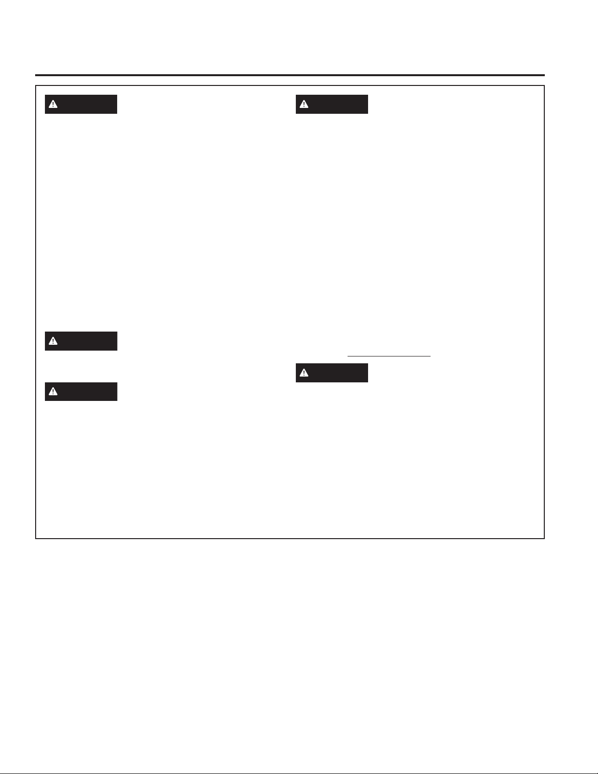
Screen
Front
Camera
Monday
Swipe up on the screen
to access controls.
25 °F | L
USING THE KITCHEN HUB: Hardware / Contol Features
RXLVYLOOH
Speaker
, February 12
Volume Button
On/Off
Cooktop Camera
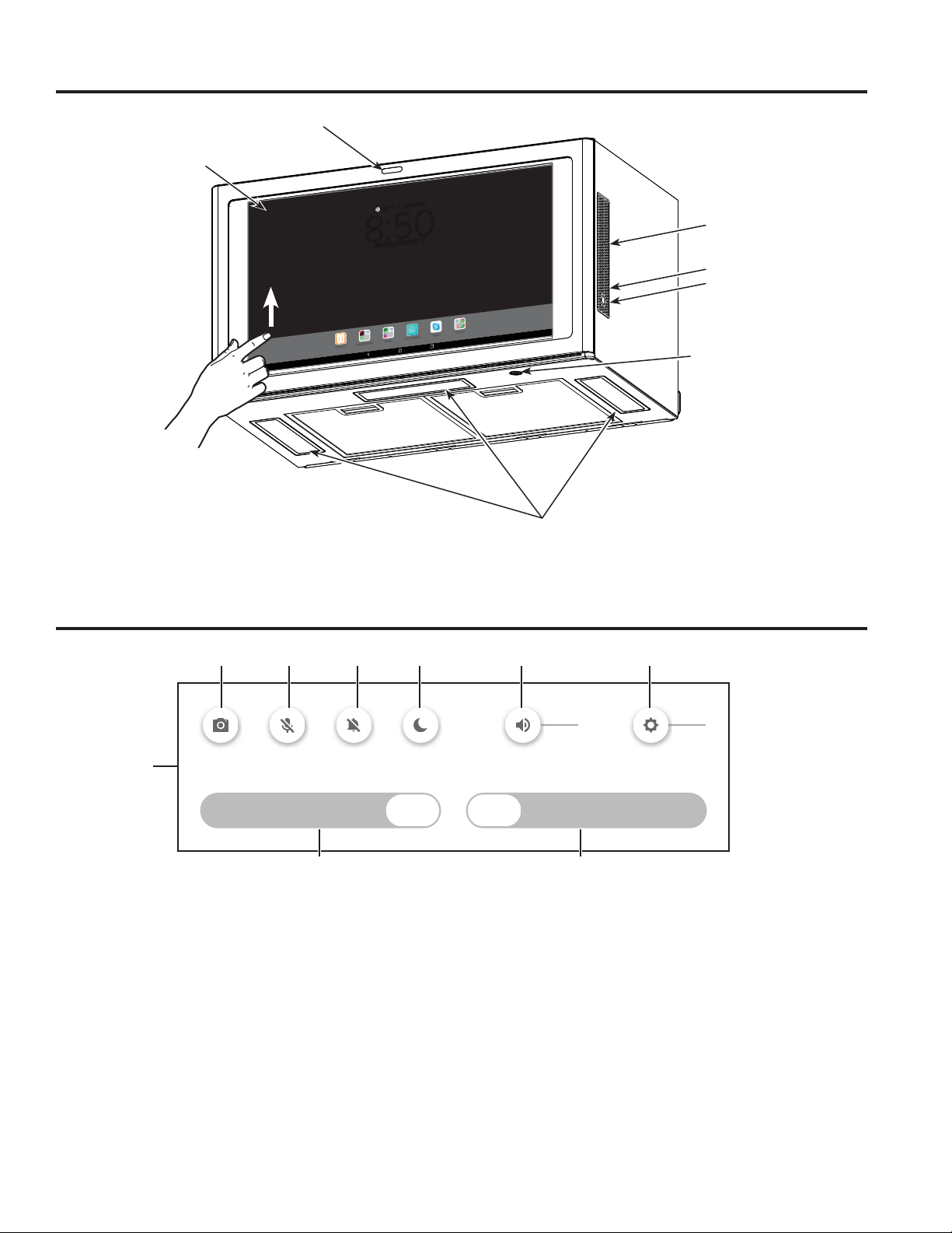
Control Features
34 57 8 9
1
FAN
OFF LOW MED HIGH BOOST
26
1. Ventilation Fan and Light Control Screen
2. FAN: Speed control for fan. Tap LOW for LOW
speed. MED for MEDIUM speed and HIGH for
HIGH speed. Tap BOOST for BOOST speed.
3. Camera: Select to take a picture of your cooking
surface.
4. Microphone: Select to mute/unmute.
5. Notification: Select to turn notification sounds on
and off.
Lights
LIGHT
OFF DIM HIGH
6. LIGHT: Light level control. Tap DIM for low light, MED
for medium light, and HIGH for bright light.
7. Lock: Select to lock screen controls.
8. Volume: Slide to increase or decrease media
volume.
9. Brightness: Slide to increase or decrease screen
brightness.
For Android device setup, and for Android help, please
reference the Setup Wizard on the Kitchen Hub.
49-2000492 Rev. 0 5
Page 6

USING THE KITCHEN HUB
Connecting your WiFi Connect Enabled Appliance
Your GE Appliances Kitchen Hub is recommended to be
connected to WiFi.
Heat Sensor
This unit is equipped with a heat sensor that will
activate the ventilation FAN if excessive temperatures
are detected above the cooktop surface to protect the
Kitchen Hub components from overheating.
Screen Moisture Protection System
Your Kitchen Hub is equipped with a screen protection
system. The system expels small amounts of air around
and below the screen to keep the touchscreen area
dry and clean by preventing condensation or other
substances during cooktop operation.
Use the Setup Wizard to connect unit to WiFi.
If FAN is OFF and excessive temperature is detected,
the FAN will automatically turn to LOW speed. You may
adjust FAN speed to MEDIUM, HIGH, or BOOST, but
you will not be able to turn to OFF until temperatures
return to an acceptable level.
The system is on while the screen is in the awake
state and off when the screen is in screensaver mode
or off position. Operating the cooktop while screen
protection system is off may result in condensation
on the touchscreen. It is recommended to activate
screen during cooking to prevent this from happening. If
condensation build up continues while protection system
is active, turn the ventilation FAN on to provide additional
protection.
USING THE KITCHEN HUB: WiFi / Heat Sensor / Screen Moisture Protection
6 49-2000492 Rev. 0
Page 7
Filters
Be sure the circuit breaker is off and all surfaces are cool before cleaning or servicing any interior part of the unit.
Metal Grease Filter
The metal filters trap grease during cooking.
The filters must ALWAYS be in place when the unit is in
use. The grease filters are dishwasher-safe and should
be cleaned every month, depending on the usage of the
unit.
To remove:
Press on the filter handle to disengage the filter lock to
release the filter.
To replace:
Fit the tabs at the bottom of the filter into the slots in the
back of the filter opening. Lift up the front side of the filter
and push gently until the filter locks into place. Make sure
the filter lock is in the closed position to secure the filter.
To clean:
Swish the filter in hot soapy water and rinse in clean
water or wash it in the dishwasher. Do not use abrasive
cleansers.
NOTE: Some discoloration of the filter may occur in the
dishwasher.
Metal Grease
Filter
USING THE KITCHEN HUB: Filters
Charcoal Filter (for recirculation installation only)
If the model is not vented to the outside, the air needs to
be recirculated through a disposable charcoal filter that
helps remove smoke and odors.
NOTE: DO NOT rinse, or put charcoal filter in an
automatic dishwasher.
The charcoal filters are included with the unit. They
cannot be cleaned. It is recommended that the
charcoal filter be replaced every 6 months or if it is
noticeably dirty or discolored.
Order Charcoal Filter UXCF91
To inquire about purchasing replacement charcoal filters
or to find the location of a dealer nearest you, please call
our toll-free number:
National Parts Center 800.626.2002
To install:
1. Remove the metal filters—see Metal Grease Filter
section.
2. Install the charcoal filter mounts to either side of the
motor.
3. Insert the snap on the charcoal filter into the center on
the mount.
4. Clip the charcoal filter in until it is locked.
5. Repeat with second filter on the other side of the motor.
6. Replace the metal filters - See Metal Grease Filter section.
To remove:
1. Remove the metal filters—see Metal grease filter
section.
2. Remove the charcoal filter on each side of the blower.
Charcoal
Filter Mount
49-2000492 Rev. 0 7
Page 8
Surfaces
Stainless Steel Surfaces (on some models)
Do not use a steel wool pad; it will scratch the
surface.
To clean the stainless steel surface, use warm sudsy
water or a stainless steel cleaner or polish. Always wipe
the surface in the direction of the brush line. Follow
the cleaner instructions for cleaning the stainless steel
surface. Cleaners with oxalic acid such as Bar Keepers
Friend Soft Cleanser™ will
remove surface rust, tarnish, and
small blemishes. To receive a
coupon for a trial sample of Bar
Keepers Friend Soft Cleanser™
follow the link below or scan the
QR Code.
barkeepersfriend.com/ge
Painted Surfaces and Black Stainless Color (on some models)
Do not use a steel wool pads or other abrasive
cleaners; they will scratch the surface.
CARE AND CLEANING: Surfaces
Clean grease-laden surfaces frequently. To clean
the outer surface, use a hot, damp cloth with a mild
detergent suitable for painted surfaces. Use a clean, hot,
damp cloth to remove soap. Dry with a dry, clean cloth.
Use only a liquid cleanser free of grit and rub in the
direction of the brush lines with a damp soft sponge.
To inquire about purchasing stainless steel appliance
cleaner or polish, or to find the location of a dealer
nearest you, please call our toll-free number:
National Parts Center
800.626.2002
GEApplianceParts.com
NOTE: When cleaning, take care not to come in contact
with filters and other surfaces.
How to Clean the Outside
We recommend against using cleaners with
ammonia or alcohol, as they can damage the
appearance of the appliance. If you choose to use
a common household cleaner, first apply the cleaner
directly to a clean cloth, then wipe the soiled area.
Case
Clean the outside of the appliance with a sudsy cloth.
Rinse and then dry. Do not use appliance wax, polish,
bleach or products containing chlorine on Stainless Steel
finishes.
Screen
Wipe with a damp cloth or glass cleaner such as
Windex. Dry thoroughly. Do not use large amounts of
soap and water, sharp objects or abrasives - they can
damage it.
Bottom
Clean off the grease and dust on the bottom often. Use a
solution of warm water and detergent.
Cooktop Camera
Use a dry, soft cloth to clean the cooktop camera.
8 49-2000492 Rev. 0
Page 9
INSTALLATION INSTRUCTIONS
Installation
Kitchen Hub
UVH1301
Instructions
“If you have questions, call GE Appliances at 800.GE.CARES (800.432.2737)
or visit our website at: GEAppliances.com”
BEFORE YOU BEGIN
Read these instructions completely and carefully.
Ŷ
IMPORTANT — Save these
instructions for local inspector’s use.
Ŷ
IMPORTANT — Observe all governing
codes and ordinances.
Ŷ
Note to Installer – Be sure to leave these
instructions with the Consumer.
Ŷ
Note to Consumer – Keep these instructions for
future reference.
Ŷ
Skill level – Installation of this appliance requires
basic mechanical and electrical skills.
Ŷ
Completion time – Approximately 1 to 3 hours
Ŷ
Proper installation is the responsibility of the
installer.
Ŷ
Product failure due to improper installation is not
covered under the Warranty.
WARNING
ELECTRIC SHOCK OR INJURY TO PERSONS,
OBSERVE THE FOLLOWING:
A. Installation work and electrical wiring must be
done by qualified person(s) in accordance with
all applicable codes and standards, including
fire-rated construction.
B. Sufficient air is needed for proper combustion
and exhausting of gases through the flue
(chimney) of fuel burning equipment to prevent
back drafting. Follow the heating equipment
manufacturer’s guidelines and safety standards
such as those published by the National Fire
Protection Association (NFPA), the American
Society for Heating, Refrigeration and Air
Conditioning Engineers (ASHRAE) and the local
code authorities.
C. When cutting or drilling into wall or ceiling, do
not damage electrical wiring and other hidden
utilities.
D. Ducted fans must always be vented to the
outdoors.
TO REDUCE THE RISK OF FIRE,
E. When applicable, install any makeup
(replacement) air system in accordance with local
building code requirements. Visit GEAppliances.
com for available makeup air solutions.
WARNING
USE ONLY METAL DUCT WORK.
TO REDUCE THE RISK OF FIRE,
49-2000492 Rev. 0 9
Page 10
Installation Instructions
IMPORTANT SAFETY INSTRUCTIONS
GROUNDING INSTRUCTIONS
This appliance must be grounded. In the event of an
electrical short circuit, grounding reduces the risk of
electric shock by providing an escape wire for the
electric current. This appliance is equipped with a
cord
having a grounding wire with a grounding plug. The
plug must be plugged into an outlet that is properly
installed and grounded.
WARNING
a risk of electric shock.
Consult a qualified electrician if the grounding
instructions are not completely understood, or if
doubt exists as to whether the appliance is properly
grounded.
Do not use an extension cord. If the power supply
cord is too short, have a qualified electrician install
an outlet near the appliance.
INSTALLATION INSTRUCTIONS
Where a standard two-prong wall receptacle
is encountered, it must be replaced with
a properly grounded three-prong wall
receptacle, installed by a qualified electrician.
WARNING
Can cause injury or death: DO NOT, under any
circumstances, cut, deform or remove any of the
prongs from the power cord. Failure to comply
may cause fire.
Improper grounding can result in
Risk of Electric Shock.
ELECTRICAL REQUIREMENTS
120 V Models
This product requires a three-prong grounded
outlet. Product rating is 120 volts AC, 60 Hertz.
This product must be connected to a supply circuit
of the proper voltage and frequency. Wire size
must conform to the requirements of the National
Electrical Code or the prevailing local code. The
outlet box should be located in the cabinet above
the unit and away from any potential ducting. The
outlet box and supply circuit should be installed by
a qualified electrician and conform to the National
Electrical Code or the prevailing local code.
CAUTION
mounting surface must be capable of supporting
the cabinet load of this 75 pound product.
CAUTION
cannot be installed in cabinet arrangements
such as an island or a peninsula. It must be
mounted to BOTH a top cabinet AND a back
wall.
CAUTION
injury (back injury or other injuries due to
excessive weight of the product) or property
damage, you will need two people to install this
product.
For personal safety, the
For personal safety, this product
To avoid the risk of personal
10 49-2000492 Rev. 0
Page 11

MOUNTING SPACE
Ǝ
max.
òƎ
Ǝ
Ǝ
ƎPLQIURP
the floor to
the bottom of
the cabinet.
69" is the
recommended
distance.
Installation Instructions
Ǝ
min.
Bottom edge of
cabinet needs
WREHƎRU
more from
the cooking
surface or
top surface
of gas grates,
whichever is
Backsplash
NOTES:
7KHVSDFHEHWZHHQWKHFDELQHWVPXVWEHƎZLGH
and free of obstructions.
• If you are going to vent your unit to the outside,
see Installation Types 2A or 2C for cabinet and wall
preparation.
taller
• When installing the unit beneath smooth, flat
cabinets, be careful to follow the instructions on the
top cabinet template for power cord clearance.
• Maximum cabinet depth above and beside the unit
is 13” max for standard installation. 15" cabinet
depth requires additional steps using an additional
installation kit JKX15BUMPWW/BB.
• For models setup in Recirc Exhaust: Do not allow
cabinetry or other objects to block the airflow of the
vent.
• The product should not be installed over any cooktop
or range with a combined cooktop BTU greater than
72,000 BTU.
INSTALLATION INSTRUCTIONS
49-2000492 Rev. 0 11
Page 12

Installation Instructions
TOOLS AND MATERIALS REQUIRED
(NOT SUPPLIED)
PARTS NEEDED FOR INSTALLATION
Ŷ 1 Wall or Roof Cap (for ducted venting only)
Ŷ All Metal Ductwork (for ducted venting only)
Safety glasses
Pencil and tape measure
Phillips screwdriver
DAMAGE – SHIPMENT/INSTALLATION
• If the unit is damaged in shipment, return the
• If the unit is damaged by the customer, repair or
Level
• If the unit is damaged by the installer (if other
Aluminized
Rectangular duct and
adaptors as needed per
installation
(length will vary)
duct tape
PARTS INCLUDED
Gloves
HARDWARE PACKET
INSTALLATION INSTRUCTIONS
Tin snips
Scissors (to cut
template, if necessary)
unit to the store in which it was bought for repair or
replacement.
replacement is the responsibility of the customer.
than the customer), repair or replacement must
be made by arrangement between customer and
installer.
PART QUANTITY
Wood Screws
2
(3/16” x 2”)
Toggle Bolts (and
4
wing nuts) (1/4” x 3”)
Electric drill with #2 Phillips bit
Saw (saber, hole or keyhole)
Drill bits: 2", 3/16", 5/8"
Filler blocks or scrap
wood pieces, if needed
for top cabinet spacing
(used on recessed
bottom cabinet
installations only)
Self-aligning
3
Machine Screw
(1/4”-28 x 3-1/4”)
Nylon Grommet (for
1
metal cabinets)
Power Cord Strap
1
(plastic)
You will find the installation hardware contained in a
packet with the unit. Check to make sure you have
all these parts.
NOTE: Some extra parts are included.
12 49-2000492 Rev. 0
Page 13

Installation Instructions
INSTALLATION INSTRUCTIONS
PARTS INCLUDED
ADDITIONAL PARTS
PART QUANTITY
≤
≤
≤
Top Cabinet
Template
Rear Wall
Template
Owner's
Manual
Exhaust
Adaptor
Charcoal
Filter
ADVANCE PLANNING
Duct Install Planning (for outside exhaust only)
Ŷ8VHPHWDOGXFWZRUNRQO\
1
1
1
1
2
Ŷ'HWHUPLQHWKHH[DFWORFDWLRQRIWKHDSSOLDQFH
Ŷ3ODQWKHURXWHIRUYHQWLQJH[KDXVWWRWKHRXWGRRUV
To maximize the ventilation performance of the
vent system:
1. Minimize the duct run length and number of
transitions and elbows.
2. Maintain a constant duct size.
3. Seal all joints with duct tape to prevent any
leaks.
NOTE: Flexible vent is not recommended. Flexible
vent creates back pressure and air turbulence that
greatly reduces performance.
Ŷ0D[LPXPHTXLYDOHQWGXFWOHQJWKIRU&)0
150 foot.
Ŷ,QVWDOODZDOOFDSRUURRIFDSZLWKGDPSHUDWWKH
exterior opening. Purchase the wall or roof cap
and any transition and length of duct needed in
advance.
Ŷ:KHQDSSOLFDEOHLQVWDOODQ\PDNHXS
(replacement) air system in accordance with local
building code requirements. Use makeup air kit
JXMUA8.
Vent system can terminate either through the roof
or the wall.
Roof Cap
Round Duct
Add Insulation
and/or Caulk
Wall Cap
Add tape to joint
Kitchen Hub
Add Insulation
and/or Caulk
Recirculation Install Planning
Charcoal filters (included) are necessary for
recirculation installation.
49-2000492 Rev. 0 13
Page 14

Installation Instructions
1. PLACEMENT OF THE MOUNTING PLATE
REMOVING THE KITCHEN HUB
A
FROM THE CARTON/REMOVING
THE MOUNTING PLATE
Remove the packaging
CAUTION
sharp edges.
1. Open the box and fold back all four carton
flaps fully against the carton sides. Remove the
following items from the protective foam: charcoal
filters, cord plug, damper, and screws. Do not
remove the foam protecting the front of the unit.
2. Carefully roll the unit and carton over onto the top
side. The unit should be resting in the foam.
3. Pull the carton up to remove.
Wear gloves to protect against
1. Find the studs, using one of the following methods:
INSTALLATION INSTRUCTIONS
Carton
2. After locating the stud(s), find the center by probing
Foam
3. Draw a line down the center of the stud.
IMPORTANT: The unit must be installed to at least
4. The mounting plate is attached to the back of
the unit. Remove the two screws holding it to
the back. The plate will be used as the rear wall
template and for mounting the unit to the wall.
one wall stud.
FINDING THE WALL STUDS
B
Wall
Studs
Center
A. Stud finder
OR
B. Use a hammer to tap lightly across the
mounting surface to find a solid sound. This will
indicate a stud location.
the wall with a small nail to find the edges of the
stud. Then place a mark halfway between the
edges. The center of any adjacent studs should be
ƎRUƎIURPWKLVPDUN
Screws
Mounting Plate
5. Set the unit upright. Remove and properly discard
plastic bags and foam.
14 49-2000492 Rev. 0
Page 15

Installation Instructions
1. PLACEMENT OF THE MOUNTING PLATE (Cont.)
DETERMINING MOUNTING PLATE LOCATION UNDER YOUR CABINET
C
INSTALLATION INSTRUCTIONS
Plate Position – flat bottom cabinet
Mounting Plate
Tabs Touching
the Cabinet
Bottom
At least 30"
Plate Position – recessed cabinet bottom
Mounting Plate
Tabs Touching the
Back Frame of the
Cabinet
ƎWR&RRNWRS
Plate Position – cabinet with front overhang
Mounting Plate
with Tabs Below
Cabinet Bottom the
Same Distance as
the Front Overhang
Depth
ƎWR&RRNWRS
Your cabinets may have decorative trim that
interferes with the unit installation. You may need
to remove the decorative trim to install the unit
properly and to make it level.
THE KITCHEN HUB MUST BE LEVEL.
Use a level to make sure the cabinet bottom is
level.
If the cabinets have a front overhang, install the
mounting plate down the same distance as the front
overhang depth. This will keep the unit level.
1. Measure the inside depth of the front overhang.
2. Draw a horizontal line on the back wall an equal
distance below the cabinet bottom as the inside
depth of the front overhang.
3. For this type of installation with front overhang,
align the mounting tabs with this horizontal line,
not touching the cabinet bottom as described in
Step D.
49-2000492 Rev. 0 15
Page 16

Installation Instructions
1. PLACEMENT OF THE MOUNTING PLATE (Cont.)
ALIGNING THE MOUNTING PLATE
D
30”
Hole B
Hole A
INSTALLATION INSTRUCTIONS
Draw a
Vertical Line
on Wall from
Center of Top
Cabinet
Hole C
Area E
CAUTION
sharp edges.
1. Draw a vertical line on the wall at the center of the
ƎZLGHVSDFH
2. Use the mounting plate as the template for the rear
wall. Place the mounting plate on the wall, making
sure that the tabs are touching the bottom of the
cabinet or the level line drawn in Step C for cabinets
with front overhang. Line up the notch and center line
on the mounting plate to the center line on the wall.
3. While holding the mounting plate with one hand,
draw circles on the wall at holes A, B, C, and D (see
illustration above/actual plate marked with arrows) .
Four holes must be used for mounting.
Wear gloves to protect against
Hole D
Notch
NOTE: Holes C and D are inside area E. If neither
C nor D is in a stud, find a stud somewhere in area
E and draw a fifth circle to line up with the stud. It is
important to use at least one wood screw mounted
firmly in a stud to support the weight of the unit.
Set the mounting plate aside.
WARNING
injury or death. Take care to not drill into electrical
wiring inside walls or cabinets.
4. Drill holes on the circles. If there is a stud, drill a
»ƎKROHIRUZRRGVFUHZV)RUKROHVWKDWGRQ¶WOLQH
XSZLWKDVWXGGULOOD»ƎKROHIRUWRJJOHEROWV
NOTE: DO NOT MOUNT THE PLATE AT THIS TIME.
Risk of electric shock. Can cause
16 49-2000492 Rev. 0
Page 17

Installation Instructions
2. INSTALLATION TYPES (Choose A, B or C)
INSTALLATION INSTRUCTIONS
This appliance is designed for adaptation to the
following 3 types of ventilation:
A. Outside Top Exhaust (Vertical Duct)
B. Recirculating (Non-Vented Ductless)
C. Outside Back Exhaust (Horizontal Duct)
OUTSIDE TOP EXHAUST
A
(VERTICAL DUCT)
See page 18.
NOTE: Select the type of ventilation required for
your installation and proceed to that section. This
unit is shipped assembled for outside top exhaust.
RECIRCULATING
B
(NON-VENTED DUCTLESS)
See page 21.
OUTSIDE BACK EXHAUST
C
(HORIZONTAL DUCT)
See page 25.
49-2000492 Rev. 0 17
Page 18

Installation Instructions
A. OUTSIDE TOP EXHAUST (Vertical Duct)
INSTALLATION OVERVIEW
A1. Attach Mounting Plate to Wall
A2. Prepare Top Cabinet
A3. Adjust Blower Exhaust
A4. Install Exhaust Adaptor
A5. Mount the Kitchen Hub
A6. Connect Ductwork
A7. Finalize Installation
ATTACH THE MOUNTING PLATE
A1
TO THE WALL
A
INSTALLATION INSTRUCTIONS
C
Attach the plate to the wall using toggle bolts. At
least one wood screw must be used to attach the
plate to a wall stud. Recommended locations on the
mounting plate are indicated by A, B, C and D.
1. Remove the toggle wings from the bolts.
2. Insert the bolts into the mounting plate through
the holes designated to go into drywall and
UHDWWDFKWKHWRJJOHZLQJVWR»ƎRQWRHDFKEROW
To use toggle bolts:
Spacing for Toggles More
Than Wall Thickness
Mounting
Plate
Toggle Wings
B
fingers between the back of the mounting plate
and the wall.
4. Tighten all bolts. Pull the plate away from the wall
D
You need to drill holes for the top support screws
and a hole large enough for the power cord to fit
through, and a cutout large enough for the exhaust
adaptor.
Toggle
Bolt
ATTACH THE MOUNTING PLATE
A1
TO THE WALL (Cont.)
CAUTION
to help tighten the bolts.
A2
USE TOP CABINET TEMPLATE
Be careful to avoid pinching
FOR PREPARATION OF TOP
CABINET
Wall
Mounting Plate
3. Place the mounting plate against the wall and
insert the toggle wings into the holes in the wall to
mount the plate.
NOTE: Before tightening toggle bolts and wood
screw, make sure the tabs on the mounting plate
touch the bottom of the cabinet when pushed
flush against the wall and that the plate is properly
centered under the cabinet.
Bolt End
• Read the instructions on the TOP CABINET
TEMPLATE.
• Tape it underneath the top cabinet.
• Drill the holes, following the instructions on the
TOP CABINET TEMPLATE.
CAUTION
drilling holes in the cabinet bottom.
Wear safety goggles when
18 49-2000492 Rev. 0
Page 19

Installation Instructions
A. OUTSIDE TOP EXHAUST (Vertical Duct) (Cont.)
INSTALLATION INSTRUCTIONS
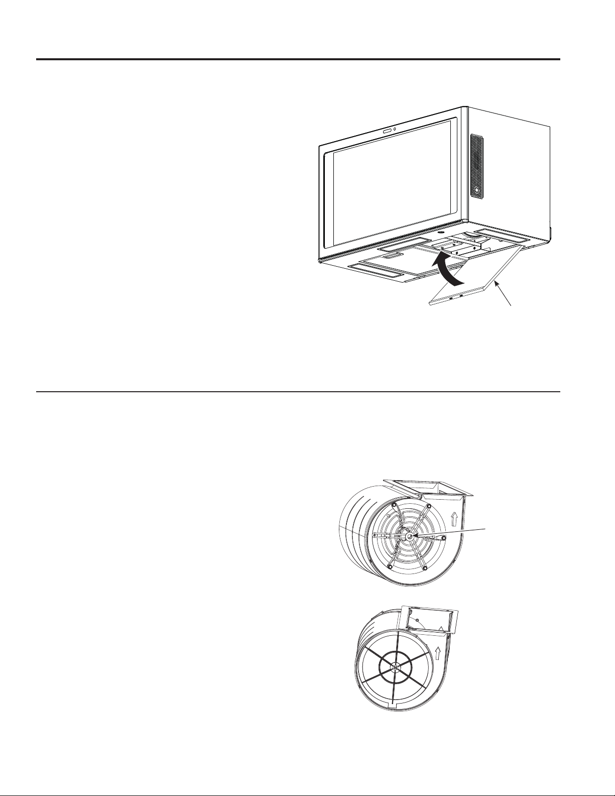
A3
ADJUST BLOWER EXHAUST
The unit is shipped in the top exhaust configuration.
If configuration is not in the top exhaust direction,
follow the steps below.
CAUTION
sharp edges.
1. Remove damper mounting plate and diverter.
2. Remove diverter from angled position and reinsert
vertically as shown.
3. Reattach the damper mounting plate with opening
on top of unit as shown.
Wear gloves to protect against
A4
ASSEMBLE AND INSTALL
ADAPTOR
Screws
Damper
1. Remove 3 screws shown above. Position the
damper on top of the damper mounting plate and
secure with removed screws.
2. Remove the tape from the damper. Make sure
that the damper pivots easily before mounting
the unit.
You will need to make adjustments to assure
proper alignment with your house exhaust duct
after the unit is installed.
49-2000492 Rev. 0 19
Page 20

Installation Instructions
A. OUTSIDE TOP EXHAUST (Vertical Duct) (Cont.)
A5
MOUNT THE KITCHEN HUB
Cabinet Front
CAUTION
injury (back injury or other injuries due to
excessive weight of the unit) or property
damage, you will need two people to install this
product.
IMPORTANT: Do not put any pressure on front
screen during installation.
WARNING
INSTALLATION INSTRUCTIONS
cause injury or death: If installing unit with metal
cabinets, cover the edge of the power supply
cord hole with the nylon grommet in hardware
bag.
IMPORTANT: If filler blocks are not used, case
damage may occur from overtightening screws.
NOTE: When mounting the unit, thread power cord
through hole in bottom of top cabinet. Keep it tight
throughout Steps 1–3. Do not pinch cord or lift unit
by pulling cord.
1. Lift unit, tilt it forward, and hook slots at back
bottom edge onto four lower tabs of mounting
plate.
To avoid the risk of personal
Risk of Electric Shock. Can
A5
MOUNT THE KITCHEN HUB
(Cont.)
3. Insert 2 self-aligning screws(1/4" - 28 x 3-1/4")
through top-center cabinet hole. Turn two full
turns on each screw.
Cabinet Bottom Shelf
Filler Block
This
Equivalent
to Depth
of Cabinet
Recess
Self-Aligning Screw
Unit Top
4. Tighten the 2 screws to the top of the unit. (While
tightening screws, hold the unit in place against
the wall and the top cabinet.)
distance
can NOT
exceed 2”
to ensure
proper
installation
2. Rotate front of unit up against cabinet bottom.
20 49-2000492 Rev. 0
Page 21

Installation Instructions
A. OUTSIDE TOP EXHAUST (Vertical Duct) (Cont.)
A6
CONNECTING DUCT WORK
1. Extend the house duct down to connect to the
exhaust adaptor.
2. Seal exhaust duct joints using duct tape.
INSTALLATION INSTRUCTIONS
A7
FINALIZE INSTALLATION
Plug in the unit.
49-2000492 Rev. 0 21
Page 22

Installation Instructions
B. RECIRCULATING (Non-Vented Ductless)
INSTALLATION OVERVIEW
B1. Attach Mounting Plate to Wall
B2. Prepare Top Cabinet
B3. Adjust Blower Exhaust
B4. Mount the Kitchen Hub
B5. Filters
B6. Finalize Installation
B1
ATTACH THE MOUNTING PLATE
TO THE WALL
fingers between the back of the mounting plate
INSTALLATION INSTRUCTIONS
Attach the plate to the wall using toggle bolts. At
least one wood screw must be used to attach the
plate to a wall stud.
1. Remove the toggle wings from the bolts.
2. Insert the bolts into the mounting plate through
the holes designated to go into drywall and
UHDWWDFKWKHWRJJOHZLQJVWR»ƎRQWRHDFKEROW
To use toggle bolts:
Spacing for Toggles More
Than Wall Thickness
Toggle Wings
Mounting
Plate
3. Place the mounting plate against the wall and
insert the toggle wings into the holes in the wall to
mount the plate.
NOTE: Before tightening toggle bolts and wood
screw, make sure the tabs on the mounting plate
touch the bottom of the cabinet or the horizontal
level line when pushed flush against the wall and
that the plate is properly centered under the cabinet.
Toggle
Bolt
Wall
Bolt End
and the wall.
4. Tighten all bolts. Pull the plate away from the wall
You need to drill holes for the top support screws
and a hole large enough for the power cord to fit
through.
• Read the instructions on the TOP CABINET
• Tape it underneath the top cabinet.
• Drill the holes, following the instructions on the
drilling holes in the cabinet bottom.
B1
ATTACH THE MOUNTING PLATE
TO THE WALL (Cont.)
CAUTION
to help tighten the bolts.
B2
USE TOP CABINET TEMPLATE
Be careful to avoid pinching
FOR PREPARATION OF TOP
CABINET
TEMPLATE.
TOP CABINET TEMPLATE.
CAUTION
Wear safety goggles when
22 49-2000492 Rev. 0
Page 23

Installation Instructions
B. RECIRCULATING (Non-Vented Ductless)
INSTALLATION INSTRUCTIONS
B3
ADJUST BLOWER EXHAUST
The unit is shipped in the top venting mode exhaust
configuration. The vertical deflector plate should be
repositioned to the angled position.
1. Remove damper mounting plate and diverter.
2. Install diverter in angled position and reinstall
damper mounting plate.
B4
MOUNT THE KITCHEN HUB
CAUTION
injury (back injury or other injuries due to
excessive weight of the unit) or property
damage, you will need two people to install this
product.
IMPORTANT: Do not put any pressure on front
screen during installation.
WARNING
cause injury or death: If installing unit with metal
cabinets, cover the edge of the power supply
cord hole with the nylon grommet in hardware
bag.
NOTE: When mounting the appliance, thread power
cord through hole in bottom of top cabinet. Keep it
tight throughout Steps 1–3. Do not pinch cord or lift
unit by pulling cord.
1. Lift appliance, tilt it forward, and hook slots
at back bottom edge onto four lower tabs of
mounting plate.
To avoid the risk of personal
Risk of Electric Shock. Can
2. Rotate front of appliance up against cabinet
bottom.
49-2000492 Rev. 0 23
Page 24

Installation Instructions
B. RECIRCULATING (Non-Vented Ductless) (Cont.)
B4
MOUNT THE KITCHEN HUB
(Cont.)
,QVHUWVHOIDOLJQLQJVFUHZV»Ǝ[
through outer top cabinet holes. Turn two full
turns on each screw.
Cabinet Front
Cabinet Bottom Shelf
Filler Block
This
Equivalent
to Depth
of Cabinet
Recess
Self-Aligning Screw
Unit Top
INSTALLATION INSTRUCTIONS
4. Tighten the two screws to the top of the unit.
(While tightening screws, hold the unit in place
against the wall and the top cabinet.)
distance
can NOT
exceed 2”
to ensure
proper
installation
1. Remove grease filter and install a charcoal filter
B5
FILTERS
on each side of the motor as shown below.
Charcoal
Filter Mount
B6
FINALIZE INSTALLATION
Plug in the unit.
24 49-2000492 Rev. 0
Page 25

Installation Instructions
C. OUTSIDE BACK EXHAUST (Horizontal Duct)
INSTALLATION OVERVIEW
C1. Prepare Rear Wall
C2. Attach Mounting Plate to Wall
C3. Prepare Top Cabinet
C4. Adjust Blower Exhaust
C5. Mount the Kitchen Hub
C6. Finalize Installation
PREPARING THE REAR WALL
C1
FOR OUTSIDE BACK EXHAUST
You need to cut an opening in the rear wall for
outside exhaust.
ATTACH THE MOUNTING PLATE
C2
TO THE WALL (Cont.)
1. Remove the toggle wings from the bolts.
2. Insert the bolts into the mounting plate through the
holes designated to go into drywall and reattach the
WRJJOHZLQJVWR»ƎRQWRHDFKEROW
To use toggle bolts:
Spacing for Toggles More
Than Wall Thickness
Mounting
Plate
Toggle Wings
Toggle
Bolt
INSTALLATION INSTRUCTIONS
• Read the instructions on the REAR WALL
TEMPLATE.
• Tape it to the rear wall, lining up with the holes
previously drilled for holes A and B in the mounting
plate.
• Cut the opening, following the instructions of the
REAR WALL TEMPLATE.
ATTACH THE MOUNTING PLATE
C2
TO THE WALL
Attach the plate to the wall using toggle bolts. At least
one wood screw must be used to attach the plate to
a wall stud.
Wall
3. Place the mounting plate against the wall and insert
the toggle wings into the holes in the wall to mount
the plate.
NOTE: Before tightening toggle bolts and wood
screw, make sure the tabs on the mounting plate
touch the bottom of the cabinet when pushed flush
against the wall and that the plate is properly centered
under the cabinet.
CAUTION
between the back of the mounting plate and the wall.
4. Tighten all bolts. Pull the plate away from the wall
to help tighten the bolts.
Be careful to avoid pinching fingers
Bolt
End
49-2000492 Rev. 0 25
Page 26

Installation Instructions
C. OUTSIDE BACK EXHAUST (Horizontal Duct) (Cont.)
C3
USE TOP CABINET TEMPLATE
FOR PREPARATION OF TOP
CABINET
You need to drill holes for the top support screws
and a hole large enough for the power cord to fit
through.
C4
ADJUST BLOWER EXHAUST
The unit is shipped in the top exhaust configuration.
To adjust the unit to back exhaust remove damper
mounting plate and reposition such that opening is
in the back of the unit.
CAUTION
sharp edges.
1. Remove 3 screws as shown and save.
2. Remove damper mounting plate by removing
screws.
Wear gloves to protect against
INSTALLATION INSTRUCTIONS
• Read the instructions on the TOP CABINET
TEMPLATE.
• Tape it underneath the top cabinet.
• Drill the holes, following the instructions on the TOP
CABINET TEMPLATE.
CAUTION
drilling holes in the cabinet bottom.
Wear safety goggles when
3. Reposition damper mounting plate such that
opening is in the back of the unit.
4. Reattach screws.
ASSEMBLE AND INSTALL
C5
ADAPTER
1. Remove the tape from the damper. Make sure
that the damper pivots easily before mounting
the unit.
You will need to make adjustments to assure
proper alignment with your house exhaust duct
after the unit is installed.
2. Position the unit damper to back of the unit and
secure it with the screws that were removed.
NOTE: Damper must hinge at the top as shown
below.
26 49-2000492 Rev. 0
Page 27

Installation Instructions
C. OUTSIDE BACK EXHAUST (Horizontal Duct) (Cont.)
INSTALLATION INSTRUCTIONS
C6
MOUNT THE KITCHEN HUB
CAUTION
risk of personal injury (back
injury or other injuries due to
excessive weight of the unit)
or property damage, you will
need two people to install
this product.
IMPORTANT: Do not put any pressure on front
screen during installation.
WARNING
cause injury or death: If installing unit with metal
cabinets, cover the edge of the power supply
cord hole with the nylon grommet in hardware
bag.
IMPORTANT: If filler blocks are not used, case
damage may occur from overtightening screws.
NOTE: When mounting the unit, thread power cord
through hole in bottom of top cabinet. Keep it tight
throughout Steps 1–3. Do not pinch cord or lift unit
by pulling cord.
1. Lift unit, tilt it forward, and hook slots at back bottom
edge onto four lower tabs of mounting plate.
To avoid the
Risk of Electric Shock. Can
C6
MOUNT THE KITCHEN HUB
(Cont.)
2. Rotate front of unit up against cabinet bottom.
3. Insert 2 self-aligning screws (1/4”-28 x 3-1/4”)
through top-center cabinet hole. Turn two full
turns on each screw.
Cabinet Front
Cabinet Bottom Shelf
Filler Block
Equivalent
to Depth
of Cabinet
Recess
Self-Aligning Screw
Unit Top
4. Tighten the 2 screws to the top of the unit. (While
tightening screws, hold the unit in place against
the wall and the top cabinet.)
This
distance
can NOT
exceed 2”
to ensure
proper
installation
C7
FINALIZE INSTALLATION
Plug in the unit.
49-2000492 Rev. 0 27
Page 28

Installation Instructions
MAKE UP AIR TECHNOLOGY
Note to Installers and Inspectors: This product comes equipped with a simple installation feature that limits
maximum CFM levels in order to comply with certain local codes or regulations. This installation method may not
be necessary for all installations, please refer to your local codes for further guidelines.
CAUTION
instructions listed below. Failure to do so could result in personal injury or damage to the product.
To modify unit (if needed for local codes):
390CFM or 290CFM
By design, the maximum blower speed is greater than
400 CFM. For local codes requiring reduced CFM,
modify the wiring as described below:
1. Remove the filters.
2. Remove the control board box cover.
3. Locate the motor harness plugged into the control
TROUBLESHOOTING TIPS
board.
4. A -
For a maximum of 390 CFM
Unit can operate with 4 speeds
(Low, Medium, High, Boost).
1. Disconnect the connector of the blue wire
from the red wire.
2. Connect the 2 red wires together.
B -
For a maximum of 290 CFM
Unit can operate with 3 speeds
(Low, Medium, High).
Disconnect the connector of the blue wire from
the red wire.
NOTE: Boost speed will be disabled. Unit will
operate Low, Med & High only.
5. Reattach the control board box cover and install
Filters, see Filters section.
Note to Inspectors: To verify this product was
installed in either configuration, check motor wiring
connections as described above.
Appliance must be disconnected from main power prior to performing the conversion
Motor Harness
Connector
Control Box Cover
Control Box
Motor Pin
Red
Blue
Red
Motor Harness
28 49-2000492 Rev. 0
Page 29

Troubleshooting tips ... Before you call for service
Save time and money! Review the charts on the following pages first and you may not need to call for service.
Problem Possible Cause What To Do
Fan/Light does not
operate when button is
turned ON
Loud or abnormal
airflow noise
Fan fails to circulate
air or moves air slower
than normal and/or
fan is making loud or
abnormal airflow noise
Fan keeps going off
and on
A house fuse may be blown or a circuit
breaker tripped.
Wrong duct size used in installation. This unit requires 8” ducting to perform optimally.
Obstructions in duct work. Make sure nothing is blocking the vent. Make sure
Damper blade on wall or roof cap may
not be open.
Metal grease filter and charcoal filter (if
present) may be dirty.
Insufficient makeup (replacement) air Sufficient makeup (replacement) air is required for
The motor is probably overheating and
turning itself off. This can be harmful to
the motor.
Replace fuse or reset circuit breaker.
Using smaller duct pipe will cause reduced venting.
Minimize the duct run length and number of transitions
and elbows. GE Appliances service technicians cannot
correct this issue if installed improperly.
your wall or roof cap has a blade or door.
Make sure damper swings freely. Damper blades may
flip over and will not fully open when this happens.
Adjust to original position.
Clean the metal grease filter and replace charcoal filter
(if present). See Care and Cleaning.
exhausting appliances to operate to rating. Check with
local building codes, which may require or strongly
advise the use of makeup air. Visit GEAppliances.com
for available makeup air solutions.
Check to be sure the filters are clean. If off and on
cycling continues, call for service.
TROUBLESHOOTING TIPS
49-2000492 Rev. 0 29
Page 30

GE Appliances Limited Warranty
GEAppliances.com
All warranty service is provided by our Factory Service Centers, or an authorized Customer Care® technician. To
schedule service online, visit us at geappliances.com/service_and_support/, or call GE Appliances at 800.GE.CARES
(800.432.2737). Please have your serial number and your model number available when calling for service.
Servicing your appliance may require the use of the onboard data port for diagnostics. This gives a GE Appliances factory
service technician the ability to quickly diagnose any issues with your appliance and helps GE Appliances improve its
products by providing GE Appliances with information on your appliance. If you do not want your appliance data to be
sent to GE Appliances, please advise your technician not to submit the data to GE Appliances at the time of service.
For the period of GE Appliances will replace
One year
From the date
of the original
purchase
LIMITED WARRANTY
What GE Appliances will not cover:
Ŷ Service trips to your home to teach you how to use
the product.
Ŷ Improper installation, delivery, or maintenance.
Ŷ Failure of the product if it is abused, misused,
modified, or used for other than the intended purpose
or used commercially.
Ŷ Replacement of house fuses or resetting of circuit
breakers.
Ŷ Damage to the product caused by accident, fire,
floods, or acts of God.
Any part of the cooking product which fails due to a defect in materials or workmanship.
During this limited one-year warranty, GE Appliances will provide, free of charge, all labor
and related service costs to replace the defective part.
Ŷ Damage to finish, such as surface rust, tarnish, or small
blemishes not reported within 48 hours of delivery.
Ŷ Incidental or consequential damage caused by
possible defects with this appliance.
Ŷ Damage caused after delivery.
Ŷ Product not accessible to provide required service.
Ŷ Service to repair or replace light bulbs, except for LED
lamps.
EXCLUSION OF IMPLIED WARRANTIES
Your sole and exclusive remedy is product repair as provided in this Limited Warranty. Any implied warranties,
including the implied warranties of merchantability or fitness for a particular purpose, are limited to one year or
the shortest period allowed by law.
This limited warranty is extended to the original purchaser and any succeeding owner for products purchased for home
use within the USA. If the product is located in an area where service by a GE Appliances Authorized Servicer is not
available, you may be responsible for a trip charge or you may be required to bring the product to an Authorized GE
Appliances Service location for service. In Alaska, the limited warranty excludes the cost of shipping or service calls to
your home.
Some states do not allow the exclusion or limitation of incidental or consequential damages. This limited warranty
gives you specific legal rights, and you may also have other rights which vary from state to state. To know what your
legal rights are, consult your local or state consumer affairs office or your state’s Attorney General.
Warrantor: GE Appliances, a Haier company
Louisville, KY 40225
Extended Warranties: Purchase a GE Appliances extended warranty and learn about special discounts that are
available while your warranty is still in effect. You can purchase it online anytime at
geappliances.com/service_and_support/shop-for-extended-service-plans.htm
or call 800.626.2224 during normal business hours. GE Appliances Service will still be there after your warranty expires.
Staple your receipt here. Proof of the original purchase
date is needed to obtain service under the warranty.
30 49-2000492 Rev. 0
Page 31

Accessories
Looking For Something More?
GE Appliances offers a variety of accessories to
improve your cooking and maintenance experiences!
Refer to the Consumer Support page for phone numbers
and website information.
The following products and more are available:
Parts
Make-up Air Kit
Charcoal Filter
Bump Out Kit
Filler Kit
Cleaning Supplies
CitruShine™ Stainless Steel Wipes
CERAMA BRYTE
Bar Keepers Friend Soft Cleanser™
®
Stainless Steel Appliance Cleaner
ACCESSORIES
49-2000492 Rev. 0 31
Page 32

Consumer Support
GE Appliances Website
Have a question or need assistance with your appliance? Try the GE Appliances Website 24 hours a day, any day
of the year! You can also shop for more great GE Appliances products and take advantage of all our on-line support
services designed for your convenience. In the US: GEAppliances.com
Register Your Appliance
Register your new appliance on-line at your convenience! Timely product registration will allow for enhanced
communication and prompt service under the terms of your warranty, should the need arise. You may also mail in the
pre-printed registration card included in the packing material. In the US: GEAppliances.com/register
Schedule Service
Expert GE Appliances repair service is only one step away from your door. Get on-line and schedule your service at
your convenience any day of the year. In the US: GEAppliances.com/service
CONSUMER SUPPORT
or call 800.432.2737 during normal business hours.
Extended Warranties
Purchase a GE Appliances extended warranty and learn about special discounts that are available while your
warranty is still in effect. You can purchase it on-line anytime. GE Appliances Services will still be there after your
warranty expires. In the US: GEAppliances.com/extended-warranty
or call 800.626.2224 during normal business hours.
Remote Connectivity
For assistance with wireless network connectivity (for models with remote enable),
visit our website at GEAppliances.com/connect or call 800.220.6899 in the US.
Parts and Accessories
Individuals qualified to service their own appliances can have parts or accessories sent directly to their homes
(VISA, MasterCard and Discover cards are accepted). Order on-line today 24 hours every day.
In the US: GEApplianceparts.com or by phone at 877.959.8688 during normal business hours.
Instructions contained in this manual cover procedures to be performed by any user. Other servicing
generally should be referred to qualified service personnel. Caution must be exercised, since improper
servicing may cause unsafe operation.
Contact Us
If you are not satisfied with the service you receive from GE Appliances, contact us on our Website with all the
details including your phone number, or write to:
In the US: General Manager, Customer Relations | GE Appliances, Appliance Park | Louisville, KY 40225
GEAppliances.com/contact
Printed in China
32 49-2000492 Rev. 0
 Loading...