

GE UR Switch Module Ethernet Communications Switch, Multilin UR-2S, Multilin UR-2T Quick Start Manual
Page 1
ISO9001:2000
GE Consumer & Industrial
Multilin
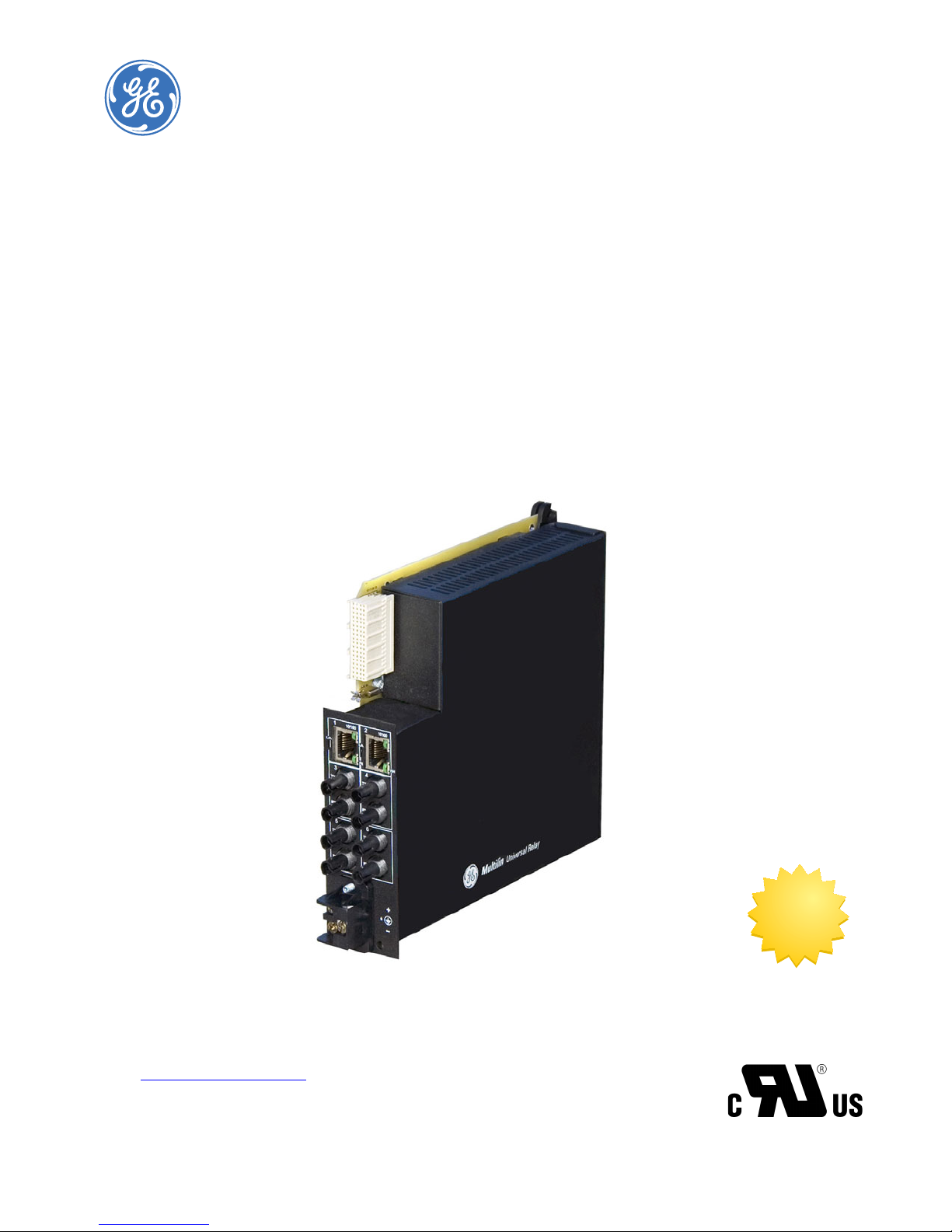
UR Switch Module
Ethernet Communications
Switch
Quickstart Guide
Firmware Revision 3.x
Manual P/N: 1601-9042-A1
Manual Order Code: GEK- 113423
Copyright © 2008 GE Multilin
GE Multilin
215 Anderson Avenue, Markham, Ontario
Canada L6E 1B3
Tel: (905) 294-6222 Fax: (905) 201-2098
Internet: http://www.GEmultilin.com
*1601-0220-A1*
T
E
S
I
R
E
G
D
E
R
I
G
E
GE Multilin's Quality
Management System is
registered to ISO9001:2000
QMI # 005094
UL # E83849
N
I
M
L
I
U
T
L
Page 2

These instructions do not purport to cover all details or variations in equipment nor provide
for every possible contingency to be met in connection with installation, operation, or
maintenance. Should further information be desired or should particular problems arise
which are not covered sufficiently for the purchaser’s purpose, the matter should be referred
to the General Electric Company.
To the extent required the products described herein meet applicable ANSI, IEEE, IEC, and UL
standards; but no such assurance is given with respect to local codes and ordinances
because they vary greatly.
© 2008 GE Multilin Incorporated. All rights reserved.
GE Multilin UR Switch Module Quickstart Guide for revision 3.x.
UR Switch Module is a registered trademark of GE Multilin Inc.
The contents of this manual are the property of GE Multilin Inc. This documentation is
furnished on license and may not be reproduced in whole or in part without the permission
of GE Multilin. The content of this manual is for informational use only and is subject to
change without notice.
Part numbers contained in this manual are subject to change without notice, and should
therefore be verified by GE Multilin before ordering.
Part number: 1601-9042-A1 (June 2008)
Page 3

TABLE OF CONTENTS
Table of Contents
INTRODUCTION TO TWISTED PAIR AND FIBER OPTIC ETHERNET LANS ............QS-1
THERNET PHYSICAL LAYER: TWISTED PAIR COPPER VS FIBER OPTIC ........................ QS-1
E
Twisted Pair copper cable ............................................................................. QS-2
Fiber ......................................................................................................................... QS-2
SUPPORTED NETWORK TOPOLOGIES ................................................................................ QS-3
Star Architecture ................................................................................................ QS-3
Mesh Architecture ............................................................................................. QS-3
Ring Architecture ............................................................................................... QS-3
10BASET AND 100BASET MEDIA ...................................................................................QS-4
Unshielded Twisted Pair cable: ................................................................... QS-4
Ethernet: Unshielded Twisted Pair ............................................................. QS-4
HUBS AND SWITCHES ......................................................................................................QS-7
IBER OPTIC ETHERNET: .....................................................................................................QS-7
F
Wavelengths of light ........................................................................................ QS-7
SINGLE AND MULTI-MODE CABLE ..................................................................................... QS-8
Fiber Cable Cross Section and Physical Specifications ................... QS-8
Difference between Single-mode and Multi-mode Cable .............. QS-9
OPTICAL POWER BUDGET ..................................................................................................QS-9
AXIMUM FIBER SEGMENT LENGTH CALCULATION: ........................................................ QS-11
M
AND UR-2T 10/100 BASET SWITCH PORTS .................................................. QS-12
UR-2S
INTRODUCTION TO THE 2S AND 2T UR MANAGED SWITCH MODULES: ............QS-13
ARDWARE OVERVIEW ....................................................................................................... QS-15
H
AND 2T LED INDICATORS ............................................................................................QS-15
2S
ARDWARE INSTALLATION ................................................................................................. QS-16
H
INITIAL CONFIGURATION PROCEDURE ............................................................................. QS-17
ONFIGURING THE SWITCH IP ADDRESS AND SUBNET MASK USING
C
NERVISTA UR SETUP SOFTWARE. ................................................................ QS-17
E
SSIGNING AN IP ADDRESS TO THE UR SWITCH MODULE
A
USING THE CONSOLE PORT ............................................................................. QS-19
SSIGNING A STATIC IP ADDRESS TO A PERSONNEL COMPUTER ..................................QS-26
A
ELF-TEST ERRORS AND MEANING ...................................................................................QS-31
S
TAGGED VLAN’S .................................................................................................................QS-33
Background .......................................................................................................... QS-33
CONFIGURING TAGGED VLANS ........................................................................................ QS-34
Configuring a VLAN within the Switch ..................................................... QS-34
CONFIGURING THE UR SWITCH FOR RING ONLY MODE .............................................. QS-40
AVING AND LOADING SWITCH SETTINGS ...................................................................... QS-49
S
Saving Switch Settings .................................................................................... QS-49
Loading Switch Settings ................................................................................. QS-49
UR SWITCH MODULE FIRMWARE UPDATES ...............................................................QS-51
PDATING UR SWITCH MODULE FIRMWARE ................................................................. QS-51
U
ELECTING THE PROPER VERSION .................................................................................... QS-51
S
UR SWITCH MODULE – QUICKSTART GUIDE TOC–1
Page 4

TABLE OF CONTENTS
TOC–2 UR SWITCH MODULE – QUICKSTART GUIDE
Page 5
GE Consumer & Industrial
Multilin
UR Switch Module
Ethernet Communications Switch
QuickStart Guide
QuickStart Guide
QS.1 Introduction to Twisted Pair and Fiber Optic Ethernet
LANs
This section will provide a brief review of modern Ethernet media, before covering the steps
used to configure the Multilink switch for typical protective relaying applications. For this
discussion the IP addresses that will be used, are in the range of 3.94.247.1 to 3.94.247.254
using a subnet mask of 255.255.252.0. This same range of addresses can be used for
testing purposes but you should contact your IT support group for a valid range of
addresses to be used for your particular application.
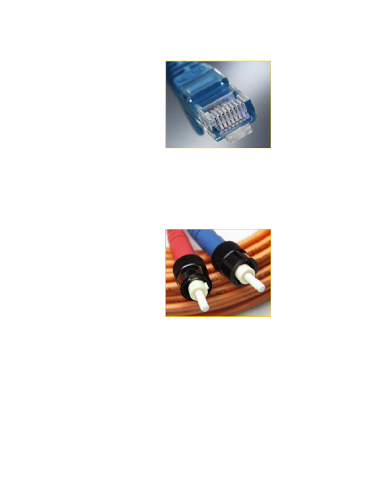
QS.1.1 Ethernet Physical Layer: Twisted Pair Copper vs Fiber Optic
Today, the two most popular physical layer standards for Ethernet are twisted pair copper
cable and fiber optic cable. Twisted pair copper cable is easier to terminate, and has a
lower installation cost, but is susceptible to electrical noise. In addition, a single run of
twisted pair cable is distance-limited.
Fiber optic media can typically be applied over much longer distances, is immune to
electrical noise, and, while being more difficult to terminate, the availability of prefabricated cables has dramatically reduced the complexity of installation within the
substation.
UR SWITCH MODULE – QUICKSTART GUIDE QS–1
Page 6
QUICKSTART GUIDE
Twisted Pair copper cable
• Easy to Terminate
• Low installation costs
• Susceptible to noise interference
• Limited to 100m
• Either shielded or unshielded (UTP)
Fiber
• Longer distances possible, limited only by attenuation
• Immune to electrical noise
• More difficult termination and splicing
• Slightly higher cost for cable
• Two categories:
• multi-mode
• single-mode
QS–2 UR SWITCH MODULE – QUICKSTART GUIDE
Page 7
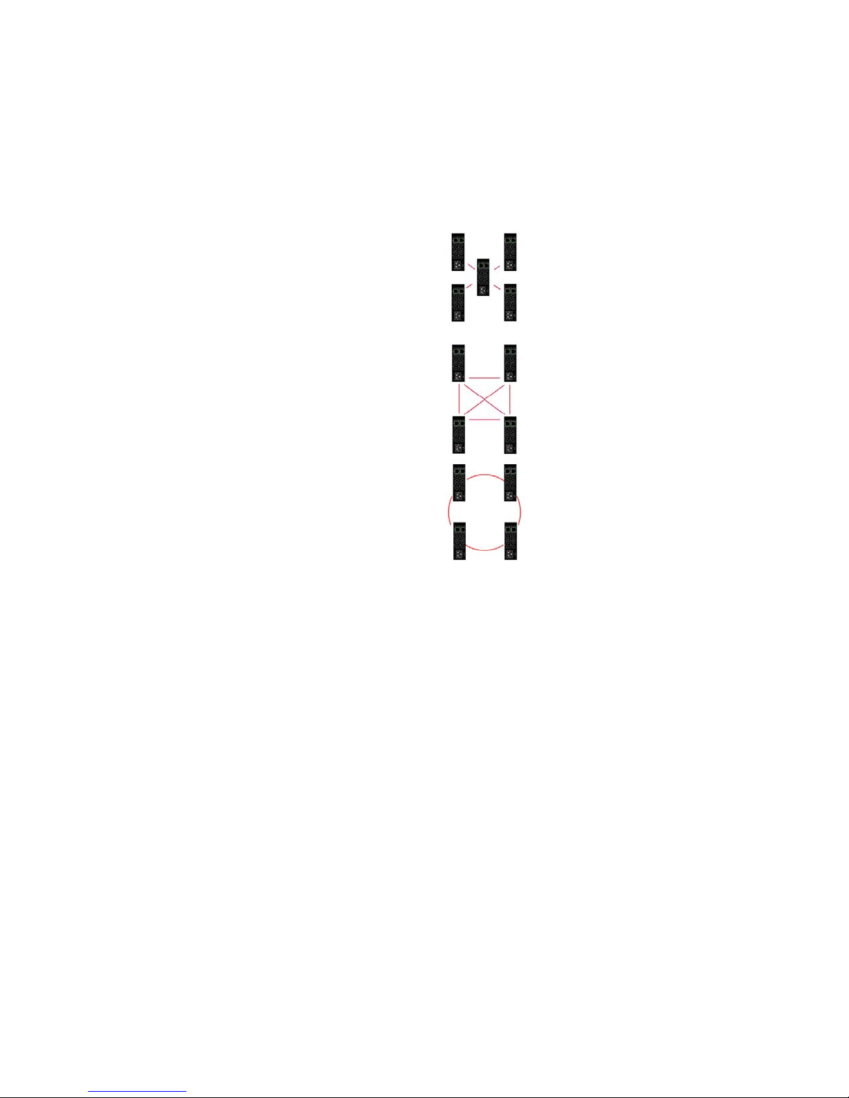
QS.1.2 Supported Network Topologies
With both media, supported topologies include Star, Mesh, and Ring. The port that
connects one switch to another is often called the uplink port and with many switches the
uplink port can operate at much higher baud rates than the standard ports. The link
formed by the connection of several switches’ higher speed uplink ports is often referred to
as a backbone.
QUICKSTART GUIDE
Star
Mesh
Ring
Star Architecture
• Single point of failure before loss of communications
• Additional Ethernet Switches Required
Mesh Architecture
• Multiple points of failure required before loss of communications
• Additional Fiber Cables required
Ring Architecture
• Full Network Redundancy
• Allows for Fastest Network Recovery
• Most Cost Effective Solution
*
UR SWITCH MODULE – QUICKSTART GUIDE QS–3
* RO mode has typical recovery time of ≤ 5 ms/hop.
Page 8
QUICKSTART GUIDE
QS.2 10BaseT and 100BaseT Media
10BaseT and 100BaseT are the two most common twisted pair copper media standards.
There are also several popular fiber optic media standards which we will review later in this
section. With respect to 10 or 100BaseT, the 10 or 100 designation indicates a baud rate of
either 10 or 100 megabits per second (Mbs). Base stands for baseband while the T stands
for twisted pair.
Since many twisted pair interfaces can work at either baud rate the designation 10/
100BaseT has evolved to indicate this capability. Cable can be either unshielded twisted
pair (UTP) or shielded twisted pair (STP).
We recommend category 5e (see below) for applications up to 1000 Mbs.
Unshielded Twisted Pair cable:
• Category 1: Used for telephone communications; not suitable for transmitting
data.
• Category 2: Capable of transmitting data at speeds of up to 4 Mbps.
• Category 3: Can be used in 10BaseT networks; can transmit data at speeds up to
10 Mbps.
• Category 4: Used in Token Ring networks; can transmit data at speeds up to 16
Mbps.
• Category 5: Capable of transmitting data at speeds up to 100 Mbps.
• Category 5e*: Used in networks running at speeds up to 1000 Mbps (1 Gbps).
• Category 6: Consists of four pairs of 24-gauge copper wires, which can transmit
data at speeds of up to 1000 Mbps.
* Recommended
Ethernet: Unshielded Twisted Pair
100 metres max.
:
QS–4 UR SWITCH MODULE – QUICKSTART GUIDE
Page 9
QUICKSTART GUIDE
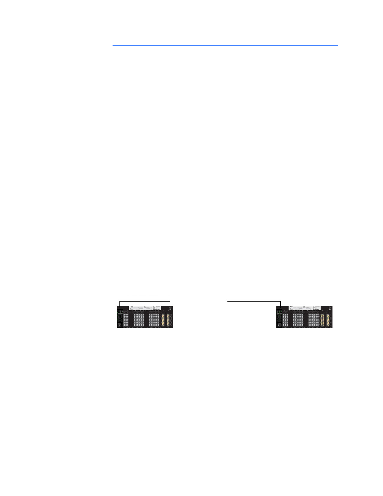
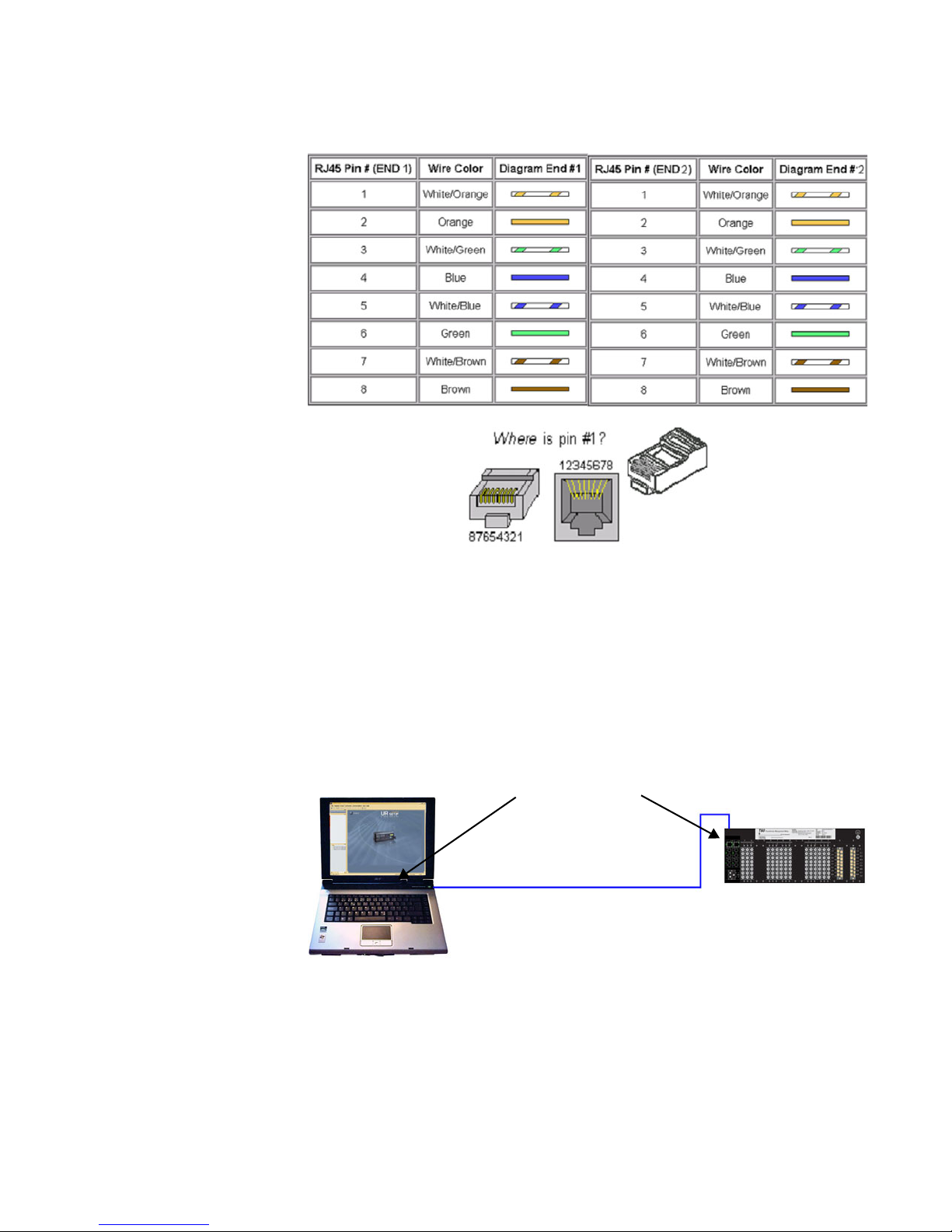
FIGURE QS–1: Pin Layout for a RJ45 Ethernet Straight-through Cable
The cable itself consists of four pairs of wires terminated in RJ45 connectors. The
maximum permitted cable length is 100 meters. The cable pin connections can be one of
two configurations: the first is called a "straight-through" cable and the second is called
either a "crossover" or "patch" cable.
Given that the UR-2S/2T supports autonegotiate, a straight-through or crossover cable
may be used to connect or establish a point-to-point Ethernet LAN between two Ethernet
devices, as shown here.
RJ45 Connectors
100 metres max length
UR SWITCH MODULE – QUICKSTART GUIDE QS–5
Page 10

QUICKSTART GUIDE
FIGURE QS–2: Pin Layout for RJ45 Ethernet Crossover (Patch) Cable
The pin and wire configuration of a patch or crossover cable used to connect or establish a
point-to-point Ethernet LAN between two Ethernet devices, is shown above.
QS–6 UR SWITCH MODULE – QUICKSTART GUIDE
Page 11
QS.3 Hubs and Switches
Two of the major Ethernet network components are hubs and switches. A switch has
many advantages over a hub. Hubs simply transfer information from one port to all other
ports. Since a hub has no way of handling media contention, collisions can occur,
necessitating all segments connected to a hub to work in a half-duplex mode.
Switches on the other hand, are capable of buffering messages, thus allowing full duplex
operation. A switch will also learn the MAC addresses of devices connected to each of it’s
ports and will then route messages to only that port to which the destination device is
connected, thereby reducing data traffic on the network. Switches that use configuration
software to customize both switch and traffic are called “managed switches.” Other
switches - ones that have fixed configurations - are referred to as “unmanaged switches.”
QS.3.1 Fiber Optic Ethernet:
Fiber optic Ethernet is rapidly becoming the medium of choice in applications, such as
power system applications, where longer distances and immunity to EMI are of
importance. Having stated this, the higher cost and the difficulty of terminating fiber
cables allows twisted pair to continue to play a role were appropriate.
QUICKSTART GUIDE
The wavelengths of light used in fiber optic communication are 820, 1300 and 1550
nanometers (nm) because it has been found that these wavelengths are attenuated least
as they travel through the fiber optic medium. Compatible ports must operate at the same
light wavelength, and must be linked with appropriate fiber. There are two categories of
fiber optic cable: multi-mode and single-mode. Note that until recently, cable used with
820nm wavelength light was offered only in multi-mode, while cable used with 1300nm
wavelength light was offered with both single- and multi-mode compatibility. Cable
compatible with 1550nm wavelength light is offered only in single-mode.
Wavelengths of light
Multi-Mode Single-Mode
820nm X X
1300nm X X
1550nm N/A X
Note that both devices must use the same wavelength of light.
UR SWITCH MODULE – QUICKSTART GUIDE QS–7
Page 12
QUICKSTART GUIDE
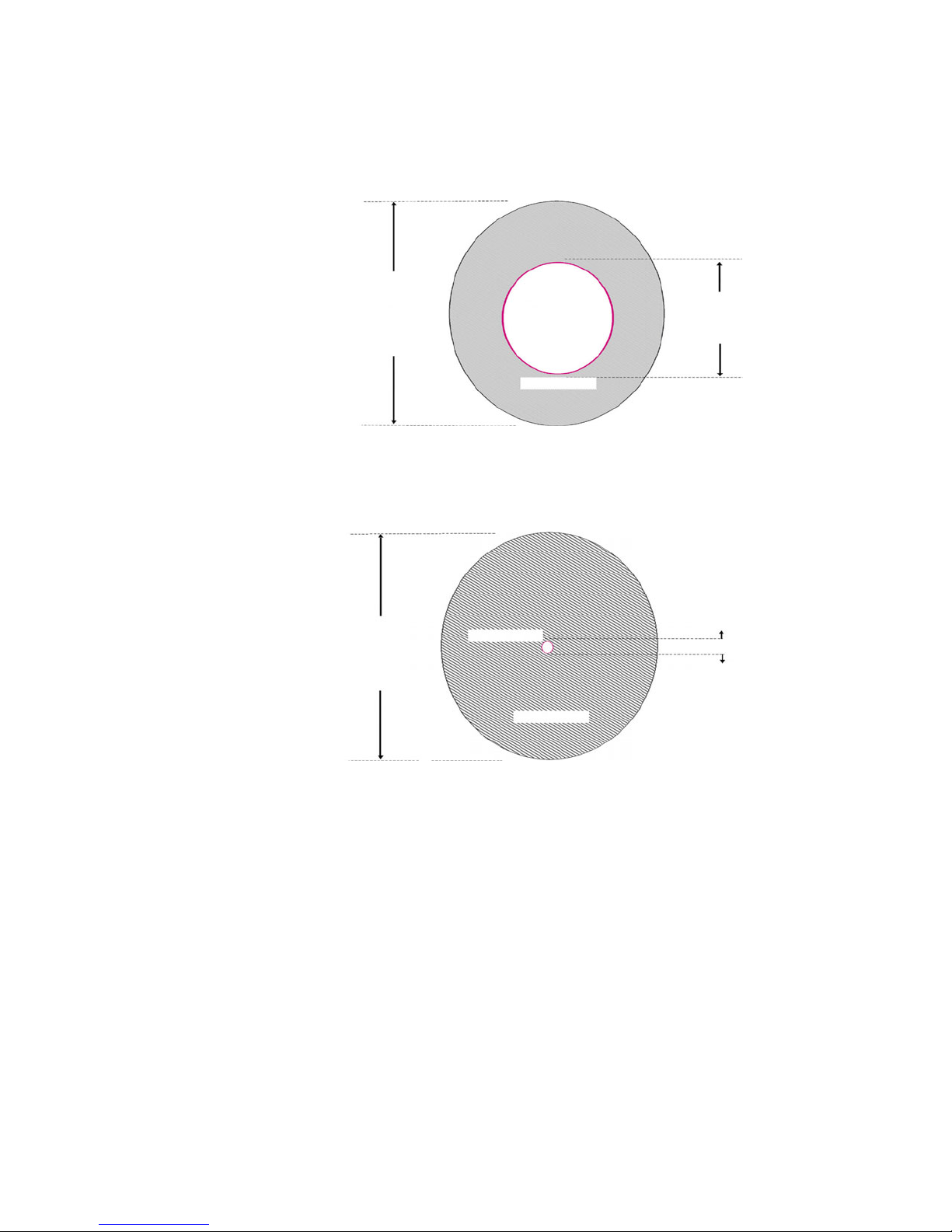
QS.3.2 Single and Multi-mode cable
Fiber Cable Cross Section and Physical Specifications
Multi Mode
• 62.5/125 µm
• 50/125 µm*
Single Mode
125µm
125 µm
CORE
CORE
CLAD
CLAD
62.5µm
8 µm
• 9/125 µm
* Will become more popular as baud rate goes up
The above are scaled drawings of both a 62.5/125 µm multi mode fiber and 9/125µm
single-mode fiber. The outer cladding of both is 125 micrometers in diameter. The multimode core, at 62.5 micrometers, is a little thinner than the average human hair. The core of
QS–8 UR SWITCH MODULE – QUICKSTART GUIDE
Page 13
QUICKSTART GUIDE
the 9/125 micrometer fiber is 8 microns in diameter (almost an eighth of that of the multiMode fiber) surrounded by a second outer layer of cladding. This cladding can pass a light
signal, so for this reason the fiber is referred to as 9 by 125 micrometer fiber.
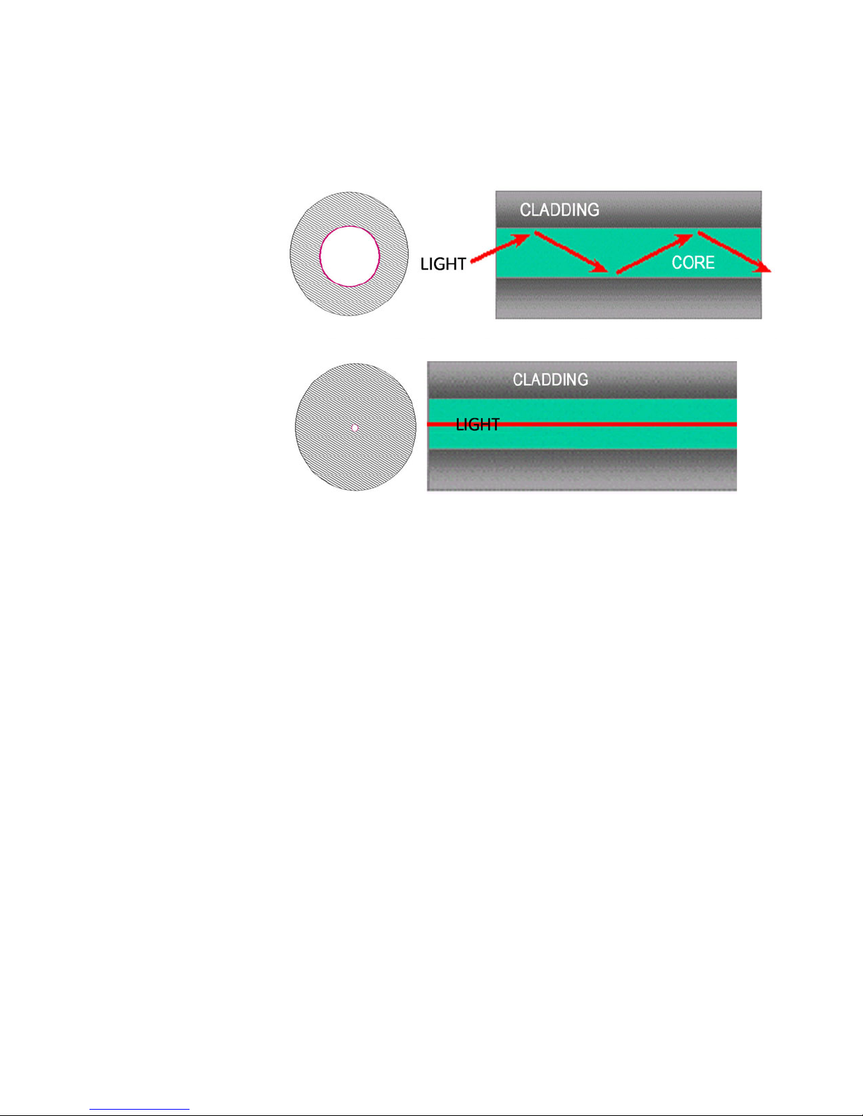
Difference between Single-mode and Multi-mode Cable
The difference between multi-mode and single mode cable can be best described as
follows:
With multi-mode fiber the index of refraction at the surface between the core and the
cladding is such that there is total internal reflection of the light being transmitted down
the core. Picture this by imagining that the clad is a tube whose interior surface is polished
so smooth, it is like a mirror. Light shinning at one end of the tube will either travel straight
down the tube or will travel down the tube by reflecting of the inner mirrored surface.
Single mode fiber can be described as an elongated lens that is continuously focusing the
light into the centre of the fiber. Using these two analogies it can be imagined that in the
single mode fiber more light travels through far less fiber medium resulting in far less
attenuation per unit distance than in multi-mode fiber. As a result, for a given wavelength
of light, single mode fiber typically has less attenuation per unit distance than multi-mode
fiber.
QS.3.3 Optical Power Budget
Inevitably the question that arises is, “What is the maximum practical communication
distance when using a fiber optic cable?”. The answer isn’t straightforward; it must be
calculated in the following way:
FIGURE QS–3: Differences between Multi-Mode and Single-Mode Cable
First the Optical Power Budget is determined by subtracting the receiver’s rated sensitivity
from the transmitter’s rated power, both of which are rated in decibels of light intensity. For
example, if a particular transmitter is rated at -15 db and the receiver’s sensitivity is rated
UR SWITCH MODULE – QUICKSTART GUIDE QS–9
Page 14

QUICKSTART GUIDE
at -31 db the difference of 16 db is the Optical Power Budget. The Optical Power Budget
can be thought of as the maximum permitted attenuation of the light signal as it travels
from the transmitter to the receiver, while still permitting reliable communication.
The next step is to calculate the worst case optical power budget by subtracting from the
optical power budget, 1 dB for LED aging and 1 dB for each pair of connectors (referred to
as insertion loss).
The final step is to divide the calculated result by the rated cable loss per kilometer in order
to determine the maximum distance. For costly installations it is recommended to always
measure the actual cable loss before and immediately after installation, in order to verify
that the cable was installed correctly. To avoid damaging the receiver, ensure that the
maximum optical input power of the receiver isn’t exceeded.
FIGURE QS–4: Common Fiber Optic Connectors
Several styles of connector are used to terminate to, and attach the end of the fiber cable.
The ST and SC connectors are among the more popular. The UR Switch module supports 2
copper ports and 4 fiber ports (ST connectors).
QS–10 UR SWITCH MODULE – QUICKSTART GUIDE
Page 15
QS.3.4 Maximum fiber segment length calculation:
The maximum fiber segment length between two adjacent switches or between a switch
and a device is calculated in the following way:
First, calculate the optical power budget (OPB) of each device using the manufactures data
sheets. Shown below are sample data sheets.
OPB = P
where:
OPB = Optical Power Budget
P
= transmitter output power
T
P
= receiver sensitivity
R
UR-2S and UR-2T fiber optic port specifications:
The worst case optical power budget (OPBWORST) is then calculated by taking the lower of
the power budgets for the two devices, calculated above, and subtracting 1 dB for LED
aging and then subtracting the total insertion loss. The total insertion loss is calculated by
multiplying the number of connectors in each single fiber path by 0.5 dB. For example, with
a single fiber cable between the two devices there would be a minimum of two
connections in either transmit or receive fiber paths for a total insertion loss of 1db for
either direction:
Total insertion loss = number of connectors x 0.5db
T(min)
- P
QUICKSTART GUIDE
R(min)
Total insertion loss = 2 x 0.5 dB = 1.0 dB.
Example: Assuming 62.9/125μm cable
Speed Mode λ Size P
100 Mb FX multi 1300 nm 62.5/125 μm
50/125 μm
-20 to -23.5 dB -31 dB
T
P
-31 dB
R
If we were calculating the worst-case optical power budget between two UR-2T or UR-2S
devices using a single fiber cable the result would be 7 dB:
OPB
OPB
OPB
= OPB - 1 dB (LED aging) - total insertion loss
WORST
= 10 dB - 1 dB - 1 dB
WORST
= 8 dB
WORST
To calculate the maximum fiber length, divide the worst-case optical power budget by the
cable attenuation per unit distance specified in the manufacturers data sheets. For
example a typical attenuation for 62.5/125 mm glass fiber optic cable is approximately
2.8dB per kilometer. If we were using a cable with this attenuation in our example the
maximum fiber length would be approximately 2.5 km.
Maximum fiber length = worst case OPB (in dB)/cable loss (in dB per km)
Maximum fiber length = 8 dB/2.8 dB/km= 2.8 km
Again, the customer must use the attenuation specified within the manufacturer’s data
sheets for accurate calculation of the maximum fiber length.
UR SWITCH MODULE – QUICKSTART GUIDE QS–11
Page 16
QUICKSTART GUIDE
QS.3.5 UR-2S and UR-2T 10/100 BaseT Switch Ports
MAXIMUM 10 MBPS ETHERNET SEGMENT LENGTHS
Unshielded twisted pair 100 m (328 ft.)
Shielded twisted pair 150 m (492 ft.)
10Base-FL multi-mode fiber optic 2 km (6562 ft.)
MAXIMUM STANDARD FAST ETHERNET SEGMENT LENGTHS
10BaseT (CAT 3, 4, 5 UTP) 100 m (328 ft.)
10BaseTX (CAT 5 UTP) 100 m (328 ft)
QS–12 UR SWITCH MODULE – QUICKSTART GUIDE
Page 17
QUICKSTART GUIDE
QS.4 Introduction to the 2S and 2T UR Managed Switch
Modules:
The UR-2S and UR-2T embedded managed Switch modules are supported in 9S CPU racks
with firmware ≥5.5x. The module communicates with the UR through an internal Ethernet
port, referred to as the "UR Port" or "Port 7," and provides the UR with six external Ethernet
ports: two 10/100BaseT and four Multi-mode ST 100 Base Fx ports. This greatly simplifies
the network configuration:
Note
The Ethernet Switch Module should be powered up before, or at the same time as, the UR
Relay. If not, the Switch Module will not be detected on power-up and the EQUIPMENT
NOTE
MISMATCH: ORDERCODE XXX self-test warning will be issued.
UR SWITCH MODULE – QUICKSTART GUIDE QS–13
Page 18
QUICKSTART GUIDE
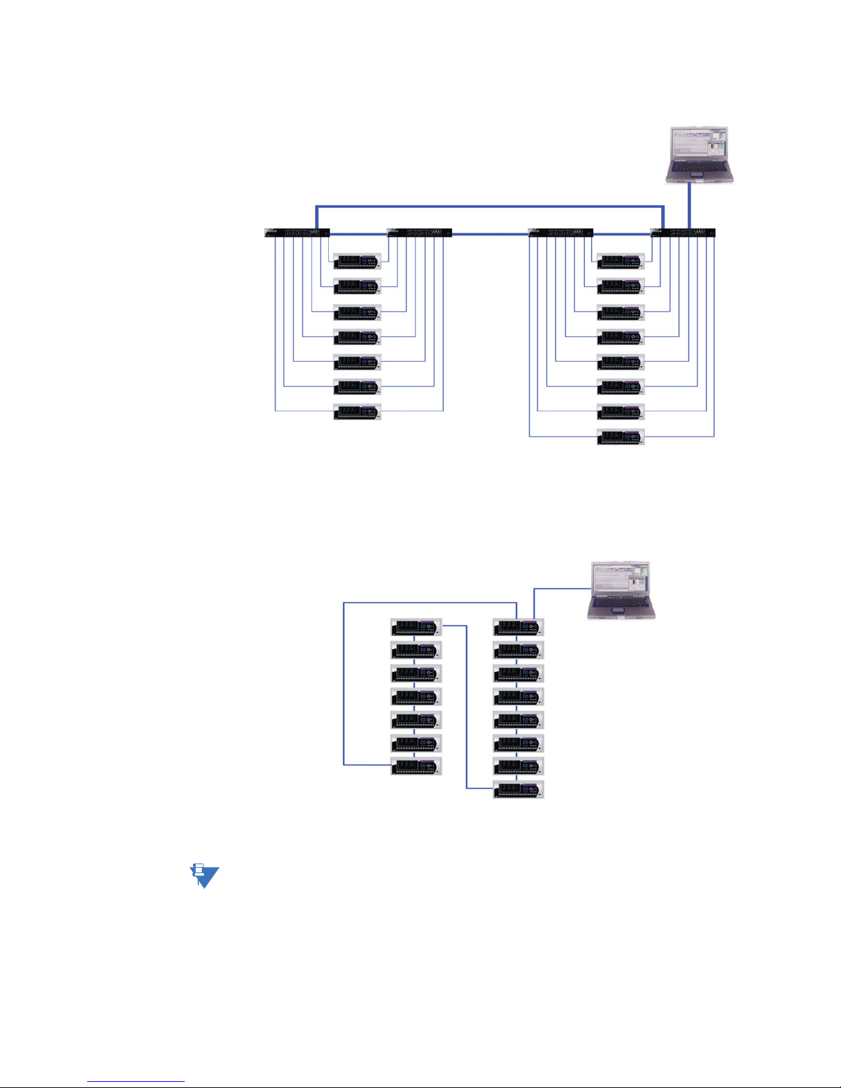
FIGURE QS–5: Traditional Redundant UR LAN Topology
.
FIGURE QS–6: Switch-enabled UR LAN Topology
Note
NOTE
• RSTP supports 16 switches in a Mess/Ring.
• RO Mode supports a maximum of 18 switches in a ring.
• With STP there is no limit.
QS–14 UR SWITCH MODULE – QUICKSTART GUIDE
Page 19

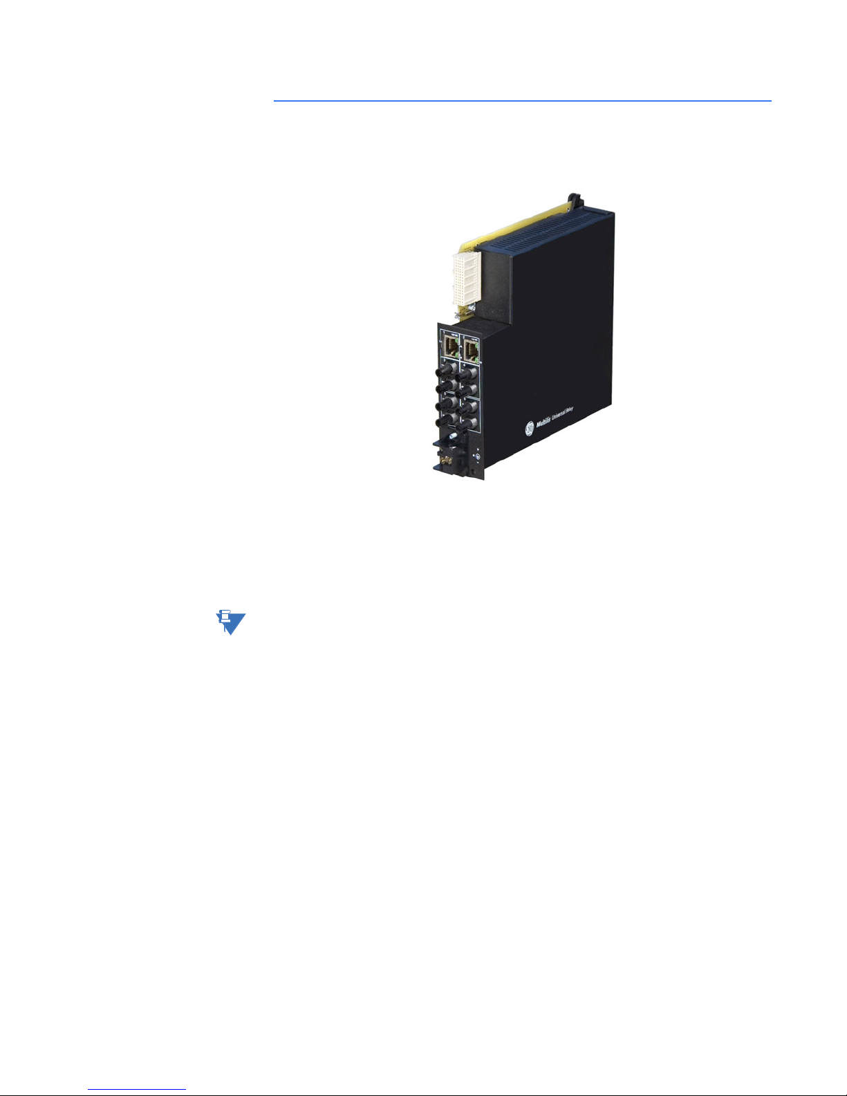
QS.4.1 Hardware Overview
The 2S and 2T managed Switch modules provide two 10/100 BaseT and four Multi-mode
ST 100 base Fx external Ethernet ports in addition to a serial console port .
QUICKSTART GUIDE
2 x 10/100BaseT Ports
4 x 100Mb FX multimode
ports with ST connectors
Independent Power Supply
Options: 2S - HI P/S
2T - LO P/S
FIGURE QS–7: Rear View Showing I/O Ports
QS.4.2 2S and 2T LED indicators
The function of the 2S and 2T Switch modules LED indicators is as shown below.
Copper ports have 3 LEDs indicating:
Fiber Ports have 1 LED indicating:
Table QS–8: Console Port Pin Assignment
Pin Signal Description
1 CD Carrier Detect (not used)
2 RXD Receive Data (input)
3 TXD Transmit Data (output)
4opennot used
5 GND Signal Ground
6 to 9 open not used
FIGURE QS–9: Front View Showing Console Port
1. 10 or 100 MB
2. Full or Half Duplex
3. Linkup and Activity
UR SWITCH MODULE – QUICKSTART GUIDE QS–15
1. Linkup and Activity
Page 20

QUICKSTART GUIDE
QS.4.3 Hardware Installation
With power removed, the Switch module is mounted into slot W and is then connected to a
suitable source of external power via the connector located on the back of the module.
XWVUT S PNML KJ H DGF BR
ON = Link Active
Flashing LED = Activity
ON = Link Active
Flashing LED = Activity
FIGURE QS–10: LED Functions
RATINGS:
ControlPower:
Transformer Management Relay
T60
TechnicalSupport:
Tel:(905) 294-6222
Fax:(905) 201-2098
abc abc abc abc abc
GEPower Management
http://www.ge.com/indsys/pm
ContactInputs:
ContactOutputs:
®
®
88-300VDC @ 35W / 77-265V AC @ 35VA
300VDC Max 10mA
StandardPilot Duty / 250V AC 7.5A
360VA Resistive / 125V DC Break
4A@ L/R = 40mS / 300W
Model:
Mods:
WiringDiagram:
Inst.Manual:
SerialNumber:
Firmware:
Mfg.Date:
Madein
Canada
T60D00HCHF8AH6AM6BP8BX7A
000
ZZZZZZ
D
MAZB98000029
D
1998/01/05
-MAAB97000099-
ON = 100Mbps
OFF = 10 Mbps
ON = Full Duplex
OFF = Half Duplex
a
b
1
1
2
2
3
3
4
4
5
5
6
6
7
7
8
8
a
b
1
1
2
2
3
3
4
4
5
5
6
6
7
7
8
8
- = Neutral or negative
+ = Line or positive
= Ground
QS–16 UR SWITCH MODULE – QUICKSTART GUIDE
FIGURE QS–11: Rear view of UR chassis
Page 21

QUICKSTART GUIDE
SWITCHGEAR
GROUND BUS
QS.4.4 initial Configuration Procedure
AC or DC
HEAVY COPPER CONDUCTOR
OR BRAIDED WIRE
B8a
B8b
B6a
F
S
I
U
L
R
T
G
E
R
E
B6b
+
-
-
HIGH
LOW
Control Power
B5b
+
UR SERIES
PROTECTION SYSTEM
FIGURE QS–12: UR Switch Module Wiring Diagram
NOTE:
14 gauge stranded
wire with suitable
disconnect devices
is recommended
AC or DC
GND
-
Optional UR-2S
or UR-2T
Switch Module
+
Ensure Switch is configured before connecting to network devices.
CAUTION
A suitable IP address and subnet mask must be assigned to both the Switch and the UR
relay for correct operation. The Switch has been shipped with a default IP address of
192.168.1.2 and a subnet mask of 255.255.255.0. Consult your network administrator to
determine if the default IP address, subnet mask or default gateway needs to be modified.
QS.4.5 Configuring the Switch IP Address and Subnet Mask using EnerVista UR Setup Software.
In our example configuration of both the Switch’s IP address and subnet mask must be
changed to 3.94.247.229 and 255.255.252.0 respectively. The IP address, subnet mask and
default gateway can be configured using either EnerVista UR Setup software, the Switch’s
Secure Web Management (SWM), or through the console port using CLI.
In this example EnerVista UR setup software will be used.
Z From the Product setup menu select Communications > Ethernet
Switch > Configure IP.
Z Enter the Switch’s MAC address (located on the module), IP address
that you want to set in the switch, and Subnet Mask.
UR SWITCH MODULE – QUICKSTART GUIDE QS–17
Page 22

QUICKSTART GUIDE
Z Select Save and after a short delay you should get a confirmation
that the switch has been successfully configured.
Once both the switch and UR’s IP address and Subnet Mask have been configured, power
must be cycled to both the switch and relay.
QS–18 UR SWITCH MODULE – QUICKSTART GUIDE
Page 23

QS.4.6 Assigning an IP Address to the UR Switch Module using the Console Port
DB9 Female to DB9 Female
Cable Pin-out
Pin 2 Pin 2
Pin 3 Pin 3
Pin 5 Pin 5
QUICKSTART GUIDE
The Switch has been shipped with a default IP address of 192.168.1.2 and a subnet mask of
255.255.255.0. Consult your network administrator to determine if the IP address, subnet
mask or default gateway needs to be modified. In our example test network, the
administrator has given us IP addresses ranging from 3.94.247.1 to 3.94.247.254 with a
subnet mask of 255.255.252.0.
UR SWITCH MODULE – QUICKSTART GUIDE QS–19
Page 24

QUICKSTART GUIDE
The console port must be connected to the computer’s serial port using a serial cable with
a pin-out as shown above. Note that both ends of the cable are terminated in a DB9 pin
female connector. Pins 5 of this cable are connected together while pin 2 at one end is
connected to pin 3 at the other end. Once you have connected the computer’s serial port
to the switch’s console port, you can launch Hyperterminal as shown below.
The Hyperterminal utility application is a convenient standard software tool that will be
used to configure the Switch. This program is found on most Windows-based operating
systems under Programs > Accessories > Communications > Hyperterminal.
QS–20 UR SWITCH MODULE – QUICKSTART GUIDE
Page 25

QUICKSTART GUIDE
Z Once the Hyperterminal application is launched you will need to
cancel Hyperterminal’s dial sequence by left mouse clicking on the
Cancel pushbutton. This will allow you to access Hyperterminal’s
configuration menus.
Z Select an icon and name to use for saving the new Hyperterminal
configuration.
UR SWITCH MODULE – QUICKSTART GUIDE QS–21
Page 26

QUICKSTART GUIDE
Z Select the computer’s serial port that is connected to the UR
Switch.
Z Select OK.
Z In the next window set the baud rate to 38400, data bits to 8, no
parity, one stop bit and set the flow control to none.
Z Click on the OK icon to attempt communication to the UR Switch.
QS–22 UR SWITCH MODULE – QUICKSTART GUIDE
Page 27

QUICKSTART GUIDE
Z Press the Enter key until the message Hit <Enter> to log into UR-
2S (or 2T) system is displayed.
Z Press the Enter key one more time to get the Login prompt.
Z Enter the login name manager and the default password
manager.
Once you are successfully logged in, the prompt will change to the
model number of the Switch to which you are connected, followed
by the pound (#) sign, indicating a successful login.
UR SWITCH MODULE – QUICKSTART GUIDE QS–23
Page 28

QUICKSTART GUIDE
A valid IP address and subnet mask can now be programmed into the Switch using the IP
config command as follows:
QS–24 UR SWITCH MODULE – QUICKSTART GUIDE
Z Type in “ipconfig ip=“.
Z Enter the IP address (in our example we will use a unique address
between 3.94.247.1 and 3.94.247.254), followed by a space.
Z Type in “mask=“ and enter the mask (in our example system we
would use 255.255.252.0).
Z If a default gateway is also required enter a space and type “dgw=“
Z Enter the IP address of the gateway, then select the enter key.
The switch will then indicate that the parameters have been set.
Z Save the settings using the Save command.
Page 29

QUICKSTART GUIDE
Z Reboot the switch using the Reboot command as shown.
Note when asked to save the current configuration enter Y for Yes.
Z Once the Switch has rebooted, you will need to login again.
Z To confirm that the IP address and subnet mask were saved
correctly enter the command “show setup” followed by the Enter
key.
The Switch will then provide an on-screen list of the switch’s
settings including the switch’s IP address and subnet mask, and, if
programmed, the default gateway.
Once you have verified that the IP, subnet mask and default
gateway settings are correct you can configure the Switch via the
web interface.
Z If the computer is already on a network, connect the Switch to the
network.
The next step is to test communications to the switch with the ping command:
Z From the command prompt type in PING 3.94.247.229.
Z Press the Enter key.
If communication is working correctly you should get a response from the Switch. If there is
a problem you will get four consecutive timeout error messages. If this occurs check the
media, ensure that the IP address subnet mask has been set correctly, and try again.
UR SWITCH MODULE – QUICKSTART GUIDE QS–25
Page 30

QUICKSTART GUIDE
Note
Given that the UR-2S/2T supports Autonegotiation, a straight-through or crossover cable
may be used to directly connect a PC to the Switch.
NOTE
Z If the computer isn’t connected to the network you will require a
straight-through or a crossover cable and will need to set up a
static IP address to test.
QS.4.7 Assigning a static IP Address to a personnel computer
The Switch can be completely configured using the console port (after configuration of the
IP address and subnet mask, the Switch can be configured using the WEB interface).
In order to configure the Switch using the web-based interface, the computer must be
assigned an IP address and subnet mask. If the computer has already been assigned an IP
address or is connected to a network such that the IP address will be automatically
assigned, you may proceed to configure the Switch through the web Interface.
Z Obtain an IP address, subnet mask, and possibly a gateway
address from your LAN Administrator.
There are rules associated with the assignment of these numbers
which go well beyond this introduction. As mentioned at the
beginning of this guide, for our test network we will be using a
subnet mask of 255.255.252.0 for all computers and relays on the
network.
The IP address of each device on the network must be unique.
Given that the switch was already assigned the IP address
3.94.247.229, we are left with 253 unique addresses.
Z Once the computer has booted up, right click on the icon labeled
“My Network Places”.
Z Select Properties.
QS–26 UR SWITCH MODULE – QUICKSTART GUIDE
Page 31

QUICKSTART GUIDE
Z Right mouse click on the "Local Area Connections" icon.
Z Select Properties.
UR SWITCH MODULE – QUICKSTART GUIDE QS–27
Page 32

QUICKSTART GUIDE
Z Locate and click on the Ethernet card (it will have TCPIP Protocol
as part of its name).
The Ethernet card is typically referred to as an Ethernet adaptor.
Z Select “Use the following IP address”.
Z Enter a unique IP address (from 3.94.247.001 to 3.94.247.254 if
using our test network address range).
Z Enter the subnet mask which, if using our test network, will be
255.255.252.0.).
Z Plug into the switch and ensure that the link LED comes on.
Z Select OK, then OK again to exit the LOCAL AREA NETWORK
PROPERTIES menu.
Z
QS–28 UR SWITCH MODULE – QUICKSTART GUIDE
Page 33

QUICKSTART GUIDE
Z Select Run.
Z Enter CMD to start the DOS shell.
Addresses now being used
Once the DOS shell has launched you will be presented with a DOS window.
Z At the DOS prompt enter the command “ipconfig” followed by the
Enter key.
This is the command that will cause the Ethernet adaptor to
immediately use the IP, and Subnet Mask addresses just
UR SWITCH MODULE – QUICKSTART GUIDE QS–29
Page 34

QUICKSTART GUIDE
programmed.
An on-screen report will appear indicating which addresses are
now being used by the adapter.
The computer’s configuration is complete.
Z Launch Internet Explorer and enter the IP address of the Switch in
order to go to the Switch’s web page.
Z At the switch’s login web page, enter the default Login name which
is “manager”.
Z Enter the default login Password which is again “manager”.
Z Left mouse click on the Login pushbutton to attempt to log in.
QS–30 UR SWITCH MODULE – QUICKSTART GUIDE
Page 35

QUICKSTART GUIDE
If you have successfully logged in you will be presented with a graphic of the particular
Switch to which you are connected.
QS.4.8 Self-test Errors and Meaning
Note
NOTE
Activation Setting (set to
"Enabled")
ETHERNET SWITCH FAIL
FUNCTION
Be sure to enable the Ethernet Switch Fail function under Product Setup > User-
Programmable Self-tests, and Port Events under Product Setup > Communications >
Ethernet Switch.
Event Name Event Cause Possible Causes
ETHERNET
MODULE OFFLINE
No response has been
received from the
Ethernet module after 5
successive polling
attempts.
• Loss of Switch power
•IP/Gateway/Subnet
incompatibility between
the CPU and the Switch
module.
• UR Port (Port 7) being
configured wrongly/
blocked
• Switch IP Address
assigned to another
device in the same
network.
PORT n EVENTS
UR SWITCH MODULE – QUICKSTART GUIDE QS–31
ETHERNET PORT n
OFFLINE
An active Ethernet port
has returned a “Failed”
status.
• Ethernet connection
broken.
• An inactive port’s events
have been enabled.
Page 36

QUICKSTART GUIDE
No setting required; the UR
will read the state of a
general purpose I/O port
on the main CPU upon
power-up and create the
error if there is a conflict
between the I/O state and
the order code.
EQUIPMENT
MISMATCH:
Card XXX Missing
The UR has not detected
the presence of the
Ethernet Switch via the
bus board.
Relay failed to see Switch
module on power-up, because
Switch won’t power up or is still
powering up. To clear fault,
cycle power to the UR Relay.
QS–32 UR SWITCH MODULE – QUICKSTART GUIDE
Page 37

QUICKSTART GUIDE
QS.5 Tagged VLAN’s
VLAN is short for virtual LAN. A VLAN creates separate network segments that can span
multiple switches. A VLAN is a group of ports designated by the switch as belonging to the
same broadcast domain. VLANs provide the capability of having multiple networks coexisting on the same switch. Separation of traffic and security are just two advantages of
VLANs.
VLANs can be port-based or tag-based. Port VLANs set a specific port or group of ports to
belong to a VLAN. When using tag-based VLANs, a tag - a "VLAN identifier" - is sent as part
of the message. This tag allows the message to move across multiple switches whose
ports are part of the same tagged VLAN. Note that the UR Port (Port 7), being the port
connected to the UR relay, must therefore be included in all VLANs from which the relay is
to receive or transmit data.
Background
The IEC 61850 Fixed GOOSE peer-to-peer communication service is an enhanced version
of IEC GSSE peer-to-peer service with the additional ability to assign a priority and a "tag"
to the multi-cast messages.
UR SWITCH MODULE – QUICKSTART GUIDE QS–33
Page 38
QUICKSTART GUIDE
QS.5.1 Configuring Tagged VLANs
VLAN 1
VLAN 2
Configuring a VLAN within the Switch
To configure a VLAN within the switch:
QS–34 UR SWITCH MODULE – QUICKSTART GUIDE
FIGURE QS–13: Tagged Virtual LANs
Z First determine which physical ports are to be part of the tag-
based VLAN.
Z Take note the names of the associated ports displayed on the
home page.
In our example we want the ports named A5 and A6 and A7 to be
part of the new VLAN.
Z Once the port names have been determined, open the main port
configuration page by double clicking on one of the port icons.
Page 39

QUICKSTART GUIDE
In this page we can see that the port named A5,A6 and A7 have been assigned port
number 5, 6 and 7 respectively. .
FIGURE QS–14: Associated Port Numbers; 7 is connected to the UR
Z Now open the VLANs menu and select the Type menu.
Z In this menu set the VLAN type to tag.
Z Select the Save icon.
SAVE
UR SWITCH MODULE – QUICKSTART GUIDE QS–35
Page 40

QUICKSTART GUIDE
We have now configured the Switch to support Tag-based VLANs
We can now proceed to the Tag-based VLAN menu . From the Tag-based VLAN menu we
can see that all ports have been assigned to default to Tag-based VLAN 1.
Z To create a new Tag-based VLAN click on the Add icon..
A screen will open that will allow you to configure a new Tag-based VLAN.
Within this screen:
QS–36 UR SWITCH MODULE – QUICKSTART GUIDE
Page 41

QUICKSTART GUIDE
Z Enter the new VLAN ID number (or tag) and the name of the VLAN.
We will use a tag of two and a VLAN name of GOOSE.
Z Left mouse-click on the check boxes corresponding to ports 5, 6
and 7 to add them to VLAN 2.
Z Select Save.
Z OK to exit.
You will notice below, that the status of the VLAN named GOOSE is displayed as Pending.
To activate VLAN 2 proceed as follows.
UR SWITCH MODULE – QUICKSTART GUIDE QS–37
Page 42

QUICKSTART GUIDE
Z Select Status.
Z Once in the Status menu, set the VLAN ID to 2 and the VLAN status
to start.
Z Select OK to start VLAN 2.
You will notice that VLAN 2 is now active.
Configure
QS–38 UR SWITCH MODULE – QUICKSTART GUIDE
Page 43

QUICKSTART GUIDE
You will notice that VLAN 2 is now active but the ports 5,6 and 7 have been removed from
the default tagged based VLAN1. You can add them back into the default tagged based
VLAN 1 if you wish such that they are part of both VLAN 1 and VLAN 2. To do this select the
configure ICON for the default tagged based VLAN1.
Z Add ports 5,6 and 7 to tagged based VLAN 1 by checking the
corresponding boxes.
Z Select the Save icon at the top of the screen then select OK to
return to the main tag VLAN menu.
Save
Note that ports 5, 6, and 7 are now part of both VLAN1 and VLAN 2.
You have now completed the exercise.
UR SWITCH MODULE – QUICKSTART GUIDE QS–39
Page 44

QUICKSTART GUIDE
QS.5.2 Configuring the UR Switch for Ring Only Mode
Note
By setting STP type to RSTP two choices of the span tree algorithm will be available: the
standard RSTP (Rapid Spanning Tree Protocol) or the high speed “Ring Only Mode”
NOTE
For information about RSTP setup, refer to the User Manual.
This feature can be used only when the Switches are connected to form a single ring
topology. This means that only two ports per Switch are used to form the ring; all other
ports will not be part of this ring or another ring. RO mode has typical recovery time of ≤ 5
ms/hop.
QS–40 UR SWITCH MODULE – QUICKSTART GUIDE
FIGURE QS–15: Configuration of UR Switch Ring-only Mode
Page 45

QUICKSTART GUIDE
.
Z from the Administration menu open the Set menu.
Z Open the STP type setting.
Z Set STP to Rapid Spanning Tree (RSTP).
UR SWITCH MODULE – QUICKSTART GUIDE QS–41
Z Save the setting.
Page 46

QUICKSTART GUIDE
.
Z From the configuration menu open the RSTP menu.
Z Select Bridge RSTP.
Note that the protocol is still set to normal RSTP.
Z Select the Edit icon.
QS–42 UR SWITCH MODULE – QUICKSTART GUIDE
Page 47

QUICKSTART GUIDE
Z Once in Edit mode, change the Status to Enabled
Z Once these settings have been completed Save the conf iguration.
...THEN SAVE
ENABLE STATUS...
UR SWITCH MODULE – QUICKSTART GUIDE QS–43
Page 48

QUICKSTART GUIDE
Z Once saved, select OK, then OK again to exit .
QS–44 UR SWITCH MODULE – QUICKSTART GUIDE
Page 49

QUICKSTART GUIDE
Z Select the Configuration > RSTP > RO Mode menu as shown
above.
Z Click the Edit button to configure RO Mode.
Z Select the desired ports that are part of the ring, as shown below.
Z Click OK to exit.
Note
NOTE
Only 2 ports can be selected to Ring Only Mode.
UR SWITCH MODULE – QUICKSTART GUIDE QS–45
Page 50

QUICKSTART GUIDE
Z Select the Enabled option for the Status setting as shown below.
...then Save
Enable status...
Z Change status to Enable.
Z Save the configuration by clicking on the icon.
Z For proper recovery, disable the Link Loss Alert function on all
ports forming the ring.
Z From the main port configuration menu left mouse click on the
Configuration Icon for each of these ports.
QS–46 UR SWITCH MODULE – QUICKSTART GUIDE
Page 51

QUICKSTART GUIDE
Z Within the Port Configuration screen ensure that the Link Loss
Alert is set to “Disabled”.
Z Save the settings.
Z Repeat this procedure for the other other port on each switch that
forms the ring.
FOR EVERY
SWITCH IN THE
RING, DISABLE
LLA ON PORTS
THAT ARE IN THE
RING
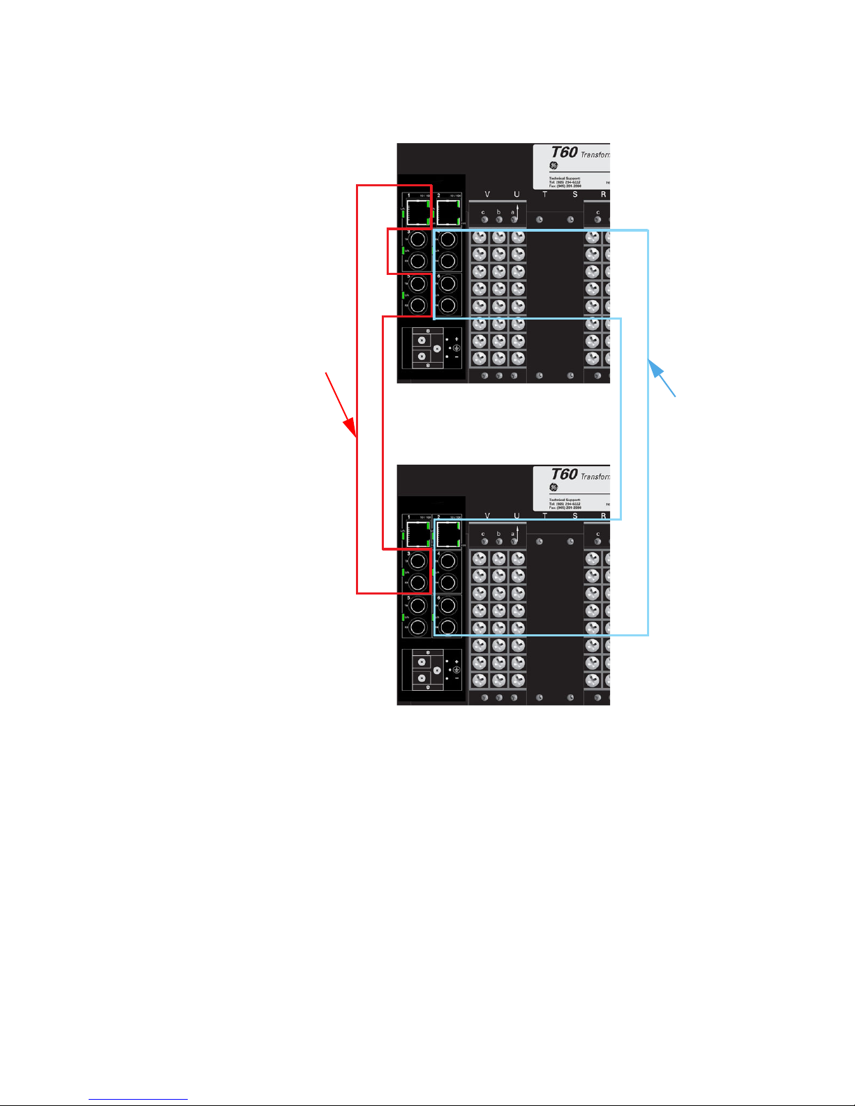
Z Once this procedure has been completed for all ports forming the
ring, connect the configured ports into the ring topology as shown
below.
UR SWITCH MODULE – QUICKSTART GUIDE QS–47
Page 52

QUICKSTART GUIDE
FIGURE QS–16: Configuration of the UR Switch Ring-only mode
You have completed configuration of Ring-only mode.
QS–48 UR SWITCH MODULE – QUICKSTART GUIDE
Page 53

QS.5.3 Saving and Loading Switch Settings
QUICKSTART GUIDE
Note
NOTE
Note
For other methods of transferring Settings Files, please refer to the UR Switch User Manual.
Saving Switch Settings
Switch Settings Files can be saved and loaded using EnerVista UR Setup, EnerVista
Multilink Software, or via the Console port (CLI). To save the Switch Settings File using
NOTE
EnerVista UR Setup, select Settings > Product Setup > Communications > Ethernet
Switch > Ethernet Switch Settings File.
Z Select the Retrieve Switch Settings Files option.
The following window will appear prompting you to select the
location and name of the Settings file to be saved.
Once the Save option is selected, the following window will pop up, indicating the Settings
file transfer is in progress.
Loading Switch Settings
Note
NOTE
UR SWITCH MODULE – QUICKSTART GUIDE QS–49
Place the Switch offline while transferring Setting Files to the Switch.
When transferring Settings Files from one Switch to another, the IP address of the
originating Switch will also be transferred. The user must therefore reset the IP address on
the receiving Switch before connecting to the network.
Page 54

QUICKSTART GUIDE
To Load the Switch settings file select Settings > Product Setup > Communications >
Ethernet Switch > Ethernet Switch Settings File > Transfer Settings File.
Z Click on the Transfer Settings File option.
The following window will pop-up, prompting you to select the location and file to be
loaded.
Once Open option is selected on the above window another pop-up window will appear as
shown below indicating setting file transfer is in progress.
If the Settings File transfer was successful, the window below will appear.
.
Note
NOTE
The switch will automatically reboot after a successful Settings File transfer
QS–50 UR SWITCH MODULE – QUICKSTART GUIDE
Page 55

QS.6 UR Switch Module Firmware Updates
QS.6.1 Updating UR Switch Module Firmware
This section describes the process for upgrading firmware on a UR-2S/T Switch Module.
There are several ways of updating Firmware on a UR Switch Module: EnerVista UR Setup
software, Serial using the UR Switch Module’s Console port, tftp or through ftp. It’s highly
recommended to use EnerVista UR Setup software to upgrade Firmware on a UR Switch
Module.
QUICKSTART GUIDE
Note
Firmware upgrade using serial, TFTP, and FTP, are described in the UR Switch Module
manual.
NOTE
QS.6.2 Selecting the Proper Version
The latest version of the firmware is available as a download from the GE Multilin web site.
To determine the version of firmware currently installed on your Switch, proceed as
follows:
Z Using the EnerVista web interface, log into the Switch using the
procedure described earlier. The firmware version installed on the
switch will appear on the lower left corner of the screen.
Version: 2.1beta
UR SWITCH MODULE – QUICKSTART GUIDE QS–51
Z Using the EnerVista UR Setup program, select Settings > Product
Setup > Communications > Ethernet Switch > Firmware Upload.
The following popup screen will appear warning that the settings
will be lost when the firmware is upgraded.
Page 56

QUICKSTART GUIDE
Note
It is highly recommended that you save the Switch settings before upgrading Switch
firmware.
NOTE
Z After saving the Settings file, proceed with the firmware upload by
selecting Yes to the above warning.
Another window will open, asking you to point to the location of the firmware file to be
uploaded.
Z Select the firmware file to be loaded on to the Switch, and select
the Open option.
The following window will pop up, indicating that the firmware file transfer is in progress.
QS–52 UR SWITCH MODULE – QUICKSTART GUIDE
Page 57

If the firmware load was successful, the following window will appear:.
QUICKSTART GUIDE
Note
NOTE
The switch will automatically reboot after a successful Settings File transfer.
Z Once the firmware has been successfully uploaded to the UR
Switch Module, load the Settings file using the procedure described
earlier.
UR SWITCH MODULE – QUICKSTART GUIDE QS–53
Page 58

QUICKSTART GUIDE
QS–54 UR SWITCH MODULE – QUICKSTART GUIDE
 Loading...