

Page 1

Title Page
IISO 9001
G
N
E
I
L
M
I
U
T
L
T
E
S
I
R
G
E
E
D
R
LISTED
52TL
IND.CONT. EQ.
E83849
GE
Digital Energy
B30 Bus Differential System
UR Series Instruction Manual
B30 revision: 5.9x
Manual P/N: 1601-0109-W2 (GEK-113371A)
GE Digital Energy
650 Markland Street
Markham, Ontario
Canada L6C 0M1
Tel: +1 905 927 7070 Fax: +1 905 927 5098
Internet: http://www.GEDigitalEnergy.com
*1601-0109-W2*
GE Multilin's Quality Management
System is registered to
ISO9001:2008
QMI # 005094
UL # A3775
Page 2

Copyright © 2015 GE Multilin Inc. All rights reserved.
B30 Bus Differential System UR Series Instruction Manual revision 5.9x.
FlexLogic, FlexElement, FlexCurve, FlexAnalog, FlexInteger, FlexState, EnerVista,
CyberSentry, HardFiber, Digital Energy, Multilin, and GE Multilin are trademarks
or registered trademarks of GE Multilin Inc.
The contents of this manual are the property of GE Multilin Inc. This
documentation is furnished on license and may not be reproduced in whole or
in part without the permission of GE Multilin. The content of this manual is for
informational use only and is subject to change without notice.
Part number: 1601-0109-W2 (August 2015)
Page 3

TABLE OF CONTENTS
0. BATTERY DISPOSAL 0.1 BATTERY DISPOSAL
1. GETTING STARTED 1.1 IMPORTANT PROCEDURES
1.1.1 CAUTIONS AND WARNINGS ........................................................................... 1-1
1.1.2 INSPECTION PROCEDURE ............................................................................. 1-1
1.2 UR OVERVIEW
1.2.1 INTRODUCTION TO THE UR ........................................................................... 1-2
1.2.2 HARDWARE ARCHITECTURE......................................................................... 1-3
1.2.3 UR SOFTWARE ARCHITECTURE ................................................................... 1-4
1.2.4 IMPORTANT UR CONCEPTS...........................................................................1-4
1.3 ENERVISTA UR SETUP SOFTWARE
1.3.1 REQUIREMENTS .............................................................................................. 1-5
1.3.2 SOFTWARE INSTALLATION ............................................................................ 1-5
1.3.3 CONFIGURING THE B30 FOR SOFTWARE ACCESS .................................... 1-7
1.3.4 USING THE QUICK CONNECT FEATURE....................................................... 1-9
1.3.5 CONNECTING TO THE B30 RELAY............................................................... 1-15
1.4 UR HARDWARE
1.4.1 MOUNTING AND WIRING............................................................................... 1-16
1.4.2 COMMUNICATIONS........................................................................................ 1-16
1.4.3 FACEPLATE DISPLAY.................................................................................... 1-16
1.5 USING THE RELAY
1.5.1 FACEPLATE KEYPAD..................................................................................... 1-17
1.5.2 MENU NAVIGATION ....................................................................................... 1-17
1.5.3 MENU HIERARCHY ........................................................................................ 1-17
1.5.4 RELAY ACTIVATION....................................................................................... 1-17
1.5.5 RELAY PASSWORDS..................................................................................... 1-18
1.5.6 FLEXLOGIC™ CUSTOMIZATION................................................................... 1-18
1.5.7 COMMISSIONING ........................................................................................... 1-19
2. PRODUCT DESCRIPTION 2.1 INTRODUCTION
2.1.1 OVERVIEW........................................................................................................ 2-1
2.1.2 ORDERING........................................................................................................ 2-3
2.1.3 REPLACEMENT MODULES ............................................................................. 2-8
2.2 SPECIFICATIONS
2.2.1 PROTECTION ELEMENTS ............................................................................. 2-10
2.2.2 USER-PROGRAMMABLE ELEMENTS........................................................... 2-11
2.2.3 MONITORING.................................................................................................. 2-12
2.2.4 METERING ...................................................................................................... 2-12
2.2.5 INPUTS ............................................................................................................2-13
2.2.6 POWER SUPPLY ............................................................................................ 2-14
2.2.7 OUTPUTS ........................................................................................................2-14
2.2.8 COMMUNICATIONS........................................................................................ 2-15
2.2.9 INTER-RELAY COMMUNICATIONS............................................................... 2-16
2.2.10 ENVIRONMENTAL .......................................................................................... 2-16
2.2.11 TYPE TESTS ................................................................................................... 2-17
2.2.12 PRODUCTION TESTS .................................................................................... 2-17
2.2.13 APPROVALS ................................................................................................... 2-18
2.2.14 MAINTENANCE ............................................................................................... 2-18
3. HARDWARE 3.1 DESCRIPTION
3.1.1 PANEL CUTOUT ............................................................................................... 3-1
3.1.2 MODULE WITHDRAWAL AND INSERTION ..................................................... 3-7
3.1.3 REAR TERMINAL LAYOUT............................................................................... 3-8
3.2 WIRING
3.2.1 TYPICAL WIRING............................................................................................ 3-10
GE Multilin B30 Bus Differential System iii
Page 4

TABLE OF CONTENTS
3.2.2 DIELECTRIC STRENGTH................................................................................3-11
3.2.3 CONTROL POWER..........................................................................................3-11
3.2.4 CT/VT MODULES.............................................................................................3-12
3.2.5 PROCESS BUS MODULES .............................................................................3-14
3.2.6 CONTACT INPUTS AND OUTPUTS................................................................3-14
3.2.7 TRANSDUCER INPUTS AND OUTPUTS........................................................3-22
3.2.8 RS232 FACEPLATE PORT..............................................................................3-24
3.2.9 CPU COMMUNICATION PORTS.....................................................................3-24
3.2.10 IRIG-B...............................................................................................................3-27
3.3 DIRECT INPUT AND OUTPUT COMMUNICATIONS
3.3.1 DESCRIPTION .................................................................................................3-29
3.3.2 FIBER: LED AND ELED TRANSMITTERS ......................................................3-31
3.3.3 FIBER-LASER TRANSMITTERS .....................................................................3-31
3.3.4 G.703 INTERFACE...........................................................................................3-32
3.3.5 RS422 INTERFACE .........................................................................................3-35
3.3.6 RS422 AND FIBER INTERFACE .....................................................................3-37
3.3.7 G.703 AND FIBER INTERFACE ......................................................................3-37
3.3.8 IEEE C37.94 INTERFACE................................................................................3-38
3.3.9 C37.94SM INTERFACE ...................................................................................3-41
4. HUMAN INTERFACES 4.1 ENERVISTA UR SETUP SOFTWARE INTERFACE
4.1.1 INTRODUCTION ................................................................................................4-1
4.1.2 CREATING A SITE LIST ....................................................................................4-1
4.1.3 ENERVISTA UR SETUP OVERVIEW................................................................4-1
4.1.4 ENERVISTA UR SETUP MAIN WINDOW..........................................................4-3
4.2 EXTENDED ENERVISTA UR SETUP FEATURES
4.2.1 SETTINGS TEMPLATES ...................................................................................4-5
4.2.2 SECURING AND LOCKING FLEXLOGIC™ EQUATIONS ................................4-9
4.2.3 SETTINGS FILE TRACEABILITY.....................................................................4-11
4.3 FACEPLATE INTERFACE
4.3.1 FACEPLATE.....................................................................................................4-14
4.3.2 LED INDICATORS............................................................................................4-15
4.3.3 CUSTOM LABELING OF LEDS .......................................................................4-18
4.3.4 DISPLAY...........................................................................................................4-23
4.3.5 KEYPAD ...........................................................................................................4-23
4.3.6 BREAKER CONTROL ......................................................................................4-23
4.3.7 MENUS.............................................................................................................4-24
4.3.8 CHANGING SETTINGS ...................................................................................4-25
5. SETTINGS 5.1 OVERVIEW
5.1.1 SETTINGS MENU ..............................................................................................5-1
5.1.2 INTRODUCTION TO ELEMENTS......................................................................5-4
5.1.3 INTRODUCTION TO AC SOURCES..................................................................5-5
5.2 PRODUCT SETUP
5.2.1 SECURITY..........................................................................................................5-8
5.2.2 DISPLAY PROPERTIES ..................................................................................5-13
5.2.3 CLEAR RELAY RECORDS ..............................................................................5-14
5.2.4 COMMUNICATIONS ........................................................................................5-15
5.2.5 MODBUS USER MAP ......................................................................................5-40
5.2.6 REAL TIME CLOCK .........................................................................................5-40
5.2.7 USER-PROGRAMMABLE FAULT REPORT....................................................5-41
5.2.8 OSCILLOGRAPHY ...........................................................................................5-42
5.2.9 USER-PROGRAMMABLE LEDS .....................................................................5-44
5.2.10 USER-PROGRAMMABLE SELF TESTS .........................................................5-48
5.2.11 CONTROL PUSHBUTTONS ............................................................................5-49
5.2.12 USER-PROGRAMMABLE PUSHBUTTONS....................................................5-50
5.2.13 FLEX STATE PARAMETERS ..........................................................................5-56
5.2.14 USER-DEFINABLE DISPLAYS........................................................................5-56
5.2.15 DIRECT INPUTS AND OUTPUTS....................................................................5-59
5.2.16 TELEPROTECTION .........................................................................................5-66
iv B30 Bus Differential System GE Multilin
Page 5

TABLE OF CONTENTS
5.2.17 INSTALLATION................................................................................................ 5-67
5.3 REMOTE RESOURCES
5.3.1 REMOTE RESOURCES CONFIGURATION ................................................... 5-68
5.4 SYSTEM SETUP
5.4.1 AC INPUTS ......................................................................................................5-69
5.4.2 POWER SYSTEM............................................................................................ 5-70
5.4.3 SIGNAL SOURCES ......................................................................................... 5-71
5.4.4 BREAKERS......................................................................................................5-74
5.4.5 DISCONNECT SWITCHES .............................................................................5-78
5.4.6 FLEXCURVES™..............................................................................................5-81
5.4.7 BUS.................................................................................................................. 5-88
5.5 FLEXLOGIC™
5.5.1 INTRODUCTION TO FLEXLOGIC™............................................................... 5-89
5.5.2 FLEXLOGIC™ RULES .................................................................................... 5-98
5.5.3 FLEXLOGIC™ EVALUATION.......................................................................... 5-98
5.5.4 FLEXLOGIC™ EXAMPLE ............................................................................... 5-98
5.5.5 FLEXLOGIC™ EQUATION EDITOR ............................................................. 5-103
5.5.6 FLEXLOGIC™ TIMERS................................................................................. 5-103
5.5.7 FLEXELEMENTS™ ....................................................................................... 5-104
5.5.8 NON-VOLATILE LATCHES ........................................................................... 5-108
5.6 GROUPED ELEMENTS
5.6.1 OVERVIEW.................................................................................................... 5-109
5.6.2 SETTING GROUP .........................................................................................5-109
5.6.3 BUS DIFFERENTIAL ..................................................................................... 5-110
5.6.4 PHASE CURRENT ........................................................................................ 5-114
5.6.5 NEUTRAL CURRENT.................................................................................... 5-124
5.6.6 GROUND CURRENT..................................................................................... 5-126
5.6.7 BREAKER FAILURE...................................................................................... 5-128
5.6.8 VOLTAGE ELEMENTS.................................................................................. 5-137
5.7 CONTROL ELEMENTS
5.7.1 OVERVIEW.................................................................................................... 5-142
5.7.2 TRIP BUS.......................................................................................................5-142
5.7.3 SETTING GROUPS ....................................................................................... 5-144
5.7.4 SELECTOR SWITCH..................................................................................... 5-145
5.7.5 DIGITAL ELEMENTS..................................................................................... 5-151
5.7.6 DIGITAL COUNTERS .................................................................................... 5-154
5.7.7 MONITORING ELEMENTS ........................................................................... 5-156
5.8 INPUTS AND OUTPUTS
5.8.1 CONTACT INPUTS........................................................................................ 5-165
5.8.2 VIRTUAL INPUTS.......................................................................................... 5-167
5.8.3 CONTACT OUTPUTS.................................................................................... 5-168
5.8.4 VIRTUAL OUTPUTS...................................................................................... 5-170
5.8.5 REMOTE DEVICES....................................................................................... 5-171
5.8.6 REMOTE INPUTS.......................................................................................... 5-172
5.8.7 REMOTE DOUBLE-POINT STATUS INPUTS .............................................. 5-173
5.8.8 REMOTE OUTPUTS...................................................................................... 5-173
5.8.9 RESETTING...................................................................................................5-174
5.8.10 DIRECT INPUTS AND OUTPUTS................................................................. 5-175
5.8.11 TELEPROTECTION INPUTS AND OUTPUTS.............................................. 5-179
5.8.12 IEC 61850 GOOSE ANALOGS...................................................................... 5-181
5.8.13 IEC 61850 GOOSE INTEGERS..................................................................... 5-182
5.9 TRANSDUCER INPUTS AND OUTPUTS
5.9.1 DCMA INPUTS .............................................................................................. 5-183
5.9.2 RTD INPUTS.................................................................................................. 5-184
5.9.3 DCMA OUTPUTS .......................................................................................... 5-186
5.10 TESTING
5.10.1 TEST MODE .................................................................................................. 5-189
5.10.2 FORCE CONTACT INPUTS .......................................................................... 5-190
5.10.3 FORCE CONTACT OUTPUTS ...................................................................... 5-191
GE Multilin B30 Bus Differential System v
Page 6

TABLE OF CONTENTS
6. ACTUAL VALUES 6.1 OVERVIEW
6.1.1 ACTUAL VALUES MAIN MENU.........................................................................6-1
6.2 STATUS
6.2.1 CONTACT INPUTS ............................................................................................6-3
6.2.2 VIRTUAL INPUTS ..............................................................................................6-3
6.2.3 REMOTE INPUTS ..............................................................................................6-3
6.2.4 REMOTE DOUBLE-POINT STATUS INPUTS...................................................6-4
6.2.5 TELEPROTECTION INPUTS .............................................................................6-4
6.2.6 CONTACT OUTPUTS ........................................................................................6-4
6.2.7 VIRTUAL OUTPUTS ..........................................................................................6-5
6.2.8 REMOTE DEVICES............................................................................................6-5
6.2.9 DIGITAL COUNTERS.........................................................................................6-6
6.2.10 SELECTOR SWITCHES ....................................................................................6-6
6.2.11 FLEX STATES....................................................................................................6-6
6.2.12 ETHERNET ........................................................................................................6-6
6.2.13 DIRECT INPUTS ................................................................................................6-7
6.2.14 DIRECT DEVICES STATUS ..............................................................................6-7
6.2.15 IEC 61850 GOOSE INTEGERS .........................................................................6-8
6.2.16 EGD PROTOCOL STATUS................................................................................6-8
6.2.17 TELEPROTECTION CHANNEL TESTS.............................................................6-9
6.3 METERING
6.3.1 METERING CONVENTIONS ...........................................................................6-10
6.3.2 BUS ZONE .......................................................................................................6-12
6.3.3 SOURCES ........................................................................................................6-12
6.3.4 TRACKING FREQUENCY................................................................................6-15
6.3.5 FLEXELEMENTS™..........................................................................................6-15
6.3.6 IEC 61580 GOOSE ANALOG VALUES ...........................................................6-16
6.3.7 TRANSDUCER INPUTS AND OUTPUTS........................................................6-16
6.4 RECORDS
6.4.1 USER-PROGRAMMABLE FAULT REPORTS .................................................6-17
6.4.2 EVENT RECORDS...........................................................................................6-17
6.4.3 OSCILLOGRAPHY ...........................................................................................6-17
6.5 PRODUCT INFORMATION
6.5.1 MODEL INFORMATION...................................................................................6-19
6.5.2 FIRMWARE REVISIONS..................................................................................6-19
7. COMMANDS AND
TARGETS
7.1 COMMANDS
7.1.1 COMMANDS MENU...........................................................................................7-1
7.1.2 VIRTUAL INPUTS ..............................................................................................7-1
7.1.3 CLEAR RECORDS.............................................................................................7-2
7.1.4 SET DATE AND TIME ........................................................................................7-2
7.1.5 RELAY MAINTENANCE.....................................................................................7-2
7.2 TARGETS
7.2.1 TARGETS MENU ...............................................................................................7-4
7.2.2 TARGET MESSAGES ........................................................................................7-4
7.2.3 RELAY SELF-TESTS .........................................................................................7-4
8. SECURITY 8.1 PASSWORD SECURITY
8.1.1 OVERVIEW ........................................................................................................8-1
8.1.2 PASSWORD SECURITY MENU ........................................................................8-2
8.1.3 LOCAL PASSWORDS........................................................................................8-2
8.1.4 REMOTE PASSWORDS ....................................................................................8-3
8.1.5 ACCESS SUPERVISION ...................................................................................8-4
8.1.6 DUAL PERMISSION SECURITY ACCESS........................................................8-4
8.2 SETTINGS SECURITY
8.2.1 SETTINGS TEMPLATES ...................................................................................8-6
8.2.2 SECURING AND LOCKING FLEXLOGIC™ EQUATIONS ..............................8-10
8.2.3 SETTINGS FILE TRACEABILITY.....................................................................8-12
vi B30 Bus Differential System GE Multilin
Page 7

TABLE OF CONTENTS
8.3 ENERVISTA SECURITY MANAGEMENT SYSTEM
8.3.1 OVERVIEW...................................................................................................... 8-15
8.3.2 ENABLING THE SECURITY MANAGEMENT SYSTEM................................. 8-15
8.3.3 ADDING A NEW USER ................................................................................... 8-15
8.3.4 MODIFYING USER PRIVILEGES ................................................................... 8-16
9. THEORY OF OPERATION 9.1 INTRODUCTION
9.1.1 BUS DIFFERENTIAL PROTECTION................................................................. 9-1
9.2 DYNAMIC BUS REPLICA
9.2.1 DYNAMIC BUS REPLICA MECHANISM........................................................... 9-2
9.2.2 CT RATIO MATCHING ...................................................................................... 9-3
9.3 DIFFERENTIAL PRINCIPLE
9.3.1 BIASED DIFFERENTIAL CHARACTERISTIC................................................... 9-4
9.3.2 DIFFERENTIAL AND RESTRAINING CURRENTS .......................................... 9-5
9.3.3 ENHANCED SECURITY.................................................................................... 9-6
9.4 DIRECTIONAL PRINCIPLE
9.4.1 CURRENT DIRECTIONAL PROTECTION ........................................................ 9-7
9.5 SATURATION DETECTOR
9.5.1 CT SATURATION DETECTION ........................................................................ 9-8
9.6 OUTPUT LOGIC AND EXAMPLES
9.6.1 OUTPUT LOGIC ................................................................................................ 9-9
9.6.2 INTERNAL AND EXTERNAL FAULT EXAMPLE .............................................. 9-9
10. APPLICATION OF
SETTINGS
10.1 OVERVIEW
10.1.1 INTRODUCTION.............................................................................................. 10-1
10.1.2 SAMPLE BUSBAR AND DATA........................................................................ 10-1
10.2 ZONING AND DYNAMIC BUS REPLICA
10.2.1 DESCRIPTION................................................................................................. 10-3
10.2.2 NORTH BUS ZONE ......................................................................................... 10-3
10.2.3 SOUTH BUS ZONE ......................................................................................... 10-4
10.3 BIASED CHARACTERISTIC BREAKPOINTS
10.3.1 DESCRIPTION................................................................................................. 10-5
10.3.2 HIGH BREAKPOINT ........................................................................................ 10-5
10.3.3 LOW BREAKPOINT......................................................................................... 10-6
10.4 SLOPES AND HIGH SET THRESHOLD
10.4.1 DESCRIPTION................................................................................................. 10-7
10.4.2 EXTERNAL FAULTS ON C-1 .......................................................................... 10-7
10.4.3 EXTERNAL FAULTS ON C-2 .......................................................................... 10-9
10.4.4 EXTERNAL FAULTS ON C-3 .......................................................................... 10-9
10.4.5 EXTERNAL FAULTS ON C-4 ........................................................................ 10-10
10.4.6 EXTERNAL FAULTS ON C-5 ........................................................................ 10-10
10.5 BUS DIFFERENTIAL SETTINGS
10.5.1 DESCRIPTION............................................................................................... 10-11
10.6 ENHANCING RELAY PERFORMANCE
10.6.1 USING SETTING GROUPS........................................................................... 10-12
11. MAINTENANCE 11.1 UNINSTALL AND CLEAR FILES AND DATA
11.1.1 UNINSTALL AND CLEAR FILES AND DATA.................................................. 11-1
11.2 REPAIRS
11.2.1 REPAIRS ......................................................................................................... 11-2
11.3 STORAGE
11.3.1 STORAGE........................................................................................................11-3
GE Multilin B30 Bus Differential System vii
Page 8

TABLE OF CONTENTS
11.4 DISPOSAL
11.4.1 DISPOSAL........................................................................................................11-4
A. FLEXANALOG AND
FLEXINTEGER
PARAMETERS
B. MODBUS
COMMUNICATIONS
C. IEC 61850
COMMUNICATIONS
A.1 PARAMETER LISTS
A.1.1 FLEXANALOG ITEMS....................................................................................... A-1
A.1.2 FLEXINTEGER ITEMS.................................................................................... A-10
B.1 MODBUS RTU PROTOCOL
B.1.1 INTRODUCTION ............................................................................................... B-1
B.1.2 PHYSICAL LAYER ............................................................................................ B-1
B.1.3 DATA LINK LAYER ........................................................................................... B-1
B.1.4 MODBUS RTU CRC-16 ALGORITHM ..............................................................B-2
B.2 MODBUS FUNCTION CODES
B.2.1 SUPPORTED FUNCTION CODES ................................................................... B-4
B.2.2 READ ACTUAL VALUES OR SETTINGS (FUNCTION CODE 03/04H) ...........B-4
B.2.3 EXECUTE OPERATION (FUNCTION CODE 05H)........................................... B-5
B.2.4 STORE SINGLE SETTING (FUNCTION CODE 06H)....................................... B-5
B.2.5 STORE MULTIPLE SETTINGS (FUNCTION CODE 10H)................................ B-6
B.2.6 EXCEPTION RESPONSES............................................................................... B-6
B.3 FILE TRANSFERS
B.3.1 OBTAINING RELAY FILES VIA MODBUS........................................................ B-7
B.4 MEMORY MAPPING
B.4.1 MODBUS MEMORY MAP ................................................................................. B-9
B.4.2 DATA FORMATS............................................................................................. B-60
C.1 OVERVIEW
C.1.1 INTRODUCTION ...............................................................................................C-1
C.1.2 COMMUNICATION PROFILES......................................................................... C-1
C.1.3 FILE TRANSFER BY IEC 61850.......................................................................C-2
C.2 SERVER DATA ORGANIZATION
C.2.1 OVERVIEW .......................................................................................................C-3
C.2.2 GGIO1: DIGITAL STATUS VALUES.................................................................C-3
C.2.3 GGIO2: DIGITAL CONTROL VALUES..............................................................C-3
C.2.4 GGIO3: DIGITAL STATUS AND ANALOG VALUES FROM RECEIVED GOOSE
DATAC-3
C.2.5 GGIO4: GENERIC ANALOG MEASURED VALUES.........................................C-3
C.2.6 MMXU: ANALOG MEASURED VALUES ..........................................................C-4
C.2.7 PROTECTION AND OTHER LOGICAL NODES............................................... C-4
C.3 SERVER FEATURES AND CONFIGURATION
C.3.1 BUFFERED/UNBUFFERED REPORTING........................................................C-6
C.3.2 FILE TRANSFER...............................................................................................C-6
C.3.3 TIMESTAMPS AND SCANNING....................................................................... C-6
C.3.4 LOGICAL DEVICE NAME .................................................................................C-6
C.3.5 LOCATION ........................................................................................................C-6
C.3.6 LOGICAL NODE NAME PREFIXES..................................................................C-7
C.3.7 CONNECTION TIMING.....................................................................................C-7
C.3.8 NON-IEC 61850 DATA...................................................................................... C-7
C.3.9 COMMUNICATION SOFTWARE UTILITIES.....................................................C-7
C.4 GENERIC SUBSTATION EVENT SERVICES: GSSE AND GOOSE
C.4.1 OVERVIEW .......................................................................................................C-8
C.4.2 GSSE CONFIGURATION..................................................................................C-8
C.4.3 FIXED GOOSE.................................................................................................. C-8
C.4.4 CONFIGURABLE GOOSE ................................................................................ C-8
C.4.5 ETHERNET MAC ADDRESS FOR GSSE/GOOSE ........................................ C-10
C.4.6 GSSE ID AND GOOSE ID SETTINGS............................................................C-11
viii B30 Bus Differential System GE Multilin
Page 9

TABLE OF CONTENTS
C.5 IEC 61850 IMPLEMENTATION VIA ENERVISTA UR SETUP
C.5.1 OVERVIEW......................................................................................................C-12
C.5.2 CONFIGURING IEC 61850 SETTINGS...........................................................C-13
C.5.3 ABOUT ICD FILES...........................................................................................C-14
C.5.4 CREATING AN ICD FILE WITH ENERVISTA UR SETUP ..............................C-18
C.5.5 ABOUT SCD FILES .........................................................................................C-18
C.5.6 IMPORTING AN SCD FILE WITH ENERVISTA UR SETUP...........................C-21
C.6 ACSI CONFORMANCE
C.6.1 ACSI BASIC CONFORMANCE STATEMENT.................................................C-23
C.6.2 ACSI MODELS CONFORMANCE STATEMENT ............................................C-23
C.6.3 ACSI SERVICES CONFORMANCE STATEMENT .........................................C-24
C.7 LOGICAL NODES
C.7.1 LOGICAL NODES TABLE ...............................................................................C-27
D. IEC 60870-5-104
COMMUNICATIONS
D.1 IEC 60870-5-104
D.1.1 INTEROPERABILITY DOCUMENT ...................................................................D-1
D.1.2 IEC 60870-5-104 POINTS .................................................................................D-9
E. DNP COMMUNICATIONS E.1 DEVICE PROFILE DOCUMENT
E.1.1 DNP V3.00 DEVICE PROFILE ..........................................................................E-1
E.1.2 IMPLEMENTATION TABLE............................................................................... E-4
E.2 DNP POINT LISTS
E.2.1 BINARY INPUT POINTS....................................................................................E-8
E.2.2 BINARY AND CONTROL RELAY OUTPUT......................................................E-9
E.2.3 COUNTERS .....................................................................................................E-10
E.2.4 ANALOG INPUTS ............................................................................................E-11
F. MISCELLANEOUS F.1 CHANGE NOTES
F.1.1 REVISION HISTORY ......................................................................................... F-1
F.1.2 CHANGES TO THE B30 MANUAL.................................................................... F-2
F.2 ABBREVIATIONS
F.2.1 STANDARD ABBREVIATIONS ....................................................................... F-11
F.3 WARRANTY
F.3.1 GE MULTILIN WARRANTY ............................................................................. F-14
INDEX
GE Multilin B30 Bus Differential System ix
Page 10

TABLE OF CONTENTS
x B30 Bus Differential System GE Multilin
Page 11

0 BATTERY DISPOSAL 0.1 BATTERY DISPOSAL
0 BATTERY DISPOSAL 0.1BATTERY DISPOSAL
EN Battery Disposal
This product contains a battery that cannot be disposed of as unsorted municipal waste in the European Union. See the product
documentation for specific battery information. The battery is marked with this symbol, which may include lettering to indicate cadmium
(Cd), lead (Pb), or mercury (Hg). For proper recycling return the battery to your supplier or to a designated collection point . For more
information see: www.recyclethis.info.
CS Nakládání s bateriemi
Tento produkt obsahuje baterie, které nemohou být zneškodněny v Evropské unii jako netříděný komunální odpadu. Viz dokumentace k
produktu pro informace pro konkrétní baterie. Baterie je označena tímto symbolem, který může zahrnovat i uvedena písmena, kadmium
(Cd), olovo (Pb), nebo rtuť (Hg). Pro správnou recyklaci baterií vraťte svémudodavateli nebo na určeném sběrném místě. Pro více informací
viz: www.recyclethis.info.
DA Batteri affald
Dette produkt indeholder et batteri som ikke kan bortskaffes sammen med almindeligt husholdningsaffald i Europa. Se
produktinformation for specifikke informationer om batteriet . Batteriet er forsynet med indgraveret symboler for hvad batteriet
indeholder: kadmium (Cd), bly (Pb) og kviksølv (Hg). Europæiske brugere af elektrisk udstyr skal aflevere kasserede produkter til genbrug
eller til leverandøren. Yderligere oplysninger findes på webstedet www.recyclethis.info.
DE Entsorgung von Batterien
Dieses Produkt beinhaltet eine Batterie, die nicht als unsortierter städtischer Abfall in der europäischen Union entsorgt werden darf.
Beachten Sie die spezifischen Batterie-informationen in der Produktdokumentation. Die Batterie ist mit diesem Symbol gekennzeichnet,
welches auch Hinweise auf möglicherweise enthaltene Stoffe wie Kadmium (Cd), Blei (Pb) oder Quecksilber (Hektogramm) darstellt. Für
die korrekte Wiederverwertung bringen Sie diese Batterie zu Ihrem lokalen Lieferanten zurück oder entsorgen Sie das Produkt an den
gekennzeichneten Sammelstellen. Weitere Informationen hierzu finden Sie auf der folgenden Website: www.recyclethis.info.
EL Απόρριψη μπαταριών
Αυτό το προϊόν περιέχει μια μπαταρία που δεν πρέπει να απορρίπτεται σε δημόσια συστήματα απόρριψης στην Ευρωπαϊκή
Κοινότητα. ∆είτε την τεκμηρίωση του προϊόντος για συγκεκριμένες πληροφορίες που αφορούν τη μπαταρία. Η μπαταρία είναι φέρει
σήμανση με αυτό το σύμβολο, το οποίο μπορεί να περιλαμβάνει γράμματα για να δηλώσουν το κάδμιο (Cd), τον
υδράργυρο (Hg). Για την κατάλληλη ανακύκλωση επιστρέψτε την μπαταρία στον προμηθευτή σας ή σε καθορισμένο σημείο συλλογής.
Για περισσότερες πληροφορίες δείτε: www.recyclethis.info.
μόλυβδο (Pb), ή τον
ES Eliminacion de baterias
Este producto contiene una batería que no se pueda eliminar como basura normal sin clasificar en la Unión Europea. Examine la
documentación del producto para la información específica de la batería. La batería se marca con este símbolo, que puede incluir siglas
para indicar el cadmio (Cd), el plomo (Pb), o el mercurio (Hg ). Para el reciclaje apropiado, devuelva este producto a su distribuidor ó
deshágase de él en los puntos de reciclaje designados. Para mas información : wwwrecyclethis.info.
ET Patareide kõrvaldamine
Käesolev toode sisaldab patareisid, mida Euroopa Liidus ei tohi kõrvaldada sorteerimata olmejäätmetena. Andmeid patareide kohta
vaadake toote dokumentatsioonist. Patareid on märgistatud käesoleva sümboliga, millel võib olla kaadmiumi (Cd), pliid (Pb) või
elavhõbedat (Hg) tähistavad tähed. Nõuetekohaseks ringlusse võtmiseks tagastage patarei tarnijale või kindlaksmääratud
vastuvõtupunkti. Lisainformatsiooni saab Internetist aadressil: www.recyclethis.info.
FI Paristoje ja akkujen hävittäminen
Tuote sisältää pariston, jota ei saa hävittää Euroopan Unionin alueella talousjätteen mukana. Tarkista tuoteselosteesta tuotteen tiedot.
Paristo on merkitty tällä symbolilla ja saattaa sisältää cadmiumia (Cd), lyijyä (Pb) tai elohopeaa (Hg). Oikean kierrätystavan
varmistamiseksi palauta tuote paikalliselle jälleenmyyjälle tai palauta se paristojen keräyspisteeseen. Lisätietoja sivuilla
www.recyclethis.info.
FR Élimination des piles
Ce produit contient une batterie qui ne peuvent être éliminés comme déchets municipaux non triés dans l'Union européenne. Voir la
documentation du produit au niveau des renseignements sur la pile. La batterie est marqué de ce symbole, qui comprennent les
indications cadmium (Cd), plomb (Pb), ou mercure (Hg). Pour le recyclage, retourner la batterie à votre fournisseur ou à un point de
collecte. Pour plus d'informations, voir: www.recyclethis.info.
HU Akkumulátor hulladék kezelése
Ezen termék akkumulátort tartalmaz, amely az Európai Unión belül csak a kijelölt módon és helyen dobható ki. A terméken illetve a
mellékelt ismertetőn olvasható a kadmium (Cd), ólom (Pb) vagy higany (Hg) tartalomra utaló betűjelzés. A hulladék akkumulátor leadható
a termék forgalmazójánál új akkumulátor vásárlásakor, vagy a kijelölt elektronikai hulladékudvarokban. További információ a
www.recyclethis.info oldalon.
0
GE Multilin B30 Bus Differential System xi
Page 12

0.1 BATTERY DISPOSAL 0 BATTERY DISPOSAL
IT Smaltimento batterie
Questo prodotto contiene una batteria che non può essere smaltita nei comuni contenitori per lo smaltimento rifiuti, nell' Unione
0
Europea. Controllate la documentazione del prodotto per le informazioni specifiche sulla batteria. La batteria è contrassegnata con
questo simbolo e può includere alcuni caratteri ad indicare la presenza di cadmio (Cd), piombo (Pb) oppure mercurio (Hg). Per il corretto
smaltimento, potete restituirli al vostro fornitore locale, oppure rivolgervi e consegnarli presso i centri di raccolta preposti. Per maggiori
informazioni vedere: ww.recyclethis.info.
LT Baterijų šalinimas
Šios įrangos sudėtyje yra baterijų, kurias draudžiama šalinti Europos Sąjungos viešose nerūšiuotų atliekų šalinimo sistemose. Informaciją
apie baterijas galite rasti įrangos techninėje dokumentacijoje. Baterijos žymimos šiuo simboliu, papildomai gali būti nurodoma kad
baterijų sudėtyje yra kadmio (Cd), švino (Pb) ar gyvsidabrio (Hg). Eksploatavimui nebetinkamas baterijas pristatykite į tam skirtas
surinkimo vietas arba grąžinkite jas tiesioginiam tiekėjui, kad jos būtų tinkamai utilizuotos. Daugiau informacijos rasite šioje interneto
svetainėje: www.recyclethis.info.
LV Bateriju likvidēšana
Šis produkts satur bateriju vai akumulatoru, kuru nedrīkst izmest Eiropas Savienībā esošajās sadzīves atkritumu sistēmās. Sk. produkta
dokumentācijā, kur ir norādīta konkrēta informācija par bateriju vai akumulatoru. Baterijas vai akumulatora marķējumā ir šis simbols,
kas var ietvert burtus, kuri norāda kadmiju (Cd), svinu (Pb) vai dzīvsudrabu (Hg). Pēc ekspluatācijas laika beigām baterijas vai akumulatori
jānodod piegādātājam vai specializētā bateriju savākšanas vietā. Sīkāku informāciju var iegūt vietnē: www.recyclethis.info.
NL Verwijderen van baterijen
Dit product bevat een batterij welke niet kan verwijdert worden via de gemeentelijke huisvuilscheiding in de Europese Gemeenschap.
Gelieve de product documentatie te controleren voor specifieke batterij informatie. De batterijen met deze label kunnen volgende
indictaies bevatten cadium (Cd), lood (Pb) of kwik (Hg). Voor correcte vorm van kringloop, geef je de producten terug aan jou locale
leverancier of geef het af aan een gespecialiseerde verzamelpunt. Meer informatie vindt u op de volgende website: www.recyclethis.info.
NO Retur av batteri
Dette produkt inneholder et batteri som ikke kan kastes med usortert kommunalt søppel i den Europeiske Unionen. Se
produktdokumentasjonen for spesifikk batteriinformasjon. Batteriet er merket med dette symbolet som kan inkludere symboler for å
indikere at kadmium (Cd), bly (Pb), eller kvikksølv (Hg) forekommer. Returner batteriet til leverandøren din eller til et dedikert
oppsamlingspunkt for korrekt gjenvinning. For mer informasjon se: www.recyclethis.info.
PL Pozbywanie się zużytych baterii
Ten produkt zawiera baterie, które w Unii Europejskiej mogą być usuwane tylko jako posegregowane odpady komunalne. Dokładne
informacje dotyczące użytych baterii znajdują się w dokumentacji produktu. Baterie oznaczone tym symbolem mogą zawierać
dodatkowe oznaczenia literowe wskazujące na zawartość kadmu (Cd), ołowiu (Pb) lub rtęci (Hg). Dla zapewnienia właściwej utylizacji,
należy zwrócić baterie do dostawcy albo do wyznaczonego punktu zbiórki. Więcej informacji można znaleźć na stronie internetowej
www.recyclethis.info.
PT Eliminação de Baterias
Este produto contêm uma bateria que não pode ser considerado lixo municipal na União Europeia. Consulte a documentação do
produto para obter informação específica da bateria. A bateria é identificada por meio de este símbolo, que pode incluir a rotulação
para indicar o cádmio (Cd), chumbo (Pb), ou o mercúrio (hg). Para uma reciclagem apropriada envie a bateria para o seu fornecedor ou
para um ponto de recolha designado. Para mais informação veja: www.recyclethis.info.
RU Утилизация батарей
Согласно европейской директиве об отходах электрического и электронного оборудования, продукты, содержащие батареи,
нельзя утилизировать как обычные отходы на территории ЕС. Более подробную информацию вы найдете в документации к
продукту. На этом символе могут присутствовать буквы, которые означают, что батарея собержит кадмий (Cd), свинец (Pb) или ртуть
(Hg). Для надлежащей утилизации по окончании срока
поставщику или сдать в специальный пункт приема. Подробности можно найти на веб-сайте: www.recyclethis.info.
эксплуатации пользователь должен возвратить батареи локальному
SK Zaobchádzanie s batériami
Tento produkt obsahuje batériu, s ktorou sa v Európskej únii nesmie nakladať ako s netriedeným komunálnym odpadom. Dokumentácia
k produktu obsahuje špecifické informácie o batérii. Batéria je označená týmto symbolom, ktorý môže obsahovať písmená na označenie
kadmia (Cd), olova (Pb), alebo ortuti (Hg). Na správnu recykláciu vráťte batériu vášmu lokálnemu dodávateľovi alebo na určené zberné
miesto. Pre viac informácii pozrite: www.recyclethis.info.
SL Odlaganje baterij
Ta izdelek vsebuje baterijo, ki je v Evropski uniji ni dovoljeno odstranjevati kot nesortiran komunalni odpadek. Za posebne informacije o
bateriji glejte dokumentacijo izdelka. Baterija je označena s tem simbolom, ki lahko vključuje napise, ki označujejo kadmij (Cd), svinec (Pb)
ali živo srebro (Hg). Za ustrezno recikliranje baterijo vrnite dobavitelju ali jo odstranite na določenem zbirališču. Za več informacij obiščite
spletno stran: www.recyclethis.info.
SV Kassering av batteri
Denna produkt innehåller ett batteri som inte får kastas i allmänna sophanteringssytem inom den europeiska unionen. Se
produktdokumentationen för specifik batteriinformation. Batteriet är märkt med denna symbol, vilket kan innebära att det innehåller
kadmium (Cd), bly (Pb) eller kvicksilver (Hg). För korrekt återvinning skall batteriet returneras till leverantören eller till en därför avsedd
deponering. För mer information, se: www.recyclethis.info.
xii B30 Bus Differential System GE Multilin
Page 13

0 BATTERY DISPOSAL 0.1 BATTERY DISPOSAL
TR Pil Geri Dönüşümü
Bu ürün Avrupa Birliği genel atık sistemlerine atılmaması gereken pil içermektedir. Daha detaylı pil bilgisi için ürünün kataloğunu
inceleyiniz. Bu sembolle işaretlenmiş piller Kadmiyum(Cd), Kurşun(Pb) ya da Civa(Hg) içerebilir. Doğru geri dönüşüm için ürünü yerel
tedarikçinize geri veriniz ya da özel işaretlenmiş toplama noktlarına atınız. Daha fazla bilgi için: www.recyclethis.info.
Global Contacts
North America 905-294-6222
Latin America +55 11 3614 1700
Europe, Middle East, Africa +(34) 94 485 88 00
Asia +86-21-2401-3208
India +91 80 41314617
From GE Part Number 1604-0021-A1, GE Publication Number GEK-113574
0
GE Multilin B30 Bus Differential System xiii
Page 14

0
0.1 BATTERY DISPOSAL 0 BATTERY DISPOSAL
xiv B30 Bus Differential System GE Multilin
Page 15

1 GETTING STARTED 1.1 IMPORTANT PROCEDURES
DANGER
WARNING
CAUTION
NOTICE
®
®
Model:
Mods:
Wiring Diagram:
Inst. Manual:
Serial Number:
Firmware:
Mfg. Date:
PO Num:
Item Num:
B30H00HCHF8HH6HM8AP6AU8AW6H
000
See manual
1601-0109
MAZB98000029
D
2012/01/05
600001234.56
Control Power:
Contact Inputs:
Contact Outputs:
88-300V DC @ 35W / 77-265V AC @ 35VA
300V DC Max 10mA
Refer to Instruction Manual
RATINGS:
B30
- M A A B 9 7 0 0 0 0 9 9 -
Bus Differential Relay
GE Multilin
- M A A B 9 7 0 0 0 0 9 9 -
LISTED
52TL
IND.CONT. EQ.
E83849
836781A3.CDR
NOTE
1 GETTING STARTED 1.1IMPORTANT PROCEDURES
Please read this chapter to help guide you through the initial setup of your new B30 Bus Differential System.
1.1.1 CAUTIONS AND WARNINGS
Before attempting to install or use the device, review all safety indicators in this document to help prevent injury, equipment
damage, or downtime.
The following safety and equipment symbols are used in this document.
Indicates a hazardous situation which, if not avoided, will result in death or serious injury.
Indicates a hazardous situation which, if not avoided, could result in death or serious injury.
Indicates a hazardous situation which, if not avoided, could result in minor or moderate
injury.
Indicates practices not related to personal injury.
1.1.2 INSPECTION PROCEDURE
1. Open the relay packaging and inspect the unit for physical damage.
2. View the rear nameplate and verify that the correct model has been ordered.
1
FIGURE 1–1: REAR NAMEPLATE (EXAMPLE)
3. Ensure that the following items are included:
• Instruction manual (if ordered)
• GE EnerVista CD (includes the EnerVista UR Setup software and manuals in PDF format)
• Mounting screws
For product information, instruction manual updates, and the latest software updates, please visit the GE Digital Energy
website.
If there is any noticeable physical damage, or any of the contents listed are missing, please contact GE
Multilin immediately.
GE MULTILIN CONTACT INFORMATION AND CALL CENTER FOR PRODUCT SUPPORT:
GE Digital Energy
650 Markland Street
Markham, Ontario
Canada L6C 0M1
TELEPHONE: Worldwide +1 905 927 7070
Europe/Middle East/Africa +34 94 485 88 54
North America toll-free 1 800 547 8629
FAX: +1 905 927 5098
E-MAIL: Worldwide multilin.tech@ge.com
Europe multilin.tech.euro@ge.com
HOME PAGE: http://www.gedigitalenergy.com/multilin
GE Multilin B30 Bus Differential System 1-1
Page 16

1.2 UR OVERVIEW 1 GETTING STARTED
1.2UR OVERVIEW 1.2.1 INTRODUCTION TO THE UR
1
Historically, substation protection, control, and metering functions were performed with electromechanical equipment. This
first generation of equipment was gradually replaced by analog electronic equipment, most of which emulated the singlefunction approach of their electromechanical precursors. Both of these technologies required expensive cabling and auxiliary equipment to produce functioning systems.
Recently, digital electronic equipment has begun to provide protection, control, and metering functions. Initially, this equipment was either single function or had very limited multi-function capability, and did not significantly reduce the cabling and
auxiliary equipment required. However, recent digital relays have become quite multi-functional, reducing cabling and auxiliaries significantly. These devices also transfer data to central control facilities and Human Machine Interfaces using electronic communications. The functions performed by these products have become so broad that many users now prefer the
term IED (Intelligent Electronic Device).
It is obvious to station designers that the amount of cabling and auxiliary equipment installed in stations can be even further
reduced, to 20% to 70% of the levels common in 1990, to achieve large cost reductions. This requires placing even more
functions within the IEDs.
Users of power equipment are also interested in reducing cost by improving power quality and personnel productivity, and
as always, in increasing system reliability and efficiency. These objectives are realized through software which is used to
perform functions at both the station and supervisory levels. The use of these systems is growing rapidly.
High speed communications are required to meet the data transfer rates required by modern automatic control and monitoring systems. In the near future, very high speed communications will be required to perform protection signaling with a
performance target response time for a command signal between two IEDs, from transmission to reception, of less than 3
milliseconds. This has been established by the IEC 61850 standard.
IEDs with the capabilities outlined above will also provide significantly more power system data than is presently available,
enhance operations and maintenance, and permit the use of adaptive system configuration for protection and control systems. This new generation of equipment must also be easily incorporated into automation systems, at both the station and
enterprise levels. The GE Multilin Universal Relay (UR) has been developed to meet these goals.
1-2 B30 Bus Differential System GE Multilin
Page 17

1 GETTING STARTED 1.2 UR OVERVIEW
827822A2.CDR
Input Elements
LAN
Programming
Device
Operator
Interface
Contact Inputs Contact Outputs
Virtual Inputs
Virtual Outputs
Analog Inputs
Analog Outputs
CT Inputs
VT Inputs
Input
Status
Table
Output
Status
Table
Pickup
Dropout
Operate
Protective Elements
Logic Gates
Remote Outputs
-DNA
-USER
CPU Module Output Elements
Remote Inputs
Direct Inputs
Direct Outputs
1.2.2 HARDWARE ARCHITECTURE
A) UR BASIC DESIGN
The UR is a digital-based device containing a central processing unit (CPU) that handles multiple types of input and output
signals. The UR can communicate over a local area network (LAN) with an operator interface, a programming device, or
another UR device.
FIGURE 1–2: UR CONCEPT BLOCK DIAGRAM
The CPU module contains firmware that provides protection elements in the form of logic algorithms, as well as programmable logic gates, timers, and latches for control features.
Input elements accept a variety of analog or digital signals from the field. The UR isolates and converts these signals into
logic signals used by the relay.
Output elements convert and isolate the logic signals generated by the relay into digital or analog signals that can be used
to control field devices.
1
B) UR SIGNAL TYPES
The contact inputs and outputs are digital signals associated with connections to hard-wired contacts. Both ‘wet’ and ‘dry’
contacts are supported.
The virtual inputs and outputs are digital signals associated with UR-series internal logic signals. Virtual inputs include
signals generated by the local user interface. The virtual outputs are outputs of FlexLogic™ equations used to customize
the device. Virtual outputs can also serve as virtual inputs to FlexLogic™ equations.
The analog inputs and outputs are signals that are associated with transducers, such as Resistance Temperature Detec-
tors (RTDs).
The CT and VT inputs refer to analog current transformer and voltage transformer signals used to monitor AC power lines.
The UR-series relays support 1 A and 5 A CTs.
The remote inputs and outputs provide a means of sharing digital point state information between remote UR-series
devices. The remote outputs interface to the remote inputs of other UR-series devices. Remote outputs are FlexLogic™
operands inserted into IEC 61850 GSSE and GOOSE messages.
The direct inputs and outputs provide a means of sharing digital point states between a number of UR-series IEDs over a
dedicated fiber (single or multimode), RS422, or G.703 interface. No switching equipment is required as the IEDs are connected directly in a ring or redundant (dual) ring configuration. This feature is optimized for speed and intended for pilotaided schemes, distributed logic applications, or the extension of the input/output capabilities of a single relay chassis.
GE Multilin B30 Bus Differential System 1-3
Page 18
1.2 UR OVERVIEW 1 GETTING STARTED
827823A1.CDR
PKP
DPO
OP
Protective Elements
Protection elements
serviced by sub-scan
Read Inputs
Solve Logic
Set Outputs
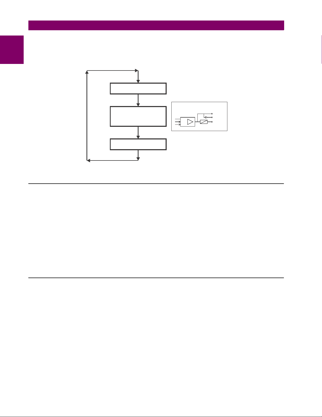
C) UR SCAN OPERATION
The UR-series devices operate in a cyclic scan fashion. The device reads the inputs into an input status table, solves the
1
logic program (FlexLogic™ equation), and then sets each output to the appropriate state in an output status table. Any
resulting task execution is priority interrupt-driven.
FIGURE 1–3: UR-SERIES SCAN OPERATION
1.2.3 UR SOFTWARE ARCHITECTURE
The firmware (software embedded in the relay) is designed in functional modules which can be installed in any relay as
required. This is achieved with object-oriented design and programming (OOD/OOP) techniques.
Object-oriented techniques involve the use of objects and classes. An object is defined as “a logical entity that contains
both data and code that manipulates that data”. A class is the generalized form of similar objects. By using this concept,
one can create a protection class with the protection elements as objects of the class, such as time overcurrent, instantaneous overcurrent, current differential, undervoltage, overvoltage, underfrequency, and distance. These objects represent
completely self-contained software modules. The same object-class concept can be used for metering, input/output control,
hmi, communications, or any functional entity in the system.
Employing OOD/OOP in the software architecture of the B30 achieves the same features as the hardware architecture:
modularity, scalability, and flexibility. The application software for any UR-series device (for example, feeder protection,
transformer protection, distance protection) is constructed by combining objects from the various functionality classes. This
results in a common look and feel across the entire family of UR-series platform-based applications.
1.2.4 IMPORTANT UR CONCEPTS
As described above, the architecture of the UR-series relays differ from previous devices. To achieve a general understanding of this device, some sections of Chapter 5 are quite helpful. The most important functions of the relay are contained in
“elements”. A description of the UR-series elements can be found in the Introduction to elements section in chapter 5.
Examples of simple elements, and some of the organization of this manual, can be found in the Control elements section of
chapter 5. An explanation of the use of inputs from CTs and VTs is in the Introduction to AC sources section in chapter 5. A
description of how digital signals are used and routed within the relay is contained in the Introduction to FlexLogic™ section
in chapter 5.
1-4 B30 Bus Differential System GE Multilin
Page 19

1 GETTING STARTED 1.3 ENERVISTA UR SETUP SOFTWARE
1.3ENERVISTA UR SETUP SOFTWARE 1.3.1 REQUIREMENTS
The faceplate keypad and display or the EnerVista UR Setup software interface can be used to communicate with the relay.
The EnerVista UR Setup software interface is the preferred method to edit settings and view actual values because the PC
monitor can display more information in a simple comprehensible format.
The following minimum requirements must be met for the EnerVista UR Setup software to properly operate on a PC.
• Pentium class or higher processor (Pentium II 300 MHz or higher recommended)
• Windows 95, 98, 98SE, ME, NT 4.0 (Service Pack 4 or higher), 2000, XP
• Internet Explorer 4.0 or higher
• 128 MB of RAM (256 MB recommended)
• 200 MB of available space on system drive and 200 MB of available space on installation drive
• Video capable of displaying 800 x 600 or higher in high-color mode (16-bit color)
• RS232 and/or Ethernet port for communications to the relay
The following qualified modems have been tested to be compliant with the B30 and the EnerVista UR Setup software.
• US Robotics external 56K FaxModem 5686
• US Robotics external Sportster 56K X2
• PCTEL 2304WT V.92 MDC internal modem
1.3.2 SOFTWARE INSTALLATION
After ensuring the minimum requirements for using EnerVista UR Setup are met (see previous section), use the following
procedure to install the EnerVista UR Setup from the enclosed GE EnerVista CD.
1. Insert the GE EnerVista CD into your CD-ROM drive.
2. Click the Install Now button and follow the installation instructions to install the no-charge EnerVista software.
3. When installation is complete, start the EnerVista Launchpad application.
4. Click the IED Setup section of the Launch Pad window.
1
GE Multilin B30 Bus Differential System 1-5
Page 20

1.3 ENERVISTA UR SETUP SOFTWARE 1 GETTING STARTED
5. In the EnerVista Launch Pad window, click the Add Product button and select the “B30 Bus Differential System” from
1
the Install Software window as shown below. Select the “Web” option to ensure the most recent software release, or
select “CD” if you do not have a web connection, then click the Add Now button to list software items for the B30.
6. EnerVista Launchpad will obtain the software from the Web or CD and automatically start the installation program.
7. Select the complete path, including the new directory name, where the EnerVista UR Setup will be installed.
8. Click on Next to begin the installation. The files will be installed in the directory indicated and the installation program
will automatically create icons and add EnerVista UR Setup to the Windows start menu.
9. Click Finish to end the installation. The UR-series device will be added to the list of installed IEDs in the EnerVista
Launchpad window, as shown below.
1-6 B30 Bus Differential System GE Multilin
Page 21

1 GETTING STARTED 1.3 ENERVISTA UR SETUP SOFTWARE
1.3.3 CONFIGURING THE B30 FOR SOFTWARE ACCESS
A) OVERVIEW
The user can connect remotely to the B30 through the rear RS485 port or the rear Ethernet port with a PC running the
EnerVista UR Setup software. The B30 can also be accessed locally with a computer through the front panel RS232 port or
the rear Ethernet port using the Quick Connect feature.
• To configure the B30 for remote access via the rear RS485 port(s), refer to the Configuring Serial Communications
section.
• To configure the B30 for remote access via the rear Ethernet port, refer to the Configuring Ethernet Communications
section. An Ethernet module must be specified at the time of ordering.
• To configure the B30 for local access with a computer through either the front RS232 port or rear Ethernet port, refer to
the Using the Quick Connect Feature section. An Ethernet module must be specified at the time of ordering for
Ethernet communications.
B) CONFIGURING SERIAL COMMUNICATIONS
Before starting, verify that the serial cable is properly connected to the RS485 terminals on the back of the device. The
faceplate RS232 port is intended for local use and is not described in this section; see the Using the Quick Connect Feature
section for details on configuring the RS232 port.
A computer with an RS232 port and a serial cable is required. To use the RS485 port at the back of the relay, a GE Multilin
F485 converter (or compatible RS232-to-RS485 converter) is required. See the F485 instruction manual for details.
1. Verify that the latest version of the EnerVista UR Setup software is installed (available from the GE EnerVista CD or
online from http://www.gedigitalenergy.com/multilin
2. Connect the computer to the F485 and the F485 to the RS485 terminal on the back of the UR device, or connect
directly the computer to the RS232 port on the front of the relay.
3. Select the “UR” device from the EnerVista Launchpad to start EnerVista UR Setup.
4. Click the Device Setup button to open the Device Setup window and click the Add Site button to define a new site.
5. Enter the desired site name in the “Site Name” field. If desired, a short description of site can also be entered along
with the display order of devices defined for the site. In this example, we will use “Location 1” as the site name. Click
the OK button when complete.
6. The new site will appear in the upper-left list in the EnerVista UR Setup window. Click the Device Setup button then
select the new site to re-open the Device Setup window.
7. Click the Add Device button to define the new device.
8. Enter the desired name in the “Device Name” field and a description (optional) of the site.
). See the Software Installation section for installation details.
1
GE Multilin B30 Bus Differential System 1-7
Page 22

1.3 ENERVISTA UR SETUP SOFTWARE 1 GETTING STARTED
9. Select “Serial” from the Interface drop-down list. This will display a number of interface parameters that must be
entered for proper serial communications.
1
FIGURE 1–4: CONFIGURING SERIAL COMMUNICATIONS
10. Enter the COM port used by the computer, the baud rate, and parity settings from the front panel
SETUP COMMUNICATIONS SERIAL PORTS menu, and the relay slave address setting from the front panel SETTINGS
PRODUCT SETUP COMMUNICATIONS MODBUS PROTOCOL MODBUS SLAVE ADDRESS menu in their respective
fields.
11. Click the Read Order Code button to connect to the B30 device and upload the order code. If an communications
error occurs, ensure that the EnerVista UR Setup serial communications values entered in the previous step
correspond to the relay setting values.
12. Click “OK” when the relay order code has been received. The new device will be added to the Site List window (or
Online window) located in the top left corner of the main EnerVista UR Setup window.
The Site Device has now been configured for RS232 communications. Proceed to the Connecting to the B30 section to
begin communications.
C) CONFIGURING ETHERNET COMMUNICATIONS
Before starting, verify that the Ethernet network cable is properly connected to the Ethernet port on the back of the relay. To
set up the relay for Ethernet communications, you define a Site, then add the relay as a Device at that site.The computer
and UR device must be on the same subnet.
1. Verify that the latest version of the EnerVista UR Setup software is installed (available from the GE EnerVista CD or
online from http://www.gedigitalenergy.com/multilin
2. Select the “UR” device from the EnerVista Launchpad to start EnerVista UR Setup.
3. Click the Device Setup button to open the Device Setup window, then click the Add Site button to define a new site.
4. Enter the desired site name in the “Site Name” field. If desired, a short description of site can also be entered along
with the display order of devices defined for the site. In this example, we will use “Location 2” as the site name. Click
the OK button when complete.
5. The new site will appear in the upper-left list in the EnerVista UR Setup window. Click the Device Setup button then
select the new site to re-open the Device Setup window.
6. Click the Add Device button to define the new device.
). See the Software Installation section for installation details.
SETTINGS PRODUCT
1-8 B30 Bus Differential System GE Multilin
Page 23

1 GETTING STARTED 1.3 ENERVISTA UR SETUP SOFTWARE
7. Enter the desired name in the “Device Name” field and a description (optional) of the site.
8. Select “Ethernet” from the Interface drop-down list. This will display a number of interface parameters that must be
entered for proper Ethernet functionality.
1
FIGURE 1–5: CONFIGURING ETHERNET COMMUNICATIONS
9. Enter the relay IP address specified in the front panel
NETWORK IP ADDRESS) in the “IP Address” field.
10. Enter the relay slave address and Modbus port address values from the respective settings in the front panel
PRODUCT SETUP COMMUNICATIONS MODBUS PROTOCOL menu.
11. Click the Read Order Code button to connect to the B30 device and upload the order code. If an communications
error occurs, ensure that the three EnerVista UR Setup values entered in the previous steps correspond to the relay
setting values.
12. Click OK when the relay order code has been received. The new device will be added to the Site List window (or
Online window) located in the top left corner of the main EnerVista UR Setup window.
The Site Device has now been configured for Ethernet communications. Proceed to the Connecting to the B30 section to
begin communications.
A) USING QUICK CONNECT VIA THE FRONT PANEL RS232 PORT
Before starting, verify that the serial cable is properly connected from the laptop computer to the front panel RS232 port
with a straight-through 9-pin to 9-pin RS232 cable.
1. Verify that the latest version of the EnerVista UR Setup software is installed (available from the GE EnerVista CD or
online from http://www.gedigitalenergy.com/multilin
2. Select the “UR” device from the EnerVista Launchpad to start EnerVista UR Setup.
). See the Software Installation section for installation details.
SETTINGS PRODUCT SETUP COMMUNICATIONS
SETTINGS
1.3.4 USING THE QUICK CONNECT FEATURE
GE Multilin B30 Bus Differential System 1-9
Page 24

1.3 ENERVISTA UR SETUP SOFTWARE 1 GETTING STARTED
842799A1.CDR
END 1 END 2
Pin Wire color Diagram Pin Wire color Diagram
1 White/orange 1 White/green
2 Orange 2 Green
3 White/green 3 White/orange
4 Blue 4 Blue
5 White/blue 5 White/blue
6 Green 6 Orange
7 White/brown 7 White/brown
8 Brown 8 Brown
1
2
3
4
5
6
7
8
3. Click the Quick Connect button to open the Quick Connect dialog box.
1
4. Select the Serial interface and the correct COM Port, then click Connect.
5. The EnerVista UR Setup software will create a site named “Quick Connect” with a corresponding device also named
“Quick Connect” and display them on the upper-left corner of the screen. Expand the sections to view data directly
from the B30 device.
Each time the EnerVista UR Setup software is initialized, click the Quick Connect button to establish direct communications to the B30. This ensures that configuration of the EnerVista UR Setup software matches the B30 model number.
B) USING QUICK CONNECT VIA THE REAR ETHERNET PORTS
To use the Quick Connect feature to access the B30 from a computer through Ethernet, first assign an IP address to the
relay from the front panel keyboard.
1. Press the MENU key until the SETTINGS menu is displayed.
2. Navigate to the
3. Enter an IP address of “1.1.1.1” and select the ENTER key to save the value.
4. In the same menu, select the
5. Enter a subnet IP address of “255.0.0.0” and press the ENTER key to save the value.
Next, use an Ethernet cross-over cable to connect the computer to the rear Ethernet port. The pinout for an Ethernet crossover cable is shown below.
SETTINGS PRODUCT SETUP COMMUNICATIONS NETWORK IP ADDRESS setting.
SUBNET IP MASK setting.
FIGURE 1–6: ETHERNET CROSS-OVER CABLE PIN LAYOUT
Now, assign the computer an IP address compatible with the relay’s IP address.
1-10 B30 Bus Differential System GE Multilin
Page 25

1 GETTING STARTED 1.3 ENERVISTA UR SETUP SOFTWARE
1. From the Windows desktop, right-click the My Network Places icon and select Properties to open the network con-
nections window.
2. Right-click the Local Area Connection icon and select Properties.
1
3. Select the Internet Protocol (TCP/IP) item from the list provided and click the Properties button.
4. Click on the “Use the following IP address” box.
GE Multilin B30 Bus Differential System 1-11
Page 26

1.3 ENERVISTA UR SETUP SOFTWARE 1 GETTING STARTED
5. Enter an IP address with the first three numbers the same as the IP address of the B30 relay and the last number
different (in this example, 1.1.1.2).
1
6. Enter a subnet mask equal to the one set in the B30 (in this example, 255.0.0.0).
7. Click OK to save the values.
Before continuing, it will be necessary to test the Ethernet connection.
1. Open a Windows console window by selecting Start > Run from the Windows Start menu and typing “cmd”.
2. Type the following command:
C:\WINNT>ping 1.1.1.1
3. If the connection is successful, the system will return four replies as follows:
Pinging 1.1.1.1 with 32 bytes of data:
Reply from 1.1.1.1: bytes=32 time<10ms TTL=255
Reply from 1.1.1.1: bytes=32 time<10ms TTL=255
Reply from 1.1.1.1: bytes=32 time<10ms TTL=255
Reply from 1.1.1.1: bytes=32 time<10ms TTL=255
Ping statistics for 1.1.1.1:
Packets: Sent = 4, Received = 4, Lost = 0 (0% loss),
Approximate round trip time in milli-seconds:
Minimum = 0ms, Maximum = 0ms, Average = 0 ms
4. Note that the values for time and TTL will vary depending on local network configuration.
If the following sequence of messages appears when entering the C:\WINNT>ping 1.1.1.1 command:
Pinging 1.1.1.1 with 32 bytes of data:
Request timed out.
Request timed out.
Request timed out.
Request timed out.
Ping statistics for 1.1.1.1:
Packets: Sent = 4, Received = 0, Lost = 4 (100% loss),
Approximate round trip time in milli-seconds:
Minimum = 0ms, Maximum = 0ms, Average = 0 ms
Pinging 1.1.1.1 with 32 bytes of data:
Verify the physical connection between the B30 and the laptop computer, and double-check the programmed IP address in
the PRODUCT SETUP COMMUNICATIONS NETWORK IP ADDRESS setting, then repeat step 2 in the above procedure.
If the following sequence of messages appears when entering the C:\WINNT>ping 1.1.1.1 command:
Pinging 1.1.1.1 with 32 bytes of data:
Hardware error.
Hardware error.
Hardware error.
Hardware error.
Ping statistics for 1.1.1.1:
Packets: Sent = 4, Received = 0, Lost = 4 (100% loss),
Approximate round trip time in milli-seconds:
Minimum = 0ms, Maximum = 0ms, Average = 0 ms
Pinging 1.1.1.1 with 32 bytes of data:
Verify the physical connection between the B30 and the laptop computer, and double-check the programmed IP address in
PRODUCT SETUP COMMUNICATIONS NETWORK IP ADDRESS setting, then repeat step 2 in the above procedure.
the
If the following sequence of messages appears when entering the
C:\WINNT>ping 1.1.1.1 command:
1-12 B30 Bus Differential System GE Multilin
Page 27

1 GETTING STARTED 1.3 ENERVISTA UR SETUP SOFTWARE
Pinging 1.1.1.1 with 32 bytes of data:
Destination host unreachable.
Destination host unreachable.
Destination host unreachable.
Destination host unreachable.
Ping statistics for 1.1.1.1:
Packets: Sent = 4, Received = 0, Lost = 4 (100% loss),
Approximate round trip time in milli-seconds:
Minimum = 0ms, Maximum = 0ms, Average = 0 ms
Pinging 1.1.1.1 with 32 bytes of data:
Verify the IP address is programmed in the local PC by entering the ipconfig command in the command window.
C:\WINNT>ipconfig
Windows 2000 IP Configuration
Ethernet adapter <F4FE223E-5EB6-4BFB-9E34-1BD7BE7F59FF>:
Connection-specific DNS suffix. . :
IP Address. . . . . . . . . . . . : 0.0.0.0
Subnet Mask . . . . . . . . . . . : 0.0.0.0
Default Gateway . . . . . . . . . :
Ethernet adapter Local Area Connection:
Connection-specific DNS suffix . :
IP Address. . . . . . . . . . . . : 1.1.1.2
Subnet Mask . . . . . . . . . . . : 255.0.0.0
Default Gateway . . . . . . . . . :
C:\WINNT>
It may be necessary to restart the laptop for the change in IP address to take effect (Windows 98 or NT).
Before using the Quick Connect feature through the Ethernet port, it is necessary to disable any configured proxy settings
in Internet Explorer.
1. Start the Internet Explorer software.
2. Select the Tools > Internet Options menu item and click on Connections tab.
3. Click on the LAN Settings button to open the following window.
1
4. Ensure that the “Use a proxy server for your LAN” box is not checked.
If this computer is used to connect to the Internet, re-enable any proxy server settings after the laptop has been disconnected from the B30 relay.
1. Verify that the latest version of the EnerVista UR Setup software is installed (available from the GE enerVista CD or
online from http://www.gedigitalenergy.com/multilin). See the Software Installation section for installation details.
2. Start the Internet Explorer software.
GE Multilin B30 Bus Differential System 1-13
Page 28

1.3 ENERVISTA UR SETUP SOFTWARE 1 GETTING STARTED
3. Select the “UR” device from the EnerVista Launchpad to start EnerVista UR Setup.
4. Click the Quick Connect button to open the Quick Connect dialog box.
1
5. Select the Ethernet interface and enter the IP address assigned to the B30, then click Connect.
6. The EnerVista UR Setup software will create a site named “Quick Connect” with a corresponding device also named
“Quick Connect” and display them on the upper-left corner of the screen. Expand the sections to view data directly
from the B30 device.
Each time the EnerVista UR Setup software is initialized, click the Quick Connect button to establish direct communications to the B30. This ensures that configuration of the EnerVista UR Setup software matches the B30 model number.
When direct communications with the B30 via Ethernet is complete, make the following changes:
1. From the Windows desktop, right-click the My Network Places icon and select Properties to open the network connections window.
2. Right-click the Local Area Connection icon and select the Properties item.
3. Select the Internet Protocol (TCP/IP) item from the list provided and click the Properties button.
4. Set the computer to “Obtain a relay address automatically” as shown below.
If this computer is used to connect to the Internet, re-enable any proxy server settings after the laptop has been disconnected from the B30 relay.
AUTOMATIC DISCOVERY OF ETHERNET DEVICES
The EnerVista UR Setup software can automatically discover and communicate to all UR-series IEDs located on an Ethernet network.
Using the Quick Connect feature, a single click of the mouse will trigger the software to automatically detect any UR-series
relays located on the network. The EnerVista UR Setup software will then proceed to configure all settings and order code
options in the Device Setup menu, for the purpose of communicating to multiple relays. This feature allows the user to
identify and interrogate, in seconds, all UR-series devices in a particular location.
1-14 B30 Bus Differential System GE Multilin
Page 29

1 GETTING STARTED 1.3 ENERVISTA UR SETUP SOFTWARE
842743A3.CDR
Communications status indicators:
Green = OK
Red = No communications
UR icon = report is open
Quick action hot links
Expand the site list by double-clicking
or selecting the +/– box.
NOTE
1.3.5 CONNECTING TO THE B30 RELAY
When unable to connect because of an "ACCESS VIOLATION," access Device Setup and refresh the order code for the
device.
1. Open the Display Properties window through the Site List tree as shown below:
1
2. The Display Properties window will open with a status indicator on the lower left of the EnerVista UR Setup window.
3. If the status indicator is red, verify that the Ethernet network cable is properly connected to the Ethernet port on the
back of the relay and that the relay has been properly setup for communications (steps A and B earlier).
If a relay icon appears in place of the status indicator, than a report (such as an oscillography or event record) is open.
Close the report to re-display the green status indicator.
4. The Display Properties settings can now be edited, printed, or changed according to user specifications.
Refer to chapter 4 in this manual and the EnerVista UR Setup Help File for more information about the
using the EnerVista UR Setup software interface.
QUICK ACTION HOT LINKS
The EnerVista UR Setup software has several new quick action buttons that provide users with instant access to several
functions that are often performed when using B30 relays. From the online window, users can select which relay to interrogate from a pull-down window, then click on the button for the action they wish to perform. The following quick action functions are available:
• View the B30 event record.
• View the last recorded oscillography record.
• View the status of all B30 inputs and outputs.
• View all of the B30 metering values.
• View the B30 protection summary.
GE Multilin B30 Bus Differential System 1-15
Page 30

1.4 UR HARDWARE 1 GETTING STARTED
EnerVista
Ethernet
10/100 Mbps
Regional
control
center
Modem
Remote
communications link
Local
control
Engineer
GE Multilin F485
communications converter
UR-series IED
Troubleshooting
Commissioning
Setting changes
Reports
RS485 115 kbps
RS232
EnerVista
EnerVista
842759A2.CDR
1.4UR HARDWARE 1.4.1 MOUNTING AND WIRING
1
Please refer to Chapter 3: Hardware for detailed mounting and wiring instructions. Review all WARNINGS and CAUTIONS
carefully.
1.4.2 COMMUNICATIONS
The EnerVista UR Setup software communicates to the relay via the faceplate RS232 port or the rear panel RS485 / Ethernet ports. To communicate via the faceplate RS232 port, a standard straight-through serial cable is used. The DB-9 male
end is connected to the relay and the DB-9 or DB-25 female end is connected to the PC COM1 or COM2 port as described
in the CPU communications ports section of chapter 3.
FIGURE 1–7: RELAY COMMUNICATIONS OPTIONS
To communicate through the B30 rear RS485 port from a PC RS232 port, the GE Multilin RS232/RS485 converter box is
required. This device (catalog number F485) connects to the computer using a “straight-through” serial cable. A shielded
twisted-pair (20, 22, or 24 AWG) connects the F485 converter to the B30 rear communications port. The converter terminals (+, –, GND) are connected to the B30 communication module (+, –, COM) terminals. Refer to the CPU communica-
tions ports section in chapter 3 for option details. The line should be terminated with an R-C network (that is, 120 Ω, 1 nF)
as described in the chapter 3.
1.4.3 FACEPLATE DISPLAY
All messages are displayed on a 2 × 20 backlit liquid crystal display (LCD) to make them visible under poor lighting conditions. While the keypad and display are not actively being used, the display will default to user-defined messages. Any high
priority event driven message will automatically override the default message and appear on the display.
1-16 B30 Bus Differential System GE Multilin
Page 31

1 GETTING STARTED 1.5 USING THE RELAY
1.5USING THE RELAY 1.5.1 FACEPLATE KEYPAD
Display messages are organized into pages under the following headings: actual values, settings, commands, and targets.
The MENU key navigates through these pages. Each heading page is broken down further into logical subgroups.
The MESSAGE keys navigate through the subgroups. The VALUE keys scroll increment or decrement numerical setting
values when in programming mode. These keys also scroll through alphanumeric values in the text edit mode. Alternatively, values may also be entered with the numeric keypad.
The decimal key initiates and advance to the next character in text edit mode or enters a decimal point. The HELP key may
be pressed at any time for context sensitive help messages. The ENTER key stores altered setting values.
1.5.2 MENU NAVIGATION
Press the MENU key to select the desired header display page (top-level menu). The header title appears momentarily followed by a header display page menu item. Each press of the MENU key advances through the following main heading
pages:
• Actual values.
• Settings.
• Commands.
• Targets.
• User displays (when enabled).
1.5.3 MENU HIERARCHY
The setting and actual value messages are arranged hierarchically. The header display pages are indicated by double
scroll bar characters (), while sub-header pages are indicated by single scroll bar characters (). The header display
pages represent the highest level of the hierarchy and the sub-header display pages fall below this level. The MESSAGE
UP and DOWN keys move within a group of headers, sub-headers, setting values, or actual values. Continually pressing
the MESSAGE RIGHT key from a header display displays specific information for the header category. Conversely, continually pressing the MESSAGE LEFT key from a setting value or actual value display returns to the header display.
1
HIGHEST LEVEL LOWEST LEVEL (SETTING VALUE)
SETTINGS
PRODUCT SETUP
SETTINGS
SYSTEM SETUP
The relay is defaulted to the “Not Programmed” state when it leaves the factory. This safeguards against the installation of
a relay whose settings have not been entered. When powered up successfully, the Trouble LED will be on and the In Service LED off. The relay in the “Not Programmed” state will block signaling of any output relay. These conditions will remain
until the relay is explicitly put in the “Programmed” state.
Select the menu message
RELAY SETTINGS:
Not Programmed
SETTINGS PRODUCT SETUP INSTALLATION RELAY SETTINGS
SECURITY
ACCESS LEVEL:
Restricted
1.5.4 RELAY ACTIVATION
GE Multilin B30 Bus Differential System 1-17
Page 32

1.5 USING THE RELAY 1 GETTING STARTED
NOTE
To put the relay in the “Programmed” state, press either of the VALUE keys once and then press ENTER. The faceplate
Trouble LED will turn off and the In Service LED will turn on. The settings for the relay can be programmed manually (refer
1
to Chapter 5) via the faceplate keypad or remotely (refer to the EnerVista UR Setup help file) via the EnerVista UR Setup
software interface.
1.5.5 RELAY PASSWORDS
It is recommended that passwords be set up for each security level and assigned to specific personnel. There are two user
password security access levels, COMMAND and SETTING:
1. COMMAND
The COMMAND access level restricts the user from making any settings changes, but allows the user to perform the following operations:
• change state of virtual inputs
• clear event records
• clear oscillography records
• operate user-programmable pushbuttons
2. SETTING
The SETTING access level allows the user to make any changes to any of the setting values.
Refer to the Changing Settings section in Chapter 4 for complete instructions on setting up security level
passwords.
1.5.6 FLEXLOGIC™ CUSTOMIZATION
FlexLogic™ equation editing is required for setting up user-defined logic for customizing the relay operations. See the FlexLogic™ section in Chapter 5 for additional details.
1-18 B30 Bus Differential System GE Multilin
Page 33

1 GETTING STARTED 1.5 USING THE RELAY
1.5.7 COMMISSIONING
The B30 requires a minimum amount of maintenance when it is commissioned into service. Since the B30 is a microprocessor-based relay, its characteristics do not change over time. As such, no further functional tests are required. Expected
service life is 20 years for UR devices manufactured June 2014 or later when applied in a controlled indoors environment
and electrical conditions within specification.
Furthermore, the B30 performs a number of continual self-tests and takes the necessary action in case of any major errors
(see the Relay Self-tests section in chapter 7 for details). However, it is recommended that B30 maintenance be scheduled
with other system maintenance. This maintenance may involve the in-service, out-of-service, or unscheduled maintenance.
In-service maintenance:
1. Visual verification of the analog values integrity such as voltage and current (in comparison to other devices on the corresponding system).
2. Visual verification of active alarms, relay display messages, and LED indications.
3. LED test.
4. Visual inspection for any damage, corrosion, dust, or loose wires.
5. Event recorder file download with further events analysis.
Out-of-service maintenance:
1. Check wiring connections for firmness.
2. Analog values (currents, voltages, RTDs, analog inputs) injection test and metering accuracy verification. Calibrated
test equipment is required.
3. Protection elements setting verification (analog values injection or visual verification of setting file entries against relay
settings schedule).
4. Contact inputs and outputs verification. This test can be conducted by direct change of state forcing or as part of the
system functional testing.
5. Visual inspection for any damage, corrosion, or dust.
6. Event recorder file download with further events analysis.
7. LED Test and pushbutton continuity check.
Unscheduled maintenance such as during a disturbance causing system interruption:
1. View the event recorder and oscillography or fault report for correct operation of inputs, outputs, and elements.
If it is concluded that the relay or one of its modules is of concern, contact GE Multilin for prompt service.
1
GE Multilin B30 Bus Differential System 1-19
Page 34

1
1.5 USING THE RELAY 1 GETTING STARTED
1-20 B30 Bus Differential System GE Multilin
Page 35

2 PRODUCT DESCRIPTION 2.1 INTRODUCTION
2 PRODUCT DESCRIPTION 2.1INTRODUCTION 2.1.1 OVERVIEW
The B30 Bus Differential System is a microprocessor based relay that provides protection and metering for a busbar with
up to six feeders. Protection is provided by a low impedance percent differential element with features that make it immune
to CT saturation. Both biased (restrained) and unbiased (unrestrained) differential protection functions are provided.
A dynamic busbar replica mechanism is provided by associating the breaker and switch status signals with the differential
zone currents.
The biased bus differential function operates using both the differential and current directional comparison protection principles. The differential element uses a dual-slope dual-breakpoint characteristic with the restraining current formed as a maximum of the input currents for better stability during through-fault conditions and faster operation on internal faults. The
current directional comparison principle checks the angular relationship between the currents.
The biased bus differential protection operates in the two-out-of-two mode for low differential currents. This improves stability during CT saturation conditions caused by comparatively low currents combined with unfavorable phenomena such as
multiple auto-reclose actions. For high differential currents, the bus differential element operates using the differential characteristic alone if CT saturation is not detected. Upon CT saturation detection, the relay switches to the two-out-of-two
operating mode for better through fault stability.
The B30 typical operating time is about 12 ms for fast form-C output contacts and internal usage by user-programmable
logic, and about 15 ms for trip-rated form-A output contacts.
A CT failure alarm function that monitors the level of the differential current is provided. A situation when the differential current stays above a pre-defined level for a pre-defined period of time is declared as a CT trouble event, and an alarm is
raised. To prevent false tripping due to CT trouble, undervoltage supervision or an external check zone can be used.
Voltage and current metering is built into the relay as a standard feature. Current parameters are available as total waveform RMS magnitude, or as fundamental frequency only RMS magnitude and angle (phasor).
Diagnostic features include an event recorder capable of storing 1024 time-tagged events and oscillography capable of
storing up to 64 records with programmable trigger, content and sampling rate.The internal clock used for time-tagging can
be synchronized with an IRIG-B signal or via the SNTP protocol over the Ethernet port. This precise time stamping allows
the sequence of events to be determined throughout the system. Events can also be programmed (via FlexLogic™ equations) to trigger oscillography data capture which may be set to record the measured parameters before and after the event
for viewing on a personal computer (PC). These tools significantly reduce troubleshooting time and simplify report generation in the event of a system fault.
A faceplate RS232 port may be used to connect to a PC for the programming of settings and the monitoring of actual values. A variety of communications modules are available. Two rear RS485 ports allow independent access by operating and
engineering staff. All serial ports use the Modbus
®
RTU protocol. The RS485 ports may be connected to system computers
with baud rates up to 115.2 kbps. The RS232 port has a fixed baud rate of 19.2 kbps. Optional communications modules
include a 10Base-F Ethernet interface which can be used to provide fast, reliable communications in noisy environments.
Another option provides two 10Base-F fiber optic ports for redundancy. The Ethernet port supports IEC 61850, Modbus
TCP, and TFTP protocols, and allows access to the relay via any standard web browser (B30 web pages). The IEC 608705-104 protocol is supported on the Ethernet port. DNP 3.0 and IEC 60870-5-104 cannot be enabled at the same time.
Settings and actual values can be accessed from the front panel or EnerVista software.
The B30 IEDs use flash memory technology which allows field upgrading as new features are added. The following Single
line diagram illustrates the relay functionality using ANSI (American National Standards Institute) device numbers.
2
®
/
Table 2–1: ANSI DEVICE NUMBERS AND FUNCTIONS
DEVICE
NUMBER
27P Phase undervoltage 51G Ground time overcurrent
50BF Breaker failure 51N Neutral time overcurrent
50G Ground instantaneous overcurrent 51P Phase time overcurrent
50N Neutral instantaneous overcurrent 59N Neutral overvoltage
50P Phase instantaneous overcurrent 59X Auxiliary overvoltage
50/74 CT trouble 87B Restrained bus differential
50/87 Unrestrained bus differential
FUNCTION DEVICE
NUMBER
FUNCTION
GE Multilin B30 Bus Differential System 2-1
Page 36

2
$(&'5
3
1
%UHDNHUSRVLWLRQDQGWULS
0HWHULQJFXUUHQW
YROWDJHDQGIUHTXHQF\
1
=RQH
=RQH
%
%XV'LIIHUHQWLDO6\VWHP
%
%
*
*
3
1
1
*
*
%)
%)
3
1
1
*
*
%)
3
1
1
*
*
%)
3 3 3 3
2.1 INTRODUCTION 2 PRODUCT DESCRIPTION
Figure 2–1: SINGLE LINE DIAGRAM
2-2 B30 Bus Differential System GE Multilin
Page 37

2 PRODUCT DESCRIPTION 2.1 INTRODUCTION
NOTE
Table 2–2: OTHER DEVICE FUNCTIONS
FUNCTION FUNCTION FUNCTION
Breaker control FlexElements™ (8) Teleprotection inputs and outputs
Breaker flashover FlexLogic™ equations Thermal overload protection
Contact inputs (up to 96) IEC 61850 communications (optional) Time synchronization over SNTP
Contact outputs (up to 64) Metering: current, voltage, frequency Transducer inputs and outputs
Control pushbuttons Modbus communications User-definable displays
Digital counters (8) Modbus user map User-programmable fault reports
Digital elements (48) Non-volatile latches User-programmable LEDs
Direct inputs and outputs (32) Non-volatile selector switch User-programmable pushbuttons
Disconnect switches Oscillography User-programmable self-tests
DNP 3.0 or IEC 60870-5-104 protocol Selector switch Virtual inputs (64)
Ethernet Global Data protocol (optional) Setting groups (6) Virtual outputs (96)
Event recorder
2.1.2 ORDERING
a) OVERVIEW
The B30 is available as a 19-inch rack horizontal mount or reduced-size (¾) vertical unit and consists of the following modules: power supply, CPU, CT/VT, digital input and output, transducer input and output, and inter-relay communications.
Each of these modules can be supplied in a number of configurations specified at the time of ordering. The information
required to completely specify the relay is provided in the following tables (see chapter 3 for full details of relay modules).
Order codes are subject to change without notice. CPU modules 9G, 9H, 9L, and 9M are obsolete. See
http://www.gedigitalenergy.com/multilin/order.htm for the latest ordering options.
2
The order code structure is dependent on the mounting option (horizontal or vertical) and the type of CT/VT modules (regular CT/VT modules or the HardFiber modules). The order code options are described in the following sub-sections.
GE Multilin B30 Bus Differential System 2-3
Page 38

2.1 INTRODUCTION 2 PRODUCT DESCRIPTION
b) ORDER CODES WITH TRADITIONAL CTS AND VTS
The order codes for the horizontal mount units with traditional CTs and VTs are shown below.
Table 2–3: B30 ORDER CODES FOR HORIZONTAL UNITS
BASE UNIT B30 | | | | | | | | | | | | Base Unit
CPU E | | | | | | | | | | | RS485 and RS485
SOFTWARE
2
(IEC 61850 options not
available with type E CPUs)
MOUNT/COATING H | | | | | | | | | Horizontal (19” rack)
FACEPLATE/ DISPLAY C | | | | | | | | English display
POWER SUPPLY
(redundant supply must
be same type as main supply)
CT/VT MODULES 8F | 8F | 8F | | Standard 4CT/4VT
DIGITAL INPUTS/OUTPUTS XX XX XX XX XX | No Module
TRANSDUCER
INPUTS/OUTPUTS
(select a maximum of 3 per unit)
INTER-RELAY
COMMUNICATIONS
(select a maximum of 1 per unit)
B30 - * ** - * * * - F ** - H ** - L ** - N ** - S ** - U ** - W/X ** Full Size Horizontal Mount
J | | | | | | | | | | | RS485, multi-mode ST 100Base-FX and 10/100Base-T
K | | | | | | | | | | | RS485, multi-mode ST redundant 100Base-FX and 10/100Base-T
N | | | | | | | | | | | RS485 and 10/100Base-T
S | | | | | | | | | | | RS485 and 6-port managed Ethernet Switch
00 | | | | | | | | | | No software options
01 | | | | | | | | | | Ethernet Global Data (EGD) protocol
03 | | | | | | | | | | IEC 61850 protocol
04 | | | | | | | | | | IEC 61850 and Ethernet Global Data (EGD) protocols
A | | | | | | | | | H orizontal (19” rack) with harsh environmental coating
D | | | | | | | | French display
R | | | | | | | | Russian display
A | | | | | | | | Chinese display
P | | | | | | | | English display with 4 small and 12 large programmable pushbuttons
G | | | | | | | | Fr ench display with 4 small and 12 large programmable pushbuttons
S | | | | | | | | Russian display with 4 small and 12 large programmable pushbuttons
B | | | | | | | | Chinese display with 4 small and 12 large programmable pushbuttons
K | | | | | | | | Enhanced front panel with English display
M | | | | | | | | Enhanced front panel w ith French display
Q | | | | | | | | En hanced front panel with Russian display
U | | | | | | | | Enhanced front panel with Chinese display
L | | | | | | | | Enhanced front panel with E nglish display and user-programmable pushbuttons
N | | | | | | | | Enhanced front panel with French display and user-programmable pushbuttons
T | | | | | | | | Enhanced front panel with Russian display and user-pr ogrammable pushbuttons
V | | | | | | | | Enhanced front panel with Chinese display and user-programmable pushbuttons
H | | | | | | | 125 / 250 V AC/DC power supply
H | | | | | | RH 125 / 250 V AC/DC with redundant 125 / 250 V AC/DC power supply
L | | | | | | | 24 to 48 V (DC only) power supply
L | | | | | | RL 24 to 48 V (DC only) with redundant 24 to 48 V DC power supply
8G | 8G | 8G | | Sensi tive ground 4CT/4VT
8H | 8H | 8H | | Standard 8CT
8J | 8J | 8J | | Se nsitive ground 8CT
8L | 8L | 8L | | Standard 4CT/4VT with enhanced diagnostics
8M | 8M | 8M | | Sensitive ground 4CT/4VT with enhanced diagnostics
8N | 8N | 8N | | Standard 8CT with enhanced diagnostics
8R | 8R | 8R | | Sensitive ground 8CT with enhanced diagnostics
4A 4A 4A 4A 4A | 4 S olid-State (no monitoring) MOSFET outputs
4B 4B 4B 4B 4B | 4 Solid- State (voltage with optional current) MOSFET outputs
4C 4C 4C 4C 4C | 4 Solid-State (current with optional voltage) MOSFET outputs
4D 4D 4D 4D 4D | 16 digital inputs with Auto-Burnishing
4L 4L 4L 4L 4L | 14 Form-A (no monitoring) Latching outputs
67 67 67 67 67 | 8 Form-A (no monitoring) outputs
6A 6A 6A 6A 6A | 2 F orm-A (voltage with optional current) and 2 Form-C outputs, 8 digital inputs
6B 6B 6B 6B 6B | 2 F orm-A (voltage with optional current) and 4 Form-C outputs, 4 digital inputs
6C 6C 6C 6C 6C | 8 Form-C outputs
6D 6D 6D 6D 6D | 16 digital inputs
6E 6E 6E 6E 6E | 4 F orm-C outputs, 8 digital inputs
6F 6F 6F 6F 6F | 8 Fast Form-C outputs
6G 6G 6G 6G 6G | 4 Form-A (voltage with optional current ) outputs, 8 digital inputs
6H 6H 6H 6H 6H | 6 Form-A (voltage with optional current) outputs, 4 digital inputs
6K 6K 6K 6K 6K | 4 F orm-C and 4 Fast Form-C outputs
6L 6L 6L 6L 6L | 2 Form-A (current with optional voltage) and 2 Form-C outputs, 8 digital inputs
6M 6M 6M 6M 6M | 2 Form-A (current with optional voltage) and 4 Form-C outputs, 4 digital inputs
6N 6N 6N 6N 6N | 4 Form-A (current with optional voltage) outputs, 8 digital inputs
6P 6P 6P 6P 6P | 6 F orm-A (current with optional voltage) outputs, 4 digital inputs
6R 6R 6R 6R 6R | 2 Form-A (no monitoring) and 2 Form-C outpu ts, 8 digital inputs
6S 6S 6S 6S 6S | 2 F orm-A (no monitoring) and 4 Form-C outputs, 4 digital inputs
6T 6T 6T 6T 6T | 4 Form-A (no monitoring) outputs, 8 digital inputs
6U 6U 6U 6U 6U | 6 Form-A (no monitoring) outputs, 4 digital inputs
6V 6V 6V 6V 6V | 2 F orm-A outputs, 1 Form-C output, 1 Form-A latching output, 8 digital inputs
5A 5A 5A 5A 5A | 4 DCmA inputs, 4 DCmA outputs (only one 5A module is allowed)
5C 5C 5C 5C 5C | 8 RTD inputs
5D 5D 5D 5D 5D | 4 RTD inputs, 4 DCmA outputs (only one 5D module is allowed)
5E 5E 5E 5E 5E | 4 RTD inputs, 4 DCmA inputs
5F 5 F 5F 5F 5F | 8 DCmA inputs
2A 2A C37.94SM, 1300nm single-mode, ELED, 1 channel single-mode
2B 2B C37.94SM, 1300nm single-mode, ELED, 2 channel single-mode
2E 2E Bi-phase, single channel
2F 2F Bi-phase, dual channel
2G 2G IEEE C37.94, 820 nm, 128 kbps, multimode, LED, 1 Channel
2H 2H IEEE C37.94, 820 nm, 12 8 kbps, multimode, LED, 2 Channels
72 72 1550 nm, single-mode, LASER, 1 Channel
73 73 1550 nm, single-mode, LASER, 2 Channel
74 74 Channel 1 - RS422; Channel 2 - 1550 nm, single-mode, LASER
75 75 Channel 1 - G.703; Channel 2 - 1550 nm, Single-mode LASER
76 76 IEEE C37.94, 820 nm, 64 kbps, multimode, LED, 1 Channel
77 77 IEEE C37.94, 820 nm, 64 kbps, multimode, LED, 2 Channels
7A 7A 820 nm, multi-mode, LED, 1 Channel
7B 7B 1300 nm, multi-mode, LED, 1 Channel
7C 7C 1300 nm, single-mode, ELED, 1 Channel
7D 7D 1300 nm, single-mode, LASER, 1 Channel
7E 7E Channel 1 - G.703; Channel 2 - 820 nm, multi-mode
7F 7F Channel 1 - G.703; Channel 2 - 1300 nm, multi-mode
7G 7G Channel 1 - G.703; Channel 2 - 1300 nm, single-mode ELED
7H 7H 820 nm, multi-mode, LED, 2 C hannels
7I 7I 1300 nm, multi-mode, LED, 2 Channels
7J 7J 1300 nm, single-mode, ELED, 2 Channels
7K 7K 1300 nm, single-mode, LASER, 2 Channels
7L 7L Channel 1 - RS422; Channel 2 - 820 nm, multi-mode, LED
7M 7M Channel 1 - RS422; Channel 2 - 1300 nm, multi-mode, LED
7N 7N Channel 1 - RS422; C hannel 2 - 1300 nm, single-mode, ELED
7P 7P Channel 1 - RS422; Channel 2 - 1300 nm, single-mode, LASER
7Q 7Q Channel 1 - G.703; Channel 2 - 1300 nm, single-mode LASER
7R 7R G.703, 1 Channel
7S 7S G.703, 2 Channels
7T 7T RS422, 1 Channel
7W 7W RS422, 2 Channels
2-4 B30 Bus Differential System GE Multilin
Page 39

2 PRODUCT DESCRIPTION 2.1 INTRODUCTION
The order codes for the reduced size vertical mount units with traditional CTs and VTs are shown below.
Table 2–4: B30 ORDER CODES (REDUCED SIZE VERTICAL UNITS)
BASE UNIT B30 | | | | | | | | | | Base Unit
CPU E | | | | | | | | | RS485 and RS485
SOFTWARE
(IEC 61850 options not
available with type E CPUs)
MOUNT/COATING V | | | | | | | Vertical (3/4 rack)
FACEPLATE/ DISPLAY F | | | | | | English display
POWER SUPPLY H | | | | | 125 / 250 V AC/DC power supply
CT/VT MODULES 8F | 8F | | Standard 4CT/4VT
DIGITAL INPUTS/OUTPUTS XX XX XX | No Module
TRANSDUCER
INPUTS/OUTPUTS
(select a maximum of 3 per unit)
IINTER-RELAY
COMMUNICATIONS
(select a maximum of 1 per unit)
B30 - * ** - * * * - F ** - H ** - L ** - N ** - R ** Reduced Size Vertical Mount
J | | | | | | | | | RS485, multi-mode ST 100Base-FX and 10/100Base-T
K | | | | | | | | | RS485, multi-mode ST redundant 100Base- FX and 10/100Base-T
N | | | | | | | | | RS485 and 10/100Base-T
00 | | | | | | | | No software options
01 | | | | | | | | Ethernet Global Data (EGD) protocol
03 | | | | | | | | IEC 61850 protocol
04 | | | | | | | | IEC 61850 and Ethernet Global Data (EGD) protocols
B | | | | | | | Vertical (3/4 rack) with harsh environmental coating
D | | | | | | French display
R | | | | | | Russian display
A | | | | | | Chinese display
K | | | | | | Enhanced front panel with English display
M | | | | | | Enhanced front panel wit h French display
Q | | | | | | Enhanced front panel with Russian display
U | | | | | | Enhanced front panel with Chinese display
L | | | | | | Enhanced front panel with English display an d user-programmable pushbuttons
N | | | | | | Enhanced front panel with French display and user-programmable pushbuttons
T | | | | | | Enhanced front panel with Russian display and user-programmable pushbuttons
V | | | | | | Enhanced front panel with Chinese display and user-programmable pushbuttons
L | | | | | 24 to 48 V (DC only) power supply
8G | 8G | | Sensitive groun d 4CT/4VT
8H | 8H | | Standard 8CT
8J | 8J | | Sensitive ground 8CT
8L | 8L | | Standard 4CT/4VT with enhanced diagnostics
8M | 8M | | Sensitive ground 4CT/4VT with enhanced diagnostics
8N | 8N | | Standard 8CT with enhanced diagnostics
8R | 8R | | Sensitive ground 8CT with enhanced diagnostics
4A 4A 4A | 4 Solid-State (no monitoring) MOSFET outputs
4B 4B 4B | 4 Solid-State (voltage with optional current) MOSFET out puts
4C 4C 4C | 4 So lid-State (current with optional voltage) MOSFET outputs
4D 4D 4D | 16 digital inpu ts with Auto-Burnishing
4L 4L 4L | 14 Form-A (no monitoring) Latching outputs
67 67 67 | 8 Form-A (no monitoring) outputs
6A 6A 6A | 2 Form-A (voltage with opti onal current) and 2 Form-C outputs, 8 digital inputs
6B 6B 6B | 2 Form-A (voltage with opti onal current) and 4 Form-C outputs, 4 digital inputs
6C 6C 6C | 8 For m-C outputs
6D 6D 6D | 16 digital inpu ts
6E 6E 6E | 4 Form-C outputs, 8 di gital inputs
6F 6F 6F | 8 Fast Form-C outputs
6G 6G 6G | 4 Form-A (voltage with optional current) outputs, 8 digital inputs
6H 6H 6H | 6 For m-A (voltage with optional current) outputs, 4 digital inputs
6K 6K 6K | 4 Form-C and 4 Fast Form-C outputs
6L 6L 6L | 2 Form-A (current with optional voltage) and 2 Form-C outputs, 8 digital inputs
6M 6M 6M | 2 Form-A (current with optional voltage) and 4 Form-C outputs, 4 digital inputs
6N 6N 6N | 4 For m-A (current with optional voltage) outputs, 8 digital inputs
6P 6P 6P | 6 Form-A (curr ent with optional voltage) outputs, 4 digital inputs
6R 6R 6R | 2 For m-A (no monitoring) and 2 Form-C outputs, 8 digital inputs
6S 6S 6S | 2 Form-A (no monit oring) and 4 Form-C outputs, 4 digital inputs
6T 6T 6T | 4 Form-A (no monitoring) outputs, 8 digital inputs
6U 6U 6U | 6 For m-A (no monitoring) outputs, 4 digital inputs
6V 6V 6V | 2 Form-A outputs, 1 For m-C output, 1 Form-A latching output, 8 digital inputs
5A 5A 5A | 4 DCmA i nputs, 4 DCmA outputs (only one 5A module is allowed)
5C 5C 5C | 8 RTD inputs
5D 5D 5D | 4 RTD inputs, 4 DCmA outputs (only one 5D module is allowed)
5E 5E 5E | 4 RTD inputs, 4 DCmA inputs
5F 5F 5F | 8 DCmA inputs
2A C37.94SM, 1300nm single-mode, ELED, 1 channel single-mode
2B C37.94SM, 1300nm single-mode, ELED, 2 channel single-mode
2E Bi-phase, single channel
2F Bi-phase, dual channel
2G IEEE C37.94, 820 nm, 128 kbps, multimode, LED, 1 Channel
2H IEEE C37.94, 820 nm, 128 kbps, multimode, LED, 2 Channels
72 1550 nm, single-mode, LASER, 1 Channel
73 1550 nm, single-mode, LASER, 2 Channel
74 Channel 1 - RS422; Channel 2 - 1550 nm, single-mode, LASER
75 Channel 1 - G.703; Channel 2 - 1550 nm, Single-mode LASER
76 IEEE C37.94, 820 nm, 64 kbps, multimode, LED , 1 Channel
77 IEEE C37.94, 820 nm, 64 kbps, multimode, LED , 2 Channels
7A 820 nm, multi-mode, LED, 1 Channel
7B 1300 nm, multi-mode, LED, 1 Channel
7C 1300 nm, single-mode, ELED, 1 Channel
7D 1300 nm, single-mode, LASER, 1 Channel
7E Channel 1 - G.703; Channel 2 - 820 nm, multi-mode
7F Channel 1 - G.703; Channel 2 - 1300 nm, multi-mode
7G Channel 1 - G.703; Channel 2 - 1300 nm, single-mode ELED
7H 820 nm, multi-mode, LED, 2 Channels
7I 1300 nm, multi-mode, LED, 2 Channels
7J 1300 nm, single-mode, ELE D, 2 Channels
7K 1300 nm, single-mode, LASER, 2 Channels
7L Channel 1 - RS422; Channel 2 - 820 n m, multi-mode, LED
7M Channel 1 - RS422; Channel 2 - 1300 nm, multi-mode, LED
7N Channel 1 - RS422; Channel 2 - 1300 nm, single-mode, ELED
7P Channel 1 - RS422; Channel 2 - 1300 nm, single-mode, LASER
7Q Channel 1 - G.703; Channel 2 - 1300 nm, single-mode LASER
7R G.703, 1 Channel
7S G.703, 2 Channels
7T RS422, 1 Channel
7W RS422, 2 Channels
2
GE Multilin B30 Bus Differential System 2-5
Page 40

2.1 INTRODUCTION 2 PRODUCT DESCRIPTION
c) ORDER CODES WITH PROCESS BUS MODULES
The order codes for the horizontal mount units with the process bus module are shown below.
Table 2–5: B30 ORDER CODES (HORIZONTAL UNITS WITH PROCESS BUS)
BASE UNIT B30 | | | | | | | | | | | | Base Unit
CPU E | | | | | | | | | | | RS485 and RS485
SOFTWARE
2
(IEC 61850 options not
available with type E CPUs)
MOUNT/COATING H | | | | | | | | | Horizontal (19” rack)
FACEPLATE/ DISPLAY C | | | | | | | | English display
POWER SUPPLY
(redundant supply must
be same type as main supply)
PROCESS BUS MODULE | 81 | | | | | Eight-port digital process bus module
DIGITAL INPUTS/OUTPUTS XX XX XX XX XX XX No Module
INTER-RELAY
COMMUNICATIONS
(select a maximum of 1 per unit)
B30 - * ** - * * * - F ** - H ** - L ** - N ** - S ** - U ** - W/X ** Full Size Horizontal Mount
J | | | | | | | | | | | RS485, multi-mode ST 100Base-FX and 10/100Base-T
K | | | | | | | | | | | RS485, multi-mode ST redundant 100Base-FX and 10/100Base-T
N | | | | | | | | | | | RS485 and 10/100Base-T
S | | | | | | | | | | | RS485 and 6-port managed Ethernet Switch
00 | | | | | | | | | | No software options
01 | | | | | | | | | | Ethernet Global Data (EGD) pr otocol
03 | | | | | | | | | | IEC 61850 protocol
04 | | | | | | | | | | IEC 61850 and Ethernet Global Data (EGD) protocols
A | | | | | | | | | Horizontal (19” rack) with harsh environmental coating
D | | | | | | | | French display
R | | | | | | | | Russian display
A | | | | | | | | Chinese display
P | | | | | | | | English display with 4 small and 12 lar ge programmable pushbuttons
G | | | | | | | | French display with 4 small and 12 large programmable pushbuttons
S | | | | | | | | Russian display with 4 small and 12 large pr ogrammable pushbuttons
B | | | | | | | | Chinese display with 4 small and 12 large pr ogrammable pushbuttons
K | | | | | | | | Enhanced front panel with English display
M | | | | | | | | Enhanced fr ont panel with French display
Q | | | | | | | | Enhanced front panel with Russian display
U | | | | | | | | Enhanced front panel with Chinese display
L | | | | | | | | Enhanced front panel with E nglish display and user-programmable pushbuttons
N | | | | | | | | Enhanced front panel with French display and user-programmable pushbuttons
T | | | | | | | | Enhanced front panel with Russian display and user-pr ogrammable pushbuttons
V | | | | | | | | Enhanced front panel with Chinese disp lay and user-programmable pushbuttons
H | | | | | | | 125 / 250 V AC/DC power supply
H | | | | | | RH 125 / 250 V AC/DC with redundant 1 25 / 250 V AC/DC power supply
L | | | | | | | 24 to 48 V (DC only) power supply
L | | | | | | RL 24 to 48 V (DC only) with redundant 24 to 48 V DC power supply
4A 4A | | 4 Solid-State (no monitoring) MOSFET outputs
4B 4B | | 4 Solid-State (voltage with optional current) MOSFET outputs
4C 4C | | 4 Solid-State (current with optional voltage) MOSFET outputs
4D 4D | | 16 digital inputs with Auto-Burnishing
4L 4L | | 14 Form-A (no monitoring) Latching outputs
67 67 | | 8 Form-A (no monitoring) outputs
6A 6A | | 2 Form-A (voltage with op tional current) and 2 Form-C outputs, 8 digital inputs
6B 6B | | 2 Form-A (voltage with op tional current) and 4 Form-C outputs, 4 digital inputs
6C 6C | | 8 Form-C outputs
6D 6D | | 16 digital inputs
6E 6E | | 4 Form-C outputs, 8 digital inputs
6F 6F | | 8 Fast Form-C outputs
6G 6G | | 4 Form-A (voltage with op tional current) outputs, 8 digital inputs
6H 6H | | 6 Form-A (voltage with optional current) outputs, 4 digital inputs
6K 6K | | 4 Form-C and 4 Fast Form-C outputs
6L 6L | | 2 Form-A (current with optional voltage) and 2 Fo rm-C outputs, 8 digital inputs
6M 6M | | 2 Form-A (current with optional voltage) and 4 Form-C outputs, 4 digital inputs
6N 6N | | 4 Form-A (current with optional voltage) outputs, 8 digital inputs
6P 6P | | 6 Form-A (current with optional voltage) outputs, 4 digital inputs
6R 6R | | 2 Form-A (no monitoring) and 2 Form-C outputs, 8 digital inputs
6S 6S | | 2 Form-A (no monitor ing) and 4 Form-C outputs, 4 digital inputs
6T 6T | | 4 Form-A (no monitoring) outputs, 8 digital inputs
6U 6U | | 6 Form-A (no monitoring) outputs, 4 digital inputs
6V 6V | | 2 Form-A outputs, 1 Form-C output, 1 Form-A latching output, 8 digital inputs
2A C37.94SM, 1300nm single-mode, ELED, 1 channel single-mode
2B C37.94SM, 1300nm single-mode, ELED, 2 channel single-mode
2E Bi-phase, single channel
2F Bi-phase, dual channel
2G IEEE C37.94, 820 nm, 128 kbps, multimode, LED, 1 Channel
2H IEEE C37.94, 820 nm, 128 kbps, multimode, LED, 2 Channels
72 1550 nm, single-mode, LASER, 1 Channel
73 1550 nm, single-mode, LASER, 2 Channel
74 Channel 1 - RS422; Channel 2 - 155 0 nm, single-mode, LASER
75 Channel 1 - G.703; Channel 2 - 1550 nm, Single-mode LASER
76 IEEE C37.94, 820 nm, 64 kbps, multimode, LE D, 1 Channel
77 IEEE C37.94, 820 nm, 64 kbps, multimode, LE D, 2 Channels
7A 820 nm, multi-mode, LED, 1 Channel
7B 1300 nm, multi-mode, LED, 1 Channel
7C 1300 nm, single-mode, ELED, 1 Channel
7D 1300 nm, single-mode, LASER, 1 Channel
7E Channel 1 - G.703; Channel 2 - 820 nm, multi-mode
7F Channel 1 - G.703; Channel 2 - 1300 nm, multi-mode
7G Channel 1 - G.703; Channel 2 - 1300 nm, single-mode ELED
7H 820 nm, multi-mode, LED, 2 Channels
7I 1300 nm, multi-mode, LED, 2 Channels
7J 1300 nm, single-mode, ELED, 2 Channels
7K 1300 nm, single-mode, LASER, 2 Channels
7L Channel 1 - RS422; Channel 2 - 820 nm, multi-mode, LED
7M Channel 1 - RS422; C hannel 2 - 1300 nm, multi-mode, LED
7N Channel 1 - RS422; Channel 2 - 1300 nm, single-mode, ELED
7P Channel 1 - RS422; Channel 2 - 1300 nm, single-mode, LASER
7Q Channel 1 - G.703; Channel 2 - 1300 nm, single-mode LASER
7R G.703, 1 Channel
7S G.703, 2 Channels
7T RS422, 1 Channel
7W RS422, 2 Channels
2-6 B30 Bus Differential System GE Multilin
Page 41

2 PRODUCT DESCRIPTION 2.1 INTRODUCTION
The order codes for the reduced size vertical mount units with the process bus module are shown below.
Table 2–6: B30 ORDER CODES (REDUCED SIZE VERTICAL UNITS WITH PROCESS BUS)
BASE UNIT B30 | | | | | | | | | | Base Unit
CPU E | | | | | | | | | RS485 and RS485
SOFTWARE
(IEC 61850 options not
available with type E CPUs)
MOUNT/COATING V | | | | | | | Vertical (3/4 rack)
FACEPLATE/ DISPLAY F | | | | | | English display
POWER SUPPLY H | | | | | 125 / 250 V AC/DC power supply
CT/VT MODULES | 81 | | | Eight -port digital process bus module
DIGITAL INPUTS/OUTPUTS XX XX XX | No Module
INTER-RELAY
COMMUNICATIONS
(select a maximum of 1 per unit)
B30 - * ** - * * * - F ** - H ** - L ** - N ** - R ** Reduced Size Vertical Mount
J | | | | | | | | | RS485, multi-mode ST 100Base-FX and 10/100B ase-T
K | | | | | | | | | RS485, multi-mode ST redundant 100Base- FX and 10/100Base-T
N | | | | | | | | | RS485 and 10/100Base-T
00 | | | | | | | | No software options
01 | | | | | | | | Ethernet Global Data (EGD) protocol
03 | | | | | | | | IEC 61850 protocol
04 | | | | | | | | IEC 61850 and Ethernet Global Data (EGD) protocols
B | | | | | | | Vertical (3/4 rack) with harsh environmental coating
D | | | | | | French display
R | | | | | | Russian display
A | | | | | | Chinese display
K | | | | | | Enhanced front panel with English display
M | | | | | | Enhanced front panel wit h French display
Q | | | | | | Enhanced front panel with Russian display
U | | | | | | Enhanced front panel with Chinese display
L | | | | | | Enhanced front panel with English display an d user-programmable pushbuttons
N | | | | | | Enhanced front panel with French display and user-programmable pushbuttons
T | | | | | | Enhanced front panel with Russian display and user-programmable pushbuttons
V | | | | | | Enhanced front panel with Chinese display and user-programmable pushbuttons
L | | | | | 24 to 48 V (DC only) power supply
4A | 4 Solid-State (no monitoring) MOSFET outputs
4B | 4 Solid-State (voltage with optional current) MOSFET outputs
4C | 4 Solid-State (current with optional voltage) MOSFET outputs
4D | 16 digital inputs with Auto-Burnishing
4L | 14 Form-A (no monitoring) Lat ching outputs
67 | 8 Form-A (no monitoring) outputs
6A | 2 Form-A (voltage with optional current) and 2 Form-C outputs, 8 digital inputs
6B | 2 Form-A (voltage with optional current) and 4 Form-C outputs, 4 digital inputs
6C | 8 Form-C outputs
6D | 16 digital inputs
6E | 4 Form-C outputs, 8 digital inputs
6F | 8 Fast Form-C outputs
6G | 4 For m-A (voltage with optional current) outputs, 8 digital inputs
6H | 6 Form-A (voltage with optional current) outputs, 4 digital inputs
6K | 4 Form-C and 4 Fast Form-C outputs
6L | 2 Form-A (current with optional voltage) and 2 Form-C outputs, 8 digital inputs
6M | 2 Form-A (curr ent with optional voltage) and 4 Form-C outputs, 4 digital inputs
6N | 4 Form-A (current with optional voltage) outputs, 8 digital inputs
6P | 6 Form-A (current with optional voltage) outputs, 4 digital inputs
6R | 2 Form-A (no monitoring) and 2 Form-C outputs, 8 digital inputs
6S | 2 Form-A (no monitoring) and 4 Form-C outputs, 4 digital inputs
6T | 4 Form-A (no monitoring) outputs, 8 digital inputs
6U | 6 Form-A (no monitoring) outputs, 4 digital inputs
6V | 2 Form-A outputs, 1 Form-C output, 1 Form-A latching output, 8 digi tal inputs
2A C37.94SM, 1300nm single-mode, ELED, 1 channel single-mode
2B C37.94SM, 1300nm single-mode, ELED, 2 channel single-mode
2E Bi-phase, single channel
2F Bi-phase, dual channel
2G IEEE C37.94, 820 nm, 128 kbps, multimode, LED, 1 Channel
2H IEEE C37.94, 820 nm, 128 kbps, multimode, LED, 2 Channels
72 1550 nm, single-mode, LASER, 1 Channel
73 1550 nm, single-mode, LASER, 2 Channel
74 Channel 1 - RS422; Channel 2 - 1550 nm, single-mode, LASER
75 Channel 1 - G.703; Channel 2 - 1550 nm, Single-mode LASER
76 IEEE C37.94, 820 nm, 64 kbps, multimode, LED , 1 Channel
77 IEEE C37.94, 820 nm, 64 kbps, multimode, LED , 2 Channels
7A 820 nm, multi-mode, LED, 1 Channel
7B 1300 nm, multi-mode, LED, 1 Channel
7C 1300 nm, single-mode, ELED, 1 Channel
7D 1300 nm, single-mode, LASER, 1 Channel
7E Channel 1 - G.703; Channel 2 - 820 nm, multi-mode
7F Channel 1 - G.703; Channel 2 - 1300 nm, multi-mode
7G Channel 1 - G.703; Channel 2 - 1300 nm, single-mode ELED
7H 820 nm, multi-mode, LED, 2 Channels
7I 1300 nm, multi-mode, LED, 2 Channels
7J 1300 nm, single-mode, ELE D, 2 Channels
7K 1300 nm, single-mode, LASER, 2 Channels
7L Channel 1 - RS422; Channel 2 - 820 n m, multi-mode, LED
7M Channel 1 - RS422; Channel 2 - 1300 nm, multi-mode, LED
7N Channel 1 - RS422; Channel 2 - 1300 nm, single-mode, ELED
7P Channel 1 - RS422; Channel 2 - 1300 nm, single-mode, LASER
7Q Channel 1 - G.703; Channel 2 - 1300 nm, single-mode LASER
7R G.703, 1 Channel
7S G.703, 2 Channels
7T RS422, 1 Channel
7W RS422, 2 Channels
2
GE Multilin B30 Bus Differential System 2-7
Page 42

2.1 INTRODUCTION 2 PRODUCT DESCRIPTION
NOTE
NOTE
2.1.3 REPLACEMENT MODULES
Replacement modules can be ordered separately as shown below. When ordering a replacement CPU module or faceplate, please provide the serial number of your existing unit.
Not all replacement modules may be applicable to the B30 relay. Only the modules specified in the order codes are
available as replacement modules.
2
Replacement module codes are subject to change without notice. CPU modules 9G, 9H, 9L, and 9M are obsolete.
See http://www.gedigitalenergy.com/multilin/order.htm
for the latest ordering options.
The replacement module order codes for the horizontal mount units are shown below.
Table 2–7: ORDER CODES FOR REPLACEMENT MODULES, HORIZONTAL UNITS
POWER SUPPLY
(redundant supply only available in horizontal units
and must be same type as main supply) (for redundant
supply, must swap both power supplies when
switching from RH to SH)
CPU | 9E | RS485 and RS485 (Modbu s RTU, DNP 3.0)
FACEPLATE/DISPLAY | 3C | Horizontal faceplate with keypad and English display
DIGITAL INPUTS AND OUTPUTS | 4A | 4 S olid-State (no monitoring) MOSFET outputs
CT/VT
MODULES
(NOT AVAILABLE FOR THE C30)
INTER-RELAY COMMUNICATIONS | 2A | C37.94SM, 1300nm single-mode, ELED, 1 channel single-mode
TRANSDUCER
INPUTS/OUTPUTS
UR - ** - *
| 1H | 125 / 250 V AC/DC
| 1L | 24 to 48 V (DC only)
| SH A 125 / 300 V AC /DC
| RL H 24 to 48 V (DC only)
| 9J | RS485, multi-mode ST 100Base-FX and 10/100Base-T (Ethernet, Modbus TCP/IP, DNP 3.0)
| 9K | RS485, multi-mode ST redundant 100Base-FX and 10/100Base-T (Ethernet, Modbus TCP/IP, DNP 3.0)
| 9N | RS485 and 10/100Base-T
| 9S | RS485 and six-port managed Ethernet switch
| 3D | Hor izontal faceplate with keypad and French display
| 3R | Horizontal faceplate with keypad and Russian display
| 3A | Horizontal faceplate wit h keypad and Chinese display
| 3P | Horizontal faceplate wit h keypad, user-programmable pushbuttons, and English display
| 3G | Horizontal faceplate with keypad, user-programmable pushbuttons, and French display
| 3S | Horizontal faceplate with keypad, user-programmable pushbuttons, and Russian display
| 3B | Horizontal faceplate wit h keypad, user-programmable pushbuttons, and Chinese display
| 3K | Enhanced fro nt panel with English display
| 3M | Enhanced front panel with French display
| 3Q | Enhanced front panel with Russian display
| 3U | Enhanced front panel with Chinese display
| 3L | Enhanced front panel with English display and user-programmable pushbuttons
| 3N | Enhanced front panel with French display and user-programmable pushbuttons
| 3T | Enhanced front panel with Russian display and user-programmable pushbuttons
| 3V | Enhanced fro nt panel with Chinese display and user-programmable pushbuttons
| 4B | 4 Solid-State (voltage with optional current) MOSFET outputs
| 4C | 4 Solid-State (current with optional voltage) MOSFET out puts
| 4D | 16 digital inputs with Auto-B urnishing
| 4L | 14 Form-A (no monitorin g) Latching outputs
| 67 | 8 Form-A (no monitoring ) outputs
| 6A | 2 Form-A (voltage with optional current) and 2 Form-C outputs, 8 digital inputs
| 6B | 2 Form-A (voltage with optional current) and 4 Form-C outputs, 4 digital inputs
| 6C | 8 Form-C outputs
| 6D | 16 digital inputs
| 6E | 4 Form-C outputs, 8 digital inputs
| 6F | 8 Fast Form-C outputs
| 6G | 4 Form -A (voltage with optional current) outputs, 8 digital inputs
| 6H | 6 Form-A (voltage wit h optional current) outputs, 4 digital inputs
| 6K | 4 Form-C and 4 Fast Form-C outputs
| 6L | 2 Form-A (current with optional voltage) and 2 Form-C outputs, 8 digital inputs
| 6M | 2 Form-A (current with optiona l voltage) and 4 Form-C outputs, 4 digital inputs
| 6N | 4 Form-A (curr ent with optional voltage) outputs, 8 digital inputs
| 6P | 6 Form-A (current with optional voltage) outputs, 4 digital inputs
| 6R | 2 Form-A (no monitoring) and 2 Form-C outputs, 8 digital inputs
| 6S | 2 Form-A (no monitoring) and 4 Form-C outputs, 4 digital inputs
| 6T | 4 Form-A (no monitoring) outputs, 8 digital inputs
| 6U | 6 Form-A (no monitoring) outputs, 4 digital inputs
| 6V | 2 Form-A outputs, 1 Form-C output, 2 Form-A (no monitoring) latching outputs, 8 digital inputs
| 8F | Standard 4CT/4VT
| 8G | Sensitive Ground 4CT/4VT
| 8H | Standard 8CT
| 8J | Sensitive Ground 8CT
| 8L | Standard 4CT/4VT with enhanced diagnostics
| 8M | Sensitive Ground 4CT/4VT with enhanced diagnostics
| 8N | Standard 8CT with enhanced diagnostics
| 8R | Sensit ive Ground 8CT with enhanced diagnostics
| 2B | C37.94SM, 1300nm single-mode, ELED, 2 channel single-mode
| 2E | Bi-phase, single channel
| 2F | Bi-phase, dual channel
| 2G | IEEE C 37.94, 820 nm, 128 kbps, multimode, LED, 1 Channel
| 2H | IEEE C37.94 , 820 nm, 128 kbps, multimode, LED, 2 Channels
| 2S | Six-port managed Ethernet switch with high voltage power supply (110 to 250 V DC / 100 to 240 V AC)
| 2T | Six-port managed Ethernet switch with low voltage power supply (48 V D C)
| 72 | 1550 nm, single-mode, LASER, 1 Channel
| 73 | 1550 nm, single-mode, LASER, 2 Channel
| 74 | Channel 1 - RS422; Channel 2 - 1550 nm, single-mode, LASER
| 75 | Channel 1 - G.703; Channel 2 - 1550 nm, Single-mode LASER
| 76 | IEEE C37.94, 820 nm, multimode, LED, 1 Channel
| 77 | IEEE C37.94, 820 nm, multimode, LED, 2 Channels
| 7A | 820 nm, multi-mode, LED, 1 Channel
| 7B | 1300 nm, multi-mode, LED, 1 Channel
| 7C | 1300 nm, single-mode, EL ED, 1 Channel
| 7D | 1300 nm, single-mode, LA SER, 1 Channel
| 7E | Channel 1 - G.703; Channel 2 - 820 nm, multi-mode
| 7F | Channel 1 - G.703; Channel 2 - 1300 nm, multi-mode
| 7G | Channel 1 - G.703; Channel 2 - 1300 nm, single-mode ELED
| 7H | 820 nm, multi-mode, LED , 2 Channels
| 7I | 1300 nm, multi-mode, LED, 2 Channels
| 7J | 1300 nm, single-mode, ELED, 2 Channels
| 7K | 1300 nm, single-mode, LASER, 2 Channels
| 7L | Channel 1 - RS422; Channel 2 - 820 nm, multi-mode, LED
| 7M | Channel 1 - RS422; Channel 2 - 1300 nm, multi- mode, LED
| 7N | Channel 1 - RS422; Channel 2 - 1300 nm, single-mode, ELED
| 7P | Channel 1 - RS422; Channel 2 - 1300 nm, single-mode, LASER
| 7Q | Channel 1 - G.703; Channel 2 - 1300 nm, single-mode LASER
| 7R | G.703, 1 Channel
| 7S | G.703, 2 Channels
| 7T | RS422, 1 Channel
| 7W | RS 422, 2 Channels
| 5A | 4 DCmA inputs, 4 DCmA ou tputs (only one 5A module is allowed)
| 5C | 8 RTD inputs
| 5D | 4 RTD inputs, 4 DCmA outp uts (only one 5D module is allowed)
| 5E | 4 DCmA inputs, 4 RTD inputs
| 5F | 8 DCmA inputs
2-8 B30 Bus Differential System GE Multilin
Page 43

2 PRODUCT DESCRIPTION 2.1 INTRODUCTION
The replacement module order codes for the reduced-size vertical mount units are shown below.
Table 2–8: ORDER CODES FOR REPLACEMENT MODULES, VERTICAL UNITS
POWER SUPPLY | SH B 125 / 300 V AC /DC
CPU | 9E | RS485 and RS485 (Modbu s RTU, DNP 3.0)
FACEPLATE/DISPLAY | 3F | Vertical faceplate with keypad and English display
DIGITAL
INPUTS/OUTPUTS
CT/VT
MODULES
(NOT AVAILABLE FOR THE C30)
INTER-RELAY COMMUNICATIONS | 2A | C37.94SM, 1300nm single-mode, ELED, 1 channel single-mode
TRANSDUCER
INPUTS/OUTPUTS
UR - ** - *
| 1L | 24 to 48 V (DC only)
| 9J | RS485, multi-mode ST 100Base-FX and 10/100Base-T (Ethernet, Modbus TCP/IP, DNP 3.0)
| 9K | RS485, multi-mode ST redundant 100Base-FX and 10/100Base-T (Ethernet, Modbus TCP/IP, DNP 3.0)
| 9N | RS485 and 10/100Base-T
| 3D | Vertical faceplate with keypad and French display
| 3R | Vertical faceplate with keypad and Russian display
| 3K | Vertical faceplate with keypad and Chinese display
| 3K | Enhanced fro nt panel with English display
| 3M | Enhanced front panel with French display
| 3Q | Enhanced front panel with Russian display
| 3U | Enhanced front panel with Chinese display
| 3L | Enhanced front panel with English display and user-programmable pushbuttons
| 3N | Enhanced front panel with French display and user-programmable pushbuttons
| 3T | Enhanced front panel with Russian display and user-programmable pushbuttons
| 3V | Enhanced fro nt panel with Chinese display and user-programmable pushbuttons
| 4A | 4 Solid-State (no monitoring) MOSFET outputs
| 4B | 4 Solid-State (voltage with optional current) MOSFET outputs
| 4C | 4 Solid-State (current with optional voltage) MOSFET out puts
| 4D | 16 digital inputs with Auto-B urnishing
| 4L | 14 Form-A (no monitorin g) Latching outputs
| 67 | 8 Form-A (no monitoring ) outputs
| 6A | 2 Form-A (voltage with optional current) and 2 Form-C outputs, 8 digital inputs
| 6B | 2 Form-A (voltage with optional current) and 4 Form-C outputs, 4 digital inputs
| 6C | 8 Form-C outputs
| 6D | 16 digital inputs
| 6E | 4 Form-C outputs, 8 digital inputs
| 6F | 8 Fast Form-C outputs
| 6G | 4 Form -A (voltage with optional current) outputs, 8 digital inputs
| 6H | 6 Form-A (voltage wit h optional current) outputs, 4 digital inputs
| 6K | 4 Form-C and 4 Fast Form-C outputs
| 6L | 2 Form-A (current with optional voltage) and 2 Form-C outputs, 8 digital inputs
| 6M | 2 Form-A (current with optiona l voltage) and 4 Form-C outputs, 4 digital inputs
| 6N | 4 Form-A (curr ent with optional voltage) outputs, 8 digital inputs
| 6P | 6 Form-A (current with optional voltage) outputs, 4 digital inputs
| 6R | 2 Form-A (no monitoring) and 2 Form-C outputs, 8 digital inputs
| 6S | 2 Form-A (no monitoring) and 4 Form-C outputs, 4 digital inputs
| 6T | 4 Form-A (no monitoring) outputs, 8 digital inputs
| 6U | 6 Form-A (no monitoring) outputs, 4 digital inputs
| 6V | 2 Form-A outputs, 1 Form-C output, 2 Form-A (no monitoring) latching outputs, 8 digital inputs
| 8F | Standard 4CT/4VT
| 8G | Sensitive Ground 4CT/4VT
| 8H | Standard 8CT
| 8J | Sensitive Ground 8CT
| 8L | Standard 4CT/4VT with enhanced diagnostics
| 8M | Sensitive Ground 4CT/4VT with enhanced diagnostics
| 8N | Standard 8CT with enhanced diagnostics
| 8R | Sensit ive Ground 8CT with enhanced diagnostics
| 2B | C37.94SM, 1300nm single-mode, ELED, 2 channel single-mode
| 2E | Bi-phase, single channel
| 2F | Bi-phase, dual channel
| 2G | IEEE C 37.94, 820 nm, 128 kbps, multimode, LED, 1 Channel
| 2H | IEEE C37.94 , 820 nm, 128 kbps, multimode, LED, 2 Channels
| 72 | 1550 nm, single-mode, LASER, 1 Channel
| 73 | 1550 nm, single-mode, LASER, 2 Channel
| 74 | Channel 1 - RS422; Channel 2 - 1550 nm, single-mode, LASER
| 75 | Channel 1 - G.703; Channel 2 - 1550 nm, Single-mode LASER
| 76 | IEEE C37.94, 820 nm, 64 kbps, multimode, LED, 1 Channel
| 77 | IEEE C37.94, 820 nm, 64 kbps, multimode, LED, 2 Channels
| 7A | 820 nm, multi-mode, LED, 1 Channel
| 7B | 1300 nm, multi-mode, LED, 1 Channel
| 7C | 1300 nm, single-mode, EL ED, 1 Channel
| 7D | 1300 nm, single-mode, LA SER, 1 Channel
| 7E | Channel 1 - G.703; Channel 2 - 820 nm, multi-mode
| 7F | Channel 1 - G.703; Channel 2 - 1300 nm, multi-mode
| 7G | Channel 1 - G.703; Channel 2 - 1300 nm, single-mode ELED
| 7H | 820 nm, multi-mode, LE D, 2 Channels
| 7I | 1300 nm, multi-mode, LED, 2 Channels
| 7J | 1300 nm, single-mode, ELED, 2 Channels
| 7K | 1300 nm, single-mode, LASER, 2 Channels
| 7L | Channel 1 - RS422; Channel 2 - 820 nm, multi-mode, LED
| 7M | Channel 1 - RS422; Channel 2 - 1300 nm, multi- mode, LED
| 7N | Channel 1 - RS422; Channel 2 - 1300 nm, single-mode, ELED
| 7P | Channel 1 - RS422; Channel 2 - 1300 nm, single-mode, LASER
| 7Q | Channel 1 - G.703; Channel 2 - 1300 nm, single-mode LASER
| 7R | G.703, 1 Channel
| 7S | G.703, 2 Channels
| 7T | RS422, 1 Channel
| 7W | RS 422, 2 Channels
| 5A | 4 DCmA inputs, 4 DCmA ou tputs (only one 5A module is allowed)
| 5C | 8 RTD inputs
| 5D | 4 RTD inputs, 4 DC mA outputs (only one 5D module is allowed)
| 5E | 4 DCmA inputs, 4 RTD inputs
| 5F | 8 DCmA inputs
2
GE Multilin B30 Bus Differential System 2-9
Page 44

2.2 SPECIFICATIONS 2 PRODUCT DESCRIPTION
NOTE
2.2SPECIFICATIONS
SPECIFICATIONS ARE SUBJECT TO CHANGE WITHOUT NOTICE
The operating times below include the activation time of a trip rated form-A output contact unless otherwise indicated. FlexLogic™ operands of a given element are 4 ms faster. This should be taken into account when using
2
FlexLogic™ to interconnect with other protection or control elements of the relay, building FlexLogic™ equations, or
interfacing with other IEDs or power system devices via communications or different output contacts.
BUS DIFFERENTIAL (87B)
Pickup level: 0.050 to 2.000 pu in steps of 0.001
Low slope: 15 to 100% in steps of 1
High slope: 50 to 100% in steps of 1
Low breakpoint: 1.00 to 30.00 pu in steps of 0.01
High breakpoint: 1.00 to 30.00 pu in steps of 0.01
High set level: 0.10 to 99.99 pu in steps of 0.01
Dropout level: 97 to 98% of pickup
Level accuracy:
0.1 to 2.0 × CT rating: ±0.5% of reading or ±1% of rated (which-
ever is greater) for six circuits or less in
the zone
>2.0 × CT rating ±1.5% of reading of the maximum circuit
current
Operating time: one power system cycle (typical)
Number of zones: 2
CT TROUBLE
Responding to: Differential current
Pickup level: 0.020 to 2.000 pu in steps of 0.001
Pickup delay: 1.0 to 60.0 sec. in steps of 0.1
PHASE/NEUTRAL/GROUND TOC
Current: Phasor or RMS
Pickup level: 0.000 to 30.000 pu in steps of 0.001
Dropout level: 97% to 98% of pickup
Level accuracy:
0.1 to 2.0 × CT: ±0.5% of reading or ±0.4% of rated
(whichever is greater)
> 2.0 × CT: ±1.5% of reading > 2.0 × CT rating
Curve shapes: IEEE Moderately/Very/Extremely
Inverse; IEC (and BS) A/B/C and Short
Inverse; GE IAC Inverse, Short/Very/
Extremely Inverse; I
(programmable); Definite Time (0.01 s
base curve)
Curve multiplier: Time Dial = 0.00 to 600.00 in steps of
0.01
Reset type: Instantaneous/Timed (per IEEE)
Timing accuracy: Operate at > 1.03 × actual pickup
±3.5% of operate time or ±½ cycle
(whichever is greater)
Voltage restraint: Modifies pickup current for voltage in the
range of 0.1<V<0.9 VT Nominal in a
fixed linear relationship
2
t; FlexCurves™
2.2.1 PROTECTION ELEMENTS
PHASE/NEUTRAL/GROUND IOC
Current: Phasor only
Pickup level: 0.000 to 30.000 pu in steps of 0.001
Dropout level: 97 to 98% of pickup
Level accuracy:
0.1 to 2.0 × CT rating: ±0.5% of reading or ±0.4% of rated
(whichever is greater)
> 2.0 × CT rating ±1.5% of reading
Overreach: <2%
Pickup delay: 0.00 to 600.00 s in steps of 0.01
Reset delay: 0.00 to 600.00 s in steps of 0.01
Operate time: <16 ms at 3 × pickup at 60 Hz
(Phase/Ground IOC)
<20 ms at 3 × pickup at 60 Hz
(Neutral IOC)
Timing accuracy: Operate at 1.5 × pickup
±3% or ±4 ms (whichever is greater)
PHASE UNDERVOLTAGE
Pickup level: 0.000 to 3.000 pu in steps of 0.001
Dropout level: 102 to 103% of pickup
Level accuracy: ±0.5% of reading from 10 to 208 V
Curve shapes: GE IAV Inverse;
Definite Time (0.1s base curve)
Curve multiplier: Time dial = 0.00 to 600.00 in steps of
0.01
Timing accuracy: Operate at < 0.90 × pickup
±3.5% of operate time or ±4 ms (whichever is greater)
NEUTRAL OVERVOLTAGE
Pickup level: 0.000 to 3.000 pu in steps of 0.001
Dropout level: 97 to 98% of pickup
Level accuracy: ±0.5% of reading from 10 to 208 V
Pickup delay: 0.00 to 600.00 s in steps of 0.01 (definite
time) or user-defined curve
Reset delay: 0.00 to 600.00 s in steps of 0.01
Timing accuracy: ±3% or ±20 ms (whichever is greater)
Operate time: < 30 ms at 1.10 × pickup at 60 Hz
AUXILIARY OVERVOLTAGE
Pickup level: 0.000 to 3.000 pu in steps of 0.001
Dropout level: 97 to 98% of pickup
Level accuracy: ±0.5% of reading from 10 to 208 V
Pickup delay: 0 to 600.00 s in steps of 0.01
Reset delay: 0 to 600.00 s in steps of 0.01
Timing accuracy: ±3% of operate time or ±4 ms
(whichever is greater)
Operate time: < 30 ms at 1.10 × pickup at 60 Hz
2-10 B30 Bus Differential System GE Multilin
Page 45

2 PRODUCT DESCRIPTION 2.2 SPECIFICATIONS
BREAKER FAILURE
Mode: 1-pole, 3-pole
Current supervision: phase, neutral current
Current supv. pickup: 0.001 to 30.000 pu in steps of 0.001
Current supv. dropout: 97 to 98% of pickup
Current supv. accuracy:
0.1 to 2.0 × CT rating: ±0.75% of reading or ±2% of rated
(whichever is greater)
above 2 × CT rating: ±2.5% of reading
BREAKER FLASHOVER
Operating quantity: phase current, voltage and voltage differ-
ence
Pickup level voltage: 0 to 1.500 pu in steps of 0.001
Dropout level voltage: 97 to 98% of pickup
Pickup level current: 0 to 1.500 pu in steps of 0.001
Dropout level current: 97 to 98% of pickup
Level accuracy: ±0.5% or ±0.1% of rated, whichever is
greater
Pickup delay: 0 to 65.535 s in steps of 0.001
Time accuracy: ±3% or ±42 ms, whichever is greater
Operate time: <42 ms at 1.10 × pickup at 60 Hz
FLEXLOGIC™
Programming language: Reverse Polish Notation with graphical
visualization (keypad programmable)
Lines of code: 512
Internal variables: 64
Supported operations: NOT, XOR, OR (2 to 16 inputs), AND (2
to 16 inputs), NOR (2 to 16 inputs),
NAND (2 to 16 inputs), latch (reset-dominant), edge detectors, timers
Inputs: any logical variable, contact, or virtual
input
Number of timers: 32
Pickup delay: 0 to 60000 (ms, sec., min.) in steps of 1
Dropout delay: 0 to 60000 (ms, sec., min.) in steps of 1
FLEXCURVES™
Number: 4 (A through D)
Reset points: 40 (0 through 1 of pickup)
Operate points: 80 (1 through 20 of pickup)
Time delay: 0 to 65535 ms in steps of 1
FLEX STATES
Number: up to 256 logical variables grouped
under 16 Modbus addresses
Programmability: any logical variable, contact, or virtual
input
THERMAL OVERLOAD PROTECTION
Thermal overload curves: IEC 255-8 curve
Base current: 0.20 to 3.00 pu in steps of 0.01
Overload (k) factor: 1.00 to 1.20 pu in steps of 0.05
Trip time constant: 0 to 1000 min. in steps of 1
Reset time constant: 0 to 1000 min. in steps of 1
Minimum reset time: 0 to 1000 min. in steps of 1
Timing accuracy (cold curve): ±100 ms or 2%, whichever is
greater
Timing accuracy (hot curve): ±500 ms or 2%, whichever is greater
< 0.9 × k × Ib and I / (k × Ib) > 1.1
for I
p
TRIP BUS (TRIP WITHOUT FLEXLOGIC™)
Number of elements: 6
Number of inputs: 16
Operate time: <2 ms at 60 Hz
Time accuracy: ±3% or 10 ms, whichever is greater
2.2.2 USER-PROGRAMMABLE ELEMENTS
FLEXELEMENTS™
Number of elements: 8
Operating signal: any analog actual value, or two values in
differential mode
Operating signal mode: signed or absolute value
Operating mode: level, delta
Comparator direction: over, under
Pickup Level: –90.000 to 90.000 pu in steps of 0.001
Hysteresis: 0.1 to 50.0% in steps of 0.1
Delta dt: 20 ms to 60 days
Pickup & dropout delay: 0.000 to 65.535 s in steps of 0.001
NON-VOLATILE LATCHES
Type: set-dominant or reset-dominant
Number: 16 (individually programmed)
Output: stored in non-volatile memory
Execution sequence: as input prior to protection, control, and
FlexLogic™
USER-PROGRAMMABLE LEDs
Number: 48 plus trip and alarm
Programmability: from any logical variable, contact, or vir-
tual input
Reset mode: self-reset or latched
LED TEST
Initiation: from any digital input or user-program-
mable condition
Number of tests: 3, interruptible at any time
Duration of full test: approximately 3 minutes
Test sequence 1: all LEDs on
Test sequence 2: all LEDs off, one LED at a time on for 1 s
Test sequence 3: all LEDs on, one LED at a time off for 1 s
2
GE Multilin B30 Bus Differential System 2-11
Page 46

2.2 SPECIFICATIONS 2 PRODUCT DESCRIPTION
USER-DEFINABLE DISPLAYS
Number of displays: 16
Lines of display: 2 × 20 alphanumeric characters
Parameters: up to 5, any Modbus register addresses
Invoking and scrolling: keypad, or any user-programmable con-
dition, including pushbuttons
CONTROL PUSHBUTTONS
Number of pushbuttons: 7
2
Operation: drive FlexLogic™ operands
USER-PROGRAMMABLE PUSHBUTTONS (OPTIONAL)
Number of pushbuttons: 12 (standard faceplate);
16 (enhanced faceplate)
Mode: self-reset, latched
Display message: 2 lines of 20 characters each
Drop-out timer: 0.00 to 60.00 s in steps of 0.05
Autoreset timer: 0.2 to 600.0 s in steps of 0.1
Hold timer: 0.0 to 10.0 s in steps of 0.1
OSCILLOGRAPHY
Maximum records: 64
Sampling rate: 64 samples per power cycle
Triggers: any element pickup, dropout, or operate;
digital input change of state; digital output change of state; FlexLogic™ equation
Data: AC input channels; element state; digital
input state; digital output state
Data storage: in non-volatile memory
SELECTOR SWITCH
Number of elements: 2
Upper position limit: 1 to 7 in steps of 1
Selecting mode: time-out or acknowledge
Time-out timer: 3.0 to 60.0 s in steps of 0.1
Control inputs: step-up and 3-bit
Power-up mode: restore from non-volatile memory or syn-
chronize to a 3-bit control input or synch/
restore mode
DIGITAL ELEMENTS
Number of elements: 48
Operating signal: any FlexLogic™ operand
Pickup delay: 0.000 to 999999.999 s in steps of 0.001
Dropout delay: 0.000 to 999999.999 s in steps of 0.001
Timing accuracy: ±3% or ±4 ms, whichever is greater
2.2.3 MONITORING
EVENT RECORDER
Capacity: 1024 events
Time-tag: to 1 microsecond
Triggers: any element pickup, dropout, or operate;
digital input change of state; digital output change of state; self-test events
Data storage: in non-volatile memory
USER-PROGRAMMABLE FAULT REPORT
Number of elements: 2
Pre-fault trigger: any FlexLogic™ operand
Fault trigger: any FlexLogic™ operand
Recorder quantities: 32 (any FlexAnalog value)
2.2.4 METERING
RMS CURRENT: PHASE, NEUTRAL, AND GROUND
Accuracy at
0.1 to 2.0 × CT rating: ±0.25% of reading or ±0.1% of rated
(whichever is greater)
> 2.0 × CT rating: ±1.0% of reading
RMS VOLTAGE
Accuracy: ±0.5% of reading from 10 to 208 V
FREQUENCY
Accuracy at
V = 0.8 to 1.2 pu: ±0.01 Hz (when voltage signal is used
for frequency measurement)
I = 0.1 to 0.25 pu: ±0.05 Hz
I > 0.25 pu: ±0.02 Hz (when current signal is used for
frequency measurement)
2-12 B30 Bus Differential System GE Multilin
Page 47

2 PRODUCT DESCRIPTION 2.2 SPECIFICATIONS
2.2.5 INPUTS
AC CURRENT
CT rated primary: 1 to 50000 A
CT rated secondary: 1 A or 5 A by connection
Nominal frequency: 20 to 65 Hz
Relay burden: < 0.2 VA at rated secondary
Conversion range:
Standard CT: 0.02 to 46 × CT rating RMS symmetrical
Sensitive Ground CT module:
0.002 to 4.6 × CT rating RMS symmetrical
Current withstand: 20 ms at 250 times rated
1 sec. at 100 times rated
continuous 4xInom
URs equipped with 24 CT inputs have a
maximum operating temperature of 50°C
Short circuit rating: 150000 RMS symmetrical amperes, 250
V maximum (primary current to external
CT)
AC VOLTAGE
VT rated secondary: 50.0 to 240.0 V
VT ratio: 1.00 to 24000.00
Nominal frequency: 20 to 65 Hz
Relay burden: < 0.25 VA at 120 V
Conversion range: 1 to 275 V
Voltage withstand: continuous at 260 V to neutral
1 min./hr at 420 V to neutral
CONTACT INPUTS
Dry contacts: 1000 Ω maximum
Wet contacts: 300 V DC maximum
Selectable thresholds: 17 V, 33 V, 84 V, 166 V
Tolerance: ±10%
Contacts per common return: 4
Recognition time: < 1 ms
Debounce time: 0.0 to 16.0 ms in steps of 0.5
Continuous current draw:4 mA (when energized)
CONTACT INPUTS WITH AUTO-BURNISHING
Dry contacts: 1000 Ω maximum
Wet contacts: 300 V DC maximum
Selectable thresholds: 17 V, 33 V, 84 V, 166 V
Tolerance: ±10%
Contacts per common return: 2
Recognition time: < 1 ms
Debounce time: 0.0 to 16.0 ms in steps of 0.5
Continuous current draw:4 mA (when energized)
Auto-burnish impulse current: 50 to 70 mA
Duration of auto-burnish impulse: 25 to 50 ms
DCMA INPUTS
Current input (mA DC): 0 to –1, 0 to +1, –1 to +1, 0 to 5, 0 to 10,
0 to 20, 4 to 20 (programmable)
Input impedance: 379 Ω ±10%
Conversion range: –1 to + 20 mA DC
Accuracy: ±0.2% of full scale
Type: Passive
RTD INPUTS
Types (3-wire): 100 Ω Platinum, 100 & 120 Ω Nickel, 10
Ω Copper
Sensing current: 5 mA
Range: –50 to +250°C
Accuracy: ±2°C
Isolation: 36 V pk-pk
IRIG-B INPUT
Amplitude modulation: 1 to 10 V pk-pk
DC shift: TTL
Input impedance: 22 kΩ
Isolation: 2 kV
REMOTE INPUTS (IEC 61850 GSSE/GOOSE)
Input points: 32, configured from 64 incoming bit pairs
Remote devices: 16
Default states on loss of comms.: On, Off, Latest/Off, Latest/On
Remote DPS inputs: 5
DIRECT INPUTS
Input points: 32
Remote devices: 16
Default states on loss of comms.: On, Off, Latest/Off, Latest/On
Ring configuration: Yes, No
Data rate: 64 or 128 kbps
CRC: 32-bit
CRC alarm:
Responding to: Rate of messages failing the CRC
Monitoring message count: 10 to 10000 in steps of 1
Alarm threshold: 1 to 1000 in steps of 1
Unreturned message alarm:
Responding to: Rate of unreturned messages in the ring
configuration
Monitoring message count: 10 to 10000 in steps of 1
Alarm threshold: 1 to 1000 in steps of 1
TELEPROTECTION
Input points: 16
Remote devices: 3
Default states on loss of comms.: On, Off, Latest/Off, Latest/On
Ring configuration: No
Data rate: 64 or 128 kbps
CRC: 32-bit
2
GE Multilin B30 Bus Differential System 2-13
Page 48

2.2 SPECIFICATIONS 2 PRODUCT DESCRIPTION
2.2.6 POWER SUPPLY
LOW RANGE
Nominal DC voltage: 24 to 48 V
Minimum DC voltage: 20 V
Maximum DC voltage: 60 V
Voltage loss hold-up: 20 ms duration at nominal
NOTE: Low range is DC only.
2
HIGH RANGE
Nominal DC voltage: 125 to 250 V
Minimum DC voltage: 88 V
Maximum DC voltage: 300 V
Nominal AC voltage: 100 to 240 V at 50/60 Hz
Minimum AC voltage: 88 V at 25 to 100 Hz
Maximum AC voltage: 265 V at 25 to 100 Hz
Voltage loss hold-up: 200 ms duration at nominal
FORM-A RELAY
Make and carry for 0.2 s: 30 A as per ANSI C37.90
Carry continuous: 6 A
Break (DC inductive, L/R = 40 ms):
VOLTAGE CURRENT
24 V 1 A
48 V 0.5 A
125 V 0.3 A
250 V 0.2 A
Operate time: < 4 ms
Contact material: silver alloy
LATCHING RELAY
Make and carry for 0.2 s: 30 A as per ANSI C37.90
Carry continuous: 6 A as per IEEE C37.90
Break at L/R of 40 ms: 0.25 A DC max. (DC resistive as per IEC
61810-1)
Operate time: < 4 ms
Contact material: silver alloy
Control: separate operate and reset inputs
Control mode: operate-dominant or reset-dominant
FORM-A VOLTAGE MONITOR
Applicable voltage: approx. 15 to 250 V DC
Trickle current: approx. 1 to 2.5 mA
FORM-A CURRENT MONITOR
Threshold current: approx. 80 to 100 mA
ALL RANGES
Volt withstand: 2 × Highest Nominal Voltage for 10 ms
Power consumption: typical = 15 to 20 W/VA
maximum = 50 W/VA
contact factory for exact order code consumption
INTERNAL FUSE
RATINGS
Low range power supply: 8 A / 250 V
High range power supply: 4 A / 250 V
INTERRUPTING CAPACITY
AC: 100 000 A RMS symmetrical
DC: 10 000 A
2.2.7 OUTPUTS
FORM-C AND CRITICAL FAILURE RELAY
Make and carry for 0.2 s: 30 A as per ANSI C37.90
Carry continuous: 8 A
Break (DC inductive, L/R = 40 ms):
VOLTAGE CURRENT
24 V 1 A
48 V 0.5 A
125 V 0.3 A
250 V 0.2 A
Operate time: < 8 ms
Contact material: silver alloy
FAST FORM-C RELAY
Make and carry: 0.1 A max. (resistive load)
Minimum load impedance:
INPUT
VOLTAGE
250 V DC 20 KΩ 50 KΩ
120 V DC 5 KΩ 2 KΩ
48 V DC 2 KΩ 2 KΩ
24 V DC 2 KΩ 2 KΩ
Note: values for 24 V and 48 V are the same due to a
required 95% voltage drop across the load impedance.
Operate time: < 0.6 ms
Internal Limiting Resistor: 100 Ω, 2 W
2 W RESISTOR 1 W RESISTOR
IMPEDANCE
2-14 B30 Bus Differential System GE Multilin
Page 49

2 PRODUCT DESCRIPTION 2.2 SPECIFICATIONS
SOLID-STATE OUTPUT RELAY
Operate and release time: <100 μs
Maximum voltage: 265 V DC
Maximum continuous current: 5 A at 45°C; 4 A at 65°C
Make and carry:
for 0.2 s: 30 A as per ANSI C37.90
for 0.03 s 300 A
Breaking capacity:
Operations/
interval
Break
capability
(0 to 250 V
DC)
UL508 Utility
5000 ops /
1s-On, 9s-Off
1000 ops /
0.5 s-On, 0.5 s-Off
3.2 A
L/R = 10 ms
1.6 A
L/R = 20 ms
0.8 A
L/R = 40 ms
application
(autoreclose
scheme)
5ops/
0.2 s-On,
0.2 s-Off
within 1
minute
10 A
L/R = 40 ms
IRIG-B OUTPUT
Amplitude: 10 V peak-peak RS485 level
Maximum load: 100 ohms
Time delay: 1 ms for AM input
40 μs for DC-shift input
Isolation: 2 kV
Industrial
application
10000 ops /
0.2 s-On,
30 s-Off
10 A
L/R = 40 ms
CONTROL POWER EXTERNAL OUTPUT
(FOR DRY CONTACT INPUT)
Capacity: 100 mA DC at 48 V DC
Isolation: ±300 Vpk
REMOTE OUTPUTS (IEC 61850 GSSE/GOOSE)
Standard output points: 32
User output points: 32
DIRECT OUTPUTS
Output points: 32
DCMA OUTPUTS
Range: –1 to 1 mA, 0 to 1 mA, 4 to 20 mA
Max. load resistance: 12 kΩ for –1 to 1 mA range
12 kΩ for 0 to 1 mA range
600 Ω for 4 to 20 mA range
Accuracy: ±0.75% of full-scale for 0 to 1 mA range
±0.5% of full-scale for –1 to 1 mA range
±0.75% of full-scale for 0 to 20 mA range
99% Settling time to a step change: 100 ms
Isolation: 1.5 kV
Driving signal: any FlexAnalog quantity
Upper and lower limit for the driving signal: –90 to 90 pu in steps of
0.001
2
RS232
Front port: 19.2 kbps, Modbus® RTU
RS485
1 or 2 rear ports: Up to 115 kbps, Modbus® RTU, DNP 3
Typical distance: 1200 m
Isolation: 2 kV, isolated together at 36 Vpk
ETHERNET (FIBER)
PARAMETER FIBER TYPE
10MB MULTI-
MODE
Wavelength 820 nm 1310 nm 1310 nm
Connector ST ST SC
Transmit power –20 dBm –20 dBm –15 dBm
Receiver sensitivity –30 dBm –30 dBm –30 dBm
Power budget 10 dB 10 dB 15 dB
Maximum input
power
Typical distance 1.65 km 2 km 15 km
Duplex full/half full/half full/half
Redundancy yes yes yes
–7.6 dBm –14 dBm –7 dBm
The UR-2S and UR-2T only support 100 Mb multimode
100MB MULTI-
MODE
100MB SINGLE-
MODE
2.2.8 COMMUNICATIONS
ETHERNET (10/100 MB TWISTED PAIR)
Modes: 10 MB, 10/100 MB (auto-detect)
Connector: RJ45
SNTP clock synchronization error: <10 ms (typical)
GE Multilin B30 Bus Differential System 2-15
Page 50

2.2 SPECIFICATIONS 2 PRODUCT DESCRIPTION
NOTE
NOTE
NOTE
NOTE
2.2.9 INTER-RELAY COMMUNICATIONS
SHIELDED TWISTED-PAIR INTERFACE OPTIONS
INTERFACE TYPE TYPICAL DISTANCE
RS422 1200 m
G.703 100 m
2
RS422 distance is based on transmitter power
and does not take into consideration the clock
source provided by the user.
LINK POWER BUDGET
EMITTER,
FIBER TYPE
820 nm LED,
Multimode
1300 nm LED,
Multimode
1300 nm ELED,
Singlemode
1300 nm Laser,
Singlemode
1550 nm Laser,
Singlemode
TRANSMIT
POWER
–20 dBm –30 dBm 10 dB
–21 dBm –30 dBm 9 dB
–23 dBm –32 dBm 9 dB
–1 dBm –30 dBm 29 dB
+5 dBm –30 dBm 35 dB
RECEIVED
SENSITIVITY
These power budgets are calculated from the
manufacturer’s worst-case transmitter power
and worst case receiver sensitivity.
The power budgets for the 1300nm ELED are calculated from the manufacturer's transmitter
power and receiver sensitivity at ambient temperature. At extreme temperatures these values will
deviate based on component tolerance. On average, the output power will decrease as the temperature is increased by a factor 1dB / 5°C.
MAXIMUM OPTICAL INPUT POWER
EMITTER, FIBER TYPE MAX. OPTICAL
820 nm LED, Multimode –7.6 dBm
1300 nm LED, Multimode –11 dBm
1300 nm ELED, Singlemode –14 dBm
1300 nm Laser, Singlemode –14 dBm
1550 nm Laser, Singlemode –14 dBm
INPUT POWER
POWER
BUDGET
TYPICAL LINK DISTANCE
EMITTER TYPE CABLE
820 nm LED,
multimode
1300 nm LED,
multimode
1300 nm ELED,
single mode
1300 nm Laser,
single mode
1550 nm Laser,
single-mode
TYPE
62.5/125 μm ST 1.65 km
50/125 μm ST 1.65 km
62.5/125 μmST 4 km
50/125 μmST 4 km
9/125 μm ST 11.4 km
9/125 μm ST 64 km
9/125 μm ST 105 km
CONNECTOR
TYPE
TYPICAL
DISTANCE
Typical distances listed are based on the following assumptions for system loss. As
actual losses will vary from one installation to
another, the distance covered by your system
may vary.
CONNECTOR LOSSES (TOTAL OF BOTH ENDS)
ST connector 2 dB
FIBER LOSSES
820 nm multimode 3 dB/km
1300 nm multimode 1 dB/km
1300 nm singlemode 0.35 dB/km
1550 nm singlemode 0.25 dB/km
Splice losses: One splice every 2 km,
at 0.05 dB loss per splice.
SYSTEM MARGIN
3 dB additional loss added to calculations to compensate for
all other losses.
Compensated difference in transmitting and receiving (channel
asymmetry) channel delays using GPS satellite clock: 10 ms
2.2.10 ENVIRONMENTAL
AMBIENT TEMPERATURES
Storage temperature: –40 to 85°C
Operating temperature: –40 to 60°C; the LCD contrast may be
impaired at temperatures less than –
20°C
HUMIDITY
Humidity: operating up to 95% (non-condensing) at
55°C (as per IEC60068-2-30 variant 1,
6days).
OTHER
Altitude: 2000 m (maximum)
Pollution degree: II
Overvoltage category: II
Ingress protection: IP20 front, IP10 back
Noise: 0 dB
2-16 B30 Bus Differential System GE Multilin
Page 51

2 PRODUCT DESCRIPTION 2.2 SPECIFICATIONS
2.2.11 TYPE TESTS
B30 TYPE TESTS
TEST REFERENCE STANDARD TEST LEVEL
Dielectric voltage withstand EN60255-5 2.2 kV
Impulse voltage withstand EN60255-5 5 kV
Damped oscillatory IEC61000-4-18 / IEC60255-22-1 2.5 kV CM, 1 kV DM
Electrostatic discharge EN61000-4-2 / IEC60255-22-2 Level 3
RF immunity EN61000-4-3 / IEC60255-22-3 Level 3
Fast transient disturbance EN61000-4-4 / IEC60255-22-4 Class A and B
Surge immunity EN61000-4-5 / IEC60255-22-5 Level 3 and 4
Conducted RF immunity EN61000-4-6 / IEC60255-22-6 Level 3
Power frequency immunity EN61000-4-7 / IEC60255-22-7 Class A and B
Voltage interruption and ripple DC IEC60255-11 12% ripple, 200 ms interrupts
Radiated and conducted emissions CISPR11 / CISPR22 / IEC60255-25 Class A
Sinusoidal vibration IEC60255-21-1 Class 1
Shock and bump IEC60255-21-2 Class 1
Seismic IEC60255-21-3 Class 1
Power magnetic immunity IEC61000-4-8 Level 5
Pulse magnetic immunity IEC61000-4-9 Level 4
Damped magnetic immunity IEC61000-4-10 Level 4
Voltage dip and interruption IEC61000-4-11 0, 40, 70, 80% dips; 250 / 300 cycle interrupts
Damped oscillatory IEC61000-4-12 2.5 kV CM, 1 kV DM
Conducted RF immunity, 0 to 150 kHz IEC61000-4-16 Level 4
Voltage ripple IEC61000-4-17 15% ripple
Ingress protection IEC60529 IP40 front, IP10 back
Cold IEC60068-2-1 –40°C for 16 hours
Hot IEC60068-2-2 85°C for 16 hours
Humidity IEC60068-2-30 6 days, variant 1
Damped oscillatory IEEE/ANSI C37.90.1 2.5 kV, 1 MHz
RF immunity IEEE/ANSI C37.90.2 20 V/m, 80 MHz to 1 GHz
Safety UL508 e83849 NKCR
Safety UL C22.2-14 e83849 NKCR7
Safety UL1053 e83849 NKCR
2
2.2.12 PRODUCTION TESTS
THERMAL
Products go through an environmental test based upon an
Accepted Quality Level (AQL) sampling process.
GE Multilin B30 Bus Differential System 2-17
Page 52

2.2 SPECIFICATIONS 2 PRODUCT DESCRIPTION
NOTE
APPROVALS
2
COMPLIANCE APPLICABLE
CE Low voltage directive EN 60255-5
C-UL-US --- UL 508
EAC Machines and
COUNCIL DIRECTIVE
EMC directive EN 60255-26 / EN 50263
Equipment
ACCORDING TO
EN 61000-6-5
UL 1053
C22.2 No. 14
TR CU 010/2011
EAC
The EAC Technical Regulations (TR) for Machines and Equipment
apply to the Customs Union (CU) of the Russian Federation,
Belarus, and Kazakhstan.
ITEM DESCRIPTION
Country of origin Puerto Rico or Canada; see label on
Date of manufacture See label on rear of UR
Declaration of Conformity and/or
Certificate of Conformity
rear of UR
Available upon request
2.2.13 APPROVALS
MOUNTING
Attach mounting brackets using 20 inch-pounds (±2 inch-pounds)
of torque.
2.2.14 MAINTENANCE
CLEANING
Normally, cleaning is not required; but for situations where dust
has accumulated on the faceplate display, a dry cloth can be used.
Units that are stored in a de-energized state should be
powered up once per year, for one hour continuously, to
avoid deterioration of electrolytic capacitors.
2-18 B30 Bus Differential System GE Multilin
Page 53

3 HARDWARE 3.1 DESCRIPTION
17.56”
[446,02 mm]
9.687”
[246,05 mm]
11.016”
[279,81 mm]
7.460”
[189,48 mm]
6.960”
[176,78 mm]
19.040”
[483,62 mm]
6.995”
[177,67 mm]
842807A1.CDR
3 HARDWARE 3.1DESCRIPTION 3.1.1 PANEL CUTOUT
a) HORIZONTAL UNITS
The B30 Bus Differential System is available as a 19-inch rack horizontal mount unit with a removable faceplate. The faceplate can be specified as either standard or enhanced at the time of ordering. The enhanced faceplate contains additional
user-programmable pushbuttons and LED indicators.
The modular design allows the relay to be easily upgraded or repaired by a qualified service person. The faceplate is
hinged to allow easy access to the removable modules, and is itself removable to allow mounting on doors with limited rear
depth.
The case dimensions are shown below, along with panel cutout details for panel mounting. When planning the location of
your panel cutout, ensure that provision is made for the faceplate to swing open without interference to or from adjacent
equipment.
The relay must be mounted such that the faceplate sits semi-flush with the panel or switchgear door, allowing the operator
access to the keypad and the RS232 communications port. The relay is secured to the panel with the use of four screws
supplied with the relay.
3
Figure 3–1: B30 HORIZONTAL DIMENSIONS (ENHANCED PANEL)
GE Multilin B30 Bus Differential System 3-1
Page 54

3.1 DESCRIPTION 3 HARDWARE
18.370”
[466,60 mm]
842808A1.CDR
0.280”
[7,11 mm]
Typ. x 4
4.000”
[101,60 mm]
17.750”
[450,85 mm]
CUT-OUT
19.00”
(482.6 mm)
7.00”
(177.8 mm)
Horizontal front view
Horizontal top view (19”, 4 RU)
17.52”
(445.0 mm)
Brackets
repositioned for
switchgear
mounting
10.90”
(276.8 mm)
9.80”
(248.9 mm)
8.97”
(227.8 mm)
17.75”
(450.8 mm)
7.13”
(181.1 mm)
Cutout
18.37”
(466.6 mm)
4.00”
(101.6 mm)
1.57”
(39.8 mm)
4 × 0.28”
(7.1 mm)
diameter
17.72”
(450.1 mm)
14.52”
(368.8 mm)
9.52”
(241.8 mm)
8 × 0.156 Ø
5.00”
(127.0 mm)
0.375”
(9.5 mm)
0.375”
(9.5 mm)
Remote mounting, view from the rear of the panel
Bezel
outline
0.375” (9.5)
1.875”
(47.6)
0.375” (9.5)
4.875”
(121.5 mm)
6.96”
(176.8 mm)
827704B4.CDR
3
Figure 3–2: B30 HORIZONTAL MOUNTING (ENHANCED PANEL)
Figure 3–3: B30 HORIZONTAL MOUNTING AND DIMENSIONS (STANDARD PANEL)
b) VERTICAL UNITS
The B30 Bus Differential System is available as a reduced size (¾) vertical mount unit, with a removable faceplate. The
faceplate can be specified as either standard or enhanced at the time of ordering. The enhanced faceplate contains additional user-programmable pushbuttons and LED indicators.
The modular design allows the relay to be easily upgraded or repaired by a qualified service person. The faceplate is
hinged to allow easy access to the removable modules, and is itself removable to allow mounting on doors with limited rear
depth. There is also a removable dust cover that fits over the faceplate, which must be removed when attempting to access
the keypad or RS232 communications port.
The case dimensions are shown below, along with panel cutout details for panel mounting. When planning the location of
your panel cutout, ensure that provision is made for the faceplate to swing open without interference to or from adjacent
equipment.
3-2 B30 Bus Differential System GE Multilin
Page 55

3 HARDWARE 3.1 DESCRIPTION
7.48”
(190.0 mm)
15.00”
(381.0 mm)
13.56”
(344.4 mm)
1.38”
(35.2 mm)
9.58”
(243.4 mm)
7.00”
(177.7 mm)
4.00”
(101.6 mm)
7.10”
(180.2 mm)
13.66”
(347.0 mm)
14.03”
(356.2 mm)
0.20”
(5.1 mm)
1.55”
(39.3 mm)
4 Places
0.213” (5.41 mm)
Front of Panel
Mounting Bracket
Vertical Enhanced Front View
Vertical Enhanced Top View
Vertical Enhanced Mounting Panel
CUTOUT
Front of Panel
Reference only
Terminal Blocks
Front
Bezel
Front of Panel
Mounting Bracket
Vertical Enhanced Side View
843809A2.cdr
The relay must be mounted such that the faceplate sits semi-flush with the panel or switchgear door, allowing the operator
access to the keypad and the RS232 communications port. The relay is secured to the panel with the use of four screws
supplied with the relay.
3
Figure 3–4: B30 VERTICAL DIMENSIONS (ENHANCED PANEL)
GE Multilin B30 Bus Differential System 3-3
Page 56

3
e
URSERIESURSERIES
3.1 DESCRIPTION 3 HARDWARE
Figure 3–5: B30 VERTICAL MOUNTING AND DIMENSIONS (STANDARD PANEL)
For side mounting B30 devices with the enhanced front panel, see the following documents available on the UR DVD and
the GE Digital Energy website:
• GEK-113180: UR-Series UR-V Side-Mounting Front Panel Assembly Instructions
• GEK-113181: Connecting a Remote UR-V Enhanced Front Panel to a Vertical UR Device Instruction Sheet
• GEK-113182: Connecting a Remote UR-V Enhanced Front Panel to a Vertically-Mounted Horizontal UR Device
Instruction Sheet
For side mounting B30 devices with the standard front panel, use the following figures.
3-4 B30 Bus Differential System GE Multilin
Page 57

3 HARDWARE 3.1 DESCRIPTION
3
Figure 3–6: B30 VERTICAL SIDE MOUNTING INSTALLATION (STANDARD PANEL)
GE Multilin B30 Bus Differential System 3-5
Page 58

3
CUT-OUT
1.33"
(33.9)
2.83"
(71.9)
6.66"
(169.2)
12.20"
(309.9)
0.159" DIA. (6 PLACES)
(4.0)
0.213" DIA. (5.4)
(4 PLACES)
SEE HOLES MARKED 'X'
INCHES
MILLIMETERS
5.33"
(135.4)
PANEL SHOWN FOR
REFERENCE ONLY
(VIEWED FROM FRONT)
'X''X'
'X''X'
1.00"
(25.4)
1.00"
(25.4)
10.05
(255.3)
"
0.04
(1.0)
"
0.68"
(17.3)
5.27
(133.8)
"
843753A3.cdr
3.1 DESCRIPTION 3 HARDWARE
Figure 3–7: B30 VERTICAL SIDE MOUNTING REAR DIMENSIONS (STANDARD PANEL)
3-6 B30 Bus Differential System GE Multilin
Page 59

3 HARDWARE 3.1 DESCRIPTION
WARNING
842812A1.CDR
3.1.2 MODULE WITHDRAWAL AND INSERTION
Module withdrawal and insertion may only be performed when control power has been
removed from the unit. Inserting an incorrect module type into a slot may result in personal
injury, damage to the unit or connected equipment, or undesired operation.
Proper electrostatic discharge protection (for example, a static strap) must be used when
coming in contact with modules while the relay is energized.
The relay, being modular in design, allows for the withdrawal and insertion of modules. Modules must only be replaced with
like modules in their original factory configured slots.
The enhanced faceplate can be opened to the left, once the thumb screw has been removed, as shown below. This allows
for easy accessibility of the modules for withdrawal. The new wide-angle hinge assembly in the enhanced front panel opens
completely and allows easy access to all modules in the B30.
3
Figure 3–8: UR MODULE WITHDRAWAL AND INSERTION (ENHANCED FACEPLATE)
The standard faceplate can be opened to the left, once the sliding latch on the right side has been pushed up, as shown
below. This allows for easy accessibility of the modules for withdrawal.
Figure 3–9: UR MODULE WITHDRAWAL AND INSERTION (STANDARD FACEPLATE)
To properly remove a module, the ejector/inserter clips, located at the top and bottom of each module, must be pulled
simultaneously. Before performing this action, control power must be removed from the relay. Record the original location of the module to ensure that the same or replacement module is inserted into the correct slot. Modules with current
input provide automatic shorting of external CT circuits.
GE Multilin B30 Bus Differential System 3-7
Page 60

3.1 DESCRIPTION 3 HARDWARE
NOTE
XW V U T S PN M L K J H DGF BR
8
4
7
3
6
2
5
1
b
8
4
7
3
6
2
5
1
a
abc abcabc abcabc
4
3
2
1
b
4
3
2
1
a
IN
OUT
Tx1
Tx2
Rx2
Rx1
CH1
Tx
CH2
Rx
CH1
CH2
®
®
Technical Support:
Tel: (905) 294-6222
Fax: (905) 201-2098
Model:
Mods:
Wiring Diagram:
Inst. Manual:
Serial Number:
Firmware:
Mfg. Date:
B30H00HCHF8HH6HM8AP6AU8AW6H
000
836716
D
MAZB98000029
D
2006/01/05
Control Power:
Contact Inputs:
Contact Outputs:
88-300V DC @ 35W / 77-265V AC @ 35VA
300V DC Max 10mA
Standard Pilot Duty / 250V AC 7.5A
360V A Resistive / 125V DC Break
4A @ L/R = 40mS / 300W
RATINGS:
B30
Made in
Canada
- M A A B 9 7 0 0 0 0 9 9 -
Bus Differential Relay
http://www.GEmultilin.com
GE Multilin
Tx1
Tx2
Rx1
Rx2
Tx1
Tx2
abc
Optional
direct
input/output
module
Optional
contact
input/output
module
CPU module
Optional
contact
input/output
module
CT/VT
module
Power
supply
module
836772A3.CDR
Optional
CT/VT or
contact
input/output
module
Optional
contact
input/output
module
Optional
CT/VT or
contact
input/output
module
WARNING
To properly insert a module, ensure that the correct module type is inserted into the correct slot position. The ejector/
inserter clips located at the top and at the bottom of each module must be in the disengaged position as the module is
smoothly inserted into the slot. Once the clips have cleared the raised edge of the chassis, engage the clips simultaneously.
When the clips have locked into position, the module will be fully inserted.
CPU connections must be individually disconnected from the module before the module can be removed from the
chassis.
The 4.0x release of the B30 relay includes new hardware modules.The new CPU modules are specified with codes
9E and higher. The new CT/VT modules are specified with the codes 8F and higher.
The new CT/VT modules can only be used with new CPUs; similarly, old CT/VT modules can only be used with old
CPUs. To prevent hardware mismatches, the new modules have blue labels and a warning sticker stating “Attn.:
Ensure CPU and DSP module label colors are the same!”. In the event that there is a mismatch between the
3
CPU and CT/VT module, the relay will not function and a
played.
DSP ERROR or HARDWARE MISMATCH error will be dis-
All other input and output modules are compatible with the new hardware. Firmware versions 4.0x and higher are
only compatible with the new hardware modules. Previous versions of the firmware (3.4x and earlier) are only compatible with the older hardware modules.
3.1.3 REAR TERMINAL LAYOUT
The relay follows a convention with respect to terminal number assignments which are three characters long assigned in
order by module slot position, row number, and column letter. Two-slot wide modules take their slot designation from the
first slot position (nearest to CPU module) which is indicated by an arrow marker on the terminal block. See the following
figure for an example of rear terminal assignments.
3-8 B30 Bus Differential System GE Multilin
Do not touch any rear terminals while the relay is energized.
Figure 3–10: REAR TERMINAL VIEW
Page 61

3 HARDWARE 3.1 DESCRIPTION
Figure 3–11: EXAMPLE OF MODULES IN F AND H SLOTS
3
GE Multilin B30 Bus Differential System 3-9
Page 62

F3
F5
F4
F6
AC or DC
DC
( DC ONLY )
Dry
1
Power
Supply
9
CPU
MODULE ARRANGEMENT
* Optional
JU
MXLW KV BHTD
N
GSP FR
8 CT6
Inputs/
outputs
8
CT
*
6
Inputs/
outputs
*
8
CT
*
6
Inputs/
outputs
*
F1
F2
ABC
B30
BUS DIFFERENTIAL RELAY
CRITICAL
FAILURE
48 VDC
OUTPUT
CONTROL
POWER
HI
LO
POWER SUPPLY
1
FILTER
SURGE
B3a
B1b
B8a
B6b
B8b
B6a
B3b
B1a
B2b
B5b
CONTACT INPUT N5a
CONTACT INPUT N7a
CONTACT INPUT N5c
CONTACT INPUT N7c
CONTACT INPUT N6a
CONTACT INPUT N8a
CONTACT INPUT N6c
CONTACT INPUT N8c
COMMON N5b
COMMON N7b
SURGE
N6a
N8a
N5b
N7b
N8b
N5a
N7a
N6c
N8c
N5c
N7c
6A
N1
N2
N3
N4
N1a
N2b
N1c
N1b
N2c
N2a
N4a
N4c
N3b
N3a
N4b
N3c
DIGITAL INPUTS/OUTPUTS
I
V
I
V
DIGITAL INPUTS/OUTPUTS
6H
CONTACT INPUT H7a
CONTACT INPUT H7c
CONTACT INPUT H8a
CONTACT INPUT H8c
COMMON H7b
H8a
H7b
H7a
H8c
H7c
H1b
H2b
H3b
H4b
H5b
H6b
H1a
H2a
H3a
H4a
H5a
H6a
H1c
H2c
H3c
H4c
H5c
H6c
SURGE
H8b
H1
H5
H2
H6
H3
H4
I
V
I
V
I
V
I
V
I
V
I
V
Wet
DIGITAL INPUTS/OUTPUTS
6H
CONTACT INPUT U7a
CONTACT INPUT U7c
CONTACT INPUT U8a
CONTACT INPUT U8c
COMMON U7b
U8a
U7b
U7a
U8c
U7c
U1b
U2b
U3b
U4b
U5b
U6b
U1a
U2a
U3a
U4a
U5a
U6a
U1c
U2c
U3c
U4c
U5c
U6c
SURGE
U8b
U1
U5
U2
U6
U3
U4
I
V
I
V
I
V
I
V
I
V
I
V
836773A9.CDR
GROUND BUS
No. 10AWG
Minimum
MODULES MUST BE
GROUNDED IF
TERMINAL IS
PROVIDED
com
100BaseFX
100BaseFX
10/100
BaseT
D1a
D2a
D4b
D3a
D4a
IRIG-B
Input
IRIG-B
Output
COM
1
RS485
COM 2
ALTERNATE
NORMAL
CPU 9K
Tx2
Rx2
Tx1
Rx1
BNC
BNC
Fibre
Optic
*
Ground at
Remote
Device
Shielded
twisted pairs
Co-axial
Co-axial
F7c
F5c
F5a
F5b
F7b
F3c
F1c
F6a
F2b
F7a
F2a
F6b
F6c
F2c
F1a
F1b
F3a
F3b
CURRENT INPUTS
8H / 8J
IA
IA
IC
IC
IB
IB
IA5
IA5
IC5
IC5
IB5
IB5
IA1
IA1
IC1
IC1
IB1
IB1
7c
5c
5a
5b
7b
3c
1c
6a
2b
7a
2a
6b
6c
2c
1a
S
S
S
S
S
S
S
S
S
S
S
S
S
S
S
S
S
S
1b
3a
3b
IA
IA
IC
IC
IB
IB
IA5
IA5
IC5
IC5
IB5
IB5
IA1
IA1
IC1
IC1
IB1
IB1
L7c
L5c
L5a
L5b
L7b
L3c
L1c
L6a
L2b
L7a
L2a
L6b
L6c
L2c
L1a
L1b
L3a
L3b
CURRENT INPUTS
8H/ 8J
IA
IA
IC
IC
IB
IB
IA5
IA5
IC5
IC5
IB5
IB5
IA1
IA1
IC1
IC1
IB1
IB1
NOTE: This diagram is based on the following order code:
B30-K00-HCL-F8F-H6H-L8H-N6A-S8H-U6H
This diagram provides an example of how the device
is wired, not specifically how to wire the device. Please
refer to the Instruction Manual for additional details on
wiring based on various configurations.
CURRENT INPUTS
8H/ 8J
OPEN DELTA
VT CONNECTION (ABC)
F8c
F8a
F5a
F5c
F7c
F6a
F7a
F6c
VX
VA
VB
VC
VOLTAGE INPUTS
VX
VA
VB
VC
F5a
F5c
F7c
F6a
F7a
F6c
VA
VB
VC
VOLTAGE INPUTS
VA
VB
VC
REDUNDANT
3.2 WIRING 3 HARDWARE
3.2WIRING 3.2.1 TYPICAL WIRING
3
3-10 B30 Bus Differential System GE Multilin
Figure 3–12: TYPICAL WIRING DIAGRAM
Page 63

3 HARDWARE 3.2 WIRING
NOTICE
3.2.2 DIELECTRIC STRENGTH
The dielectric strength of the UR-series module hardware is shown in the following table:
Table 3–1: DIELECTRIC STRENGTH OF UR-SERIES MODULE HARDWARE
MODULE
TYPE
1 Power supply High (+); Low (+); (–) Chassis 2000 V AC for 1 minute
1 Power supply 48 V DC (+) and (–) Chassis 2000 V AC for 1 minute
1 Power supply Relay terminals Chassis 2000 V AC for 1 minute
2 Reserved N/A N/A N/A
3 Reserved N/A N/A N/A
4 Reserved N/A N/A N/A
5 Analog inputs/outputs All except 8b Chassis < 50 V DC
6 Digital inputs/outputs All Chassis 2000 V AC for 1 minute
7
8 CT/VT All Chassis 2000 V AC for 1 minute
9 CPU All Chassis 2000 V AC for 1 minute
MODULE FUNCTION TERMINALS DIELECTRIC STRENGTH
FROM TO
G.703 All except 2b, 3a, 7b, 8a Chassis 2000 V AC for 1 minute
RS422 All except 6a, 7b, 8a Chassis < 50 V DC
(AC)
Filter networks and transient protection clamps are used in the hardware to prevent damage caused by high peak voltage
transients, radio frequency interference (RFI), and electromagnetic interference (EMI). These protective components can
be damaged by application of the ANSI/IEEE C37.90 specified test voltage for a period longer than the specified one minute.
3
3.2.3 CONTROL POWER
Control power supplied to the relay must be connected to the matching power supply range of the
relay. If voltage is applied to the wrong terminals, damage can occur.
The B30 relay, like almost all electronic relays, contains electrolytic capacitors. These capacitors are
well-known to deteriorate over time if voltage is not applied periodically. Deterioration can be avoided
by powering up the relay at least once a year.
The power supply module can be ordered for two possible voltage ranges, and the UR can be ordered with or without a
redundant power supply module option. Each range has a dedicated input connection for proper operation. The ranges are
as shown below (see the Technical specifications section of chapter 2 for additional details):
• Low (LO) range: 24 to 48 V (DC only) nominal.
• High (HI) range: 125 to 250 V nominal.
The power supply module provides power to the relay and supplies power for dry contact input connections.
The power supply module provides 48 V DC power for dry contact input connections and a critical failure relay (see the
Typical wiring diagram earlier). The critical failure relay is a form-C device that will be energized once control power is
applied and the relay has successfully booted up with no critical self-test failures. If on-going self-test diagnostic checks
detect a critical failure (see the Self-test errors section in chapter 7) or control power is lost, the relay will de-energize.
For high reliability systems, the B30 has a redundant option in which two B30 power supplies are placed in parallel on the
bus. If one of the power supplies become faulted, the second power supply will assume the full load of the relay without any
interruptions. Each power supply has a green LED on the front of the module to indicate it is functional. The critical fail relay
of the module will also indicate a faulted power supply.
An LED on the front of the control power module shows the status of the power supply:
LED INDICATION POWER SUPPLY
CONTINUOUS ON OK
ON / OFF CYCLING Failure
OFF Failure
GE Multilin B30 Bus Differential System 3-11
Page 64

3
AC or DC
NOTE:
14 gauge stranded
wire with suitable
disconnect devices
is recommended.
Heavy copper conductor
or braided wire
Switchgear
ground bus
UR-series
protection system
FILTER
SURGE
–
+
LOW
+
HIGH
B8b B8a B6a B6b B5b
CONTROL
POWER
827759AA.CDR
—
+
OPTIONAL
ETHERNET SWITCH
AC or DC
GND
NOTICE
3.2 WIRING 3 HARDWARE
Figure 3–13: CONTROL POWER CONNECTION
3.2.4 CT/VT MODULES
A CT/VT module can have voltage or current inputs on channels 1 through 4 inclusive, or channels 5 through 8 inclusive.
Channels 1 and 5 are intended for connection to phase A, and are labeled as such in the relay. Likewise, channels 2 and 6
are intended for connection to phase B, and channels 3 and 7 are intended for connection to phase C.
Channels 4 and 8 are intended for connection to a single-phase source. For voltage inputs, these channel are labelled as
auxiliary voltage (VX). For current inputs, these channels are intended for connection to a CT between system neutral and
ground, and are labelled as ground current (IG).
Verify that the connection made to the relay terminals for nominal current of 1 A or 5 A matches the
secondary rating of the connected CTs. Unmatched CTs can result in equipment damage or inadequate protection.
To connect the module, size 12 American Wire Gauge (AWG) is commonly used; the maximum size is 10 AWG.
CT/VT modules may be ordered with a standard ground current input that is the same as the phase current input. Each AC
current input has an isolating transformer and an automatic shorting mechanism that shorts the input when the module is
withdrawn from the chassis. There are no internal ground connections on the current inputs. Current transformers with 1 to
50000 A primaries and 1 A or 5 A secondaries can be used.
CT/VT modules with a sensitive ground input are also available. The ground CT input of the sensitive ground modules is 10
times more sensitive than the ground CT input of standard CT/VT modules. However, the phase CT inputs and phase VT
inputs are the same as those of regular CT/VT modules.
The above modules have enhanced diagnostics, when ordered as such, that can automatically detect CT/VT hardware failure and take the relay out of service.
CT connections for both ABC and ACB phase rotations are identical as shown in the Typical wiring diagram.
The exact placement of a zero-sequence core balance CT to detect ground fault current is shown as follows. Twisted-pair
cabling on the zero-sequence CT is recommended.
3-12 B30 Bus Differential System GE Multilin
Page 65

3 HARDWARE 3.2 WIRING
Ground connection to neutral
must be on the source side
UNSHIELDED CABLE
LOAD
ABCN G
Ground
outside CT
Source
LOAD
SHIELDED CABLE
996630A5
AB C
Source
To ground;
must be on
load side
Stress cone
shields
~
~
~
~
~
~
~
~
~
~
~
~
~
~
~
~
~
~
~
~
1a
1b
1c
2a
2b
2c
3a
4a
5a
6a
7a
8a
3b
4b
5c
6c
7c
8c
3c
4c
Current inputs
8F, 8G, 8L , and 8M modules (4 CTs and 4 VTs)
Voltage inputs
VA
VB
VC
VX
VA
VB
VC
VX
IA
IC
IB
IG
IA5
IC5
IB5
IG5
IA1
IC1
IB1
IG1
~
~
~
~
~
~
~
~
~
~
~
~
~
~
~
~
~
~
~
~
~
~
~
~
1a
5a
1b
5b
1c
5c
2a
6a
2b
6b
2c
6c
3a
7a
4a
8a
3b
7b
4b
8b
3c
7c
4c
8c
Current inputs
842766A3.CDR
IA
IA
IC
IC
IB
IB
IG
IG
IA5
IA5
IC5
IC5
IB5
IB5
IG5
IG5
IA1
IA1
IC1
IC1
IB1
IB1
IG1
IG1
8H, 8J, 8N, and 8R modules (8 CTs)
Figure 3–14: ZERO-SEQUENCE CORE BALANCE CT INSTALLATION
The phase voltage channels are used for most metering and protection purposes. The auxiliary voltage channel is used as
input for the synchrocheck and volts-per-hertz features.
Substitute the tilde “~” symbol with the slot position of the module in the following figure.
3
Figure 3–15: CT/VT MODULE WIRING
GE Multilin B30 Bus Differential System 3-13
Page 66

3.2 WIRING 3 HARDWARE
3.2.5 PROCESS BUS MODULES
The B30 can be ordered with a process bus interface module. This module is designed to interface with the GE Multilin
HardFiber system, allowing bi-directional IEC 61850 fiber optic communications with up to eight HardFiber merging units,
known as Bricks. The HardFiber system has been designed to integrate seamlessly with the existing UR-series applications, including protection functions, FlexLogic™, metering, and communications.
The IEC 61850 process bus system offers the following benefits.
• Drastically reduces labor associated with design, installation, and testing of protection and control applications using
the B30 by reducing the number of individual copper terminations.
• Integrates seamlessly with existing B30 applications, since the IEC 61850 process bus interface module replaces the
traditional CT/VT modules.
• Communicates using open standard IEC 61850 messaging.
3
For additional details on the HardFiber system, refer to GE publication GEK-113500: HardFiber System Instruction Manual.
3.2.6 CONTACT INPUTS AND OUTPUTS
Every contact input/output module has 24 terminal connections. They are arranged as three terminals per row, with eight
rows in total. A given row of three terminals may be used for the outputs of one relay. For example, for form-C relay outputs,
the terminals connect to the normally open (NO), normally closed (NC), and common contacts of the relay. For a form-A
output, there are options of using current or voltage detection for feature supervision, depending on the module ordered.
The terminal configuration for contact inputs is different for the two applications.
The contact inputs are grouped with a common return. The B30 has two versions of grouping: four inputs per common
return and two inputs per common return. When a contact input/output module is ordered, four inputs per common is used.
If the inputs must be isolated per row, then two inputs per common return should be selected (4D module).
The tables and diagrams on the following pages illustrate the module types (6A, etc.) and contact arrangements that may
be ordered for the relay. Since an entire row is used for a single contact output, the name is assigned using the module slot
position and row number. However, since there are two contact inputs per row, these names are assigned by module slot
position, row number, and column position.
Some form-A / solid-state relay outputs include circuits to monitor the DC voltage across the output contact when it is open,
and the DC current through the output contact when it is closed. Each of the monitors contains a level detector whose output is set to logic “On = 1” when the current in the circuit is above the threshold setting. The voltage monitor is set to “On =
1” when there is a voltage across open contact (the detector allows a current of about 1 to 2.5 mA), and the current monitor
is set to “On = 1” when the current flowing through the closed contact exceeds about 80 to 100 mA. The voltage monitor is
intended to check the health of the overall trip circuit, and the current monitor can be used to seal-in the output contact until
an external contact has interrupted current flow. If enabled, the current monitoring can be used as a seal-in signal to ensure
that the form-A contact does not attempt to break the energized inductive coil circuit and weld the output contacts.
Block diagrams are shown below for form-A and solid-state relay outputs with optional voltage monitor, optional current
monitor, and with no monitoring. The actual values shown for contact output 1 are the same for all contact outputs. Form-A
contact output with or without a current or voltage monitoring option is not polarity sensitive. The polarity shown in the figure
is required for solid-state contact output connection.
3-14 B30 Bus Differential System GE Multilin
Page 67

3 HARDWARE 3.2 WIRING
Load
I
~#a
~#b
~#c
V
827862A4.CDR
+
+
+
+
+
a) Voltage with optional
current monitoring
Voltage monitoring only
Load
I
V
Both voltage and current monitoring
Load
I
V
b) Current with optional
voltage monitoring
Current monitoring only Both voltage and current monitoring
(external jumper a-b is required)
Load
V
Load
c) No monitoring
~#a
~#b
~#c
~#a
~#b
~#c
~#a
~#b
~#c
~#a
~#b
~#c
I
WARNING
NOTE
NOTE
NOTICE
3
Figure 3–16: FORM-A AND SOLID-STATE CONTACT OUTPUTS WITH VOLTAGE AND CURRENT MONITORING
The operation of voltage and current monitors is reflected with the corresponding FlexLogic™ operands (CONT OP # VON,
CONT OP # VOFF, and CONT OP # ION) which can be used in protection, control, and alarm logic. The typical application of
the voltage monitor is breaker trip circuit integrity monitoring; a typical application of the current monitor is seal-in of the
control command.
Refer to the Digital elements section of chapter 5 for an example of how form-A and solid-state relay contacts can be
applied for breaker trip circuit integrity monitoring.
Consider relay contacts unsafe to touch when the unit is energized.
USE OF FORM-A AND SOLID-STATE RELAY OUTPUTS IN HIGH IMPEDANCE CIRCUITS
For form-A and solid-state relay output contacts internally equipped with a voltage measuring cIrcuit across the
contact, the circuit has an impedance that can cause a problem when used in conjunction with external high input
impedance monitoring equipment such as modern relay test set trigger circuits. These monitoring circuits may continue to read the form-A contact as being closed after it has closed and subsequently opened, when measured as
an impedance.
The solution to this problem is to use the voltage measuring trigger input of the relay test set, and connect the formA contact through a voltage-dropping resistor to a DC voltage source. If the 48 V DC output of the power supply is
used as a source, a 500 Ω, 10 W resistor is appropriate. In this configuration, the voltage across either the form-A
contact or the resistor can be used to monitor the state of the output.
Wherever a tilde “~” symbol appears, substitute with the slot position of the module; wherever a number
sign “#” appears, substitute the contact number.
When current monitoring is used to seal-in the form-A and solid-state relay contact outputs, the FlexLogic™ operand driving the contact output should be given a reset delay of 10 ms to prevent damage of the output contact (in situations when the element initiating the contact output is bouncing, at
values in the region of the pickup value).
GE Multilin B30 Bus Differential System 3-15
Page 68

3.2 WIRING 3 HARDWARE
Table 3–2: CONTACT INPUT AND OUTPUT MODULE ASSIGNMENTS
~6A MODULE ~6B MODULE ~6C MODULE ~6D MODULE
TERMINAL
ASSIGNMENT
~1 Form-A ~1 Form-A ~1 Form-C ~1a, ~1c 2 Inputs
~2 Form-A ~2 Form-A ~2 Form-C ~2a, ~2c 2 Inputs
~3 Form-C ~3 Form-C ~3 Form-C ~3a, ~3c 2 Inputs
~4 Form-C ~4 Form-C ~4 Form-C ~4a, ~4c 2 Inputs
~5a, ~5c 2 Inputs ~5 Form-C ~5 Form-C ~5a, ~5c 2 Inputs
~6a, ~6c 2 Inputs ~6 Form-C ~6 Form-C ~6a, ~6c 2 Inputs
~7a, ~7c 2 Inputs ~7a, ~7c 2 Inputs ~7 Form-C ~7a, ~7c 2 Inputs
~8a, ~8c 2 Inputs ~8a, ~8c 2 Inputs ~8 Form-C ~8a, ~8c 2 Inputs
OUTPUT OR
INPUT
TER MINA L
ASSIGNMENT
OUTPUT OR
INPUT
3
~6E MODULE ~6F MODULE ~6G MODULE ~6H MODULE
TERMINAL
ASSIGNMENT
~1Form-C ~1 Fast Form-C ~1Form-A ~1Form-A
~2Form-C ~2 Fast Form-C ~2Form-A ~2Form-A
~3Form-C ~3 Fast Form-C ~3Form-A ~3Form-A
~4Form-C ~4 Fast Form-C ~4Form-A ~4Form-A
~5a, ~5c 2 Inputs ~5 Fast Form-C ~5a, ~5c 2 Inputs ~5 Form-A
~6a, ~6c 2 Inputs ~6 Fast Form-C ~6a, ~6c 2 Inputs ~6 Form-A
~7a, ~7c 2 Inputs ~7 Fast Form-C ~7a, ~7c 2 Inputs ~7a, ~7c 2 Inputs
~8a, ~8c 2 Inputs ~8 Fast Form-C ~8a, ~8c 2 Inputs ~8a, ~8c 2 Inputs
OUTPUT OR
INPUT
TER MINA L
ASSIGNMENT
OUTPUT TERMINAL
TERMINAL
ASSIGNMENT
ASSIGNMENT
OUTPUT TERMINAL
OUTPUT OR
INPUT
ASSIGNMENT
TER MINA L
ASSIGNMENT
OUTPUT
OUTPUT OR
INPUT
~6K MODULE ~6L MODULE ~6M MODULE ~6N MODULE
TERMINAL
ASSIGNMENT
~1 Form-C ~1Form-A ~1Form-A ~1Form-A
~2 Form-C ~2Form-A ~2Form-A ~2Form-A
~3 Form-C ~3Form-C ~3Form-C ~3Form-A
~4 Form-C ~4Form-C ~4Form-C ~4Form-A
~5 Fast Form-C ~5a, ~5c 2 Inputs ~5Form-C ~5a, ~5c 2 Inputs
~6 Fast Form-C ~6a, ~6c 2 Inputs ~6Form-C ~6a, ~6c 2 Inputs
~7 Fast Form-C ~7a, ~7c 2 Inputs ~7a, ~7c 2 Inputs ~7a, ~7c 2 Inputs
~8 Fast Form-C ~8a, ~8c 2 Inputs ~8a, ~8c 2 Inputs ~8a, ~8c 2 Inputs
~6P MODULE ~6R MODULE ~6S MODULE ~6T MODULE
TERMINAL
ASSIGNMENT
~1 Form-A ~1Form-A ~1Form-A ~1Form-A
~2 Form-A ~2Form-A ~2Form-A ~2Form-A
~3 Form-A ~3Form-C ~3Form-C ~3Form-A
~4 Form-A ~4Form-C ~4Form-C ~4Form-A
~5 Form-A ~5a, ~5c 2 Inputs ~5Form-C ~5a, ~5c 2 Inputs
~6 Form-A ~6a, ~6c 2 Inputs ~6Form-C ~6a, ~6c 2 Inputs
~7a, ~7c 2 Inputs ~7a, ~7c 2 Inputs ~7a, ~7c 2 Inputs ~7a, ~7c 2 Inputs
~8a, ~8c 2 Inputs ~8a, ~8c 2 Inputs ~8a, ~8c 2 Inputs ~8a, ~8c 2 Inputs
OUTPUT TERMINAL
OUTPUT OR
INPUT
ASSIGNMENT
TER MINA L
ASSIGNMENT
OUTPUT OR
INPUT
OUTPUT OR
INPUT
TERMINAL
ASSIGNMENT
TERMINAL
ASSIGNMENT
OUTPUT OR
INPUT
OUTPUT OR
INPUT
TER MINA L
ASSIGNMENT
TER MINA L
ASSIGNMENT
OUTPUT OR
INPUT
OUTPUT OR
INPUT
3-16 B30 Bus Differential System GE Multilin
Page 69

3 HARDWARE 3.2 WIRING
~6U MODULE ~6V MODULE ~67 MODULE ~4A MODULE
TERMINAL
ASSIGNMENT
~1 Form-A ~1 Form-A ~1Form-A ~1Not Used
~2 Form-A ~2 Form-A ~2Form-A ~2 Solid-State
~3 Form-A ~3 Form-C ~3Form-A ~3Not Used
~4 Form-A ~4 2 Outputs ~4Form-A ~4 Solid-State
~5 Form-A ~5a, ~5c 2 Inputs ~5Form-A ~5Not Used
~6 Form-A ~6a, ~6c 2 Inputs ~6Form-A ~6 Solid-State
~7a, ~7c 2 Inputs ~7a, ~7c 2 Inputs ~7Form-A ~7Not Used
~8a, ~8c 2 Inputs ~8a, ~8c 2 Inputs ~8Form-A ~8 Solid-State
TERMINAL
ASSIGNMENT
~1Not Used ~1 Not Used ~1a, ~1c 2 Inputs ~1 2 Outputs
~2 Solid-State ~2 Solid-State ~2a, ~2c 2 Inputs ~2 2 Outputs
~3Not Used ~3 Not Used ~3a, ~3c 2 Inputs ~3 2 Outputs
~4 Solid-State ~4 Solid-State ~4a, ~4c 2 Inputs ~4 2 Outputs
~5Not Used ~5 Not Used ~5a, ~5c 2 Inputs ~5 2 Outputs
~6 Solid-State ~6 Solid-State ~6a, ~6c 2 Inputs ~6 2 Outputs
~7Not Used ~7 Not Used ~7a, ~7c 2 Inputs ~72 Outputs
~8 Solid-State ~8 Solid-State ~8a, ~8c 2 Inputs ~8Not Used
OUTPUT OR
INPUT
~4B MODULE ~4C MODULE ~4D MODULE ~4L MODULE
OUTPUT TERMINAL
TER MINA L
ASSIGNMENT
ASSIGNMENT
OUTPUT OR
INPUT
OUTPUT TERMINAL
TERMINAL
ASSIGNMENT
ASSIGNMENT
OUTPUT TERMINAL
OUTPUT TERMINAL
ASSIGNMENT
ASSIGNMENT
OUTPUT
OUTPUT
3
GE Multilin B30 Bus Differential System 3-17
Page 70

3
842762A3.CDR
3.2 WIRING 3 HARDWARE
Figure 3–17: CONTACT INPUT AND OUTPUT MODULE WIRING (1 of 2)
3-18 B30 Bus Differential System GE Multilin
Page 71

3 HARDWARE 3.2 WIRING
DIGITAL I/O
6K
1b
2b
3b
4b
5b
7b
6b
8b
1a
2a
3a
4a
5a
7a
6a
8a
1c
2c
3c
4c
5c
7c
6c
8c
1
5
7
2
6
8
3
4
~
~
~
~
~
~
~
~
~
~
~
~
~
~
~
~
~
~
~
~
~
~
~
~
~
~
~
~
~
~
~
~
I
V
I
V
I
V
I
V
I
V
I
V
DIGITAL I/O
6P
1b
2b
3b
4b
5b
6b
1a
2a
3a
4a
5a
6a
1c
2c
3c
4c
5c
6c
1
5
2
6
3
4
8a
7b
7a
~
~
~
~
~
~
~
~
~
~
~
~
~
~
~
~
~
~
~
~
~
~
~
~
~
~
~
~
~
~
~
~
~
~
~
CONTACT IN 7a
CONTACT IN 7c
CONTACT IN 8a
CONTACT IN 8c
COMMON 7b
SURGE
8c
7c
8b
DIGITAL I/O
6U
1b
2b
3b
4b
5b
6b
1a
2a
3a
4a
5a
6a
1c
2c
3c
4c
5c
6c
1
5
2
6
3
4
8a
7b
7a
~
~
~
~
~
~
~
~
~
~
~
~
~
~
~
~
~
~
~
~
~
~
~
~
~
~
~
~
~
~
~
~
~
~
~
CONTACT IN 7a
CONTACT IN 7c
CONTACT IN 8a
CONTACT IN 8c
COMMON 7b
SURGE
8c
7c
8b
~
~
~
~
~
~
~
~
~
~
~
~
~
~
~
~
~
~
~
~
~
~
~
~
~
~
~
~
~
~
~
~
~
~
~
I
V
I
V
DIGITAL I/O
6M
1b
2b
3b
4b
5b
6b
1a
2a
3a
4a
5a
6a
1c
2c
3c
4c
5c
6c
1
5
2
6
3
4
8a
7b
7a
CONTACT IN 7a
CONTACT IN 7c
CONTACT IN 8a
CONTACT IN 8c
COMMON 7b
SURGE
8c
7c
8b
~
~
~
~
~
~
~
~
~
~
~
~
~
~
~
~
~
~
~
~
~
~
~
~
~
~
~
~
~
~
~
~
~
~
~
DIGITAL I/O
6S
1b
2b
3b
4b
5b
6b
1a
2a
3a
4a
5a
6a
1c
2c
3c
4c
5c
6c
1
5
2
6
3
4
8a
7b
7a
CONTACT IN 7a
CONTACT IN 7c
CONTACT IN 8a
CONTACT IN 8c
COMMON 7b
SURGE
8c
7c
8b
~
~
~
~
~
~
~
~
~
~
~
~
~
~
~
~
~
~
~
~
~
~
~
~
~
~
~
~
~
~
~
~
~
~
~
~
~
I
V
I
V
I
V
I
V
DIGITAL I/O
6N
1b
2b
3b
4b
6c
1a
2a
3a
4a
5a
6a
1c
2c
3c
4c
5c
5b
1
2
3
4
8a
7b
7a
CONTACT IN 7a
CONTACT IN 5a
CONTACT IN 7c
CONTACT IN 5c
CONTACT IN 8a
CONTACT IN 6a
CONTACT IN 8c
CONTACT IN 6c
COMMON 7b
COMMON 5b
SURGE
8c
7c
8b
~
~
~
~
~
~
~
~
~
~
~
~
~
~
~
~
~
~
~
~
~
~
~
~
~
~
~
~
~
~
~
~
~
~
~
~
~
DIGITAL I/O
6T
1b
2b
3b
4b
6c
1a
2a
3a
4a
5a
6a
1c
2c
3c
4c
5c
5b
1
2
3
4
8a
7b
7a
CONTACT IN 7a
CONTACT IN 5a
CONTACT IN 7c
CONTACT IN 5c
CONTACT IN 8a
CONTACT IN 6a
CONTACT IN 8c
CONTACT IN 6c
COMMON 7b
COMMON 5b
SURGE
8c
7c
8b
~
~
~
~
~
~
~
~
~
~
~
~
~
~
~
~
~
~
~
~
~
~
~
~
~
~
~
~
~
~
~
~
~
~
~
~
~
I
V
I
V
DIGITAL I/O
6L
1b
2b
3b
4b
6c
1a
2a
3a
4a
5a
6a
1c
2c
3c
4c
5c
5b
1
2
3
4
8a
7b
7a
CONTACT IN 7a
CONTACT IN 5a
CONTACT IN 7c
CONTACT IN 5c
CONTACT IN 8a
CONTACT IN 6a
CONTACT IN 8c
CONTACT IN 6c
COMMON 7b
COMMON 5b
SURGE
8c
7c
8b
~
~
~
~
~
~
~
~
~
~
~
~
~
~
~
~
~
~
~
~
~
~
~
~
~
~
~
~
~
~
~
~
~
~
~
~
~
DIGITAL I/O
6R
1b
2b
3b
4b
6c
1a
2a
3a
4a
5a
6a
1c
2c
3c
4c
5c
5b
1
2
3
4
8a
7b
7a
CONTACT IN 7a
CONTACT IN 5a
CONTACT IN 7c
CONTACT IN 5c
CONTACT IN 8a
CONTACT IN 6a
CONTACT IN 8c
CONTACT IN 6c
COMMON 7b
COMMON 5b
SURGE
8c
7c
8b
842763A2.CDR
~
~
~
~
~
~
~
~
~
~
~
~
~
~
~
~
~
~
~
~
~
~
~
~
~
~
~
~
~
~
~
~
~
~
~
~
~
DIGITAL I/O
6V
1b
2b
3b
4b
6c
1a
2a
3a
4a
5a
6a
1c
2c
3c
4c
5c
5b
1
2
3
4a
8a
7b
7a
CONTACT IN 7a
CONTACT IN 5a
CONTACT IN 7c
CONTACT IN 5c
CONTACT IN 8a
CONTACT IN 6a
CONTACT IN 8c
CONTACT IN 6c
COMMON 7b
COMMON 5b
SURGE
8c
7c
8b
~
4c
I
V
I
V
NOTICE
3
GE Multilin B30 Bus Differential System 3-19
Figure 3–18: CONTACT INPUT AND OUTPUT MODULE WIRING (2 of 2)
For proper functionality, observe the polarity shown in the figures for all contact input and output connections.
Page 72

3.2 WIRING 3 HARDWARE
827741A5.CDR
24 to 250 V
(Wet) (Dry)
Contact input 1
Contact input 2
Contact input 3
Surge
Contact input 4
~7a
Common
~7b
~7c
~8a
~8b
~8c
Contact input 1
Contact input 2
Contact input 3
Surge
Contact input 4
~7a
Common
~7b
~7c
~8a
~8b
~8c
Control power
Surge
B5b
Filter
B8b
B6b
B6a
B8a
Critical failure
B1b
48 V DC output
B3b
B1a
B2b
B3a
HI+
LO+
Power supply module
Terminals from type 6B
contact input/output module
Terminals from type 6B
contact input/output module
NOTE
CONTACT INPUTS
A dry contact has one side connected to terminal B3b. This is the positive 48 V DC voltage rail supplied by the power supply module. The other side of the dry contact is connected to the required contact input terminal. Each contact input group
has its own common (negative) terminal which must be connected to the DC negative terminal (B3a) of the power supply
module. When a dry contact closes, a current of 1 to 3 mA will flow through the associated circuit.
A wet contact has one side connected to the positive terminal of an external DC power supply. The other side of this contact
is connected to the required contact input terminal. If a wet contact is used, then the negative side of the external source
must be connected to the relay common (negative) terminal of each contact group. The maximum external source voltage
for this arrangement is 300 V DC.
The voltage threshold at which each group of four contact inputs will detect a closed contact input is programmable as
17 V DC for 24 V sources, 33 V DC for 48 V sources, 84 V DC for 110 to 125 V sources, and 166 V DC for 250 V sources.
3
Figure 3–19: DRY AND WET CONTACT INPUT CONNECTIONS
Wherever a tilde “~” symbol appears, substitute with the slot position of the module.
There is no provision in the relay to detect a DC ground fault on 48 V DC control power external output. We recommend
using an external DC supply.
3-20 B30 Bus Differential System GE Multilin
Page 73
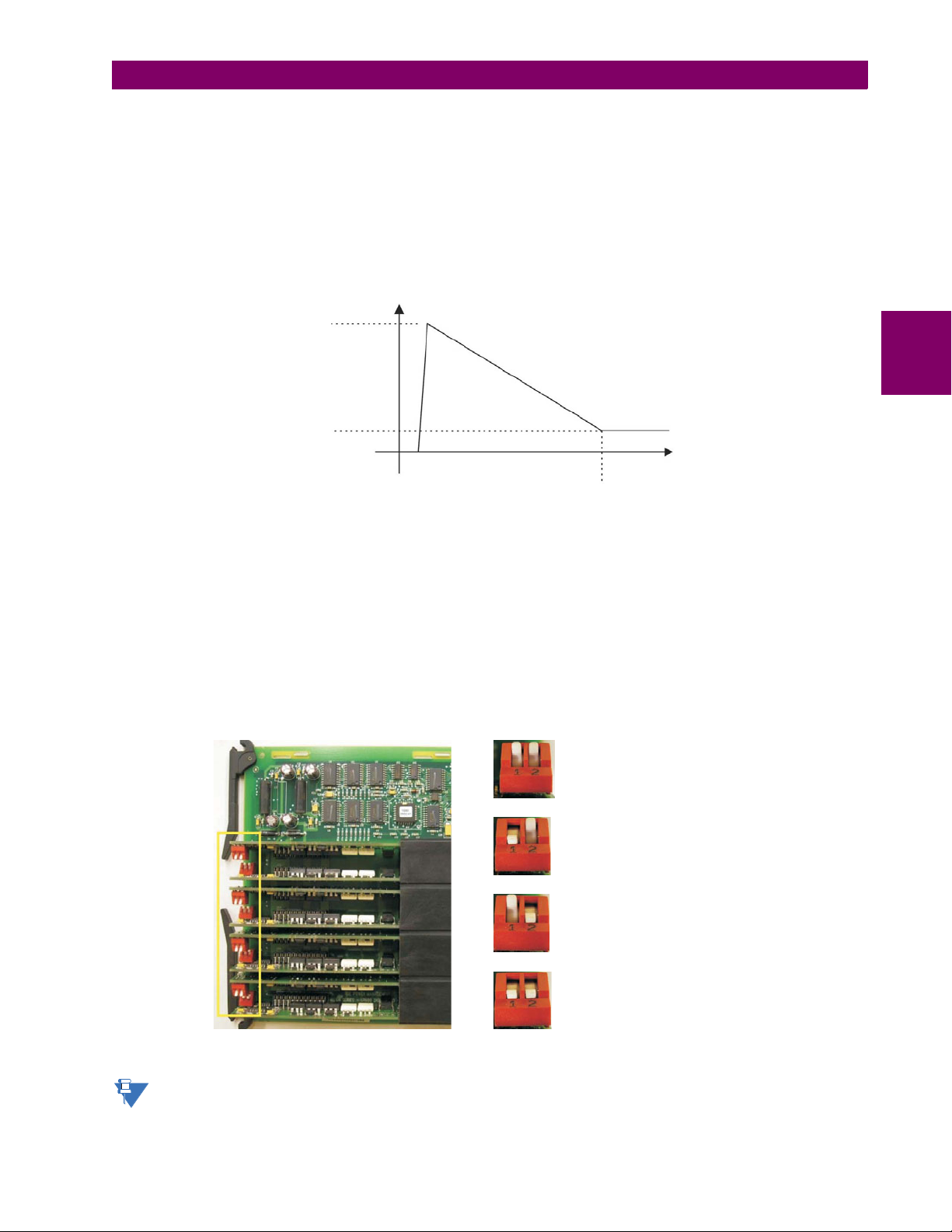
3 HARDWARE 3.2 WIRING
842749A1.CDR
50 to 70 mA
3 mA
25 to 50 ms
current
time
CONTACT INPUT 1 AUTO-BURNISH = OFF
= OFFCONTACT INPUT 2 AUTO-BURNISH
CONTACT INPUT 1 AUTO-BURNISH
CONTACT INPUT 2 AUTO-BURNISH
= ON
= OFF
CONTACT INPUT 1 AUTO-BURNISH
CONTACT INPUT 2 AUTO-BURNISH
= OFF
= ON
CONTACT INPUT 1 AUTO-BURNISH
CONTACT INPUT 2 AUTO-BURNISH
= ON
= ON
842751A1.CDR
USE OF CONTACT INPUTS WITH AUTO-BURNISHING
The contact inputs sense a change of the state of the external device contact based on the measured current. When external devices are located in a harsh industrial environment (either outdoor or indoor), their contacts can be exposed to various types of contamination. Normally, there is a thin film of insulating sulfidation, oxidation, or contaminates on the surface
of the contacts, sometimes making it difficult or impossible to detect a change of the state. This film must be removed to
establish circuit continuity – an impulse of higher than normal current can accomplish this.
The contact inputs with auto-burnish create a high current impulse when the threshold is reached to burn off this oxidation
layer as a maintenance to the contacts. Afterwards the contact input current is reduced to a steady-state current. The
impulse will have a 5 second delay after a contact input changes state.
Figure 3–20: CURRENT THROUGH CONTACT INPUTS WITH AUTO-BURNISHING
Regular contact inputs limit current to less than 3 mA to reduce station battery burden. In contrast, contact inputs with autoburnishing allow currents up to 50 to 70 mA at the first instance when the change of state was sensed. Then, within 25 to
50 ms, this current is slowly reduced to 3 mA as indicated above. The 50 to 70 mA peak current burns any film on the contacts, allowing for proper sensing of state changes. If the external device contact is bouncing, the auto-burnishing starts
when external device contact bouncing is over.
Another important difference between the auto-burnishing input module and the regular input modules is that only two contact inputs have common ground, as opposed to four contact inputs sharing one common ground (refer to the Contact Input
and Output Module Wiring diagrams). This is beneficial when connecting contact inputs to separate voltage sources. Consequently, the threshold voltage setting is also defined per group of two contact inputs.
The auto-burnish feature can be disabled or enabled using the DIP switches found on each daughter card. There is a DIP
switch for each contact, for a total of 16 inputs.
3
Figure 3–21: AUTO-BURNISH DIP SWITCHES
The auto-burnish circuitry has an internal fuse for safety purposes. During regular maintenance, the auto-burnish
functionality can be checked using an oscilloscope.
GE Multilin B30 Bus Differential System 3-21
Page 74

3.2 WIRING 3 HARDWARE
NOTE
842764A1.CDR
3.2.7 TRANSDUCER INPUTS AND OUTPUTS
Transducer input modules can receive input signals from external DCmA output transducers (DCmA In) or resistance temperature detectors (RTDs). Hardware and software are provided to receive signals from these external transducers and
convert these signals into a digital format for use as required.
Transducer output modules provide DC current outputs in several standard DCmA ranges. Software is provided to configure virtually any analog quantity used in the relay to drive the analog outputs.
Every transducer input/output module has a total of 24 terminal connections. These connections are arranged as three terminals per row with a total of eight rows. A given row may be used for either inputs or outputs, with terminals in column "a"
having positive polarity and terminals in column "c" having negative polarity. Since an entire row is used for a single input/
output channel, the name of the channel is assigned using the module slot position and row number.
Each module also requires that a connection from an external ground bus be made to terminal 8b. The current outputs
require a twisted-pair shielded cable, where the shield is grounded at one end only. The following figure illustrates the trans-
3
ducer module types (5A, 5C, 5D, 5E, and 5F) and channel arrangements that may be ordered for the relay.
Wherever a tilde “~” symbol appears, substitute with the slot position of the module.
Figure 3–22: TRANSDUCER INPUT/OUTPUT MODULE WIRING
The following figure show how to connect RTDs.
3-22 B30 Bus Differential System GE Multilin
Page 75

3 HARDWARE 3.2 WIRING
Three-wire shielded cable
RTD terminals
Maximum total lead resistance:
25 ohms for Platinum RTDs
Route cable in separate conduit from
current carrying conductors
RTD
859736A1.CDR
RTD terminals
RTD
RTD
For RTD
RTD
SURGE
~1
~1 &
~2
~2
~8b
~1a
~1b
~2a
Hot
Hot
Return
Comp
Comp
~2c
~1c
3
Figure 3–23: RTD CONNECTIONS
GE Multilin B30 Bus Differential System 3-23
Page 76

3.2 WIRING 3 HARDWARE
NOTE
NOTE
3.2.8 RS232 FACEPLATE PORT
A 9-pin RS232C serial port is located on the B30 faceplate for programming with a personal computer. All that is required to
use this interface is a personal computer running the EnerVista UR Setup software provided with the relay. Cabling for the
RS232 port is shown in the following figure for both 9-pin and 25-pin connectors.
The baud rate for this port is fixed at 19200 bps.
3
Figure 3–24: RS232 FACEPLATE PORT CONNECTION
3.2.9 CPU COMMUNICATION PORTS
a) OVERVIEW
In addition to the faceplate RS232 port, the B30 provides two additional communication ports or a managed six-port Ethernet switch, depending on the installed CPU module. In the following table, multiple Ethernet ports are supported, but only
one can be used at a time. For example, the 10Base-F (normal) port and 10Base-T (alternate) port are supported in the 9G
module, but only one can be used at a time.
The CPU modules do not require a surge ground connection.
Table 3–3: CPU MODULE COMMUNICATIONS (MODULE APPLICABLE DEPENDS ON ORDER CODE)
CPU TYPE COM1 COM2
9E RS485 RS485
9G 10Base-F or 10Base-T (obsolete) RS485
9H Redundant 10Base-F or 10Base-T (obsolete) RS485
9J 100Base-FX or 10/100Base-T RS485
9K Redundant 100Base-FX or 10/100Base-T RS485
9L 100Base-FX (obsolete) RS485
9M Redundant 100Base-FX (obsolete) RS485
9N 10/100Base-T RS485
9S Six-port managed Ethernet switch RS485
3-24 B30 Bus Differential System GE Multilin
Page 77

3 HARDWARE 3.2 WIRING
NOTE
100Base-FL
COMMON
+
+
—
—
D1a
D2a
D3a
D4b
D4a
BNC
BNC
IRIG-B output
IRIG-B
input
CPU
RS485
COM2
9L
COM1NORMAL
Co-axial cable
Co-axial cable
SM fiber
optic cable
Ground at
remote
device
NORMAL
ALTERNATE
COM1
100Base-FL
100Base-F
COMMON
+
+
—
—
D1a
D2a
D3a
D4b
D4a
BNC
BNC
IRIG-B output
IRIG-B
input
CPU 9M
Co-axial cable
Co-axial cable
Shielded twisted-pairs
SM fiber optic cable
Ground at
remote
device
RS485
COM2
COMMON
+
+
—
—
D1a
D2a
D3a
D4b
D4a
BNC
BNC
IRIG-B output
IRIG-B
input
CPU 9E
RS485
COM2
COMMON
+
—
D1b
D2b
D3b
RS485
COM1
Ground at
remote
device
Co-axial cable
Co-axial cable
Shielded twisted-pairs
842765A7b.CDR
CPU 9S
COMMON
+
+
—
—
D1a
D2a
D3a
D4b
D4a
BNC
BNC
IRIG-B output
IRIG-B
input
Co-axial cable
Co-axial cable
Shielded twisted-pairs
Ground at
remote
device
RS485
COM2
Ground at
remote
device
NORMAL
10/100Base-T
COMMON
+
+
—
—
D1a
D2a
D3a
D4b
D4a
BNC
BNC
IRIG-B output
IRIG-B
input
CPU
Co-axial cable
Co-axial cable
Shielded
twisted-pairs
RS485
COM2
COM1
9N
NORMAL
ALTERNATE
COM1
10Base-FL
10Base-FL
10Base-T
Tx1
Rx1
Tx2
Rx2
COMMON
+
+
—
—
D1a
D2a
D3a
D4b
D4a
BNC
BNC
IRIG-B output
IRIG-B
input
CPU 9H
Co-axial cable
Co-axial cable
Shielded
twisted-pairs
MM fiber
optic cable
Ground at
remote
device
RS485
COM2
REDUNDANT
NORMAL
ALTERNATE
COM1
100Base-FX
100Base-FX
10/100Base-T
Tx1
Rx1
Tx2
Rx2
COMMON
+
+
—
—
D1a
D2a
D3a
D4b
D4a
BNC
BNC
IRIG-B output
IRIG-B
input
CPU 9K
Co-axial cable
Co-axial cable
Shielded
twisted-pairs
MM fiber
optic cable
Ground at
remote
device
RS485
COM2
REDUNDANT
NORMAL
COM1
10Base-FL
10Base-T
Tx1
Rx1
COMMON
+
+
—
—
D1a
D2a
D3a
D4b
D4a
BNC
BNC
IRIG-B output
IRIG-B
input
CPU 9G
RS485
COM2
Shielded twisted-pairs
Co-axial cable
Co-axial cable
MM fiber
optic cable
Ground at
remote
device
ALTERNATE
100Base-FX
Tx1
Rx1
COMMON
+
+
—
—
D1a
D2a
D3a
D4b
D4a
BNC
BNC
IRIG-B output
IRIG-B
input
CPU
RS485
COM2
9J
COM1NORMAL
Co-axial cable
Co-axial cable
MM fiber
optic cable
Ground at
remote
device
10/100Base-T
ALTERNATE
For the 9G/9H CPU, the 10Base-T port can only be used when the CH1 10Base-F fiber has been removed. The
10Base-T Ethernet cable and the CH1 10Base-F fiber cable cannot both be installed at the same time.
For 9J/9K CPU, the 10/100Base-T port has the lowest priority and is only active if both CH1 and CH2 fiber links are
down. Installation of the 10/100Base-T Ethernet cable at the same time as the CH1 and/or CH2 100Base-F fiber
cables does not affect the communication over the CH1 or CH2 fiber ports.
3
Figure 3–25: CPU MODULE COMMUNICATIONS WIRING (MODULE APPLICABLE DEPENDS ON ORDER CODE)
GE Multilin B30 Bus Differential System 3-25
Page 78

3.2 WIRING 3 HARDWARE
SCADA / PLC / computer
Optocoupler
Data
UR-series device
Shield
827757AA.CDR
Last device
Z (*)
T
Z (*)
T
each end (typically 120 Ω and 1 nF)
Terminating impedance at
Twisted pair
RS485 +
RS485 –
COMP 485COM
Relay
Relay
Ground shield at SCADA / PLC /
computer only or at
UR-series device only
Data
Optocoupler
Up to 32 devices,
maximum 4000 feet
(1200 m)
Z (*)
T
RS485 +
RS485 –
COMP 485COM
RS485 +
RS485 –
COMP 485COM
COM
b) RS485 PORTS
RS485 data transmission and reception are accomplished over a single twisted pair with transmit and receive data alternating over the same two wires. Through the use of these ports, continuous monitoring and control from a remote computer,
SCADA system or PLC is possible.
To minimize errors from noise, the use of shielded twisted pair wire is recommended. Correct polarity must also be
observed. For instance, the relays must be connected with all RS485 “+” terminals connected together, and all RS485 “–”
terminals connected together. Though data is transmitted over a two-wire twisted pair, all RS485 devices require a shared
reference, or common voltage. This common voltage is implied to be a power supply common. Some systems allow the
shield (drain wire) to be used as common wire and to connect directly to the B30 COM terminal (#3); others function correctly only if the common wire is connected to the B30 COM terminal, but insulated from the shield.
To avoid loop currents, the shield should be grounded at only one point. If other system considerations require the shield to
be grounded at more than one point, install resistors (typically 100 ohms) between the shield and ground at each grounding
point. Each relay should also be daisy-chained to the next one in the link. A maximum of 32 relays can be connected in this
3
manner without exceeding driver capability. For larger systems, additional serial channels must be added. It is also possible
to use commercially available repeaters to have more than 32 relays on a single channel. Star or stub connections should
be avoided entirely.
Lightning strikes and ground surge currents can cause large momentary voltage differences between remote ends of the
communication link. For this reason, surge protection devices are internally provided at both communication ports. An isolated power supply with an optocoupled data interface also acts to reduce noise coupling. To ensure maximum reliability, all
equipment should have similar transient protection devices installed.
Both ends of the RS485 circuit should also be terminated with an impedance as shown below.
3-26 B30 Bus Differential System GE Multilin
Figure 3–26: RS485 SERIAL CONNECTION
Page 79

3 HARDWARE 3.2 WIRING
NOTICE
UR-series device
BNC (in)
Receiver
RG58/59 coaxial cable
GPS satellite system
GPS connection
IRIG-B (–)
4A
+
859716A1.CDR
IRIG-B
time code generator
(DC-shift or
amplitude modulated
signal can be used)
4B
IRIG-B (+)
BNC (out)
Repeater
To other devices
(DC-shift only)
UR-series device
BNC (in)
Receiver
Twisted-pair cable
GPS satellite system
GPS connection
IRIG-B (–)
4A
+
IRIG-B
time code generator
(DC-shift or
amplitude modulated
signal can be used)
4B
IRIG-B (+)
BNC (out)
Repeater
To other devices
(DC-shift only)
c) 10BASE-FL AND 100BASE-FX FIBER OPTIC PORTS
ENSURE THE DUST COVERS ARE INSTALLED WHEN THE FIBER IS NOT IN USE. DIRTY OR
SCRATCHED CONNECTORS CAN LEAD TO HIGH LOSSES ON A FIBER LINK.
The fiber optic communication ports allow for fast and efficient communications between relays at 10 Mbps or 100 Mbps.
Optical fiber may be connected to the relay supporting a wavelength of 820 nm in multi-mode or 1310 nm in multi-mode
and single-mode. The 10 Mbps rate is available for CPU modules 9G and 9H; 100Mbps is available for modules 9J, 9K, 9L,
9M, and 9N. The 9H, 9K, and 9M modules have a second pair of identical optical fiber transmitter and receiver for redundancy.
The optical fiber sizes supported include 50/125 µm, 62.5/125 µm and 100/140 µm for 10 Mbps. In order to engage or disengage the ST type connector, only a quarter turn of the coupling is required.
3.2.10 IRIG-B
IRIG-B is a standard time code format that allows stamping of events to be synchronized among connected devices. The
IRIG-B code allows time accuracies of up to 100 ns. Using the IRIG-B input, the B30 operates an internal oscillator with 1
µs resolution and accuracy. The IRIG time code formats are serial, width-modulated codes that can be either DC level
shifted or amplitude modulated (AM). Third party equipment is available for generating the IRIG-B signal; this equipment
can use a GPS satellite system to obtain the time reference so that devices at different geographic locations can be synchronized.
3
Figure 3–27: OPTIONS FOR IRIG-B CONNECTION
GE Multilin B30 Bus Differential System 3-27
Page 80

3.2 WIRING 3 HARDWARE
NOTE
The IRIG-B repeater provides an amplified DC-shift IRIG-B signal to other equipment. By using one IRIG-B serial connection, several UR-series relays can be synchronized. The IRIG-B repeater has a bypass function to maintain the time signal
even when a relay in the series is powered down.
3
Figure 3–28: IRIG-B REPEATER
Using an amplitude modulated receiver causes errors up to 1 ms in event time-stamping.
3-28 B30 Bus Differential System GE Multilin
Page 81

3 HARDWARE 3.3 DIRECT INPUT AND OUTPUT COMMUNICATIONS
842006A1.CDR
Tx
Tx
Tx
Tx
UR #1
UR #2
UR #3
UR #4
Rx
Rx
Rx
Rx
842007A1.CDR
Tx1
UR #1
UR #2
UR #3
UR #4
Tx1
Tx1
Tx1
Tx2
Tx2
Tx2
Tx2
Rx1
Rx1
Rx1
Rx1
Rx2
Rx2
Rx2
Rx2
3.3DIRECT INPUT AND OUTPUT COMMUNICATIONS 3.3.1 DESCRIPTION
The B30 direct inputs and outputs feature makes use of the type 7 series of communications modules. These modules are
also used by the L90 Line Differential Relay for inter-relay communications. The direct input and output feature uses the
communications channels provided by these modules to exchange digital state information between relays. This feature is
available on all UR-series relay models except for the L90 Line Differential relay.
The communications channels are normally connected in a ring configuration as shown below. The transmitter of one module is connected to the receiver of the next module. The transmitter of this second module is then connected to the receiver
of the next module in the ring. This is continued to form a communications ring. The figure below illustrates a ring of four
UR-series relays with the following connections: UR1-Tx to UR2-Rx, UR2-Tx to UR3-Rx, UR3-Tx to UR4-Rx, and UR4-Tx
to UR1-Rx. A maximum of 16 UR-series relays can be connected in a single ring
3
Figure 3–29: DIRECT INPUT AND OUTPUT SINGLE CHANNEL CONNECTION
The interconnection for dual-channel Type 7 communications modules is shown below. Two channel modules allow for a
redundant ring configuration. That is, two rings can be created to provide an additional independent data path. The required
connections are: UR1-Tx1 to UR2-Rx1, UR2-Tx1 to UR3-Rx1, UR3-Tx1 to UR4-Rx1, and UR4-Tx1 to UR1-Rx1 for the first
ring; and UR1-Tx2 to UR4-Rx2, UR4-Tx2 to UR3-Rx2, UR3-Tx2 to UR2-Rx2, and UR2-Tx2 to UR1-Rx2 for the second
ring.
The following diagram shows the connection for three UR-series relays using two independent communication channels.
UR1 and UR3 have single type 7 communication modules; UR2 has a dual-channel module. The two communication channels can be of different types, depending on the Type 7 modules used. To allow the direct input and output data to cross-
over from channel 1 to channel 2 on UR2, the
forces UR2 to forward messages received on Rx1 out Tx2, and messages received on Rx2 out Tx1.
GE Multilin B30 Bus Differential System 3-29
Figure 3–30: DIRECT INPUT AND OUTPUT DUAL CHANNEL CONNECTION
DIRECT I/O CHANNEL CROSSOVER setting should be “Enabled” on UR2. This
Page 82

842013A1.CDR
Tx
Tx
UR #1
Channel #1
Channel #2
UR #2
UR #3
Rx
Rx
Tx1
Tx2
Rx1
Rx2
NOTE
3.3 DIRECT INPUT AND OUTPUT COMMUNICATIONS 3 HARDWARE
3
Figure 3–31: DIRECT INPUT AND OUTPUT SINGLE/DUAL CHANNEL COMBINATION CONNECTION
The interconnection requirements are described in further detail in this section for each specific variation of type 7 communications module. These modules are listed in the following table. All fiber modules use ST type connectors.
Not all the direct input and output communications modules may be applicable to the B30 relay. Only the modules
specified in the order codes are available as direct input and output communications modules.
Table 3–4: CHANNEL COMMUNICATION OPTIONS (Sheet 1 of 2)
MODULE SPECIFICATION
2A C37.94SM, 1300 nm, single-mode, ELED, 1 channel single-mode
2B C37.94SM, 1300 nm, single-mode, ELED, 2 channel single-mode
2E Bi-phase, 1 channel
2F Bi-phase, 2 channel
2G IEEE C37.94, 820 nm, 128 kbps, multi-mode, LED, 1 channel
2H IEEE C37.94, 820 nm, 128 kbps, multi-mode, LED, 2 channels
2S Six-port managed Ethernet switch with high voltage power supply
2T Six-port managed Ethernet switch with low voltage power supply
72 1550 nm, single-mode, laser, 1 channel
73 1550 nm, single-mode, laser, 2 channels
74 Channel 1 - RS422; channel 2 - 1550 nm, single-mode, laser
75 Channel 1 - G.703; channel 2 - 1550 nm, single-mode, laser
76 IEEE C37.94, 820 nm, 64 kbps, multi-mode, LED, 1 channel
77 IEEE C37.94, 820 nm, 64 kbps, multi-mode, LED, 2 channels
7A 820 nm, multi-mode, LED, 1 channel
7B 1300 nm, multi-mode, LED, 1 channel
7C 1300 nm, single-mode, ELED, 1 channel
7D 1300 nm, single-mode, laser, 1 channel
7E Channel 1: G.703, Channel 2: 820 nm, multi-mode
7F Channel 1: G.703, Channel 2: 1300 nm, multi-mode
7G Channel 1: G.703, Channel 2: 1300 nm, single-mode ELED
7H 820 nm, multi-mode, LED, 2 channels
7I 1300 nm, multi-mode, LED, 2 channels
7J 1300 nm, single-mode, ELED, 2 channels
7K 1300 nm, single-mode, LASER, 2 channels
7L Channel 1: RS422, channel: 820 nm, multi-mode, LED
7M Channel 1: RS422, channel 2: 1300 nm, multi-mode, LED
3-30 B30 Bus Differential System GE Multilin
Page 83

3 HARDWARE 3.3 DIRECT INPUT AND OUTPUT COMMUNICATIONS
CAUTION
Module: 7A / 7B / 7C 7H / 7I / 7J
Connection Location: Slot X Slot X
1 Channel 2 Channels
RX1 RX1
RX2
TX1 TX1
TX2
831719A2.CDR
Module:
Connection Location:
73/ 7K
Slot X
72/ 7D
Slot X
1 Channel 2 Channels
RX1 RX1
RX2
TX1 TX1
TX2
831720A3.CDR
Table 3–4: CHANNEL COMMUNICATION OPTIONS (Sheet 2 of 2)
MODULE SPECIFICATION
7N Channel 1: RS422, channel 2: 1300 nm, single-mode, ELED
7P Channel 1: RS422, channel 2: 1300 nm, single-mode, laser
7Q Channel 1: G.703, channel 2: 1300 nm, single-mode, laser
7R G.703, 1 channel
7S G.703, 2 channels
7T RS422, 1 channel
7V RS422, 2 channels, 2 clock inputs
7W RS422, 2 channels
OBSERVING ANY FIBER TRANSMITTER OUTPUT MAY CAUSE INJURY TO THE EYE.
3.3.2 FIBER: LED AND ELED TRANSMITTERS
The following figure shows the configuration for the 7A, 7B, 7C, 7H, 7I, and 7J fiber-only modules.
3
The following figure shows the configuration for the 72, 73, 7D, and 7K fiber-laser module.
GE Multilin B30 Bus Differential System 3-31
Figure 3–32: LED AND ELED FIBER MODULES
3.3.3 FIBER-LASER TRANSMITTERS
Figure 3–33: LASER FIBER MODULES
Page 84

3.3 DIRECT INPUT AND OUTPUT COMMUNICATIONS 3 HARDWARE
CAUTION
NOTICE
NOTE
842773A2.CDR
X
X
X
X
X
X
X
X
X
X
X
X
8a
8b
7S
Rx +
Tx +
Shield
Tx –
Shield
Rx –
Tx –
Rx +
Tx +
Rx –
Inter-relay communications
2b
6a
7a
1b
1a
3a
6b
7b
2a
3b
G.703
channel 2
G.703
channel 1
Surge
Surge
831727A3.CDR
X
X
X
X
X
X
X
X
X
X
X
X
8a
8b
7S
Rx +
Tx +
Shld.
Tx -
Shld.
Rx -
Tx -
Rx +
Tx +
Rx -
COMM.
2b
6a
7a
1b
1a
3a
6b
7b
2a
3b
G.703
CHANNEL 2
G.703
CHANNEL 1
SURGE
SURGE
X
X
X
X
X
X
X
X
X
X
X
X
8a
8b
7S
Rx +
Tx +
Shld.
Tx -
Shld.
Rx -
Tx -
Rx +
Tx +
Rx -
COMM.
2b
6a
7a
1b
1a
3a
6b
7b
2a
3b
G.703
CHANNEL 2
G.703
CHANNEL 1
SURGE
SURGE
NOTE
Observing any fiber transmitter output can injure the eye.
When using a laser Interface, attenuators may be necessary to ensure that you do not exceed the
maximum optical input power to the receiver.
3.3.4 G.703 INTERFACE
a) DESCRIPTION
The following figure shows the 64K ITU G.703 co-directional interface configuration.
The G.703 module is fixed at 64 kbps. The
SETTINGS PRODUCT SETUP DIRECT I/O DIRECT I/O DATA RATE
setting is not applicable to this module.
3
AWG 24 twisted shielded pair is recommended for external connections, with the shield grounded only at one end. Connecting the shield to pin X1a or X6a grounds the shield since these pins are internally connected to ground. Thus, if pin X1a
or X6a is used to ground the shield at one end, do not ground the shield at the other end. This interface module is protected
by surge suppression devices.
Figure 3–34: G.703 INTERFACE CONFIGURATION
The following figure shows the typical pin interconnection between two G.703 interfaces. For the actual physical arrangement of these pins, see the Rear terminal assignments section earlier in this chapter. All pin interconnections are to be
maintained for a connection to a multiplexer.
Figure 3–35: TYPICAL PIN INTERCONNECTION BETWEEN TWO G.703 INTERFACES
Pin nomenclature may differ from one manufacturer to another. Therefore, it is not uncommon to see pinouts numbered TxA, TxB, RxA and RxB. In such cases, it can be assumed that “A” is equivalent to “+” and
“B” is equivalent to “–”.
b) G.703 SELECTION SWITCH PROCEDURES
1. Remove the G.703 module (7R or 7S). The ejector/inserter clips located at the top and at the bottom of each module,
3-32 B30 Bus Differential System GE Multilin
must be pulled simultaneously in order to release the module for removal. Before performing this action, control
power must be removed from the relay. The original location of the module should be recorded to help ensure that
the same or replacement module is inserted into the correct slot.
Page 85

3 HARDWARE 3.3 DIRECT INPUT AND OUTPUT COMMUNICATIONS
2. Remove the module cover screw.
3. Remove the top cover by sliding it towards the rear and then lift it upwards.
4. Set the timing selection switches (channel 1, channel 2) to the desired timing modes.
5. Replace the top cover and the cover screw.
6. Re-insert the G.703 module. Take care to ensure that the correct module type is inserted into the correct slot position.
The ejector/inserter clips located at the top and at the bottom of each module must be in the disengaged position as
the module is smoothly inserted into the slot. Once the clips have cleared the raised edge of the chassis, engage the
clips simultaneously. When the clips have locked into position, the module will be fully inserted.
3
Figure 3–36: G.703 TIMING SELECTION SWITCH SETTING
Table 3–5: G.703 TIMING SELECTIONS
SWITCHES FUNCTION
S1 OFF → octet timing disabled
S5 and S6 S5 = OFF and S6 = OFF → loop timing mode
c) G.703 OCTET TIMING
If octet timing is enabled (on), this 8 kHz signal will be asserted during the violation of bit 8 (LSB) necessary for connecting
to higher order systems. When B30s are connected back to back, octet timing should be disabled (off).
d) G.703 TIMING MODES
There are two timing modes for the G.703 module: internal timing mode and loop timing mode (default).
• Internal Timing Mode: The system clock is generated internally. Therefore, the G.703 timing selection should be in
the internal timing mode for back-to-back (UR-to-UR) connections. For back-to-back connections, set for octet timing
(S1 = OFF) and timing mode to internal timing (S5 = ON and S6 = OFF).
GE Multilin B30 Bus Differential System 3-33
ON → octet timing 8 kHz
S5 = ON and S6 = OFF → internal timing mode
S5 = OFF and S6 = ON → minimum remote loopback mode
S5 = ON and S6 = ON → dual loopback mode
Page 86

3.3 DIRECT INPUT AND OUTPUT COMMUNICATIONS 3 HARDWARE
842752A1.CDR
DMR
DMX
G7X
G7R
DMR = Differential Manchester Receiver
DMX = Differential Manchester Transmitter
G7X = G.703 Transmitter
G7R = G.703 Receiver
842774A1.CDR
DMR
DMX
G7X
G7R
DMR = Differential Manchester Receiver
DMX = Differential Manchester Transmitter
G7X = G.703 Transmitter
G7R = G.703 Receiver
842775A1.CDR
• Loop Timing Mode: The system clock is derived from the received line signal. Therefore, the G.703 timing selection
should be in loop timing mode for connections to higher order systems. For connection to a higher order system (URto-multiplexer, factory defaults), set to octet timing (S1 = ON) and set timing mode to loop timing (S5 = OFF and S6 =
OFF).
The switch settings for the internal and loop timing modes are shown below:
3
e) G.703 TEST MODES
In minimum remote loopback mode, the multiplexer is enabled to return the data from the external interface without any
processing to assist in diagnosing G.703 line-side problems irrespective of clock rate. Data enters from the G.703 inputs,
passes through the data stabilization latch which also restores the proper signal polarity, passes through the multiplexer
and then returns to the transmitter. The differential received data is processed and passed to the G.703 transmitter module
after which point the data is discarded. The G.703 receiver module is fully functional and continues to process data and
passes it to the differential Manchester transmitter module. Since timing is returned as it is received, the timing source is
expected to be from the G.703 line side of the interface.
Figure 3–37: G.703 MINIMUM REMOTE LOOPBACK MODE
In dual loopback mode, the multiplexers are active and the functions of the circuit are divided into two with each receiver/
transmitter pair linked together to deconstruct and then reconstruct their respective signals. Differential Manchester data
enters the Differential Manchester receiver module and then is returned to the differential Manchester transmitter module.
Likewise, G.703 data enters the G.703 receiver module and is passed through to the G.703 transmitter module to be
returned as G.703 data. Because of the complete split in the communications path and because, in each case, the clocks
are extracted and reconstructed with the outgoing data, in this mode there must be two independent sources of timing. One
source lies on the G.703 line side of the interface while the other lies on the differential Manchester side of the interface.
Figure 3–38: G.703 DUAL LOOPBACK MODE
3-34 B30 Bus Differential System GE Multilin
Page 87

3 HARDWARE 3.3 DIRECT INPUT AND OUTPUT COMMUNICATIONS
~
~
~
~
~
~
~
~
~
~
~
~
~
~
Shield
Shield
COM
Tx +
Tx +
Tx –
Tx –
Rx –
Rx –
Rx +
Rx +
3b
5b
2a
4a
6a
7b
8b
Clock
RS422
channel 1
RS422
channel 2
Surge
3a
5a
4b
6b
7a
2b
8a
Inter-relay communications 7W
842776A3.CDR
Dual-channel RS422 module
~
~
~
~
~
Shield
Tx +
Tx –
Rx –
Rx +
3b
2a
6a
RS422
3a
4b
~
~
~
~
COM
8b
Clock
Surge
7a
2b
8a
Inter-relay comms. 7T
Single-channel RS422 module
~ indicates the slot position
3.3.5 RS422 INTERFACE
a) DESCRIPTION
There are two RS422 inter-relay communications modules available: single-channel RS422 (module 7T) and dual-channel
RS422 (module 7W). The modules can be configured to run at 64 kbps or 128 kbps. AWG 24 twisted shielded pair cable is
recommended for external connections. These modules are protected by optically-isolated surge suppression devices.
The shield pins (6a and 7b) are internally connected to the ground pin (8a). Proper shield termination is as follows:
• Site 1: Terminate shield to pins 6a or 7b or both.
• Site 2: Terminate shield to COM pin 2b.
The clock terminating impedance should match the impedance of the line.
3
The following figure shows the typical pin interconnection between two single-channel RS422 interfaces installed in slot W.
All pin interconnections are to be maintained for a connection to a multiplexer.
b) TWO-CHANNEL APPLICATION VIA MULTIPLEXERS
The RS422 interface may be used for single channel or two channel applications over SONET/SDH or multiplexed systems. When used in single-channel applications, the RS422 interface links to higher order systems in a typical fashion
observing transmit (Tx), receive (Rx), and send timing (ST) connections. However, when used in two-channel applications,
certain criteria must be followed since there is one clock input for the two RS422 channels. The system will function correctly if the following connections are observed and your data module has a terminal timing feature. Terminal timing is a
common feature to most synchronous data units that allows the module to accept timing from an external source. Using the
terminal timing feature, two channel applications can be achieved if these connections are followed: The send timing outputs from the multiplexer (data module 1), will connect to the clock inputs of the UR–RS422 interface in the usual fashion.
In addition, the send timing outputs of data module 1 will also be paralleled to the terminal timing inputs of data module 2.
By using this configuration, the timing for both data modules and both UR–RS422 channels will be derived from a single
clock source. As a result, data sampling for both of the UR–RS422 channels will be synchronized via the send timing leads
on data module 1 as shown below. If the terminal timing feature is not available or this type of connection is not desired, the
G.703 interface is a viable option that does not impose timing restrictions.
GE Multilin B30 Bus Differential System 3-35
Figure 3–39: RS422 INTERFACE CONNECTIONS
Figure 3–40: TYPICAL PIN INTERCONNECTION BETWEEN TWO RS422 INTERFACES
Page 88

3
Data module 1
Data module 2
Signal name
Signal name
SD(A) - Send data
TT(A) - Terminal timing
TT(B) - Terminal timing
SD(B) - Send data
RD(A) - Received data
RD(A) - Received data
SD(A) - Send data
SD(B) - Send data
RD(B) - Received data
RD(B) - Received data
RS(A) - Request to send (RTS)
RS(A) - Request to send (RTS)
RT(A) - Receive timing
CS(A) - Clear To send
CS(A) - Clear To send
RT(B) - Receive timing
CS(B) - Clear To send
CS(B) - Clear To send
Local loopback
Local loopback
Remote loopback
Remote loopback
Signal ground
Signal ground
ST(A) - Send timing
ST(A) - Send timing
ST(B) - Send timing
ST(B) - Send timing
RS(B) - Request to send (RTS)
RS(B) - Request to send (RTS)
831022A3.CDR
W
7a
W
2b
W
8a
7W
Shld.
Shld.
Tx1(+)
Tx2(+)
Tx1(-)
Tx2(-)
Rx1(+)
Rx2(+)
+
com
Rx1(-)
Rx2(-)
–
INTER-RELAY COMMUNICATIONS
W
3a
W
5b
W
5a
W
3b
W
2a
W
6a
W
6b
W
7b
W
8b
W
4b
W
4a
RS422
CHANNEL 1
RS422
CHANNEL 2
CLOCK
SURGE
Tx Clock
Tx Data
3.3 DIRECT INPUT AND OUTPUT COMMUNICATIONS 3 HARDWARE
Figure 3–41: TIMING CONFIGURATION FOR RS422 TWO-CHANNEL, 3-TERMINAL APPLICATION
Data module 1 provides timing to the B30 RS422 interface via the ST(A) and ST(B) outputs. Data module 1 also provides
timing to data module 2 TT(A) and TT(B) inputs via the ST(A) and AT(B) outputs. The data module pin numbers have been
omitted in the figure above since they may vary depending on the manufacturer.
c) TRANSMIT TIMING
The RS422 interface accepts one clock input for transmit timing. It is important that the rising edge of the 64 kHz transmit
timing clock of the multiplexer interface is sampling the data in the center of the transmit data window. Therefore, it is important to confirm clock and data transitions to ensure proper system operation. For example, the following figure shows the
positive edge of the Tx clock in the center of the Tx data bit.
d) RECEIVE TIMING
The RS422 interface utilizes NRZI-MARK modulation code and; therefore, does not rely on an Rx clock to recapture data.
NRZI-MARK is an edge-type, invertible, self-clocking code.
3-36 B30 Bus Differential System GE Multilin
Figure 3–42: CLOCK AND DATA TRANSITIONS
Page 89

3 HARDWARE 3.3 DIRECT INPUT AND OUTPUT COMMUNICATIONS
NOTICE
~
~
~
~
~
~
~
~
~
Shield
COM
Tx1 +
Tx1 –
Rx1 –
Rx1 +
1a
2b
3a
4b
Fiber
channel 2
Clock
(channel 1)
RS422
channel 1
Surge
1b
2a
3b
6a
8a
Tx2
Rx2
Inter-relay comms. 7L, 7M, 7N, 7P, 74
842777A1.CDR
NOTICE
~
~
~
~
~
~
Shield
Tx –
Tx +
Rx –
Rx +
1a
2a
3a
Fiber
channel 2
G.703
channel 1
Surge
1b
2b
3b
Tx2
Rx2
Inter-relay
communications
7E, 7F, 7G,
7Q,75
842778A1.CDR
To recover the Rx clock from the data-stream, an integrated DPLL (digital phase lock loop) circuit is utilized. The DPLL is
driven by an internal clock, which is 16-times over-sampled, and uses this clock along with the data-stream to generate a
data clock that can be used as the SCC (serial communication controller) receive clock.
3.3.6 RS422 AND FIBER INTERFACE
The following figure shows the combined RS422 plus Fiber interface configuration at 64K baud. The 7L, 7M, 7N, 7P, and 74
modules are used in two-terminal with a redundant channel or three-terminal configurations where channel 1 is employed
via the RS422 interface (possibly with a multiplexer) and channel 2 via direct fiber.
AWG 24 twisted shielded pair is recommended for external RS422 connections and the shield should be grounded only at
one end. For the direct fiber channel, power budget issues should be addressed properly.
When using a laser interface, attenuators may be necessary to ensure that you do not exceed maximum optical input power to the receiver.
3
Figure 3–43: RS422 AND FIBER INTERFACE CONNECTION
Connections shown above are for multiplexers configured as DCE (data communications equipment) units.
3.3.7 G.703 AND FIBER INTERFACE
The figure below shows the combined G.703 plus fiber interface configuration at 64 kbps. The 7E, 7F, 7G, 7Q, and 75 modules are used in configurations where channel 1 is employed via the G.703 interface (possibly with a multiplexer) and channel 2 via direct fiber. AWG 24 twisted shielded pair is recommended for external G.703 connections connecting the shield to
pin 1a at one end only. For the direct fiber channel, power budget issues should be addressed properly. See previous sections for additional details on the G.703 and fiber interfaces.
When using a laser interface, attenuators may be necessary to ensure that you do not exceed the
maximum optical input power to the receiver.
GE Multilin B30 Bus Differential System 3-37
Figure 3–44: G.703 AND FIBER INTERFACE CONNECTION
Page 90

3.3 DIRECT INPUT AND OUTPUT COMMUNICATIONS 3 HARDWARE
3.3.8 IEEE C37.94 INTERFACE
The UR-series IEEE C37.94 communication modules (modules types 2G, 2H, 76, and 77) are designed to interface with
IEEE C37.94 compliant digital multiplexers or an IEEE C37.94 compliant interface converter for use with direct input and
output applications for firmware revisions 3.30 and higher. The IEEE C37.94 standard defines a point-to-point optical link
for synchronous data between a multiplexer and a teleprotection device. This data is typically 64 kbps, but the standard
provides for speeds up to 64n kbps, where n = 1, 2,…, 12. The UR-series C37.94 communication modules are either
64 kbps (with n fixed at 1) for 128 kbps (with n fixed at 2). The frame is a valid International Telecommunications Union
(ITU-T) recommended G.704 pattern from the standpoint of framing and data rate. The frame is 256 bits and is repeated at
a frame rate of 8000 Hz, with a resultant bit rate of 2048 kbps.
The specifications for the module are as follows:.
• IEEE standard: C37.94 for 1 × 128 kbps optical fiber interface (for 2G and 2H modules) or C37.94 for 2 × 64 kbps opti-
3
cal fiber interface (for 76 and 77 modules).
• Fiber optic cable type: 50 nm or 62.5 µm core diameter optical fiber.
• Fiber optic mode: multi-mode.
• Fiber optic cable length: up to 2 km.
• Fiber optic connector: type ST.
• Wavelength: 820 ±40 nm.
• Connection: as per all fiber optic connections, a Tx to Rx connection is required.
The UR-series C37.94 communication module can be connected directly to any compliant digital multiplexer that supports
the IEEE C37.94 standard as shown below.
The UR-series C37.94 communication module can be connected to the electrical interface (G.703, RS422, or X.21) of a
non-compliant digital multiplexer via an optical-to-electrical interface converter that supports the IEEE C37.94 standard, as
shown below.
In 2008, GE Digital Energy released revised modules 76 and 77 for C37.94 communication to enable multi-ended fault
location functionality with firmware 5.60 release and higher. All modules 76 and 77 shipped since the change support this
feature and are fully backward compatible with firmware releases below 5.60. For customers using firmware release 5.60
and higher, the module can be identified with "Rev D" printed on the module and is to be used on all ends of B30 communication for two and three terminal applications. Failure to use it at all ends results in intermittent communication alarms. For
customers using firmware revisions below 5.60, it is not required to match the revision of the modules installed.
3-38 B30 Bus Differential System GE Multilin
Page 91

3 HARDWARE 3.3 DIRECT INPUT AND OUTPUT COMMUNICATIONS
842753A1.CDR
The UR-series C37.94 communication module has six switches that are used to set the clock configuration. The functions
of these control switches is shown below.
For the internal timing mode, the system clock is generated internally. therefore, the timing switch selection should be internal timing for relay 1 and loop timed for relay 2. There must be only one timing source configured.
For the looped timing mode, the system clock is derived from the received line signal. Therefore, the timing selection
should be in loop timing mode for connections to higher order systems.
The IEEE C37.94 communications module cover removal procedure is as follows:
1. Remove the IEEE C37.94 module (type 2G, 2H, 76 or 77 module):
The ejector/inserter clips located at the top and at the bottom of each module, must be pulled simultaneously in order
to release the module for removal. Before performing this action, control power must be removed from the relay.
The original location of the module should be recorded to help ensure that the same or replacement module is inserted
into the correct slot.
2. Remove the module cover screw.
3. Remove the top cover by sliding it towards the rear and then lift it upwards.
4. Set the timing selection switches (channel 1, channel 2) to the desired timing modes (see description above).
5. Replace the top cover and the cover screw.
6. Re-insert the IEEE C37.94 module. Take care to ensure that the correct module type is inserted into the correct slot
position. The ejector/inserter clips located at the top and at the bottom of each module must be in the disengaged position as the module is smoothly inserted into the slot. Once the clips have cleared the raised edge of the chassis,
engage the clips simultaneously. When the clips have locked into position, the module will be fully inserted.
3
GE Multilin B30 Bus Differential System 3-39
Page 92

3
3.3 DIRECT INPUT AND OUTPUT COMMUNICATIONS 3 HARDWARE
Figure 3–45: IEEE C37.94 TIMING SELECTION SWITCH SETTING
3-40 B30 Bus Differential System GE Multilin
Page 93

3 HARDWARE 3.3 DIRECT INPUT AND OUTPUT COMMUNICATIONS
3.3.9 C37.94SM INTERFACE
The UR-series C37.94SM communication modules (2A and 2B) are designed to interface with modified IEEE C37.94 compliant digital multiplexers or IEEE C37.94 compliant interface converters that have been converted from 820 nm multi-mode
fiber optics to 1300 nm ELED single-mode fiber optics. The IEEE C37.94 standard defines a point-to-point optical link for
synchronous data between a multiplexer and a teleprotection device. This data is typically 64 kbps, but the standard provides for speeds up to 64n kbps, where n = 1, 2,…, 12. The UR-series C37.94SM communication module is 64 kbps only
with n fixed at 1. The frame is a valid International Telecommunications Union (ITU-T) recommended G.704 pattern from
the standpoint of framing and data rate. The frame is 256 bits and is repeated at a frame rate of 8000 Hz, with a resultant bit
rate of 2048 kbps.
The specifications for the module are as follows:
• Emulated IEEE standard: emulates C37.94 for 1 × 64 kbps optical fiber interface (modules set to n = 1 or 64 kbps).
• Fiber optic cable type: 9/125 μm core diameter optical fiber.
• Fiber optic mode: single-mode, ELED compatible with HP HFBR-1315T transmitter and HP HFBR-2316T receiver.
• Fiber optic cable length: up to 10 km.
• Fiber optic connector: type ST.
• Wavelength: 1300 ±40 nm.
• Connection: as per all fiber optic connections, a Tx to Rx connection is required.
The UR-series C37.94SM communication module can be connected directly to any compliant digital multiplexer that supports C37.94SM as shown below.
3
It can also can be connected directly to any other UR-series relay with a C37.94SM module as shown below.
In 2008, GE Digital Energy released revised modules 2A and 2B for C37.94SM communication to enable multi-ended fault
location functionality with firmware 5.60 release and higher. All modules 2A and 2B shipped since the change support this
feature and are fully backward compatible with firmware releases below 5.60. For customers using firmware release 5.60
and higher, the module can be identified with "Rev D" printed on the module and is to be used on all ends of B30 communication for two and three terminal applications. Failure to use it at all ends results in intermittent communication alarms. For
customers using firmware revisions below 5.60, it is not required to match the revision of the modules installed.
GE Multilin B30 Bus Differential System 3-41
Page 94

3.3 DIRECT INPUT AND OUTPUT COMMUNICATIONS 3 HARDWARE
842753A1.CDR
The UR-series C37.94SM communication module has six switches that are used to set the clock configuration. The functions of these control switches is shown below.
For the internal timing mode, the system clock is generated internally. Therefore, the timing switch selection should be
internal timing for relay 1 and loop timed for relay 2. There must be only one timing source configured.
3
For the looped timing mode, the system clock is derived from the received line signal. Therefore, the timing selection
should be in loop timing mode for connections to higher order systems.
The C37.94SM communications module cover removal procedure is as follows:
1. Remove the C37.94SM module (modules 2A or 2B):
The ejector/inserter clips located at the top and at the bottom of each module, must be pulled simultaneously in order
to release the module for removal. Before performing this action, control power must be removed from the relay.
The original location of the module should be recorded to help ensure that the same or replacement module is inserted
into the correct slot.
2. Remove the module cover screw.
3. Remove the top cover by sliding it towards the rear and then lift it upwards.
4. Set the timing selection switches (channel 1, channel 2) to the desired timing modes (see description above).
5. Replace the top cover and the cover screw.
6. Re-insert the C37.94SM module. Take care to ensure that the correct module type is inserted into the correct slot
position. The ejector/inserter clips located at the top and at the bottom of each module must be in the disengaged position as the module is smoothly inserted into the slot. Once the clips have cleared the raised edge of the chassis,
engage the clips simultaneously. When the clips have locked into position, the module will be fully inserted.
3-42 B30 Bus Differential System GE Multilin
Page 95

3 HARDWARE 3.3 DIRECT INPUT AND OUTPUT COMMUNICATIONS
3
Figure 3–46: C37.94SM TIMING SELECTION SWITCH SETTING
GE Multilin B30 Bus Differential System 3-43
Page 96

3
3.3 DIRECT INPUT AND OUTPUT COMMUNICATIONS 3 HARDWARE
3-44 B30 Bus Differential System GE Multilin
Page 97

4 HUMAN INTERFACES 4.1 ENERVISTA UR SETUP SOFTWARE INTERFACE
4 HUMAN INTERFACES 4.1ENERVISTA UR SETUP SOFTWARE INTERFACE 4.1.1 INTRODUCTION
The EnerVista UR Setup software provides a graphical user interface (GUI) as one of two human interfaces to a UR device.
The alternate human interface is implemented via the device’s faceplate keypad and display (refer to the Faceplate inter-
face section in this chapter).
The EnerVista UR Setup software provides a single facility to configure, monitor, maintain, and trouble-shoot the operation
of relay functions, connected over local or wide area communication networks. It can be used while disconnected (off-line)
or connected (on-line) to a UR device. In off-line mode, settings files can be created for eventual downloading to the device.
In on-line mode, you can communicate with the device in real-time.
The EnerVista UR Setup software, provided with every B30 relay, can be run from any computer supporting Microsoft
®
95, 98, NT, 2000, ME, and XP. This chapter provides a summary of the basic EnerVista UR Setup software interface
dows
features. The EnerVista UR Setup Help File provides details for getting started and using the EnerVista UR Setup software
interface.
4.1.2 CREATING A SITE LIST
To start using the EnerVista UR Setup software, a site definition and device definition must first be created. See the EnerVista UR Setup Help File or refer to the Connecting EnerVista UR Setup with the B30 section in Chapter 1 for details.
4.1.3 ENERVISTA UR SETUP OVERVIEW
a) ENGAGING A DEVICE
The EnerVista UR Setup software may be used in on-line mode (relay connected) to directly communicate with the B30
relay. Communicating relays are organized and grouped by communication interfaces and into sites. Sites may contain any
number of relays selected from the UR-series of relays.
Win-
4
b) USING SETTINGS FILES
The EnerVista UR Setup software interface supports three ways of handling changes to relay settings:
• In off-line mode (relay disconnected) to create or edit relay settings files for later download to communicating relays.
• While connected to a communicating relay to directly modify any relay settings via relay data view windows, and then
save the settings to the relay.
• You can create/edit settings files and then write them to the relay while the interface is connected to the relay.
Settings files are organized on the basis of file names assigned by the user. A settings file contains data pertaining to the
following types of relay settings:
• Device definition
• Product setup
• System setup
• FlexLogic™
• Grouped elements
• Control elements
• Inputs/outputs
• Testing
Factory default values are supplied and can be restored after any changes.
The following communications settings are not transferred to the B30 with settings files.
Modbus Slave Address
Modbus TCP Port Number
RS485 COM1 Baud Rate
RS485 COM1 Parity
COM1 Minimum Response Time
GE Multilin B30 Bus Differential System 4-1
Page 98

4.1 ENERVISTA UR SETUP SOFTWARE INTERFACE 4 HUMAN INTERFACES
RS485 COM2 Baud Rate
RS485 COM2 Parity
COM2 Minimum Response Time
COM2 Selection
RRTD Slave Address
RRTD Baud Rate
IP Address
IP Subnet Mask
Gateway IP Address
Ethernet Sub Module Serial Number
Network Address NSAP
IEC61850 Config GOOSE ConfRev
When a settings file is loaded to a B30 that is in-service, the following sequence occurs:
1. The B30 takes itself out of service.
2. The B30 issues a
3. The B30 closes the critical fail contact.
UNIT NOT PROGRAMMED major self-test error.
4
c) CREATING AND EDITING FLEXLOGIC™
You can create or edit a FlexLogic™ equation in order to customize the relay. You can subsequently view the automatically
generated logic diagram.
d) VIEWING ACTUAL VALUES
You can view real-time relay data such as input/output status and measured parameters.
e) VIEWING TRIGGERED EVENTS
While the interface is in either on-line or off-line mode, you can view and analyze data generated by triggered specified
parameters, via one of the following
• Event recorder
The event recorder captures contextual data associated with the last 1024 events, listed in chronological order from
most recent to oldest.
• Oscillography
The oscillography waveform traces and digital states are used to provide a visual display of power system and relay
operation data captured during specific triggered events.
f) FILE SUPPORT
• Execution: Any EnerVista UR Setup file which is double clicked or opened will launch the application, or provide focus
to the already opened application. If the file was a settings file (has a URS extension) which had been removed from
the Settings List tree menu, it will be added back to the Settings List tree menu.
• Drag and Drop: The Site List and Settings List control bar windows are each mutually a drag source and a drop target
for device-order-code-compatible files or individual menu items. Also, the Settings List control bar window and any
Windows Explorer directory folder are each mutually a file drag source and drop target.
New files which are dropped into the Settings List window are added to the tree which is automatically sorted alphabetically with respect to settings file names. Files or individual menu items which are dropped in the selected device menu
in the Site List window will automatically be sent to the on-line communicating device.
g) FIRMWARE UPGRADES
The firmware of a B30 device can be upgraded, locally or remotely, via the EnerVista UR Setup software. The corresponding instructions are provided by the EnerVista UR Setup Help file under the topic “Upgrading Firmware”.
4-2 B30 Bus Differential System GE Multilin
Page 99

4 HUMAN INTERFACES 4.1 ENERVISTA UR SETUP SOFTWARE INTERFACE
NOTE
Before backing up settings and upgrading, set the Settings > Product Setup > Security > Dual Permission Security
Access > Remote Setting Authorized and Local Setting Authorized settings to "ON." Otherwise, the upgrade is blocked
and results in an "Unable to put relay in flash mode" message.
Modbus addresses assigned to firmware modules, features, settings, and corresponding data items (i.e. default
values, minimum/maximum values, data type, and item size) may change slightly from version to version of firmware. The addresses are rearranged when new features are added or existing features are enhanced or modified.
EEPROM DATA ERROR message displayed after upgrading/downgrading the firmware is a resettable, self-test
The
message intended to inform users that the Modbus addresses have changed with the upgraded firmware. This
message does not signal any problems when appearing after firmware upgrades.
4.1.4 ENERVISTA UR SETUP MAIN WINDOW
The EnerVista UR Setup software main window supports the following primary display components:
1. Title bar which shows the pathname of the active data view.
2. Main window menu bar.
3. Main window tool bar.
4. Site list control bar window.
5. Settings list control bar window.
6. Device data view windows, with common tool bar.
7. Settings file data view windows, with common tool bar.
8. Workspace area with data view tabs.
9. Status bar.
10. Quick action hot links.
4
GE Multilin B30 Bus Differential System 4-3
Page 100

4
1
2
3
4
5
6
7
8
9
842786A2.CDR
10
4.1 ENERVISTA UR SETUP SOFTWARE INTERFACE 4 HUMAN INTERFACES
Figure 4–1: ENERVISTA UR SETUP SOFTWARE MAIN WINDOW
4-4 B30 Bus Differential System GE Multilin
 Loading...