

Page 1

y
yrig
g
GE Power Management
L90 Line Differential Rela
UR Series Instruction Manual
L90 Revision:
Manual P/N: 1601-0081-B5 (GEK-106231B)
Cop
ht © 2001 GE Power Management
2.9X
GE Power Management
215 Anderson Avenue, Markham, Ontario
Canada L6E 1B3
Tel: (905) 294-6222 Fax: (905) 294-8512
Internet: http://www.GEindustrial.com/pm
R
E
Manufactured under an
ISO9000 Registered system.
D
G
E
R
I
S
E
T
Page 2

Page 3

g
GE Power Management
ADDENDUM
This Addendum contains information that relates to the L90 relay, version 2.9X. This addendum lists a number of
information items tha t appea r in the i nstruc tion manu al GEK-1 06231B (1 601-00 81-B5) bu t are not i ncluded i n the c urrent L90 operations.
The following functions/items are not yet available with the current version of the L90 relay:
• Signal Sources SRC 3 to SRC 6 (availability is pending for this release)
NOTE:
• The UCA2 specifications are not yet finalized. There will be changes to the object models described in Appendix
C: UCA/MMS.
GE Power Management
215 Anderson Avenue, Markham, Ontario
Canada L6E 1B3
Tel: (905) 294-6222 Fax: (905) 294-8512
Internet: http://www.GEindustrial.com/pm
Page 4

Page 5

TABLE OF CONTENTS
1. GETTING STARTED
1.1 IMPORTANT PROCEDURES
1.1.1 CAUTIONS AND WARNINGS ........................................................................... 1-1
1.1.2 INSPECTION CHE C KL IS T ......................... ... .. ................. ... ... ................. .. ........ 1-1
1.2 UR OVERVIEW
1.2.1 INTRODUCTION TO THE UR RELAY .............. .................................. ..............1-2
1.2.2 UR HARDWARE ARCHITECTURE.................................... ...............................1-3
1.2.3 UR SOFTWARE ARCHITECTURE ................... ..................................... ...........1-4
1.2.4 IMPORTANT UR CONCEPTS........................................................................... 1-4
1.3 URPC SOFTWARE
1.3.1 PC REQUIREMENTS ........................................................................................ 1-5
1.3.2 SOFTWARE INSTALLATION ............................................................................ 1-5
1.3.3 CONNECTING URPC® WITH THE L90............................................................ 1-6
1.4 UR HARDWARE
1.4.1 MOUNTING AND WIRING................................................................................. 1-8
1.4.2 COMMUNICATIONS.......................................................................................... 1-8
1.4.3 FACEPLATE DIS PL A Y ......... ................ ... ... ................. .. ................. ... ................ 1-8
1.5 USING THE RELAY
1.5.1 FACEPLATE KEYPAD.... ................. .. ................. ... ... ................. .. ................. ... .. 1-9
1.5.2 MENU NAVIGATION ......................................................................................... 1-9
1.5.3 MENU HIERARCHY ................................................................ ..........................1-9
1.5.4 RELAY ACTIVATION....................................................................................... 1-10
1.5.5 BATTERY TAB................................................................................................. 1-10
1.5.6 RELAY PASSWORDS..................................................................................... 1-10
1.5.7 FLEXLOGIC™ CUSTOMIZATION................................................................... 1-10
1.5.8 COMMISSIONING ........................................................................................... 1-10
2. PRODUCT DESCRIPTION
2.1 INTRODUCTION
2.1.1 OVERVIEW........................................................................................................ 2-1
2.1.2 FEATURES ........................................................................................................ 2-2
2.1.3 FUNCTIONALITY...............................................................................................2-3
2.1.4 ORDERING........................................................................................................ 2-4
2.2 PILOT CHANNEL
2.2.1 INTER-RELAY COMMUNICATIONS................................................................. 2-7
2.2.2 CHANNEL MONIT OR ..... ... ... ................ ... ................. ... .. ................. ... ................ 2-8
2.2.3 LOOPBACK TEST ................ .. ... ................. ... ................ ... ... ................. ... .......... 2-8
2.2.4 DIRECT TRANSFER TRIPPING ....................................................................... 2-8
2.3 PROTECTION & CONTROL FUNCTIONS
2.3.1 CURRENT DIFFERENTIAL PROTECTION ......................................................2-9
2.3.2 BACKUP PROTECTION.................................................................................... 2-9
2.3.3 MULTIPLE SETTINGS GROUPS...................................................................... 2-9
2.3.4 USER PROGRAMMABLE LOGIC ..................................................................... 2-9
2.3.5 CONFIGURABLE INPUTS AND OUTPUTS...................................................... 2-9
2.4 METERING & MONITORING FUNCTIONS
2.4.1 METERING ...................................................................................................... 2-10
2.4.2 EVENT RECORDS .......................................................................................... 2-10
2.4.3 OSCILLOGRAPHY .......................................................................................... 2-10
2.4.4 CT FAILURE / CURRENT UNBALANCE ALARM......................................... ..2-10
2.4.5 TRIP CIRCUIT MONITOR ......................................... ......................................2-10
2.4.6 SELF TEST ...................................................................................................... 2-10
2.5 OTHER FUNCTIONS
2.5.1 ALARMS .......................................................................................................... 2-11
2.5.2 LOCAL USER INTERFACE ............................................................................. 2-11
2.5.3 TIME SYNCHRONIZATION.............................................................................2-11
2.5.4 FUNCTION DIAGRAMS..................................................................................2-11
2.6 TECHNICAL SPECIFICATIONS
2.6.1 PROTECTION EL E M ENT S ............... ... ................. ... ................. .. ... ................. 2-13
2.6.2 USER PROGRAMMABLE ELEMENTS ........................................................... 2-16
2.6.3 MONITORING..................................................................................................2-16
2.6.4 METERING ...................................................................................................... 2-17
GE Power Management
L90 Line Differential Relay i
Page 6

TABLE OF CONTENTS
2.6.5 INPUTS.............................................................................................................2-17
2.6.6 POWER SUPPLY.............................................................................................2-18
2.6.7 OUTPUTS.........................................................................................................2-18
2.6.8 COMMUNICATIONS ........................................................................................2-18
2.6.9 INTER-RELAY COMMUNICATIONS................................................................2-19
2.6.10 ENVIRONMENTAL...........................................................................................2-19
2.6.11 TYPE TESTS....................................................................................................2-20
2.6.12 PRODUCTION TESTS..................................................................... ................2-20
2.6.13 APPROVALS ....................................................................................................2-20
2.6.14 MAINTENANCE................................................................................................2-20
3. HARDWARE
4. HUMAN INTERFACES
3.1 DESCRIPTION
3.1.1 PANEL CUTOUT................................................................................................3-1
3.1.2 MODULE WITHDRAWAL / INSERTION............................................................3-4
3.1.3 REAR TERMINAL LA Y OU T ............................. ... ................. .. ... ................. ... .....3-5
3.1.4 REAR TERMINAL AS S IGNMENTS.... ... ... ................ ... ................. ... ................. ..3-5
3.2 WIRING
3.2.1 TYPICAL WIRING DIAGRAM.............................................................................3-6
3.2.2 DIELECTRIC STRENGTH RATINGS AND TESTING........................................3-7
3.2.3 CONTROL POWER............................................................................................3-7
3.2.4 CT/VT MODULES...... ... ... .. ................. ... ................. .. ................. ... ... ................. ..3-8
3.2.5 CONTACT INPUTS/OUTPUTS ........................................................................3-10
3.2.6 TRANSDUCER INP U TS/OUTPUTS................. ... ... ................ ... ................. ... ...3-16
3.2.7 RS232 FACEPLATE PROGRAM PORT ..........................................................3-17
3.2.8 CPU COMMUNICATION PORTS.....................................................................3-17
3.2.9 IRIG-B...............................................................................................................3-19
3.3 L90 CHANNEL COMMUNICATION
3.3.1 DESCRIPTION .................................................................................................3-20
3.3.2 FIBER: LED & ELED TRANSMITTERS............................................................3-21
3.3.3 FIBER-LASER TR ANSMITTERS ............... ... ... ................. ... ................ ... ... ......3-21
3.3.4 G.703 INTERFACE...........................................................................................3-22
3.3.5 RS422 INTERFACE .........................................................................................3-25
3.3.6 RS422 & FIBER INTERFACE ..........................................................................3-28
3.3.7 G.703 & FIBER INTERFACE............................................................................3-28
4.1 URPC® SOFTWARE INTERFACE
4.1.1 GRAPHICAL USER INTERFACE.......................................................................4-1
4.1.2 CREATING A SITE LIST ....................................................................................4-1
4.1.3 URPC
4.1.4 URPC
®
SOFTWARE OVERVIEW......................................................................4-1
®
SOFTWARE MAIN WINDOW ...............................................................4-3
4.2 FACEPLATE INTERFACE
4.2.1 FACEPLATE.......................................................................................................4-4
4.2.2 LED INDICATORS..... ... ... ................ ... ... ................. .. ................. ... ... ................. ..4-5
4.2.3 CUSTOM LABELING OF LEDs..........................................................................4-7
4.2.4 CUSTOMIZING THE DISPLAY MODULE..........................................................4-7
4.2.5 DISPLAY.............................................................................................................4-8
4.2.6 KEYPAD .............................................................................................................4-8
4.2.7 BREAKER CONTR OL ................... .. ... ................. ... ................ ... ... ................. ... ..4-9
4.2.8 MENUS..... ... ... ................. .. ................. ... ... ................ ... ................. ... ... .............. 4 - 10
4.2.9 CHANGING SETTINGS ................ ................ ... ... ................. .. ................. ... ... ...4-11
5. SETTINGS
5.1 OVERVIEW
5.1.1 SETTINGS MAIN MENU ....................................................................................5-1
5.1.2 INTRODUCTION TO ELEMENTS......................................................................5-3
5.1.3 INTRODUCTION TO AC SOURCES..................................................................5-4
5.2 PRODUCT SETUP
5.2.1 PASSWORD SECURITY....................................................................................5-7
ii L90 Line Differential Relay
GE Power Management
Page 7

TABLE OF CONTENTS
5.2.2 DISPLAY PROPERTIES.................................................................................... 5-8
5.2.3 COMMUNICATIONS.......................................................................................... 5-8
5.2.4 MODBUS
5.2.5 REAL TIME CLOCK......................................................................................... 5-15
5.2.6 FAULT REPORT.............................................................................................. 5-15
5.2.7 OSCILLOGRAPHY .......................................................................................... 5-16
5.2.8 DATA LOGGER .................... ................ ... ... ................. .. ................. ... .............. 5 - 18
5.2.9 DEMAND ... ................ ... ... ................. .. ................. ... ... ................. .. ... ................. 5-18
5.2.10 USER-PROGRAMMABLE LEDS................ ................. .. ................. ... .............. 5 - 20
5.2.11 FLEX STATE PARAMETERS.......................................................................... 5-21
5.2.12 USER-DEFINABLE DISPLAYS ....................................................................... 5-21
5.2.13 INSTALLATION................................................................................................ 5-23
®
USER MAP.................................................................................... 5-15
5.3 SYSTEM SETUP
5.3.1 AC INPUTS ...................................................................................................... 5-24
5.3.2 POWER SYSTEM............................................................................................ 5-25
5.3.3 SIGNAL SOURCES ......................................................................................... 5-26
5.3.4 L90 POWER SYSTEM..................................................................................... 5-28
5.3.5 LINE ................................................................................................................. 5-30
5.3.6 BREAKERS...................................................................................................... 5-31
5.3.7 FLEXCURVES™.............................................................................................. 5-34
5.4 FLEXLOGIC™
5.4.1 INTRODUCTION TO FLEXLOGIC™...............................................................5-35
5.4.2 FLEXLOGIC™ RULES .................................................................................... 5-43
5.4.3 FLEXLOGIC™ EVALUATION.......................................................................... 5-43
5.4.4 FLEXLOGIC™ PROC EDURE EXAMPLE.......................................................5-43
5.4.5 FLEXLOGIC™ EQUATION EDITOR............................................................... 5-48
5.4.6 FLEXLOGIC™ TIMERS................................................................................... 5-48
5.4.7 FLEXELEMENTS™ ......................................................................................... 5-49
5.5 GROUPED ELEMENTS
5.5.1 OVERVIEW...................................................................................................... 5-53
5.5.2 SETTING GROUP ....... ... ... ................ ... ................. ... ... ................ ... ................. 5-53
5.5.3 LINE DIFFERENTIAL ELEMENTS .................................................................. 5-53
5.5.4 CURRENT DIFFERENTIAL............................................ ................................ .5-54
5.5.5 STUB BUS ..... ................. ... ................ ... ... ................. ... ................ ... ... .............. 5 - 57
5.5.6 LINE PICKUP................................................................................................... 5-58
5.5.7 DISTANCE ....................................................................................................... 5-60
5.5.8 POWER SWING DETECT ............................................................................... 5-72
5.5.9 LOAD ENCROACHMENT....................................................................... .. .. .....5-78
5.5.10 CURRENT ELEMENTS ........................................ .. .........................................5-80
5.5.11 INVERSE TIME OVERCURRENT CURVE CHARACTERISTICS ..................5-81
5.5.12 PHASE CURRENT ..................... ........................................... .. ........................5-86
5.5.13 NEUTRAL CURRENT......................................................................................5-92
5.5.14 GROUND CURRENT.......................................................................................5-99
5.5.15 NEGATIVE SEQUENCE CURRENT .............................................................5-101
5.5.16 BREAKER FAILU R E............... ... ... ................. .. ................. ... ... ................. .. ....5-103
5.5.17 VOLTAGE ELEMENTS.................................................................................. 5-112
5.5.18 PHASE VOLTAGE......................................................................................... 5-113
5.5.19 NEUTRAL VOLT AG E ........ ................ ... ................. ... ................. .. ................. . 5 - 1 15
5.5.20 AUXILIARY VOLTAGE .................................................................................. 5-116
5.5.21 SUPERVISING ELEMENTS .......................................................................... 5-118
5.6 CONTROL ELEMENTS
5.6.1 OVERVIEW.................................................................................................... 5-125
5.6.2 SETTING GROUP S ........ ................. .. ... ................. ... ................. .. ... ............... 5 - 1 25
5.6.3 SYNCHROCHECK.........................................................................................5-126
5.6.4 AUTORECLOSE ....... ................. ... ................. .. ... ................. ... ................. .. ... . 5-130
5.6.5 DIGITAL ELEMENTS..................................................................................... 5-137
5.6.6 DIGITAL COUNTERS.................................................................................... 5-140
5.6.7 MONITORING ELEMENTS ...........................................................................5-142
5.6.8 BREAKER ARCING CURRENT....................................................................5-142
5.6.9 CONTINUOUS MONITOR ............................................................................. 5-144
5.6.10 CT FAILURE DETECTOR .............................................................................5-145
5.6.11 VT FUSE FAILURE........................................................................................5-147
5.6.12 PILOT SCHEMES ...................... ... ................. .. ... ................. ... ................. .. ... . 5-148
5.7 INPUTS / OUTPUTS
5.7.1 CONTACT INPUTS........................................................................................ 5-151
GE Power Management
L90 Line Differential Relay iii
Page 8

TABLE OF CONTENTS
5.7.2 VIRTUAL INPUTS ..........................................................................................5-153
5.7.3 UCA SBO TIMER ...........................................................................................5-154
5.7.4 CONTACT OUTPUTS ....................................................................................5-154
5.7.5 VIRTUAL OUTPUTS ......................................................................................5-155
5.7.6 REMOTE DEVICES........................................................................................5-155
5.7.7 REMOTE INPUTS ..........................................................................................5-156
5.7.8 REMOTE OUTPUTS: DNA BIT PAIRS ..........................................................5-157
5.7.9 REMOTE OUTPUTS: UserSt BIT PAIRS.......................................................5-158
5.7.10 DIRECT INPUTS /OUTPUTS ........... ................. ... ... ................ ... ................. ... .5-158
5.7.11 RESETTING .................................. .. ... ................. ... ................ ... ... ................. . 5 - 1 60
5.8 TRANSDUCER I/O
5.8.1 DCMA INPUTS ...............................................................................................5-161
5.8.2 RTD INPUTS ................ ... ................ ... ... ................. .. ................. ... ... ............... 5 - 1 62
5.9 TESTING
5.9.1 TEST MODE... ... .. ................. ... ................. .. ... ................. ... ................. .. ... .......5-163
5.9.2 FORCE CONTACT IN P U TS.... ... ... .. ................. ... ................. .. ... ................. ... .5-163
5.9.3 FORCE CONTACT OU TPUTS.............. ... ................ ... ................. ... ............... 5 - 1 63
5.9.4 CHANNEL TESTS ..... ... ................. .. ................. ... ... ................ ... ................. ... .5-164
6. ACTUAL VALUES
6.1 OVERVIEW
6.1.1 ACTUAL VALUES MAIN MENU .........................................................................6-1
6.2 STATUS
6.2.1 CONTACT INPUTS ............................................................................................6-3
6.2.2 VIRTUAL INPUTS ..............................................................................................6-3
6.2.3 REMOTE INPUTS ..............................................................................................6-3
6.2.4 DIRECT INPUTS ............... ... ... ................. .. ... ................. ... ................. .. ... ...........6- 4
6.2.5 CONTACT OUTPUTS ........................................................................................6-4
6.2.6 VIRTUAL OUTPUTS ..........................................................................................6-4
6.2.7 AUTORECLOSE.................................................................................................6-5
6.2.8 REMOTE DEVICES STATUS ............................................................................6-5
6.2.9 REMOTE DEVICES STATISTICS......................................................................6-5
6.2.10 CHANNEL TESTS ..... ... ................. .. ................. ... ... ................ ... ................. ... ... ..6-6
6.2.11 DIGITAL COUNTERS.........................................................................................6-7
6.2.12 FLEX STATES....................................................................................................6-7
6.2.13 ETHERNET ........................................................................................................6-7
6.3 METERING
6.3.1 METERING CONV E N TIO N S ..... ................ ... ... ................. ... ................ ... ...........6-8
6.3.2 87L DIFFERENTIAL CURRENT.......................................... .. ...........................6-11
6.3.3 SOURCES................................................................. .......................................6-12
6.3.4 SYNCHROCHECK................................................ .. .......................... .. .. ...........6-15
6.3.5 TRACKING FREQU E N CY.... ... ... ................ ... ... ................. ... ................ ... ... ......6-16
6.3.6 FLEXELEMENT S ™............................... ... ................ ... ... ................. ... .............. 6 - 16
6.3.7 TRANSDUCER I/O .... ... ................. .. ................. ... ... ................ ... ................. ... ...6-17
6.4 RECORDS
6.4.1 FAULT REPORTS............................................................................................6-18
6.4.2 EVENT RECORDS...........................................................................................6-20
6.4.3 OSCILLOGRAPHY...........................................................................................6-20
6.4.4 DATA LOGGER............................. .. ................. ... ... ................ ... ................. ... ...6-20
6.4.5 MAINTENANC E.................... ... ... ................ ... ................. ... ................. .. ............6-21
6.5 PRODUCT INFORMATION
6.5.1 MODEL INFORMATION...................................................................................6-22
6.5.2 FIRMWARE REVISIONS..................................................................................6-22
7. COMMANDS AND
TARGETS
7.1 COMMANDS
7.1.1 COMMANDS MENU...........................................................................................7-1
7.1.2 VIRTUAL INPUTS ..............................................................................................7-1
7.1.3 CLEAR RECORDS.............................................................................................7-1
7.1.4 SET DATE AND TIME ..... .. ... ................. ... .. ................. ... ................. ... ................7-2
7.1.5 RELAY MAINTENANCE.....................................................................................7-2
iv L90 Line Differential Relay
GE Power Management
Page 9

TABLE OF CONTENTS
7.2 TARGETS
7.2.1 TARGETS MENU............................................................................................... 7-3
7.2.2 RELAY SELF-TESTS......................................................................................... 7-3
8. THEORY OF OPERATION
8.1 OVERVIEW
8.1.1 INTRODUCTION................................................................................................8-1
8.1.2 ARCHITECTURE ............................................................................................... 8-1
8.1.3 REMOVAL OF DECAYING OFFSET................................................................. 8-2
8.1.4 PHASELET COMPUTATION............................................................................. 8-2
8.1.5 ADAPTIVE STRATEGY..................................................................................... 8-3
8.1.6 DISTURBANCE D ET EC TION.................. ... ... ................ ... ................. ... ... .......... 8-3
8.1.7 FAULT DETECTION.......................................................................................... 8-3
8.1.8 CLOCK SYNCHRONIZATION...........................................................................8-5
8.1.9 FREQUENCY TRACKING AND PHASE LOCKING.......................................... 8-6
8.1.10 FREQUENCY DETECTION............................................................................... 8-6
8.1.11 PHASE DETECTION ......................................................................................... 8-7
8.1.12 PHASE LOCKING FILTER .............................................................................. 8-10
8.1.13 CLOCK IMPLEMENTATION............................................................................ 8-12
8.1.14 MATCHING PHASELETS................................................................................ 8-12
8.1.15 START-UP ....................................................................................................... 8-13
8.1.16 HARDWARE AND COMMUNICATION REQUIREMENTS ............................. 8-13
8.1.17 ON-LINE ESTIMATE OF MEASUREMENT ERRORS ....................................8-13
8.1.18 CT SATURATION DETECTION ...................................................................... 8-14
8.1.19 CHARGING CURRENT COMPENSATION.....................................................8-14
8.1.20 DIFFERENTIAL ELEMENT CHARACTERISTICS........................................... 8-16
8.1.21 RELAY SYNCHRONIZATION..........................................................................8-16
8.2 OPERATING CONDITION CALCULATIONS
8.2.1 DEFINITIONS .................................................................................................. 8-18
8.2.2 2 TERMINAL MODE ........................................................................................ 8-18
8.2.3 TRIP DECISION EXAMPLE............................................................................. 8-22
8.2.4 TRIP DECISION TEST .................................................................................... 8-22
9. APPLICATION OF
SETTINGS
9.1 L90 CT REQUIREMENTS
9.1.1 INTRODUCTION................................................................................................9-1
9.1.2 CALCULATION EXAMPLE 1 ............................................................................. 9-1
9.1.3 CALCULATION EXAMPLE 2 ............................................................................. 9-2
9.2 CURRENT DIFFERENTIAL (87L) SETTINGS
9.2.1 INTRODUCTION................................................................................................9-3
9.2.2 CURRENT DIFF PICKUP...................................................................... ............9-3
9.2.3 CURRENT DIFF RESTRAINT 1......................................... ...............................9-3
9.2.4 CURRENT DIFF RESTRAINT 2......................................... ...............................9-3
9.2.5 CURRENT DIFF BREAK PT.................................... .. ........................................9-3
9.2.6 CT TAP .............................................................................................................. 9-4
9.3 DISTANCE BACKUP/SUPERVISION
9.3.1 DESCRIPTION................................................................................................... 9-5
9.3.2 PHASE DISTANCE............................................................................................ 9-6
9.3.3 GROUND DISTANCE ........................................................................................9-6
9.4 POTT SIGNALING SCHEME
9.4.1 DESCRIPTION................................................................................................... 9-7
9.5 SERIES COMPENSATED LINES
9.5.1 DISTANCE SETTINGS ON SERIES COMPENSATED LINES ......................... 9-8
9.6 LINES WITH TAPPED TRANSFORMERS
9.6.1 DESCRIPTION................................................................................................... 9-9
9.6.2 TRANSFORMER LOAD CURRENTS....................................................... .........9-9
9.6.3 FAULTS AT THE LV SIDE OF THE TRANSFORMER(S)............................... 9-10
9.6.4 EXTERNAL GROUND FAULTS......................................................................9-10
GE Power Management
L90 Line Differential Relay v
Page 10

TABLE OF CONTENTS
10. COMMISSIONING
10.1 PRODUCT SETUP
10.1.1 PRODUCT SETUP............................ .. ................................................... .. ........10-1
10.2 SYSTEM SETUP
10.2.1 SYSTEM SETUP ..............................................................................................10-8
10.2.2 FLEXCURVE™ A ...........................................................................................10-10
10.2.3 FLEXCURVE™ B ...........................................................................................10-11
10.3 FLEXLOGIC™
10.3.1 FLEXLOGIC™ ................................................................................................10-12
10.4 GROUPED ELEMENTS
10.4.1 GROUPED ELEMENTS .................................................................................10-21
10.5 CONTROL ELEMENTS
10.5.1 SETTINGS TABLE .........................................................................................10-27
10.6 INPUTS / OUTPUTS
10.6.1 CONTACT INPUTS ........................................................................................10-32
10.6.2 VIRTUAL INPUTS ..........................................................................................10-33
10.6.3 UCA SBO TIMER ...........................................................................................10-33
10.6.4 CONTACT OUTPUTS ....................................................................................10-34
10.6.5 VIRTUAL OUTPUTS ......................................................................................10-35
10.6.6 REMOTE DEVICES........................................................................................10-36
10.6.7 REMOTE INPUTS ..........................................................................................10-37
10.6.8 REMOTE OUTPUTS ......................................................................................10-38
10.6.9 DIRECT MESSAG ING..... .. ................. ... ... ................ ... ................. ... ... ............1 0 - 39
10.6.10 RESETTING ... ... ................ ... ................. ... .. ................. ... ................. ... .. ..........10- 39
10.7 TRANSDUCER I/O
10.7.1 DCMA INPUTS ...............................................................................................10-40
10.7.2 RTD INPUTS ................ ... ................ ... ... ................. .. ................. ... ... ............... 1 0 - 41
10.8 TESTING
10.8.1 FORCE CONTACT IN P U TS /OUTPUTS................... ... ................. ... ... ............1 0 - 42
10.8.2 CHANNEL TESTS ..... ... ................. .. ................. ... ... ................ ... ................. ... .10-42
10.9 L90 COMMISSIONING TESTS
10.9.1 CHANNEL TESTING. ................. ... .. ................. ... ................. .. ... ................. ... .10-43
10.9.2 CLOCK SYNCHRONIZATION TESTS ...........................................................10-44
10.9.3 CURRENT DIFFERENTIAL............................................................................10-45
10.9.4 LOCAL-REMOTE RELAY TESTS..................................................................10-46
A. FLEXANALOG
PARAMETERS
B. MODBUS® RTU PROTOCOL
A.1 PARAMETER LIST
A.1.1 FLEXANALOG PARAMETER LIST................................................................... A-1
B.1 OVERVIEW
B.1.1 INTRODUCTION. ..............................................................................................B-1
B.1.2 PHYSICAL LAYER ............................................................................................ B-1
B.1.3 DATA LINK LAYER ........................................................................................... B-1
B.1.4 CRC-16 ALGORITHM.......................................................................................B-3
B.2 FUNCTION CODES
B.2.1 SUPPORTED FUNCTION CODES...................................................................B-4
B.2.2 03/04H: READ ACTUAL VALUES/SETTINGS.................................................. B-4
B.2.3 05H: EXECUTE OPERATION ........................................................................... B-5
B.2.4 06H: STORE SINGLE SETTING....................................................................... B-5
B.2.5 10H: STORE MULTIPLE SETTINGS ................................................................B-6
B.2.6 EXCEPTION RESPONSES............................................................................... B-6
B.3 FILE TRANSFERS
B.3.1 OBTAINING UR FILES USING MODBUS® PROTOCOL ................................. B-7
B.3.2 MODBUS
®
PASSWORD OPERATION............................................................. B-8
B.4 MEMORY MAPPING
B.4.1 MODBUS® MEMORY MAP .............................................................................. B-9
vi L90 Line Differential Relay
GE Power Management
Page 11

TABLE OF CONTENTS
B.4.2 MODBUS® MEMORY MAP DATA FORMATS................................................B-46
C. UCA/MMS
D. IEC 60870-5-104
E. DNP
F. MISCELLANEOUS
C.1 UCA/MMS OVERVIEW
C.1.1 UCA....................................................................................................................C-1
C.1.2 MMS...................................................................................................................C-1
C.1.3 UCA REPORTING .............................................................................................C-6
D.1 IEC 60870-5-104 POINTS LIST
D.1.1 INTEROPERABILTY DOCUM E NT .... ... ................. ... ... ................ ... ................. ..D-1
D.1.2 POINTS LIST .......... .. ................. ... ... ................ ... ................. ... ................. .. ... ...D-10
E.1 DNP DEVICE PROFILE
E.1.1 DNP V3.00 DEVICE PROFILE ..........................................................................E-1
E.2 DNP IMPLEMENTATION TABLE
E.2.1 IMPLEMENTATION TABLE...............................................................................E-4
E.3 DNP POINT LISTS
E.3.1 BINARY INPUT POINTS....................................................................................E-8
E.3.2 BINARY OUTPUT AND CONTROL RELAY OUTPUT ....................................E-13
E.3.3 COUNTERS .....................................................................................................E-14
E.3.4 ANALOG INPUTS............................................................................................E-15
F.1 CHANGE NOTES
F.1.1 REVISION HISTORY ......................... ... ................. ... ... ................ ... ... ................ F-1
F.1.2 CHANGES TO L90 MANUAL ............................................................................ F-1
F.2 STANDARD ABBREVIATIONS
F.2.1 ABBREVIATIONS .............................................................................................. F-4
F.3 TABLES AND FIGURES
F.3.1 LIST OF TABLES............................................................................................... F-6
F.3.2 LIST OF FIGURES.............................................................................................F-7
F.4 WARRANTY
F.4.1 GE POWER MANAGEMENT WARRANTY.....................................................F-10
GE Power Management
L90 Line Differential Relay vii
Page 12

TABLE OF CONTENTS
viii L90 Line Differential Relay
GE Power Management
Page 13
1 GETTING STARTED 1.1 IMPORTANT PROCEDURES
1 GETTING STARTED 1.1 IMPORTANT PROCEDURES
Please read this chapter to help guide you through the initial setup of your new relay.
1.1.1 CAUTIONS AND WARNINGS
Before attempting to install or use the relay, it is imperative that all WARNINGS and CAUTIONS in this manual are reviewed to he lp prev ent pe rs ona l injury, eq uipm ent da ma ge, an d/
WARNING CAUTION
• Open the relay packaging and inspect the unit for physical damage.
• Check that the battery ta b is inta ct on the power sup ply mo dule (for more details , see th e secti on BATTERY T AB in this
chapter).
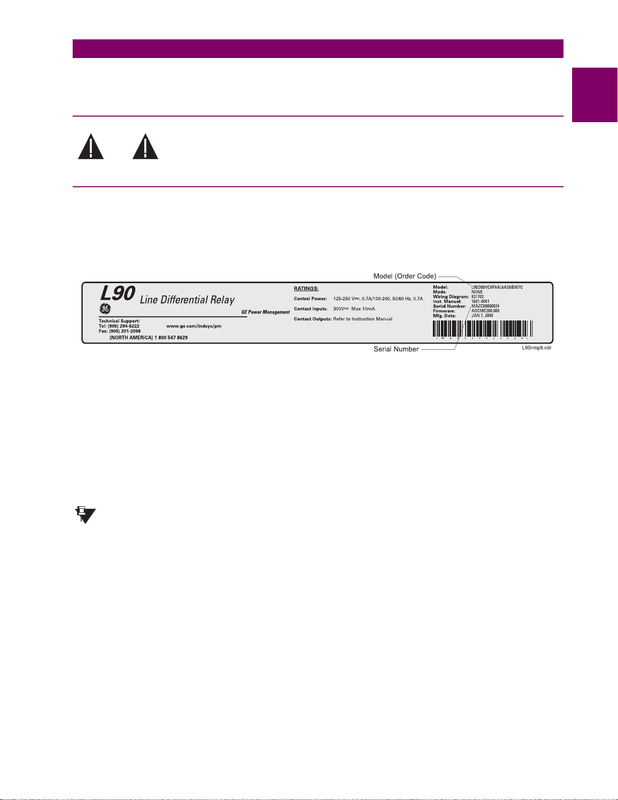
• View the rear name-plate and verify that the correct model has been ordered.
or downtime.
1.1.2 INSPECTION CHECKLIST
1
Figure 1–1: REAR NAME-PLATE (EXAMPLE)
• Ensure that the following items are included:
• Instruction Manual
• Products CD (includes URPC software and manuals in PDF format)
• mounting screws
• registration card (attached as the last page of the manual)
• Fill out the registration form and mail it back to GE Power Management (include the serial number located on the rear
nameplate).
• For product information, instruction manual updates, and the latest software updates, please visit the GE Power Man-
agement Home Page.
If there is any noticeable physical damage, or any of the contents listed are missing, please contact GE
Power Management immediately.
NOTE
GE POWER MANAGEMENT
GE Power Management
215 Anderson Avenue
Markham, Ontario
Canada L6E 1B3
TELEPHONE: (905) 294-6222, 1-800-547-8629 (North Ame ric a only )
FAX: (905) 201-2098
E-MAIL: info.pm@indsys.g e.c om
HOME PAGE: http://www.GEindustrial.com/pm
CONTACT INFORMATION AND CALL CENTER FOR PRODUCT SUPPORT:
GE Power Management
L90 Line Differential Relay 1-1
Page 14

1.2 UR OVERVIEW 1 GETTING STARTED
1.2 UR OVERVIEW 1.2.1 INTRODUCTION TO THE UR RELAY
1
Historically, substation protection, control, and metering functions were performed with electromechanical equipment. This
first generation of equipment was gradually replaced by analog electronic equipment, most of which emulated the singlefunction approach of their electromechanical precursors. Both of these technologies required expensive cabling and auxiliary equipment to produce functioning systems.
Recently, digital electronic equipment has begun to provide protection, control, and metering functions. Initially, this equipment was either single function or had very limited multi-function capability, and did not significantly reduce the cabling and
auxiliary equipment required. However, recent digital relays have become quite multi-functional, reducing cabling and auxiliaries significantly. These devices also transfer data to central control facilities and Human Machine Interfaces using electronic communications. The functions performed by these products have become so broad that many users now prefer the
term IED (Intelligent Electronic Device).
It is obvious to statio n desig ners that the amou nt of cabl ing and au xilia ry eq uipme nt inst alled in station s can be even furth er
reduced, to 20% to 70% of the levels common in 1990, to achieve large cost reductions. This requires placing even more
functions within the IEDs.
Users of power equipment are also interested in reducing cost by improving power quality and personnel productivity, and
as always, in increasing system reliability and efficiency. These objectives are realized through software which is used to
perform functions at both the station and supervisory levels. The use of these systems is growing rapidly.
High speed communications are required to meet the data transfer rates required by modern automatic control and monitoring systems. In the near future, very high speed communications will be required to perform protection signaling with a
performance target response time for a command signal between two IEDs, from transmission to reception, of less than 5
milliseconds. This has been established by the Electric Power Research Institute, a collective body of many American and
Canadian power utilities, in their Utilities Communications Architecture 2 (MMS/UCA2) project. In late 1998, some European utilities began to show an interest in this ongoing initiative.
IEDs with the capabilities outlined above will also provide significantly more power system data than is presently available,
enhance operations and maintenance, and permit the use of adaptive system configuration for protection and control systems. This new generation of equipment must also be easily incorporated into automation systems, at both the station and
enterprise levels. The GE Power Management Universal Relay (UR) has been developed to meet these goals.
1-2 L90 Line Differential Relay
GE Power Management
Page 15

1 GETTING STARTED 1.2 UR OVERVIEW
1.2.2 UR HARDWARE ARCHITECTURE
Input Elements
Contact Inputs Contact Outputs
Virtual Inputs
Analog Inputs
CT Inputs
VT Inputs
Remote Inputs
Input
Status
Table
CPU Module Output Elements
Protective Elements
Logic Gates
Pickup
Dropout
Operate
Output
Status
Table
Virtual Outputs
Analog Outputs
Remote Outputs
-DNA
-USER
LAN
Programming
Device
Figure 1–2: UR CONCEPT BLOCK DIAGRAM
a) UR BASIC DESIGN
The UR is a digital-based device containing a central processing unit (CPU) that handles multiple types of input and output
signals. The UR can communicate over a local area network (LAN) with an operator interface, a programming device, or
another UR device.
The CPU module contains firmware that provides protection elements in the form of logic algorithms, as well as programmable logic gates, timers, and latches for control features.
Input elements accept a variety of analog or digital signals from the field. The UR isolates and converts these signals into
logic signals used by the relay.
Output elements con vert and isolate the logic signa ls gene rated by th e rela y into di gital or an alog si gnals that can be used
to control field devices.
Operator
Interface
827822A1.CDR
1
b) UR SIGNAL TYPES
The contact inputs and outputs are digital signals associated with connections to hard-wired contacts. Both ‘wet’ and
‘dry’ contacts are supported.
The virtual inputs and outputs are digital signals associated with UR internal logic signals. Virtual inputs include signals
generated by the local user interface. The virtual outputs are outputs of FlexLogic™ equations used to customize the UR
device. Virtual outputs can also serve as virtual inputs to FlexLogic™ equations.
The analog inputs an d outpu ts are si gnals that are associat ed w i th tra ns duc ers , s uch as R esi st anc e Temperature Detectors (RTDs).
The CT and VT inputs refer to ana log current tran sfor mer and vo ltage tra nsform er signals us ed to moni tor AC power lines .
The UR supports 1A and 5 A CTs.
The remote inputs and outputs provide a means of sharing digital point state information between remote UR devices.
The remote outputs interface to the remote inputs of other UR devices. Remote outputs are FlexLogic™ operands inserted
into UCA2 GOOSE messages and are of two assignment types: DNA standard functions and USER defined functions.
GE Power Management
L90 Line Differential Relay 1-3
Page 16

1.2 UR OVERVIEW 1 GETTING STARTED
c) UR SCAN OPERATION
1
Read Inputs
Protection elements
serviced by sub-scan
Protective Elements
Solve Logic
Set Outputs
Figure 1–3: UR SCAN OPERATION
The UR device operates in a cyclic scan fashion. The UR reads the inputs into an input status table, solves the logic program (FlexLogic™ equati on), and then s ets e ach ou tput to the ap propriat e state in an ou tput st atus ta ble. An y resu lting t ask
execution is priority interrupt-driven.
PKP
DPO
OP
827823A1.CDR
1.2.3 UR SOFTWARE ARCHITECTURE
The firmware (software embedded in the relay) is designed in functional modules which can be installed in any relay as
required. This is achieved with Object-Oriented Design and Programming (OOD/OOP) techniques.
Object-Oriented techniques involve the use of ‘objects’ and ‘classes’. An ‘object’ is defined as “a logical entity that contains
both data and code that manipulates that data”. A ‘class’ is the generalized form of similar objects. By using this concept,
one can create a Protec ti on Cla ss w ith the Protec ti on El em ents as obj ec ts o f the cl ass s uch as Time Overcurrent, Instantaneous Overcurrent, Current Differential, Undervoltage, Overvoltage, Underfrequency, and Distance. These objects represent completely self-contained software modules. The same object-class concept can be used for Metering, I/O Control,
HMI, Communications, or any functional entity in the system.
Employing OOD/OOP in the software architecture of the Universal Relay achieves the same features as the hardware
architecture: modularity, scalability, and flexibility. The application software for any Universal Relay (e.g. Feeder Protection,
Transformer Protection, Distance Protection) is constructed by combining objects from the various functionality classes.
This results in a ’common look and feel’ across the entire family of UR platform-based applications.
1.2.4 IMPORTANT UR CONCEPTS
As described above, the arch itecture of th e UR rela y is different from prev ious de vice s. In orde r to achie ve a gen eral und erstanding of this device, some sections of Chapter 5 are quite helpful. The most important functions of the relay are contained in "Elements". A description of UR elements can be found in the INTRODUCTION TO ELEMENTS section. An
example of a simple element, and some of the organization of this manual, can be found in the DIGITAL ELEMENTS
MENU section. An explanation of the use of inputs from CTs and VTs is in the INTRODUCTION TO AC SOURCES section.
A description of how digital signals are used and routed within the relay is contained in the INTRODUCTION TO FLEXLOGIC™ section.
1-4 L90 Line Differential Relay
GE Power Management
Page 17

1 GETTING STARTED 1.3 URPC SOFTWARE
1.3 URPC SOFTWARE 1.3.1 PC REQUIREMENTS
The Faceplate keypad and display or the URPC software interface can be used to communicate with the relay.
The URPC software interface is the preferred method to edit settings and view actual values because the PC monitor can
display more information in a simple comprehensible format.
The following minimum requirements must be met for the URPC software to properly operate on a PC.
Processor: Intel
RAM Memory: 64 MB minimum (128 MB recommended)
Hard Disk: 50 MB free space required before installation of URPC software
O/S: Windows
Device: CD-ROM drive
Port: COM1(2) / Ethernet
Refer to the following procedure to install the URPC software:
1. Start the Windows
2. Insert the URPC software CD into the CD-ROM drive.
3. If the installation program does not start automatically, choose Run from the Windows® Start menu and type
D:\SETUP.EXE. Press Enter to start the installation.
4. Follow the on-screen instructions to install the URPC software. When the Welcome window appears, click on Next to
continue with the installation procedure.
5. When the Choose Destination Location window appears and if the software is not to be located in the default direc-
tory, click Browse and type in the complete path name including the new directory name.
6. Click Next to continue with the installation procedure.
7. The default program group where the application will be added to is shown in the Select Program Folder window. If it
is desired that the application be added to an already existing program group, choose the group name from the list
shown.
8. Click Next to begin the installation process.
9. To launch the URPC application, click Finish in the Setup Complete window.
10. Subsequently, double click on the URPC software icon to activate the application.
Refer to the HUMAN INTERFACES chapter in this manual and the URPC Software Help program for more
information about the URPC software interface.
NOTE
®
Pentium 300 or higher
®
NT 4.x or Windows® 9x/2000
®
operating system.
1.3.2 SOFTWARE INSTALLATION
1
GE Power Management
L90 Line Differential Relay 1-5
Page 18

1.3 URPC SOFTWARE 1 GETTING STARTED
1.3.3 CONNECTING URPC® WITH THE L90
1
This section is intended as a quick start guide to using the URPC software. Please refer to the URPC Help File and the
HUMAN INTERFACES chapter for more information.
a) CONFIGURING AN ETHERNET CONNECTION
Before starting, verify that the Ethernet network cable is properly connected to the Ethernet port on the back of the relay.
1. Start the URPC software. Enter the password "URPC" at the login password box.
2. Select the Help > Connection Wizard menu item to open the Connection Wizard. Click "Next" to continue.
3. Click the "New Interface" button to open the Edit New Interface window.
• Enter the desired interface name in the Enter Interface Name field.
• Select the "Ethernet" interface from the drop down list and press "Next" to continue.
4. Click the "New Device" button to open the Edit New Device Window.
• Enter the desired name in the Enter Interface Name field.
• Enter th e Modbus address o f the relay (fr om
PROTOCOL
• Enter the IP address (from
the
5. Click the " 4.1 Read Dev ice Inf ormation" button the n "OK" when the relay in formati on has been re ceiv ed. C lick "Next" to
continue.
6. Click the "New Site" button to open the Edit Site Name window.
• Enter the desired site name in the
7. Click the "OK" b utt on then click "F inish ". The ne w Site Lis t tree wil l be ad ded to th e Site Li st wi ndow (or O nline window)
located in the top left corner of the main URPC window.
The Site Device has now been configured for Ethernet communications. Proceed to Section c) CONNECTING TO THE
RELAY below to begin communications.
Ö
MODBUS SLAVE ADDRESS) in the
Enter TCPIP Address
SETTINGS Ö PRODUCT SETUP ÖØ COMMUNICATIONS ÖØ NETWORK Ö IP ADDRESS) in
field.
Enter Site Name
SETTINGS
Enter Modbus Address
field.
Ö
PRODUCT SETUP ÖØ COMMUNICATIONS ÖØ MODBUS
field.
b) CONFIGURING AN RS232 CONNECTION
Before starting, verify that the RS232 serial cable is properly connected to the RS232 port on the front panel of the relay.
1. Start the URPC software. Enter the password "URPC" at the login password box.
2. Select the
3. Click the "New Interface" button to open the Edit New Interface window.
• Enter the desired interface name in the
• Select the "RS232" interface from the drop down list and press "Next" to continue.
4. Click the "New Device" button to open the Edit New Device Window.
• Enter the desired name in the
• Enter the PC COM port number in the
5. Click "OK" then click "Next" to continue.
6. Click the "New Site" button to open the Edit Site Name window.
• Enter the desired site name in the
7. Click the "OK" b utt on then click "F inish ". The ne w Site Lis t tree wil l be ad ded to th e Site Li st wi ndow (or O nline window)
located in the top left corner of the main URPC window.
The Site Device has now been configured for RS232 communications. Proceed to Section c) CONNECTING TO THE
RELAY below to begin communications.
Help > Connection Wizard
Enter Interface Name
menu item to open the Connection Wizard. Click "Next" to continue.
Enter Interface Name
COM Port
Enter Site Name
field.
field.
field.
field.
1-6 L90 Line Differential Relay
GE Power Management
Page 19

1 GETTING STARTED 1.3 URPC SOFTWARE
c) CONNECTING TO THE RELAY
1. Select the Display Properties window through the Site List tree as shown below:
1
2. The Display Properties window will open with a flashing status indicator.
• If the indicator is red, click the Connect button (lightning bolt) in the menu bar of the Displayed Properties window.
3. In a few moments, the flashing light should turn green, indicating that URPC is communicating with the relay.
Refer to the HUMAN INTERFACES chapter in this manual and the URPC Software Help program for more
information about the URPC software interface.
NOTE
GE Power Management
L90 Line Differential Relay 1-7
Page 20

1.4 UR HARDWARE 1 GETTING STARTED
1.4 UR HARDWARE 1.4.1 MOUNTING AND WIRING
1
Please refer to the HARDWARE chapter for detailed relay mounting and wiring instructions. Review all WARNINGS AND
CAUTIONS.
1.4.2 COMMUNICATIONS
The URPC software communicates to the relay via the faceplate RS232 port or the rear panel RS485 / Ethernet ports. To
communicate via the faceplate RS232 port, a standard “straight-through” serial cable is used. The DB-9 male end is connected to the relay and the DB-9 or DB-25 female end is connected to the PC COM1 or COM2 port as described in the
HARDWARE chapter.
Figure 1–4: RELAY COMMUNICATIONS OPTIONS
To communicate through the L90 rear RS485 port from a PC RS232 port, the GE Power Management RS232/RS485 converter box is required. This device (catalog number F485) connects to the computer using a "straight-through" serial cable.
A shielded twisted-pair (20, 22, or 24 AWG) connects the F485 converter to the L90 rear communications port. The converter terminals (+, –, GND) are connected to the L90 communication module (+, –, COM) terminals. Refer to the CPU
COMMUNICATION PORTS section in the HARDWARE chapter for opti on details. The line shou ld b e te rmi nated with an RC network (i.e. 120 Ω, 1 nF) as described in the HARDWARE chapter.
1.4.3 FACEPLATE DISPLAY
All messages are display ed on a 2 × 20 characte r vacuum fluo rescen t displa y to make them visi ble unde r poor lighti ng conditions. Messages are displayed in English and do not require the aid of an instruction manual for deciphering. While the
keypad and display are not actively being used, the display will default to defined messages. Any high priority event driven
message will automatically override the default message and appear on the display.
1-8 L90 Line Differential Relay
GE Power Management
Page 21

1 GETTING STARTED 1.5 USING THE RELAY
1.5 USING THE RELAY 1.5.1 FACEPLATE KEYPAD
Display messages are organized into ‘pages’ under the following headings: Actual Values, Settings, Commands, and Targets. The key navigates through these pages. Each heading page is broken down further into logical subgroups.
The MESSAGE keys navigate through the subgro ups. The VALUE keys scroll increment or decreme nt
numerical setting values when in programming mode. These keys also scroll through alphanumeric values in the text edit
mode. Alternatively, values may also be entered with the numeric keypad.
The key initiates and adv ance to the next chara cte r in te xt e dit mod e or e nters a decimal poin t. The key may be
pressed at any time for context sensitive help messages. The key stores altered setting values.
1.5.2 MENU NAVIGATION
Press the key to select the desired header display page (top-level menu). The header title appears momentarily followed by a header display page menu item. Each press of the key advances through the main heading pages as
illustrated below.
Ö
Ö
ACTUAL VALUES SETTINGS COMMANDS
ØØØØ
ACTUAL VALUES
STATUS
SETTINGS
PRODUCT SETUP
Ö
Ö
COMMANDS
VIRTUAL INPUTS
Ö
Ö
TARGETS
No Active
Targets
1
Ö
Ö
USER DISPLAYS
when in use
(
Ø
User Display 1
The setting and actual value messages are arranged hierarchically. The header display pages are indicated by double
scroll bar characters (
pages represent the highest level of the hierarchy and the sub-header display pages fall below this level. The MESSAGE
and keys move within a group of headers, sub-headers, setting values, or actual values. Continually pressing the
MESSAGE key from a header display displays specific information for the header category. Conversely, continually
pressing the MESSAGE key from a setting value or actual value display returns to the header display.
HIGHEST LEVEL LOWEST LEVEL (SETTING VALUE)
SETTINGS
PRODUCT SETUP
SETTINGS
SYSTEM SETUP
)
1.5.3 MENU HIERARCHY
), while sub-header pages are indicated by single scroll bar characters (
PASSWORD
SECURITY
ACCESS LEVEL:
Restricted
). The head er displ ay
GE Power Management
L90 Line Differential Relay 1-9
Page 22

1.5 USING THE RELAY 1 GETTING STARTED
1.5.4 RELAY ACTIVATION
1
The relay is defaulted to the "Not Programmed" state when it leaves the factory. This safeguards against the installation of
a relay whose settings have not been entered. When powered up successfully, the TROUBLE indicator will be on and the
IN SERVICE indicator off. The relay in the "Not Programmed" state will block signaling of any output relay. These conditions will remain until the relay is explicitly put in the "Programmed" state.
Select the menu message
RELAY SETTINGS:
Not Programmed
To put the relay in the "Programmed" state, press either of the VALUE keys once and then press . The faceplate TROUBLE indicator will turn off and the IN SERVICE indicator will turn on. The settings for the relay can be programmed manually (refer to the SETTINGS chapter) via the faceplate keypad or remotely (refer to the URPC Help file) via
the URPC software interface.
The battery tab is installed in the power supply module before the L90 shipped from the factory. The battery tab prolongs
battery life in the event the relay is powered down for long periods of time before installation. The battery is responsible for
backing up event records, oscillography, data logger, and real-time clock information when the relay is powered off. The
battery failure self-te st error gen erated by the relay is a m inor and s hould no t af fect the rel ay functio nality. When the relay is
installed and ready for co mmis sioni ng, the tab sh ould be rem oved. The battery tab should be re-inserte d if the relay is powered off for an extended period of time. If required, contact the factory for a replacement battery or battery tab.
SETTINGS Ö PRODUCT SETUP ÖØ INSTALLATION Ö RELAY SETTINGS
1.5.5 BATTERY TAB
1.5.6 RELAY PASSWORDS
It is recommended that passwords be set up for each security level and assigned to specific personnel. There are two user
password SECURITY access levels:
1. COMMAND
The COMMAND access level restricts the user from making any settings changes, but allows the user to perform the following operations:
• operate breakers via faceplate keypad
• change state of virtual inputs
• clear event records
• clear oscillography records
2. SETTING
The SETTING access level allows the user to make any changes to any of the setting values.
Refer to the CHANGING SETTINGS section (in the HUMAN INTERFACES chapter) for complete instructions
on setting up security level passwords.
NOTE
1.5.7 FLEXLOGIC™ CUSTOMIZATION
FlexLogic™ equation editing is required for setting up user-defined logic for customizing the relay operations. See section
FLEXLOGIC™ in the SETTINGS chapter.
1.5.8 COMMISSIONING
Templated tables for charting all the required settings before entering them via the keypad are available in the COMMISSIONING chapter, which also includes instructions for commissioning tests.
1-10 L90 Line Differential Relay
GE Power Management
Page 23

2 PRODUCT DESCRIPTION 2.1 INTRODUCTION
2 PRODUCT DESCRIPTION 2.1 INTRODUCTION 2.1.1 OVERVIEW
The L90 relay is a digital current differential relay system with an integral communications channel interface.
The L90 is intended to provide complete protection for transmission lines of any voltage level. Both three phase and single
phase tripping schemes are available. Models of the L90 are available for application on both two and three terminal lines.
The L90 uses per phase differential at 64 kbps transmitting 2 phaselets per cycle. The current differential scheme is based
on innovative patented techniques developed by GE. The L90 algorithms are based on the Fourier transform–phaselet
approach and an adaptive statistical restraint. The restraint is similar to a traditional percentage differential scheme, but is
adaptive based on relay measurements. When used with a 64 kbps channel, the innovative “phaselets” approach yields an
operating time of 1.0 to 1.5 cycles typical. The adaptive statistical restraint approach provides both more sensitive and
more accurate fault sensin g. This al lows the L90 to dete ct relati vely higher im pedan ce sin gle line to gro und f aults th at existing systems may not. The basic current differential element operates on current input only. Long lines with significant
capacitance can ben efit from charg ing cu rrent com pens ation i f termin al vol tage me asurem ents a re appli ed to the relay. The
voltage input is also used for some protection and monitoring features such as directional elements, fault locator, metering,
and distance backup.
The L90 is designed to operate over different communications links with various degrees of noise encountered in power
systems and communications environments. Since correct operation of the relay is completely dependent on data received
from the remote end, special attention must be paid to information validation. The L90 incorporates a high degree of security by using a 32-bit CRC (cyclic redundancy code) inter-relay communications packet.
In addition to current differential protection, the relay provides multiple backup protection for phase and ground faults. For
overcurrent prot ect ion , th e time overcurrent c urve s may be s ele cte d fro m a selection of stan dard cu rve shapes or a custom
FlexCurve™ for optimum co-ordination. Additionally, one zone of phase and ground distance protection with power swing
blocking, out-of-step tripping, line pickup, load encroachment, and POTT features is included.
The L90 incorporates charging current compensation for applications on very long transmission lines without loss of sensitivity. The line capacitive current is removed from the terminal phasors.
The relay uses a sampling rate of 64 samples per cycle to provide metering values and flexible oscillography.
Voltage and current metering is included as a standard feature. Additionally, currents are available as total RMS values.
Power, power factor and frequency measurements are also provided.
Diagnostic feature s inc lude a seque nce of record s of 10 24 tim e-tagge d eve nts. Th e intern al cl ock u sed fo r time-tagg ing ca n
be synchronized with an IRIG-B signal. This precise time stamping allows the sequence of events to be determined
throughout the system. Events can also be programmed (via FlexLogic™ equations) to trigger oscillography data capture
which may be set to record the measured parameters before and after the event for viewing on a portable computer (PC).
These tools will significantly reduce troubleshooting time and simplify report generation in the event of system faults.
A faceplate RS232 port may be used to connect a PC for programming settings and for monitoring actual values. A variety
of communications modules are available. Two rear RS485 ports are standard to allow independent access by operating
and engineering staff. All serial ports use the Modbus
puters with baud rates up to 115.2 kbps. The RS232 port has a fixed baud rate of 19.2 kbps. Optional communications
modules include a 10BaseF Eth ern et interfa ce whic h can b e used t o provi de fast, reliabl e commu nicati ons in noisy enviro nments. Another option provides two 10BaseF fiber optic ports for redundancy. The Ethernet port supports MMS/UCA2 protocol.
The relay uses flash memory technology which allows field upgrading as new features are added.
The testing features can be used to verify and test settings and operations.
®
RTU protocol. The RS485 ports may be connected to system com-
2
GE Power Management
L90 Line Differential Relay 2-1
Page 24

2.1 INTRODUCTION 2 PRODUCT DESCRIPTION
2.1.2 FEATURES
LINE CURRENT DIFFERENTIAL:
• Phase segregated, high-speed digital current differential system
• Overhead and underground AC transmission lines, series compensated lines
• Two and three terminal line applications
2
• Zero-sequence removal for application on lines with tapped transformers connected in a grounded Wye on the line
side
• GE phaselets approach based on Discrete Fourier Transform with 64 samples per cycle and transmitting 2 timestamped phaselets per cycle
• Adaptive restraint approach improving sensitivity and accuracy of fault sensing
• Increased security for trip decision using Disturbance Detector and Trip Output logic
• Continuous clock synchronization via the distributed synchronization technique
• Increased transient stability through DC decaying offset removal
• Accommodates up to 5 times CT ratio differences
• Peer-to-Peer (Master-Master) architecture changing to Master-Slave via DTT (if channel fails) at 64 kbps
• Charging current comp ens ati on
• Interfaces direct fiber, multiplexed RS422 and G.703 connections with relay ID check
• Per phase line differential protection Direct Transfer Trip plus 8 user-assigned pilot signals via the communications
channel
• Secure 32-bit CRC protection against communications errors
BACKUP PROTECTION:
• DTT provision for pilot schemes
• 1 zone distance protection with POTT scheme, power swing blocking/out-of-step tripping, line pickup, and load
encroachment
• 2-element TOC and 2-element IOC directional phase overcurrent protection
• 2-element TOC and 2-element IOC directional zero sequence overcurrent protection
• 2-element TOC and 2-element IOC negative sequence overcurrent protection
• Undervoltage and overvoltage protection
ADDITIONAL PROTECTION:
• Breaker failure protection
• Stub bus protection
• VT and CT supervision
• GE "Sources" approach allowing grouping of different CTs and VTs from multiple input channels
• Open pole detection
• Breaker trip coil supervision and "seal-in" of trip command
• FlexLogic™ allowing creation of user-defined distributed protection and control logic
CONTROL:
• 1 and 2 breakers configuration for 1½ and ring bus schemes, pushbutton control from the relay
• Auto-reclosing and synchrochecking
• Breaker arcing current
2-2 L90 Line Differential Relay
GE Power Management
Page 25

2 PRODUCT DESCRIPTION 2.1 INTRODUCTION
MONITORING:
• Oscillography of current, voltage, FlexLogic™ operands, and digital signals (1× 128 cycles to 31 × 8 cycles config-
urable)
• Events recorder - 1024 events
• Fault locator
METERING:
• Actual 87L remote phasors, differential current and channel delay at all line terminals of line current differential protec-
tion
• Line current, voltage, real power, reactive power, apparent power, power factor, and frequency
COMMUNICATIONS:
• RS232 front port - 19.2 kbps
• 1 or 2 RS485 rear ports - up to 115 kbps
• 10BaseF Ethernet port supporting MMS/UCA2.0 protocol
2.1.3 FUNCTIONALITY
The following SINGLE LINE DIAGRAM illustrates relay functionality using ANSI (American National Standards Institute)
device numbers
2
52
Monitoring
50DD
(via Dedicated Communications)
79
CLOSE TRIP
51P(2)
51_2(2)
50_2(2)
50P(2)
Data From/To Remote End
L90 Line Differential Relay
Figure 2–1: SINGLE LINE DIAGRAM
50BF(2)
87L 21P
67P(2)
FlexElement
50G(2)
68
51G(2)
TM
78
Metering
50N(2)
51N(2)
Transducer
Inputs
59X
3V_0
21G67N/G
59P
27P(2)
59N
27X
25(2)
831706AS.CDR
GE Power Management
L90 Line Differential Relay 2-3
Page 26

2.1 INTRODUCTION 2 PRODUCT DESCRIPTION
T able 2–1: DEVICE NUMBERS AND FUNCTIONS
2
DEVICE
NUMBER
21G Ground Distance 51N Neutral Time Overcurrent
21P Phase Distance 51P Phase Time Overcurrent
25 Synchrocheck 51_2 Negative Sequence Time Overcurrent
27P Phase Undervoltage 52 AC Circuit Breaker
27X Auxiliary Undervoltage 59N Neutral Overvoltage
50BF Breaker Failure 59P Phase Overvoltage
50DD Adaptive Fault Detector
50G Ground Instantaneous Overcurrent 67P Phase Directional Overcurrent
50N Neutral Instantaneous Overcurrent 68 Power Swing Blocking
50P Phase Instantaneous Overcurrent 78 Out-of-step Tripping
50_2 Negative Sequence Instantaneous Overcurrent 79 Automatic Recloser
51G Ground Time Overcurrent 87L Segregated Line Current Differential
FUNCTION DEVICE
(sensitive current disturbance detector)
Table 2–2: ADDITIONAL DEVICE FUNCTIONS
FUNCTION FUNCTION FUNCTION
Breaker Arcing Current (I
Breaker Control FlexLogic™ Equations Pilot Scheme (POTT)
Contact Inputs (up to 96) L90 Channel T ests Setting Groups (8)
Contact Outputs (up to 64) Line Pickup Stub Bus
CT Failure Detector Load Encroachment Transducer I/O
Data Logger Metering: Current, Voltage, Power,
Digital Counters (8) User Programmable LEDs
Digital Elements (16) Virtual Inputs (32)
Direct Inputs (8 per L90 comms channel) MMS/UCA Communications Virtual Outputs (64)
DNP 3.0 MMS/UCA Remote I/O ("GOOSE") VT Fuse Failure
Event Recorder ModBus Communications
Fault Locator ModBus User Map
Fault Reporting O pen Pole Detector
2
T) FlexElements™ Oscillography
NUMBER
FUNCTION
59X Auxiliary Overvoltage
67N Neutral Directional Overcurrent
Energy, Frequency, Demand,
Power Factor, 87L differential
current, local & remote phasors
User Definable displays
2.1.4 ORDERING
The relay is available as a 19-inch rack horizontal mount unit or as a reduced size (¾) vertical mount unit, and consists of
power supply, CPU, Digital Input/Output, Trans ducer I/O an d L90 C ommunic ations modul es. Eac h of these can be supp lied
in a number of configurations which must be specified at the time of ordering. The information required to completely specify the relay is provided in the followin g table.
2-4 L90 Line Differential Relay
GE Power Management
Page 27

2 PRODUCT DESCRIPTION 2.1 INTRODUCTION
Table 2–3: ORDER CODES
L90 L90 -
Base Unit
CPU
Software
Mount /
Faceplate
Power
Supply
CT/VT
DSP
Digital I/O
Transducer
I/O (max of 4
per unit)
Inter-Relay
Communications
L90
00 - H C
00 - V F
| | ||| | | | | | | |
| | | | | | | | | | |
A
| | | | | | | | | | |
C
| | | | | | | | | | |
D
00
-F
- H
-F
||| | | | | | | |
| | | | | | | |
H C
| | | | | | | |
V F
|||||||
H
|||||||
L
8A
8C |
- L
- H
- L
| | | | | |
|
6A 6A 6A 6A 6A
6B 6B 6B 6B 6B
6C 6C 6C 6C 6C
6D 6D 6D 6D 6D
6E 6E 6E 6E 6E
6F 6F 6F 6F 6F
6G 6G 6G 6G 6G
6H 6H 6H 6H 6H
6K 6K 6K 6K 6K
6L 6L 6L 6L 6L
6M 6M 6M 6M 6M
6N 6N 6N 6N 6N
6P 6P 6P 6P 6P
6R 6R 6R 6R 6R
6S 6S 6S 6S 6S
6T 6T 6T 6T 6T
6U 6U 6U 6U 6U
5C 5C 5C 5C 5C |
5E 5E 5E 5E 5E |
5F 5F 5F 5F 5F |
N
S
|
XX XX XX XX
N
| | | |
_ _
U
For Full Sized Horizontal Mount
W
For Reduced Size Vertical Mount
R
Base Unit
RS485 + RS485 (ModBus RTU, DNP)
RS485 + 10BaseF (
RS485 + Redundant 10BaseF (
No Software Options
Horizontal (19” rack)
Vertical (3/4 size)
125 / 250 V AC/DC
24 to 48 V (DC only)
Standard 4CT/4VT
Standard 8CT
No Module
|
2 Form-A (Volt w/ opt Curr) & 2 Form-C outputs, 8 Digital Inputs
|
2 Form-A (Volt w/ opt Curr) & 4 Form-C Outputs, 4 Digital Inputs
|
8 Form-C Outputs
|
16 Digital Inputs
|
4 Form-C Outputs, 8 Digital Inputs
|
8 Fast Form-C Outputs
|
4 Form-A (Voltage w/ opt Current) Outputs, 8 Digital Inputs
|
6 Form-A (Voltage w/ opt Current) Outputs, 4 Digital Inputs
|
4 Form-C & 4 Fast Form-C Outputs
|
2 Form-A (Curr w/ opt Volt) & 2 Form-C Outputs, 8 Digital Inputs
|
2 Form-A (Curr w/ opt Volt) & 4 Form-C Outputs, 4 Digital Inputs
|
4 Form-A (Current w/ opt Voltage) Outputs, 8 Digital Inputs
|
6 Form-A (Current w/ opt Voltage) Outputs, 4 Digital Inputs
|
2 Form-A (No Monitoring) & 2 Form-C Outputs, 8 Digital Inputs
|
2 Form-A (No Monitoring) & 4 Form-C Outputs, 4 Digital Inputs
|
4 Form-A (No Monitoring) Outputs, 8 Digital Inputs
|
6 Form-A (No Monitoring) Outputs, 4 Digital Inputs
|
8 RTD Inputs
4 RTD Inputs, 4 dcmA Inputs
8 dcmA Inputs
820 nm, multi-mode, LED, 1 Channel
7A
1300 nm, multi-mode, LED, 1 Channel
7B
1300 nm, single-mode, ELED, 1 Channel
7C
1300 nm, single-mode, LASER, 1 Channel
7D
Channel 1: G.703; Channel 2: 820 nm, multi-mode LED
7E
Channel 1: G.703; Channel 2: 1300 nm, multi-mode LED
7F
Channel 1: G.703; Channel 2: 1300 nm, single-mode ELED
7G
Channel 1: G.703; Channel 2: 1300 nm, single-mode LASER
7Q
820 nm, multi-mode, LED, 2 Channels
7H
1300 nm, multi-mode, LED, 2 Channels
7I
1300 nm, single-mode, ELED, 2 Channels
7J
1300 nm, single-mode, LASER, 2 Channels
7K
Channel 1 - RS422; Channel 2 - 820 nm, multi-mode, LED
7L
Channel 1 - RS422; Channel 2 - 1300 nm, multi-mode, LED
7M
Channel 1 - RS422; Channel 2 - 1300 nm, single-mode, ELED
7N
Channel 1 - RS422; Channel 2 - 1300 nm, single-mode,
7P
G.703, 1 Channel
7R
RS422, 1 Channel
7T
G.703, 2 Channels
7S
RS422, 2 Channels
W
7
1550 nm, single-mode, LASER, 1 Channel
72
1550 nm, single-mode, LASER, 2 Channel
73
Channel 1 - RS422; Channel 2 - 1550 nm, single-mode, LASER
74
Channel 1 - G.703, Channel 2 - 1550 nm, single -mode, LASER
75
MMS/UCA2, Modbus TCP/IP, DNP
MMS/UCA2, Modbus TCP/IP, DNP
)
LASER
)
2
GE Power Management
L90 Line Differential Relay 2-5
Page 28

2.1 INTRODUCTION 2 PRODUCT DESCRIPTION
The order codes for replacement modules to be ordered separately are shown in the following table. When ordering a
replacement CPU module or Faceplate, please provide the serial number of your existing unit.
Table 2–4: ORDER CODES FOR REPLACEMENT MODULES
-
POWER SUPPLY
UR
CPU
2
FACEPLATE
DIGITAL I/O
CT/VT DSP
L60 INTER-RELAY
COMMUNICATIONS
L90 INTER-RELAY
COMMUNICATIONS
TRANSDUCER I/O
-
| 1H |
| 1L |
|9A|
|9C|
|9D|
| 3C |
| 3F |
|6A|
|6B|
|6C|
|6D|
|6E|
|6F|
|6G|
|6H|
|6K|
|6L|
|6M|
|6N|
|6P|
|6R|
|6S|
|6T|
|6U|
| 8A |
| 8B |
| 8C |
| 8D |
| 8Z |
|7U|
|7V|
|7Y|
|7Z|
| 7A |
| 7B |
| 7C |
| 7D |
| 7E |
| 7F |
| 7G |
| 7Q |
| 7H |
| 7I |
| 7J |
| 7K |
| 7L |
| 7M |
| 7N |
| 7P |
| 7R |
| 7S |
| 7T |
| 7W |
| 72 |
| 73 |
| 74 |
| 75 |
|5C|
|5E|
|5F|
125 / 250 V AC/DC
24 - 48 V (DC only)
RS485 + RS485 (ModBus RTU, DNP 3.0)
RS485 + 10BaseF (MMS/UCA2, ModBus TCP/IP, D NP 3.0)
RS485 + Redundant 10BaseF (MMS/UCA2, ModBus TCP/IP, DNP 3.0)
Horizontal Faceplate with Display & Keypad
Vertical Faceplate with Display & Keypad
2 Form-A (Voltage w/ opt Current) & 2 Form-C Outputs, 8 Digital Inputs
2 Form-A (Voltage w/ opt Current) & 4 Form-C Outputs, 4 Digital Inputs
8 Form-C Outputs
16 Digital Inputs
4 Form-C Outputs, 8 Digital Inputs
8 Fast Form-C Outputs
4 Form-A (Voltage w/ opt Current) Outputs, 8 Digital Inputs
6 Form-A (Voltage w/ opt Current) Outputs, 4 Digital Inputs
4 Form-C & 4 Fast Form-C Outputs
2 Form-A (Current w/ opt Voltage) & 2 Form-C Outputs, 8 Digital Inputs
2 Form-A (Current w/ opt Voltage) & 4 Form-C Outputs, 4 Digital Inputs
4 Form-A (Current w/ opt Voltage) Outputs, 8 Digital Inputs
6 Form-A (Current w/ opt Voltage) Outputs, 4 Digital Inputs
2 Form-A (No Monitoring) & 2 Form-C Outputs, 8 Digital Inputs
2 Form-A (No Monitoring) & 4 Form-C Outputs, 4 Digital Inputs
4 Form-A (No Monitoring) Outputs, 8 Digital Inputs
6 Form-A (No Monitoring) Outputs, 4 Digital Inputs
Standard 4CT/4VT
Sensitive Ground 4CT/4VT
Standard 8CT
Sensitive Ground 8CT
HI-Z 4CT
110/125 V, 20 mA Input/Output Channel Interface
48/60 V, 20 mA Input/Output Channel Interface
125 V Input, 5V Output, 20 mA Channel Interface
5 V Input, 5V Output, 20 mA Channel Interface
820 nm, multi-mode, LED, 1 Channel
1300 nm, multi-mode, LED, 1 Channel
1300 nm, single-mode, ELED, 1 Channel
1300 nm, single-mode, LASER, 1 Channel
Channel 1: G.703; Channel 2: 820 nm, multi-mode LED
Channel 1: G.703; Channel 2: 1300 nm, multi-mode LED
Channel 1: G.703; Channel 2: 1300 nm, single-mode ELED
Channel 1: G.703; Channel 2: 820 nm, single-mode LASER
820 nm, multi-mode, LED, 2 Channels
1300 nm, multi-mode, LED, 2 Channels
1300 nm, single-mode, ELED, 2 Channels
1300 nm, single-mode, LASER, 2 Channels
Channel 1 - RS422; Channel 2 - 820 nm, multi-mode, LED
Channel 1 - RS422; Channel 2 - 1300 nm, multi-mode, LED
Channel 1 - RS422; Channel 2 - 1300 nm, single-mode, ELED
Channel 1 - RS422; Channel 2 - 1300 nm, single-mode, LASER
G.703, 1 Channel
G.703, 2 Channels
RS422, 1 Channel
RS422, 2 Channels
1550 nm, single-mode, LASER, 1 Channel
1550 nm, single-mode, LASER, 2 Channel
Channel 1 - RS422; Channel 2 - 1550 nm, single-mode, LASER
Channel 1 - G.703, Channel 2 - 1550 nm, single -mode, LASER
8 RTD Inputs
4 dcmA Inputs, 4 RTD Inputs
8 dcmA Inputs
2-6 L90 Line Differential Relay
GE Power Management
Page 29

2 PRODUCT DESCRIPTION 2.2 PILOT CHANNEL
2.2 PILOT CHANNEL 2.2.1 INTER-RELAY COMMUNICATIONS
Dedicated inter-relay communications may operate over 64 kbps digital channels or dedicated fiber optic channels. Available interfaces inclu de:
• RS422 at 64 kbps
• G.703 at 64 kbps
• Dedicated fiber optics at 64 kbps. The fiber optic options include:
• 820 nm multi-mode fiber with an LED transmitter
• 1300 nm multi-mode fiber with an LED transmitter
• 1300 nm single-mode fiber with an ELED transmitter
• 1300 nm single-mode fiber with a LASER transmitter
• 1550 nm single-mode fiber with a LASER transmitter
All fiber optic options use an ST connector. L90 models are available for use on two or three terminal lines. A two terminal
line application requires one bi-directional channel. However, in two terminal line applications, it is also possible to use an
L90 relay with two bi-directional channels. The second bi-directional channel will provide a redundant backup channel with
automatic switchover if the first channel fails.
The L90 current differential relay is designed to function in a Peer to Peer or Master–Master architecture. In the Peer to
Peer architecture, all relays in the system are identical and perform identical functions in the current differential scheme. In
order for every relay on t he l ine to be a Peer, each relay must be able to communicate with all o f the other relays. If there i s
a failure in communications among the relays, the relays will revert to a Master - Slave architecture, with the Master as the
relay that has current phasors from all terminals. The use of two different operational modes is intended to increase the
dependability of the current differential scheme by reducing reliance on the communications.
The main difference between a Master and a Slave L90 is that only a Master relay performs the actual current differential
calculation, and only a Master relay communicates with the relays at all other terminals of the protected line.
At least one Master L90 relay must have live communications to all other terminals in the current differential scheme; the
other L90 relays on that line may operate as Slave relays. All Master relays in the scheme will be equal, and each will perform all functions. Each L9 0 rela y in the sche me wil l determ ine if it is a Master by com par ing the nu mber of te rminal s on the
line to the number of active communication channels.
The Slave terminals only communicate with the Master; there is no Slave to Slave communications path. As a result, a
Slave L90 relay cannot calculate the differential current. When a Master L90 relay issues a local trip signal, it also sends a
Direct Transfer Trip signal to all of the other L90 relays on the protected line.
If a Slave L90 relay issues a trip from one of its backup functions, it can send a transfer trip signal to its Master and other
Slave relays if such option is designated. Because a Slave cannot communicate with all the relays in the differential
scheme, the Master will then “broadcast” the Direct Transfer Trip signal to all other terminals.
The Slave L90 Relay performs the following functions:
• Samples currents and voltages
• Removes DC offset from the current via the mimic algorithm
• Creates phaselets
• Calculates sum of squares data
• Transmits current data to all Master L90 relays
• Performs all local relaying functions
• Receives Current Differential DTT and Direct Input signals from all other L90 relays
• Transmits Direct Output signals to all communicating relays
• Sends synchronization information of local clock to all other L90 clocks
The Master L90 Relay performs the following functions:
• Performs all functions of a Slave L90
• Receives current phasor inform ati on fr om all relay s
• Performs the Current Differential algorithm
• Sends a Current Differential DTT signal to all L90 relays on the protected line
2
GE Power Management
L90 Line Differential Relay 2-7
Page 30

2.2 PILOT CHANNEL 2 PRODUCT DESCRIPTION
In the Peer to Peer mode, all L90 relays act as Masters.
2
L90 - 1
L90 - 1
Tx
CHn
Rx
CHn
Tx
Rx
OPTIONAL REDUNDANT CHANNEL
TYPICAL 2-TERMINAL APPLICATION
Tx
CHn
Rx
Tx
CHn
Rx
Rx
Tx
Tx
CHn
CHn
L90 - 3
Rx
CHn
Tx
Rx
Tx
Rx
Tx
Rx
Tx
Rx
L90 - 2
CHn
CHn
L90 - 2
CHn
TYPICAL 3-TERMINAL APPLICATION
831009A4.CDR
Figure 2–2: COMMUNICATION PATHS DIAGRAM
2.2.2 CHANNEL MONITOR
The L90 has logic to detect that the communications channel is deteriorating or has failed completely. This can provide an
alarm indication and disable the current differential protection. Note that a failure of the communications from the Master to
a Slave does not prevent the Ma st er f rom p erforming the curre nt differential algori thm ; failure of the comm uni ca tions from a
Slave to the Master w ill pr event the Master f rom pe rform in g th e c orr ect current diff erential logic. Cha nne l propagation dela y
is being continuo us ly mea sur ed a nd a dj usted according to chan ges in the communication s p ath. Every relay on the p r otec tion system can assigned an unique ID to prevent advertent loopbacks at multiplexed channels.
2.2.3 LOOPBACK TEST
This option allows the user to test the relay at one terminal of the line by “looping” the transmitter output to the receiver
input; at the same time, the signal sent to the remote will not change. A local loopback feature is included in the relay to
simplify single ended testing.
2.2.4 DIRECT TRANSFER TRIPPING
The L90 includes provis ion for s ending and rece iving a sin gle-po le Direct Transfer Trip (DTT) signa l from cur rent diff erentia l
protection between the L90 relays at the terminals of the line using the pilot communications channel. The user may also
initiate an additional 8 pilot signals with an L90 communications channel to create trip/block/signaling logic. A FlexLogic™
operand, an external contact closure, or a signal over the LAN communication channels can be assigned for that logic.
2-8 L90 Line Differential Relay
GE Power Management
Page 31

2 PRODUCT DESCRIPTION 2.3 PROTECTION & CONTROL FUNCTIONS
2.3 PROTECTION & CONTROL FUNCTIONS 2.3.1 CURRENT DIFFERENTIAL PROTECTION
The current differential algorithms used in the L90 Line Differential Relay are based on the Fourier transform “phaselet”
approach and an adaptive statistical restraint. The L90 uses per phase differential at 64 kbps with 2 “phaselets” per cycle.
A detailed description of the current differential algorithms is found in the THEORY OF OPERATION chapter. The current
differential protection can be set in a percentage differential scheme with a single or dual slope.
2.3.2 BACKUP PROTECTION
In addition to the primary current differential protection, the L90 Line Differential Relay incorporates backup functions that
operate on the local relay current only, such as directional phase overcurrent, directional neutral overcurrent, negative
sequence overcurrent, undervoltage, overvoltage, and distance protection.
2.3.3 MULTIPLE SETTINGS GROUPS
The relay can store 8 sets of settings. They may be selected by user command, a configurable contact input or a FlexLogic™ equation to allow the relay to respond to changing conditions.
2.3.4 USER PROGRAMMABLE LOGIC
In addition to the built-in protection logic, the relay may be programmed by the user via FlexLogic™ equations.
2.3.5 CONFIGURABLE INPUTS AND OUTPUTS
All of the contac t converter inputs (Dig ita l In put s) to the relay ma y be as signed by the user to directly block a p r ote ct ion el ement, operate an output relay or serve as an input to FlexLogic™ equations. All of the outputs, except for the self test critical alarm contacts, may also be assigned by the user.
2
GE Power Management
L90 Line Differential Relay 2-9
Page 32

2.4 METERING & MONITORING FUNCTIONS 2 PRODUCT DESCRIPTION
2.4 METERING & MONITORING FUNCTIONS 2.4.1 METERING
The relay measures all input currents and calculates both phasors and symmetrical components. When AC potential is
applied to the relay via the optional voltage inputs, metering data includes phase and neutral current, phase voltage, three
phase and per phase W, VA, and var, and power factor. Frequency is measured on either current or voltage inputs. They
may be called onto the local display or accessed via a computer. All terminal current phasors and differential currents are
also displayed at all relays, allowing the user opportunity to analyze correct polarization of currents at all terminals.
2
The relay has a ‘sequence of events’ recorder which combines the recording of snapshot data and oscillography data.
Events consist of a broad range of change of state occurrences, including input contact changes, measuring-element
pickup and operation, FlexLogic™ equation changes, and self-test status. The relay stores up to 1024 events with the date
and time stamped to the nearest microsecond. This provides the information needed to determine a sequence of events,
which can reduce troubleshooting time and simplify report generation after system events.
The relay stores osc ill ography data at a sa mp lin g ra te o f 64 tim es per cy cl e. Th e re lay c an s to r e fro m 1 to 6 4 re co rds. Each
oscillography file includes a sampled data report consisting of:
• Instantaneous sample of the selected currents and voltages (if AC potential is used),
• The status of each selected contact input,
• The status of each selected contact output,
• The status of each selected measuring function,
• The status of various selected logic signals, including virtual inputs and outputs.
The captured oscillography data files can be accessed via the remote communications ports on the relay.
2.4.2 EVENT RECORDS
2.4.3 OSCILLOGRAPHY
2.4.4 CT FAILURE / CURRENT UNBALANCE ALARM
The relay has current unbalance alarm logic. The unbalance alarm may be supervised by a zero sequence voltage detector. The user may block the relay from tripping when the current unbalance alarm operates.
2.4.5 TRIP CIRCUIT MONITOR
On those outputs designed for trip duty, a trip voltage monitor will continuously measure the DC voltage across output contacts to determine if the associated trip circuit is intact. If the voltage dips below the minimum voltage or the breaker fails to
open or close after a trip command, an alarm can be activated.
2.4.6 SELF TEST
The most comprehensive self testing of the relay is performed during a power-up. Because the system is not performing
any protection activities at power-up, tests that would be disruptive to protection processing may be performed.
The processors in the CPU and all DSP modules participate in startup self-testing. Self-testing checks approximately 8590% of the hardware, and CRC/check- sum verification of all PROMs is performed. The processo rs communicate their
results to each ot her so that i f any f ailures ar e detec ted, th ey ca n be re ported t o the u ser. Each processor must successfull y
complete its self tests before the relay begins protection activities.
During both startup and normal operation, the CPU polls all plug-in modules and checks that every one answers the poll.
The CPU compares the module types that identify themselves to the relay order code stored in memory and declares an
alarm if a module is either non-responding or the wrong type for the specific slot.
When running under no rma l power system condit ion s, th e rel ay proc es so rs wi ll have “idle” time. Durin g thi s ti me , eac h p r ocessor performs “background” self-tests that are not disruptive to the foreground processing.
2-10 L90 Line Differential Relay
GE Power Management
Page 33

2 PRODUCT DESCRIPTION 2.5 OTHER FUNCTIONS
2.5 OTHER FUNCTIONS 2.5.1 ALARMS
The relay contains a dedicated alarm relay, the Critical Failure Alarm, housed in the Power Supply module. This output
relay is not user programmable. This relay has Form-C contacts and is energized under normal operating conditions. The
Critical Failure Alarm will become de-energized if the relay self test algorithms detect a failure that would prevent the relay
from properly protecting the transmission line.
2.5.2 LOCAL USER INTERFACE
The relay’s loca l user i nterfac e (on th e facep late) c onsists o f a 2 × 20 vacuum fl oresc ent dis play (VF D) and a 22 button keypad. The keypad and display may be used to view data from the relay, to change settings in the relay, or to perform control
actions. Also, the faceplate provides LED indications of status and events. The operation of the keypad is discussed in the
HUMAN INTERFACES chapter.
2.5.3 TIME SYNCHRONIZATION
The relay includes a clock which can run freely from the internal oscillator or be synchronized from an external IRIG-B signal. With the exter nal si gnal, a ll rela ys wire d to th e sam e syn chroni zing sig nal w ill be synchro nized to wi thin 0 .1 mil lisecon d.
2.5.4 FUNCTION DIAGRAMS
2
GE Power Management
Figure 2–3: L90 BLOCK DIAGRAM
L90 Line Differential Relay 2-11
Page 34

2.5 OTHER FUNCTIONS 2 PRODUCT DESCRIPTION
2
Clock
Clock
Control
Frequency
Deviation
Sampling Contol
Sample Currents
and Voltages
Time Stamp
Phase Deviation
Phase Deviation
Compute
Frequency
Deviation
Sample
Raw
Peer
Communication
Time
Stamps
Ping-pong
Algorithm
Estimate Phase Angle
Correction from Positive
Sequence Current Phasor
Remove Decaying
Offset and Charge
Compensation
Peer
Peer
Channel
Control
Estimate
Phase Angle
Uncertainties
Phase Angle
Uncertainties
Compute
Positive
Sequence
Currents
Phaselets
Window
Control
Disturbance
Detector
Window
Reset
Compute
Phaselets
Phaselets
Align Phaselets
Compute Phasors and
Variance Parameters
Fault
Detector
Figure 2–4: MAIN SOFT WARE MODULES
2-12 L90 Line Differential Relay
Phasors
Phaselets
swmoduls.cdr
Trip
Logic
GE Power Management
Page 35

2 PRODUCT DESCRIPTION 2.6 TECHNICAL SPECIFICATIONS
2.6 TECHNICAL SPECIFICATIONS
SPECIFICATIONS ARE SUBJECT TO CHANGE WITHOUT NOTICE
The operating times below include the activation time of a trip rated Form-A output contact unless otherwise indicated. FlexLogic™ operands of a given element are 4 ms faster. This should be taken into account when using
NOTE
FlexLogic™ to intercon nect wit h other pro tectio n or cont rol eleme nts of the relay, building FlexLogic™ equations, or
interfacing with other IEDs or power system devices via communications or different output contacts.
LINE CURRENT DIFFERENTIAL (87L)
Application: 2 or 3 terminal line, series compensated
line, tapped line, with charging current
compensation
Pickup Current Level: 0.20 to 4.00 pu in steps of 0.01
CT Tap (CT mismatch factor): 0.20 to 5.00 in steps of 0.01
Slope # 1: 1 to 50%
Slope # 2: 1 to 70%
Breakpoint between Slopes: 0.0 to 20.0 pu in steps of 0.1
DTT: Direct Transfer Trip (1 and 3 pole) to
remote L90
Operating Time: 1.0 to 1.5 power cycles duration
LINE CURRENT DIFFERENTIAL TRIP LOGIC
87L Trip: Adds security for trip decision; creates 1
& 3 pole trip logic
DTT: Enables Direct Transfer Trip (1 and 3
pole) from remote L90
DD: Sensitive Disturbance Detector to detect
fault occurrence
Stub Bus Protection: Security for ring bus and 1½ breaker
configurations
Open Pole Detector: Security for sequential and evolving
faults
PHASE DISTANCE
Characteristic: Dynamic (100% memory-polarized)
MHO or QUAD
Number of Zones: 1
Directionality: reversible
Reach (secondary Ω): 0.02 to 250.00 Ω in steps of 0.01
Reach Accuracy: ±5% including the effect of CVT tran-
sients up to an SIR of 30
Distance Characteristic Angle: 30 to 90° in steps of 1
Distance Comparator Limit Angle: 30 to 90° in steps of 1
Directional Supervision:
Characteristic Angle: 30 to 90° in steps of 1
Limit Angle: 30 to 90° in steps of 1
Right Blinder (QUAD only):
Reach: 0.02 to 250 Ω in steps of 0.01
Characteristic Angle: 60 to 90° in steps of 1
Left Blinder (QUAD only):
Reach: 0.02 to 250 Ω in steps of 0.01
Characteristic Angle: 60 to 90° in steps of 1
Time Delay: 0.000 to 65.535 s in steps of 0.001
Timing Accuracy: ±3% or 4 ms, whichever is greater
Current Supervision:
Level: line-to-line current
Pickup: 0.050 to 30.000 pu in steps of 0.001
Dropout: 97 to 98%
Memory Duration: 5 to 25 cycles in steps of 1
Voltage Supervision Pickup (series compensation applications):
Operation Time: 1 to 1.5 cycles (typical)
Reset Time: 1 power cycle (typical)
GROUND DISTANCE
Characteristic: Dynam ic (100% memory-polarized)
Number of Zones: 1
Directionality: reversible
Reach (secondary Ω): 0.02 to 250.00 Ω in steps of 0.01
Reach Accuracy: ±5% including the effect of CVT tran-
Distance Characteristic Angle: 30 to 90° in steps of 1
Distance Comparator Limit Angle: 30 to 90° in steps of 1
Directional Supervision:
Characteristic Angle: 30 to 90° in steps of 1
Limit Angle: 30 to 90° in steps of 1
Zero-Sequence Compensation
Z0/Z1 magnitude: 0.50 to 7.00 in steps of 0.01
Z0/Z1 angle: –90 to 90° in steps of 1
Zero-Sequence Mutual Compensation
Z0M/Z1 magnitude: 0.00 to 7.00 in steps of 0.01
Z0M/Z1 angle: –90 to 90° in steps of 1
Right Blinder (QUAD only):
Reach: 0.02 to 250 Ω in steps of 0.01
Characteristic Angle: 60 to 90° in steps of 1
Left Blinder (QUAD only):
Reach: 0.02 to 250 Ω in steps of 0.01
Characteristic Angle: 60 to 90° in steps of 1
Time Delay: 0.000 to 65.535 s in steps of 0.001
Timing Accuracy: ±3% or 4 ms, whichever is greater
Current Supervision:
Level: neutral current (3I_0)
Pickup: 0.050 to 30.000 pu in steps of 0.001
Dropout: 97 to 98%
Memory Duration: 5 to 25 cycles in steps of 1
Voltage Supervision Pickup (series compensation applications):
Operation Time: 1 to 1.5 cycles (typical)
Reset Time: 1 power cycle (typical)
2.6.1 PROTECTION ELEMENTS
2
0 to 5.000 pu in steps of 0.001
MHO, or QUAD
sients up to an SIR of 30
0 to 5.000 pu in steps of 0.001
GE Power Management
L90 Line Differential Relay 2-13
Page 36

2.6 TECHNICAL SPECIFICATIONS 2 PRODUCT DESCRIPTION
g
g
g
g
g
g
g
g
g
g
g
g
g
g
g
g
g
g
g
g
g
g
g
g
g
g
g
g
g
g
g
g
g
g
g
g
g
g
g
g
g
g
g
g
g
g
PHASE/NEUTRAL/GROUND TOC
Current: Phasor or RMS
Pickup Level: 0.000 to 30.000 pu in steps of 0.001
Dropout Level: 97% to 98% of Pickup
Level Accuracy:
for 0.1 to 2.0 × CT: ±0.5% of readin
2
for > 2.0 × CT: ±1.5% of readin
Curve Shapes: IEEE Moderately/Very/Extremely
Curve Multiplier: Time Dial = 0.00 to 600.00 in steps of
Reset Type: Instantaneous/T imed (per IEEE)
Accuracy: Operate at > 1.03 × Actual Pickup
Timin
(whichever is
Inverse; IEC (and BS) A/B/C and Short
Inverse; GE IAC Inverse, Short/Very/
Extremely Inverse; I
rammable); Definite Time (0.01 s base
curve)
0.01
±3.5% of operate time or ±½ cycle
(whichever is
or ±1% of rated
reater)
> 2.0 × CT ratin
2
reater)
PHASE/NEUTRAL/GROUND IOC
Pickup Level: 0.000 to 30.000 pu in steps of 0.001
Dropout Level: 97 to 98% of Pickup
Level Accuracy:
0.1 to 2.0 × CT ratin
> 2.0 × CT ratin
Overreach: <2%
Pickup Delay: 0.00 to 600.00 s in steps of 0.01
Reset Delay: 0.00 to 600.00 s in steps of 0.01
Operate Time: <20 ms at 3 × Pickup at 60 Hz
Accuracy: Operate at 1.5 × Pickup
Timin
: ±0.5% of reading or ±1% of rated
(whichever is
±1.5% of readin
±3% or ±4 ms (whichever is
reater)
NEGATIVE SEQUENCE TOC
Current: Phasor
Pickup Level: 0.000 to 30.000 pu in steps of 0.001
Dropout Level: 97% to 98% of Pickup
Level Accuracy: ±0.5% of readin
Curve Shapes: IEEE Moderately/Very/Extremely
Curve Multiplier (Time Dial): 0.00 to 600.00 in steps of 0.01
Reset Type: Instantaneous/T imed (per IEEE) and
Accuracy: Operate at > 1.03 × Actual Pickup
Timin
ever is
from 0.1 to 2.0 x CT ratin
±1.5% of reading > 2.0 x CT ratin
Inverse; IEC (and BS) A/B/C and Short
Inverse; GE IAC Inverse, Short/Very/
Extremely Inverse; I
rammable); Definite Time (0.01 s base
curve)
Linear
±3.5% of operate time or ±½ cycle
(whichever is
or ±1% of rated (which-
reater)
2
reater)
t; FlexCurve™ (pro-
reater)
t; FlexCurve™ (pro-
NEGATIVE SEQUENCE IOC
Pickup Level: 0.000 to 30.000 pu in steps of 0.001
Dropout Level: 97 to 98% of Pickup
Level Accuracy:
0.1 to 2.0 × CT ratin
(whichever is
> 2.0 × CT ratin
Overreach: < 2 %
Pickup Delay: 0.00 to 600.00 s in steps of 0.01
Reset Delay: 0.00 to 600.00 s in steps of 0.01
Operate Time: < 20 ms at 3 × Pickup at 60 Hz
Accuracy: Operate at 1.5 × Pickup
Timin
: ±0.5% of reading or ±1% of rated
reater)
: ±1.5% of readin
±3% or ± 4 ms (whichever is
reater)
PHASE DIRECTIONAL OVERCURRENT
Relay Connection: 90° (quadrature)
Quadrature Volta
ABC Phase Seq.: phase A (V
ACB Phase Seq.: phase A (V
Polarizin
Current Sensitivity Threshold: 0.05 pu
Characteristic An
le Accuracy: ±2°
An
Operation Time (FlexLo
Trippin
(reverse load, forward fault):< 12 ms, typically
Blockin
e:
Voltage Threshold: 0.000 to 3.000 pu in steps of 0.001
le: 0 to 359° in steps of 1
(forward load, reverse fault):< 8 ms, typically
), phase B (VCA), phase C (VAB)
BC
), phase B (VAC), phase C (VBA)
CB
ic™ Operands):
NEUTRAL DIRECTIONAL OVERCURRENT
Directionality: Co-existing forward and reverse
Polarizin
Polarizin
Polarizin
Operatin
Level Sensin
Characteristic An
Limit An
An
Offset Impedance: 0.00 to 250.00 Ω in steps of 0.01
Pickup Level: 0.05 to 30.00 pu in steps of 0.01
Dropuot Level: 97 to 98%
Operation Time: < 16 ms at 3 × Pickup at 60 Hz
:Volta
Voltage: V_0 or VX
Current: IG
Current: I_0
:3 × (|I_0| – K × |I_1|), K = 0.0625; IG
le: –90 to 90° in steps of 1
le: 40 to 90° in steps of 1, independent for
le Accuracy: ±2°
e, Current, Dual
forward and reverse
BREAKER FAILURE
Mode: 1-pole, 3-pole
Current Supv. Level: Phase, Neutral
Current Supv. Pickup: 0.001 to 30.000 pu in steps of 0.001
Current Supv. DPO: 97 to 98% of Pickup
Current Supv. Accuracy:
0.1 to 2.0 × CT ratin
> 2 × CT ratin
: ±0.75% of reading or ±1% of rated
(whichever is
: ±1.5% of readin
reater)
2-14 L90 Line Differential Relay
GE Power Management
Page 37

2 PRODUCT DESCRIPTION 2.6 TECHNICAL SPECIFICATIONS
g
g
g
g
g
g
g
g
g
g
g
g
g
g
g
ging
g
g
g
g
g
g
g
g
g
g
g
PHASE UNDERVOLTAGE
Voltage: Phasor only
Pickup Level: 0.000 to 3.000 pu in steps of 0.001
Dropout Level: 102 to 103% of Pickup
Level Accuracy: ±0.5% of readin
Curve Shapes: GE IAV Inverse;
Curve Multiplier: Time Dial = 0.00 to 600.00 in steps of
Accuracy: Operate at < 0.90 × Pickup
Timin
Definite Time (0.1s base curve)
0.01
±3.5% of operate time or ±4 ms (whichever is
from 10 to 208 V
reater)
PHASE OVERVOLTAGE
Voltage: Phasor only
Pickup Level: 0.000 to 3.000 pu in steps of 0.001
Dropout Level: 97 to 98% of Pickup
Level Accuracy: ±0.5% of readin
Pickup Delay: 0.00 to 600.00 in steps of 0.01 s
Operate Time: < 30 ms at 1.10 × Pickup at 60 Hz
Accuracy: ±3% or ±4 ms (whichever is greater)
Timin
from 10 to 208 V
NEUTRAL OVERVOL TAGE
Pickup Level: 0.000 to 1.250 pu in steps of 0.001
Dropout Level: 97 to 98% of Pickup
Level Accuracy: ±0.5% of readin
Pickup Delay: 0.00 to 600.00 s in steps of 0.01
Reset Delay: 0.00 to 600.00 s in steps of 0.01
Accuracy: ±3% or ±4 ms (whichever is greater)
Timin
Operate Time: < 30 ms at 1.10 × Pickup at 60 Hz
from 10 to 208 V
AUXILIARY UNDERVOLTAGE
Pickup Level: 0.000 to 3.000 pu in steps of 0.001
Dropout Level: 102 to 103% of Pickup
Level Accuracy: ±0.5% of readin
Curve Shapes: GE IAV Inverse
Definite Time
Curve Multiplier: Time Dial = 0 to 600.00 in steps of 0.01
Accuracy: ±3% of operate time or ±4 ms
Timin
(whichever is
from 10 to 208 V
reater)
AUXILIARY OVERVOLTAGE
Pickup Level: 0.000 to 3.000 pu in steps of 0.001
Dropout Level: 97 to 98% of Pickup
Level Accuracy: ±0.5% of readin
Pickup Delay: 0 to 600.00 s in steps of 0.01
Reset Delay: 0 to 600.00 s in steps of 0.01
Accuracy: ±3% of operate time or ±4 ms
Timin
Operate Time: < 30 ms at 1.10 × pickup at 60 Hz
(whichever is
from 10 to 208 V
reater)
LINE PICKUP
Phase IOC: 0.000 to 30.000 pu
Positive Sequence UV: 0.000 to 3.000 pu
Positive Seq. OV Delay: 0.000 to 65.535 s
SYNCHROCHECK
Max Volt Difference: 0 to 100000 V in steps of 1
Max An
Max Freq Difference: 0.00 to 2.00 Hz in steps of 0.01
Dead Source Function: None, LV1 & DV2, DV1 & LV2, DV1 or
le Difference: 0 to 100° in steps of 1
DV2, DV1 xor DV2, DV1 & DV2 (L=Live,
D=Dead)
AUTORECLOSURE
Single breaker applications, 3-pole tripping schemes.
Up to 4 reclose attempts before lockout.
Independent dead time settin
Possibility of chan
before each shot.
protection settings after each shot with
FlexLo
ic™.
POWER SWING DETECT
Functions: Power swing block, Out-of-step trip
Measured Impedance: Positive-sequence
& Tripping Modes: 2-step or 3-step
Blockin
Trippin
Mode: Early or Delayed
Current Supervision:
Pickup Level: 0.050 to 30.000 pu in steps of 0.001
Dropout Level: 97 to 98% of Pickup
Fwd / Reverse Reach (sec. Ω): 0.10 to 500.00 Ω in steps of 0.01
Impedance Accuracy: ±5%
Fwd / Reverse An
le Accuracy: ±2°
An
Characteristic Limit An
Timers: 0.000 to 65.535 s in steps of 0.001
Accuracy: ±3% or 4 ms, whichever is greater
Timin
le Impedances: 40 to 90° in steps of 1
les: 40 to 140° in steps of 1
LOAD ENCROACHMENT
Measured Impedance: Positive-sequence
Minumum Volta
Reach (sec. Ω): 0.02 to 250.00 Ω in steps of 0.01
Impedance Accuracy: ±5%
An
le: 5 to 50° in steps of 1
le Accuracy: ±2°
An
Pickup Delay: 0 to 65.535 s in steps of 0.001
Reset Delay: 0 to 65.535 s in steps of 0.001
Time Accuracy: ±3% or ±4 ms, whichever is
Operate Time: < 30 ms at 60 Hz
e: 0.000 to 3.000 pu in steps of 0.001
reater
2
GE Power Management
L90 Line Differential Relay 2-15
Page 38

2.6 TECHNICAL SPECIFICATIONS 2 PRODUCT DESCRIPTION
g
g
g
g
g
g
g
g
g
g
g
gg
g
g
g
g
g
g
g
gg
g
g
g
g
g
g
2.6.2 USER PROGRAMMABLE ELEMENTS
FLEXLOGIC™
Programming language: Reverse Polish Notation with graphical
Lines of code: 512
Number of Internal Variables: 64
Supported operations: NOT, XOR, OR (2 to 16 inputs), AND (2
2
Inputs: any lo
Number of timers: 32
Pickup delay: 0 to 60000 (ms, sec., min.) in steps of 1
Dropout delay: 0 to 60000 (ms, sec., min.) in steps of 1
visualization (keypad pro
to 16 inputs), NOR (2 to 16 inputs),
NAND (2 to 16 inputs), LATCH (Reset
dominant), EDGE DETECTORS, TIMERS
ical variable, contact, or virtual
input
FLEXCURVES™
Number: 2 (A and B)
Number of reset points: 40 (0 throu
Number of operate points: 80 (1 throu
Time delay: 0 to 65535 ms in steps of 1
h 1 of pickup)
h 20 of pickup)
rammable)
FLEXELEMENTS™
Number of elements: 8
Operatin
Operatin
Operatin
Compensation direction: Over, Under
Pickup Level: –30.000 to 30.000 pu in steps of 0.001
Hysteresis: 0.1 to 50.0% in steps of 0.1
Delta dt: 20 ms to 60 days
Pickup and dropout delay: 0.000 to 65.535 in steps of 0.001
signal: any analog actual value, or two values in
differential mode
signal mode: Signed or Absolute Value
mode: Level, Delta
FLEX STATES
Number: up to 256 logical variables grouped
rammability: any logical variable, contact, or virtual
Pro
under 16 Modbus addresses
input
USER-PROGRAMMABLE LEDS
Number: 48 plus Trip and Alarm
rammability: from any logical variable, contact, or vir-
Pro
Reset mode: Self-reset or Latched
tual input
USER-DEFINABLE DISPLAYS
Number of displays: 8
Lines of display: 2 × 20 alphanumeric characters
Parameters up to 5, any Modbus re
ister addresses
OSCILLOGRAPHY
Max. No. of Records: 64
Samplin
Tri
Data: AC input channels
Data Stora
Rate: 64 samples per power cycle
ers: Any element pickup, dropout or operate
Di
ital input change of state
ital output change of state
Di
ic™ equation
FlexLo
Element state
Di
ital input state
ital output state
Di
e: In non-volatile memory
EVENT RECORDER
Capacity: 1024 events
Time-ta
Tri
Data Stora
: to 1 microsecond
ers: Any element pickup, dropout or operate
Di
ital input change of state
ital output change of state
Di
Self-test events
e: In non-volatile memory
2.6.3 MONITORING
DATA LOGGER
Number of Channels: 1 to 16
Parameters: Any available analo
Samplin
Stora
Rate: 1 sec.; 1, 5, 10, 15, 20, 30, 60 min.
e Capacity: (NN is dependent on memory)
1-second rate: 01 channel for NN days
16 channels for NN days
↓↓
60-minute rate: 01 channel for NN days
16 channels for NN days
Actual Value
FAULT LOCATOR
Method: Single-ended
Maximum accuracy if: Fault resistance is zero or fault currents
from all line terminals are in phase
Relay Accuracy: ±1.5% (V > 10 V, I > 0.1 pu)
Worst-case Accuracy:
+ (user data)
VT
%error
CT
+ (user data)
%error
Z
Line%error
METHOD
RELAY ACCURACY
+ (user data)
+(Chapter 6)
%error
%error
+ (1.5%)
2-16 L90 Line Differential Relay
GE Power Management
Page 39

2 PRODUCT DESCRIPTION 2.6 TECHNICAL SPECIFICATIONS
g
g
g
g
g
g
g
g
g
g
g
g
g
g
g
2.6.4 METERING
RMS CURRENT: PHASE, NEUTRAL, AND GROUND
Accuracy at
0.1 to 2.0 × CT ratin
> 2.0 × CT ratin
: ±0.25% of reading or ±0.1% of rated
(whichever is
: ±1.0% of readin
reater)
RMS VOLTAGE
Accuracy: ±0.5% of reading from 10 to 208 V
APPARENT POWER VA
Accuracy: ±1.0% of readin
REAL POWER WATT
Accuracy: ±1.0% of reading at
–0.8 < PF ≤ –1.0 and 0.8 < PF ≤ 1.0
REACTIVE POWER VAR
Accuracy: ±1.0% of reading –0.2 ≤ PF ≤ 0.2
WATT-HOURS (POSITIVE & NEGATIVE)
Accuracy: ±2.0% of readin
Range: ±0 to 2 × 10⁹ MWh
Parameters: 3-phase only
Update Rate: 50 ms
AC CURRENT
CT Rated Primary: 1 to 50000 A
CT Rated Secondary: 1 A or 5 A by connection
Nominal Frequency: 20 to 65 Hz
Relay Burden: < 0.2 VA at rated secondary
Conversion Ran
Standard CT Module: 0.02 to 46 × CT ratin
Sensitive Ground Module:
Current Withstand: 20 ms at 250 times rated
e:
0.002 to 4.6 × CT ratin
1 sec. at 100 times rated
Cont. at 3 times rated
RMS symmetrical
RMS symmetrical
AC VOLTAGE
VT Rated Secondary: 50.0 to 240.0 V
VT Ratio: 0.1 to 24000.0
Nominal Frequency: 20 to 65 Hz
Relay Burden: < 0.25 VA at 120 V
Conversion Ran
e Withstand: cont. at 260 V to neutral
Volta
e: 1 to 275 V
1 min./hr at 420 V to neutral
VAR-HOURS (POSITIVE & NEGATIVE)
Accuracy: ±2.0% of readin
Range: ±0 to 2 × 10⁹ Mvarh
Parameters: 3-phase only
Update Rate: 50 ms
DEMAND
Measurements: Phases A, B, and C present and maxi-
mum measured currents
3-Phase Power (P, Q, and S) present
and maximum measured currents
Accuracy: ±2.0%
FREQUENCY
Accuracy at
V = 0.8 to 1.2 pu: ±0.01 Hz (when volta
for frequency measurement)
I = 0.1 to 0.25 pu: ±0.05 Hz
I > 0.25 pu ±0.02 Hz (when current si
frequency measurement)
e signal is used
nal is used for
2.6.5 INPUTS
FOR L90, THE NOMINAL SYSTEM FREQUENCY SHOULD BE SELECTED AS 50 HZ
OR 60 HZ ONLY.
NOTE
CONTACT INPUTS
Dry Contacts: 1000 Ω maximum
Wet Contacts: 300 V DC maximum
Selectable Thresholds: 16 V, 30 V , 80 V, 140 V
nition Time: < 1 ms
Reco
Debounce Timer: 0.0 to 16.0 ms in steps of 0.5
IRIG-B INPUT
Amplitude Modulation: 1 to 10 V pk-pk
DC Shift: TTL
Input Impedance: 22 kΩ
2
GE Power Management
L90 Line Differential Relay 2-17
Page 40

2.6 TECHNICAL SPECIFICATIONS 2 PRODUCT DESCRIPTION
g
g
g
g
g
g
g
g
g
2.6.6 POWER SUPPLY
LOW RANGE
Nominal DC Voltage: 24 to 48 V at 3 A
Min./Max. DC Volta
NOTE: Low ran
e: 20 / 60 V
e is DC only.
HIGH RANGE
Nominal DC Voltage: 125 to 250 V at 0.7 A
2
Min./Max. DC Volta
Nominal AC Volta
Min./Max. AC Volta
e: 88 / 300 V
e: 100 to 240 V at 50/60 Hz, 0.7 A
e: 88 / 265 V at 48 to 62 Hz
FORM-A RELAY
Make and Carry for 0.2 sec.: 30 A as per ANSI C37.90
Carry Continuous: 6 A
Break at L/R of 40 ms: 0.25 A DC max.
Operate Time: < 4 ms
Contact Material: Silver alloy
FORM-A VOLTAGE MONITOR
Applicable Voltage: approx. 15 to 250 V DC
Trickle Current: approx. 1 to 2.5 mA
FORM-A CURRENT MONITOR
Threshold Current: approx. 80 to 100 mA
FORM-C AND CRITICAL FAILURE RELAY
Make and Carry for 0.2 sec: 10 A
Carry Continuous: 6 A
Break at L/R of 40 ms: 0.1 A DC max.
Operate Time: < 8 ms
Contact Material: Silver alloy
ALL RANGES
Volt Withstand: 2 × Highest Nominal Voltage for 10 ms
Voltage Loss Hold-Up:
Power Consumption: Typical = 35 VA; Max. = 75 VA
50 ms duration at nominal
INTERNAL FUSE
RATINGS
Low Range Power Supply: 7.5 A / 600 V
Hi
h Range Power Supply: 5 A / 600 V
INTERRUPTING CAPACITY
AC: 100 000 A RMS symmetrical
DC: 10 000 A
2.6.7 OUTPUTS
FAST FORM-C RELAY
Make and Carry: 0.1 A max. (resistive load)
Minimum Load Impedance:
INPUT
VOLTAGE
250 V DC 20 K
120 V DC 5 K
48 V DC 2 K
24 V DC 2 K
Note: values for 24 V and 48 V are the same due to a
required 95% volta
Operate Time: < 0.6 ms
INTERNAL LIMITING RESISTOR:
Power: 2 watts
Resistance: 100 ohms
2 W RESISTOR 1 W RE SI STO R
e drop across the load impedance.
IMPEDANCE
Ω
Ω
Ω
Ω
50 K
2 K
2 K
2 K
Ω
Ω
Ω
Ω
CONTROL POWER EXTERNAL OUTPUT
(FOR DRY CONTACT INPUT)
Capacity: 100 mA DC at 48 V DC
Isolation: ±300 Vpk
2.6.8 COMMUNICATIONS
RS232
Front Port: 19.2 kbps, Modbus® RTU
RS485
1 or 2 Rear Ports: Up to 115 kbps, Modbus® RTU, isolated
Typical Distance: 1200 m
ether at 36 Vpk
to
2-18 L90 Line Differential Relay
ETHERNET PORT
10BaseF: 820 nm, multi-mode, supports half-
duplex/full-duplex fiber optic with ST
connector
Redundant 10BaseF: 820 nm, multi-mode, half-duplex/full-
Power Bud
Max Optical Ip Power: –7.6 dBm
Typical Distance: 1.65 km
et: 10 db
duplex fiber optic with ST connector
GE Power Management
Page 41

2 PRODUCT DESCRIPTION 2.6 TECHNICAL SPECIFICATIONS
g
g
g
g
g
g
g
g
g
g
(
g
g
NOTE
2.6.9 INTER-RELAY COMMUNICATIONS
SHIELDED TWISTED PAIR INTERFACE OPTIONS
INTERFACE TYPE TYPICAL DISTANCE
RS422 1200 m
G.703 100 m
RS422 distance is based on transmitter power
and does not take into consideration the clock
NOTE
source provided by the user.
LINK POWER BUDGET
EMITTER, FIBER
TYPE
820 nm LED,
Multimode
1300 nm LED,
Multimode
1300 nm ELED,
lemode
Sin
1300 nm Laser,
Sin
lemode
1550 nm Laser,
Sin
lemode
TRANSMIT
POWER
–20 dBm –30 dBm 10 dB
–21 dBm –30 dBm 9 dB
–21 dBm –30 dBm 9 dB
–1 dBm –30 dBm 29 dB
+5 dBm –30 dBm 35 dB
RECEIVED
SENSITIVITY
POWER
BUDGET
These Power Budgets are calculated from the
manufacturer’s worst-case transmitter power
NOTE
and worst case receiver sensitivity.
MAXIMUM OPTICAL INPUT POWER
EMITTER, FIBER TYPE MAX. OPTICAL
820 nm LED, Multimode –7.6 dBm
1300 nm LED, Multimode –11 dBm
1300 nm ELED, Sin
1300 nm Laser, Sin
1550 nm Laser, Sin
lemode –14 dBm
lemode –14 dBm
lemode –14 dBm
INPUT POWER
TYPICAL LINK DISTANCE
EMITTER TYPE FIBER TYPE CONNECTOR
820 nm LED Multimode ST 1.65 km
1300 nm LED Multimode ST 3.8 km
1300 nm ELED Sin
1300 nm Laser Sin
1550 nm Laser Sin
lemode ST 11.4 km
lemode ST 64 km
lemode ST 105 km
TYPE
TYPICAL
DISTANCE
Typical distances listed are based on the following assumptions for system loss. As
actual losses will vary from one installation to
another, the distance covered by your system
may vary.
CONNECTOR LOSSES
ST Connector 2 dB
FIBER LOSSES
820 nm Multimode 3 dB/km
1300 nm Multimode 1 dB/km
1300 nm Sin
1550 nm Sin
Splice losses: One splice every 2 km,
:
lemode 0.35 dB/km
lemode 0.25 dB/km
SYSTEM MARGIN
TOTAL OF BOTH ENDS):
at 0.05 dB loss per splice.
:
3 dB additional loss added to calcula-
tions to compensate for all
other losses.
2
2.6.10 ENVIRONMENTAL
Operating Temperatures:
Cold: IEC 60028-2-1, 16 h at –40°C
Dry Heat: IEC 60028-2-2, 16 h at 85°C
GE Power Management
L90 Line Differential Relay 2-19
Humidity (noncondensing): IEC 60068-2-30, 95%, Variant 1, 6
Altitude: Up to 2000 m
Installatio n C a te
days
ory: II
Page 42

2.6 TECHNICAL SPECIFICATIONS 2 PRODUCT DESCRIPTION
g
g
g
g
g
g
g
2.6.11 TYPE TESTS
Electrical Fast Transient: ANSI/IEEE C37.90.1
IEC 61000-4-4
IEC 60255-22-4
Oscillatory Transient: ANSI/IEEE C37.90.1
Insulation Resistance: IEC 60255-5
2
Dielectric Stren
Electrostatic Dischar
e Immunity: EN 61000-4-5
Sur
RFI Susceptibility: ANSI/IEEE C37.90.2
th: IEC 60255-6
IEC 61000-4-12
ANSI/IEEE C37.90
e: EN 61000-4-2
IEC 61000-4-3
IEC 60255-22-3
Ontario Hydro C-5047-77
THERMAL
Products go through a 12 h burn-in process at 60°C
APPROVALS
UL approval pendin
CSA approval pendin
Manufactured under an ISO9000 Registered system.
Conducted RFI: IEC 61000-4-6
e Dips/Interruptions/Variations:
Volta
IEC 61000-4-11
IEC 60255-11
Power Frequency Ma
Vibration Tes t (sinusoidal): IEC 60255-21-1
Shock and Bump: IEC 60255-21-2
netic Field Immunity:
IEC 61000-4-8
Type test report available upon request.
NOTE
2.6.12 PRODUCTION TESTS
CE:
LVD 73/23/EEC: IEC 1010-1
EMC 81/336/EEC: EN 50081-2
EN 50082-2
2.6.13 APPROVALS
2.6.14 MAINTENANCE
Cleaning: Normally, cleaning is not required; but for situations where dust has accumulated on the faceplate display, a dry cloth can be
used.
2-20 L90 Line Differential Relay
GE Power Management
Page 43

3 HARDWARE 3.1 DESCRIPTION
3 HARDWARE 3.1 DESCRIPTION 3.1.1 PANEL CUTOUT
The relay is av ail abl e as a 19-inch ra ck ho riz ont al mount unit or as a red uc ed size (¾) vertic al m oun t un it, with a removabl e
faceplate. The modular design allows the relay to be easily upgraded or repaired by a qualified service person. The faceplate is hinged t o a llo w eas y ac ce ss to the rem ov abl e m odu les, and is itself rem ov ab le to a llo w mo unt ing on doors with lim ited rear depth. There is also a removable dust cover that fits over the faceplate, which must be removed when attempting
to access the keypad or RS232 communications port.
The vertical and horizontal case dimensions are shown below, along with panel cutout details for panel mounting. When
planning the location of your panel cutout, ensure that provision is made for the faceplate to swing open without interference to or from adjacent equipment.
The relay must be mounted such that the faceplate sits semi-flush with the panel or switchgear door, allowing the operator
access to the keypad and the RS232 communications port. The relay is secured to the panel with the use of four screws
supplied with the relay.
URSERIESURSERIES
e
3
GE Power Management
Figure 3–1: L90 VERTICAL MOUNTING AND DIMENSIONS
L90 Line Differential Relay 3-1
Page 44

3
3.1 DESCRIPTION 3 HARDWARE
Figure 3–2: L90 VERTICAL SIDE MOUNTING INSTALLATION
3-2 L90 Line Differential Relay
GE Power Management
Page 45

3 HARDWARE 3.1 DESCRIPTION
INCHES
(mm)
REMOTE MOUNTING
BEZEL OUTLINE
8x0.156 %%c
0.375
(9.5)
5.000
(127.0)
9.520
(241.8)
14.520
(368.8)
0.375
(9.5)
17.720
(450.1)
0.375
(9.5)
4.785
(121.5)
0.375
(9.5)
1.875
(47.6)
6.960
(176.8)
10.90"
(276.8)
TOP VIEW
9.80"
(248.9)
HORIZONTAL (19" 4RU)
8.97"
(227.8)
Brackets repositioned
for switchgear mtg.
17.52"
(445.0)
827704B3.DWG
7.13"
(181.1)
CUTOUT
17.75"
(450.8)
PANEL MOUNTING
18.37"
(466.6)
1.57"
(39.8)
4.00"
(101.6)
4x0.28" Dia.
(7.1)
19.00"
(482.6)
7.00"
(177.8)
FRONT VIEW
3
Figure 3–3: L90 VERTICAL SIDE MOUNTING REAR DIMENSIONS
Figure 3–4: L90 HORIZONTAL MOUNTING AND DIMENSIONS
GE Power Management
L90 Line Differential Relay 3-3
Page 46

3.1 DESCRIPTION 3 HARDWARE
3.1.2 MODULE WITHDRAWAL / INSERTION
Module withdrawal and insertion may only be performed when control power has been removed from the
WARNING
WARNING
The relay, being modular in design, allows for th e w i thd r awal an d i nsertion of modules. Modules must onl y b e re pla ce d wi th
like modules in their original factory configured slots.
The faceplate can be o pen ed to the le ft, on ce the sliding latch on the right side has been pushe d up, as s hown in the figu re
below. This allows for easy accessibility of the modules for withdrawal.
unit. Inserting an incorrect module type into a slot may result in personal injury, damage to the unit or connected equipment, or undesired operation!
Proper electrostatic discharge protection (i.e. a static strap) must be used when coming in contact with
modules while the relay is energized!
3
Figure 3–5: UR MODULE WITHDRAWAL/INSERTION
WITHDRAWAL: The ejector/inserter clips, located at the top and bottom of each module, must be pulled simultaneously to
release the module for removal. Before performing this action, control power must be removed from the relay. Record
the original location of the module to ensure that the same or replacement module is inserted into the correct slot.
INSERTION: Ensure that the correct module type is inserted into the correct slot position. The ejector/inserter clips
located at the top and at the bo ttom of e ach module must be in the di se nga ged pos iti on as the mod ul e is sm ooth ly ins erte d
into the slot. Once the clips have cleared the raised edge of the chassis, engage the clips simultaneously. When the clips
have locked into position, the module will be fully inserted.
Type 9C a nd 9D CP U m odu le s are equipped with 1 0Bas eT and 10BaseF Ethernet connec tors fo r c omm un ic ati ons .
These connectors must be individually disconnected from the module before the it can be removed from the chas-
NOTE
sis.
3-4 L90 Line Differential Relay
GE Power Management
Page 47

3 HARDWARE 3.1 DESCRIPTION
WARNING
3.1.3 REAR TERMINAL LAYOUT
Figure 3–6: REAR TERMINAL VIEW
Do not touch any rear terminals while the relay is energized!
3
3.1.4 REAR TERMINAL ASSIGNMENTS
The relay follows a convention with respect to terminal number assignments which are three characters long assigned in
order by module slot position, row number, and column letter. Two-slot wide modules take their slot designation from the
first slot position (nearest to CPU module) which is indicated by an arrow marker on the terminal block. See the following
figure for an example of rear terminal assignments.
GE Power Management
Figure 3–7: EXAMPLE OF MODULES IN F & H SLOTS
L90 Line Differential Relay 3-5
Page 48

3.2 WIRING 3 HARDWARE
3.2 WIRING 3.2.1 TYPICAL WIRING DIAGRAM
TYPICAL CONFIGURATION
THE AC SIGNAL PATH IS CONFIGURABLE
ABC
(5 Amp)
52
N
TRIPPING DIRECTION
3
TO
REMOTE
L90
twisted pairs
Ground at
Device end
( DC ONLY )
DC
AC or DC
Shielded
No. 10AWG
Minimum
MODULES MUST BE
GROUNDED IF
TERMINAL IS
PROVIDED
3a
F
IC5
DIGITAL I/O
DIGITAL I/O
4a
3c
3b
F
F
F
IC
IG5
IC1
8A / 8B
H
H
H
H
H
H
H
H
H
H
H
U
U
U
U
U
U
1a
F
IA5
5a
5c
6a
6c
5b
7a
7c
8a
8c
7b
8b
7a
7c
8a
8c
7b
8b
1c
1b
F
F
IA
IA1
CONTACT IN 5a
CONTACT IN 5c
CONTACT IN 6a
CONTACT IN 6c
CONTACT IN 7a
CONTACT IN 7c
CONTACT IN 8a
CONTACT IN 8c
CONTACT IN 7a
CONTACT IN 7c
CONTACT IN 8a
CONTACT IN 8c
2b
2a
F
F
IB
IB5
CURRENT INPUTS
COMMON 5b
COMMON 7b
SURGE
COMMON 7b
SURGE
2c
F
IB1
H
H
H
H
H
H
H
H
H
H
U
U
U
U
U
GE Power Management
L90 Line Differential Relay
L
CONTACT IN 1c
LL
1c
CONTACT IN 2a
LL
2a
CONTACT IN 2c
LL
2c
COMMON 1b
LL
1b
LL
CONTACT IN 3a
3a
LL
CONTACT IN 3c
3c
LL
CONTACT IN 4a
4a
4c
CONTACT IN 4c
LL
LL
COMMON 3b
3b
CONTACT IN 5a
LL
5a
LL
CONTACT IN 5c
5c
LL
CONTACT IN 6a
6a
CONTACT IN 6c
LL
6c
LL
5b
COMMON 5b
LL
CONTACT IN 7a
7a
LL
CONTACT IN 7c
7c
LL
CONTACT IN 8a
8a
CONTACT IN 8c
LL
8c
LL
7b
COMMON 7b
8b
L
FIBER
Tx1 Rx1
CHNL. 1
FIBER
Tx2 Rx2
CHNL. 2
1b
B
CRITICAL
B
1a
FAILURE
B
2b
3a
48 VDC
B
OUTPUT
3b
B
HI
B
5b
CONTROL
LO
B
6b
POWER
B
6a
B
SURGE
8a
B
FILTER
8b
D2a
D3a
D4a
COM
D3b
D4b
D5b
COM
D5a
D6a
D7b
GROUND BUS
7
COM
* Optional
SURGE
6
I/O
*
RS485
COM 1
RS485
COM 2
IRIG-B
SURGE
6D
DIGITAL I/O
L90 COM. W7A
1
POWER SUPPLY
9A
CPU
MODULE ARRANGEMENT
PFR
6
I/O
*
(front)
CONTACTS SHOWN
WITH NO
CONTROL POWER
6
I/O
I/O
*
(Rear View)
L
CONTACT IN 1a
1a
Figure 3–8: TYPICAL WIRING DIAGRAM
DB-9
F
IG
RS-232
F
IG1
F
VA
6G
6H
U
U
U
U
U
U
6K
DIGITAL I/O
6C
DIGITAL I/O
F
VA
VOLTAGE INPUTS
1
H
2
H
3
H
4
H
1
2
3
4
5
6
1
N
2
N
3
N
4
N
5
N
6
N
7
N
8
N
1
S
2
S
3
S
4
S
5
S
6
S
7
S
8
S
831702by.CDR
GS
JUMXLWKVBHT
6
*
8
6
CPU
CT/VT
I/O
F
F
F
F
VC
VB
VB
VC
CURRENT SUPV.
VOLT &
I
1a
H
1b
H
V
H
1c
I
H
2a
2b
H
V
H
2c
I
3a
H
3b
H
V
3c
H
I
4a
H
4b
H
V
4c
H
I
1a
U
1b
U
V
1c
U
I
2a
U
2b
U
V
2c
U
I
3a
U
3b
U
V
3c
U
I
4a
U
4b
U
V
4c
U
I
5a
U
5b
U
V
5c
U
I
6a
U
6b
U
V
6c
U
1a
N
1b
N
N
1c
2a
N
2b
N
2c
N
3a
N
3b
N
3c
N
4a
N
4b
N
4c
N
TXD RXD
5a
N
RXD TXD
5b
N
5c
N
SGND SGND
N
6a
N
6b
N
6c
7a
N
7b
N
N
7c
N
8a
CONNECTOR
8b
N
8c
N
1a
S
1b
S
S
1c
2a
S
2b
S
2c
S
3a
S
3b
S
3c
S
4a
S
4b
S
4c
S
5a
S
5b
S
5c
S
S
6a
S
6b
S
6c
7a
S
7b
S
S
7c
S
8a
8b
S
8c
S
DN
1
9
Power
Supply
TC
1
VOLTAGE SUPV.
TC
2
UR COMPUTER
8
1
1
3
22
33
2
44
20
55
7
66
6
77
4
5
88
99
22
9 PIN
PERSONAL
COMPUTER
25 PIN
CONNECTOR
This diagram is based on the following order code: L90-A00-HCL-F8A-H6G-L6D-N6K-S6C-U6H-W7A.
The purpose of this diagram is to provide an example of how the relay is typically wired, not specifi-
cally how to wire your own relay. Please refer to the following pages for examples to help you wire
your relay correctly based on your own relay configuration and order code.
OPTIONAL
7c
7a
6c
6a
5c
5a
4c
4b
CAUTION
3-6 L90 Line Differential Relay
GE Power Management
Page 49

3 HARDWARE 3.2 WIRING
CAUTION
3.2.2 DIELECTRIC STRENGTH RATINGS AND TESTING
a) RATINGS
The dielectric strength of UR module hardware is shown in the following table:
Table 3–1: DIELECTRIC STRENGTH OF UR MODULE HARDWARE
MODULE
TYPE
1 Power Supply High (+); Low (+); (–) Chassis 2000 V AC for 1 min.
1 Power Supply 48 V DC (+) and (–) Chassis 2000 V AC for 1 min.
1 Power Supply Relay Terminals Chassis 2000 V AC for 1 min.
2 Reserved for Future N/A N/A N/A
3 Reserved for Future N/A N/A N/A
4 Reserved for Future N/A N/A N/A
5 Analog I/O All except 8b Chassis < 50 V DC
6 Digital I/O All (See Precaution 2) Chassis 2000 V AC for 1 min.
7R L90 G.703 All except 2b, 3a, 7b, 8a Chassis 2000 V AC fo r 1 min.
7T L90 RS422 All except 6a, 7b, 8a Chassis < 50 V DC
8 CT/VT All Chassis 2000 V AC for 1 min.
9 CPU All except 7b Chassis < 50 VDC
MODULE FUNCTION TERMINALS DIELECTRIC STRENGTH
FROM TO
(AC)
(See Precaution 1)
(See Precaution 1)
(See Precaution 1)
3
b) TESTING
Filter networks and transient protection clamps are used in module hardware to prevent damage caused by high peak voltage transients, radio frequency interference (RFI) and electromagnetic interference (EMI). These protective components
can be damaged by application of the ANSI/IEEE C37.90 specified test voltage for a period longer than the specified one
minute. For testing of dielectric strength where the test interval may exceed one minute, always observe the following precautions:
Test Precautions:
1. The connection from ground to the Filter Ground (Terminal 8b) and Surge Ground (Terminal 8a) must be removed
before testing.
2. Some versions of the digital I/O module have a Surge Ground connection on Terminal 8b. On these module types, this
connection must be removed before testing.
3.2.3 CONTROL POWER
CONTROL POWER SUPPLIED TO THE RELAY MUST BE CONNECTED TO THE MATCHING POWER SUPPLY
RANGE OF THE RELAY. IF THE VOLTAGE IS APPLIED TO THE WRONG TERMINALS, DAMAGE MAY
OCCUR!
The power supply module can be ordered with either of two possible voltage ranges. Each range has a dedicated input
connection for proper operation. The ranges are as shown below (see the Technical Specifications section for details).
Table 3–2: CONTROL POWER VOLTAGE RANGE
RANGE NOMINAL VOLTAGE
LO 24 to 48 V (DC only)
HI 125 to 250 V
The power supply module provides power to the relay and supplies power for dry contact input connections.
GE Power Management
L90 Line Differential Relay 3-7
Page 50

3.2 WIRING 3 HARDWARE
3
Figure 3–9: CONTROL POWER CONNECTION
The power supply module provides 48 V DC power for dry contact input connections and a critical failure relay (see TYPICAL WIRING DIAGRAM). The critical failure relay is a Form-C that will be energized once control power is applied and the
relay has successfully booted up with no critical self-test failures. If any of the on-going self-test features detect a critical
failure or control power is lost, the relay will de-energize.
3.2.4 CT/VT MODULES
A CT/VT module may hav e vo ltag e i npu ts on channels 1 throug h 4 inc lu si ve , or ch ann els 5 thro ugh 8 inclusive. C han ne ls 1
and 5 are intended for connection to phase A, and are labeled as such in the relay. Channels 2 and 6 are intended for connection to phase B, and are labeled as such in the relay. Channels 3 and 7 are intended for connection to phase C and are
labeled as su ch in th e relay. Channels 4 a nd 8 are intended for c onn ec tio n t o a s in gle phase source . I f v ol tage , t his c ha nnel
is labelled the auxiliary voltage (VX). If current, this channel is intended for connection to a CT between a system neutral
and ground, and is labelled the ground current (IG).
a) AC CURRENT TRANSFORMER INPUTS
VERIFY THAT THE CONNECTION MADE TO THE RELAY NOMINAL CURRENT OF 1 A OR 5 A MATCHES
THE SECONDARY RATING OF THE CONNECTED CTs. UNMATCHED CTs MAY RESULT IN EQUIPMENT
CAUTION
DAMAGE OR INADEQUATE PROTECTION.
The CT/VT module may be ordered with a standard ground current input that is the same as the phase current inputs (type
8A) or with a sensitive ground input (type 8B) which is 10 times more sensitive (see the Technical Specifications section for
more details). Each AC current input has an isolating transformer and an automatic shorting mechanism that shorts the
input when the module is withdrawn from the chassis. There are no internal ground connections on the current inputs. Current transformers with 1 to 50000 A primaries and 1 A or 5 A secondaries may be used.
CT connections for both ABC and ACB phase rotations are identical as shown in the TYPICAL WIRING DIAGRAM.
The exact placement of a zero sequence CT so that ground fault current will be detected is shown below. Twisted pair
cabling on the zero sequence CT is recommended.
3-8 L90 Line Differential Relay
GE Power Management
Page 51

3 HARDWARE 3.2 WIRING
Figure 3–10: ZERO-SEQUENCE CORE BALANCE CT INSTALLATION
b) AC VOLTAGE TRANSFORMER INPUTS
The phase voltage channels are used for most metering and protection purposes. The auxiliary voltage channel is used as
input for the Synchrocheck and Volts/Hertz features.
3
5a
5c
~
~
VA
VA
VOLTAGE INPUTS
6c
6a
~
VB
7c
~
~
~
~
~
VX
VC
VB
VX
VC
IA5
1a
~
1b
~
IA
8A / 8B
IA1
1c
~
8a
7a
2c
2a
~
~
~
IB
IB5
IB1
CURRENT INPUTS
3a2b3b
~
IC5
4a
3c
~
~
~
IC
IG5
IC1
8c
Figure 3–11: CT/VT MODULE WIRING
1a
~
IA5
3a
1b
~
IA
~
IA1
~
~
IB
IB5
2b
2a
1c
3b
2c
~
IB1
3c
~
~
~
IC
IC5
IC1
4c
4b
4a
~
~
~
IG
IG5
IG1
CURRENT INPUTS
8C / 8D / 8Z
5a
~
IA5
6a
5c
5b
~
IA
~
~
~
IB
IB5
IA1
7b
~
~
~
IC
IB1
IC5
7a
6b
6c
Figure 3–12: CT MODULE WIRING
Wherever a tilde “~” symbol appears, substitute with the Slot Position of the module.
NOTE
4c
4b
~
~
IG
IG1
CTVTMDL.cdr
(P/O 827831A2.CDR)
8b
8a
7c
~
~
IG5
IC1
CTMDL8CD.cdr
(P/O 827831A1.CDR)
8c
~
~
IG
IG1
GE Power Management
L90 Line Differential Relay 3-9
Page 52

3.2 WIRING 3 HARDWARE
3.2.5 CONTACT INPUTS/OUTPUTS
Every digital input/output module has 24 terminal connections. They are arranged as 3 terminals per row, with 8 rows in
total. A given row of three terminals may be used for the outputs of one relay. For example, for Form-C relay outputs, the
terminals connect to the normally open (NO), normally closed (NC), and common contacts of the relay. For a Form-A output, there are options of using current or voltage detection for feature supervision, depending on the module ordered. The
terminal configuration for contact inputs is different for the two applications. When a digital I/O module is ordered with contact inputs, they are arrang ed in groups of four and use two rows of three termin als . Ideally, each input would be tot all y is olated from any oth er inp ut. H owe ver, this would require that e very input have two ded ic ate d term ina ls a nd limit the availabl e
number of contacts based on the available number of terminals. So, although each input is individually optically isolated,
each group of four inp uts us es a s in gle c om mo n as a reas on abl e c om pro mi se . Th is allows each grou p o f fo ur outputs to be
supplied by wet contacts from different voltage sources (if required) or a mix of wet and dry contacts.
The tables and diagrams on the following pages illustrate the module types (6A, etc.) and contact arrangements that may
be ordered for the rela y. Since an entire row is used for a single contact output, th e name is assigned u sin g th e m odu le sl ot
3
position and row number. However, since there are two contact inputs per row, these names are assigned by module slot
position, row number, and column position.
UR RELAY FORM-A OUTPUT CONTACTS
Some Form-A outputs inclu de c ircuits to monitor the DC voltag e ac ros s th e ou tput con tac t when it is ope n, an d the DC current through the outpu t co nta ct w he n i t is clo se d. Ea ch of th e monitors contains a le vel detector whose ou tput is set to logic
“On = 1” when the current in the circuit is above the threshold setting. The voltage monitor is set to “On = 1” when the current is above about 1 to 2.5 mA, and the current monitor is set to “On = 1” when the current exceeds about 80 to 100 mA.
The voltage monitor is intended to check the health of the overall trip circuit, and the current monitor can be used to seal-in
the output contact until an external contact has interrupted current flow. The block diagrams of the circuits are below above
for the Form-A outputs with:
a) optional voltage monitor
b) optional current monitor
c) with no monitoring
If Idc 80mA, Cont Op x Ion
~
otherwise Cont Op x Ioff
~#a
If Idc 1mA, Cont Op x Von
I
~#b
V
~#c
Both voltage and current monitoring
~
otherwise Cont Op x Voff
a) Voltage with optional
current monitoring
~#a
I
If Idc 1mA, Cont Op x Von
~#b
otherwise Cont Op x Voff
V
~#c
Voltage monitoring only
~
+
Load
-
+
Load
-
~#a
V
If Idc 80mA, Cont Op x Ion
b) Current with optional
voltage monitoring
c) No monitoring
~#b
I
~#c
Current monitoring only Both voltage and current monitoring
~#a
~#b
~#c
~
otherwise Cont Op x Ioff
+
Load
-
+
Load
-
Figure 3–13: FORM-A CONTACT FUNCTIONS
3-10 L90 Line Differential Relay
~#a
V
~#b
I
~#c
(external jumper a-b is required)
If Idc 80mA, Cont Op x Ion
~
otherwise Cont Op x Ioff
If Idc 1mA, Cont Op x Von
~
otherwise Cont Op x Voff
827821A4.CDR
GE Power Management
+
Load
-
Page 53

3 HARDWARE 3.2 WIRING
WARNING
The operation of voltage and current monitors is reflected with the corresponding FlexLogic™ operands (Cont Op # Von,
Cont Op # Voff, Cont Op # Ion, and Cont Op # Ioff) which can be used in protection, control and alarm logic. The typical
application of the voltage monitor is Breaker Trip Circuit Integrity monitoring; a typical application of the Current monitor is
seal-in of the control command. Refer D IG ITAL ELEMENTS section for an examp le of h ow Fo rm A contacts can be app lie d
for Breaker Trip Circuit Integrity Monitoring.
Relay contacts must be considered unsafe to touch when the unit is energized!! If the relay contacts need
to be used for low voltage accessible applications, it is the customer’s responsibility to ensure proper
insulation levels!
USE OF FORM-A OUTPUTS IN HIGH IMPEDANCE CIRCUITS
For Form-A output contacts internally equipped with a voltage measuring cIrcuit across the contact, the circuit has
NOTE
an impedance that can cause a problem when used in conjunction with external high input impedance monitoring
equipment such as modern relay test set trigger circuits. These monitoring circuits may continue to read the FormA contact as being closed after it has closed and subsequently opened, when measured as an impedance.
The solution to this problem is to use the voltage measuring trigger input of the relay test set, and connect the
Form-A contact t hrou gh a voltage-dropping resistor to a DC v olt age s ou r ce . I f the 48 V DC output of t he po wer supply is used as a source, a 500Ω, 10 W resistor is appropriate. In this configuration, the voltage across either the
Form-A contact or the resistor can be used to monitor the state of the output.
Wherever a tilde “~” symbol appears, substitute with the Slot Position of the module; wherever a number
sign "#" appears, substitute the contact number
NOTE
When current monitoring is used to seal-in the Form-A contact outputs, the FlexLogic™ Operand driving
the contact output should be given a reset delay of 10 ms to prevent damage of the output contact (in situ-
NOTE
ations when the element initiating the contact output is bouncing, at values in the region of the pickup
value).
3
Table 3–3: DIGITAL I/O MODULE ASSIGNMENTS
~6A I/O MODULE ~6B I/O MODULE ~6C I/O MODULE
TERMINAL
ASSIGNMENT
~1 Form-A ~1 Form-A ~1 Form-C
~2 Form-A ~2 Form-A ~2 Form-C
~3 Form-C ~3 Form-C ~3 Form-C
~4 Form-C ~4 Form-C ~4 Form-C
~5a, ~5c 2 Inputs ~5 Form-C ~5 Form-C
~6a, ~6c 2 Inputs ~6 Form-C ~6 Form-C
~7a, ~7c 2 Inputs ~7a, ~7c 2 Inputs ~7 Form-C
~8a, ~8c 2 Inputs ~8a, ~8c 2 Inputs ~8 Form-C
~6D I/O MODULE ~6E I/O MODULE ~6F I/O MODULE
TERMINAL
ASSIGNMENT
1a, ~1c 2 Inputs
~
2a, ~2c 2 Inputs
~
3a, ~3c 2 Inputs
~
4a, ~4c 2 Inputs
~
5a, ~5c 2 Inputs
~
6a, ~6c 2 Inputs
~
7a, ~7c 2 Inputs
~
8a, ~8c 2 Inputs
~
OUTPUT OR
INPUT
INPUT TERMINAL
TERMINAL
ASSIGNMENT
ASSIGNMENT
5a, ~5c 2 Inputs
~
6a, ~6c 2 Inputs
~
7a, ~7c 2 Inputs
~
8a, ~8c 2 Inputs
~
OUTPUT OR
INPUT
OUTPUT OR
INPUT
1 Form-C
~
2 Form-C
~
3 Form-C
~
4 Form-C
~
TERMINAL
ASSIGNMENT
TERMINAL
ASSIGNMENT
1 Fast Form-C
~
2 Fast Form-C
~
3 Fast Form-C
~
4 Fast Form-C
~
5 Fast Form-C
~
6 Fast Form-C
~
7 Fast Form-C
~
8 Fast Form-C
~
OUTPUT
OUTPUT
GE Power Management
L90 Line Differential Relay 3-11
Page 54

3
3.2 WIRING 3 HARDWARE
~6G I/O MODULE ~6H I/O MODULE ~6K I/O MODULE
TERMINAL
ASSIGNMENT
~
1 Form-A ~1 Form-A ~1 Form-C
~
2 Form-A ~2 Form-A ~2 Form-C
~
3 Form-A ~3 Form-A ~3 Form-C
~
4 Form-A ~4 Form-A ~4 Form-C
~
5a, ~5c 2 Inputs ~5 Form-A ~5 Fast Form-C
~
6a, ~6c 2 Inputs ~6 Form-A ~6 Fast Form-C
~
7a, ~7c 2 Inputs
~
8a, ~8c 2 Inputs
~6L I/O MODULE ~6M I/O MODULE ~6N I/O MODULE
TERMINAL
ASSIGNMENT
~
1 Form-A
~
2 Form-A
~
3 Form-C
~
4 Form-C
~
5a, ~5c 2 Inputs
~
6a, ~6c 2 Inputs
~
7a, ~7c 2 Inputs
~
8a, ~8c 2 Inputs
OUTPUT OR
INPUT
OUTPUT OR
INPUT
TERMINAL
ASSIGNMENT
~
7a, ~7c 2 Inputs ~7 Fast Form-C
~
8a, ~8c 2 Inputs ~8 Fast Form-C
TERMINAL
ASSIGNMENT
~
1 Form-A
~
2 Form-A
~
3 Form-C
~
4 Form-C
~
5 Form-C
~
6 Form-C
~
7a, ~7c 2 Inputs
~
8a, ~8c 2 Inputs
OUTPUT OR
INPUT
OUTPUT OR
INPUT
TERMINAL
ASSIGNMENT
TERMINAL
ASSIGNMENT
~
1 Form-A
~
2 Form-A
~
3 Form-A
~
4 Form-A
~
5a, ~5c 2 Inputs
~
6a, ~6c 2 Inputs
~
7a, ~7c 2 Inputs
~
8a, ~8c 2 Inputs
OUTPUT OR
OUTPUT
INPUT
~6P I/O MODULE ~6R I/O MODULE ~6S I/O MODULE
TERMINAL
ASSIGNMENT
~1 Form-A
~2 Form-A
~3 Form-A
~4 Form-A
~5 Form-A
~6 Form-A
~
7a, ~7c 2 Inputs
~
8a, ~8c 2 Inputs
~6T I/O MODULE ~6U I/O MODULE
TERMINAL
ASSIGNMENT
~
1 Form-A ~1 Form-A
~
2 Form-A ~2 Form-A
~
3 Form-A ~3 Form-A
~
4 Form-A ~4 Form-A
~
5a, ~5c 2 Inputs ~5 Form-A
~
6a, ~6c 2 Inputs ~6 Form-A
~
7a, ~7c 2 Inputs
~
8a, ~8c 2 Inputs
OUTPUT OR
INPUT
OUTPUT OR
INPUT
TERMINAL
ASSIGNMENT
~
1 Form-A
~
2 Form-A
~
3 Form-C
~
4 Form-C
~
5a, ~5c 2 Inputs
~
6a, ~6c 2 Inputs
~
7a, ~7c 2 Inputs
~
8a, ~8c 2 Inputs
TERMINAL
ASSIGNMENT
~
7a, ~7c 2 Inputs
~
8a, ~8c 2 Inputs
OUTPUT OR
INPUT
OUTPUT OR
INPUT
TERMINAL
ASSIGNMENT
~
1 Form-A
~
2 Form-A
~
3 Form-C
~
4 Form-C
~
5 Form-C
~
6 Form-C
~
7a, ~7c 2 Inputs
~
8a, ~8c 2 Inputs
OUTPUT OR
INPUT
3-12 L90 Line Differential Relay
GE Power Management
Page 55

3 HARDWARE 3.2 WIRING
CONTACT IN 5a
5a
~
CONTACT IN 5c
~
5c
CONTACT IN 6a
~
6a
CONTACT IN 6c
~
6c
COMMON 5b
5b
~
CONTACT IN 7a
7a
~
CONTACT IN 7c
~
7c
CONTACT IN 8a
~
8a
CONTACT IN 8c
~
8c
COMMON 7b
7b
~
8b
~
7a
~
7c
~~ ~
8a
~~ ~
8c
~~ ~
7b
~~ ~
8b
~
6C
DIGITAL I/O
1a
~
~~
1c
~~
2a
~~
2c
~~
1b
~~
3a
~~
3c
~~
4a
4c
~~
~~
3b
~~
5a
~~
5c
~~
6a
~~
6c
~~
5b
~~
7a
~~
7c
~~
8a
~~
8c
~~
7b
8b
~
1
~
2
~
3
~
4
~
5
~
6
~
7
~
8
~
SURGE
CONTACT IN 7a
CONTACT IN 7c
CONTACT IN 8a
CONTACT IN 8c
COMMON 7b
SURGE
CONTACT IN 1a
CONTACT IN 1c
CONTACT IN 2a
CONTACT IN 2c
COMMON 1b
CONTACT IN 3a
CONTACT IN 3c
CONTACT IN 4a
CONTACT IN 4c
COMMON 3b
CONTACT IN 5a
CONTACT IN 5c
CONTACT IN 6a
CONTACT IN 6c
COMMON 5b
CONTACT IN 7a
CONTACT IN 7c
CONTACT IN 8a
CONTACT IN 8c
COMMON 7b
SURGE
DIGITAL I/O
~
~
~
~
~
~
~
~
~
~
DIGITAL I/O
~~
1a
~
1b
~
~
1c
2a
~
2b
~
2c
~
3a
~
3b
~
3c
~
4a
~
4b
~
4c
~
5a
~
5b
~
5c
~
~
6a
~
6b
~
6c
7a
~
7b
~
~
7c
~
8a
8b
~
8c
~
~
6D
DIGITAL I/O
6A
6B
6F
DIGITAL I/O
6K
DIGITAL I/O
I
1a
~
1
V
2
~
V
~
3
4
~
1
~
V
2
~
V
~
3
4
~
~
5
6
~
1
~
2
~
3
~
4
~
5
~
6
~
7
~
8
~
1
~
2
~
3
~
4
~
5
~
6
~
7
~
8
~
~
1b
~
~
1c
I
~
2a
~
2b
~
2c
~
3a
3b
~
3c
~
4a
~
4b
~
4c
~
I
1a
1b
1c
I
2a
2b
~
2c
3a
~
~
3b
~
3c
4a
~
4b
~
~
4c
~
5a
~
5b
~
5c
6a
~
6b
~
~
6c
1a
~
1b
~
~
1c
2a
~
2b
~
2c
~
3a
~
3b
~
3c
~
4a
~
4b
~
4c
~
5a
~
5b
~
5c
~
~
6a
~
6b
~
6c
7a
~
7b
~
~
7c
~
8a
8b
~
8c
~
1a
~
1b
~
~
1c
2a
~
2b
~
2c
~
3a
~
3b
~
3c
~
4a
~
4b
~
4c
~
5a
~
5b
~
5c
~
~
6a
~
6b
~
6c
7a
~
7b
~
~
7c
~
8a
8b
~
8c
~
5a
~
~
5c
~
6a
~
6c
5b
~
7a
~
7c
~
8a
~
8c
~
7b
~
~
8b
5a
~
~
5c
~
6a
~
6c
5b
~
7a
~
~
7c
~
8a
~
8c
7b
~
8b
~
7a
~
7c
~
8a
~
8c
~
7b
~
8b
~
5a
~
~
5c
~
6a
~
6c
5b
~
7a
~
7c
~
~
8a
8c
~
7b
~
8b
~
7a
~
7c
~
8a
~
8c
~
7b
~
8b
~
CONTACT IN 5a
CONTACT IN 5c
CONTACT IN 6a
CONTACT IN 6c
CONTACT IN 7a
CONTACT IN 7c
CONTACT IN 8a
CONTACT IN 8c
CONTACT IN 5c
CONTACT IN 6a
CONTACT IN 6c
CONTACT IN 7c
CONTACT IN 8a
CONTACT IN 8c
CONTACT IN 7a
CONTACT IN 7c
CONTACT IN 8a
CONTACT IN 8c
CONTACT IN 5a
CONTACT IN 5c
CONTACT IN 6a
CONTACT IN 6c
CONTACT IN 7a
CONTACT IN 7c
CONTACT IN 8a
CONTACT IN 8c
CONTACT IN 7a
CONTACT IN 7c
CONTACT IN 8a
CONTACT IN 8c
~
~
~
~
COMMON 5b
~
~
~
~
~
COMMON 7b
~
SURGE
CONTACT IN 5a
~
~
~
~
COMMON 5b
~
CONTACT IN 7a
~
~
~
~
COMMON 7b
~
SURGE
~
~
~
~
COMMON 7b
~
SURGE
~
~
~
~
COMMON 5b
~
~
~
~
~
COMMON 7b
~
SURGE
~
~
~
~
COMMON 7b
~
SURGE
DIGITAL I/O
DIGITAL I/O
DIGITAL I/O
DIGITAL I/O
DIGITAL I/O
6E
1
2
~
3
~
4
~
6G
1
~
V
2
~
V
3
~
V
4
~
V
6H
~
1
V
2
~
V
~
3
V
4
~
V
5
~
V
6
~
V
6I
1
~
V
~
2
V
~
3
V
~
4
V
6J
1
~
V
~
2
V
3
~
V
4
~
V
~
5
V
6
~
V
1a
~
1b
~~
~
1c
~
2a
~
2b
~
2c
3a
~
3b
~
3c
~
4a
~
4b
~
4c
~
I
1a
~
1b
~
~
1c
I
~
2a
2b
~
~
2c
I
3a
~
3b
~
3c
~
I
4a
~
4b
~
4c
~
I
1a
~
1b
~
1c
~
I
2a
~
2b
~
2c
~
I
3a
~
3b
~
3c
~
I
4a
~
4b
~
4c
~
I
5a
~
5b
~
5c
~
I
6a
~
6b
~
6c
~
I
1a
~
1b
~
~
1c
I
~
2a
~
2b
~
2c
I
~
3a
3b
~
3c
~
I
4a
~
4b
~
4c
~
I
1a
~
1b
~
~
1c
I
2a
~
2b
~
~
2c
I
3a
~
3b
~
~
3c
I
4a
~
4b
~
~
4c
I
5a
~
5b
~
~
5c
I
6a
~
6b
~
~
6c
3
GE Power Management
Figure 3–14: DIGITAL I/O MODULE WIRING (SHEET 1 OF 2)
L90 Line Differential Relay 3-13
Page 56

3.2 WIRING 3 HARDWARE
3
CONTACT IN 5a
5a
~
CONTACT IN 5c
~
5c
CONTACT IN 6a
~
6a
CONTACT IN 6c
~
6c
COMMON 5b
5b
~
~
CONTACT IN 7a
7a
~
CONTACT IN 7c
7c
CONTACT IN 8a
~~
8a
~
CONTACT IN 8c
8c
~
~
~
~~ ~
~~ ~
~~ ~
~~ ~
~
~
~
~
~
~
~
~
~~
~
~
~
7b
8b
7a
7c
8a
8c
7b
8b
5a
5c
6a
6c
5b
7a
7c
8a
8c
7b
8b
COMMON 7b
SURGE
CONTACT IN 7a
CONTACT IN 7c
CONTACT IN 8a
CONTACT IN 8c
COMMON 7b
SURGE
CONTACT IN 5a
CONTACT IN 5c
CONTACT IN 6a
CONTACT IN 6c
COMMON 5b
CONTACT IN 7a
CONTACT IN 7c
CONTACT IN 8a
CONTACT IN 8c
COMMON 7b
SURGE
DIGITAL I/O
~
~
~
~
~
~
~
~
~
~
DIGITAL I/O
~~
DIGITAL I/O
~
~
~
~
~
~
~
~
~
~
6L
1
~
2
~
3
~
4
~
6M
1
~
2
~
~
3
4
~
~
5
6
~
6N
1
~
2
~
3
~
4
~
1a
~
V
I
1b
~
~
1c
~
V
2a
I
~
2b
~
2c
3a
~
3b
~
3c
~
4a
~
4b
~
4c
~
V
V
V
V
V
V
1a
I
1b
1c
2a
I
2b
~
2c
3a
~
~
3b
~
3c
4a
~
4b
~
~
4c
~
5a
~
5b
~
5c
6a
~
6b
~
~
6c
1a
~
I
1b
~
~
1c
~
2a
I
~
2b
~
2c
3a
~
I
3b
~
3c
~
4a
~
I
4b
~
4c
~
CONTACT IN 5a
5a
~
CONTACT IN 5c
~
5c
CONTACT IN 6a
~
6a
CONTACT IN 6c
~
6c
COMMON 5b
5b
~
~
CONTACT IN 7a
7a
~
CONTACT IN 7c
7c
CONTACT IN 8a
~~
8a
~
CONTACT IN 8c
8c
~
~
~
~~ ~
~~ ~
~~ ~
~~ ~
~
~
~
~
~
~
~
~
~~
~
~
~
7b
8b
7a
7c
8a
8c
7b
8b
5a
5c
6a
6c
5b
7a
7c
8a
8c
7b
8b
COMMON 7b
SURGE
CONTACT IN 7a
CONTACT IN 7c
CONTACT IN 8a
CONTACT IN 8c
COMMON 7b
SURGE
CONTACT IN 5a
CONTACT IN 5c
CONTACT IN 6a
CONTACT IN 6c
COMMON 5b
CONTACT IN 7a
CONTACT IN 7c
CONTACT IN 8a
CONTACT IN 8c
COMMON 7b
SURGE
DIGITAL I/O
~
~
~
~
~
~
~
~
~
~
DIGITAL I/O
~~
DIGITAL I/O
~
~
~
~
~
~
~
~
~
~
6R
1
~
2
~
3
~
4
~
6S
1
~
2
~
~
3
4
~
~
5
6
~
6T
1
~
2
~
3
~
4
~
1a
~
1b
~
~
1c
~
2a
~
2b
~
2c
3a
~
3b
~
3c
~
4a
~
4b
~
4c
~
1a
1b
1c
2a
2b
~
2c
3a
~
~
3b
~
3c
4a
~
4b
~
~
4c
~
5a
~
5b
~
5c
6a
~
6b
~
~
6c
1a
~
1b
~
~
1c
~
2a
~
2b
~
2c
3a
~
3b
~
3c
~
4a
~
4b
~
4c
~
7a
CONTACT IN 7a
~
CONTACT IN 7c
7c
~~ ~
CONTACT IN 8a
8a
~~ ~
8c
CONTACT IN 8c
~~ ~
~~ ~
~
7b
8b
COMMON 7b
SURGE
DIGITAL I/O
~~
6P
V
1
~
V
2
~
V
~
3
V
4
~
V
~
5
V
6
~
1a
I
1b
1c
2a
I
2b
~
2c
3a
~
I
~
3b
~
3c
4a
~
I
4b
~
~
4c
~
5a
I
~
5b
~
5c
6a
~
I
6b
~
~
6c
7a
~
7c
~~ ~
8a
~~ ~
8c
~~ ~
7b
~~ ~
8b
~
Figure 3–15: DIGITAL I/O MODULE WIRING (SHEET 2 OF 2)
CORRECT POLARITY MUST BE OBSERVED FOR ALL CONTACT INPUT CONNECTIONS OR EQUIP-
CAUTION
MENT DAMAGE MAY RESULT.
3-14 L90 Line Differential Relay
CONTACT IN 7a
CONTACT IN 7c
CONTACT IN 8a
CONTACT IN 8c
~~
COMMON 7b
SURGE
DIGITAL I/O
~
~
~
~
~
~
~
~
~
~
~
~
~
827719AR.CDR
Sheet 2 of 2
1a
1b
1c
2a
2b
2c
3a
3b
3c
4a
4b
4c
5a
5b
5c
6a
6b
6c
6U
1
~
2
~
~
3
4
~
~
5
6
~
GE Power Management
Page 57

3 HARDWARE 3.2 WIRING
A dry contact has one side connected to terminal B3b. This is the positive 48 V DC voltage rail supplied by the power supply module. The other side of the dry contact is connected to the required contact input terminal. Each contact input group
has its own common (negative) terminal which must be connected to the DC negative terminal (B3a) of the power supply
module. When a dry contact closes, a current of 1 to 3 mA will flow through the associated circuit.
A wet contact has o ne si de con necte d to the posi tive t ermina l of an extern al DC po wer s upply. The other side of this contact
is connected to the required contact input terminal. In addition, the negative side of the external source must be connected
to the relay common (negative) terminal of each contact input group. The maximum external source voltage for this
arrangement is 300V DC.
The voltage threshold at which each group of four contact inputs will detect a closed contact input is programmable as
16 V DC for 24 V sources, 30 V DC for 48 V sources, 80 V DC for 110 to 125 V sources, and 140 V DC for 250 V sources.
DIGITAL I/O 6B
7a
~
~7c
~
8a
~
8c
~
7b
~
8b
1bB
1a
B
2b
B
3a -
B
3b +
B
5b HI+
B
6b LO+
B
6a
B
8a
B
8b
B
+
CONTACT IN 7a
+
CONTACT IN 7c
+
CONTACT IN 8a
+
CONTACT IN 8c
-
COMMON 7b
CRITICAL
FAILURE
48 VDC
OUTPUT
CONTROL
POWER
SURGE
SURGE
FILTER
~
~
~
~
~
24-250V
POWER SUPPLY 1
(Wet)(Dry)
DIGITAL I/O 6B
~
7a
~
7c
~
8a
~
8c
~
7b
~
8b
+
CONTACT IN 7a
+
CONTACT IN 7c
+
CONTACT IN 8a
+
CONTACT IN 8c
-
COMMON 7b
SURGE
827741A4.CDR
~
~
~
~
~
Figure 3–16: DRY AND WET CONTACT INPUT CONNECTIONS
Wherever a tilde “~” symbol appears, substitute with the Slot Position of the module.
NOTE
Contact outputs may be ord ered as Fo rm-A or F orm -C. Th e Form A contacts may b e con nec ted fo r ex tern al ci rcu it s up erv ision. These contacts are provided with voltage and current monitoring circuits used to detect the loss of DC voltage in the
circuit, and the presence of DC current flowing through the contacts when the Form-A contact closes. If enabled, the current monitoring can be used as a seal-in signal to ensure that the Form-A contact does not attempt to break the energized
inductive coil circuit and weld the output contacts.
3
GE Power Management
L90 Line Differential Relay 3-15
Page 58

3.2 WIRING 3 HARDWARE
3.2.6 TRANSDUCER INPUTS/OUTPUTS
Transducer input/output modules can receive input signals from external dcmA output transducers (dcmA In) or resistance
temperature detectors (RTD). Hardware and software is provided to receive signals from these external transducers and
convert these signals into a digital format for use as required.
Every transducer input/output module has a total of 24 terminal connections. These connections are arranged as three terminals per row with a total of eight rows. A given row may be used for either inputs or outputs, with terminals in column "a"
having positive polarity and terminals in column "c" having negative polarity. Since an entire row is used for a single input/
output channel, the name of the channel is assigned using the module slot position and row number.
Each module also requires that a connection from an external ground bus be made to Terminal 8b. The figure below illustrates the transducer module types (5C, 5E, and 5F) and channel arrangements that may be ordered for the relay.
Wherever a tilde “~” symbol appears, substitute with the Slot Position of the module.
3
NOTE
Hot
~
1a
Comp
~
1c
Return
Hot
Comp
Hot
Comp
Return
Hot
Comp
Hot
Comp
Return
Hot
Comp
Hot
Comp
Return
Hot
Comp
for RTD 1 & 2
for RTD 3 & 4
for RTD 5 & 6
for RTD 7 & 8
SURGE
~~~
1b
~
2a
2c
~
~
3a
~
3c
~~~
3b
~
4a
~
4c
~
5a
~
5c
5b
~~~
~
6a
6c
~
7a
~
7c
~
7b
~~~
8a
~
8c
~
8b
~
RTD 1
~
RTD 2
~
RTD 3
~
RTD 4
~
RTD 5
~
RTD 6
~
RTD 7
~
RTD 8
~
5C
ANALOG I/O
1a
~
~
1c
~
2a
~
2c
3a
~
3c
~
4a
~
4c
~
Hot
~
5a
Comp
~
5c
Return
~~~
5b
Hot
~
6a
Comp
~
6c
Hot
~
7a
Comp
7c
~
Return
7b
~~~
Hot
8a
~
Comp
8c
~
8b
~
dcmA In 1
dcmA In 2
dcmA In 3
dcmA In 4
for RTD 5 & 6
for RTD 7 & 8
RTD 5
RTD 6
RTD 7
RTD 8
SURGE
~
~
~
~
~
~
~
~
5E
ANALOG I/O
1a
~
~
1c
~
2a
~
2c
~
3a
~
3c
~
4a
~
4c
5a
~
~
5c
6a
~
6c
~
~
7a
~
7c
~
8a
~
8c
8b
~
~
dcmA In 1
dcmA In 2
~
dcmA In 3
~
~
dcmA In 4
~
dcmA In 5
~
dcmA In 6
~
dcmA In 7
~
dcmA In 8
SURGE
ANALOGIO.CDR
FROM 827831A6.CDR
Figure 3–17: TRANSDUCER I/O MODULE WIRING
5F
ANALOG I/O
3-16 L90 Line Differential Relay
GE Power Management
Page 59

3 HARDWARE 3.2 WIRING
3.2.7 RS232 FACEPLATE PROGRAM PORT
A 9 pin RS232C serial port is located on the relay’s faceplate for programming with a portable (personal) computer. All that
is required to use this interface is a personal computer running the URPC software provided with the relay. Cabling for the
RS232 port is shown in the following figure for both 9 pin and 25 pin connectors.
Note that the baud rate for this port is fixed at 19200 bps.
Front panel 9 pin RS232 Program portFront panel 9 pin RS232 Program port
1: N/A1: N/A
2: (TXD)2: (TXD)
RELAY
FRONT PANELFRONT PANEL
PROGRAM PORTPROGRAM
PERSONAL
COMPUTER
PORT
3: (RXD)3: (RXD)
4: N/A4: N/A
5: (SGND) Signal Ground5: (SGND) Signal Ground
6: N/A6: N/A
7: N/A7: N/A
8: N/A8: N/A
9: N/A9: N/A
9 PIN9 PIN
RS232RS232
RS232 INTERFACERS232 INTERFACE
RELARELAY COMPUTERCOMPUTER
1
TXDTXD
2
RXDRXD
3
4
SGNDSGND
5
6
7
8
9
9 PIN9 PIN
CONNECTCONNECTOROR
8
1
RXDRXD
2
3
TXDTXD
2
3
2020
4
SGNDSGND
5
7
6
6
4
7
5
8
2222
9
25 PIN25 PIN
CONNECTCONNECTOROR
RS232RS232
CONNECTORD CONNECTORD CONNECTOR
D CONNECTORD
COM1 OR COM2COM1 OR COM2
SERIAL PORTSERIAL PORT
827758A3.DWG827758A3.DWG
Figure 3–18: RS232 FACEPLATE PORT CONNECTION
3
3.2.8 CPU COMMUNICATION PORTS
In addition to the RS232 port on the faceplate, the relay provides the user with two additional communication port(s)
depending on the CPU module ins tall ed.
Table 3–4: CPU COMMUNICATION PORT OPTIONS
CPU TYPE COM 1 COM 2
9A RS485 RS485
9C 10BASE-F RS485
9D Redundant 10BASE-F RS485
Tx1
D2a
D3a
D4a
D3b
D4b
D5b
D5a
D6a
D7b
COM
COM
RS485
COM 1
RS485
COM 2
IRIG-B
SURGE
9A
CPU
Tx
D3b
D4b
D5b
D5a
D6a
D7b
10BaseF
Rx
10BaseT
COM
NORMAL
TEST ONLY
RS485
COM 2
IRIG-B
SURGE
COM
1
9C
CPU
Tx2
D3b
D4b
D5b
D5a
D6a
D7b
10BaseF
Rx1
10BaseF
Rx2
10BaseT
COM
NORMAL
ALTERNATE
TEST ONLY
RS485
COM 2
IRIG-B
SURGE GROUND
9D
COM
1
CPU
COMMOD.CDR
P/O 827719C2.CDR
Figure 3–19: CPU MODULE COMMUNICATIONS WIRING
GE Power Management
L90 Line Differential Relay 3-17
Page 60

3.2 WIRING 3 HARDWARE
a) RS485 PORTS
RS485 data transmissi on and rec ept ion are ac comp lishe d over a si ngle twis ted pair w ith tran smit an d receiv e data al ternating over the same two wires. Through the use of these port(s), continuous monitoring and control from a remote computer,
SCADA system or PLC is possible.
To minimize errors from noise, the use of shielded twisted pair wire is recommended. Correct polarity must also be
observed. For instance, the relays must be connected with all RS485 “+” terminals connected together, and all RS485 “–”
terminals connected together. The COM terminal should be connected to the common wire inside the shield, when provided. To avoid loop currents, the shield should be grounded at one point only. Each relay should also be daisy chained to
the next one in the link. A maximum of 32 relays can be connected in this manner without exceeding driver capability. For
larger systems, additional serial channels must be added. It is also possible to use commercially available repeaters to
increase the number of relays on a single channel to more than 32. Star or stub connections should be avoided entirely.
Lightning strikes and ground surge currents can cause large momentary voltage differences between remote ends of the
communication link. For this reason, surge protection devices are internally provided at both communication ports. An iso-
3
lated power supp ly w ith a n opto co upl ed data interface al so ac ts to re duc e no ise c ou pling. To ensure maximum reliability, all
equipment should have similar transient protection devices installed.
Both ends of the RS485 circuit should also be terminated with an impedance as shown below.
DATA
CHASSIS GROUND
SCADA/PLC/COMPUTER
(*) TERMINATING IMPEDANCE AT
EACH END (TYPICALLY 120 Ohms and 1 nF)
Required
SCADA/PLC/COMPUTER ONLY
GROUND SHIELD AT
OR AT UR RELAY ONLY
COM
TWISTED
ZT(*) PAIR
SHIELD
UP TO 32 DEVICES,
MAXIMUM 4000 FEET
D2a RS485 +
RS485 PORT
D7b
ZT(*)
Figure 3–20: RS485 SERIAL CONNECTION
RS485 -D3a
SURGE
COMP 485COMD4a
RS485 +D2a
485 -D3a
SURGED7b
COMP 485COMD4a
485 +D2a
485 -D3a
SURGED7b
COMP 485COMD4a
RELAY
DATA
36V
RELAY
RELAY
LAST DEVICE
827757A5.DWG
3-18 L90 Line Differential Relay
GE Power Management
Page 61

3 HARDWARE 3.2 WIRING
CAUTION
CAUTION
b) 10BASE-F FIBER OPTIC PORT
ENSURE THE DUST COVERS ARE INSTALLED WHEN THE FIBER IS NOT IN USE. DIRTY OR SCRATCHED
CONNECTORS CAN LEAD TO HIGH LOSSES ON A FIBER LINK.
OBSERVING ANY FIBER TRANSMITTER OUTPUT MAY CAUSE INJURY TO THE EYE.
The fiber optic communication ports allow for fast and efficient communications between relays at 10 Mbps. Optical fiber
may be connected to the relay supporting a wavelength of 820 nanometers in multimode. Optical fiber is only available for
CPU types 9C and 9D. The 9D CPU has a 10Bas eF transmit ter an d receiver for op tical fiber commu nicat ions an d a secon d
pair of identical optical fiber transmitter and receiver for redundancy.
The optical fiber sizes supported include 50/125 µm, 62.5/125 µm and 100/140 µm. The fiber optic port is designed such
that the response ti mes wi ll not vary fo r any c ore that is 100 µm or less in diam eter. For optical power budgeting, splice s ar e
required every 1 km for the transmitter/receiver pair (the ST type connector contributes for a connector loss of 0.2 dB).
When splicing optic al fibe rs, t he diamete r an d nume rical a perture o f each f iber mu st be th e sam e. In orde r to enga ge or disengage the ST type connector, only a quarter turn of the coupling is required.
3.2.9 IRIG-B
3
GPS CONNECTION
OPTIONAL
TIME CODE
GENERATOR
(DC SHIFT OR
AMPLITUDE MODULATED
SIGNAL CAN BE USED)
IRIG-B
GPS SATELLITE SYSTEM
RG58/59 COAXIAL CABLE
+
-
TO OTHER DEVICES
RELAY
D5a
D6a
IRIG-B(+)
RECEIVER
IRIG-B(-)
827756A4.CDR
Figure 3–21: IRIG-B CONNECTION
IRIG-B is a standard time code format that allows stamping of events to be synchronized among connected devices within
1 millisecond. The IRIG time code formats are serial, width-modulated codes which can be either DC level shifted or amplitude modulated (AM). Third party equipment is available for generating the IRIG-B signal; this equipment may use a GPS
satellite system to obtain the time reference so that devices at different geographic locations can also be synchronized.
GE Power Management
L90 Line Differential Relay 3-19
Page 62

3.3 L90 CHANNEL COMMUNICATION 3 HARDWARE
3.3 L90 CHANNEL COMMUNICATION 3.3.1 DESCRIPTION
The L90 relay requires a special communications module which is plugged into slot “W” for UR-Horizontal or slot “R” for
UR-Vertical. This module is available in several varieties. Relay to relay channel communication is not the same as the
10Base-F interface (available as an option with the CPU module). Channel communication is used for sharing data among
relays.
Table 3–5: CHANNEL COMMUNICATION OPTIONS
3
MODULE
TYPE
7A 820 nm, multi-mode, LED, 1 Channel
7B 1300 nm, multi-mode, LED, 1 Channel
7C 1300 nm, single-mode, ELED, 1 Channel
7D 1300 nm, single-mode, LASER, 1 Channel
7E Channel 1: G.703; Channel 2: 820 nm, multi-mode, LED
7F Channel 1: G.703; Channel 2: 1300 nm, multi-mode, LED
7G Channel 1: G.703; Channel 2: 1300 nm, single-mode, ELED
7Q Channel 1: G.703; Channel 2: 1300 nm, single-mode, LASER
7H 820 nm, multi-mode, LED, 2 Channels
7I 1300 nm, multi-mode, LED, 2 Channels
7J 1300 nm, single-mode, ELED, 2 Channels
7K 1300 nm, single-mode, LASER, 2 Channels
7L Ch 1 - RS422, Ch 2 - 820 nm, multi-mode, LED
7M Ch 1 - RS422, Ch 2 - 1300 nm, multi-mode, LED
7N Ch 1 - RS422, Ch 2 - 1300 nm, single-mode, ELED
7P Ch 1 - RS422, Ch 2 - 1300 nm, single-mode, LASER
7R G.703, 1 Channel
7S G.703, 2 Channels
7T RS422, 1 Channel
7W RS422, 2 Channels
72 1550 nm, single-mode, LASER, 1 Channel
73 1550 nm, single-mode, LASER, 2 Channel
74 Channel 1 - RS422; Channel 2 - 1550 nm, single-mode, LASER
75 Channel 1 - G.703; Channel 2 - 1550 nm, single-mode, LASER
SPECIFICATION
The above table shows the various Channel Communication interfaces available for the L90 relay. All of the fiber modules
use ST type connectors. For 2-Terminal applications, each L90 relay requires at least one communications channel.
The L90 Current Differential Function must be “Enabled” for the Communications Module to work. Refer to
SETTINGS ÖØ CONTROL ELEMENTS Ö LINE DIFFERENTIAL Ö CURRENT DIFFERENTIAL
NOTE
menu.
OBSERVING ANY FIBER TRANSMITTER OUTPUT MAY CAUSE INJURY TO THE EYE.
CAUTION
3-20 L90 Line Differential Relay
GE Power Management
Page 63

3 HARDWARE 3.3 L90 CHANNEL COMMUNICATION
WARNING
3.3.2 FIBER: LED & ELED TRANSMITTERS
The following figure shows the configuration for the 7A, 7B, 7C, 7H, 7I, and 7J fiber-only modules.
Module: 7A / 7B / 7C 7H / 7I / 7J
Connection Location: Slot X Slot X
RX1 RX1
TX1 TX1
RX2
TX2
1 Channel 2 Channels
831719A2.CDR
Figure 3–22: LED & ELED FIBER MODULES
3.3.3 FIBER-LASER TRANSMITTERS
3
The following figure shows the configuration for the 72, 73, 7D, and 7K fiber-laser module.
Module:
Connection Location:
72/ 7D
Slot X
TX1 TX1
RX1 RX1
1 Channel 2 Channels
73/ 7K
Slot X
TX2
RX2
831720A3.CDR
Figure 3–23: LASER FIBER MODULES
When using a LASER Interface, attenuators may be necessary to ensure that you do not exceed Maximum
Optical Input Power to the receiver.
GE Power Management
L90 Line Differential Relay 3-21
Page 64

3.3 L90 CHANNEL COMMUNICATION 3 HARDWARE
3.3.4 G.703 INTERFACE
a) DESCRIPTION
The following figu re shows the 64K ITU G. 70 3 c o-d irec tio na l i nte rfac e c on fig urat ion . For 2-Terminal configurations, channe l
2 is not used.
AWG 22 twisted shielded pair is recommended for external connections, with the shield grounded at only at one end. Connecting the shi eld to Pin # X1 a o r X6 a g roun ds the s hie ld since these pins a re i nternally connected to grou nd. Thus, if Pin #
X1a or X6a is used, do not ground at the other end.
This interface module is protected by surge suppression devices.
Shld.
1a
3
X
1b
2a
2b
3a
3b
6a
6b
7a
7b
8a
8b
Tx -
Rx -
Tx +
Rx +
Shld.
Tx -
Rx -
Tx +
Rx +
G.703
CHANNEL 1
SURGE
G.703
CHANNEL 2
SURGE
X
X
X
X
X
X
X
X
X
X
X
7R
L90 COMM.
Figure 3–24: G.703 INTERFACE CONFIGURATION
The following figure shows the typical pin interconnection between two G.703 interfaces. For the actual physical arrangement of these pins, see the REAR TERMINAL ASSIGNMENTS section earlier in this chapter. All pin interconnections are
to be maintained for a connection to a multiplexer.
7R
G.703
CHANNEL 1
SURGE
G.703
CHANNEL 2
L90 COMM.
SURGE
Shld.
Tx -
Rx -
Tx +
Rx +
Shld.
Tx -
Rx -
Tx +
Rx +
1a
X
1b
X
2a
X
2b
X
3a
X
3b
X
6a
X
6b
X
7a
X
7b
X
8a
X
8b
X
X
X
X
X
X
X
X
X
X
X
X
X
1a
1b
2a
2b
3a
3b
6a
6b
7a
7b
8a
8b
Shld.
Tx -
Rx -
Tx +
Rx +
Shld.
Tx -
Rx -
Tx +
Rx +
G.703
CHANNEL 1
SURGE
G.703
CHANNEL 2
SURGE
7R
L90 COMM.
Figure 3–25: TYPICAL PIN INTERCONNECTION BETWEEN TWO G.703 INTERFACES
Pin nomenclature may differ from one manufacturer to another. Therefore, it is not uncommon to see
pinouts numbered TxA, TxB, RxA and RxB. In such cases, it can be assumed that “A” is equivalent to “+”
NOTE
and “B” is equivalent to “–”.
b) G.703 SELECTION SWITCH PROCEDURE
Step 1: Remove the G.703 module (7R or 7S):
The ejector/inserter clips located at the top and at the bottom of each module, must be pulled simultaneously in
order to release the module for removal. Before performing this action, control power must be removed from
the relay. The original location of the module should be recorded to help ensure that the same or replacement
module is inserted into the correct slot.
Step 2: Remove the module cover screw.
3-22 L90 Line Differential Relay
GE Power Management
Page 65

3 HARDWARE 3.3 L90 CHANNEL COMMUNICATION
Step 3: Remove the top cover by sliding it towards the rear and then lift it upwards.
Step 4: Set the Timing Selection Switches (Channel 1, Channel 2) to the desired timing modes.
Step 5: Replace the top cover and the cover screw.
Step 6: Re-insert the G.703 module:
Take care to ensure that the correct module type is inserted into the correct slot position. The ejector/inserter
clips located at the top and at the bottom of each module must be in the disengaged position as the module is
smoothly inserted into the slot. Once the clips have cleared the raised edge of the chassis, engage the clips
simultaneously. When the clips have locked into position, the module will be fully inserted.
3
Figure 3–26: G.703 TIMING SELECTION SWITCH SETTING
Table 3–6: G.703 TIMING SELECTIONS
SWITCHES FUNCTION
S1 OFF → Octet Timing Disabled
S5 & S6 S5 = OFF & S6 = OFF → Loop Timing Mode
c) OCTET TIMING (S1)
If Octet Timing is enabled (ON), this 8 kHz signal will be asserted during the violation of Bit 8 (LSB) necessary for connecting to higher order systems. When L90's are connected back to back, Octet Timing should be disabled (OFF).
GE Power Management
ON → Octet Timing 8 kHz
S5 = ON & S6 = OFF → Internal Timing Mode
S5 = OFF & S6 = ON → Minimum Remote Loopback Mode
S5 = ON & S6 = ON → Dual Loopback Mode
L90 Line Differential Relay 3-23
Page 66

3.3 L90 CHANNEL COMMUNICATION 3 HARDWARE
d) TIMING MODES (S5 & S6)
Internal Timing Mode:
System clock generated internally; therefore, the G.703 timing selection should be in the Internal Timing Mode for back to
back connections.
Figure 3–27: BACK TO BACK CONNECTION
For Back to Back Connections: Octet Timing (S1 = OFF); Timing Mode = Internal Timing (S5 = ON & S6 = OFF)
Loop Timing Mode:
3
System clock d eri ve d from the rece iv ed l ine s ig nal ; the r efo re, the G.703 tim ing s el ec tio n should be i n Lo op Timing M ode f or
connections to higher order systems.
Figure 3–28: CONNECTION TO HIGHER ORDER SYSTEM
For connection to a higher order system (factory defaults): Octet Timing (S1 = ON);
Timing Mode = Loop Timing (S5 = OFF & S6 = OFF)
e) TEST MODES (S5 & S6)
Minimum Remote Loopback Mode:
In Minimum Remote Loopback mode, the multiplexer is enabled to return the data from the external interface without any
processing to assist in diagnosing G.703 Line Side problems irrespective of clock rate. Data enters from the G.703 inputs,
passes through the data stabilization latch which also restores the proper signal polarity, passes through the multiplexer
and then returns to the transmitter. The Differential Received Data is processed and passed to the G.703 Transmitter module after which point the data is discarded. The G.703 Receiver module is fully functional and continues to process data
and passes it to the Differential Manchester Transmitter m od ule . Si nc e t im ing i s retu rned a s it is rec ei ve d, the ti mi ng source
is expected to be from the G.703 line side of the interface.
Dual Loopback Mode:
In Dual Loopback Mode, the multiplexers are active and the functions of the circuit are divided into two with each Receiver/
Transmitter pair linked together to deconstruct and then reconstruct their respective signals. Differential Manchester data
enters the Differen tial Ma nches ter Recei ver mod ule and then is return ed to the D if ferenti al Manche ster T rans mitte r module.
Likewise, G.703 data enters the G.703 Receiver module and is passed through to the G.703 Transmitter module to be
3-24 L90 Line Differential Relay
GE Power Management
Page 67

3 HARDWARE 3.3 L90 CHANNEL COMMUNICATION
returned as G.703 data. Because of the complete split in the communications path and because, in each case, the clocks
are extracted and recons tructed with the outgo ing data, in this mo de the re must be two indep enden t source s of timin g. One
source lies on the G.703 line side of the interface while the other lies on the Differential Manchester side of the interface.
3.3.5 RS422 INTERFACE
The following figure shows the RS422 2-Terminal interface configuration at 64K baud. For 2-Terminal configurations, channel 2 is not used. AWG 22 twisted shielded pair is recommended for external connections. This interface module is protected by surge suppression devices which optically isolated.
Shield T e rmina tion
The shield pins (6a and 7b) are internally connected to the ground pin (8a). Proper shield termination is as follows:
Site 1: Terminate shield to pins 6a and/or 7b.
Site 2: Terminate shield to ‘COM’ pin 2b.
The clock terminating impedance should match the impedance of the line.
NOTE
3
Tx -
3b
W
Rx -
W
3a
Tx +
W
2a
Rx +
W
4b
W
6a
Shld.
Tx -
W
5b
Rx -
W
5a
Tx +
W
4a
Rx +
W
6b
Shld.
W
7b
W
+
7a
W
8b
com
W
2b
W
8a
-
RS422
CHANNEL 1
RS422
CHANNEL 2
CLOCK
SURGE
RS422.CDR
p/o 827831A6.CDR
W7W
L90 COMM.
Figure 3–29: RS422 INTERFACE CONFIGURATION
The following figure shows the typical pin interconnection between two RS422 interfaces. All pin interconnections are to be
maintained for a connection to a multiplexer.
7T
RS422
CHANNEL 1
CLOCK
L90 COMM.
SURGE
Tx -
Rx -
Tx +
Rx +
Shld.
+
-
com
W
W
W
W
W
W
W
W
W
3b
3a
2a
4b
6a
7a
8b
2b
8a
+
W
W
W
W
W
W
W
W
W
3b
3a
2a
4b
6a
7a
8b
2b
8a
Tx -
Rx -
Tx +
Rx +
Shld.
+
-
com
RS422
CHANNEL 1
CLOCK
SURGE
7T
L90 COMM.
64 KHz
831728A3.CDR
Figure 3–30: TYPICAL PIN INTERCONNECTION BETWEEN TWO RS422 INTERFACES
GE Power Management
L90 Line Differential Relay 3-25
Page 68

3.3 L90 CHANNEL COMMUNICATION 3 HARDWARE
a) RS422: TWO CHANNEL APPLICATIONS VIA MULTIPLEXERS
The RS422 Interface m ay be used for ‘1 c hanne l - 2 ter minal ’ or ‘2 chann el - 3 termi nal’ a pplic ations over SONET/ SDH an d/
or Multiplexed systems. When used in 1 channel - 2 terminal applications, the RS422 interface links to higher order systems in a typical fashion observing Tx, Rx, and Send Timing connections. However, when used in 2 channel - 3 terminal
applications, certain criteria have to be followed due to the fact that there is 1 clock input for the two RS422 channels. The
system will function correctly if the following con nec ti ons are ob served and your Data Modul e has a feat ure c all ed Terminal
Timing. Terminal Ti mi ng is a common feature t o m ost Syn chro nous Data Units that all ow s the module to accept tim in g from
an external source. U s in g th e Terminal Ti mi ng f eat ure, 2 channel - 3 termin al applications can be a ch iev ed if thes e c on nec tions are followed: The Sen d Timing outputs from th e Mult iplex er - Data M odule 1, will conne ct to th e Cl ock i nputs of the UR
- RS422 interface in the usual fashion. In addition, the Send Timing outputs of Data Module 1 will also be paralleled to the
Terminal Timing inputs of D ata M odule 2. By u sing this conf igu ration the tim ing fo r both Data Modul es and b oth UR - RS42 2
channels will be derived from a single clock source. As a result, data sampling for both of the UR - RS422 channels will be
synchronized via th e Send Timing le ads o n D ata M odu le 1 as s how n i n t he following figure . If the Terminal Timing fea ture is
not available or this type of connection is not desired, the G.703 interface is a viable option that does not impose timing
3
restrictions.
7W
RS422
CHANNEL 1
CLOCK
RS422
CHANNEL 2
SURGE
L90 COMM.
Tx1(+)
Tx1(-)
Rx1(+)
Rx1(-)
Shld.
+
-
Tx2(+)
Tx2(-)
Rx2(+)
Rx2(-)
Shld.
com
Data Module 1
2a
W
W
3b
W
4b
W
3a
W
6a
7a
W
8b
W
W
4a
W
5b
W
6b
W
5a
7b
W
2b
W
8a
W
Pin No.
Data Module 2
Pin No.
Signal Name
SD(A) - Send Data
SD(B) - Send Data
RD(A) - Received Data
RD(B) - Received Data
RS(A) - Request to Send (RTS)
RS(B) - Request to Send (RTS)
RT(A) - Receive Timing
RT(B) - Receive Timing
CS(A) - Clear To Send
CS(B) - Clear To Send
Local Loopback
Remote Loopback
Signal Ground
ST(A) - Send Timing
ST(B) - Send Timing
Signal Name
TT(A) - Terminal Timing
TT(B) - Terminal Timing
SD(A) - Sand Data
SD(B) - Sand Data
RD(A) - Received Data
RD(B) - Received Data
RS(A) - Request to Send (RTS)
RS(B) - Request to Send (RTS)
CS(A) - Clear To Send
CS(B) - Clear To Send
Local Loopback
Remote Loopback
Signal Ground
ST(A) - Send Timing
ST(B) - Send Timing
831022A2.CDR
Figure 3–31: TIMING CONFIGURATION FOR RS422 2 CHANNEL - 3 TERMINAL APPLICATION
Data Module 1 provides timing to the L90 RS422 interface via the ST(A) and ST(B) outputs. Data Module 1 also provides
timing to Data Module 2 TT(A) and TT(B) inputs via the ST(A) and AT(B) outputs.
The Data Module Pin Numbers, in the figure above, have been omitted since they may vary depending on
the manufacturer.
NOTE
3-26 L90 Line Differential Relay
GE Power Management
Page 69

3 HARDWARE 3.3 L90 CHANNEL COMMUNICATION
b) RS422: TRANSMIT TIMING
The RS422 Interface a cc ept s one clock input for Transm it Timing. It is important that the rising edge of t he 6 4 k Hz Transmit
Timing clock of the Multiplexer Interface is sampling the data in the center of the Transmit Data window. Therefore, it is
important to confirm Clock and Data Transitions to ensure Proper System Operation. For example, the following figure
shows the positive edge of the Tx Clock in the center of the Tx Data bit.
Tx Clock
Tx Da ta
3
Figure 3–32: CLOCK AND DATA TRANSITIONS
c) RS422: RECEIVE TIMING
The RS422 Interface utilizes NRZI-MARK Modulation Code and; therefore, does not rely on an Rx Clock to recapture data.
NRZI-MARK is an edge-type, invertible, self-clocking code.
To recover the Rx Clock from the data-stream, an integrated DPLL (Di gital Phas e Lock Loop) ci rcuit is utilize d. The DPLL is
driven by an internal clock, which is over-sampled 16X, and uses this clock along with the data-stream to generate a data
clock that can be used as the SCC (Serial Communication Controller) receive clock.
GE Power Management
L90 Line Differential Relay 3-27
Page 70

3.3 L90 CHANNEL COMMUNICATION 3 HARDWARE
3.3.6 RS422 & FIBER INTERFACE
The following figure shows the combined RS422 plus Fiber interface configuration at 64K baud. The 7L, 7M, 7N, 7P, and
74 modules are used in 2-terminal with a redundant channel or 3-terminal configurations where Channel 1 is employed via
the RS422 interface (possibly with a multiplexer) and Channel 2 via direct fiber.
AWG 22 twisted shielded pair is recommended for external RS422 connections and the shield should be grounded only at
one end. For the direct fiber channel, power budget issues should be addressed properly.
exceed Maximum
3
When using a LASER Interface, attenuators may be necessary to ensure that you do not
Optical Input Power to the receiver.
WARNING
Tx1 -
3b
W
Rx1 -
W
3a
Tx1 +
W
2a
Rx1 +
W
4b
W
6a
Shld.
Tx2
Rx2
W
+
7a
-
W
8b
com
W
2b
W
8a
RS422
CHANNEL 1
FIBER
CHANNEL 2
CLOCK
(CHANNEL1)
SURGE
L907LMNP.CDR
P/O 827831A6.CDR
W7L, M, N, P and 74
L90 COMM.
Figure 3–33: RS422 & FIBER INTERFACE CONFIGURATION
3.3.7 G.703 & FIBER INTERFACE
The following figure sh ow s t he c om bi ned G. 703 plus Fiber interfa ce co nfig ura tion at 6 4K baud. The 7E, 7F, 7G, 7Q, and 75
modules are used in 2-te rminal with a redundant c ha nne l or 3 - term in al c onf igu rations where Channe l 1 is employed via the
G.703 interface (possibly with a multiplexer) and Channel 2 via direct fiber. AWG 22 twisted shielded pair is recommended
for external G.703 conn ectio ns connec ting th e shie ld to Pin # 1A at one end onl y. For the direct fiber channel, power budget
issues should be addressed properly. See more details related to G.703 and fiber interfaces in previous sections of this
chapter.
When using a LASER Interface, attenuators may be necessary to ensure that you do not exceed Maximum
Optical Input Power to the receiver.
WARNING
Shld.
1a
X
Tx -
X
1b
Rx -
X
2a
Tx +
X
2b
Rx +
X
3a
X
3b
Tx2
Rx2
G.703
CHANNEL 1
SURGE
FIBER
CHANNEL 2
W7E, F, G and Q
L90 COMM.
G703.CDR
P/O 827831A7.CDR
Figure 3–34: G.703 & FIBER INTERFACE CONFIGURATION
3-28 L90 Line Differential Relay
GE Power Management
Page 71

4 HUMAN INTERFACES 4.1 URPC® SOFTWARE INTERFACE
4 HUMAN INTERFACES 4.1 URPC® SOFTWARE INTERFACE 4.1.1 GRAPHICAL USER INTERFACE
The URPC software provides a graphical user interface (GUI) as one of two human interfaces to a UR device. The alternate human interface is implemented via the device’s faceplate keypad and display (see FACEPLATE INTERFACE section
in this chapter).
URPC provides a single facility to configure, monitor, maintain, and trouble-shoot the operation of relay functions, connected over local or wide area communication networks. It can be used while disconnected (i.e. off-line) or connected (i.e.
on-line) to a UR device. In off-line mode, settings files can be created for eventual downloading to the device. In on-line
mode, you can communicate with the device in real-time.
The URPC software, provided with every L90 relay, can be run from any computer supporting Microsoft Windows® 95, 98,
or NT. This chapter provides a summary of the basic URPC software interface features. The URPC Help file provides
details for getting started and using the URPC software interface.
4.1.2 CREATING A SITE LIST
To start using the URPC program, a Site List must first be created. See the instructions in the URPC Help program under
the topic “Creating a Site List”.
4.1.3 URPC® SOFTWARE OVERVIEW
a) ENGAGING A COMMUNICATING DEVICE
The URPC software m ay be u se d in on-l ine mo de (rela y c onnected) to directl y com mu nic ate w ith a UR rel ay. Communicating relays are organized and grouped by communication interfaces and into sites. Sites may contain any number of relays
selected from the UR product series.
b) USING SETTINGS FILES
The URPC software interface supports three ways of handling changes to relay settings:
• In off-line mode (relay disconnected) to create or edit relay settings files for later download to communicating relays.
• While connected to a communicating relay to directly modify any relay settings via relay data view windows, and then
save the settings to the relay.
• You can create/edit settings files and then write them to the relay while the interface is connected to the relay.
Settings files are organized on the basis of file names assigned by the user. A settings file contains data pertaining to the
following types of relay settings:
• Device Definition
• Product Setup
•System Setup
• FlexLogic™
• Grouped Elements
• Control Elements
• Inputs/Outputs
•Testing
Factory default values are supplied and can be restored after any changes.
4
c) CREATING / EDITING FLEXLOGIC™ EQUATIONS
You can create or edit a FlexLogic™ equation in order to customize the relay. You can subsequently view the automatically
generated logic diagram.
d) VIEWING ACTUAL VALUES
You can view real-time relay data such as input/output status and measured parameters.
GE Power Management
L90 Line Differential Relay 4-1
Page 72

4.1 URPC® SOFTWARE INTERFACE 4 HUMAN INTERFACES
e) VIEWING TRIGGERED EVENTS
While the interface is in either on-line or off-line mode, you can view and analyze data generated by triggered specified
parameters, via:
• Event Recorder facility
The event recorder captures contextual data associated with the last 1024 events, listed in chronological order from
most recent to oldest.
• Oscillography facility
The oscillography waveform traces and digital states are used to provide a visual display of power system and relay
operation data captured during specific tr iggered ev ents.
f) CREATING INTERACTIVE SINGLE LINE DIAGRAMS
The URPC
of sites employing UR relays.
g) FILE SUPPORT
• Execution
4
• Drag an d Drop
®
software provides an icon-based interface facility for designing and monitoring electrical schematic diagrams
Any URPC file which is double clicked or opened will launch the application, or provide focus to the already opened
application. If the file was a settings file (*.urs) which had been removed from the Settings List tree menu, it will be
added back to the Settings List tr ee menu.
The Site List an d Se tti ngs L is t c ont rol ba r w in dows a r e eac h mu tua lly a drag source and a drop ta rge t fo r device-ordercode-compatible files or individual menu items. Also, the Settings List control bar window and any Windows Explorer
directory folder are each mutually a file drag source and drop target.
New files whic h are drop ped into the Settin gs L is t w i ndo w are added to the tree which is au tom ati ca lly sorted alphabetically with res pec t to se ttin gs file names. Fil es or individual m en u item s whi ch a r e d rop ped in the selec ted d ev ic e m en u
in the Site List window will automatically be sent to the on-line communicating device.
h) UR FIRMWARE UPGRADES
The firmware of a UR devi ce can be upgra ded, lo cally or remote ly, via the URPC
are provided by the URPC
Modbus addresses assigned to firmware modules, features, settings, and corresponding data items (i.e. default
values, min/max values, data type, and item size) may change slightly from version to version of firmware. The
NOTE
addresses are rearranged when new features are added or existing features are enhanced or modified. The
“EEPROM DATA ERROR” message displayed after upgrading/downgrading the firmware is a resettable, self-test
message intended to inform users that the Modbus addresses have changed with the upgraded firmware. This
message does not signal any problems when appearing after firmware upgrades.
®
Help program under the topic “Upgrading Firmware”.
®
software. The corresponding instructions
4-2 L90 Line Differential Relay
GE Power Management
Page 73

4 HUMAN INTERFACES 4.1 URPC® SOFTWARE INTERFACE
4.1.4 URPC® SOFTWARE MAIN WINDOW
The URPC software main window supports the following primary display components:
a. Title bar which shows the pathname of the active data view
b. Main window menu bar
c. Main window tool bar
d. Site List control bar win dow
e. Settings List control bar window
f. Device data view window(s), with common tool bar
g. Settings File data view window(s), with common tool bar
h. Workspace area with data view tabs
i. Status bar
4
GE Power Management
Figure 4–1: URPC SOFTWARE MAIN WINDOW
L90 Line Differential Relay 4-3
Page 74

4.2 FACEPLATE INTERFACE 4 HUMAN INTERFACES
4.2 FACEPLATE INTERFACE 4.2.1 FACEPLATE
The keypad/display/LED interface is one of two alternate human interfaces supported. The other alternate human interface
is implemented via the URPC software. The UR faceplate interface is available in two configurations: horizontal or vertical.
The faceplate interface consists of several functional panels.
The faceplate is hin ged to al low ea sy acc es s to the re mo va ble mod ules. There is also a rem ov abl e du st c ov er tha t fits ov er
the faceplate which must be removed in order to access the keypad panel. The following two figures show the horizontal
and vertical arrangement of faceplate panels.
4
STATUS
IN SERVICE
TROUBLE
TEST MODE
TRIP
ALARM
PICKUP
LED PANEL 1
EVENT CAUSE
VOLTAGE
CURRENT
FREQUENCY
OTHER
PHASE A
PHASE B
PHASE C
NEUTRAL/GROUND
USER 1
USER 2
USER 3
RESET
ESCAPE
Figure 4–2: UR HORIZONTAL FACEPLATE PANELS
DISPLAY
DISPLAYLED PANEL 2 LED PANEL 3
MENU
HELP
MESSAGE
VALUE
ENTER
9
7
8
6
4
5
3
1
2
.
+/-
0
KEYPAD
827830A1.CDR
MENU
HELP
ESCAPE
ENTER
STATUS
IN SERVICE
TROUBLE
TEST MODE
TRIP
ALARM
PICKUP
MESSAGE
VALUE
EVENT CAUSE
VOLTAGE
CURRENT
FREQUENCY
OTHER
PHASE A
PHASE B
PHASE C
NEUTRAL/GROUND
9
7
8
6
4
5
3
1
2
.
+/-
0
RESET
USER 1
USER 2
USER 3
Figure 4–3: UR VERTICAL FACEPLATE PANELS
4-4 L90 Line Differential Relay
KEYPAD
LED PANEL 3
LED PANEL 2
LED PANEL 1
GE Power Management
Page 75

4 HUMAN INTERFACES 4.2 FACEPLATE INTERFACE
4.2.2 LED INDICATORS
a) LED PANEL 1
This panel provides se ver al LE D indic ato rs, sev era l k eys, a nd a co mmun ic ati ons po rt. Th e RESET k ey is us ed to re se t an y
latched LED indicator or target message, once the condition has been cleared (these latched conditions can also be reset
via the
SETTINGS ÖØ INPUT/OUTPUTS ÖØ RESETTING
RS232 port is intended for connection to a portable PC.
STATUS INDICATORS:
• IN SERVICE: Indicate s that co ntrol po wer is app li ed; all mon itored I/ O a nd intern al syste ms are OK ; the rel ay has bee n
programmed.
• TROUBLE: Indicates that the relay has detected an internal problem.
• TEST MODE: Indicates that the relay is in test mode.
• TRIP: Indicates that the selected FlexLogic™ operand serving as a Trip switch has operated. This indicator always
latches; the RESET command must be initiated to allow the latch to be reset.
• ALARM: Indicates that the selected FlexLogic™ operand serving as an Alarm switch has operated. This indicator is
never latched.
• PICKUP: Indicates that an element is picked up. This indicator is never latched.
EVENT CAUSE INDICATORS:
These indicate the input type that was involved in a condition detected by an element that is operated or has a latched flag
waiting to be reset.
• VOLTAGE: Indicat es voltage was i nvolved.
• CURRENT: Indicates current was involved.
• FREQUENCY: Indicates frequency was involved.
• OTHER: Indicates a composite function was involved.
• PHASE A: Indicates Phase A was involved.
• PHASE B: Indicates Phase B was involved.
• PHASE C: Indicates Phase C was involved.
• NEUTRAL/GROUND: Indicates neutral or ground was involved.
menu). The USER keys are used by the Breaker Control feature. The
Figure 4–4: LED PANEL 1
4
GE Power Management
L90 Line Differential Relay 4-5
Page 76

4.2 FACEPLATE INTERFACE 4 HUMAN INTERFACES
b) LED PANELS 2 & 3
These panels provide 48 amber LED indicators whose operation is controlled by the user. Support for applying a customized label beside every LED is provided.
User customizat ion of LED ope rati on is of maximum ben efi t in installations wh ere languages other th an Engl is h are used to
communicate with operators. Refer to the USER-PROGRAMMABLE LEDs section in Chapter 5 for the settings used to
program the operation of the LEDs on these panels.
Figure 4–5: LED PANELS 2 AND 3 (INDEX TEMPLATE)
4
c) DEFAULT LABELS FOR LED PANEL 2
SETTINGS IN USE
GROUP 1
GROUP 2
GROUP 3
GROUP 4
GROUP 5
GROUP 6
GROUP 7
GROUP 8
BREAKER 1
OPEN
CLOSED
TROUBLE
BREAKER 2
OPEN
CLOSED
TROUBLE
SYNCHROCHECK
NO1 IN-SYNCH
NO2 IN-SYNCH
RECLOSE
ENABLED
DISABLED
IN PROGRESS
LOCKED OUT
Figure 4–6: LED PANEL 2 (DEFAULT LABEL)
The default labels are meant to represent:
• GROUP 1...8: The illuminated GROUP is the active settings group.
• BREAKER n OPEN: The breaker is open.
• BREAKER n CLOSED: The breaker is closed.
• BREAKER n TROUBLE: A problem related to the breaker has been detected.
• SYNCHROCHECK NO n IN-SYNCH: Voltages have satisfied the synchrocheck element.
• RECLOSE ENABLED: The recloser is operational.
• RECLOSE DISABLED: The recloser is not operational.
• RECLOSE IN PROGRESS: A reclose operation is in progress.
• RECLOSE LOCKED OUT: The recloser is not operational and requires a reset.
The relay is shipped with the default label for the LED panel 2. The LEDs, however, are not pre-programmed. To match the
pre-printed label, the LED settings must be entered as shown in the USER-PROGRAMMABLE LEDs section of the SETTINGS chapt er in the D60 m anual
. The LEDs are fully user-programmable. The default labels can be replaced by user-
printed labels for both LED panels 2 and 3 as explained in the next section.
4-6 L90 Line Differential Relay
GE Power Management
Page 77

4 HUMAN INTERFACES 4.2 FACEPLATE INTERFACE
4.2.3 CUSTOM LABELING OF LEDs
Custom labeling of an LED-only panel is facilitated by downloading a ‘zip’ file from
http://www.ge.com/indsys/pm/drawings/ur/custmod.zip
This file provides templates and instructions for creating appropriate labeling for the LED panel. The following procedures
are contained in the downloadable file. The CorelDRAW panel-templates provide relative LED locations and located example-text (x) edit boxes. The following procedure demonstrates how to install/uninstall the custom panel labeling.
1. Remove the clear LEXAN FRONT COVER (P/N: 1501-0014).
.
Push in
and gently lift
up the cover.
2. Pop out the LED MODULE and/or BLANK MODULE with a screwdriver as shown below. Be careful not to damage the
plastic.
( LED MODULE ) ( BLANK MODULE )
3. Place the left side of the customized module back to the front panel frame, then snap back the right side.
4. Put the clear LEXAN FRONT COVER back into place.
4.2.4 CUSTOMIZING THE DISPLAY MODULE
The following items are required to customize the UR display module:
• Black and white or color printer (color preferred)
• CorelDRAW version 5.0 or later software
• 1 each of: 8.5 x 11 white paper, exacto knife, ruler, custom display module (P/N: 1516-0069),
custom module cover (P/N: 1502-0015)
1. Open the LED panel customization template in CorelDRAW. Add text in places of the Xs on the template(s) with the
Edit > Text menu command. Delete the X place holders as required.Setup the print copy by selecting the File > Print
menu command and pressing the "Properties" button.
2. On the Page Setup tab, choose Paper Size: "Letter" and Orientation: "Landscape" and press "OK".
3. Click the "Options" button and select the Layout tab .
4. For Position and Size enable the "Center image" and "Maintain aspect ratio" check boxes and press "OK", then "OK"
once more to print.
5. From the printout, cut-out the BACKGROUND TEMPLATE from the three windows (use the cropmarks as a guide).
4
GE Power Management
L90 Line Differential Relay 4-7
Page 78

4.2 FACEPLATE INTERFACE 4 HUMAN INTERFACES
6. Put the BACKGROUND TEMPLA TE on top of the custom display module (P/N: 1513-0069) and snap the clear cutome
module cover (P/N: 1502-0015) over it and the templates.
CUT
CUT OUT
x
x
x
x
x
x
x
x
x
CUT OUT
x
x
x
x
x
x
x
x
x
CUT OUT
x
x
x
x
x
x
x
x
x
4
CUT OUT
x x
x x
x x
x x
CUT OUT
CUT
CUT
x
x x
x x
x x
x
x
x
Figure 4–7: LED PANEL CUSTOMIZATION TEMPLATES (EXAMPLE)
CUT OUT
x
x
x
x
CUT OUT
x
x
x
x
BACKGROUND TEMPLATEBACKGROUND TEMPLATE
x
x
x
x
x
x
x
x
x
x
CUT OUT
x
x
x
x
x
x
x
CUT OUT
x
x
x
x
x
x
x
BACKGROUND TEMPLATE
x
x
x
x
CUT
All messages are display ed on a 2 × 20 characte r vacuum fluo rescen t displa y to make them visi ble unde r poor lighti ng conditions. Messages are displayed in English and do not require the aid of an instruction manual for deciphering. While the
keypad and display are not actively being used, the display will default to defined messages. Any high priority event driven
message will automatically override the default message and appear on the display.
Display messages are organized into ‘pages’ under the following headings: Actual Values, Settings, Commands, and Targets. The key navigates through these pages. Each heading page is broken down further into logical subgroups.
The MESSAGE keys navigate through the subgro ups. The VALUE keys scroll increment or decreme nt
numerical setting values when in programming mode. These keys also scroll through alphanumeric values in the text edit
mode. Alternatively, values may also be entered with the numeric keypad.
The key initiates and adv ance to the next chara cte r in te xt e dit mod e or e nters a decimal poin t. The key may be
pressed at any time for context sensitive help messages. The key stores altered setting values.
4.2.5 DISPLAY
4.2.6 KEYPAD
MENU
HELP
ESCAPE
ENTER
MESSAGE
VAL UE
8
7
4
5
1
2
.
0
Figure 4–8: KEYPAD
4-8 L90 Line Differential Relay
9
6
3
+/-
GE Power Management
Page 79

4 HUMAN INTERFACES 4.2 FACEPLATE INTERFACE
4.2.7 BREAKER CONTROL
The L90 can interface with associated circuit breakers. In many cases the application monitors the state of the breaker,
which can be presented on faceplate LEDs, along with a breaker trouble indication. Breaker operations can be manually
initiated from fac epl ate ke ypad or automatic all y i nit iated from a FlexLo gic ™ operand. A setting i s p rov id ed to assign names
to each breaker; this us er-ass igned name i s used for the di splay of re lat ed flash m essag es. The se feat ures are pro vided for
two breakers; the user may us e only tho se portio ns of the des ign rele vant to a si ngle brea ke r, which must be bre aker No. 1.
For the following disc ussi on it is assu med the
setting is "Enabled" for each breaker.
TION
SETTINGS ÖØ SYSTEM SETUP ÖØ BREAKERS Ö BREAKER n Ö BREAKER FUNC-
a) CONTROL MODE SELECTION & MONITORING
Installations may require that a breaker is operated in the three-pole only mode (3-Pole), or in the one and three-pole (1Pole) mode, selected by se tting. If the mode is se lecte d as 3-pol e, a singl e input trac ks the br eaker op en or closed po sitio n.
If the mode is selected as 1-Pole, all three breaker pole states must be input to the relay. These inputs must be in agreement to indicate the position of the breaker.
For the following discussion it is assumed the
PUSH BUTTON CONTROL
setting is "Enabled" for each breaker..
SETTINGS ÖØ SYSTEM SETUP ÖØ BREAKERS Ö BREAKER n ÖØ BREAKER
b) FACEPLATE PUSHBUTTON (USER KEY) CONTROL
After the 30 minute interval during which command functions are permitted after a correct command password, the user
cannot open or close a breaker via the keypad. The following discussions begin from the not-permitted state.
c) CONTROL OF TWO BREAKERS
For the following example setup, the symbol “(Name)” represents the user-programmed variable name.
NOTE
For this application (setup s hown be lo w), the rela y is c onnec ted an d progra mmed for both breake r No. 1 and break er No. 2.
The USER 1 key performs the selection of which breaker is to be operated by the USER 2 and USER 3 keys. The USER 2
key is used to manually close the breaker and the USER 3 key is used to manually open the breaker.
ENTER COMMAND
PASSWORD
This message appears when the USER 1, USER 2, or USER 3 key is pressed and a
COMMAND PASSWORD
is required; i.e. if
COMMAND PASSWORD
is enabled and no com-
mands have been issued within the last 30 minutes.
Press USER 1
To Select Breaker
BKR1-(Name) SELECTED
USER 2=CLS/USER 3=OP
This message appears if the c orrect pa ssw ord is enter ed or if none is requir ed. This message will be maintained for 30 seconds or until the USER 1 key is pressed again.
This message is displayed after the USER 1 key is pressed for the second time. Three
possible actions can be performed from this state within 30 seconds as per items (1), (2)
and (3) below:
(1)
USER 2 OFF/ON
To Close BKR1-(Name)
If the USER 2 key is pressed, this messag e appears for 20 seconds. If the USER 2 key is
pressed again within that time, a signal is created that can be programmed to operate an
output relay to close breaker No. 1.
(2)
USER 3 OFF/ON
To Open BKR1-(Name)
If the USER 3 key is pressed, this messag e appears for 20 seconds. If the USER 3 key is
pressed again within that time, a signal is created that can be programmed to operate an
output relay to open breaker No. 1.
(3)
BKR2-(Name) SELECTED
USER 2=CLS/USER 3=OP
If the USER 1 key is pressed at this step, this message appears showing that a different
breaker is selected. Three possible actions can be performed from this state as per (1),
(2) and (3). Repeatedly pressing the USER 1 key alternates between available breakers.
Pressing keys other than USER 1, 2 or 3 at any time aborts the breaker control function.
4
GE Power Management
L90 Line Differential Relay 4-9
Page 80

4.2 FACEPLATE INTERFACE 4 HUMAN INTERFACES
d) CONTROL OF ONE BREAKER
For this applicat ion th e rel ay is connected and programm ed for breaker No. 1 only. Operation for this applicati on is id enti ca l
to that described for two breakers.
4.2.8 MENUS
a) NAVIGATION
Press the key to select the desired header display page (top-level menu). The header title appears momentarily followed by a header display page menu item. Each press of the key advances through the main heading pages as
illustrated below.
Ö
Ö
ACTUAL VALUES SETTINGS COMMANDS
ØØØØ
ACTUAL VALUES
STATUS
4
Ö
Ö
USER DISPLAYS
when in use
(
Ø
User Display 1
b) HIERARCHY
The setting and actual value messages are arranged hierarchically. The header display pages are indicated by double
scroll bar characters (
pages represent the highest level of the hierarchy and the sub-header display pages fall below this level. The MESSAGE
and keys move within a group of headers, sub-headers, setting values, or actual values. Continually pressing the
MESSAGE key from a header display displays specific information for the header category. Conversely, continually
pressing the MESSAGE key from a setting value or actual value display returns to the header display.
), while sub-header pages are indicated by single scroll bar characters (
SETTINGS
PRODUCT SETUP
)
Ö
Ö
COMMANDS
VIRTUAL INPUTS
Ö
Ö
TARGETS
No Active
Targets
). The head er displ ay
HIGHEST LEVEL LOWEST LEVEL (SETTING VALUE)
SETTINGS
PRODUCT SETUP
SETTINGS
SYSTEM SETUP
4-10 L90 Line Differential Relay
PASSWORD
SECURITY
ACCESS LEVEL:
Restricted
GE Power Management
Page 81

4 HUMAN INTERFACES 4.2 FACEPLATE INTERFACE
c) EXAMPLE NAVIGATION
ACTUAL VALUES
STATUS
Ø
SETTINGS
PRODUCT SETUP
Ø
SETTINGS
SYSTEM SETUP
Ø
PASSWORD
SECURITY
Ø
ACCESS LEVEL:
Restricted
Ø
PASSWORD
SECURITY
Ø
DISPLAY
PROPERTIES
Ø
FLASH MESSAGE
TIME: 1.0 s
Ø
DEFAULT MESSAGE
INTENSITY: 25%
Press the key until the header for the first Actual Values page appears. This
page contains system and relay status information. Repeatedly press the
MESSAGE keys to display the other actual value headers.
Press the key until the header f or the fir st page of Settin gs app ears. Th is page
contains settings to configure the relay.
Press the MESSAGE key to move to the next Settings page. This page contains
settings for system setup. Re peated ly press the MESSAGE keys to display the
other setting headers and then back to the first Settings page header.
From the Settings page one header (Product Setup), press the MESSAGE k ey
once to display the first sub-header (Password Security).
Press the MESSAGE key once more and this will dis play the f irs t settin g fo r Password Security. Pressing the MESSAGE key repeatedly will display the remaining
setting messages for this sub-header.
Press the MESSAGE key once to move back to the first sub-header message.
Pressing the MESSAGE key will display the second setting sub-header associated with the Product Setup header.
Press the MESSAGE key once more and this will display the first setting for Display Properties.
To view the remaining settings associated with the Display Properties subheader,
repeatedly press the MESSAGE key. The last message appears as shown.
4
4.2.9 CHANGING SETTINGS
a) ENTERING NUMERICAL DATA
Each numerical setting has its own minimum, maximum, and increment value associated with it. These parameters define
what values are acceptable for a setting.
FLASH MESSAGE
TIME: 1.0 s
Ø
MINIMUM: 0.5
MAXIMUM: 10.0
Two methods of editing and storing a numerical setting value are available.
• 0 to 9 and (decimal point): The relay numeric keypad wo rks the sam e as th at of any ele ctro ni c ca lculator. A num ber is entered one digit at a time. The leftmost digit is entered first and the rightmost digit is entered last. Pressing the
MESSAGE key or pressing the ESCAPE key, returns the original value to the display.
• VALUE : The VALUE ke y increments the displayed valu e by the step va lue, up to the m aximum value
allowed. While at the maximum value, pressing the VALUE key again will allow the setting selection to continue
upward from the minimum value. The VALUE key decrements the displayed value by the step value, down to the
GE Power Management
For exampl e, s elec t th e
MESSAGE TIME
Press the key to view the minimum and maximum values. Press the key
again to view the next context sensitive help message.
setting.
L90 Line Differential Relay 4-11
SETTINGS Ö PRODUCT SETUP ÖØ DISPLAY PROPERTIES Ö FLASH
Page 82

4.2 FACEPLATE INTERFACE 4 HUMAN INTERFACES
minimum value. While at the minimum value, pressing the VALUE key again will allow the setting selection to continue downward from the maximum value.
FLASH MESSAGE
TIME: 2.5 s
Ø
NEW SETTING
HAS BEEN STORED
b) ENTERING ENUMERATION DATA
Enumeration settings have data values which are part of a set, whose members are explicitly defined by a name. A set is
comprised of two or more members.
ACCESS LEVEL:
Restricted
4
Enumeration type val ues are chan ged using the V ALU E keys. The VALUE key displays the next s electi on whil e
the VALUE key displays the previous selection.
ACCESS LEVEL:
Setting
Ø
NEW SETTING
HAS BEEN STORED
As an example, set the flash message time setting to 2.5 seconds. Press the appropriate
numeric keys in the sequence "2 . 5". The display message will change as the digits are
being entered.
Until the key is pressed, editing changes are not registered by the relay. Therefore, press the key to store the new value in memory. This flash message will
momentarily appear as confirmation of the storing process. Numerical values which contain decimal places will be rounded-off if more decimal place digits are entered than
specified by the step value.
For example, the selections available for
"Setting", and "Factory Service".
If the
ACCESS LEVEL
proper selection is displayed. Press the key at any time for the context sensitive
help messages.
Changes are not registered by the relay until the key is pressed. Pressing
stores the new value in memory. This flash message momentarily appears as confirmation of the storing process.
needs to be "Setting", press the VALUE keys until the
ACCESS LEVEL
are "Restricted", "Command",
c) ENTERING ALPHANUMERIC TEXT
Text settings have data values which are fixed in length, but user-defined in character. They may be comprised of upper
case letters, lower case letters, numerals, and a selection of special characters.
In order to allow the relay to be customized for specific applications, there are several places where text messages may be
programmed. One example is the MESSAGE SCRATCHPAD. To enter alphanumeric text messages, the following procedure should be followed:
Example: to enter the text, “Breaker #1”
1. Press to enter text edit mode.
2. Press the VALUE or VALUE key until the character 'B' appears; press to advance the cursor to the next
position.
3. Repeat step 2 for the remaining characters: r,e,a,k,e,r, ,#,1.
4. Press to store the text.
5. If you have any problem, press the key to view the context sensitive help. Flash messages will sequentially
appear for several se co nds ea ch . Fo r the case of a text se ttin g m es sa ge, the key displays how to edit and store
a new value.
4-12 L90 Line Differential Relay
GE Power Management
Page 83

4 HUMAN INTERFACES 4.2 FACEPLATE INTERFACE
d) ACTIVATING THE RELAY
RELAY SETTINGS:
Not Programmed
When the relay is powered up, the TROUBLE indicator will be on, the IN SERVICE
indicator off, and this message displayed. This indicates that the relay is in the "Not
Programmed" state and is safeguarding (output relays blocked) against the installation
of a relay whose settings have not been entered. This message will remain until the
relay is explicitly put in the "Programmed" state.
To change the
RELAY SETTINGS:
1. Press the k ey until the
"Not Programmed" mode to "Programmed", proceed as follows:
SETTINGS
appears on the display.
2. Press the MESSAGE key until the
3. Press the MESSAGE key until the
4. Press the MESSAGE key until the
SETTINGS
Ø
SETTINGS
PRODUCT SETUP
header flashes momentarily and the
PASSWORD SECURITY
INSTALLATION
RELAY SETTINGS:
message appears on the display.
message appears on the displa y.
Not Programmed message is displayed.
PASSWORD
SECURITY
DISPLAY
PROPERTIES
COMMUNICATIONS
↓
SETTINGS PRODUCT SETUP
message
4
USER-DEFINABLE
DISPLAYS
5. After the
RELA Y SETTINGS:
INSTALLATION
Not Programmed message appe ars on the di splay, press the V A LUE key or the VALUE
RELAY SETTINGS:
Not Programmed
key to change the selection to "Programmed".
6. Press the key.
RELAY SETTINGS:
Not Programmed
RELAY SETTINGS:
Programmed
NEW SETTING
HAS BEEN STORED
7. When the "NEW SETTING HAS BEEN STORED" message appears, the relay will be in "Programmed" state and the
IN SERVICE indicator will turn on.
e) ENTERING INITIAL PASSWORDS
To enter the initial SETTING (or COMMAND) PASSWORD, proceed as follows:
1. Press the key until the 'SETTINGS' header flashes momentarily and the ‘SETTINGS PRODUCT SETUP’ mes-
sage appears on the display.
2. Press the MESSAGE key until the ‘ACCESS LEVEL:’ message appears on the display.
GE Power Management
L90 Line Differential Relay 4-13
Page 84

4.2 FACEPLATE INTERFACE 4 HUMAN INTERFACES
3. Press the MESSAGE key until the ‘CHANGE SETTING (or COMMAND) PASSWORD:’ message appears on the
display.
SETTINGS
Ø
SETTINGS
PRODUCT SETUP
4. After the 'CHANGE...PASSWORD' message appears on the display , pres s the VALUE key or the VALUE key to
4
change the selection to Yes.
5. Press the key and the display will prompt you to 'ENTER NEW PASSWORD'.
6. Type in a numerical password (up to 10 characters) and press the key.
7. When the 'VERIFY NEW PASSWORD' is displayed, re-type in the same password and press .
CHANGE SETTING
PASSWORD: No
PASSWORD
SECURITY
ACCESS LEVEL:
Restricted
CHANGE COMMAND
PASSWORD: No
CHANGE SETTING
PASSWORD: No
ENCRYPTED COMMAND
PASSWORD: ----------
ENCRYPTED SETTING
PASSWORD: ----------
CHANGE SETTING
PASSWORD: Yes
8. When the 'NEW PASSWORD HAS BEEN STORED' message appears, your new SETTING (or COMMAND) PASSWORD will be active.
f) CHANGING EXISTING PASSWORD
To change an existing password, follow the ins truc t i ons in t he pr evious section with th e fo llo w ing exc ep tio n. A m es sag e w il l
prompt you to type in the existing password (for each security level) before a new password can be entered.
In the event that a password has been lost (forgotten), submit the corresponding Encrypted Password from the PASSWORD SECURITY menu to the Factory for decoding.
ENTER NEW
PASSWORD: ##########
VERIFY NEW
PASSWORD: ##########
NEW PASSWORD
HAS BEEN STORED
4-14 L90 Line Differential Relay
GE Power Management
Page 85

5 SETTINGS 5.1 OVERVIEW
5 SETTINGS 5.1 OVERVIEW 5.1.1 SETTINGS MAIN MENU
SETTINGS
PRODUCT SETUP
PASSWORD
SECURITY
DISPLAY
PROPERTIES
COMMUNICATIONS
MODBUS USER MAP
REAL TIME
CLOCK
FAULT REPORT
OSCILLOGRAPHY
DATA LOGGER
DEMAND
USER-PROGRAMMABLE
LEDS
FLEX STATE
PARAMETERS
See page 5-7.
See page 5-8.
See page 5-8.
See page 5-15.
See page 5-15.
See page 5-15.
See page 5-16.
See page 5-18.
See page 5-18.
5
See page 5-20.
See page 5-21.
SETTINGS
SYSTEM SETUP
USER-DEFINABLE
DISPLAYS
INSTALLATION
AC INPUTS
POWER SYSTEM
SIGNAL SOURCES
L90 POWER SYSTEM
LINE
BREAKERS
FLEXCURVES
See page 5-21.
See page 5-23.
See page 5-24.
See page 5-25.
See page 5-26.
See page 5-28.
See page 5-30.
See page 5-31.
See page 5-34.
GE Power Management
L90 Line Differential Relay 5-1
Page 86

5.1 OVERVIEW 5 SETTINGS
5
SETTINGS
FLEXLOGIC
SETTINGS
GROUPED ELEMENTS
SETTINGS
CONTROL ELEMENTS
FLEXLOGIC
EQUATION EDITOR
FLEXLOGIC
TIMERS
FLEXELEMENTS
SETTING GROUP 1
SETTING GROUP 2
↓
SETTING GROUP 8
SETTING GROUPS
SYNCHROCHECK
AUTORECLOSE
DIGITAL ELEMENTS
See page 5-48.
See page 5-48.
See page 5-48.
See page 5-53.
See page 5-125.
See page 5-126.
See page 5-130.
See page 5-137.
SETTINGS
INPUTS / OUTPUTS
DIGITAL COUNTERS
MONITORING
ELEMENTS
PILOT SCHEMES
CONTACT INPUTS
VIRTUAL INPUTS
CONTACT OUTPUTS
VIRTUAL OUTPUTS
REMOTE DEVICES
REMOTE INPUTS
REMOTE OUTPUTS
DNA BIT PAIRS
See page 5-140.
See page 5-142.
See page 5-148.
See page 5-151.
See page 5-153.
See page 5-154.
See page 5-155.
See page 5-155.
See page 5-156.
See page 5-157.
5-2 L90 Line Differential Relay
GE Power Management
Page 87

5 SETTINGS 5.1 OVERVIEW
REMOTE OUTPUTS
UserSt BIT PAIRS
DIRECT
RESETTING
See page 5-157.
See page 5-158.
See page 5-160.
SETTINGS
TRANSDUCER I/O
SETTINGS
TESTING
In the design of UR relays, the term “element” is used to describe a feature that is based around a comparator. The comparator is provided with an inp ut (or se t of inp uts) th at is teste d agai nst a p rogrammed settin g (or gro up of s ettings ) to det ermine if the input is within the defined range that will set the output to logic 1, also referred to as “setting the flag”. A single
comparator may make multiple t ests and provide mu ltiple outputs ; for example, th e time overcurre nt comparator se ts a
Pickup flag when the current input is above the setting and sets an Operate flag when the input current has been at a level
above the pickup setting for the time specified by the time-current curve settings. All comparators, except the Digital Element which uses a logic state as the input, use analog parameter actual values as the input.
Elements are arranged into two classes, GROUPED and CONTROL. Each element classed as a GROUPED element is
provided with eight alternate sets of settings, in setting groups numbered 1 through 8. The performance of a GROUPED
element is defined by the setting group that is active at a given time. The performance of a CONTROL element is independent of the selected active setting group.
The main characteristics of an element are shown on the element scheme logic diagram. This includes the input(s), settings, fixed logic, and the output operands that are generated (abbreviations used on scheme logic diagrams are defined in
Appendix F).
Some settings for current and voltage elements are specified in per-unit (pu) calculated quantities:
pu quantity = (actual quantity) / (base quantity)
• For current elements, the ‘base quantity’ is the nominal secondary or primary current of the CT. Where the current
source is the sum of two CTs with different ratios, the ‘base quantity’ will be the common secondary or primary current
to which the sum is scaled (i.e. normalized to the larger of the 2 rated CT inputs). For example, if CT1 = 300/ 5 A and
CT2 = 100 / 5 A, then in order to sum these, CT2 is scaled to the CT1 ratio. In this case, the ‘base quantity’ will be 5 A
secondary or 300 A primary.
• For voltage elements, the ‘base quantity’ is the nominal secondary or primary voltage of the VT.
Some settings are common to most elements and are discussed below:
FUNCTION Setting
This setting programs the element to be operational when selected as "Enabled". The factory default is "Disabled". Once
programmed to "Enabled", any element associated with the Function becomes active and all options become available.
DCMA INPUTS
RTD INPUTS
TEST MODE
FUNCTION:
FORCE CONTACT
INPUTS
FORCE CONTACT
OUTPUTS
CHANNEL TESTS
See page 5-161.
See page 5-162.
See page 5-163.
See page 5-163.
See page 5-163.
See page 5-164.
5.1.2 INTRODUCTION TO ELEMENTS
5
GE Power Management
L90 Line Differential Relay 5-3
Page 88

5.1 OVERVIEW 5 SETTINGS
NAME Setting
This setting is used to uniquely identify the element.
SOURCE Setting
This setting is used to select the parameter or set of parameters to be monitored.
PICKUP Setting
For simple elements, this setting is used to program the level of the measured parameter above or below which the pickup
state is established. In more complex elements, a set of settings may be provided to define the range of the measured
parameters which will cause the element to pickup.
PICKUP DELAY Setting
This setting sets a time-delay-on-pickup, or on-delay, for the duration between the Pickup and Operate output states.
RESET DELAY Setting
This setting is used to set a time-delay-on-dropout, or off-delay, for the duration between the Operate output state and the
return to logic 0 after the input transits outside the defined pickup range.
BLOCK Setting
The default output operand state of all comparators is a logic 0 or “flag not set”. The comparator remains in this default
state until a logic 1 is asserted at the RUN input, allowing the test to be performed. If the RUN i nput changes to logic 0 at
any time, the comparator returns to the default state. The RUN input is used to supervise the comparator . The BL OCK input
is used as one of the inputs to RUN control.
TARGET Setting
This setting is used to define the operation of an element target message. When set to Disabled, no target message or illumination of a faceplate LED indicator is issued upon operation of the element. When set to Self-Reset, the target message
5
and LED indication follow the Operate state of the element, and self-resets once the operate element condition clears.
When set to Latched, the target message and LED indication will remain visible after the element output returns to logic 0 until a RESET command is received by the relay.
EVENTS Setting
This setting is used to c on trol wh eth er the Pick up , D ropo ut or Operate states are recorded by the event recorde r. When set
to Disabled, element pickup, dropout or operate are not recorded as events.
When set to Enabled, an event is created for:
• (Element) PKP (pickup)
• (Element) DPO (dropout)
• (Element) OP (operate)
The DPO event is created when the measure and decide comparator output transits from the pickup state (logic 1) to the
dropout state (logic 0). This could happen when the element is in the operate state if the reset delay time is not ‘0’.
5.1.3 INTRODUCTION TO AC SOURCES
a) BACKGROUND
The L90 may be used on systems with breaker-and-a-half or ring bus configurations. In these applications, each of the two
three-phase sets of individual phase currents (one associated with each breaker) can be used as an input to a breaker failure element. The sum of both breaker phase currents and 3I_0 residual currents may be required for the circuit relaying
and metering functions . Fo r a thre e-win di ng tra ns form er a ppl ic atio n, i t ma y be required to calculate watts and vars for each
of three wi nding s, usi ng vol tage f rom di ffere nt sets of VTs. All these req uirem ents ca n be sa tisfi ed wit h a sin gle U R rel ay,
equipped with sufficient CT and VT input channels, by selecting the parameter to be measured. A mechanism is provided
to specify the AC parameter (or group of parameters) used as the input to protection/control comparators and some metering elements.
Selection o f the pa rameter(s ) to be me asured is partial ly perfor med by the design of a measur ing elem ent or pr otection/
control comparator, by identifying the type of parameter (fundamental frequency phasor, harmonic phasor, symmetrical
component, total waveform RMS magnitude, phase-phase or phase-ground voltage, etc.) to be measured. The user completes the selecti on pro ces s by s el ect ing th e i ns trum ent transformer input c ha nne ls to be us ed an d s om e of the parameters
5-4 L90 Line Differential Relay
GE Power Management
Page 89

5 SETTINGS 5.1 OVERVIEW
calculated from these channels. The input parameters available include the summation of currents from multiple input
channels. For the sum med c urrents of pha se, 3I_ 0 and g round c urrent, current from CTs with different ratios are adjus ted to
a single ratio before the summation.
A mechanism called a "Source" configures the routing of input CT and VT channels to measurement sub-systems.
Sources, in the context of the UR family of relays, refer to the logical grouping of current and voltage signals such that one
Source contains all of the signal s requi red to mea sure the load or fa ult in a pa rticul ar powe r apparat us. A giv en Source may
contain all or some of the following signals: three-phase currents, single-phase ground current, three-phase voltages and
an auxiliary voltage from a single VT for checking for synchronism.
To illustrate the concept of Sources, as a ppl ied to current inputs onl y, consider the breaker-and-a-half s ch em e a s illustrated
in the following figu re. I n th is application, the cu rrent flows as sh ow n b y t he l abe led arrows. Some current flo w s th roug h th e
upper bus bar to some other location or power equipment, and some current flows into transformer winding 1. The current
into winding 1 of the power transformer is the phasor sum (or difference) of the currents in CT1 and CT2 (whether the sum
or difference is used, depends on the relative polarity of the CT connections). The same considerations apply to transformer winding 2. The protection elements need access to the net current for the protection of the transformer, but some
elements may need access to the individual currents from CT1 and CT2.
Figure 5–1: BREAKER-AND-A-HALF SCHEME
In conventional analog or electronic relays, the sum of the currents is obtained from an appropriate external connection of
all the CTs through which any portion of the cu rren t for the element be in g p r ote ct ed co uld flow. Auxiliary CTs are required to
perform ratio matching if the ratios of the primary CTs to be summed are not identical. In the UR platform, provisions have
been included for all th e current signals to b e b r ou ght to the U R d ev ic e w h ere gro upi ng , ra tio correction and s um mat ion a re
applied internally via configuration settings.
A major advantage of using interna l summ ation is that the i ndivi dual c urrents are avai lable to the pro tectio n devi ce, as additional information to calculate a restraint current, for example, or to allow the provision of additional protection features that
operate on the individual currents such as breaker failure.
Given the flexibility of this approach, it becomes necessary to add configuration settings to the platform to allow the user to
select which sets of CT inputs will be added to form the net current into the protected device.
The internal grouping of current and voltage signals forms an internal Source. This Source can be given a specific name
through the settings, and becomes available to protection and metering elements in the UR platform. Individual names can
be given to each Source to help identify them more clearly for later use. For example, in the scheme shown in the
BREAKER-AND-A-HALF SCHEME above, the user would configure one Source to be the sum of CT1 and CT2 and could
name this Source as 'Wdg 1 Current'.
Once the Sources ha ve bee n con fig ured, th e user has them avail able a s sel ectio ns for t he cho ice o f input signa l f or the p rotection elements and as metered quantities.
5
GE Power Management
L90 Line Differential Relay 5-5
Page 90

5.1 OVERVIEW 5 SETTINGS
b) CT/VT MODULE CONFIGURATIONS
CT and VT input channels are contained in CT/VT modules in UR products. The type of input channel can be phase/neutral/other voltage, phase/ground current, or sensitive ground current. The CT/VT modules calculate total waveform RMS
levels, fundamental frequency phasors, symmetrical components and harmonics for voltage or current, as allowed by the
hardware in each channel. These modules may calculate other parameters as directed by the CPU module.
A CT/VT module can contain up to eight input channels numbered 1 through 8. The numbering of channels in a CT/VT
module corresponds to the module terminal numbering of 1 through 8 and is arranged as follows; channels 1, 2, 3 and 4
are always provided as a group, hereafter called a "bank," and all four are either current or voltage, as are channels 5, 6, 7
and 8. Channels 1, 2, 3 and 5, 6, 7 are arranged as phase A, B and C respectively. Channels 4 and 8 are either another
current or voltage.
Banks are ordered sequentially from the block of lower-numbered channels to the block of higher-numbered channels, and
from the CT/VT module with the lowest slot position letter to the module with the highest slot position letter, as follows:
INCREASING SLOT POSITION LETTER
CT/VT MODULE 1 CT/VT MODULE 2 CT/VT MODULE 3
< bank 1 > < bank 3 > < bank 5 >
< bank 2 > < bank 4 > < bank 6 >
The UR platform allows for a maximum of three sets of three-phase voltages and six sets of three-phase currents. The
result of these restrictions leads t o the maximum number o f C T/VT mo dules in a chassis to three. The maximu m n um ber of
Sources is six. A summary of CT/VT module configurations is shown below.
ITEM MAXIMUM NUMBER
CT/VT Module 3
5
CT Bank (3 phase channels, 1 ground channel) 6
VT Bank (3 phase channels, 1 auxiliary channel) 3
-->
c) CT/VT INPUT CHANNEL CONFIGURATION SETTINGS
Upon startup of the relay, configuration settings for every ba nk o f current or voltag e in put channe ls in the relay are aut omatically generated, as determined from the order code. Within each bank, a channel identification label is automatically
assigned to each bank of channels in a given product. The ‘bank’ naming convention is based on the physical location of
the channels, required by the user to know how to connect the relay to external circuits. Bank identification consists of the
letter designation of the slot in which the CT/VT module is mounted as the first character, followed by numbers indicating
the channel, either 1 or 5.
For three-phase channel sets, the number of the lowest numbered channel identifies the set. For example, F1 represents
the three-phase channel set of F1/F2/F3, where F is the slot letter and 1 is the first channel of the set of three channels.
Upon startup, th e CP U co nfigures the settin gs req uir ed to c haracterize the c urre nt a nd vo lta ge inputs, and will d is pla y them
in the appropriate sectio n in the se que nce of th e banks (as describ ed abov e) as sh own below for a maxim um co nfigura tion:
F1, F5, L1, L5, S1, S5
The above section explains how the input channels are identified and configured to the specific application instrument
transformers and the connections of these transformers. The specific parameters to be used by each measuring element
and comparator, and some actual values are controlled by selecting a specific Source. The Source is a group of current
and voltage input channels selected by the user to facilitate this selection. With this mechanism, a user does not have to
make multiple selections of voltage and current for those elements that need both parameters, such as a distance element
or a watt calculation. It also gathers associated parameters for display purposes.
The basic idea of arranging a Source is to select a point on the power system where information is of interest. An application example of the grouping of parameters in a Source is a transformer winding, on which a three phase voltage is measured, and the sum of the currents from CTs on each of two breakers is required to measure the winding current flow.
5-6 L90 Line Differential Relay
GE Power Management
Page 91

5 SETTINGS 5.2 PRODUCT SETUP
5.2 PRODUCT SETUP 5.2.1 PASSWORD SECURITY
PATH: SETTINGS Ö PRODUCT SETUP Ö PASSWORD SECURITY
PASSWORD
SECURITY
MESSAGE
MESSAGE
MESSAGE
MESSAGE
ACCESS LEVEL:
Restricted
CHANGE COMMAND
PASSWORD: No
CHANGE SETTING
PASSWORD: No
ENCRYPTED COMMAND
PASSWORD: ----------
ENCRYPTED SETTING
PASSWORD: ----------
Range: Restricted, Command, Setting,
Factory Service (for factory use only)
Range: No, Yes
Range: No, Yes
Range: 0 to 9999999999
Note: ---------- indicates no pass w ord
Range: 0 to 9999999999
Note: ---------- indicates no pass w ord
The L90 provides two user lev els of password securi ty: Comm and an d Setting. Operati ons under pa ssw ord superv ision are
as follows:
COMMAND:
• Operating the breakers via faceplate keypad
• Changing the state of virtual inputs
• Clearing the event records
• Clearing the oscillography record s
SETTING:
• Changing any setting.
The Command and Setting pas sw o rds are defaulted to "Null" wh en th e rela y is sh ipp ed fro m th e fac tory. When a password
is set to "Null", the password security feature is disabled.
Programming a password code is required to enable each access level. A password consists of 1 to 10 numerical charac-
ters. When a
CHANGE ... PASSWORD
setting is set to "Yes", the following message sequence is invoked:
1. ENTER NEW PASSWORD: ____________
2. VERIFY NEW PASSWORD: ____________
3. NEW PASSWORD HAS BEEN STORED
To gain write access to a "Restricted" setting, set
ACCESS LEVEL
to "Setting" and then change the setting, or attempt to
change the setting and follow the prompt to enter the programmed password. If the password is correctly entered, access
will be allowed. If no keys are pressed for longer than 30 minutes or control power is cycled, accessibility will automatically
revert to the "Restricted" level.
If an entered password is lost (or forgotten), consult the factory service department with the corresponding
PASSWORD
NOTE
.
If the
SETTING
password and
commands and settings.
COMMAND
password are set the same, the one password will allow access to
ENCRYPTED
5
GE Power Management
L90 Line Differential Relay 5-7
Page 92

5.2 PRODUCT SETUP 5 SETTINGS
5.2.2 DISPLAY PROPERTIES
PATH: SETTINGS Ö PRODUCT SETUP ÖØ DISPLAY PROPERTIES
DISPLAY
PROPERTIES
MESSAGE
MESSAGE
FLASH MESSAGE
TIME: 1.0 s
DEFAULT MESSAGE
TIMEOUT: 300 s
DEFAULT MESSAGE
INTENSITY: 25 %
Range: 0.5 to 10.0 s in steps of 0.1
Range: 10 to 900 s in steps of 1
Range: 25%, 50%, 75%, 100%
Some relay messaging characteristics can be modified to suit different situations using the display properties settings.
Flash messages are status, warning, error, or information messages displayed for several seconds in response to certain
key presses during setting programming. These messages override any normal messages. The time a flash message
remains on the di sp lay ca n b e c han ged to ac com m oda te d ifferent reading rate s. I f no keys are pressed for a peri od of time,
the relay automatically displays a default message. This time can be modified to ensure messages remain on the screen
long enough during programming or reading of actual values.
To extend the life of the phosphor in the vacuum fluorescent display, the brightness can be attenuated when displaying
default messages. When interacting with the display using the keypad, the display always operates at full brightness.
5.2.3 COMMUNICATIONS
a) SERIAL PORTS
PATH: SETTINGS Ö PRODUCT SETUP ÖØ COMMUNICATIONS Ö SERIAL PORTS
5
COMMUNICATIONS
SERIAL PORTS
MESSAGE
MESSAGE
MESSAGE
MESSAGE
MESSAGE
MESSAGE
RS485 COM1 BAUD
RATE: 19200
RS485 COM1 PARITY:
None
RS485 COM1 RESPONSE
MIN TIME: 0 ms
RS485 COM2 BAUD
RATE: 19200
RS485 COM2 PARITY:
None
RS485 COM2 RESPONSE
MIN TIME: 0 ms
Range: 300, 1200, 2400, 4800, 9600, 14400, 19200, 28800, 33600,
38400, 57600, 115200. Only active if CPU 9A is ordered.
Range: None, Odd, Even
Only active if CPU Type 9A is ordered
Range: 0 to 1000 ms in steps of 10
Only active if CPU Type 9A is ordered
Range: 300, 1200, 2400, 4800, 9600, 14400, 19200, 28800, 33600,
38400, 57600, 115200
Range: None, Odd, Even
Range: 0 to 1000 ms in steps of 10
The L90 is equipped with up to 3 independent serial communication ports. The faceplate RS232 port is intended for local
use and has fixed parameters of 19200 baud and no parity. The rear COM1 port type will depend on the CPU ordered: it
may be either an Ethernet or an RS485 port. The rear COM2 port is RS485. The RS485 ports have settings for baud rate
and parity. It is important that these parameters agree with the settings used on the computer or other equipment that is
connected to these ports. Any of these ports may be connected to a personal computer running URPC. This software is
used for downloading or uploading setting files, viewing measured parameters, and upgrading the relay firmware to the latest version. A maximum of 32 relays can be daisy-chained and connected to a DCS, PLC or PC using the RS485 ports.
For each RS485 port, the min imu m ti me before the port will transm it a fter re cei ving da ta from a hos t c an b e
set. This feature allows operation with hosts which hold the RS485 transmitter active for some time after
NOTE
each transmission.
5-8 L90 Line Differential Relay
GE Power Management
Page 93

5 SETTINGS 5.2 PRODUCT SETUP
WARNING
b) NETWORK
PATH: SETTINGS Ö PRODUCT SETUP ÖØ COMMUNICATIONS ÖØ NETWORK
COMMUNICATIONS
NETWORK
MESSAGE
MESSAGE
MESSAGE
MESSAGE
MESSAGE
MESSAGE
MESSAGE
IP ADDRESS:
0.0.0.0
SUBNET IP MASK:
0.0.0.0
GATEWAY IP ADDRESS:
0.0.0.0
OSI NETWORK
ADDRESS (NSAP)
ETHERNET OPERATION
MODE: Half-Duplex
ETHERNET PRI LINK
MONITOR: Disabled
ETHERNET SEC LINK
MONITOR: Disabled
Range: Standard IP addres s format
Only active if CPU Type 9C or 9D is ordered.
Range: Standard IP addres s format
Only active if CPU Type 9C or 9D is ordered.
Range: Standard IP addres s format
Only active if CPU Type 9C or 9D is ordered.
Note: Press the MESSAGE Ö key to enter the OSI NETWORK
ADDRESS. Only active if CPU Type 9C or 9D is ordered.
Range: Half-Duplex, Full-Duplex
Only active if CPU Type 9C or 9D is ordered.
Range: Disabled, Enabled
Only active if CPU Type 9C or 9D is ordered.
Range: Disabled, Enabled
Only active if CPU Type 9C or 9D is ordered.
The Network setting messages will appear only if the UR is ordered with an Ethernet card. The Ethernet Primary and Secondary Link Monitor settings allow internal self test targets to be triggered when either the Primary or Secondary ethernet
fibre link status indicates a connection loss. The IP addresses are used with DNP/Network, Modbus/TCP, MMS/UCA2, IEC
60870-5-104, TFTP, and HTTP (web server) protocols. The NSAP address is used with the MMS/UCA2 protocol over the
OSI (CLNP/TP4) stack only. Each network protocol has a setting for the
TCP/UDP PORT NUMBER
. These sett ings are us ed
only in advanced network configurations. They should normally be left at their default values, but may be changed if
required; for example, to allow access to multiple URs behind a router. By setting a different TCP/UCP Port Number for a
given protocol on each UR, the router can map the URs to the same external IP address. The client software (URPC, for
example) must be config ured to use the correct po rt number if these settings are used.
Do not set more than one protocol to use the same TCP/UDP Port Number, as this will result in unreliable
operation of those protocols.
When the NSAP address, any TCP/UDP Port Number, or any User Map setting (when used with DNP) is changed,
it will not become active until power to the relay has been cycled (OFF/ON).
NOTE
5
GE Power Management
L90 Line Differential Relay 5-9
Page 94

5.2 PRODUCT SETUP 5 SETTINGS
c) MODBUS PROTOCOL
PATH: SETTINGS Ö PRODUCT SETUP ÖØ COMMUNICATIONS ÖØ MODBUS PROTOCOL
COMMUNICATIONS
MODBUS PROTOCOL
MESSAGE
MESSAGE
MODBUS SLAVE
ADDRESS: 254
MODBUS TCP PORT
NUMBER: 502
Range: 1 to 254 in steps of 1
Range: 1 to 65535 in steps of 1
The serial communication ports utilize the Modbus protocol, unless configured for DNP operation (see DNP PROTOCOL
below). This allows the URPC program to be used. UR relays operate as Modbus slave devices only. When using Modbus
protocol on the RS232 port, the L90 will respond regardless of the
MODBUS SLAVE ADDRESS
programmed. For th e RS485
ports each L90 must have a unique address from 1 to 254. Address 0 is the broadcast address which all Modbus slave
devices listen to. Addresses do not have to be sequential, but no two devices can have the same address or conflicts
resulting in errors will occur. Generally, each device added to the link should use the next higher address starting at 1.
Refer to Appendix B for more information on the Modbus protocol.
d) DNP PROTOCOL
PATH: SETTINGS Ö PRODUCT SETUP ÖØ COMMUNICATIONS ÖØ DNP PROTOCOL
COMMUNICATIONS
5
MESSAGE
MESSAGE
MESSAGE
MESSAGE
MESSAGE
MESSAGE
MESSAGE
MESSAGE
MESSAGE
MESSAGE
DNP PROTOCOL
DNP PORT:
NONE
DNP ADDRESS:
DNP TCP/UDP PORT
NUMBER: 20000
DNP UNSOL RESPONSE
FUNCTION: Disabled
DNP UNSOL RESPONSE
TIMEOUT: 5 s
DNP UNSOL RESPONSE
MAX RETRIES: 10
DNP UNSOL RESPONSE
DEST ADDRESS: 1
USER MAP FOR DNP
ANALOGS: Disabled
NUMBER OF SOURCES
IN ANALOG LIST: 1
255
DNP NETWORK
CLIENT ADDRESSES
Range: NONE, COM1 - RS485, COM2 - RS485, FRONT PANEL -
RS232, NETWORK
Range: 0 to 65519 in steps of 1
Note: Press the MESSAGE Ö key to enter the DNP NETWORK
CLIENT ADDRESSES
Range: 1 to 65535 in steps of 1
Range: Enabled, Disabled
Range: 0 to 60 s in steps of 1
Range: 1 to 255 in steps of 1
Range: 0 to 65519 in steps of 1
Range: Enabled, Disabled
Range: 1 to 6 in steps of 1
5-10 L90 Line Differential Relay
GE Power Management
Page 95

5 SETTINGS 5.2 PRODUCT SETUP
MESSAGE
MESSAGE
MESSAGE
MESSAGE
MESSAGE
MESSAGE
MESSAGE
MESSAGE
MESSAGE
MESSAGE
MESSAGE
MESSAGE
MESSAGE
DNP CURRENT SCALE
FACTOR: 1
DNP VOLTAGE SCALE
FACTOR: 1
DNP CURRENT SCALE
FACTOR: 1
DNP POWER SCALE
FACTOR: 1
DNP ENERGY SCALE
FACTOR: 1
DNP OTHER SCALE
FACTOR: 1
DNP CURRENT DEFAULT
DEADBAND: 30000
DNP VOLTAGE DEFAULT
DEADBAND: 30000
DNP POWER DEFAULT
DEADBAND: 30000
DNP ENERGY DEFAULT
DEADBAND: 30000
DNP OTHER DEFAULT
DEADBAND: 30000
DNP TIME SYNC IIN
PERIOD: 1440 min
DNP MESSAGE FRAGMENT
SIZE: 240
Range: 0.01. 0.1, 1, 10, 100, 1000
Range: 0.01. 0.1, 1, 10, 100, 1000
Range: 0.01. 0.1, 1, 10, 100, 1000
Range: 0.01. 0.1, 1, 10, 100, 1000
Range: 0.01. 0.1, 1, 10, 100, 1000
Range: 0.01. 0.1, 1, 10, 100, 1000
Range: 0 to 65535 in steps of 1
Range: 0 to 65535 in steps of 1
Range: 0 to 65535 in steps of 1
Range: 0 to 65535 in steps of 1
5
Range: 0 to 65535 in steps of 1
Range: 1 to 10080 min. in steps of 1
Range: 30 to 2048 in steps of 1
MESSAGE
DNP BINARY INPUTS
USER MAP
The L90 supports the Distributed Network Protocol (DNP) version 3.0. The L90 can be used as a DNP slave device connected to a sing le DNP maste r (usua lly ei ther an R TU o r a SC ADA mast er stati on) . Since the L9 0 maintai ns on e set o f DNP
data change buffers and connection information, only one DNP master should actively communicate with the L90 at one
time. The DNP PORT setting is used to select the communications port assigned to the DNP protocol. DNP can be
assigned to a singl e port o nly. Once DNP is assigned to a serial port, th e Modb us pro tocol i s dis abled on that port. N ote th at
COM1 can be used only in non-ethernet UR relays. When this setting is set to NETWORK, the DNP protocol can be used
over either TCP/IP or UDP/IP. Refer to Appendix E for more information on the DNP protocol.
The
DNP ADDRESS
setting is the DNP slave address. This number identifies the L90 on a DNP communications link. Each
DNP slave should be assigned a unique address.
The
DNP NETWORK CLIENT ADDRESS
The
DNP UNSOL RESPONSE FUNCTION
settings can force the L90 to respond to a maximum of five specific DNP masters.
should be set to "Disabled" for RS485 applications since there is no collision avoid-
ance mechanism.
The
DNP UNSOL RESPONSE TIMEOUT
The
DNP UNSOL RESPONSE MAX RETRIES
sets the time the L90 waits for a DNP master to confirm an unsolicited response.
setting determines the number of times the L90 will retransmit an unsolicited
response without receiving a confirmation from the master. A value of 255 allows infinite re-tries.
The
DNP UNSOL RESPONSE DEST ADDRESS
setting is the DNP address to which all unsolicited responses are sent. The IP
address to which unsolicited responses are sent is determined by the L90 from either the current DNP TCP connection or
the most recent UDP message.
GE Power Management
L90 Line Differential Relay 5-11
Page 96

5.2 PRODUCT SETUP 5 SETTINGS
The
USER MAP FOR DNP ANALOGS
setting allows the large pre-defined Analog Inputs points list to be replaced by the much
smaller Modbus User Map. This can be useful for users wishing to read only selected Analog Input points from the L90.
See Appendix E for more information
The
NUMBER OF SOURCES IN ANALOG LIST
setting allows the selection of the number of current/voltage source values that
are included in the Analog Inputs points list. This allows the list to be customized to contain data for only the sources that
are configured. This setting is relevant only when the User Map is not used.
The
DNP SCALE FACTOR
settings are numbers used to scale Analog Input point values. These settings group the L90 Analog Input data into types: current, voltage, power, energy, and other. Each setting represents the scale factor for all Analog
Input poin ts of tha t type . Fo r ex ampl e, i f th e
DNP VOLTAG E SCALE FACTOR
setting is set to a value of 1000, all DNP Analog
Input points that are voltages will be returned with values 1000 times smaller (e.g. a value of 72000 V on the L90 will be
returned as 72). These settings are useful when Analog Input values must be adjusted to fit within certain ranges in DNP
masters. Note that a scale factor of 0.1 is equivalent to a multiplier of 10 (i.e. the value will be 10 times larger).
The
DNP DEFAULT DEADBAND
settings are the values used by the L90 to determine when to trigger unsolicited responses
containing Analog Input data. These settings group the L90 Analog Input data into types: current, voltage, power, energy,
and other . Each se tting repre sents the defa ult deadb and val ue for all Anal og Input poi nts of that ty pe. For exampl e, in order
to trigger unsolicited responses from the L90 when any current values change by 15 A, the
setting should be set to 15. Note that these settings are the default values of the deadbands. DNP object 34 points
BAND
DNP CURRENT DEFAULT DEAD-
can be used to change deadband values, from the default, for each individual DNP Analog Input point. Whenever power is
removed and re-applied to the L90, the default deadbands will be in effect.
The
DNP TIME SYNC IIN PERIOD
setting determines how often the "Need Time" Internal Indication (IIN) bit is set by the L90.
Changing this time allows the DNP master to send time synchronization commands more or less often, as required.
The
DNP MESSAGE FRAGMENT SIZE
setting determines the size, in bytes, at which message fragmentation occurs. Large
fragment sizes allow for more efficient throughput; smaller fragment sizes cause more application layer confirmations to be
necessary which can provide for more robust data transfer over noisy communication channels.
5
The
DNP BINARY INPUTS USER MAP
setting allows for the creation of a custom DNP Binary Inputs points list. The default
DNP Binary Inputs list on the L90 contain s 928 poi nts repres entin g variou s binary states (contact inpu ts and out put s, virtua l
inputs and outputs, protection element states, etc.). If not all of these points are required in the DNP master, a custom
Binary Inputs points list can be created by selecting up to 58 blocks of 16 points. Each block represents 16 Binary Input
points. Block 1 represents Binary Input points 0 to 15, block 2 represents Binary Input points 16 to 31, block 3 represents
Binary Input points 32 to 47, etc. The minimum number of Binary Input points that can be selected is 16 (1 block). If all of
the
BIN INPUT BLOCK X
Binary Inputs points list from the
settings are set to "Not Used", the standard list of 928 points will be in effect. The L90 will form the
BIN INPUT BLOCK X
settings up to the first occurrence of a setting value of "Not Used".
When using either of the User Maps for DNP data points (Analog Input s and/or Binary Inputs), for UR relay s
with the ethernet option installed, check the "DNP Points Lists" L90 web page to ensure the desired points
NOTE
lists have been created. This web page can be viewed using Internet Explorer or Netscape Navigator by
entering the L90 IP address to access the L90 "Main Menu", then by selecting the "Device Information
Menu", and then selecting the "DNP Points Lists".
e) UCA/MMS PROTCOL
PATH: SETTINGS Ö PRODUCT SETUP ÖØ COMMUNICATIONS ÖØ UCA/MMS PROTOCOL
COMMUNICATIONS
UCA/MMS PROTOCOL
MESSAGE
MESSAGE
MESSAGE
DEFAULT GOOSE UPDATE
TIME: 60 s
UCA LOGICAL DEVICE:
UCADevice
UCA/MMS TCP PORT
NUMBER: 102
Range: 1 to 60 s in steps of 1
See UserSt BIT PAIRS in the REMOTE OUTPUTS section.
Range: Up to 16 alphanumeric characters representing the name of
the UCA logical device.
Range: 1 to 65535 in steps of 1
5-12 L90 Line Differential Relay
GE Power Management
Page 97

5 SETTINGS 5.2 PRODUCT SETUP
The L90 supports the Manufacturing Message Specification (MMS) protocol as specified by the Utility Communication
Architecture (UCA). UCA/MM S is su ppo rted ov er two p r oto co l stac ks : TCP/IP o ve r eth erne t an d TP4/ CLN P (O SI) over ethernet. The L90 operates as a UCA/MMS server. Appendix C describes the UCA/MMS protocol implementation in more
detail. The REMOTE INPUTS and REMOTE OUTPUT sections of Chapter 5: SETTINGS describes the peer-to-peer
GOOSE message scheme.
The UCA LOGICAL DEVICE setting represents the name of the MMS domain (UCA logical device) in which all UCA
objects are located.
f) WEB SERVER HTTP PROTOCOL
PATH: SETTINGS Ö PRODUCT SETUP ÖØ COMMUNICATIONS ÖØ WEB SERVER HTTP PROTOCOL
COMMUNICATIONS
WEB SERVER
HTTP PROTOCOL
MESSAGE
HTTP TCP PORT
NUMBER: 80
Range: 1 to 65535 in steps of 1
The L90 contains an em bedded web serv er. That is, t he L90 i s capable of trans ferring w eb pag es to a we b browser such a s
Microsoft Internet Explorer or Netscape Navigator. This feature is available only if the L90 has the et hernet option installed.
The web pages are organized as a series of menus that can be accessed starting at the L90 "Main Menu". Web pages are
available showing DNP and IEC 60870-5-104 points lists, Modbus registers, Event Records, Fault Reports, etc. The web
pages can be accessed by connecting the UR and a computer to an ethernet network. The Main Menu will be displayed in
the web browser on the computer simply by entering the IP address of the L90 into the "Address" box on the web browser.
g) TFTP PROTOCOL
PATH: SETTINGS Ö PRODUCT SETUP ÖØ COMMUNICATIONS ÖØ TFTP PROTOCOL
COMMUNICATIONS
5
TFTP PROTOCOL
MESSAGE
MESSAGE
MESSAGE
TFTP MAIN UDP PORT
NUMBER: 69
TFTP DATA UDP PORT 1
NUMBER: 0
TFTP DATA UDP PORT 2
NUMBER: 0
Range: 1 to 65535 in steps of 1
Range: 0 to 65535 in steps of 1
Range: 0 to 65535 in steps of 1
The Trivial File Transfer Protocol (TFTP) can be used to transfer files from the UR over a network. The L90 operates as a
TFTP server. TFTP client software is available from various sources, including Microsoft Windows NT. The file "dir.txt" is an
ASCII text file that can be transferred from the L90. This file contains a list and description of all the files available from the
UR (event records, oscillography, etc.).
GE Power Management
L90 Line Differential Relay 5-13
Page 98

5.2 PRODUCT SETUP 5 SETTINGS
h) IEC 60870-5-104 PROTOCOL
PATH: SETTINGS Ö PRODUCT SETUP ÖØ COMMUNICATIONS ÖØ IEC 60870-5-104 PROTO C OL
COMMUNICATIONS
IEC 60870-5-104
PROTOCOL
Range: Enabled, Disabled
Range: 1 to 65535 in steps of 1
Range: 0 to 65535 in steps of 1
Range: 1 to 65535 s in steps of 1
Range: 1 to 6 in steps of 1
Range: 0 to 65535 in steps of 1
Range: 0 to 65535 in steps of 1
Range: 0 to 65535 in steps of 1
Range: 0 to 65535 in steps of 1
Range: 0 to 65535 in steps of 1
5
MESSAGE
MESSAGE
MESSAGE
MESSAGE
MESSAGE
MESSAGE
MESSAGE
MESSAGE
MESSAGE
MESSAGE
IEC 60870-5-104
FUNCTION: Disabled
IEC TCP PORT
NUMBER: 2404
IEC COMMON ADDRESS
OF ASDU: 0
IEC CYCLIC DATA
PERIOD: 60 s
NUMBER OF SOURCES
IN MMENC1 LIST: 1
IEC CURRENT DEFAULT
THRESHOLD: 30
IEC VOLTAGE DEFAULT
THRESHOLD: 30000
IEC POWER DEFAULT
THRESHOLD: 30000
IEC ENERGY DEFAULT
THRESHOLD: 30000
IEC OTHER DEFAULT
THRESHOLD: 30000
The L90 supports the IEC 60870-5-104 pro t ocol. The L90 can be us ed as an IEC 6 087 0-5 - 104 s lave d ev ic e c on nec ted to a
single master (usually either an RTU or a SCADA master station). Since the L90 maintains one set of IEC 60870-5-104
data change buffers, only one m as t er sho ul d ac ti vel y co mm uni cate with the L90 at one time. For si tua tio ns where a second
master is active in a "hot standby" configuration, the UR supports a second IEC 60870-5-104 connection providing the
standby master sends only IEC 60870-5-104 Test Frame Activation messages for as long as the primary master is active.
The
NUMBER OF SOURCES IN MMENC1 LIST
setting allows the selection of the number of current/voltage source values that
are included in the M_ME_NC_1 (Measured value, short floating point) Analog points list. This allows the list to be customized to contain data for only the sources that are configured.
The
IEC ------- DEFAULT THRESHOLD
settings are the values used by the UR to determine when to trigger spontaneous
responses containing M_ME_NC_1 analog data. These settings group the UR analog data into types: current, voltage,
power, energy, and other. Each setting represents the default threshold value for all M_ME_NC_1 analog points of that
type. For example, in order to trigger spontaneous responses from the UR when any current values change by 15 A, the
IEC CURRENT DEFAULT THRESHOLD
setting should be set to 15. Note that these settings are the default values of the deadbands. P_ME_NC_1 (Pa ram ete r of m eas ure d v alu e, s hort floating point val ue ) points can be used to change threshold va lues, from the default, for each i ndivi dual M_ ME_N C_1 anal og poin t. Whenev er pow er is remov ed and re -applie d to the U R,
the default thresholds will be in effect.
The IEC 60870-5-104 and DNP protocols can not be used at the same time. When the IEC 60870-5-104
FUNCTION setting is set to Enab led, the DNP protoc ol wil l no t be op erati onal . Wh en this se tting is change d
NOTE
it will not become active until power to the relay has been cycled (OFF/ON).
5-14 L90 Line Differential Relay
GE Power Management
Page 99

5 SETTINGS 5.2 PRODUCT SETUP
5.2.4 MODBUS® USER MAP
PATH: SETTINGS Ö PRODUCT SETUP ÖØ MODBUS USER MAP
MODBUS USER MAP
MESSAGE
ADDRESS 1: 0
VALUE: 0
↓
↓
ADDRESS 256: 0
VALUE: 0
Range: 0 to 65535 in steps of 1
Range: 0 to 65535 in steps of 1
The Modbus® User Map provides up to 256 registers with read only access. To obtain a value for a memory map address,
enter the desired location in the
ADDRESS
ing value from the is displayed in the
values for the previous
ADDRESS
lines incremented by “1”. An address value of “0” in the initial register means “none” and
line (the value must be converted from hex to decimal format). The correspond-
line. A value of “0” in subsequent register
VALUE
ADDRESS
lines automatically return
values of “0” will be displayed for all registers.
Different
ADDRESS
values can be entered as required in any of the register positions.
These settings can also be used with the DNP protocol. See the DNP ANALOG INPUT POINTS section in
Appendix E for details.
NOTE
5.2.5 REAL TIME CLOCK
PATH: SETTINGS Ö PRODUCT SETUP ÖØ REAL TIME CLOCK
REAL TIME
CLOCK
IRIG-B SIGNAL TYPE:
None
Range: None, DC Shift, Amplitude Modulated
The date and time for the relay clock can be synchronized to other relays using an IRIG-B signal. It has the same accuracy
as an electronic watch, approximately ±1 minute per month.
An IRIG-B signal may be connected to the relay to synchronize the clock to a known time base and to other relays. If an
IRIG-B signal is used, only the current year needs to be entered.
See also the
COMMANDS Ø SET DATE AND TIME
menu for manually setting the relay clock.
5.2.6 FAULT REPORT
PATH: SETTINGS Ö PRODUCT SETUP ÖØ FAULT REPORT
FAULT REPORT
MESSAGE
FAULT REPORT
SOURCE: SRC 1
FAULT REPORT TRIG:
Off
Range: SRC 1, SRC 2,..., SRC 6
Range: FlexLogic™ operand
The fault report stores data, in non-volatile memory, pertinent to an event when triggered. The captured data will include:
• Name of the relay, programmed by the user
• Date and time of trigger
• Name of trigger (specific operand)
• Active setting group
• Pre-fault current and voltage phasors (one-quarter cycle before the trigger)
• Fault current and voltage phasors (three-quarter cycle after the trigger)
• Target Messages that are set at the time of triggering
• Events (9 before trigger and 7 after trigger)
The captured data also includes the fault type and the distance to the fault location, as well as the reclose shot number.
5
GE Power Management
L90 Line Differential Relay 5-15
Page 100

5.2 PRODUCT SETUP 5 SETTINGS
The trigger can be any FlexLogic™ operand, but in most applications it is expected to be the same operand, usually a virtual output, that is used to drive an output relay to trip a breaker. To prevent the over-writing of fault events, the disturbance
detector should not be used to trigger a fault report.
If a number of protection elements are ORed to create a fault report trigger, the first operation of any element causing the
OR gate output to become hi gh trigg ers a faul t report. How eve r, If other elements operate during th e fault a nd the firs t operated element has not been reset (the OR gate output is still high), the fault report is not triggered again. Considering the
reset time of protection elements, there is very little chance that fault report can be triggered twice in this manner. As the
fault report must capture a usable amount of pre and post-fault data, it can not be triggered faster than every 20 ms.
Each fault report is st ored as a f ile ; the relay capacity i s te n files. An elevent h tri gge r ov erw ri tes the ol des t fi le. The operand
selected as the fault report trigg er autom atical ly trigg ers an os cillo graphy reco rd whic h can al so be trig gered ind epend ently.
URPC is required to v ie w a ll c aptu r ed d ata. Th e relay faceplate di sp lay c an b e us ed to v iew th e date and time of t rigg er, the
fault type, the distance location of the fault, and the reclose shot number
The
FAULT REPORT SOURCE
REPORT TRIG
setting assigns the FlexLogic™ operand representing the protection element/elements requiring operational
setting selects the So urce fo r input c urrents and v oltage s and d isturb ance d etecti on. The
fault location calculations. The distance to fault calculations are initiated by this signal.
See also
Ö
SETTINGS Ø SYSTEM SETUP ÖØ LINE
FAULT REPORTS
menu.
menu for specifying line characteristics and the
ACTUAL VALUES Ø RECORDS
5.2.7 OSCILLOGRAPHY
PATH: SETTINGS Ö PRODUCT SETUP ÖØ OSCILLOGRAPHY
OSCILLOGRAPHY
5
NUMBER OF RECORDS:
Range: 1 to 64 in steps of 1
15
TRIGGER MODE:
Range: Automatic Overwrite, Protected
Automatic Overwrite
TRIGGER POSITION:
Range: 0 to 100 in steps of 1
50%
TRIGGER SOURCE:
Range: FlexLogic™ operand
Off
AC INPUT WAVEFORMS:
Range: Off; 8, 16, 32, 64 samples/cycle
16 samples/cycle
DIGITAL CHANNELS
DIGITAL CHANNEL 2:
Range: 2 to 63 channels
Range: FlexLogic™ operand
Off
↓
DIGITAL CHANNEL 63:
Range: FlexLogic™ operand
Off
ANALOG CHANNELS
ANALOG CHANNEL 1:
Range: 1 to 16 channels
Range: Off, any analog Actual Value parameter
Off
↓
ANALOG CHANNEL 16:
Range: Off, any analog Actual Value parameter
Off
FAULT
5-16 L90 Line Differential Relay
GE Power Management
 Loading...