

GE TMQV Installation Instructions Manual
Effective November 2016DEH41188 Installation Instrucitons
Installation Instructions for TMQV
Circuit Breakers and Molded Case Switches
Contents
Description Page
Introduction . . . .... . . . . ..... ..... ... ..... 2
Installation . . . .... . . . . .... . . ... .... .... . . 2
Manual Operation ... . . . . ..... .... ...... . . 4
Inspection and Field Testing ... ....... ..... . 4
DEH41188 Installation Instructions
Effective November 2016
Installation Instructions for TMQV
Circuit Breakers and Molded Case Switches
WARNING
DO NOT ATTEMPT TO INSTALL OR PERFORM M AINTENANCE ON EQUIPMENT WHILE IT IS ENERGIZED. DEATH, SEVERE PERSONAL INJURY OR
SUBST ANTIA L PROPERTY DAMAGE CAN RESULT FROM CONTACT WITH
ENERGIZED EQUIPMENT. ALWAYS VERIFY THAT NO VOLTAGE IS PRESENT
BEFORE PROCEEDING WITH THE TASK, AND ALWAYS FOLLOW GENERALLY
ACCEPTED SAFETY PROCEDURES.
GE IS NOT LIABLE FOR THE MISAPPLICATION OR MISINSTALLATION
OF ITS PRODUCTS.
The user is cautioned to observe all recommendations, warnings
and cautions relating to the safety of personnel and equipment, as
well as all general and local health and safety laws, codes, and procedures .
1. Introduction
2. Installation
The installation procedure consists of inspecting and mounting the
circuit breaker, connecting and torquing the line and load terminations, and attaching terminal shields or barriers, when supplied . To
install the circuit breaker perform the following steps:
ote :N TMQVV circuit breakers are factory sealed. UL489 requires that internal
accessories be installed at the factory. Where local codes and standards permit and UL listing is not required, internal accessories can be field installed .
Accessory installation should be done before the circuit breaker is mounted
and connected .
Mounting hardware and unmounted terminations (where required)
are supplied in separate packages.
2-1. Make sure that the circuit breaker is suitable for the installation
by comparing nameplate data with system requirements . Inspect
the circuit breaker for completeness and check for damage before
mounting .
WARNING
BEFORE MOUNTING THE CIRCUIT BREAKER IN AN ELECTRICAL SYSTEM,
MAKE SURE THERE IS NO VOLTAGE PRESENT WHERE WORK IS TO BE
PERFORMED. THE VOLTAGES IN ENERGIZED EQUIPMENT CAN CAUSE
INJURY OR DEATH.
2-2. Depending on the equipment configuration, the circuit breaker
can be mounted using different styles of hardware. The following
steps describe how to mount the circuit breaker using standard
hardware. When special hardware is needed (for example, with the
electrical operator), the instruction leaflet describing the accessory
also describes the special mounting arrangements .
ote :N Before mounting the circuit breaker, check if the termination devices
should be installed first. See terminations instructions .
2-3. To mount the circuit breaker, perform the following steps:
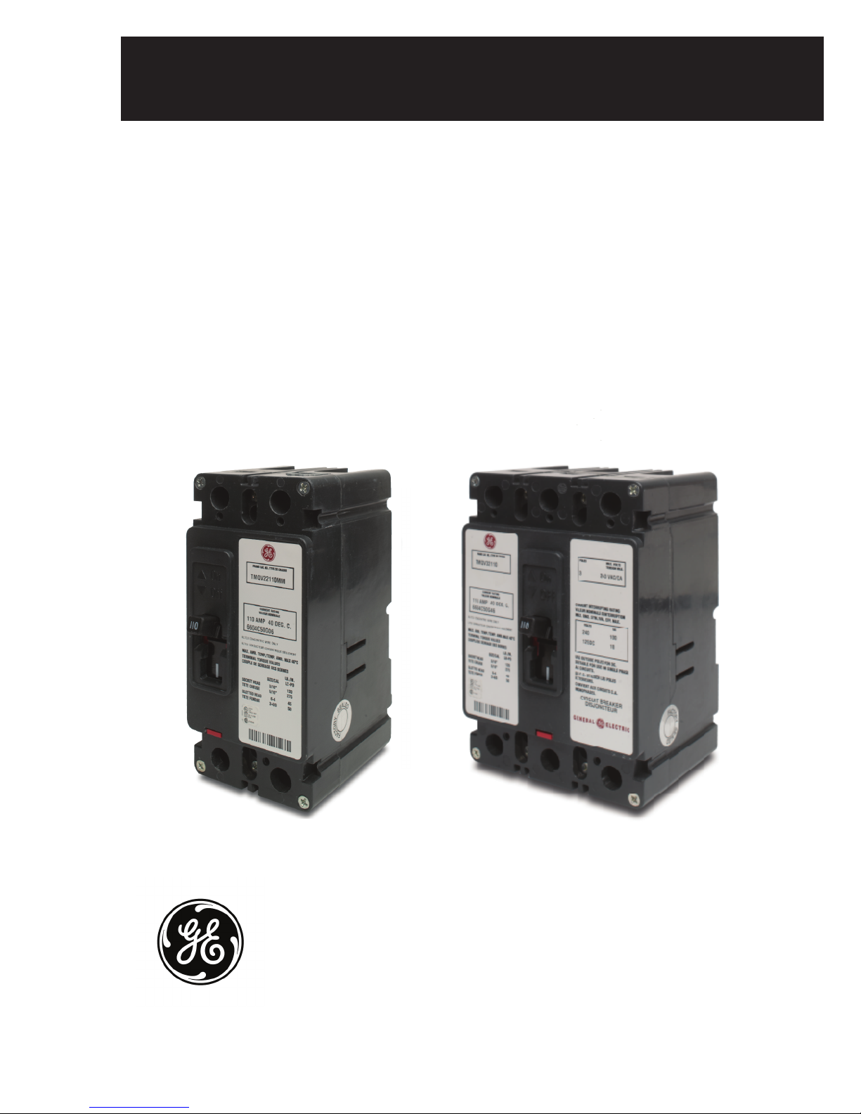
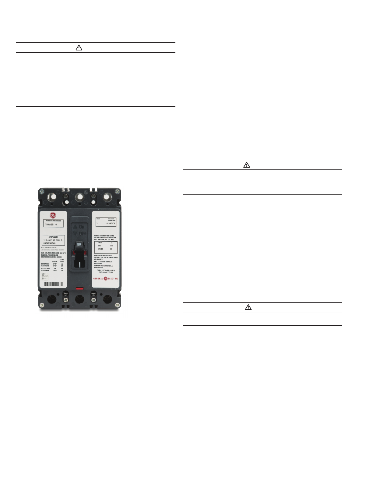
Figure 1. TMQV Circuit Breaker and Molded Case Switches
TMQV
The circuit breakers (Fig. 1) are rated from 60A to 225A continu ous current and are available as thermal-magnetic circuit breakers
and molded case switches . (Molded case switches are available rated at 225A .) Circuit breakers are listed in accordance with
Underwriters Laboratories, Inc. Standard UL489 . Molded case
switches are listed in accordance with UL489 . For this publication,
the term circuit breaker also includes molded case switches and QV
is used to cover all of the circuit breakers and molded case switches
associated with this instruction sheet..
a. For individual mounting panels, make sure that mounting panel is
predrilled using bolt drilling plan (Fig . 2). For panelboard mounting,
only load end support mounting holes are required. For deadfront
cov
er applications make sure panel cover is cut out to correct
escutcheon dimensions (Fig .3) .
CAUTION
DO NOT EXCEED CONNECTOR/BUS CAPACITY IN THE APPROVED PANEL
ASSEMBLY .
b. If circuit breaker includes factory installed internal accessories,
make sure accessory wiring can be reached when the circuit
breaker is mounted .
c. Position circuit breaker on mounting surface.
d. Install mounting screws, washers, and nuts . Tighten screws
firmly, but do not exceed 28 pound-inches (3.16 N.m)
2
 Loading...