

Page 1

May 2003
Process Control Instruments
Model TMO2D-TC
Thermal Conductivity Analyzer
User’s Manual 910-146A2
Page 2
May 2003
TMO2-TC Thermal Conductivity Transmitter with TMO2D
iii
Page 3

May 2003
Warranty Each instrument manufactured by GE Panametrics is warranted to be
free from defects in material and workmanship. Liability under this
warranty is limited to restoring the instrument to normal operation or
replacing the instrument, at the sole discretion of GE Panametrics. Fuses
and batteries are specifically excluded from any liability. This warranty
is effective from the date of delivery to the original purchaser. If GE
Panametrics determines that the equipment was defective, the warranty
period is:
• one year for general electronic failures of the instrument
• one year for mechanical failures of the transducers
If GE Panametrics determines that the equipment was damaged by
misuse, improper installation, the use of unauthorized replacement parts,
or operating conditions outside the guidelines specified by GE
Panametrics, the repairs are not covered under this warranty.
The warranties set forth herein are exclusive and are in lieu of
all other warranties whether statutory, express or implied
(including warranties or merchantability and fitness for a
particular purpose, and warranties arising from course of
dealing or usage or trade).
Return Policy If a GE Panametrics instrument malfunctions within the warranty period,
the following procedure must be completed:
1. Notify GE Panametrics, giving full details of the problem, and
provide the model number and serial number of the instrument. If the
nature of the problem indicates the need for factory service, GE
Panametrics will issue a RETURN AUTHORIZATION NUMBER
(RAN), and shipping instructions for the return of the instrument to a
service center will be provided.
2. If GE Panametrics instructs you to send your instrument to a service
center, it must be shipped prepaid to the authorized repair station
indicated in the shipping instructions.
3. Upon receipt, GE Panametrics will evaluate the instrument to
determine the cause of the malfunction.
Then, one of the following courses of action will then be taken:
• If the damage is covered under the terms of the warranty, the
instrument will be repaired at no cost to the owner and returned.
• If GE Panametrics determines that the damage is not covered under
the terms of the warranty, or if the warranty has expired, an estimate
for the cost of the repairs at standard rates will be provided. Upon
receipt of the owner’s approval to proceed, the instrument will be
repaired and returned.
iv
Page 4

May 2003
Table of Contents
Chapter 1: Features and Capabilities
Overview . . . . . . . . . . . . . . . . . . . . . . . . . . . . . . . . . . . . . . . . . . . . . . . . . . . . . . . . . . . . . . . . . . . .1-1
Introduction . . . . . . . . . . . . . . . . . . . . . . . . . . . . . . . . . . . . . . . . . . . . . . . . . . . . . . . . . . . . . . . . . .1-1
Theory of Operation . . . . . . . . . . . . . . . . . . . . . . . . . . . . . . . . . . . . . . . . . . . . . . . . . . . . . . . . . . .1-3
System Description . . . . . . . . . . . . . . . . . . . . . . . . . . . . . . . . . . . . . . . . . . . . . . . . . . . . . . . . . . . .1-5
TMO2-TC Transmitter . . . . . . . . . . . . . . . . . . . . . . . . . . . . . . . . . . . . . . . . . . . . . . . . . . . . . .1-5
Sample System . . . . . . . . . . . . . . . . . . . . . . . . . . . . . . . . . . . . . . . . . . . . . . . . . . . . . . . . . . . .1-9
TMO2D-TC Display. . . . . . . . . . . . . . . . . . . . . . . . . . . . . . . . . . . . . . . . . . . . . . . . . . . . . . . .1-9
Extra Cable (optional). . . . . . . . . . . . . . . . . . . . . . . . . . . . . . . . . . . . . . . . . . . . . . . . . . . . . . .1-9
Typical Applications . . . . . . . . . . . . . . . . . . . . . . . . . . . . . . . . . . . . . . . . . . . . . . . . . . . . . . . . . .1-10
Chapter 2: Installation
Overview . . . . . . . . . . . . . . . . . . . . . . . . . . . . . . . . . . . . . . . . . . . . . . . . . . . . . . . . . . . . . . . . . . . .2-1
Introduction . . . . . . . . . . . . . . . . . . . . . . . . . . . . . . . . . . . . . . . . . . . . . . . . . . . . . . . . . . . . . . . . . .2-2
Mounting the TMO2-TC Transmitter . . . . . . . . . . . . . . . . . . . . . . . . . . . . . . . . . . . . . . . . . . . . . .2-2
Mounting the Sample System . . . . . . . . . . . . . . . . . . . . . . . . . . . . . . . . . . . . . . . . . . . . . . . . . . . .2-3
Manual, 2-Port (Sealed Reference Gas) Sample System . . . . . . . . . . . . . . . . . . . . . . . . . . . .2-3
Manual, 4-Port (Flowing Reference Gas) Sample System . . . . . . . . . . . . . . . . . . . . . . . . . . .2-4
Automatic, 2-Port (Sealed Reference Gas) Sample System . . . . . . . . . . . . . . . . . . . . . . . . . .2-5
Mounting the TMO2D-TC Display. . . . . . . . . . . . . . . . . . . . . . . . . . . . . . . . . . . . . . . . . . . . . . . .2-6
Wiring the TMO2-TC Transmitter . . . . . . . . . . . . . . . . . . . . . . . . . . . . . . . . . . . . . . . . . . . . . . . .2-7
Wiring the TMO2D-TC Display . . . . . . . . . . . . . . . . . . . . . . . . . . . . . . . . . . . . . . . . . . . . . . . . .2-12
Chapter 3: Operation
Overview . . . . . . . . . . . . . . . . . . . . . . . . . . . . . . . . . . . . . . . . . . . . . . . . . . . . . . . . . . . . . . . . . . . .3-1
Introduction . . . . . . . . . . . . . . . . . . . . . . . . . . . . . . . . . . . . . . . . . . . . . . . . . . . . . . . . . . . . . . . . . .3-1
Powering Up the TMO2D-TC Analyzer . . . . . . . . . . . . . . . . . . . . . . . . . . . . . . . . . . . . . . . . . . . .3-1
Establishing a Flow of Sample Gas. . . . . . . . . . . . . . . . . . . . . . . . . . . . . . . . . . . . . . . . . . . . . . . .3-2
Operating the TMO2D-TC Display. . . . . . . . . . . . . . . . . . . . . . . . . . . . . . . . . . . . . . . . . . . . . . . .3-3
LCD Display . . . . . . . . . . . . . . . . . . . . . . . . . . . . . . . . . . . . . . . . . . . . . . . . . . . . . . . . . . . . . .3-3
Keypad . . . . . . . . . . . . . . . . . . . . . . . . . . . . . . . . . . . . . . . . . . . . . . . . . . . . . . . . . . . . . . . . . .3-3
Chapter 4: Programming
Overview . . . . . . . . . . . . . . . . . . . . . . . . . . . . . . . . . . . . . . . . . . . . . . . . . . . . . . . . . . . . . . . . . . . .4-1
Introduction . . . . . . . . . . . . . . . . . . . . . . . . . . . . . . . . . . . . . . . . . . . . . . . . . . . . . . . . . . . . . . . . . .4-2
Key Functions . . . . . . . . . . . . . . . . . . . . . . . . . . . . . . . . . . . . . . . . . . . . . . . . . . . . . . . . . . . . . . . .4-3
Entering Programming Mode . . . . . . . . . . . . . . . . . . . . . . . . . . . . . . . . . . . . . . . . . . . . . . . . . . . .4-5
Menu Navigation . . . . . . . . . . . . . . . . . . . . . . . . . . . . . . . . . . . . . . . . . . . . . . . . . . . . . . . . . . . . . .4-5
The Main Menu . . . . . . . . . . . . . . . . . . . . . . . . . . . . . . . . . . . . . . . . . . . . . . . . . . . . . . . . . . . . . . .4-6
The Setup Menu . . . . . . . . . . . . . . . . . . . . . . . . . . . . . . . . . . . . . . . . . . . . . . . . . . . . . . . . . . .4-6
The Recorders Menu. . . . . . . . . . . . . . . . . . . . . . . . . . . . . . . . . . . . . . . . . . . . . . . . . . . . . . .4-13
The Alarms Menu . . . . . . . . . . . . . . . . . . . . . . . . . . . . . . . . . . . . . . . . . . . . . . . . . . . . . . . . .4-15
The Tests Menu. . . . . . . . . . . . . . . . . . . . . . . . . . . . . . . . . . . . . . . . . . . . . . . . . . . . . . . . . . .4-16
The Calibration Menu . . . . . . . . . . . . . . . . . . . . . . . . . . . . . . . . . . . . . . . . . . . . . . . . . . . . . .4-19
v
Page 5

May 2003
Table of Contents (cont.)
Chapter 5: Calibration
Overview . . . . . . . . . . . . . . . . . . . . . . . . . . . . . . . . . . . . . . . . . . . . . . . . . . . . . . . . . . . . . . . . . . . 5-1
Introduction . . . . . . . . . . . . . . . . . . . . . . . . . . . . . . . . . . . . . . . . . . . . . . . . . . . . . . . . . . . . . . . . . 5-1
Required Equipment and Materials . . . . . . . . . . . . . . . . . . . . . . . . . . . . . . . . . . . . . . . . . . . . . . . 5-3
Preparing the Transmitter for Calibration . . . . . . . . . . . . . . . . . . . . . . . . . . . . . . . . . . . . . . . . . . 5-4
2-Port (Sealed Reference Gas) Calibration . . . . . . . . . . . . . . . . . . . . . . . . . . . . . . . . . . . . . . . . . 5-6
4-Port (Flowing Reference Gas) Calibration . . . . . . . . . . . . . . . . . . . . . . . . . . . . . . . . . . . . . . . . 5-8
Checking/Changing Switch and Jumper Settings . . . . . . . . . . . . . . . . . . . . . . . . . . . . . . . . . . . . 5-9
Chapter 6: Specifications
TMO2-TC Transmitter Specifications . . . . . . . . . . . . . . . . . . . . . . . . . . . . . . . . . . . . . . . . . . . . . 6-1
Performance. . . . . . . . . . . . . . . . . . . . . . . . . . . . . . . . . . . . . . . . . . . . . . . . . . . . . . . . . . . . . . 6-1
Functional . . . . . . . . . . . . . . . . . . . . . . . . . . . . . . . . . . . . . . . . . . . . . . . . . . . . . . . . . . . . . . . 6-2
Physical . . . . . . . . . . . . . . . . . . . . . . . . . . . . . . . . . . . . . . . . . . . . . . . . . . . . . . . . . . . . . . . . . 6-2
Accessories . . . . . . . . . . . . . . . . . . . . . . . . . . . . . . . . . . . . . . . . . . . . . . . . . . . . . . . . . . . . . . 6-2
TMO2D-TC Display Specifications . . . . . . . . . . . . . . . . . . . . . . . . . . . . . . . . . . . . . . . . . . . . . . 6-3
Performance. . . . . . . . . . . . . . . . . . . . . . . . . . . . . . . . . . . . . . . . . . . . . . . . . . . . . . . . . . . . . . 6-3
Functional . . . . . . . . . . . . . . . . . . . . . . . . . . . . . . . . . . . . . . . . . . . . . . . . . . . . . . . . . . . . . . . 6-3
Physical . . . . . . . . . . . . . . . . . . . . . . . . . . . . . . . . . . . . . . . . . . . . . . . . . . . . . . . . . . . . . . . . . 6-4
Chapter 7: Ordering Information
Appendix A: Relative Thermal Conductivity of Common Gases
Appendix B: Applications
H2 in N2 in Heat Treat Furnace Atmospheres. . . . . . . . . . . . . . . . . . . . . . . . . . . . . . . . . . . . . . . B-1
Problem . . . . . . . . . . . . . . . . . . . . . . . . . . . . . . . . . . . . . . . . . . . . . . . . . . . . . . . . . . . . . . . . . B-1
Equipment . . . . . . . . . . . . . . . . . . . . . . . . . . . . . . . . . . . . . . . . . . . . . . . . . . . . . . . . . . . . . . . B-1
Basic Operating Procedure . . . . . . . . . . . . . . . . . . . . . . . . . . . . . . . . . . . . . . . . . . . . . . . . . . B-2
Permanent Installation . . . . . . . . . . . . . . . . . . . . . . . . . . . . . . . . . . . . . . . . . . . . . . . . . . . . . . B-4
Specifications. . . . . . . . . . . . . . . . . . . . . . . . . . . . . . . . . . . . . . . . . . . . . . . . . . . . . . . . . . . . . B-4
Detailed Operating Procedure . . . . . . . . . . . . . . . . . . . . . . . . . . . . . . . . . . . . . . . . . . . . . . . . B-4
H2 Purity in H2 Electricity Generator Cooling . . . . . . . . . . . . . . . . . . . . . . . . . . . . . . . . . . . . . . B-7
Problem . . . . . . . . . . . . . . . . . . . . . . . . . . . . . . . . . . . . . . . . . . . . . . . . . . . . . . . . . . . . . . . . . B-7
Equipment . . . . . . . . . . . . . . . . . . . . . . . . . . . . . . . . . . . . . . . . . . . . . . . . . . . . . . . . . . . . . . . B-7
Basic Operating Procedure . . . . . . . . . . . . . . . . . . . . . . . . . . . . . . . . . . . . . . . . . . . . . . . . . . B-8
How Previously Handled. . . . . . . . . . . . . . . . . . . . . . . . . . . . . . . . . . . . . . . . . . . . . . . . . . . B-10
Permanent Installation . . . . . . . . . . . . . . . . . . . . . . . . . . . . . . . . . . . . . . . . . . . . . . . . . . . . . B-10
Specifications. . . . . . . . . . . . . . . . . . . . . . . . . . . . . . . . . . . . . . . . . . . . . . . . . . . . . . . . . . . . B-10
Detailed Operating Procedure . . . . . . . . . . . . . . . . . . . . . . . . . . . . . . . . . . . . . . . . . . . . . . . B-10
vi
Page 6

May 2003
Table of Contents (cont.)
Appendix C: Installation and Maintenance Drawings
Appendix D: Menu Flow Diagrams
Appendix E: Special Programming
Overview . . . . . . . . . . . . . . . . . . . . . . . . . . . . . . . . . . . . . . . . . . . . . . . . . . . . . . . . . . . . . . . . . . . E-1
Entering the Hidden Menu . . . . . . . . . . . . . . . . . . . . . . . . . . . . . . . . . . . . . . . . . . . . . . . . . . . . . E-1
Select Gas . . . . . . . . . . . . . . . . . . . . . . . . . . . . . . . . . . . . . . . . . . . . . . . . . . . . . . . . . . . . . . . E-2
LabCal Recorders . . . . . . . . . . . . . . . . . . . . . . . . . . . . . . . . . . . . . . . . . . . . . . . . . . . . . . . . . E-3
Manual Offset . . . . . . . . . . . . . . . . . . . . . . . . . . . . . . . . . . . . . . . . . . . . . . . . . . . . . . . . . . . . E-4
Erase RAM . . . . . . . . . . . . . . . . . . . . . . . . . . . . . . . . . . . . . . . . . . . . . . . . . . . . . . . . . . . . . . . . . E-5
Appendix F: Calibration Procedure and Adjustment Locations for Older Versions
Calibration Procedure for PCB #703-1036 . . . . . . . . . . . . . . . . . . . . . . . . . . . . . . . . . . . . . . . . . .F-1
2-Port (Sealed Reference Gas) Calibration. . . . . . . . . . . . . . . . . . . . . . . . . . . . . . . . . . . . . . .F-1
4-Port (Flowing Reference Gas) Calibration . . . . . . . . . . . . . . . . . . . . . . . . . . . . . . . . . . . . .F-4
Checking/Changing Switch and Jumper Settings. . . . . . . . . . . . . . . . . . . . . . . . . . . . . . . . . .F-6
Calibration Procedure for PCB #703-867 . . . . . . . . . . . . . . . . . . . . . . . . . . . . . . . . . . . . . . . . . . .F-7
2-Port (Sealed Reference Gas) Calibration. . . . . . . . . . . . . . . . . . . . . . . . . . . . . . . . . . . . . . .F-7
4-Port (Flowing Reference Gas) Calibration . . . . . . . . . . . . . . . . . . . . . . . . . . . . . . . . . . . . .F-9
Appendix G: Sample TMO2D-TC Calibration Sheet
Appendix H: Installation Instructions for CE Mark Compliance
Installation Instructions for CE Mark Compliance . . . . . . . . . . . . . . . . . . . . . . . . . . . . . . . . . . . H-1
vii
Page 7

Chapter 1
Page 8

Features and Capabilities
Overview . . . . . . . . . . . . . . . . . . . . . . . . . . . . . . . . . . . . . . . . . . . . . .1-1
Introduction . . . . . . . . . . . . . . . . . . . . . . . . . . . . . . . . . . . . . . . . . . .1-1
Theory of Operation. . . . . . . . . . . . . . . . . . . . . . . . . . . . . . . . . . . . . 1-3
System Description . . . . . . . . . . . . . . . . . . . . . . . . . . . . . . . . . . . . .1-5
Typical Applications. . . . . . . . . . . . . . . . . . . . . . . . . . . . . . . . . . . .1-10
Page 9

May 2003
Overview This chapter will introduce you to the features and capabilities of the
GE Panametrics TMO2D-TC Thermal Conductivity Analyzer. You
will find the following topics discussed:
• Introduction — A discussion of the TMO2D-TC Analyzer features
and capabilities.
• Theory of Operation — Details on TMO2-TC Transmitter
construction and how the measurement is made.
• System Description — A detailed description of the basic
TMO2D-TC Analyzer and available options, and sample systems.
• Typical Applications — A brief discussion of industries and
applications where the TMO2D-TC can be used, along with two
common applications and the required TMO2D-TC
configurations.
TMO2D-TC technical specifications can be found in Chapter 6,
Specifications. Ordering information can be found in Chapter 7,
Ordering Information.
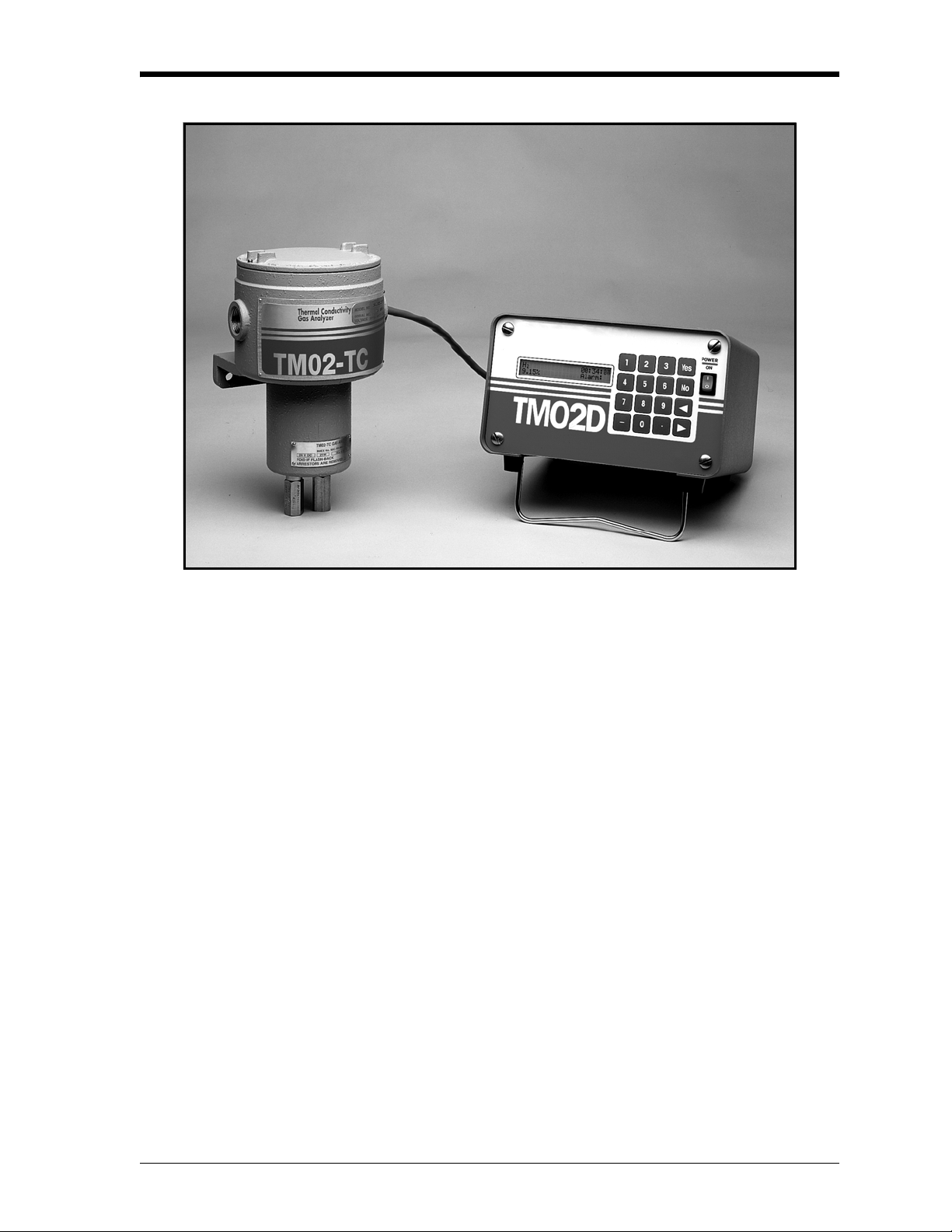
Introduction The GE Panametrics TMO2D-TC is an analyzer that measures the
thermal conductivity of a binary (or pseudo-binary) gas mixture,
determines and displays the concentration of one of the gases in the
mixture, and also provides 0/4-20 mA and RS232C outputs and alarm
relays for process control requirements. The TMO2D-TC consists of
two main components — the TMO2-TC Transmitter and the
TMO2D-TC Display.
The TMO2-TC Transmitter offers several unique design features:
• Ultra-stable thermistors and a temperature-controlled measuring
cell (55
span stability, as well as insensitivity to ambient temperature
variations.
o
C standard, or 70 oC optional) provide excellent zero and
• The measuring cell design makes it resistant to contamination and
essentially flow insensitive. Since it has no moving parts, the
transmitter can handle the shock and vibration found in many
industrial applications.
• You can select a 2-port version for measurement of zero-based gas
mixtures using a sealed reference gas (air), or 4-port version for
measurement of zero-suppressed gas mixtures (and some other
special calibrations) using a flowing reference gas.
Features and Capabilities 1-1
Page 10

11/1/95
Introduction (cont.) • The TMO2-TC modular construction means that the unit can be
field-calibrated quickly and easily; or the plug-in measuring cell
can be replaced with a pre-calibrated spare in minutes.
• The TMO2-TC Transmitter, with weatherproof and explosion-
proof packaging, is designed to be installed as close as possible to
the process sample point. It can be located up to 2,800 feet (850
meters) from the TMO2D-TC Display using inexpensive,
unshielded cable.
The TMO2D-TC Display offers several advanced features:
• The microprocessor-based TMO2D-TC electronics unit features a
two-line, backlit LCD display, full keypad, and menu-driven
software to provide easy access to a variety of features, including
user-selectable gas range, recorder output range, alarm settings,
and automatic calibration (Auto Cal).
• Standard 0/4-20 mA output and dual Form C alarm relays, coupled
with optional dual isolated 0/4-20 mA outputs and dual relays for
Auto Cal, provide excellent flexibility for process control
applications.
• Long-term, hands-off performance is provided by Auto Cal. When
re calibration is desired, the TMO2D-TC controls solenoid valves
in the sample system to bring zero and span gases to the TMO2-TC
Transmitter. Then, TMO2D-TC software compares the Auto Cal
readings with factory calibration data and makes any necessary
corrections -automatically - so manual re calibration requirements
can be reduced significantly.
• The TMO2D-TC Display, with bench, rack, panel, weatherproof,
and explosion-proof packaging options, can be located adjacent to
the TMO2-TC Transmitter, or up to 2,800 feet (850 meters) away
using inexpensive, unshielded cable.
1-2 Features and Capabilities
Page 11

11/1/95
Theory of Operation The TMO2-TC Transmitter measures the concentration of a gas in a
binary gas mixture by measuring the thermal conductivity of the
sample gas and comparing it to the thermal conductivity of a selected
reference gas.
Two ultra-stable, glass-coated thermistors are used: one in contact
with the sample gas, and the other in contact with a selected reference
gas. The thermistors are mounted so that they are in close proximity
to the stainless steel walls of the sample chamber. The entire sensor is
o
heated to 55
sensor temperature using a constant current source. The thermistors
lose heat to the walls of the sample chamber at a rate that is
proportional to the thermal conductivity of the gas surrounding them.
Thus, each thermistor will reach a different equilibrium temperature.
The temperature difference between the two thermistors is detected in
an electrical bridge circuit. It is amplified and converted to a 4-20 mA
output proportional to the concentration of one of the constituents of
the binary gas mixture.
C (or 70 oC) and the thermistors are heated above the
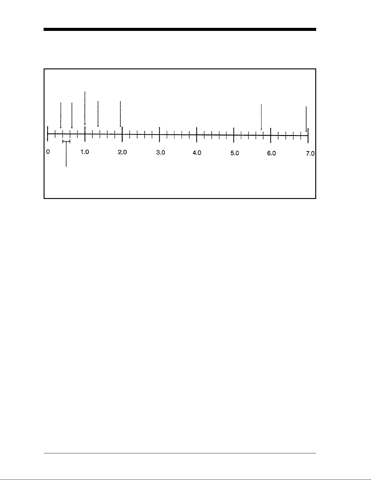
Appendix A contains a Table of Relative Thermal Conductivity of
Common Gases. Figure 1-1 on the next page shows several of these
values graphically. In order to measure 0 to 25% H
in N2, the
2
reference gas would be air (2-port version, sealed reference gas), and,
for calibration, the zero gas would be 100% N
span gas 25% H
, the reference gas would be 100% H2 (4-port version, flowing
N
2
(balance N2). In order to measure 90-100% H2 in
2
reference gas), the zero gas would be 90% H
span gas 100% H
(the same as the reference gas).
2
(i.e., 0 % H2) and the
2
(balance N2), and the
2
The TMO2-TC has a polarity adjustment switch which permits the
measurement of gases (such as CO
) with relative thermal
2
conductivity less than the background gas.
Features and Capabilities 1-3
Page 12
11/1/95
Theory of Operation
(cont.)
Air/N
2
SO
CO
2
C4-C
6
2
CH4Ne
He
H
2
Figure 1-1: Relative Thermal Conductivity of Several Common Gases
1-4 Features and Capabilities
Page 13

May 2003
System Description The basic TMO2D-TC measurement system consists of a TMO2-TC
Transmitter mounted in a sample system and connected to a TMO2DTC Display. The sample system is mandatory, and can be provided by
GE Panametrics or constructed according to our recommendations.
The TMO2D-TC is supplied with a standard 10 ft. (3 m), 3-wire cable
for connecting the transmitter to the display module. Lengths up to
2,800 ft. (850 m) are optionally available.
TMO2-TC Transmitter The TMO2-TC Transmitter is self-contained, consisting of the
thermal conductivity sensor and associated electronics. It requires 24
VDC power (1 amp maximum at power-up), which it receives from
the TMO2D-TC Display. It provides a 4-20 mA output signal to the
display module proportional to the thermal conductivity of the sample
gas and to the concentration of one of the gases in the binary mixture.
The TMO2-TC is designed to be installed in a sample system as close
as possible to the process sample point. Thus, it is available in two
environmental packages — weatherproof (NEMA-4X; IP65) and
explosion-proof (Class I, Groups C,D, Div. 1; Cenelec EEx d II C T6)
with the addition of flame arrestors to the sample/reference gas inlet
and outlet.
Each environmental package is available in a standard 2-port (sealed
reference gas) version, or optional 4-port (flowing reference gas)
version.
Features and Capabilities 1-5
Page 14
11/1/95
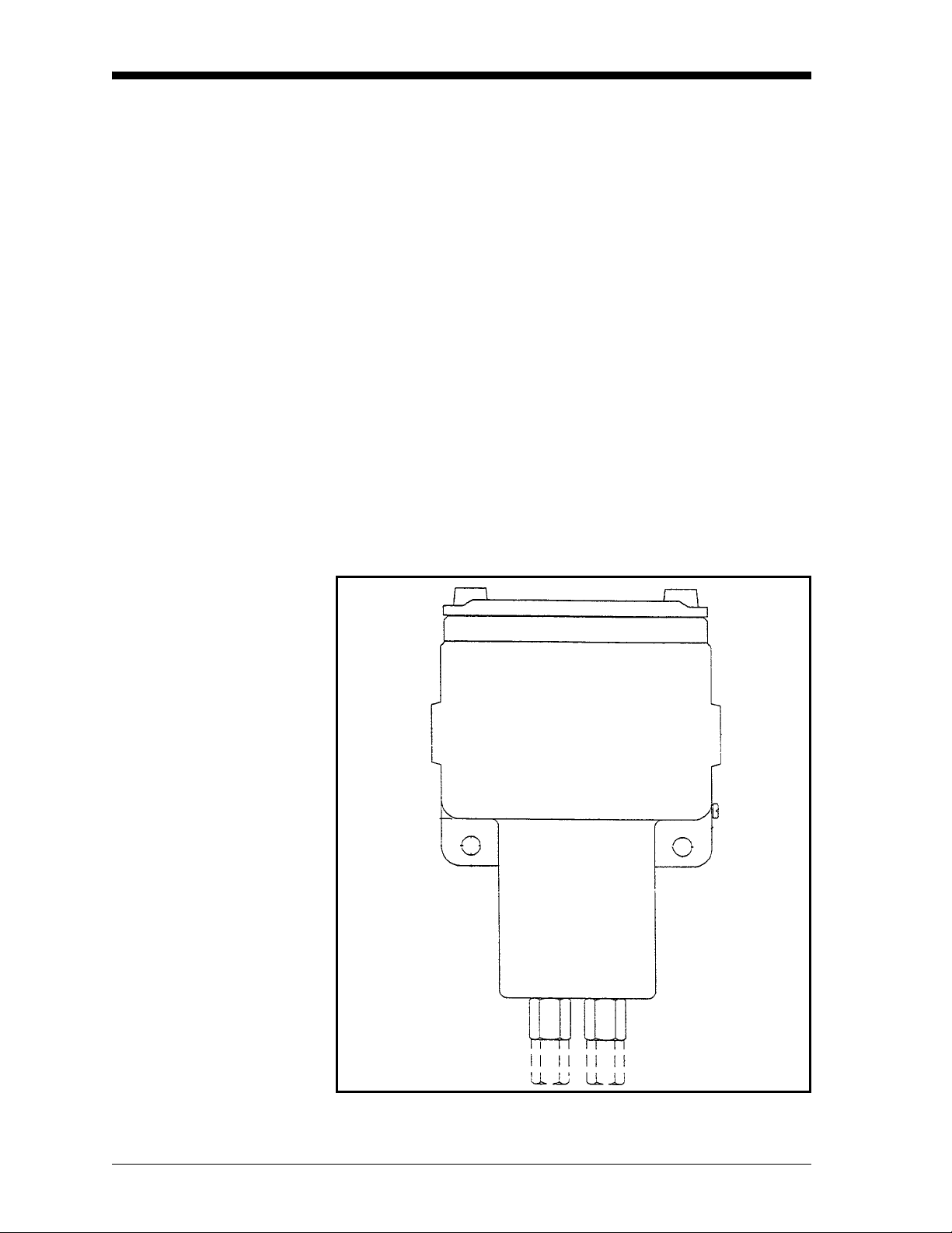
2-Port (Sealed Reference Gas) Version
This standard configuration (see Figure 1-2 below) is used for zerobased ranges with air or nitrogen at atmospheric pressure as the
balance or background gas. It utilizes air with desiccant in a factorysealed chamber as the reference gas. The following standard ranges
and gases are provided:
0 to 1%
0 to 2%
0 to 5%
0 to 10%
0 to 25%
0 to 50%
0 to 100%
in N
H
2
2
CO2 in N2 (minimum range 0 to 5% CO2)|
in Air (minimum range 0 to 5% CO2)
CO
2
He in N
He in Air
2
Figure 1-2: 2-Port (Sealed Reference Gas) TMO2-TC
1-6 Features and Capabilities
Page 15

11/1/95
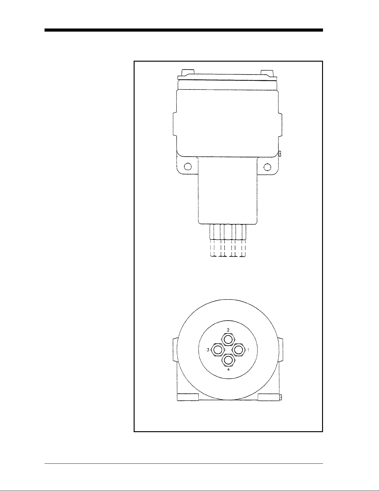
4-Port (Flowing Reference Gas) Version
This optional configuration (see Figure 1-3 on the following page) is
used for zero-suppressed ranges and some other special applications.
Typically, a flowing reference gas of 100% H
following standard ranges and gases are provided:
90 to 100%
80 to 100%
in N
H
2
2
CO2 in N2/Air
He in N
2
/Air
Note: For factory calibration pricing on the standard ranges and
gases, or for pricing on other zero-suppressed ranges and
gases, please consult the factory.
The TMO2-TC is supplied with a standard measurement cell
o
operating temperature of 55
C. An optional 70 oC cell operating
temperature is available.
or CO2 is used. The
2
Note: The 70
high temperature applications, since it will result in reduced
sensitivity.
o
C operating temperature should be selected only for
Features and Capabilities 1-7
Page 16
11/1/95
4-Port (Flowing Reference Gas) Version (cont.)
Top View
Bottom View
Figure 1-3: 4-Port (Flowing Reference Gas) TMO2-TC
1-8 Features and Capabilities
Page 17

May 2003
Sample System A sample system is mandatory for use with the TMO2-TC. The
design of the sample system will depend on the conditions of the
sample gas and the requirements of the application. In general, a
sample system must deliver a clean, representative sample to the
TMO2-TC at a temperature, pressure, and flow rate that are within
acceptable limits. Standard TMO2-TC sample conditions are as
follows:
• Less than 50
temperature)
o
C (122 oF) temperature (for 55 oC cell operating
• Atmospheric pressure
• 0.5 SCFH (250 cc/min) flow rate
GE Panametrics offers sample systems for a wide variety of
applications. Three standard sample systems for the TMO2-TC are
shown in Chapter 2, Installation. For assistance in designing your
own sample system, please consult the factory.
TMO2D-TC Display The TMO2D-TC Display receives a 4-20 mA signal from the TMO2-
TC Transmitter proportional to the concentration of one of the gases
in the binary mixture (the sample gas). It then displays the
concentration (and other information) on a 2-line x 24 character,
backlit LCD.
It requires 100/120/220/240 VAC power (35 watts max.), and
provides 24 VDC power to the TMO2-TC Transmitter. The standard
TMO2D-TC provides a 0/4-20 mA analog output; an RS232C digital
output; and dual Form C, SPDT relays for process monitoring and
control. Dual isolated 0/4-20 mA outputs and a second pair of relays
for Auto Cal are available as options.
The TMO2D-TC can be located adjacent to the TMO2-TC
Transmitter or as far as 2,800 ft. (850 m) away. It is provided in
bench, rack, panel, weatherproof (NEMA 4X; IP65), or explosionproof mounting configurations. The standard TMO2D-TC is suitable
for use in general purpose areas. A package suitable for use in Class I,
Div. 2 hazardous areas is available as an option. This package
includes hermetically-sealed alarm relays.
Extra Cable (optional) GE Panametrics provides a 10 ft. (3 m) length of 3-wire, color-coded
cable with each TMO2D-TC to connect the transmitter to the display
module. The same cable is available in lengths up to 2,800 ft (850 m).
If you are using your own cable, refer to Chapter 2, Table 2-2, Cable
Requirements, for recommendations.
Features and Capabilities 1-9
Page 18

11/1/95
Typical Applications The TMO2D-TC can be used in a wide variety of industrial
applications where it is necessary to measure the concentration of one
component of a binary gas mixture. It can also be used in pseudobinary gas mixtures where the ratio of concentrations of the
background gas components remains constant, and in gaseous
mixtures where the thermal conductivity of the gas of interest is
significantly different from that of the background gas. Some typical
industries and applications include:
• Metals Industry —
H
in heat treat furnace atmospheres
2
• Electric Power Industry —
in generator cooling systems
H
2
• Gas Production Industry —
Purity monitoring of argon, hydrogen, nitrogen, helium
• Chemical Industry —
in ammonia synthesis gas
H
2
H
in methanol synthesis gas
2
in chlorine plants
H
2
• Food Industry —
CO
in fermentation processes
2
Ethylene Oxide (ETO) sterilization
• Steel Industry —
in blast furnace top gas
H
2
• Petroleum Industry —
in hydrocarbon streams
H
2
Two very common applications are as follows:
in N2 in heat treat furnace atmospheres - Zero-based 0-25%
1. H
2
, 2-Port (sealed reference gas, air)
H
2
purity in H2 electricity generator cooling - Zero-suppressed,
2. H
2
80-100% H
For more details on these applications, refer to Appendix B,
Applications. For details on applications not shown in Appendix B, or
if you wish to discuss your own application, please consult the
factory.
, 4-Port (flowing reference gas, 100% H2)
2
1-10 Features and Capabilities
Page 19

Chapter 2
Page 20

Installation
Overview . . . . . . . . . . . . . . . . . . . . . . . . . . . . . . . . . . . . . . . . . . . . . .2-1
Introduction . . . . . . . . . . . . . . . . . . . . . . . . . . . . . . . . . . . . . . . . . . .2-2
Mounting the TMO2-TC Transmitter . . . . . . . . . . . . . . . . . . . . . . . .2-2
Mounting the Sample System . . . . . . . . . . . . . . . . . . . . . . . . . . . . .2-3
Mounting the TMO2D-TC Display . . . . . . . . . . . . . . . . . . . . . . . . . .2-6
Wiring the TMO2-TC Transmitter . . . . . . . . . . . . . . . . . . . . . . . . . .2-7
Wiring the TMO2D-TC Display . . . . . . . . . . . . . . . . . . . . . . . . . . .2-12
Page 21

May 2003
Overview This chapter will describe how to mount and wire the TMO2-TC
Transmitter and its sample system, and the TMO2D-TC Display. You
will find the following topics discussed:
• Introduction — A brief discussion of installation steps.
• Mounting the TMO2-TC Transmitter — How to mount the
transmitter in a sample system.
• Mounting the Sample System — Mounting and plumbing a GE
Panametrics sample system. Includes drawings of basic 2-Port and
4-Port sample systems, and an automatic 2-Port sample system.
• Mounting the TMO2D-TC Display — How to mount the different
TMO2D-TC packaging configurations.
• Wiring the TMO2-TC Transmitter — How to connect the
transmitter to the display module.
• Wiring the TMO2D-TC Display — Connecting 100/120/220/240
VAC power, 0/4-20 mA output and alarm relay wiring to the
TMO2D-TC.
!WARNING!
TO ENSURE THE SAFE OPERATION OF THE
TMO2D-TC, YOU MUST INSTALL AND OPERATE IT
AS DESCRIBED IN THIS MANUAL. IN ADDITION, BE
SURE TO FOLLOW ALL APPLICABLE SAFETY
CODES AND REGULATIONS FOR INSTALLING
ELECTRICAL EQUIPMENT IN YOUR AREA.
PROCEDURES SHOULD BE PERFORMED BY
TRAINED SERVICE PERSONNEL.
!ATTENTION EUROPEAN CUSTOMERS!
IN ORDER TO MEET CE MARK REQUIREMENTS,
YOU MUST INSTALL CABLES AS DESCRIBED IN
APPENDIX H.
Note: Different versions of the TMO2D-TC display have different
PC boards. In Appendix C refer to the appropriate drawings,
as follows:
• Serial numbers 101 through 749, schematic 700-997 and
PCB assembly drawing 703-997.
• Serial numbers 750 or greater, schematics 700-1226 and
PCB assembly drawing 703-1226.
Installation 2-1
Page 22

May 2003
Introduction Installation of the TMO2D-TC analyzer typically consists of five
steps:
1. Mounting the TMO2-TC Transmitter in a sample system. (If you
purchased your sample system from GE Panametrics, this step has
already been done for you.)
2. Mounting, plumbing (and possibly wiring) the sample system.
3. Mounting the TMO2D-TC Display.
4. Making wiring connections between the transmitter and the
display module.
5. Making wiring connections to the TMO2D-TC Display for power,
outputs, and alarms.
Mounting the TMO2-TC Transmitter
This section applies only if you are mounting the TMO2-TC
Transmitter to a sample system that has not been supplied by GE
Panametrics.
Your sample system should deliver a clean, representative sample to
the TMO2-TC at the proper temperature, pressure and flow rate. This
usually means a clean, dry sample (free of solid and liquid
particulates) at atmospheric pressure; a temperature no greater than
o
C (122 oF); and a flow rate of approximately 0.5 SCFH (250 cc/
50
min). Factory calibration of the sensor is at atmospheric pressure and
0.5 SCFH - higher or lower operating pressures may necessitate field-
calibration adjustment.
A simple sample system for a 2-Port TMO2-TC might have an inlet
and/or outlet flow regulating needle valve; a flow meter; and a
pressure gauge, in addition to the TMO2-TC Transmitter.
The TMO2-TC Transmitter should be mounted in the sample system
o
so that it is upright and level to within +/- 15
. Also, provide at least
9" of clearance above the top cover of the transmitter to allow access
to the transmitter printed circuit board (PCB) for calibration and
maintenance. For a 2-Port TMO2-TC, connect the sample system
Sample Inlet and Sample Outlet portions to the appropriate TMO2TC port (see Drawing 712-225 in Appendix C for port location). For a
4-Port system, also connect the Reference Inlet and Reference Outlet
portions to the appropriate TMO2-TC port (see Drawing 712-226 in
Appendix C for port location).
!WARNING!
FOR EXPLOSION-PROOF UNITS, BE SURE TO
CONFORM TO ALL SAFETY AND ELECTRICAL
CODE REQUIREMENTS.
2-2 Installation
Page 23
May 2003
Mounting the Sample System
Manual, 2-Port (Sealed Reference Gas) Sample System
You can order a complete sample system, which includes the TMO2TC Transmitter and all necessary components and sample tubing
mounted on a metal panel, from GE Panametrics. Several standard
sample systems are available; and custom-designed sample systems
can be built to your exact specifications. Following are descriptions
of three standard sample systems:
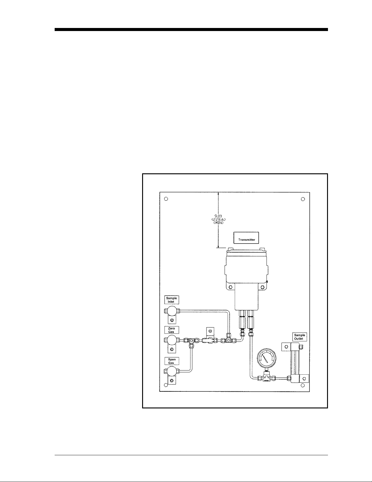
Figure 2-1 below shows a basic sample system for a 2-Port (sealed
reference gas) TMO2-TC. This sample system consists of inlet needle
valves for sample, zero, and span gases; a ball valve; a 2-port TMO2TC; a pressure gauge; and a flow meter. All components are mounted
on a painted steel plate. Other components could be added for
filtration (filter/coalescer), pressure control (regulator), or flow
control (pump).
Figure 2-1: Basic Sample System for a 2-Port TMO2-TC
Installation 2-3
Page 24
May 2003
Manual, 4-Port (Flowing Reference Gas) Sample System
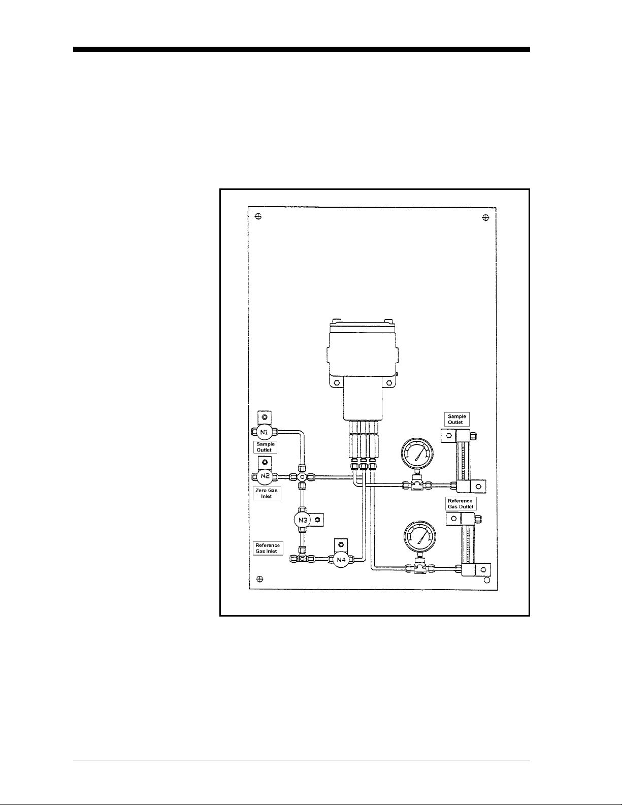
Figure 2-2 below shows a basic sample system for a 4-Port (flowing
reference gas) TMO2-TC. This sample system consists of inlet needle
valves for sample, reference, and calibration gases; a 4-port TMO2TC; two pressure gauges; and two flow meters. All components are
mounted on a painted steel plate. Other components could be added
for filtration (filter/coalescer), pressure control (regulator), or flow
control (pump).
Figure 2-2: Basic Sample System for a 4-Port TMO2-TC
2-4 Installation
Page 25
11/1/95
Automatic, 2-Port (Sealed Reference Gas) Sample System
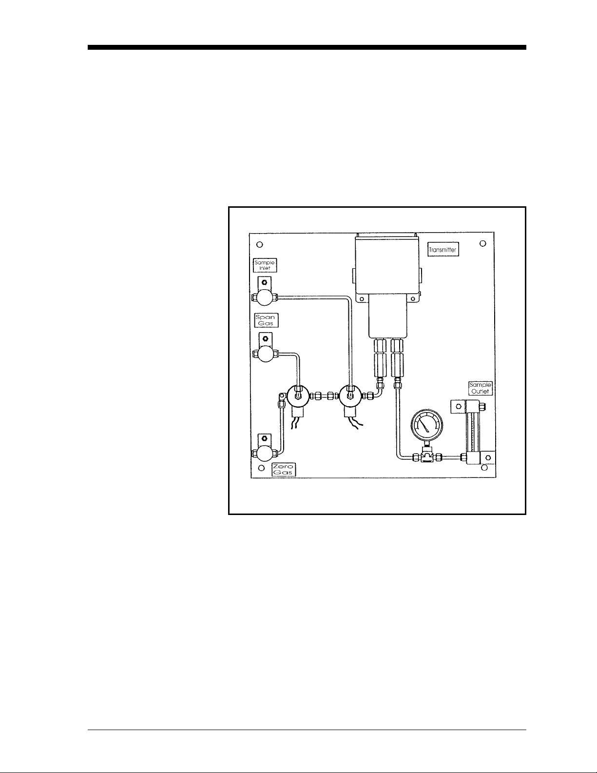
Figure 2-3 below shows an automatic sample system for a 2-Port
(sealed reference gas) TMO2-TC. This sample system requires the
Auto Cal option on the TMO2D-TC Display. It consists of inlet
needle valves for sample, zero, span, and optional calibration gases;
two electrically-actuated solenoid valves for gas selection; a 2-Port
TMO2-TC; a pressure gauge; a flowmeter; a regulating needle valve;
and a sample pump. All components are mounted on a painted steel
plate. Other components could be added for filtration (filter/
coalescer), or pressure control (regulator).
Figure 2-3: Automatic Sample System
for a 2-Port TMO2-TC
Installation 2-5
Page 26

May 2003
Automatic, 2-Port
(Sealed Reference Gas)
Sample System (cont.)
Mounting the TMO2DTC Display
When used in conjunction with the TMO2D-TC Display with the
Auto Cal option, the above sample system allows automatic
switching of sample, zero, and span gases during calibration. Refer to
Appendix B, Applications, for details on sample systems designed by
GE Panametrics for specific applications.
Mount the sample system as close as possible to the process sample
point. Once the sample system is mounted, connect all inlet and outlet
lines via the fittings on the sample system (1/4" compression). The
sample line leading from the process to the sample system should be
of 1/4" stainless steel tubing, and as short as possible in order to
insure a representative sample.
The TMO2D-TC Display is available in five mounting
configurations: bench, rack, panel, weatherproof, and explosionproof. See Appendix C, Outline and Installation Drawings, for
dimensional drawings for each configuration, as well as rack/panel
cutout dimensions.
No special mounting requirements are needed for the TMO2D-TC
Display.
!WARNING!
FOR EXPLOSION-PROOF AND CLASS I, DIV. 2
UNITS, BE SURE TO CONFORM TO ALL SAFETY
AND ELECTRICAL CODE REQUIREMENTS.
!WARNING!
TO ENSURE THE SAFE OPERATION OF THE
TMO2D-TC, YOU MUST INSTALL AND OPERATE IT
AS DESCRIBED IN THIS MANUAL. IN ADDITION, BE
SURE TO FOLLOW ALL APPLICABLE SAFETY
CODES AND REGULATIONS FOR INSTALLING
ELECTRICAL EQUIPMENT IN YOUR AREA.
PROCEDURES SHOULD BE PERFORMED BY
TRAINED SERVICE PERSONNEL.
2-6 Installation
Page 27
1/20/97
Wiring the TMO2-TC Transmitter
Caution!
Always bring power to the TMO2-TC immediately after
installation, especially when it is mounted outdoors or in
a humid area.
This section describes how to wire the TMO2-TC Transmitter to the
TMO2D-TC Display. First, the transmitter enclosure must be
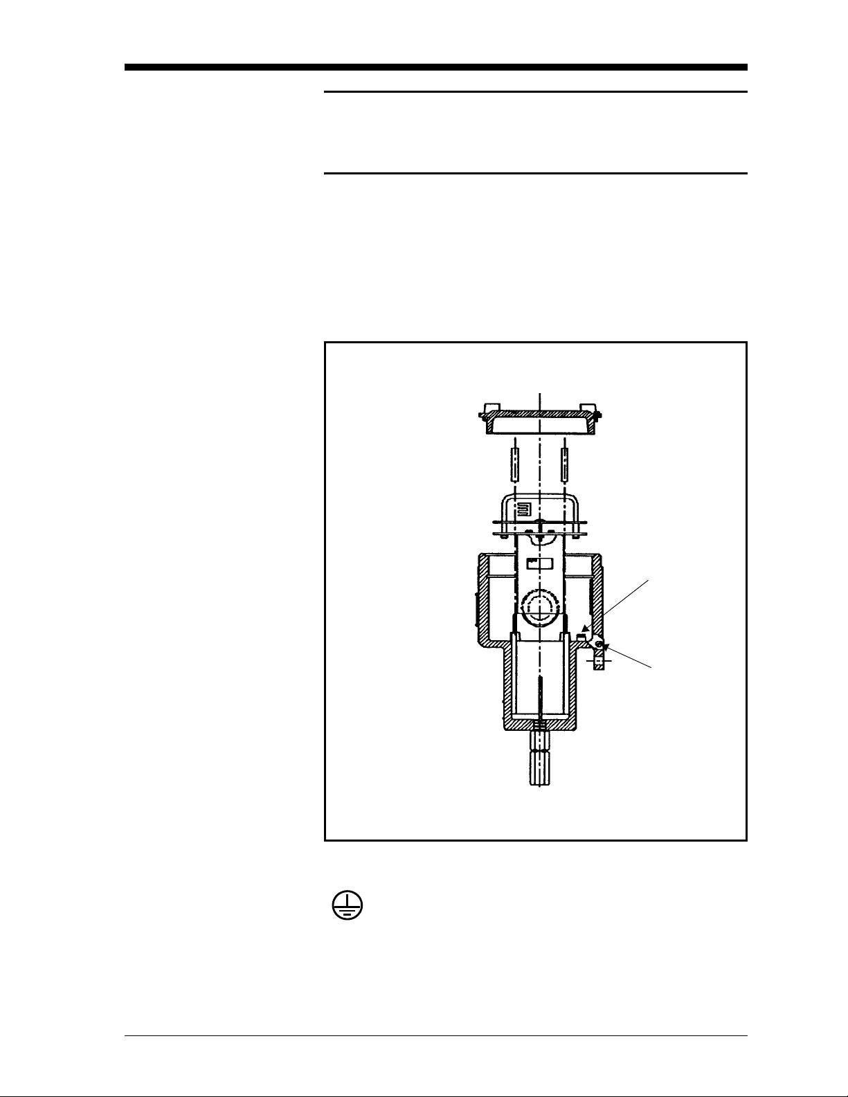
grounded. This can be done using an external ground screw on the
TMO2-TC, or, if required, an internal ground screw located below the
transmitter PCB. See Figure 2-4 below for the location of both ground
screws.
Figure 2-4: Location of Ground Screws
= Protective Conductor Terminal
Internal
Ground
Screw
External
Ground
Screw
Installation 2-7
Page 28
11/1/95
Wiring the TMO2-TC
Transmitter (cont.)
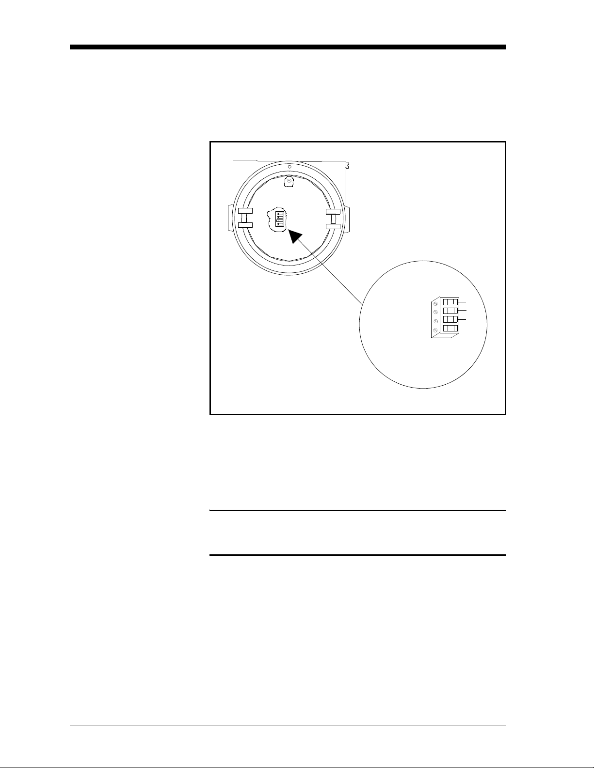
Wiring connections to the TMO2-TC Transmitter are made to
terminal block TB1, which is accessed by removing the TMO2-TC
cover. See Figure 2-5 below for the location and pin designations for
TB1. Also refer to Appendix C, Outline and Installation Drawings.
1
2
3
4
+24 VDC/1Amp
Return
Output Signal
No Connection
1
2
3
4
Red
Blk
Wht
Figure 2-5: TMO2-TC Wiring Connections
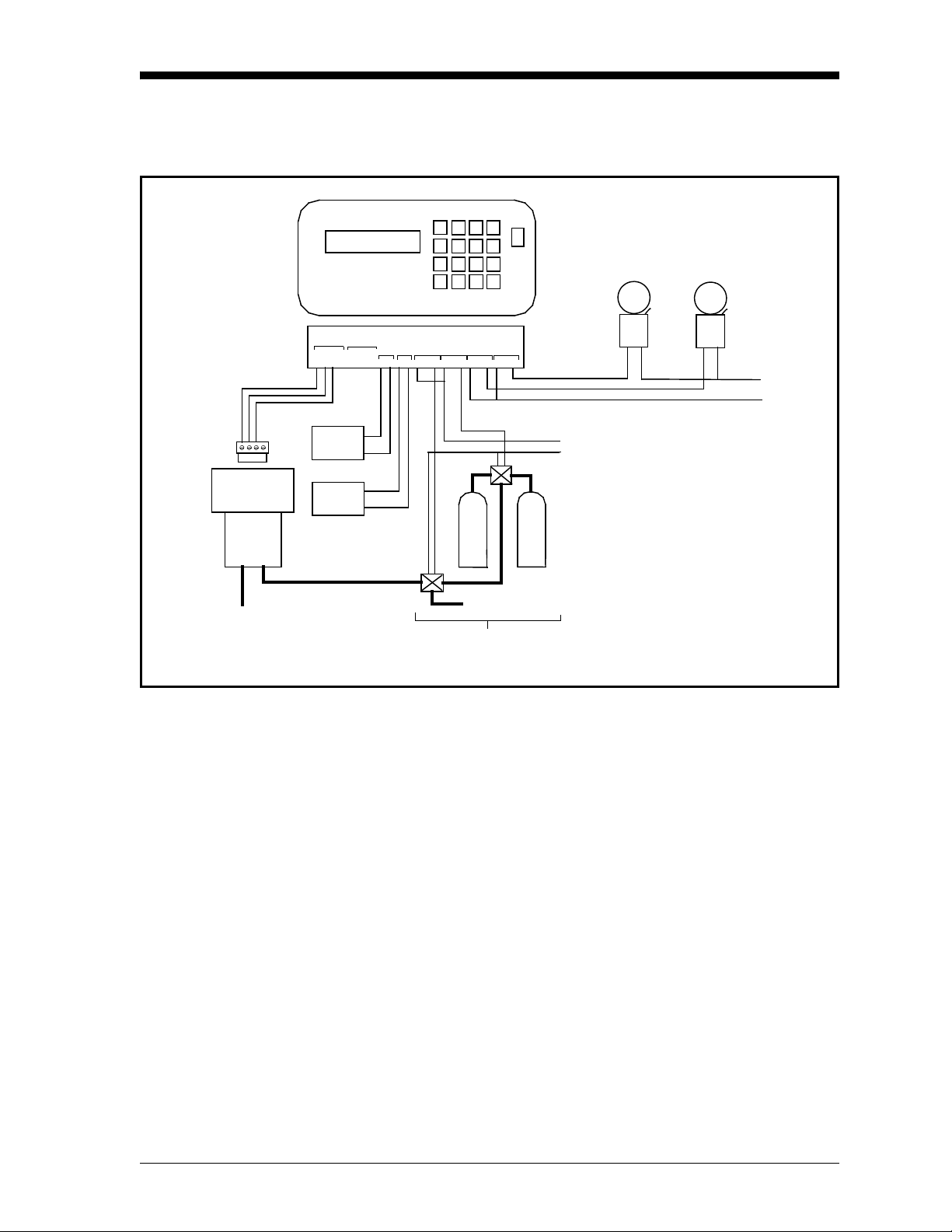
Wiring connections to the TMO2D-TC Display are made to the
terminal block labeled OXYGEN CELL at the rear of the TMO2DTC. See Figure 2-6 on the following page for the location of the
OXYGEN CELL terminal block.
Caution!
Do not make any connections to unassigned or unused
terminals.
2-8 Installation
Page 29
Wiring the TMO2-TC
Transmitter (cont.)
11/1/95
14
32
TMO2-TC
Outlet
TMO2D-TC
OXYGEN
SPARE
Cell
+24V
RTN
REC
REC
B
RECORDERS
INPUTS
COMP
0/4-20 mA
+24V
RTN
REC A REC B
IN2
IN1
OX
+
-
+
_
A
+
_
+
-
AUTOCAL
PROCESS CAL
C NC NO
C NC NO
ALARMS
LOW HIGH
C NC NOC NC NO
Zero
Gas
Span
Gas
Process Gas Inlet
Auto-Calibration System
High
Alarm
Solonoid Valve
Power
Low
Alarm
Alarm
Power
Figure 2-6: TMO2D-TC Wiring Connections
Installation 2-9
Page 30

May 2003
Wiring the TMO2-TC
Transmitter (cont.)
Table 2-2 below shows the transmitter to display module wiring
connections using the standard GE Panametrics TMO2D-TC cable.
This cable can be used for distances up to 2,800 ft (850 m). If you are
using your own cable, refer to Table 2-2 for cable requirements.
Table 2-1: Cable Requirements
Max Cable Length Cable Size
Sq.
Feet Meters AWG
450 130 22 0.35
700 200 20 0.6
1,050 320 18 1.0
1,700 500 16 1.2
2,800 850 14 2.0
4,000 1,200 12 3.0
Use the following steps to make the proper connections:
Millimeters
1. Route the cable into the transmitter through one of the 3/4"
conduit holes.
!WARNING!
BE SURE TO PLUG UP THE UNUSED CONDUIT
HOLE ON THE SIDE OF THE TRANSMITTER IN
ORDER TO MAINTAIN THE APPROPRIATE
WEATHERPROOF OR EXPLOSION-PROOF
RATING.
2. Unplug TB1 by carefully pulling it directly up without bending the
pins attached to the PCB.
3. Loosen the TB1 side screws and insert the colored wires into the
corresponding openings on top of TB1. See Table 2-1 above for
color-coded pin designations.
!WARNING!
BE SURE THAT +24 VDC (RED WIRE) IS
CONNECTED TO TERMINAL TB1-1. CONNECTING
+24 VDC POWER TO ANY OTHER TERMINAL WILL
DAMAGE THE TMO2-TC PCB, REQUIRING
FACTORY REPAIR.
2-10 Installation
Page 31

11/1/95
Wiring the TMO2-TC
Transmitter (cont.)
Table 2-2: Transmitter Power and Output Connections
Transmitter
Wire Color Gage
+24 VDC Red 14 AWG Pin 1 +24V
Return Black 14 AWG Pin 2 RTN
Signal White 22 AWG Pin 3 OX
4. Tighten the side screws, and carefully plug TB1 back onto the
PCB.
5. Connect the other end of the cable in a similar manner to the
OXYGEN CELL terminal block located on the rear panel of the
TMO2D-TC Display. See Table 2-1 on the previous page for
color-coded pin designations.
TB1 Display
Installation 2-11
Page 32

1/20/97
Wiring the TMO2D-TC Display
Figure 2-6 on page 2-9 shows possible output wiring connections
between the TMO2D-TC Display and recorders, alarms, and
automatic sample systems. Note that the standard TMO2D-TC has a
single, non-isolated 0/4-20 mA output (RCDR A) and dual Form C
SPDT alarm relays (ALARMS). Dual isolated 0/4-20 mA outputs
(RCDR A/RCDR B) and dual auto calibration (Auto Cal) relays are
optional.
The alarm relays can be wired in a “fail-safe” configuration that will
allow a contact closure when the H
level falls below a certain point
2
or rises above a certain point, or when a power failure occurs. For
example, to have a contact closure when the H
level falls below 1%
2
or rises above 5%, or in the event of a power failure, do the following:
TMO2D-TC Alarm Wire Program For Use As
LOW COM/NC 5% H
HIGH COM/NC
1% H
2
2
HIGH
LOW
Note: See Chapter 4, Programming the TMO2D-TC, The Alarms
Menu, for information on programming the alarm set points.
When the LOW alarm is wired and programmed as above, a loss of
power or an H
reading greater than 5% causes a contact closure that
2
can be used as a HIGH or “fail-safe” alarm.
When the HIGH alarm is wired and programmed as above, a loss of
power or an H
reading less than 1% causes a contact closure that can
2
be used as a LOW or “fail-safe” alarm.
!ATTENTION EUROPEAN CUSTOMERS!
IN ORDER TO MEET CE MARK REQUIREMENTS,
YOU MUST SHIELD AND GROUND ELECTRICAL
CABLES AS DESCRIBED IN APPENDIX H.
!WARNING!
TO ENSURE THE SAFE OPERATION OF THE
TMO2D-TC, YOU MUST INSTALL AND OPERATE IT
AS DESCRIBED IN THIS MANUAL. IN ADDITION, BE
SURE TO FOLLOW ALL APPLICABLE SAFETY
CODES AND REGULATIONS FOR INSTALLING
ELECTRICAL EQUIPMENT IN YOUR AREA.
PROCEDURES SHOULD BE PERFORMED BY
TRAINED SERVICE PERSONNEL.
2-12 Installation
Page 33

1/20/97
Wiring the TMO2D-TC
Display (cont.)
The TMO2D-TC also has a bi-directional, industry standard RS232C
serial port, which can be connected to a terminal or PC that supports
the RS232C protocol. Figure 2-7 below shows the wiring pin
designations. The 25-pin, male D connector is located at the right on
the rear of the TMO2D-TC Display.
J8
Pin 14
Pin 1
Pin 2 = Transmit
(from)
Pin 3 = Receive (to)
Pin 7 = Return (ground)
Figure 2-7: RS232C Wiring Connections
Installation 2-13
Page 34

1/20/97
Wiring the TMO2D-TC
Display (cont.)
The TMO2D-TC Display is connected to 100/120/220/240 VAC
power using the supplied power cord.
Caution!
The interconnecting wiring between the TMO2-TC
Transmitter and TMO2D-TC Display must be completed
before powering up.
Note: The power cord is the main disconnect device.
Note: = Protective Conductor Terminal
IMPORTANT: To comply with the European Low Voltage Directive,
you must install a switch or circuit breaker on the
input power line. For greatest safety, locate the
circuit breaker or switch near the unit that the line
serves.
2-14 Installation
Page 35

Chapter 3
Page 36

Operation
Overview . . . . . . . . . . . . . . . . . . . . . . . . . . . . . . . . . . . . . . . . . . . . . .3-1
Introduction . . . . . . . . . . . . . . . . . . . . . . . . . . . . . . . . . . . . . . . . . . .3-1
Powering Up the TMO2D-TC Analyzer . . . . . . . . . . . . . . . . . . . . . .3-1
Establishing a Flow of Sample Gas . . . . . . . . . . . . . . . . . . . . . . . .3-2
Operating the TMO2D-TC Display. . . . . . . . . . . . . . . . . . . . . . . . . .3-3
Page 37

1/20/97
Overview This chapter provides information on operating the TMO2D-TC
analyzer. You will find the following topics discussed:
• Introduction — A brief discussion of operational considerations.
• Powering Up the TMO2D-TC Analyzer — How to start the
TMO2D-TC.
• Establishing a Flow of Sample Gas — Basic sample gas
considerations.
• Operating the TMO2D-TC Display — A description of the
TMO2D-TC LCD display and keypad.
Introduction The TMO2D-TC operation consists of only three steps:
1. Supplying power to the analyzer and turning it on.
2. Establishing a flow of sample gas through the system.
Powering Up the TMO2D-TC Analyzer
3. Operating the display module.
If you have not already done so, please read Chapter 2, Installation,
for details on mounting and wiring the TMO2-TC Transmitter, the
sample system, and the TMO2D-TC Display.
The TMO2D-TC Display has a power switch located at the top right
of the front panel. It will begin operation as soon as it is turned to the
ON position.
Note: The power cord is the main disconnect device.
Note: If your TMO2D-TC was supplied in a weatherproof enclosure
or was modified for use in Class I, Div. 2 hazardous areas, the
power switch will be inoperative. The TMO2D-TC will begin
operating as soon as it is connected to a 100/120/220/240
VAC power source.
The TMO2D-TC Display will provide 24 VDC power to the TMO2TC Transmitter. Because the transmitter is controlled at a constant
o
C (131oF) operating temperature, allow 30 minutes for the unit to
55
warm up and reach temperature stability. During this time, you can
establish a sample gas flow through the sample system.
IMPORTANT: To comply with the European Low Voltage Directive,
you must install a switch or circuit breaker on the
input power line. For greatest safety, locate the
circuit breaker or switch near the unit that the line
serves.
Operation 3-1
Page 38

May 2003
Powering Up the
TMO2D-TC Analyzer
(cont.)
Establishing a Flow of Sample Gas
When the display module is first turned on, it will show the firmware
version installed. For example:
GE Panametrics
TMO2D STD.00X.X
Next it will do some internal testing:
GE Panametrics
Testing RAM ... Passed.
The above sequence should take about 10 seconds. The display
module then begins taking measurements from the transmitter, and
the LCD displays the gas concentration, the time, and the Alarm
status. Allow the transmitter 30 minutes to warm up before accepting
data from the TMO2D-TC.
Open the necessary valves to establish a sample gas flow of 0.5 SCFH
(250 cc/min) at atmospheric pressure. Make sure that nothing
obstructs the flow of sample gas, thereby causing a pressure build-up
in the sensing chamber. For proper operation, the TMO2-TC
Transmitter should be vented to atmosphere.
Note: Unless otherwise specified, the TMO2-TC is factory
calibrated at atmospheric pressure and 0.5 SCFH (250 cc/
min) and should therefore be operated at atmospheric
pressure. Operating the TMO2-TC at any other pressure will
necessitate a field calibration at that pressure in order to
maintain accuracy. See Chapter 5, Calibration.
If you are using the 4-Port (flowing reference gas) configuration,
open the necessary valves to establish a reference gas flow of 0.5
SCFH (250 cc/min) at atmospheric pressure. Note that you can use a
reference gas flow as low as 5 cc/min in order to conserve gas.
3-2 Operation
Page 39

May 2003
Operating the TMO2DTC Display
The TMO2D-TC Display has a 2-line x 24 character backlit Liquid
Crystal Display (LCD) screen, and a 16-key keypad (see Figure 3-1).
After displaying the firmware version and testing RAM, the display
module enters Operate Mode.
Figure 3-1: TMO2D-TC Display and Keypad
LCD Display In Operate Mode, the left side of the top line of the LCD shows the
name of the gas being measured (e.g., H
the factory according to initial specifications. If you should need to
change the name of the gas, refer to Appendix E, Special
Programming. This manual will refer to the gas being measured as
. The left side of the bottom line shows the gas concentration in %
H
2
(see Figure 3-1 above).
The right side of the top line is a clock. When the TMO2D-TC is
powered up, this clock will start from 00:00:00. The current time (and
date) can be entered in Programming Mode (see Chapter 4,
Programming the TMO2D-TC). However, if power to the TMO2DTC is interrupted, the clock will be reset to 00:00:00.
The right side of the bottom line displays the alarm status. The word
“Alarm:” is displayed. If the HIGH alarm is activated, an “H” will be
displayed in reverse lettering. If the LOW alarm is activated, an “L”
will be displayed.
, N2, SO2, CO2). It was set at
2
Keypad Except for the No key, which is used to enter Programming Mode, the
keypad does not function in Operate Mode. Pressing any other key
will activate the display backlight.
Operation 3-3
Page 40

Chapter 4
Page 41

Programming
Overview . . . . . . . . . . . . . . . . . . . . . . . . . . . . . . . . . . . . . . . . . . . . . .4-1
Introduction . . . . . . . . . . . . . . . . . . . . . . . . . . . . . . . . . . . . . . . . . . .4-2
Key Functions. . . . . . . . . . . . . . . . . . . . . . . . . . . . . . . . . . . . . . . . . .4-3
Entering Programming Mode . . . . . . . . . . . . . . . . . . . . . . . . . . . . .4-5
Menu Navigation. . . . . . . . . . . . . . . . . . . . . . . . . . . . . . . . . . . . . . . .4-5
The Main Menu . . . . . . . . . . . . . . . . . . . . . . . . . . . . . . . . . . . . . . . . .4-6
Page 42

11/1/95
Overview This chapter provides information on programming the TMO2D-TC
Display using either the 16-key keypad or the RS232C serial port.
You will find the following topics discussed:
• Introduction — A brief overview of the TMO2D-TC user program.
• Key Functions — Keypad key functions and their RS232C
equivalents when in Programming Mode.
• Entering Programming Mode — How to enter Programming Mode
from Operate Mode in order to access the user program.
• Menu Navigation — How to navigate the TMO2D-TC menu
structure.
• The Main Menu — A description of the Main menu functions.
• The Setup Menu — A description of the Setup menu functions.
• The Recorders Menu — A description of the Recorders menu
functions.
• The Alarms Menu — A description of the Alarms menu functions.
• The Tests Menu — A description of the Tests menu functions.
• The Calibration Menu — A description of the Calibration menu
functions.
Programming 4-1
Page 43

11/1/95
Introduction The TMO2D-TC Display contains an interactive, user-friendly
program that allows the user to customize the TMO2D-TC to their
application and change operating parameters as desired. The program
is accessed through the TMO2D-TC keypad and LCD display, or the
RS232C serial port using an ASCII terminal or PC.
Data entered into the TMO2D-TC by the user overrides any
previously entered data, and is retained in memory for several years,
even if power to the TMO2D-TC is interrupted.
Note: The time in the TMO2D-TC is reset to 00:00:00 if power is
interrupted. The date information is retained if power is
interrupted, but may be incorrect if power is not restored
immediately. Both date and time should be re-entered in the
event of power interruption.
!WARNING!
IF THE CABLE CONNECTING THE TMO2D-TC
DISPLAY TO THE TMO2-TC TRANSMITTER IS
DISCONNECTED WHILE THE TMO2D-TC IS
POWERED UP, DATA MAY BE LOST. ALWAYS
REMOVE POWER FROM THE DISPLAY MODULE
BEFORE DISCONNECTING THE TMO2D-TC TO
TMO2-TC CABLE.
4-2 Programming
Page 44

11/1/95
Key Functions When the TMO2D-TC is in Operate Mode, it will ignore all keys
except the No key. On receipt of a No, the LCD will display Enter
Code:, and await the user program entry code, 1 2 3. During code
entry, the TMO2D-TC continues to update the data display, alarm
status, and recorder output.
If the correct code is entered, the TMO2D-TC switches to
Programming Mode. While it is in Programming Mode, data
collection is suspended, and alarm status and recorder outputs are
held at their current values.
In Programming Mode, the keypad keys are divided into three
groups: Yes/No, Selector, and Data Entry:
Ye s / No : The Yes key is used to select a displayed menu option
or to confirm a numeric entry. The No key is used to
scroll forward to the next menu option or to clear a
numeric entry.
Selector: The Left and Right Arrow keys are used as selector
keys. The Left Arrow key is used to step backward
through a displayed list of menu options, or as a backspace (erase) key during numeric entry. The Right
Arrow key is used to step forward through a displayed
list of menu options. It is equivalent to the No key.
Data
The 0-9, -, and . keys are used to enter numeric values.
Entry:
All keypad and most display operations can be performed remotely
on the RS232C serial port using a terminal or PC that supports the
RS232C protocol. Table 4-1 on the next page provides a list of
keypad keys (left column) and their ASCII (center column) and
terminal/PC (right column) equivalents.
Programming 4-3
Page 45

11/1/95
Key Functions (cont.)
Table 4-1: TMO2D-TC RS232C Serial Port
Corresponding Keys
TMO2D-TC
Keypad ASCII Terminal/PC Keys
0 030 0
1 031 1
2 032 2
3 033 3
4 034 4
5 035 5
6 036 6
7 037 7
8 038 8
9 039 9
-02D-
.02E.
Y00DENTER_
N 01B ESCAPE
←
008 BACKSPACE
→
020 SPACE BAR
4-4 Programming
Page 46

11/1/95
Entering Programming Mode
When the TMO2D-TC is turned on, it enters Operate Mode (after
approx. 10 seconds). In order to enter data into the user program or to
check previously entered values, the TMO2D-TC must be switched to
Programming Mode. To enter Programming Mode:
1. Press the No key.
2. The top line of the display will show Enter Code:
3. Key in the code 1 2 3, pressing each key slowly and firmly. The
display will show an * after each digit is entered.
Note: If an incorrect code is entered, or a non-numeric (Yes/No or
Arrow) key is pressed, or the keys are pressed too quickly, the
TMO2D-TC will return to Operate Mode, and the user must
press No again to re-enter the code.
4. The display will now show:
MAIN MENU
Setup?
5. The TMO2D-TC is now in Programming Mode, ready for user
input.
Menu Navigation When a menu item is being displayed, the first line of the LCD shows
the title of the current menu in capital letters. The second line shows
the current menu option followed by a question mark. Press Yes to
select a displayed option, No or Right Arrow to move on to the next
option, or Left Arrow to move back to the previous option.
Note: The menu options are circular — skipping over the last option
in the list returns to the first option.
Programming 4-5
Page 47

11/1/95
The Main Menu The Main menu consists of six submenus: Setup, Recorders, Alarms,
Tests, Calibration, and Resume. Selecting Resume returns the
TMO2D-TC to Operate Mode. Refer to Appendix D, Menu Flow
Diagrams, for a flow diagram of the Main menu.
The Setup Menu The Setup menu consists of seven options: Set Time, Set Date, Set
Backlight, Set Display, Set Communications, Set Error Handling, and
Done. These options allow the user to change basic operating
parameters. Selecting Done returns the TMO2D-TC to the Main
menu. Refer to Appendix D, Menu Flow Diagrams, for a flow
diagram of the Setup menu.
Set Time
Set Time sets the current time in 24-hour format. For example, to
enter 1:15 PM (13.15 in 24-hour time):
MAIN MENU
Setup?
SETUP MENU
Set Time?
Enter 24 hour time:
HH.MM [XX.XX]: 13.15
SETUP MENU
Set Time?
Press Yes to enter the Setup
menu.
Press Yes to set the time.
Use the Data Entry keys to enter
13.15 (the X’s represent the
previous entry). Press Yes to
confirm the entry; then press Yes
again to exit.
Press No to move to the next
option on the Setup menu.
4-6 Programming
Page 48

11/1/95
Set Date
Set Date sets the current date in USA (month, day, year) format. For
example, to enter August 12, 1994:
SETUP MENU
Set Date?
Enter Date (MM.DD.YY):
XX.XX.XX]: 08.12.94
Press Yes to set the date.
Use the Data Entry keys to enter
08.12.94 (the X’s represent the
previous entry). Press Yes to
confirm the entry; then press Yes
again to exit.
SETUP MENU
Set Date?
Press No to move to the next
option on the Setup menu.
Set Backlight
The LCD contains an electro-luminescent (EL) panel to enhance the
readability of the screen in dim light. EL panels have a finite life
span, dimming with use. To maintain the life of the EL backlight, the
TMO2D-TC will automatically turn the backlight off after a
predetermined time period. The backlight time-out period can be set
from 0 (never on) to 60 minutes. The default is 3 minutes. For
example, to enter a time-out of 10 minutes:
SETUP MENU
Set Backlight?
SETUP MENU
Remain ON (min) [XX]: 10
Press Yes to set the backlight
time-out period.
Use the Data Entry keys to enter
10 (the X’s represent the
previous entry). Press Yes to
confirm the entry; then press Yes
again to exit.
SETUP MENU
Set Backlight?
Press No to move to the next
option on the Setup menu.
Set Display
This option is not applicable to the TMO2D-TC and should not be
used.
SETUP MENU
Set Display?
Press No to move to the next
option on the Setup menu.
Programming 4-7
Page 49

11/1/95
Set Communications
The Set Communications menu consists of three options: Set Baud
Rate, Set Update Rate, and Done. These options allow the user to
change RS232C communications parameters. Selecting Done returns
the TMO2D-TC to the Setup menu. Refer to Appendix D, Menu Flow
Diagrams, for a flow diagram of the Set Communications menu.
Set Baud Rate
The TMO2D-TC supports communications rates of 9600, 4800,
2400, 1200, and 300 baud. The default setting is 9600 baud, Word
size is fixed at 8 bits, 1 stop bit, NO parity.
Note: The use of 300 baud greatly limits the computation speed of
the TMO2D-TC, and is not recommended. It is provided solely
for compatibility with older equipment.
SETUP MENU
Set Communications?
SET COMMUNICATIONS
Set Baud Rate?
SELECT BAUD RATE
9600 baud?
Press Yes to enter the Set
Communications menu.
Press Yes to set the baud rate.
Use the No or Arrow keys to
scroll through the choices (9600,
4800, 2400, 1200, 300). Press
Yes to select the desired baud
rate and exit to the Set
Communications submenu.
Note: The baud rate can also be changed via a terminal/PC
connected to the RS232C port; however, this practice is not
recommended. Since the TMO2D-TC will immediately change
to the new baud rate, the display and keyboard operation will
not be correct until the baud rate of the terminal/PC is
changed to match the new baud rate set in the TMO2D-TC.
4-8 Programming
Page 50

11/1/95
Set Update Rate
This option is used to change the interval at which data is sent to the
RS232C serial port. The data update rate can be set from 0 (no data
sent) to 300 seconds. The default rate is 1 second. For example, to set
an update rate of 180 seconds:
SETUP MENU
Set Update Rate?
SET COMMUNICATIONS
Data Interval [XXX]: 180
SET COMMUNICATIONS
Set Update Rate?
SET COMMUNICATIONS
Done?
SETUP MENU
Set Communications?
Press Yes to set the update rate.
Use the Data Entry keys to enter
180 (the X’s represent the
previous entry). Press Yes to
confirm the entry; then press Yes
again to exit.
Press No to move to the next
option on the SET
COMMUNICATIONS
submenu.
Press Yes to exit to the Setup
menu.
Press No to move to the next
option on the Setup menu.
Programming 4-9
Page 51

11/1/95
Set Error Handling
The Set Error Handling option is used to program the LCD, output(s),
and alarms to respond to an invalid H
over-range) that occurs when the TMO2D-TC is in Operate mode. An
invalid measurement occurs if the H
mA or greater.
measurement (under-range or
2
reading is 1 mA or less, or 24
2
Note: Error handling for an invalid H
measurement is independent
2
of error handling for Auto Cal (see “Auto Cal Parameters” in
the Calibration menu). If both error conditions occur
simultaneously, error handling for the invalid H
2
measurement will take precedence.
Follow the steps below to enable Error Handling, set the LCD, and
select the output and alarm responses:
SETUP MENU
Set Error Handling?
Enable Error Handling:
[YES] no
Press Yes to select the Set Error
Handling option.
Press the No or the Arrow keys
to select YES. Press Yes to
confirm.
Note: If you select NO and press Yes to confirm, you will be
immediately returned to the Setup menu.
SYSTEM ERROR EFFECTS
Set Display Response?
Press Yes to set the LCD
response.
Display System Error?
yes [NO]
Press the No or the Arrow keys
to select your choice. Press Yes
to confirm.
SYSTEM ERROR EFFECTS
Set Display Response?
Press No to move to the next
option on the System Error
Effects menu.
SYSTEM ERROR EFFECTS
Set Alarm Response?
4-10 Programming
Press Yes to set the alarm
response.
Page 52

Set Error Handling (cont.)
11/1/95
Select Alarm Effect?
No Effect?
Select Alarm Effect?
Trip High?
Select Alarm Effect?
Trip Low?
Select Alarm Effect?
Trip Both?
SYSTEM ERROR EFFECTS
Set Alarm Response?
SYSTEM ERROR EFFECTS
Set Recorder Response?
Select Recorder Effect?
No Effect?
Select Recorder Effect?
Force High?
Use the No or Arrow keys to
scroll through the choices and
press Yes at your choice.
Press No to move to the next
option on the System Error
Effects menu.
Press Yes to set the recorder
output(s) response.
Use the No or Arrow keys to
scroll through the choices and
press Yes at your choice.
Select Recorder Effect?
Force Low?
Select Recorder Effect?
Hold Last Value?
SYSTEM ERROR EFFECTS
Set Recorder Response?
SYSTEM ERROR EFFECTS
Done?
Press No to move to the next
option on the System Error
Effects menu.
Press Yes to return to the Setup
menu.
Programming 4-11
Page 53

11/1/95
Set Error Handling (cont.)
SETUP MENU
Set Error Handling?
SETUP MENU
Done?
MAIN MENU
Setup?
Press No to move to the next
option on the Setup menu.
Press Yes to return to the Main
menu.
Press No to move to the next
option on the Main menu.
4-12 Programming
Page 54

11/1/95
The Recorders Menu The Recorders menu is used to scale the 0/4-20 mA analog output(s).
Selecting A allows the user to scale the first analog output. Selecting
B allows the user to scale the second analog output (if one is present).
Selecting Done returns the TMO2D-TC to the Main menu. Refer to
Appendix D, Menu Flow Diagrams, for a flow diagram of the
Recorders menu.
The TMO2D-TC provides a choice of one non-isolated 0/4-20 mA
output, or two isolated 0/4-20 mA outputs. Both recorder options can
be set for a 0-20 mA or 4-20 mA response, and can be scaled
anywhere within the range of the transmitter.
Note: The TMO2D-TC user program will accept settings for two
outputs, A and B. However, if the TMO2D-TC has been
purchased with only a single, non-isolated 0/4-20 mA output,
only recorder A is effective.
Use the steps in the following example to set up recorders A and B.
We will set recorder A for a 4-20 mA output, with 4 mA equal to 0%
and 20 mA equal to 100% H2.
H
2
MAIN MENU
Setup?
MAIN MENU
Recorders?
Select Recorder to set:
[A] B done
Rcd A Output (mA):
0-20 [4-20]
Recorder A 4 mA Value
%H2 [XX.XX]: 0.00
Recorder A 20 mA Value
%H2 [XXX.XX]: 100.00
Press No or Right Arrow until
Recorders? appears.
Press Yes to enter the Recorders
menu.
Press No or the Arrow keys to
select A. Press Yes to confirm
the entry.
Press No or the Arrow keys to
select 4-20. Press Yes to confirm
the entry.
Use the Data Entry keys to enter
0.00 (the X’s represent the
previous entry). Press Yes to
confirm the entry; then press Yes
again to exit.
Use the Data Entry keys to enter
100.00 (the X’s represent the
previous entry). Press Yes to
confirm the entry; then press Yes
again to exit.
Programming 4-13
Page 55

11/1/95
The Recorders Menu
(cont.)
Select Recorder to set:
[A] B done
MAIN MENU
Recorders?
Recorder B is scaled in the same
manner. After Recorder B is
scaled, use the No or Arrow keys
to select DONE. Press Yes to
return to the Main menu.
Press No to move to the next
option on the Main menu.
4-14 Programming
Page 56

11/1/95
The Alarms Menu The TMO2D-TC is provided with two single-pole double throw
(SPDT), Form C alarm relays for use in activating alarm devices. See
Chapter 6, Specifications, for details on relay specifications, and
Chapter 2, Installation, for wiring recommendations. Both relays
provide a normally-open (NO) and a normally-closed (NC) set of
contacts. The alarms are addressed as HIGH or LOW. The HIGH
alarm relay will change state when the current reading becomes
greater than or equal to the HIGH alarm set point. The LOW alarm
relay will change state when the current reading becomes less than or
equal to the LOW alarm set point. Refer to Appendix D, Menu Flow
Diagrams, for a flow diagram of the Alarms option.
Use the steps in the following example to set the HIGH and LOW
alarm relays. We will set the HIGH alarm relay to 75% H
LOW alarm relay to 25% H
.
2
, and the
2
MAIN MENU
Setup?
MAIN MENU
Alarms?
Select Alarm to set:
[HIGH] low done
Enter Alarm Setpoint:
High %H
Select Alarm to set:
[HIGH] low done
Enter Alarm Setpoint:
Low %H
Select Alarm to set:
high [LOW] done
MAIN MENU
Alarms?
[XX.XX]:
2
[XX.XX]:
2
Press No or Right Arrow until
Alarms? appears.
Press Yes to enter the Alarms
menu.
Press No or the Arrow keys to
select HIGH. Press Yes to
confirm the entry.
Use the Data Entry keys to enter
75.00 (the X’s represent
the previous entry). Press Yes to
confirm the entry; then press Yes
again to exit.
Press No or the Arrow keys to
select LOW. Press Yes to
confirm the entry.
Use the Data Entry keys to enter
25.00 (the X’s represent the
previous entry). Press Yes to
confirm the entry; then press Yes
again to exit.
Press No or the Arrow keys to
select DONE. Press Yes to return
to the Main menu.
Press No to move to the next
option on the Main menu.
Programming 4-15
Page 57

11/1/95
The Tests Menu The Tests menu consists of four options: DVM Test, Recorder
Calibrate, Alarms Test, and Done. These options allow the user to
perform operational tests on the analog outputs and alarm relays, and
to directly measure the raw signal from the TMO2-TC Transmitter.
Selecting Done returns the TMO2D-TC to the Main menu. Refer to
Appendix D, Menu Flow Diagrams, for a flow diagram of the Tests
menu.
DVM Test
The DVM test allows the TMO2D-TC to operate as a simple, digital
voltmeter to measure, in milliamps, the signal being received from
the TMO2-TC Transmitter. The TMO2D-TC is updated
approximately twenty times per second, facilitating connection and
calibration of the TMO2-TC Transmitter.
Follow the steps below to test the input signal from the TMO2-TC
Transmitter:
MAIN MENU
Setup?
MAIN MENU
Te st s?
TESTS
DVM Test?
Select DVM Input:
[GAS] comp done
Press No or Right Arrow until
Tests? appears.
Press Yes to enter the Tests
menu.
Press Yes to enter the DVM test
option.
Press No or the Arrow keys to
select GAS. Press Yes to
confirm.
Note: The COMP option is not applicable to the TMO2D-TC, and
should not be used. If you select COMP by mistake, you
should see:
H2 DVM TEST
0.00 mA
Press any key to exit.
4-16 Programming
Page 58

The Tests Menu (cont.)
11/1/95
H2 DVM TEST
XX.XX mA
The X’s represent the mA signal
from the TMO2-TC Transmitter,
which will update continuously.
Press any key to exit.
Select DVM Input:
[GAS] comp done
Press No or the Arrow keys to
select DONE. Press Yes to exit
to the Tests menu.
TESTS
DVM Test?
Press No to move to the next
option on the Tests menu.
Recorder Calibrate
The Recorder Calibrate test allows a selected % gas composition to
be output to the recording device to facilitate adjustment of the
device’s zero and span.
For example, to enter a %H
TESTS
Recorder Calibrate?
Select Recorder to test:
[A] B done
Set Recorder A to:
%H
[XX.XX]: 36.39
2
Select Recorder to test:
[A] B done
TESTS
Recorder Calibrate?
of 36.39 to be output to recorder A:
2
Press Yes to enter the Recorder
Calibrate option.
Press No or the Arrow keys to
select A. Press Yes to confirm
the entry.
Use the Data Entry keys to enter
36.39 (the X’s represent the
previous entry). Press Yes to
confirm the entry; then press Yes
again to exit.
Recorder B (if present) is tested
in the same manner. After you
are done, press No or the Arrow
keys to select DONE. Press Yes
to exit to the Tests menu.
Press No to move to the next
option on the Tests menu.
Programming 4-17
Page 59

11/1/95
Alarms Test
The Alarms test enables you to trip and reset the alarm relays using
the keypad, in order to test the operation of external alarm devices
and circuits. For example, to test the HIGH alarm relay:
TESTS
Alarms Test?
Select Alarm to test:
[HIGH] low done
Press Yes to enter the Alarms test
option.
Press No or the Arrow keys to
select HIGH. Press Yes to
confirm the entry.
Turn High Alarm:
[ON] off done
Press No or the Arrow keys to
select ON. Press Yes to confirm.
Note: Upon selecting the ON option and pressing Yes, the HIGH
alarm relay will turn on, and the brackets will automatically
move to OFF.
Turn High Alarm:
on [OFF] done
Press Yes to turn the HIGH
alarm off.
Note: Upon selecting the OFF option and pressing Yes, the HIGH
alarm relay will turn off and the brackets will automatically
move to ON.
Turn High Alarm:
[ON] off done
Select Alarm to test:
[HIGH] low done
Press No or the Arrow keys to
select DONE. Press Yes to exit.
The LOW alarm is tested in
the same manner. After you
are done, press No or the Arrow
keys to select DONE. Press Yes
to exit to the Tests menu.
TESTS
Alarms Test?
TESTS
Done?
MAIN MENU
Te st s?
4-18 Programming
Press No to move to the next
option on the Tests menu.
Press Yes to return to the Main
menu.
Press No to move to the next
option on the Main menu.
Page 60

May 2003
The Calibration Menu The Calibration menu consists of three options: Auto Cal Parameters,
Edit Calibration Data, and Done. These options allow the user to
perform automatic zero and span calibration of the TMO2D-TC, and
to enter measurement parameters and calibration data. Selecting Done
returns the TMO2D-TC to the Main menu. Refer to Appendix D,
Menu Flow Diagrams, for a flow diagram of the Calibration menu.
Auto Cal Parameters
The TMO2D-TC can be programmed to perform an automatic
calibration procedure (Auto Cal) at specified time intervals ranging
from minutes to months. By performing measurements on two
calibration gases (zero and span), the TMO2D-TC can automatically
correct for changes in the response of the TMO2-TC Transmitter
without operator intervention. Auto Cal does not physically
recalibrate the TMO2-TC Transmitter, but instead creates a drift
curve to the TMO2-TC calibration data that is stored in memory in
the TMO2D-TC Display. Refer to Chapter 5, Calibration, for details
on manually calibrating the TMO2-TC Transmitter.
Note: Auto Cal requires the CAL option to be ordered with the
TMO2D-TC. It also requires a sample system with
electrically-actuated solenoid valves, and zero and span gases
for use during Auto Cal. See Figure 2-3 for a description of a
suitable sample system. If you do not presently have the Auto
Cal option or the proper sample system, please consult GE
Panametrics for assistance.
!WARNING!
USING THE AUTO CAL PROCEDURE WITHOUT
THE OPTIONS DESCRIBED ABOVE WILL
PRODUCE AN ERRONEOUS CALIBRATION AND
PREVENT PROPER OPERATION
OF THE TMO2D-TC.
At a user-specified time interval, the TMO2D-TC activates a solenoid
valve on the sample system. This isolates the transmitter from the
process stream, and connects it instead to the span calibration gas.
After a programmable equilibration time, to allow the span gas to
completely replace the process gas, measurements are taken of the
span calibration gas. The TMO2D-TC then activates a second
solenoid valve to connect to the zero calibration gas. After
equilibration, measurements are taken of the zero calibration gas. The
TMO2D-TC then reconnects the transmitter to the process stream. A
final settling time takes place while the process gas completely
replaces the zero gas.
Programming 4-19
Page 61

11/1/95
The Calibration Menu
(cont.)
Once settling has been completed, if no error has occurred, the
TMO2D-TC calculates the amount of drift from the TMO2-TC
Transmitter calibration, and creates a drift curve that is applied to the
transmitter calibration data for future measurements. The transmitter
calibration data is not changed.
If the Auto Cal measurements were out of range, the data is
disregarded, and the TMO2D-TC uses the drift curve already stored
in memory. If Auto Cal Error Handling is enabled, the display, analog
output, and alarms will respond to the out-of-range Auto Cal as
programmed.
MAIN MENU
Setup?
MAIN MENU
Calibration?
CALIBRATION MENU
Auto Cal Parameters?
Press No or Right Arrow until
Calibration? appears.
Press Yes to enter the Calibration
menu.
Press Yes to enter the Auto Cal
parameters option only if you
have the proper equipment. See
Note and WARNING above.
Otherwise, press No or the
Arrow keys to move to the next
option on the Calibration menu.
Enable AutoCal:
[YES] no
Press the No or the Arrow keys
to select YES. Press Yes to
confirm.
Note: If you select NO and press Yes to confirm, Auto Cal will be
disabled and you will be immediately returned to the
Calibration Menu.
The Auto Calibration menu consists of nine options: Set Time
Interval, Set Zero Gas, Set Span Gas, Set Settling Time, Set Error
Handling, Perform AutoCal, Zero AutoCal, View Drift Curve, and
Done. These options allow the user to control all aspects of the Auto
Cal operation. Selecting Done returns the TMO2D-TC to the
Calibration menu. Refer to Appendix D, Menu Flow Diagrams, for a
flow diagram of the Auto Calibration menu.
4-20 Programming
Page 62

11/1/95
Set Time Interval
The Set Time Interval option is used to set the time interval between
successive Auto Cal’s. This interval can be specified in either hours
or days.
Hours can be entered fractionally (e.g., 90 minutes = 1.5 hours) up to
a maximum of 24. An interval of 0 hours prevents Auto Cal from
occurring.
If a non-zero number of days is entered, the TMO2D-TC will prompt
for the time of day when Auto Cal should occur. Fractional days are
not allowed. Days can range from 0 to 99.
!WARNING!
IF YOU PROGRAM THE TMO2D-TC TO PERFORM
AN AUTO CAL AT A CERTAIN TIME BUT THE
TMO2D-TC TIME IS INCORRECT DUE TO A POWER
LOSS, THE TMO2D-TC WILL PERFORM THE AUTO
CAL AT THE WRONG TIME. MAKE SURE THAT THE
TMO2D-TC TIME IS SET CORRECTLY
(SEE SETUP MENU).
For example, to set the time interval to 12 hours:
AUTO CALIBRATION MENU
Set Time Interval?
Select AutoCal Interval:
[HOURS] days
Press Yes to select the Set Time
Interval option.
Press the No or the Arrow keys
to select HOURS. Press Yes to
confirm.
Auto-Cal Interval
Hours [XX.XX]: 12.00
Use the Data Entry keys to enter
12.00 (the X’s represent the
previous entry). Press Yes to
confirm the entry; then press Yes
to exit.
AUTO CALIBRATION MENU
Set Time Interval?
Press No to move to the next
option on the Auto Calibration
menu.
For another example, to set the time interval to 3 days, to occur at
1:45 PM:
AUTO CALIBRATION MENU
Set Time Interval?
Programming 4-21
Press Yes to select the Set Time
Interval option.
Page 63

11/1/95
Set Time Interval (cont.)
Select AutoCal Interval:
hours [DAYS]
Auto-Cal Interval
Days [XX]: 3
AutoCal at Time:
HH.MM [XX.XX]: 13.45
AUTO CALIBRATION MENU
Set Time Interval?
Press the No or the Arrow keys
to select DAYS. Press Yes to
confirm.
Use the Data Entry keys to enter
3 (the X’s represent the previous
entry). Press Yes to confirm the
entry; then press Yes again to
exit.
Use the Data Entry keys to enter
13.45 -1:45 PM in 24-hour
notation (the X’s represent the
previous entry). Press Yes to
confirm the entry; then press Yes
again to exit.
Press No to move to the next
option on the Auto Calibration
menu.
4-22 Programming
Page 64

11/1/95
Set Zero Gas
The Set Zero Gas option is used to enter the zero gas concentration
and equilibration time. The default concentration is 0%. After
entering the zero gas concentration, the TMO2D-TC will prompt for
the equilibration time for the zero gas. The equilibration time should
allow for the distance that the zero gas must travel from source to
TMO2-TC Transmitter, the flow rate, and the equilibration time of
the transmitter itself.
Note: For a successful Auto Cal to be performed, the equilibration
time should be a minimum of 3 minutes. The maximum
equilibration time is 30 minutes. For testing purposes, the
equilibration time can be as low as 10 seconds.
For example, to set the zero gas to 0% H
3 minutes:
AUTO CALIBRATION MENU
Set Zero Gas?
Zero Gas
%H2 [XX.XX]: 0.00
Press Yes to select the Set Zero
Gas option.
Use the Data Entry keys to enter
0.00 (the X’s represent the
previous entry). Press Yes to
confirm the entry; then press Yes
again to exit.
Zero Gas ON for
MM.SS [XX.XX]: 3
Use the Data Entry keys to enter
3 (the X’s represent the previous
entry). Press Yes to confirm the
entry; then press Yes again to
exit.
AUTO CALIBRATION MENU
Set Zero Gas?
Press No to move to the next
option on the Auto Calibration
menu.
with a equilibration time of
2
Programming 4-23
Page 65

11/1/95
Set Span Gas
The Set Span Gas option is used to enter the span gas concentration
and equilibration time. The default concentration is 10.00%. After
entering the span gas concentration, the TMO2D-TC will prompt for
the equilibration time for the span gas. The equilibration time should
allow for the distance that the span gas must travel from source to
TMO2-TC Transmitter, the flow rate, and the equilibration time of
the transmitter itself.
Note: For a successful Auto Cal to be performed, the equilibration
time should be a minimum of 3 minutes. The maximum
equilibration time is 30 minutes. For testing purposes, the
equilibration time can be as low as 10 seconds.
For example, to set the span gas to 100% H
of 3 minutes:
AUTO CALIBRATION MENU
Set Span Gas?
Span Gas
%H2 [XX.XX]: 0.00
Press Yes to select the Set Span
Gas option.
Use the Data Entry keys to enter
100.00 (the X’s represent the
previous entry). Press Yes to
confirm the entry; then press Yes
again to exit.
SpanGas ON for
MM.SS [XX.XX]: 3
Use the Data Entry keys to enter
3 (the X’s represent the previous
entry). Press Yes to confirm the
entry; then press Yes again to
exit.
AUTO CALIBRATION MENU
Set Span Gas?
Press No to move to the next
option on the Auto Calibration
menu.
with a equilibration time
2
Use the Data Entry keys to enter 100.0 (the X’s represent the previous
entry). Press Yes to confirm the entry; then press Yes again to exit.
4-24 Programming
Page 66

11/1/95
Set Settling Time
The Set Settling Time option is used to enter the amount of time the
process gas should remain on before the TMO2D-TC resumes taking
measurements. The settling time should allow for the distance that the
process gas must travel from source to TMO2-TC Transmitter, the
flow rate, and the settling time of the transmitter itself.
Note: For a successful Auto Cal to be performed, the settling time
should be a minimum of 3 minutes. The maximum settling time
is 30 minutes. For testing purposes, the settling time can be as
low as 10 seconds.
Note: The display, output, and alarms are not updated during the
settling period.
For example, to set the settling time to 3 minutes:
AUTO CALIBRATION MENU
Set Settling Time?
Settling Time:
MM.SS [XX.XX]: 3
AUTO CALIBRATION MENU
Set Settling Time?
Press Yes to select the Set
Settling Time option.
Use the Data Entry keys to enter
3 (the X’s represent the previous
entry). Press Yes to confirm the
entry; then press Yes again to
exit.
Press No to move to the next
option on the Auto Calibration
menu.
Programming 4-25
Page 67

11/1/95
Set Error Handling
The Set Error Handling option is used to program the LCD, output(s),
and alarms to respond to any invalid measurement that occurs during
Auto Cal. An invalid measurement would occur if the zero gas
reading was 1 mA or less, or the span gas reading was 24 mA or
greater, or either reading differed from the previous value by 1.6 mA
or more. If an invalid measurement does occur during Auto Cal, it
may be time to manually recalibrate the TMO2-TC Transmitter. See
Chapter 5, Calibration, for details.
Note: Error handling for Auto Cal is independent of error handling
for an invalid H
simultaneously, error handling for the invalid H
measurement. If both error conditions occur
2
2
measurement will take precedence.
Follow the steps below to enable Error Handling, set the LCD, and
select the output and alarm responses:
AUTO CALIBRATION MENU
Set Error Handling?
Enable Error Handling:
[YES] no
Press Yes to select the Set Error
Handling option.
Press the No or the Arrow keys
to select YES. Press Yes to
confirm.
Note: If you select NO and press Yes to confirm, you will be
immediately returned to the Auto Calibration menu.
SYSTEM ERROR EFFECTS
Set Display Response?
Display System Error?
yes [NO]
Press Yes to set the LCD
response.
Press the No or the Arrow keys
to select your choice. Press Yes
to confirm.
Auto Cal ERROR EFFECTS
Set Display Response?
Press No to move to the next
option on the Auto Cal Error
Effects menu.
Auto Cal ERROR EFFECTS
Set Alarm Response?
Press Yes to set the alarm
response.
4-26 Programming
Page 68

Set Error Handling (cont.)
11/1/95
Select Alarm Effect?
No Effect?
Select Alarm Effect?
Trip High?
Select Alarm Effect?
Trip Low?
Select Alarm Effect?
Trip Both?
AUTOCAL ERROR EFFECTS
Set Alarm Response?
AUTOCAL ERROR EFFECTS
Set Recorder Response?
Select Recorder Effect?
No Effect?
Select Recorder Effect?
Force High?
Use the No or Arrow keys to
scroll through the choices. Press
Yes at your choice.
Press No to move to the next
option on the Auto Cal Error
Effects menu.
Press Yes to set the recorder
output(s) response.
Use the No or Arrow keys to
scroll through the choices. Press
Yes at your choice.
Select Recorder Effect?
Force Low?
Select Recorder Effect?
Hold Last Value?
AUTOCAL ERROR EFFECTS
Set Recorder Response?
AUTOCAL ERROR EFFECTS
Done?
AUTO CALIBRATION MENU
Set Error Handling?
Press No to move to the next
option on the Auto Cal Error
Effects menu.
Press Yes to return to the Auto
Calibration menu.
Press No to move to the next
option on the Auto Calibration
menu.
Programming 4-27
Page 69

11/1/95
Perform AutoCal
The Perform AutoCal option is used to manually activate the Auto
Cal procedure without waiting for the specified Auto Cal interval.
When an Auto Cal is performed, either by pressing Yes at the
Perform AutoCal? prompt or when the specified time arrives, the
following sequence occurs:
1. The top line of the LCD changes to “*Auto Cal in Progress*.” At
this point the Process/Cal relay changes to the Cal state, and the
Zero/Span relay changes to the Span state.
2. The bottom line of the LCD changes to “Span Gas is ON” and
displays the equilibration time, which begins counting down to
zero.
Note: The Auto Cal can be interrupted at this point by pressing No.
The LCD will prompt “Abort AutoCal?”. Press No to resume
the countdown. Press Yes to return the LCD to the state it was
in prior to the AutoCal.
3. When the equilibration time reaches zero, the LCD will read
“Measuring ...” and count down the measurement cycles. At the
end of the measurement, the Zero/Span relay changes to the Zero
state.
4. The bottom line of the LCD changes to “Zero Gas is ON” and
displays the equilibration time, which begins counting down to
zero.
5. When the equilibration time reaches zero, the LCD reads
“Measuring ...” and counts down the measurement cycles.
6. At the end of the measurement, the Process/Cal relay changes to
the Process state and the LCD displays the settling time, which
begins counting down to zero.
7. When the settling time reaches zero, the LCD reads “Working ...”
as it performs the drift curve fitting functions.
4-28 Programming
Page 70

11/1/95
Perform AutoCal
To set Auto Cal to begin automatically, refer to The Calibration
Menu on page 4-19. To manually activate the Auto Cal procedure:
AUTO CALIBRATION MENU
Perform AutoCal?
*Auto Cal in Progress*
Span Gas is ON XX.XX
*Auto Cal in Progress*
Measuring ... XX
*Auto Cal in Progress*
Zero Gas is ON XX.XX
*Auto Cal in Progress*
Measuring ... XX
*Auto Cal in Progress*
Settling ... XX.XX
Working ...
AUTO CALIBRATION MENU
Perform AutoCal?
Press Yes to activate Auto Cal.
The X’s represent the countdown
for span gas equilibration time.
When the countdown reaches
zero:
The X’s represent the countdown
for span gas measuring time.
When the countdown reaches
zero:
The X’s represent the countdown
for zero gas equilibration time.
When the countdown reaches
zero:
The X’s represent the countdown
for zero gas measuring time.
When the countdown reaches
zero:
The X’s represent the countdown
for process gas settling time.
When the countdown reaches
zero:
The TMO2D-TC applies the
Auto Cal results to the original
calibration data, and creates a
drift curve. It then returns to the
prompt:
Press No to move to the next
option on the Auto Calibration
menu.
Programming 4-29
Page 71

11/1/95
Zero Autocal
The Zero AutoCal option is used to reset the Auto Cal drift curve to
the original calibration data. This should be done after performing a
manual calibration of the TMO2-TC Transmitter (see Chapter 5,
Calibration).
AUTO CALIBRATION MENU
Zero AutoCal?
Zero AutoCal?
[YES] no
Press Yes to select the Zero
Autocal option.
Press the No or the Arrow keys
to select YES. Press Yes to
confirm.
Note: If you select NO and press Yes to confirm, you will be
immediately returned to the Auto Calibration menu.
Working ...
After the TMO2D-TC resets the
Auto Cal drift curve, you will be
returned to the Auto Calibration
menu.
AUTO CALIBRATION MENU
Zero AutoCal?
Press No to move to the next
option on the Auto Calibration
menu.
View Drift Curve
The View Drift Curve option is used to view the Auto Cal drift curve.
AUTO CALIBRATION MENU
View Drift Curve?
Press Yes to view the drift curve.
Note: If the TMO2-TC Transmitter is uncalibrated, or if the
TMO2D-TC has not undergone Auto Cal previously (no
calibration data has been previously entered), there will not
be any points in the drift curve, and the LCD will display:
No Points in Curve.
Press YES to proceed ...
Drift Values:
XX.XX %H2, XX.XX mA
Press Yes to return to the Auto
Calibration Menu.
Press Yes to scroll through the
drift curve values. After the last
value, press Yes to exit.
AUTO CALIBRATION MENU
View Drift Curve?
Press No to move to the next
option on the Auto Calibration
Menu.
4-30 Programming
Page 72

View Drift Curve (cont.)
11/1/95
AUTO CALIBRATION MENU
Done?
CALIBRATION MENU
Auto Cal Parameters?
Press Yes to return to the
Calibration menu.
Press No to move to the next
option on the Calibration menu.
Programming 4-31
Page 73

11/1/95
Edit Calibration Data
The Edit Calibration Data option is used to view or change calibration
data entered at the factory or by the user in the field. It contains two
options: Enable Compensation and Set System Response.
Enable Compensation is not applicable to the TMO2D-TC. It should
always be disabled.
Set System Response is used to provide damped or normal response
from the TMO2D-TC. Damped response is the natural response of the
TMO2-TC Transmitter (see Chapter 6, Specifications). Normal
response is software-enhanced response for faster performance under
certain conditions. The System Response option should normally be
set to damped. If you desire faster response, please consult the factory
before switching to normal response.
Edit Calibration Data allows the user to view or change calibration
(grid) data points entered at the factory or by the user during a field
calibration. The TMO2D-TC uses the calibration data points, along
with the drift curve calculated from the Auto Cal procedure (if you
have the Auto Cal option), to compensate the raw signal received
from the TMO2-TC Transmitter. If you want to check the calibration
data points entered at the factory, refer to the TMO2D-TC Calibration
Sheet supplied with your unit (see Appendix G for a sample TMO2DTC calibration sheet).
If the Calibration Sheet contains more than 2 data points, they have
already been entered into the TMO2D-TC at the factory. You can
generate new calibration data points in the field by using the
TMO2D-TC in DVM mode (refer to Tests Menu/DVM Test on page
4-16), and by using the same gases and gas concentrations that were
used during the factory calibration (refer to the TMO2D-TC
Calibration Sheet supplied with your unit).
For example, to enter new calibration (grid) data points:
CALIBRATION MENU
Edit Calibration Data?
Enable Compensation
yes [NO]
Set System Response:
normal [DAMPED]
Press Yes.
Press No or the Arrow keys to
select NO. Press Yes to confirm.
Press No or the Arrow keys to
select DAMPED. Press Yes to
confirm.
4-32 Programming
Page 74

Edit Calibration Data (cont.)
11/1/95
CALIBRATION MENU
Enter Grid Data?
Press Yes only if you want to
view or change the grid data
points. If you press No, you will
see:
CALIBRATE
Done?
H2 GRID ENTRY
# of Points [X]:
Press Yes to return to the
Calibration menu.
Use the Data Entry keys to enter
the number of data points (the X
represents the previous entry).
Press Yes to confirm the entry.
Note: If X=0, the TMO2D-TC does not contain any grid data
points. You can also enter 0 here to nullify the existing data
points already in memory. You would do this before
calibrating the TMO2-TC Transmitter.
Note: If you only wish to view the grid data points, just press Yes
continuously until you are returned to:
CALIBRATION MENU
Enter Grid Data?
Press No and then Yes to return
to the Calibration menu.
H
GRID ENTRY
2
# of Points [Y]:
Press Yes to exit (the Y
represents the value you
entered).
Point # 1
%H2 [XX.XX]:
Use the Data Entry keys to enter
the % value for Point #1 (the X’s
represent the previous entry).
Press Yes to confirm the entry.
Note: The % gas concentrations must be in ascending order.
Point # 1
%H2 [YY.YY]:
Press Yes to exit (YY.YY
represents the value you
entered).
Programming 4-33
Page 75

11/1/95
Edit Calibration Data (cont.)
Enter % gas concentrations for the remaining points in the same
manner. When you are done, the TMO2D-TC will briefly display
Working ..., followed by:
YY.YY %H
H2 mA [XX.XX]:
2
Use the Data Entry keys to enter
the corresponding mA values for
the given % gas concentration
(the X’s represent the previous
entry). Press Yes to confirm the
entry.
YY.YY %H
H2 mA [YY.YY]:
2
Press Yes to exit (YY.YY
represents the value you
entered).
Enter mA values for the remaining points in the same manner. When
you are done, the TMO2D-TC will briefly display Working ...,
followed by:
CALIBRATE
Enter Grid Data?
CALIBRATE
Done?
Press No to move to the next
option on the Calibrate menu.
Press Yes to return to the
Calibration menu.
CALIBRATION MENU
Edit Calibration Data?
CALIBRATION MENU
Done?
MAIN MENU
Calibration?
MAIN MENU
Resume?
Press No to move to the next
option on the Calibration menu.
Press Yes to return to the Main
menu.
Press No to move to the next
option on the Main menu.
Press Yes to return the TMO2DTC to Operate Mode, or No or
the Arrow keys to continue in
Programming Mode.
4-34 Programming
Page 76

Chapter 5
Page 77

Calibration
Overview . . . . . . . . . . . . . . . . . . . . . . . . . . . . . . . . . . . . . . . . . . . . . .5-1
Introduction . . . . . . . . . . . . . . . . . . . . . . . . . . . . . . . . . . . . . . . . . . .5-1
Required Equipment and Materials . . . . . . . . . . . . . . . . . . . . . . . .5-3
Preparing the Transmitter for Calibration . . . . . . . . . . . . . . . . . . .5-4
2-Port (Sealed Reference Gas) Calibration . . . . . . . . . . . . . . . . . . 5-6
4-Port (Flowing Reference Gas) Calibration . . . . . . . . . . . . . . . . .5-8
Checking/Changing Switch and Jumper Settings . . . . . . . . . . . .5-9
Page 78

May 2003
Overview This chapter provides information on calibrating the TMO2-TC
Transmitter in the field using zero, span, and reference gases. You
will find the following topics discussed:
• Introduction — General considerations for calibration at the
factory and in the field. Also, information on how the TMO2D-TC
“Edit Calibration Data” and “Auto Cal” routines enhance the
TMO2-TC Transmitter calibration.
• Required Equipment and Materials — What you will need before
you begin calibrating.
• Preparing the Transmitter for Calibration — Getting the TMO2-
TC ready and locating the adjustment pots.
• 2-Port (Sealed Reference Gas) Calibration — How to calibrate the
2-Port version using zero and span gases.
• 4-Port (Flowing Reference Gas) Calibration — How to calibrate
the 4-Port version using zero, span, and reference gases.
• Checking/Changing Switch and Jumper Settings — Locating the
switches, along with a list of switch and jumper settings for various
applications.
!WARNING!
TO ENSURE THE SAFE OPERATION OF THE
TMO2D-TC, YOU MUST INSTALL AND OPERATE IT
AS DESCRIBED IN THIS MANUAL. IN ADDITION, BE
SURE TO FOLLOW ALL APPLICABLE SAFETY
CODES AND REGULATIONS FOR INSTALLING
ELECTRICAL EQUIPMENT IN YOUR AREA.
PROCEDURES SHOULD BE PERFORMED BY
TRAINED SERVICE PERSONNEL.
Introduction The TMO2-TC Transmitter was calibrated at GE Panametrics for the
range and gas mixture specified at the time of purchase. The
following standard ranges and gases are provided:
0 to 1%
0 to 2%
0 to 5%
0 to 10%
0 to 25%
0 to 50%
0 to 100%
in N
H
2
2
CO2 in N2 (minimum range 0 to 5% CO2)
in Air (minimum range 0 to 5% CO2)
CO
2
He in N
He in Air
2
Calibration 5-1
Page 79

11/1/95
Introduction (cont.) In addition, calibrations are performed for special ranges and gases.
When the TMO2-TC Transmitter was calibrated at the factory, the
actual calibration data points (if there were more than two) were
entered into the TMO2D-TC software to enhance the calibration.
Calibration data points generated in the field can also be entered into
the TMO2D-TC. Refer to Chapter 4, Programming, for details on
“Edit Calibration Data”.
Factory calibration can be further enhanced by using the Auto Cal
option. If you have the Auto Cal option with your TMO2D-TC
Display (and the proper sample system), the TMO2D-TC will
automatically calibrate itself with zero and span gases at a preset time
interval. The TMO2D-TC uses the new calibration data to create a
drift curve that compensates the original calibration data of the
TMO2-TC Transmitter. Refer to Chapter 4, Programming, for details
on Auto Cal Parameters.
When taking a reading, the TMO2D-TC uses the entered data points
(Edit Calibration Data) and drift curve (Auto Cal Parameters) to
modify the TMO2-TC Transmitter calibration data.
The TMO2D-TC without the Auto Cal option will need to be
recalibrated every 2 to 6 months, depending on the application. The
exact calibration interval will depend on such factors as components
of the binary gas mixture, desired accuracy, range, and the cleanliness
of the sample gas. Please refer to the discussion of sensitivity in
"Checking/Changing Switch and Jumper Settings" on page 5-9.
If your TMO2D-TC has the Auto Cal option, but you are getting
invalid measurements after running Auto Cal, or it has been a long
time since the TMO2-TC Transmitter was calibrated, you will want to
proceed with a manual calibration of the TMO2-TC Transmitter. If
you decide to perform a manual calibration, make sure that you first
reset your Auto Cal drift curve to the original calibration data and
delete any data points entered into the TMO2D-TC. Refer to Chapter
4, Programming, and the “AutoCal Parameters” and “Edit Calibration
Data” routines for details.
You can recalibrate the TMO2-TC for the same range and binary gas
mixture as the previous calibration using just the zero and span
adjustments. If you want to calibrate the TMO2-TC for a different
range or for a different binary gas mixture, you must first check (and
possibly change) several internal switches. See "Checking/Changing
Switch and Jumper Settings" in this chapter.
Caution!
The calibration procedure described in this section
requires the use of specialized apparatus, and should
be performed only by properly trained personnel.
5-2 Calibration
Page 80

11/1/95
Required Equipment and Materials
You will need the following equipment and materials:
• 3 1/2 digit multimeter
• Zero gas
• Span gas
• Reference gas (4-Port version - reference gas is usually the same as
span gas)
• Sample system or individual components (e.g., flow meter, needle
valve, pressure regulator) for connecting zero and span gases and
controlling pressure and flow rates.
Note: The accuracy of the calibration will only be as good as the
accuracy of the zero and span gases used.
!WARNING!
IF YOU WILL BE WORKING IN A HAZARDOUS
AREA, FOLLOW THE APPROPRIATE GUIDELINES
BEFORE AND DURING CALIBRATION. AVOID
EXPLOSIVE GAS MIXTURES.
Calibration 5-3
Page 81

11/1/95
Preparing the Transmitter for Calibration
Proceed with the following steps before connecting and adjusting the
zero, span, and reference gases.
1. Allow 30 minutes after power is turned on for the TMO2-TC to
reach temperature stability.
2. Loosen the set screw that locks the TMO2-TC cover in place, and
unscrew the cover (see Figure 5-1 below).
Transmitter Cover
Set Screw
Figure 5-1: Transmitter Cover and Set Screw
5-4 Calibration
Page 82

11/1/95
Preparing the
Transmitter for
Calibration (cont.)
3. You will see the TMO2-TC PCB #703-1095 located directly
below the cover. Locate the adjustment pots R20 (Zero
Adjustment) and R41 (Gain Adjustment) using Figure 5-2 below
as a guide.
Note: This calibration procedure applies to PCB #703-1095 only. If
your TMO2-TC is equipped with PCB #703-1036 or PCB
#703-867, refer to Appendix F, Calibration Procedure and
Adjustment Locations for Older Versions.
R41
Gain Adj.
R20
Zero Adj.
Figure 5-2: PCB 703-1095 Calibration
Potentiometer Locations
Calibration 5-5
Page 83

11/1/95
2-Port (Sealed Reference Gas) Calibration
1. Connect the current lead of the multimeter to TB1, Pin 3, and the
return lead to TB1, Pin 2. Note that TB1 can be unplugged from
the PCB for easy connections. See Figure 5-3 below for the
location of TB1.
Note: The current (mA) measurement cannot be made in parallel
with any other resistance. If another wire is connected to TB1,
Pin 3, disconnect that wire prior to connecting the multimeter.
Connector
TB1
Switch S1
Figure 5-3: TB1 and S1 Locations on PCB 703-1095
5-6 Calibration
Page 84

11/1/95
2-Port (Sealed
Reference Gas)
Calibration (cont.)
2. Set the multimeter to read 0-20 mA.
3. Connect the TMO2-TC Sample Inlet to the zero gas via the Zero
Gas Inlet on the sample system or other gas control system.
4. Establish a flow of 0.5 SCFH (250 cc/min) of zero gas at 0.0 psig
to the TMO2-TC.
5. Adjust R20 until the multimeter reads 4.00 mA ±0.08 mA. Allow
2-5 minutes for the reading to settle.
6. Connect the TMO2-TC Sample Inlet to the span gas via the Span
Gas Inlet on the sample system or other gas control system.
7. Establish a flow of 0.5 SCFH (250 cc/min) of span gas at 0.0 psig
to the TMO2-TC.
8. Adjust R41 (clockwise provides increased gain) until the
multimeter reads 20.00 mA ±0.08 mA. Allow 2-5 minutes for the
reading to settle.
Note: If R41 does not provide enough gain, you can adjust switch S1
(Coarse gain adjustment rotary switch) on PCB #703-1095
clockwise. See Figure 5-3 on the previous page for the
location of S1.
9. Repeat Steps 3 through 8 until there is no change in settings. R20
and R41 are interdependent; adjustment of one pot will affect the
set point of the other pot.
Calibration 5-7
Page 85

11/1/95
4-Port (Flowing Reference Gas) Calibration
1. Connect the current lead of the multimeter to TB1, Pin 3, and the
return lead to TB1, Pin 2. Note that TB1 can be unplugged from
the PCB for easy connections. See Figure 5-3 on page 5-6 for the
location of TB1.
Note: The current (mA) measurement cannot be made in parallel
with any other resistance. If another wire is connected to TB1,
Pin 3, disconnect that wire prior to connecting the multimeter.
2. Set the multimeter to read 0-20 mA.
3. Connect the TMO2-TC Reference Inlet to the reference (span) gas
via the Reference Gas Inlet on the sample system or other gas
control system.
4. Establish a flow of 0.5 SCFH (250 cc/min) of reference (span) gas
at 0.0 psig to the TMO2-TC Reference Inlet. Note that you can
establish a flow as low as 5 cc/min in order to conserve gas.
5. Connect the TMO2-TC Sample Inlet to the zero gas via the Zero
Gas Inlet on the sample system or other gas control system.
6. Establish a flow of 0.5 SCFH (250 cc/min) of zero gas at 0.0 psig
to the TMO2-TC Sample Inlet.
7. Adjust R20 until the multimeter reads 4.00 mA ±0.08 mA. Allow
2-5 minutes for the reading to settle.
8. Connect the TMO2-TC Sample Inlet to the span gas via the Span
Gas Inlet on the sample system or other gas control system.
9. Establish a flow of 0.5 SCFH (250 cc/min) of span gas at 0.0 psig
to the TMO2-TC Sample Inlet.
10.Adjust R41 (clockwise provides increased gain) until the
multimeter reads 20.00 mA ±0.08 mA. Allow 2-5 minutes for the
reading to settle.
Note: If R41 does not provide enough gain, you can adjust switch
S1 (coarse gain adjustment rotary switch) on PCB #703-1095
clockwise. See Figure 5-3 on page 5-6 for the location of S1.
11. Repeat Steps 5 through 10 until there is no change in settings. R20
and R41 are interdependent; adjustment of one pot will affect the
set point of the other pot.
5-8 Calibration
Page 86

May 2003
Checking/Changing Switch and Jumper Settings
The TMO2-TC PCB #703-1095 contains two switches, SA1 and S1,
and one jumper, J3, which have been preset at the factory for your
application (see Figure 5-4 below for location). PCB #703-1096,
located below PCB #703-1095, contains two jumpers, labeled S1,
which are also preset at the factory for your application (see Figure
5-5 on page 5-11 for location). If you are recalibrating the TMO2-TC
for the same range and binary gas mixture as the previous calibration,
you do not need to change the settings of these switches and jumpers.
If you like, you can verify the settings of these switches and jumpers
against the TMO2D-TC Calibration Sheet supplied by GE
Panametrics at the time of purchase. A typical Calibration Sheet can
be found in Appendix G, Sample TMO2D-TC Calibration Sheet. If
you are changing the range or binary gas mixture, you may have to
change switch and jumper settings before you calibrate for zero and
span.
Jumper
J3
Switch S1
Coarse Gain
Adj.
Switch SA1
Figure 5-4: PCB 703-1095 Switch and Jumper Locations
Calibration 5-9
Page 87

11/1/95
Checking/Changing
Switch and Jumper
Settings (cont.)
A brief description of SA1, S1 (on PCB # 703-1095), J3, and the S1
jumpers (on PCB #703-1096) follows:
SA1 Gain adjustment dip switch (PCB #703-1095)
SA1 serves as a coarse gain adjustment, and is preset at the
factory according to your application. See Table 5-1 on page
5-12 for standard SA1 switch settings.
S1 Coarse gain adjustment rotary switch (PCB #703-1095)
S1 also serves as a coarse gain adjustment, and is set at the
factory during the initial calibration. It is advanced if R41
does not provide enough gain. Note that position 0 is never
used.
J3 Bridge voltage adjustment jumper (PCB #703-1095)
Jumper J3 is used to select between high or low bridge
voltage, and is preset at the factory according to your
application. Low voltage (LO) is used for most applications.
High voltage (HI) is used for applications with a hydrogen or
helium concentration of more than 90%. See Table 5-1 on
page 5-12 for standard J3 jumper settings.
S1 Polarity adjustment jumpers (PCB #703-1096)
These jumpers are preset at the factory according to your
application. They are set to “+” if the thermal conductivity of
the gas being measured is greater than the thermal
conductivity of the secondary gas (e.g., H
in CO2). They are
2
set to “-” if the thermal conductivity of the gas being
measured is less than the thermal conductivity of the
secondary gas (e.g., CO
in air). The jumpers do not normally
2
need to be checked or changed unless you are changing to or
from a measured gas of CO
or SO2. See Table 5-1 on page
2
5-12 for standard S1 jumper settings.
Note: Do not confuse these jumpers with the coarse gain adjustment
rotary switch S1 on PCB # 703-1095.
5-10 Calibration
Page 88

Checking/Changing
Switch and Jumper
Settings (cont.)
11/1/95
S1
Polarity
Jumpers
-
S1
+
-
S1
+
Figure 5-5: PCB 703-1096 S1 Jumper Locations
Table 5-1 on the next page shows switch settings for SA1, J3, and the
S1 jumpers (PCB 703-1096) for a variety of standard applications. If
you do not see your range and/or binary gas mixture listed, please
consult the factory.
Table 5-1 also classifies applications based upon Sensitivity Class:
Ultra (U), High (H), Medium (M), and Low (L). Generally, as the
applications range in sensitivity from Low to Ultra, the TMO2-TC
bridge voltage differential decreases. For example, 0 to 100% H
(Low) might have 1,200 mV available, while 0 to 1% H2 in N2
N
2
2
in
(Ultra) might have only 12 mV available. If you are changing range
or binary gas mixture and your new application is in a higher
Sensitivity Class (e.g. Low - Ultra), you may have to calibrate the
TMO2-TC more frequently in order to maintain its accuracy.
Conversely, if you are changing from an Ultra to a Medium
application, you may find that you can recalibrate less frequently.
Calibration 5-11
Page 89

May 2003
Table 5-1: TMO2-TC Switch and Jumper Settings for Common Applications
Application
0 to 5000 PPM H
/He in N2 or
2
Switch SA1
1 2 3 4, 5, 6
J3
Off Off Off Off + Ultra
S1 Pol.
(703-
1096) Sensitivity
Air
0 to 1% H
0 to 5% CO
0 to 10% CO
95 to 100% CO
0 to 5% SO
/He in N2 or Air +
2
in N2 or Air -
2
in N2 or Air -
2
in N2 or Air -
2
in N2 or Air -
2
0 to 2% H2/He in N2 or Air Off Off On Off + High
0 to 15% CO
0 to 20% CO
0 to 30% CO
80 to 100% CO
0 to 10% SO
in N2 or Air -
2
in N2 or Air -
2
in N2 or Air -
2
in N2 or Air -
2
in N2 or Air -
2
(U)
(H)
0 to 5% H2/He in N2 or Air On On Off Off + Medium
0 to 10% H
90 to 100% H
95 to 100% H
0 to 20% SO
0 to 30% SO
/He in N2 or Air +
2
/He in N2 or Air Hi +
2
/He in N or Air Hi +
2
in N2 or Air -
2
in N2 or Air -
2
(M)
0 to 15% H2/He in N2 or AirOnOnOnOff + Low
0 to 20% H
0 to 30% H
0 to 100% H
0 to 100% CO
20 to 50% in N
80 to 100% H
/He in N2 or Air +
2
/He in N2 or Air +
2
/He in N2 or Air Hi +
2
in N2 or Air -
2
or Air +
2
/He in N2 or Air Hi +
2
(L)
!WARNING!
AVOID EXPLOSIVE GAS MIXTURES
5-12 Calibration
Page 90

Chapter 6
Page 91

Specifications
TMO2-TC Transmitter Specifications . . . . . . . . . . . . . . . . . . . . . . .6-1
TMO2D-TC Display Specifications . . . . . . . . . . . . . . . . . . . . . . . . .6-3
Page 92

TMO2-TC Transmitter Specifications
Performance Accuracy:
±1% of span (with TMO2D-TC Display)
Linearity:
±1% of span (with TMO2D-TC Display)
Repeatability:
±0.2% of span (short term)
Stability:
Zero: ±0.5% of span per week
Span: ±0.5% of span per week
Response Time:
20 seconds for 90% of step change
May 2003
Measurement Ranges (typical):
0 to 1%
0 to 2%
0 to 5%
0 to 10%
0 to 25%
0 to 50%
0 to 100%
80 to 100%
90 to 100%
Measurement Gases (typical):
in N
H
2
2
He in N2 or Air
in N2 or Air
CO
2
SO
in Air
2
Ambient Temperature Effect:
±0.05% of span per
o
C
Required Sample Flow Rate:
0.1 to 4.0 SCFH (50 to 2000 cc/min), 0.5 SCFH (250 cc/min) nominal
Sample Flow Rate Effect:
0.5% of span (for flow range of 0.1 to 4.0 SCFH (50 to 2,000 cc/min)
Specifications 6-1
Page 93

11/1/95
Performance (cont.) Required Reference Flow Rate:
0.01 to 4.0 SCFH (5 to 2000 cc/min), 0.5 SCFH (250 cc/min) nominal
Line Voltage Effect:
0.02% of span (for normal variations)
Functional Analog Output:
4-20 mA, 600 ohm max.
Power:
24 VDC ±2 VDC, 1 amp max.
Cable:
10 ft. (3 m), 3-wire; lengths up to 2,800 ft. (850 m) available
Operating Temperature:
o
Standard:+55
Optional: +70
C (+131oF)
o
C (+158oF)
Ambient Temperature Range:
Standard:-10 to +50
Optional:-10 to +65
o
C (+14 to +122 oF)
o
C (+14 to +149 oF)
Physical Sensor Wetted Materials:
316 SS, glass, PVC, Viton (standard)
Dimensions:
Weatherproof Unit: 9.54" (H) x 5.70" (DIA) (242 x 145 mm)
Explosion-proof Unit:10.48" (H) x 5.70" (DIA) (266 x 145 mm)
Weight:
9.5 lbs (4.3 kg)
Environmental:
Weatherproof: NEMA-4X; IP65
Explosion-proof:Class 1, Groups A, B, C and D, Div. 1;
Cenelec EEx d IIC T6 -ISSEP Cert. #90C.103.882
Accessories T(XX)N3 - 3-wire cable (XX specifies length).
Lengths up to 2,800 ft. (850 m) available.
6-2 Specifications
Page 94

TMO2D-TC Display Specifications
Performance Accuracy:
±0.1% of span (electronics only)
Ambient Temperature Effect:
±0.01% of full scale per
Functional Analog Output:
Standard: Single, isolated 0/4-20 mA, 500 ohm max., field
programmable
Optional:Dual, isolated 0/4-20 mA, 500 ohm max., field
programmable
Alarm Relays:
1 fault alarm and 2 programmable high/low alarms:
May 2003
o
C
2 Form C SPDT Relays Standard
Hermetically Sealed
2.5 A @ 240 VAC
3 A @ 115 VAC 0.3 A @ 115 VAC
3 A @ 30 VDC 2 A @ 28 VDC
Standard and hermetically-sealed designs are available for the high/
low alarms, set to trip at any level within the range of the instrument,
programmable from the front panel. (The fault alarm is the same type
as the high/low alarms.)
Note: To maintain Low Voltage Directive Compliance,
EN Standard EN61010, the following rating applies:
2 A @ 28 VDC.
Digital Output:
RS232C serial port
Display:
2-line x 24 character backlit LCD
Analog Input:
4 to 20 mA from TMO2-TC Transmitter
Power:
100/120/220/240 VAC ±10%, 50/60 Hz, 35 watts max., provides 24
VDC, 1 A max. to TMO2-TC Transmitter
Fuses:
110/120 VAC: 0.5 A, Slo-Blo.
220/240 VAC: 0.25 A, Slo-Blo.
Temperature:
o
Operating: 0 to +50
Storage:-20 to +70
Specifications 6-3
C (+32 to +122 oF)
o
C (-4 to +158 oF)
Page 95

1/20/97
Physical Dimensions:
Rack Mount: 5.25" (H) x 19" (W) x 9.25" (D)
Bench Mount:5.25" (H) x 9" (W) x 9.25" (D)
Panel Mount:5.25" (H) x 9" (W) x 9.25" (D)
Weatherproof, fiberglass: 11.25" (H) x 9.38" (W) x 4.38" (D)
Weatherproof, stainless steel:Consult factory
Explosion-proof: Consult factory
Weight:
Rack Mount: 5.4 lbs (2.4 kg)
Bench Mount:7.4 lbs (3.4 kg)
Panel Mount:4.7 lbs (2.1 kg)
Weatherproof, fiberglass:6.5 lbs (3.0 kg)
Weatherproof, stainless steel:Consult factory
Explosion-proof: Consult factory
(133 x 483 x 235 mm)
(133 x 229 x 235 mm)
(133 x 229 x 235 mm)
(286 x 238 x 111 mm)
Environmental:
Rack, Bench, Panel Mount:General-purpose
Weatherproof, fiberglass:NEMA-4X; IP65
Weatherproof, stainless steel:Consult factory
Explosion-proof:Consult factory
European Compliance:
This unit complies with EMC Directive 89/336/EEC and 73/23/EEC
Low Voltage Directive. (Installation Category II, Pollution Degree
II.)
6-4 Specifications
Page 96

Chapter 7
Page 97

Ordering Information
Page 98

TMO2-TC Thermal Conductivity Transmitter
11/1/95
A
TMO2-TC
B- Measuring Cell Package (Requires 24 VDC, 1 A Power Supply)
1- Weatherproof enclosure, 2-Port (Sealed Reference Gas)
2- Explosion-proof enclosure, 2-Port (Sealed Reference Gas)
3- Weatherproof enclosure, 4-Port (Flowing Reference Gas)**
4- Explosion-proof enclosure, 4-Port (Flowing Reference Gas)**
X- Without enclosure, 2-Port (Sealed Reference Gas)
Y- Without enclosure, 4-Port (Flowing Reference Gas)**
C- Output*
2- 4 to 20 mA
D- Constant Operating Temperature
1- 55°C (131°F), standard, for -10 to 50°C (14 to 122°F) ambient
2- 70°C (158°F), for -10 to 65°C (14 to 149°F) ambient
BC
-
-
2
D
*Refer to Calibration Specification below. Binary gas composition
must total 100%.
**Suppressed-zero and some other special calibrations require the 4Port (Flowing Reference Gas) version.
Ordering Information 7-1
Page 99

11/1/95
TMO2D-TC Display
A B C D E
B - Display Package
1) Rack Mount
2) Bench Mount
3) Panel Mount
4) Weatherproof fiberglass (NEMA 4X)
5) Explosion-proof*
6) Weatherproof, stainless steel, NEMA 4X/CE
C - Power
1) 100 VAC, 50/60 Hz
2) 120 VAC, 50/60 Hz
3) 220 VAC, 50/60 Hz
4) 240 VAC, 50/60 Hz
D - Output
1) Single, isolated 0/4-20 mA (standard)
2) Dual, isolated 0/4-20 mA
E - Alarm Relays
1) 2 alarm relays (standard)
2) 2 alarm relays, hermetically-sealed, for Class I, Div. 2
3) 4 alarm relays
4) 4 alarm relays, hermetically-sealed,
for Class I, Div. 2
*For delivery consult factory
**Dual, automatic calibration relays (Auto Cal)
7-2 Ordering Information
Page 100

TMO2-TC Calibration Specification
11/1/95
A
TC-CAL
-
B C
B- Cell Range
1- 0 to 1%
2- 0 to 2%
3- 0 to 5%
4- 0 to 10%
5- 0 to 25%
6- 0 to 50%
7- 0 to 100%
8- 90 to 100%*
9- 80 to 100%*
S- Special*
C-Standard Gases
in N
1- H
2
2
2- CO2 in N2 (minimum range 0 to 5% CO2)
3- CO
4- He in N
in Air (minimum range 0 to 5% CO2)
2
2
5- He in air
S- Special
Note: Binary gas composition must total 100%.
*Suppressed-zero and some other special calibrations require the 4Port (Flowing Reference Gas) version. Reference gas flow is the
same as 100% span gas and can be as low as 10 cc/min.
Ordering Information 7-3
 Loading...