

Page 1

GE
Measurement & Control Solutions Gas & Moisture
TMO2D Digital Display
User’s Manual
Page 2

BERG ENGINEERING & SALES CO., INC.
• •
•
Page 3

GE
Measurement & Control Solutions
TMO2D Digital Display
User’s Manual
910-084 Rev. D
August 2011
Page 4

ii
Page 5

Preface
Information Paragraphs
Note paragraphs provide information that provides a deeper understanding of the situation, but is not essential to
•
the proper completion of the instructions.
• Important paragraphs provide information that emphasizes instructions that are essential to proper setup of the
equipment. Failure to follow these instructions carefully may cause unreliable performance.
• Caution! paragraphs provide information that alerts the operator to a hazardous situation that can cause damage to
property or equipment.
• Warning! paragraphs provide information that alerts the operator to a hazardous situation that can cause injury to
personnel. Cautionary information is also included, when applicable.
Safety Issues
WARNING! It is the responsibility of the user to make sure all local, county, state and national codes,
regulations, rules and laws related to safety and safe operating conditions are met for each
installation.
Auxiliary Equipment
Local Safety Standards
The user must make sure that he operates all auxiliary equipment in ac cordance with local codes, standards,
regulations, or laws applicable to safety.
Working Area
WARNING! Auxiliary equipment may have both manual and automatic modes of operation. As equipment
can move suddenly and without warning, do not enter the work cell of this equipment during
automatic operation, and do not enter the work envelope of this equipment during manual
operation. If you do, serious injury can result.
WARNING! Make sure that power to the auxiliary equipment is turned OFF and locked out before you
perform maintenance procedures on the equipment.
Qualification of Personnel
Make sure that all personnel have manufacturer-approved training applicable to the auxiliary equipment.
Personal Safety Equipment
Make sure that operators and maintenance personnel have all safety equipment applicable to the auxiliary equipment.
Examples include safety glasses, protective headgear, safety shoes, etc.
Unauthorized Operation
Make sure that unauthorized personnel cannot gain access to the operation of the equipment.
TMO2D Digital Display User’s Manual iii
Page 6
Preface
Environmental Compliance
Waste Electrical and Electronic Equipment (WEEE) Directive
GE Measurement & Control Solutions is an active participant in Europe’s Waste Electrical and Electronic Equipment
(WEEE) take-back initiative, directive 2002/96/EC.
The equipment that you bought has required the extraction and use of natural resources for its production. It may
contain hazardous substances that could impact health and the environment.
In order to avoid the dissemination of those substances in our environment and to diminish the pressure on the natural
resources, we encourage you to use the appropriate take-back systems. Those systems will reuse or recycle most of the
materials of your end life equipment in a sound way.
The crossed-out wheeled bin symbol invites you to use those systems.
If you need more information on the collection, reuse and recycling systems, please contact your local or regional
waste administration.
Visit http://www.ge-mcs.com/en/about-us/environmental-health-and-safety/1741-weee-req.html
take-back instructions and more information about this initiative.
for
iv TMO2D Digital Display User’s Manual
Page 7

Contents
Chapter 1. Features and Capabilities
1.1 Overview. . . . . . . . . . . . . . . . . . . . . . . . . . . . . . . . . . . . . . . . . . . . . . . . . . . . . . . . . . . . . . . . . . . . . . . . . . . . . . . . . . . . . . . . . . . . . . .1
1.2 Introduction. . . . . . . . . . . . . . . . . . . . . . . . . . . . . . . . . . . . . . . . . . . . . . . . . . . . . . . . . . . . . . . . . . . . . . . . . . . . . . . . . . . . . . . . . . . .1
Chapter 2. Installation
2.1 Overview. . . . . . . . . . . . . . . . . . . . . . . . . . . . . . . . . . . . . . . . . . . . . . . . . . . . . . . . . . . . . . . . . . . . . . . . . . . . . . . . . . . . . . . . . . . . . . .3
2.2 Mounting the Electronic Display . . . . . . . . . . . . . . . . . . . . . . . . . . . . . . . . . . . . . . . . . . . . . . . . . . . . . . . . . . . . . . . . . . . . . . . . .3
2.3 Wiring Transmitters to the TMO2D Display . . . . . . . . . . . . . . . . . . . . . . . . . . . . . . . . . . . . . . . . . . . . . . . . . . . . . . . . . . . . . . .3
2.3.1 TMO2 Transmitter. . . . . . . . . . . . . . . . . . . . . . . . . . . . . . . . . . . . . . . . . . . . . . . . . . . . . . . . . . . . . . . . . . . . . . . . . . . . . . .3
2.3.2 XMO2 Transmitter . . . . . . . . . . . . . . . . . . . . . . . . . . . . . . . . . . . . . . . . . . . . . . . . . . . . . . . . . . . . . . . . . . . . . . . . . . . . . .7
2.3.3 TMO2-TC Transmitter . . . . . . . . . . . . . . . . . . . . . . . . . . . . . . . . . . . . . . . . . . . . . . . . . . . . . . . . . . . . . . . . . . . . . . . . . .10
2.3.4 XMTC Transmitter. . . . . . . . . . . . . . . . . . . . . . . . . . . . . . . . . . . . . . . . . . . . . . . . . . . . . . . . . . . . . . . . . . . . . . . . . . . . . .12
2.3.5 RS-232C Serial Port . . . . . . . . . . . . . . . . . . . . . . . . . . . . . . . . . . . . . . . . . . . . . . . . . . . . . . . . . . . . . . . . . . . . . . . . . . . .15
2.4 Wiring Other Components to the TMO2D Display. . . . . . . . . . . . . . . . . . . . . . . . . . . . . . . . . . . . . . . . . . . . . . . . . . . . . . . .15
Chapter 3. Operation
3.1 Introduction. . . . . . . . . . . . . . . . . . . . . . . . . . . . . . . . . . . . . . . . . . . . . . . . . . . . . . . . . . . . . . . . . . . . . . . . . . . . . . . . . . . . . . . . . . .19
3.2 Powering Up . . . . . . . . . . . . . . . . . . . . . . . . . . . . . . . . . . . . . . . . . . . . . . . . . . . . . . . . . . . . . . . . . . . . . . . . . . . . . . . . . . . . . . . . . .19
3.3 The User Interface . . . . . . . . . . . . . . . . . . . . . . . . . . . . . . . . . . . . . . . . . . . . . . . . . . . . . . . . . . . . . . . . . . . . . . . . . . . . . . . . . . . . .19
3.3.1 The LCD Display . . . . . . . . . . . . . . . . . . . . . . . . . . . . . . . . . . . . . . . . . . . . . . . . . . . . . . . . . . . . . . . . . . . . . . . . . . . . . . .19
3.3.2 The Keypad. . . . . . . . . . . . . . . . . . . . . . . . . . . . . . . . . . . . . . . . . . . . . . . . . . . . . . . . . . . . . . . . . . . . . . . . . . . . . . . . . . . .20
3.4 RS-232C Serial Port . . . . . . . . . . . . . . . . . . . . . . . . . . . . . . . . . . . . . . . . . . . . . . . . . . . . . . . . . . . . . . . . . . . . . . . . . . . . . . . . . . . .20
Chapter 4. Basic Programming
4.1 Introduction. . . . . . . . . . . . . . . . . . . . . . . . . . . . . . . . . . . . . . . . . . . . . . . . . . . . . . . . . . . . . . . . . . . . . . . . . . . . . . . . . . . . . . . . . . .21
4.2 Entering Data into the User Program . . . . . . . . . . . . . . . . . . . . . . . . . . . . . . . . . . . . . . . . . . . . . . . . . . . . . . . . . . . . . . . . . . .21
4.2.1 Key Functions . . . . . . . . . . . . . . . . . . . . . . . . . . . . . . . . . . . . . . . . . . . . . . . . . . . . . . . . . . . . . . . . . . . . . . . . . . . . . . . . .22
4.3 Programming the TMO2D Using the Display . . . . . . . . . . . . . . . . . . . . . . . . . . . . . . . . . . . . . . . . . . . . . . . . . . . . . . . . . . . .22
4.3.1 Display Navigation. . . . . . . . . . . . . . . . . . . . . . . . . . . . . . . . . . . . . . . . . . . . . . . . . . . . . . . . . . . . . . . . . . . . . . . . . . . . .22
4.3.2 Menu Navigation . . . . . . . . . . . . . . . . . . . . . . . . . . . . . . . . . . . . . . . . . . . . . . . . . . . . . . . . . . . . . . . . . . . . . . . . . . . . . .23
4.4 The Setup Menu . . . . . . . . . . . . . . . . . . . . . . . . . . . . . . . . . . . . . . . . . . . . . . . . . . . . . . . . . . . . . . . . . . . . . . . . . . . . . . . . . . . . . . .23
4.4.1 Set Time?. . . . . . . . . . . . . . . . . . . . . . . . . . . . . . . . . . . . . . . . . . . . . . . . . . . . . . . . . . . . . . . . . . . . . . . . . . . . . . . . . . . . . .24
4.4.2 Set Date?. . . . . . . . . . . . . . . . . . . . . . . . . . . . . . . . . . . . . . . . . . . . . . . . . . . . . . . . . . . . . . . . . . . . . . . . . . . . . . . . . . . . . .24
4.4.3 Set Gas/Units/Scaling? . . . . . . . . . . . . . . . . . . . . . . . . . . . . . . . . . . . . . . . . . . . . . . . . . . . . . . . . . . . . . . . . . . . . . . . . .25
4.4.4 Set Backlight? . . . . . . . . . . . . . . . . . . . . . . . . . . . . . . . . . . . . . . . . . . . . . . . . . . . . . . . . . . . . . . . . . . . . . . . . . . . . . . . . .26
4.4.5 Set Contrast? . . . . . . . . . . . . . . . . . . . . . . . . . . . . . . . . . . . . . . . . . . . . . . . . . . . . . . . . . . . . . . . . . . . . . . . . . . . . . . . . . .26
4.4.6 Set Display? . . . . . . . . . . . . . . . . . . . . . . . . . . . . . . . . . . . . . . . . . . . . . . . . . . . . . . . . . . . . . . . . . . . . . . . . . . . . . . . . . . .27
4.4.7 Set Communications? . . . . . . . . . . . . . . . . . . . . . . . . . . . . . . . . . . . . . . . . . . . . . . . . . . . . . . . . . . . . . . . . . . . . . . . . . .27
4.4.8 Set Error Handling? . . . . . . . . . . . . . . . . . . . . . . . . . . . . . . . . . . . . . . . . . . . . . . . . . . . . . . . . . . . . . . . . . . . . . . . . . . . .29
4.5 The Outputs Menu. . . . . . . . . . . . . . . . . . . . . . . . . . . . . . . . . . . . . . . . . . . . . . . . . . . . . . . . . . . . . . . . . . . . . . . . . . . . . . . . . . . . .30
TMO2D Digital Display User’s Manual v
Page 8

Contents
Chapter 4. Basic Programming (cont.)
4.6 The Relays Menu . . . . . . . . . . . . . . . . . . . . . . . . . . . . . . . . . . . . . . . . . . . . . . . . . . . . . . . . . . . . . . . . . . . . . . . . . . . . . . . . . . . . . .31
4.6.1 Autocalibration Type. . . . . . . . . . . . . . . . . . . . . . . . . . . . . . . . . . . . . . . . . . . . . . . . . . . . . . . . . . . . . . . . . . . . . . . . . . . 32
4.6.2 Alarm Type . . . . . . . . . . . . . . . . . . . . . . . . . . . . . . . . . . . . . . . . . . . . . . . . . . . . . . . . . . . . . . . . . . . . . . . . . . . . . . . . . . . .32
4.7 The Tests Menu . . . . . . . . . . . . . . . . . . . . . . . . . . . . . . . . . . . . . . . . . . . . . . . . . . . . . . . . . . . . . . . . . . . . . . . . . . . . . . . . . . . . . . .34
4.7.1 DVM Test?. . . . . . . . . . . . . . . . . . . . . . . . . . . . . . . . . . . . . . . . . . . . . . . . . . . . . . . . . . . . . . . . . . . . . . . . . . . . . . . . . . . . .35
4.7.2 Output Test?. . . . . . . . . . . . . . . . . . . . . . . . . . . . . . . . . . . . . . . . . . . . . . . . . . . . . . . . . . . . . . . . . . . . . . . . . . . . . . . . . . .36
4.7.3 Relays Test? . . . . . . . . . . . . . . . . . . . . . . . . . . . . . . . . . . . . . . . . . . . . . . . . . . . . . . . . . . . . . . . . . . . . . . . . . . . . . . . . . . .36
4.8 The Calibration Menu. . . . . . . . . . . . . . . . . . . . . . . . . . . . . . . . . . . . . . . . . . . . . . . . . . . . . . . . . . . . . . . . . . . . . . . . . . . . . . . . . .37
4.8.1 Select Response? . . . . . . . . . . . . . . . . . . . . . . . . . . . . . . . . . . . . . . . . . . . . . . . . . . . . . . . . . . . . . . . . . . . . . . . . . . . . . .38
4.8.2 Select Compensation? . . . . . . . . . . . . . . . . . . . . . . . . . . . . . . . . . . . . . . . . . . . . . . . . . . . . . . . . . . . . . . . . . . . . . . . . .38
4.8.3 Gas Calibration? . . . . . . . . . . . . . . . . . . . . . . . . . . . . . . . . . . . . . . . . . . . . . . . . . . . . . . . . . . . . . . . . . . . . . . . . . . . . . . .39
4.8.4 Pressure Calibration? . . . . . . . . . . . . . . . . . . . . . . . . . . . . . . . . . . . . . . . . . . . . . . . . . . . . . . . . . . . . . . . . . . . . . . . . . .41
4.8.5 Auto Cal Parameters. . . . . . . . . . . . . . . . . . . . . . . . . . . . . . . . . . . . . . . . . . . . . . . . . . . . . . . . . . . . . . . . . . . . . . . . . . .42
4.9 The System Log Menu . . . . . . . . . . . . . . . . . . . . . . . . . . . . . . . . . . . . . . . . . . . . . . . . . . . . . . . . . . . . . . . . . . . . . . . . . . . . . . . . .52
4.9.1 Viewing the System Log. . . . . . . . . . . . . . . . . . . . . . . . . . . . . . . . . . . . . . . . . . . . . . . . . . . . . . . . . . . . . . . . . . . . . . . .53
4.9.2 Print System Log. . . . . . . . . . . . . . . . . . . . . . . . . . . . . . . . . . . . . . . . . . . . . . . . . . . . . . . . . . . . . . . . . . . . . . . . . . . . . . .54
Chapter 5. Advanced Programming
5.1 Introduction. . . . . . . . . . . . . . . . . . . . . . . . . . . . . . . . . . . . . . . . . . . . . . . . . . . . . . . . . . . . . . . . . . . . . . . . . . . . . . . . . . . . . . . . . . .55
5.2 Entering Data into the Factory Setup Program . . . . . . . . . . . . . . . . . . . . . . . . . . . . . . . . . . . . . . . . . . . . . . . . . . . . . . . . . .55
5.3 Set Significant Digits? . . . . . . . . . . . . . . . . . . . . . . . . . . . . . . . . . . . . . . . . . . . . . . . . . . . . . . . . . . . . . . . . . . . . . . . . . . . . . . . . .56
5.4 Select Background? . . . . . . . . . . . . . . . . . . . . . . . . . . . . . . . . . . . . . . . . . . . . . . . . . . . . . . . . . . . . . . . . . . . . . . . . . . . . . . . . . . .56
5.5 Select Tracking?. . . . . . . . . . . . . . . . . . . . . . . . . . . . . . . . . . . . . . . . . . . . . . . . . . . . . . . . . . . . . . . . . . . . . . . . . . . . . . . . . . . . . . .57
5.6 Select Tertiary?. . . . . . . . . . . . . . . . . . . . . . . . . . . . . . . . . . . . . . . . . . . . . . . . . . . . . . . . . . . . . . . . . . . . . . . . . . . . . . . . . . . . . . . .57
5.7 Response Parameters? . . . . . . . . . . . . . . . . . . . . . . . . . . . . . . . . . . . . . . . . . . . . . . . . . . . . . . . . . . . . . . . . . . . . . . . . . . . . . . . .57
5.8 LabCal Outputs? . . . . . . . . . . . . . . . . . . . . . . . . . . . . . . . . . . . . . . . . . . . . . . . . . . . . . . . . . . . . . . . . . . . . . . . . . . . . . . . . . . . . . .58
5.9 Manual Offset?. . . . . . . . . . . . . . . . . . . . . . . . . . . . . . . . . . . . . . . . . . . . . . . . . . . . . . . . . . . . . . . . . . . . . . . . . . . . . . . . . . . . . . . .59
5.10 Change AutoCal Limits? . . . . . . . . . . . . . . . . . . . . . . . . . . . . . . . . . . . . . . . . . . . . . . . . . . . . . . . . . . . . . . . . . . . . . . . . . . . . . . .59
Chapter 6. Specifications
6.1 Performance . . . . . . . . . . . . . . . . . . . . . . . . . . . . . . . . . . . . . . . . . . . . . . . . . . . . . . . . . . . . . . . . . . . . . . . . . . . . . . . . . . . . . . . . . .61
6.2 Functional . . . . . . . . . . . . . . . . . . . . . . . . . . . . . . . . . . . . . . . . . . . . . . . . . . . . . . . . . . . . . . . . . . . . . . . . . . . . . . . . . . . . . . . . . . . .61
6.3 Physical. . . . . . . . . . . . . . . . . . . . . . . . . . . . . . . . . . . . . . . . . . . . . . . . . . . . . . . . . . . . . . . . . . . . . . . . . . . . . . . . . . . . . . . . . . . . . . .62
6.4 Ordering Information . . . . . . . . . . . . . . . . . . . . . . . . . . . . . . . . . . . . . . . . . . . . . . . . . . . . . . . . . . . . . . . . . . . . . . . . . . . . . . . . . .63
Appendix A. Outline and Installation Drawings
Appendix B. Menu Maps
vi TMO2D Digital Display User’s Manual
Page 9

Chapter 1. Features and Capabilities
Chapter 1. Features and Capabilities
1.1 Overview
This chapter presents the features and capabilities of the TMO2D Digital Display. It also includes a brief list of GE
transmitters that can be used with the TMO2D Digital Display.
1.2 Introduction
The TMO2D Digital Display offers a number of important features:
• 24 VDC 1A maximum power supply for the transmitter.
• A single isolated 0/4–20 mA output, with the option to add a second 0/4–20 mA output.
• Up to four field-programmable alarm contacts with the option of being hermetically sealed for Division 2
applications. Each alarm can be programmed for both a high and a low setpoint, and also for either failsafe or
non-failsafe operation.
• Optional automatic calibration of GE transmitters.
• A fault alarm in the event of either a transmitter problem or a calibration error . The fault alarm can be programmed
for either failsafe or non-failsafe operation.
• A 2-line x 24-character backlit LCD display.
The TMO2D Digital Display supports any of the following GE transmitters:
• XMO2 or TMO2 thermoparamagnetic oxygen transmitters
• XMTC or TMO2-TC thermal conductivity transmitters
• O2X1 oxygen transmitter
Note: For information on specific transmitters, please consult their respective manuals.
TMO2D Digital Display User’s Manual 1
Page 10

Chapter 1. Features and Capabilities
2 TMO2D Digital Display User’s Manual
Page 11

Chapter 2. Installation
Chapter 2. Installation
2.1 Overview
This chapter describes how to mount and wire the TMO2D Digital Display. It also contains information on con nect i ng
the TMO2D to optional system components. The following topics are discussed:
• Mounting the TMO2D digital display.
• Wiring various GE transmitters to the TMO2D display.
• Connecting to other components.
WARNING!
To ensure the safe operation of the TMO2D, it must be installed and operated as described in
this manual. In addition, be sure to follow all applicable safety codes and regulations for
installing electrical equipment in your area. All installation procedures should be performed by
trained service personnel.
2.2 Mounting the Electronic Display
The electronic display comes in six mounting configurations: bench, rack, panel, fiberglass NEMA 4X, 304 stainless
steel NEMA 4X and explosion-proof. (See Appendix A for mounting dimensions).
No special mounting requirements are needed for the display. If you have a bench mount, simply put the display in a
convenient location, connect the wires from the transmitter, and connect the power. If you have a rack or panel mount,
insert the display into the rack or panel, connect the wires from the transmitter, and connect the power. The
weatherproof and explosion-proof models are wall mounted.
IMPORTANT: For compliance with the EU’s Low Voltage Directive (2006/95/EC), this unit r equires an external power
disconnect device such as a switch or circuit breaker. The disconnect device must be marked as such,
clearly visible, directly accessible, and located within 1.8 m (6 ft) of the unit. The power cord is the main
disconnect device.
2.3 Wiring Transmitters to the TMO2D Display
This section explains how to interconnect the TMO2D display with four different GE transmitters: TMO2, XMO2,
TMO2-TC and XMTC.
2.3.1 TMO2 Transmitter
This section describes how to interconnect the TMO2 and TMO2D. The TMO2 can be wired for internal or external
compensation. Each type of compensation requires a different cable. Before you make any connections, make sure you
have the appropriate cable. Please check the TMO2 calibration sheet to determine if your TMO2 has internal or
external compensation.
• Internal compensation offers a single 4–20mA output for O
ba
ckground gas or atmosp
heric pressure variations.
• External compensation offers dual 4–20mA outputs, one for uncompensated O
eithe
r background gas or pressure compensated O
the
TMO2D Display, which can be programmed to provide microprocessor-based background gas or press
compensation of the O
TMO2D Digital Display User’s Manual 3
signal.
2
concentration. This type of compensation is normally used with
2
concentration that is compensated for either
2
concentration and the other for
2
ure
Page 12
Chapter 2. Installation
2.3.1 TMO2 Transmitter (cont.)
2.3.1a Cable Requirements:
• Internal compensation: X3(*) or Y3(*) 3-wire 22-AWG cable.
• External compensation: X4(*) 4-wire 22-AWG cable.
The X3(*) and X4(*) cables can be used for distances up to 450 ft (130 m). For longer distances, each cable can be
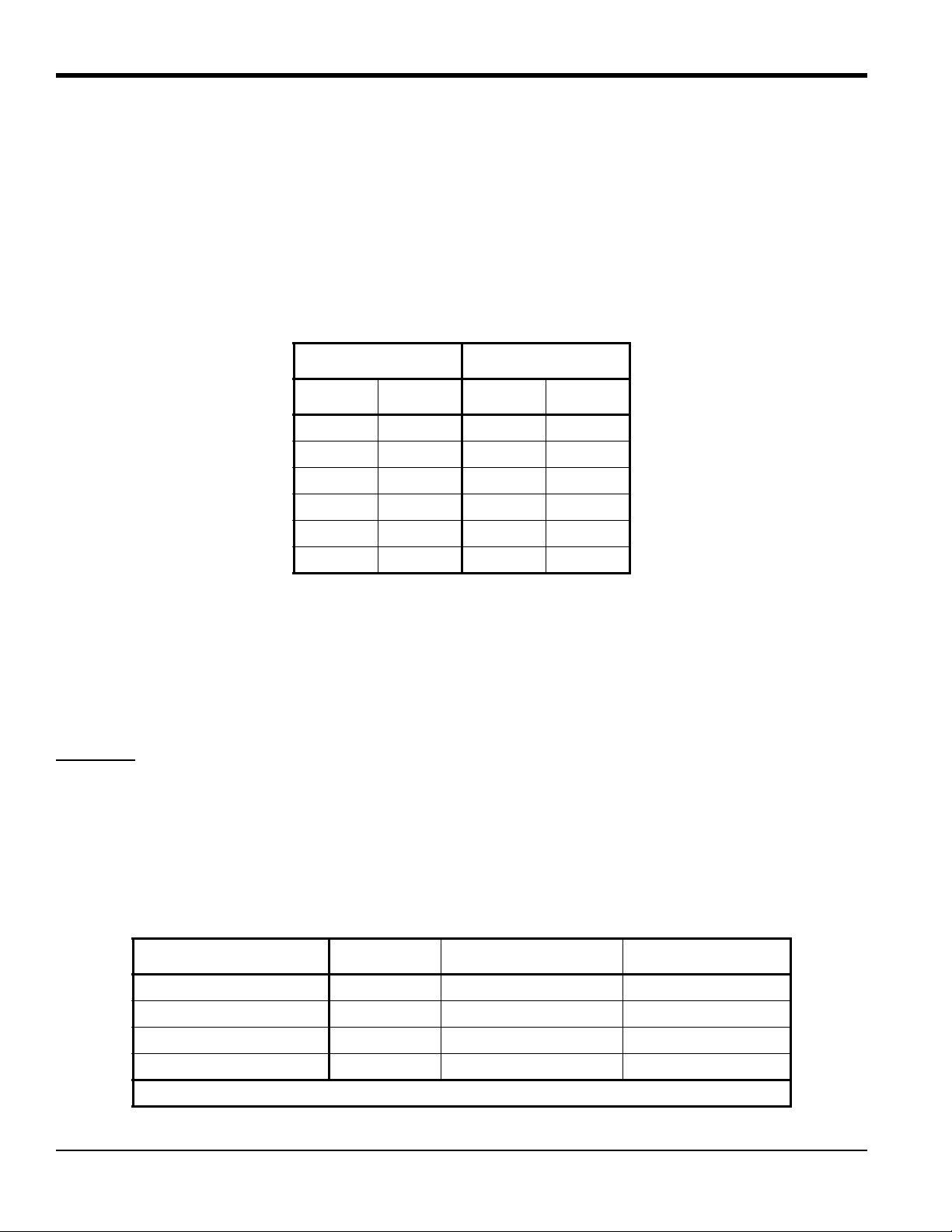
supplied as 18-A WG that can be located up to 1,050 ft (320 m). If you are using your own cable, refer to Table 1 below
for cable requirements.
Table 1: Cable Requirements for TMO2
MAX. CABLE LENGTH CABLE SIZE
Feet Meters AWG Sq. mm
450 130 22 0.35
700 200 20 0.6
1050 320 18 1.0
1700 500 16 1.2
2800 850 14 2.0
4000 1200 12 3.0
For longer cable lengths, consult the factory.
2.3.1b Wiring:
Use the following steps to interconnect the TMO2 to the TMO2D.
1. Route the cable into the TMO2 transmitter through one of the 3/4" conduit holes on the side of the transmitter.
WARNING!
2. Unplug TB1 on the TMO2 transmitter PC board (PCB) by carefully pulling it directly up without bending the
attached to the
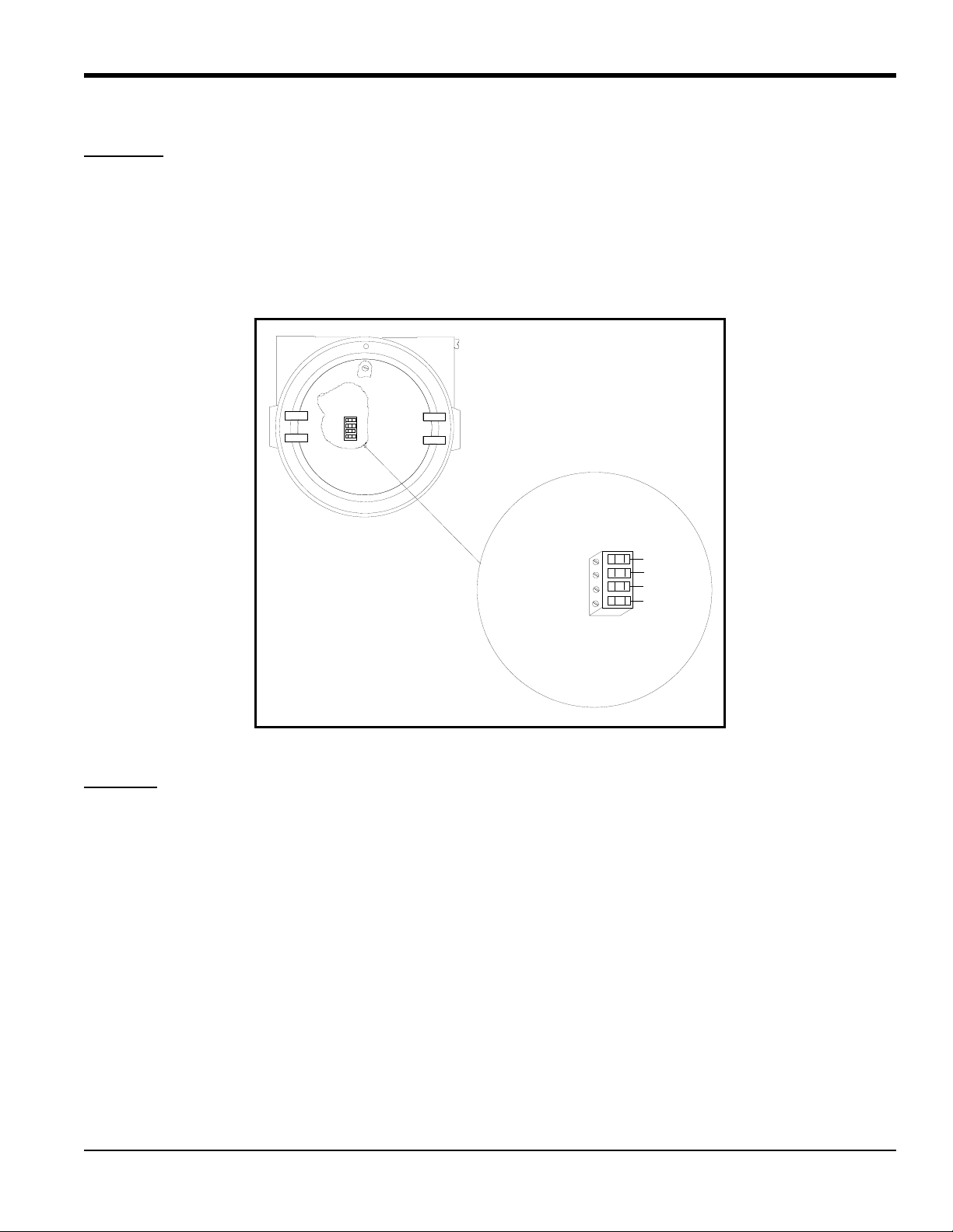
3. Loosen the TB1 side screws and insert the colored wires into the corresponding openings on top of TB1
T
able 2 below for color-coded pin designations, and Figure 1 on page 5 for the TB1 location.
Be sure to plug the unused conduit/cable entry hole on the transmitter, in order to meet
ications and to maintain the appropriate weatherproof or explosion-proof rating.
specif
PCB.
Table 2: Wiring the TMO2 with a 4-Wire Cable
Wire Connections Color TMO2 Transmitter TB1 TMO2D Display TB5
Power +24 VDC Red Pin 1 +24 V
Power Return Black Pin 2 RTN
Oxygen White Pin 3 GAS
. See
pins
External Compensation* Blue or Green Pin 4 COMP
*For external compensation, you must use a 4-wire cable to make this connection
4 TMO2D Digital Display User’s Manual
Page 13
2.3.1b Wiring: (cont.)
2
3
4
1
+24 V/1 AMP 1
Return 2
Gas 3
Comp. 4
Red
Black
White
Green/Blue
Signal Connections
Chapter 2. Installation
WARNING!
Make sure that the +24 VDC wire (red) is connected to terminal TB1-1. Connecting +24 VDC to
any other other terminal could cause bodily harm. It could also cause damage to the TMO2 PCB,
requiring factory repair.
4. Tighten the side screws, and carefully plug TB1 back onto the TMO2 PCB.
5. Connect the other end of the cable in a similar manner to the TMO2D. Refer to Figure 11 on page 17
location.
for TB1
F
igure 1: Wiring Connections to TB1 Block
CAUTION!
Do not make any connections to unassigned or unused terminals.
TMO2D Digital Display User’s Manual 5
Page 14
Chapter 2. Installation
2
3
4
1
+24 V/1 AMP 1
Return 2
Gas 3
Comp. 4
Red
Black
White
Green/Blue
Connect Shield
Signal Connections
2.3.1 TMO2 Transmitter (cont.)
2.3.1c CE Mark Compliance
IMPORTANT: CE Mark compliance is required only for units used in EU countries.
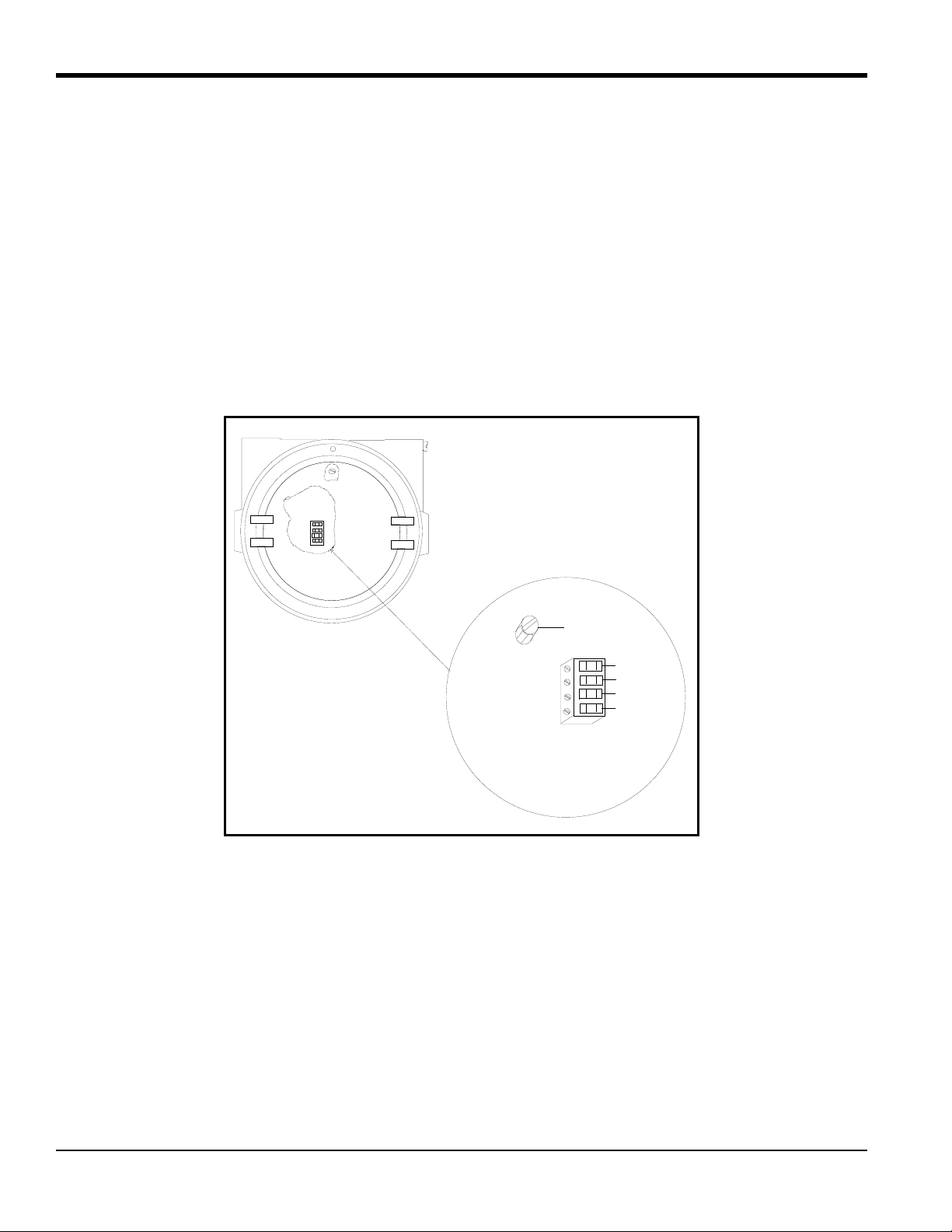
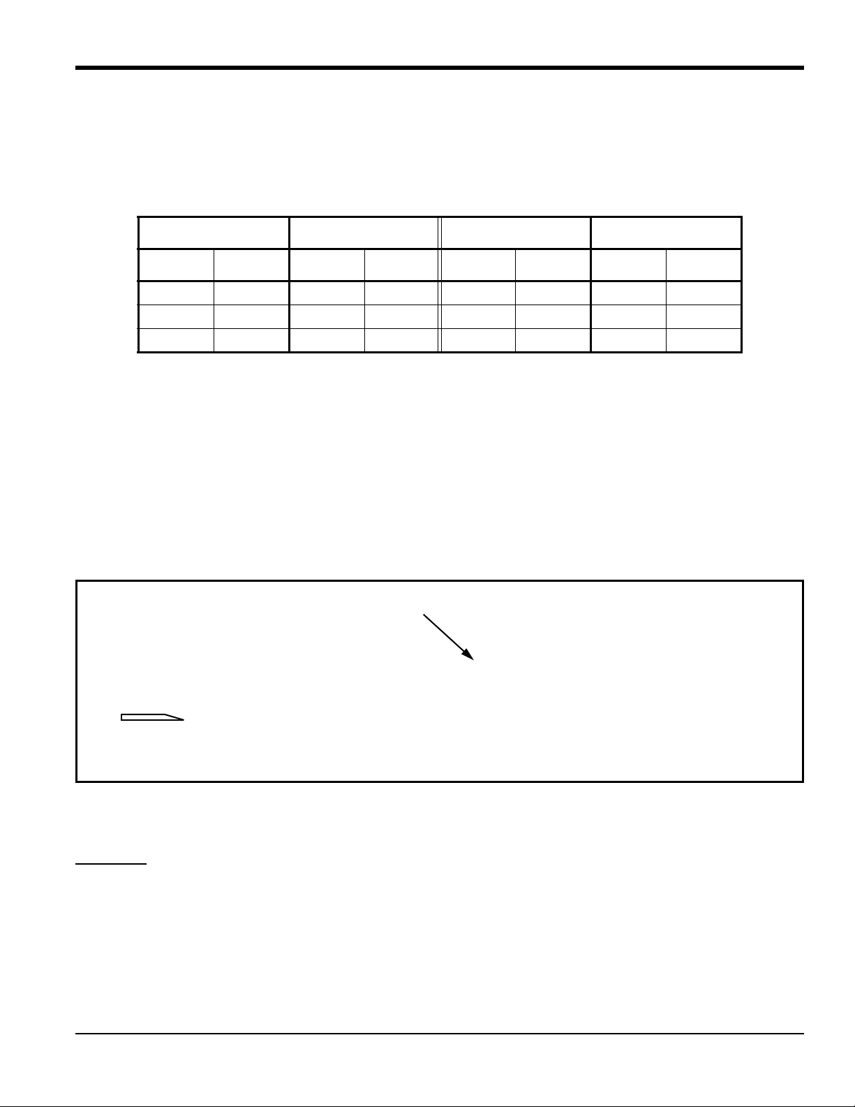
For CE Mark compliance, you must use shielded cable and connect the shield to the stand off as shown in Figure 2
below . After you make all the necessary electrical connections, seal the unused cable entry holes with standard conduit
plugs or their equivalent.
Note: If you make the modifications as discussed here, your unit will comply with the EMC Directive 2004/108/EC.
Note: For CE compliance, the I/O cables must be shielded. The shields are to be grounded within the TMO2D to the
closest location.Shielded cable is not required when installations include metal conduit.
Figure 2: TMO2 Wiring Connections
6 TMO2D Digital Display User’s Manual
Page 15
Chapter 2. Installation
Cable Shield
2.3.2 XMO2 Transmitter
Wiring the XMO2 oxygen transmitter to the TMO2D display requires use of the X4(*) cable, which can support
distances up to 450 ft (130 m). For longer distances, each cable can be supplied as 18-AWG that can be locate d up to
1,050 ft. (320 m). If you are using your own cable, refer to Table 3 below for cable requirements.
Table 3: Cable Requirements for XMO2
MAX. CABLE LENGTH CABLE SIZE MAX. CABLE LENGTH CABLE SIZE
Feet Meters AWG Sq. mm Feet Meters AWG Sq. mm
450 130 22 0.35 1,700 500 16 1.2
700 200 20 0.6 2,800 850 14 2.0
1,050 320 18 1.0 4,000 1,200 12 3.0
For longer cable lengths, consult the factory.
2.3.2a Wiring:
Use the following steps to interconnect the XMO2 to the TMO2D.
1. Route the 4-wire power/analog output cable through a cable gland as shown in Figure 3 below.
2. After terminating the shield as shown, assemble the three gland pieces together and tighten the gland to secure the
cable and the shie
IMPORTANT: The cable shield must be terminated in the cable gland as shown in Figure 3 below.
ld.
Figure 3: Proper Cable Gland Assembly
3. Route the cable into the XMO2 transmitter through one of the 3/4" conduit holes on the side of the transmitter.
WARNING!
Be sure to plug the unused conduit/cable entry hole on the transmitter, in order to meet
ecifications and to maintain the appropriate weatherproof or explosion-proof rating.
sp
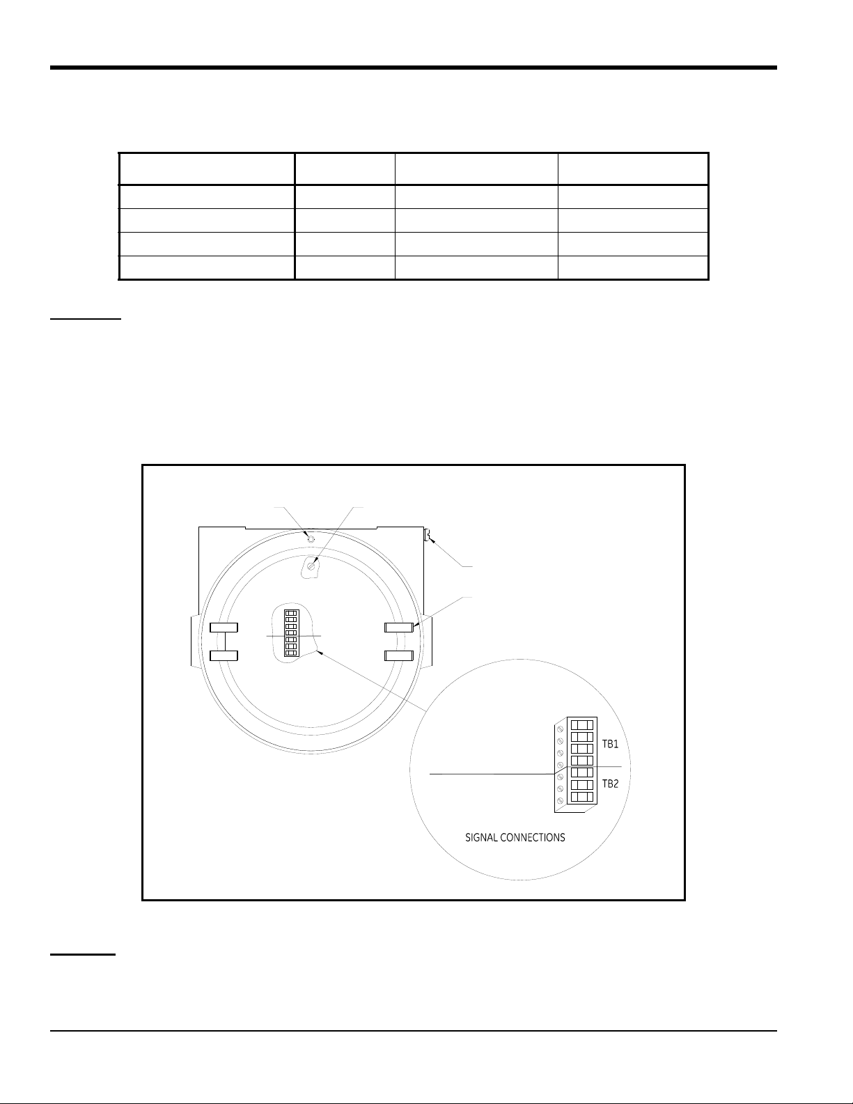
4. Unplug terminal block TB1/TB2 on the XMO2 transmitter PC board (PCB) by carefully pul
without bending the
pins attached to the PCB. (See Figure 4 on page 8.)
5. Loosen the TB1 side screws and insert the colored wires into the corresponding openings on top of TB1
able 4 on page 8 for color-coded pin designations.
T
TMO2D Digital Display User’s Manual 7
ling it directly up
. See
Page 16
Chapter 2. Installation
1
+24VDC Line (red) 1
2
3
4
2
3
–24VDC Return (black)
+4 to 20mA (white)
–4 to 20 mA (green)
RS232 TX (white)
RS232 GND (green)
2
3
4
1
3
External Ground Screw
Cover
Internal Ground Screw
Set Screw
RS232 RX (red) 1
2
2.3.2a Wiring: (cont.)
Wire Connections Color XMO2 Transmitter TB1 TMO2D Display TB5
Power +24 VDC Red Pin 1 +24 V
Power Return Black Pin 2 RTN
+ mA Signal White Pin 3 GAS
–mA Signal Blue or Green Pin 4 RTN
Table 4: Wiring the XMO2 with 4-Wire Cable
WARNING!
Make sure that the +24 VDC wire (red) is connected to terminal TB1-1. Connecting +24 VDC to
any other terminal could cause bodily harm. It could also cause damage to the XMO2 PCB
requiring factory repair.
6. Tighten the side screws, and carefully plug terminal block TB1/TB2 back onto the XMO2 PCB.
7. Connect the other end of the cable in a similar manner to the TMO2D. Refer to Figure 11 on page 17 for th
location.
e TB1
Figur
e 4: Wiring Connections to the XM02 TB1/TB2 Block
CAUTION!
8 TMO2D Digital Display User’s Manual
Do not make any connections to unassigned or unused terminals.
Page 17
Chapter 2. Installation
1
+24VDC Line (red) 1
2
3
4
2
3
–24VDC Return (black)
+4 to 20mA (white)
–4 to 20 mA (green)
RS232 TX (white)
RS232 GND (green)
2
3
4
1
3
External Ground Screw
Cover
Internal Ground Screw
Set Screw
RS232 RX (red) 1
2
2.3.2b CE Mark Compliance
IMPORTANT: CE Mark compliance is required only for units used in EU countries.
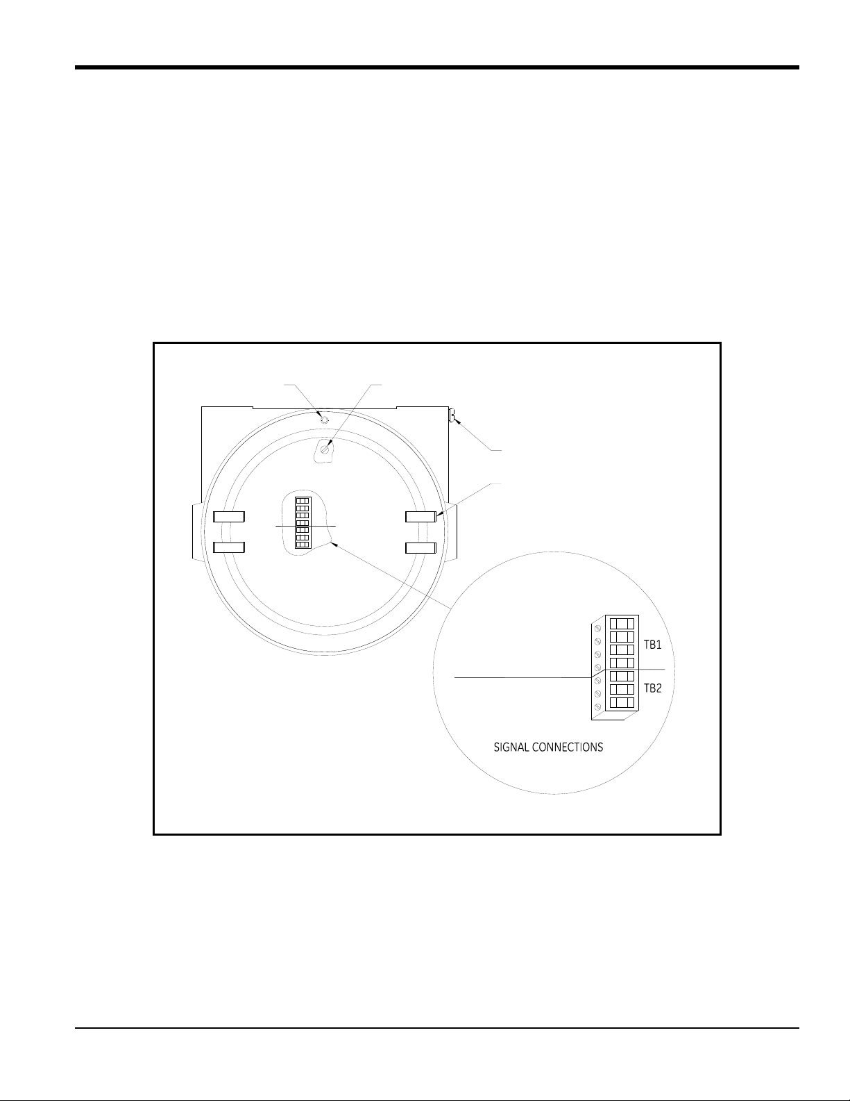
For CE Mark compliance, you must use shielded cable and connect the shiel d to a cable gland (see Figure 3 on page 7).
After you make all the necessary electrical connections, seal the unused cable entry holes with standard conduit plugs
or their equivalent.
Note: If you make the modifications as discussed here, your unit will comply with the EMC Directive 2004/108/EC.
Note: For CE compliance, the I/O cables must be shielded. The shields are to be grounded within the TMO2D to the
closest location. Shielded cable is not required when installations include metal conduit.
Figure 5: XMO2 Wiring Connections
TMO2D Digital Display User’s Manual 9
Page 18
Chapter 2. Installation
2.3.3 TMO2-TC Transmitter
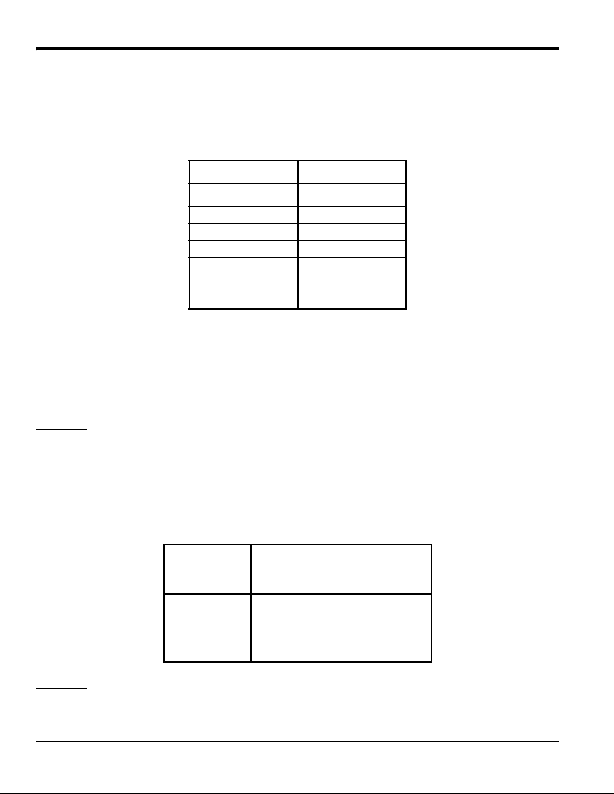
Connecting the TMO2-TC thermal conductivity transmitter to the TMO2D requires use of the X3(*) or Y3(*) cables.
The X3(*) cable can be used for distances up to 450 ft (130 m). For longer distances, each cable can be supplied as
18-AWG that can be located up to 1,050 ft (320 m). If you are using your own cable, refer to Table 5 below fo
requirements.
Table 5: Cable Requirements for TMO2-TC
MAX. CABLE LENGTH CABLE SIZE
Feet Meters AWG Sq. mm
450 130 22 0.35
700 200 20 0.6
1,050 320 18 1.0
1,700 500 16 1.2
2,800 850 14 2.0
4,000 1,200 12 3.0
r cable
For longer cable lengths, consult the factory
.
2.3.3a Wiring:
Use the following steps to interconnect the TMO2-TC to the TMO2D.
1. Route the cable into the TMO2-TC transmitter through one of the 3/4" conduit holes on the side of the transmitter.
WARNING!
2. Unplug TB1 on the TMO2-TC transmitter PC board (PCB) by carefully pulling it directly up without bending
p
ins attached to the PCB. See Figure 6 on page 11.
3. Loosen the TB1 side screws and insert the colored wires into the corresponding openings on top of TB1. Refer
T
able 6 below for color-coded pin designations.
Be sure to plug the unused conduit/cable entry hole on the transmitter, in order to meet
ications and to maintain the appropriate weatherproof or explosion-proof rating.
specif
Table 6: Wiring the TMO2-TC with 3-Wire Cable
Wire
Connections Color
TMO2-TC
Transmitter
TB1
TMO2D
Display
TB5
Power +24 VDC Red Pin 1 +24 V
Power Return Black Pin 2 RTN
+mA Signal White Pin 3 GAS
the
to
No Connection
WARNING!
Make sure that the +24 VDC wire (red) is connected to terminal TB1-1. Connecting +24 VDC to
any other terminal could cause bodily harm. It could also cause damage to the TMO2-TC PCB,
requiring factory repair.
10 TMO2D Digital Display User’s Manual
Page 19
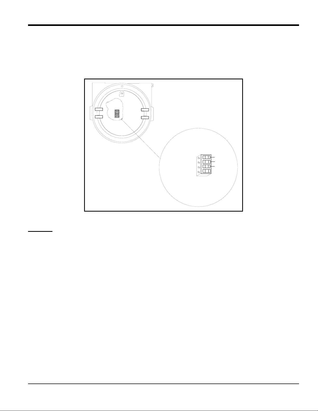
2.3.3a Wiring: (cont.)
2
3
4
1
+24 V/1 AMP 1
Return 2
Oxygen 3
None 4
Red
Black
White
4. Tighten the side screws, and carefully plug TB1 onto the PCB.
Chapter 2. Installation
5. Connect the other end of the cable in a similar manner to the TMO2D. Refer to Figure 11 on page 17
location.
for TB1
F
igure 6: Wiring Connections to TB1 Block
CAUTION!
Do not make any connections to unassigned or unused terminals.
2.3.3b CE Mark Compliance
IMPORTANT: CE Mark compliance is required only for units used in EU countries.
For CE Mark compliance, you must use shielded cable and connect the shield to the stand off as shown in Figure 7 on
page 12. After you make all the necessary electrical connections, seal the unused cable entry holes with standard
conduit plugs or their equivalent.
Note: If you make the modifications as discussed here, your unit will comply with the EMC Directive 2004/108/EC.
Note: For CE compliance, the I/O cables must be shielded. The shields are to be grounded within the TMO2D to the
closest location. Shielded cable is not required when installations include metal conduit.
TMO2D Digital Display User’s Manual 11
Page 20

Chapter 2. Installation
2
3
4
1
+24 V/1 AMP 1
Return 2
Oxygen 3
None 4
Red
Black
White
Connect Shield
2.3.3b CE Mark Compliance (cont.)
Figure 7: TMO2-TC Wiring Connections
2.3.4 XMTC Transmitter
Connecting the XMTC thermal conductivity transmitter to the TMO2D requires use of the X4(*) or Y4(*) cables. The
X4(*) cable can be used for distances up to 450 ft (130 m). For longer distances, each cable can be supplied as
18-AWG that can be located up to 1,050 ft (320 m). If you are using your own cable, refer to Table 7 below fo
requirements.
Table 7: Cable Requirements for XMTC
MAX. CABLE LENGTH CABLE SIZE
Feet Meters AWG Sq. mm
450 130 22 0.35
700 200 20 0.6
1,050 320 18 1.0
1,700 500 16 1.2
2,800 850 14 2.0
4,000 1,200 12 3.0
For longer cable lengths, consult the factory
.
r cable
12 TMO2D Digital Display User’s Manual
Page 21
Chapter 2. Installation
2
3
4
1
+4 to 20 mA (white) 3
–4 to 20 mA (green) 4
RS232 TX (white) 2
RS232 GND (green) 3
TB1
2
3
+24 VDC Line (red) 1
–24 VDC Return (blk) 2
RS232 RX (red) 1
TB2
1
Signal Connections
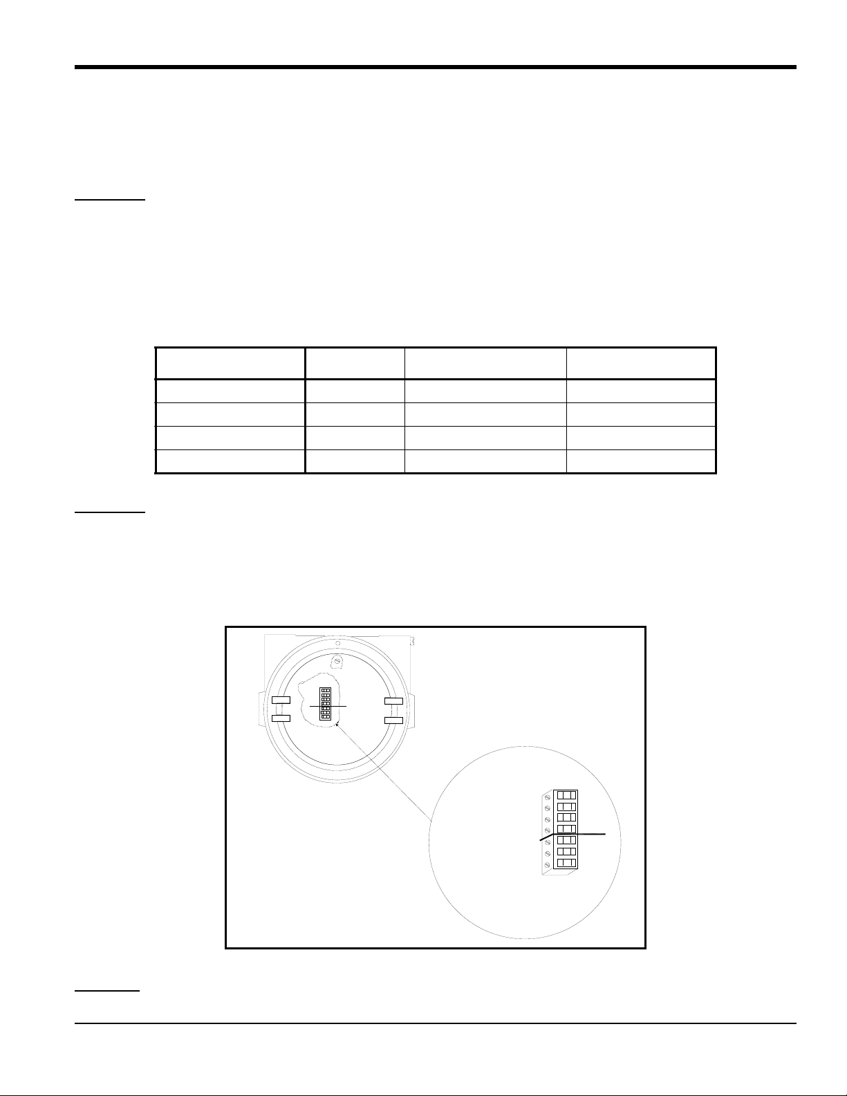
2.3.4a Wiring:
Use the following steps to interconnect the XMTC to the TMO2D.
1. Route the cable into the XMTC transmitter through one of the 3/4" conduit holes on the side of the transmitter.
WARNING!
2. Unplug TB1 on the XMTC transmitter PC board (PCB) by carefully pulling it directly up
attached to the
Be sure to plug the unused conduit/cable entry hole on the transmitter, in order to meet
ecifications and to maintain the appropriate weatherproof or explosion-proof rating.
sp
without bending the pins
PCB. See Figure 8 below.
3. Loosen the TB1 side screws and insert the colored wires into the corresponding openings on top of TB1. Refer
able 8 below for color-coded pin designations.
T
Table 8: Wiring the XMTC with 4-Wire Cable
Wire Connections Color XMTC Transmitter TB1 TMO2D Display TB5
Power +24 VDC Red Pin 1 +24 V
Power Return Black Pin 2 RTN
+mA Signal White Pin 3 GAS
–mA Signal Blue or Green Pin 4 RTN
WARNING!
Make sure that the +24 VDC wire (red) is connected to terminal TB1-1. Connecting +24 VDC to
any other terminal could cause bodily harm. It could also cause damage to the XMTC PCB,
requiring factory repair.
4. Tighten the side screws, and carefully plug TB1 back onto the XMTC PCB.
to
5. Connect the other end of the cable to the TMO2D. Refer to Figure 11 on page 17 for TB1 location.
CAUTION!
TMO2D Digital Display User’s Manual 13
Do not make any connections to unassigned or unused terminals.
Figure 8: Wiring Connections to TB1 Block
Page 22
Chapter 2. Installation
2
3
4
1
+4 to 20 mA (white) 3
–4 to 20 mA (green) 4
RS232 TX (white) 2
RS232 GND (green) 3
TB1
2
3
+24 VDC Line (red) 1
–24 VDC Return (blk) 2
RS232 RX (red) 1
TB2
1
Signal Connections
Connect Shield
2.3.4b CE Mark Compliance
IMPORTANT: CE Mark compliance is required only for units used in EU countries.
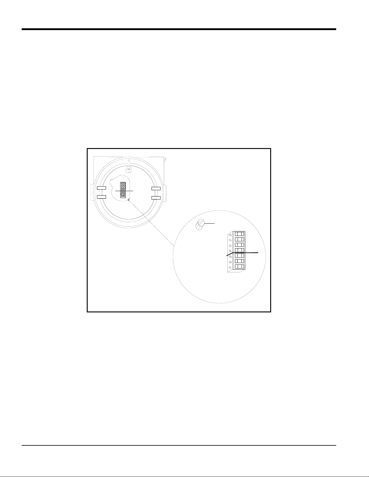
For CE Mark compliance, you must use shielded cable and connect the shield to the stand off as shown in Figure 9
below . After you make all the necessary electrical connections, seal the unused cable entry holes with standard conduit
plugs or their equivalent.
Note: If you make the modifications as discussed here, your unit will comply with the EMC Directive 2004/108/EC.
Note: For CE compliance, the I/O cables must be shielded. The shields are to be grounded within the TMO2D to the
closest location. Shielded cable is not required when installations include metal conduit.
Figure 9: XMTC Wiring Connections
14 TMO2D Digital Display User’s Manual
Page 23
Chapter 2. Installation
J8
(Pin 1)
Pin 2 = Transmit (from)
Pin 3 = Receive (to)
Pin 7 = Return (ground)
(Pin 14)
2.3.5 RS-232C Serial Port
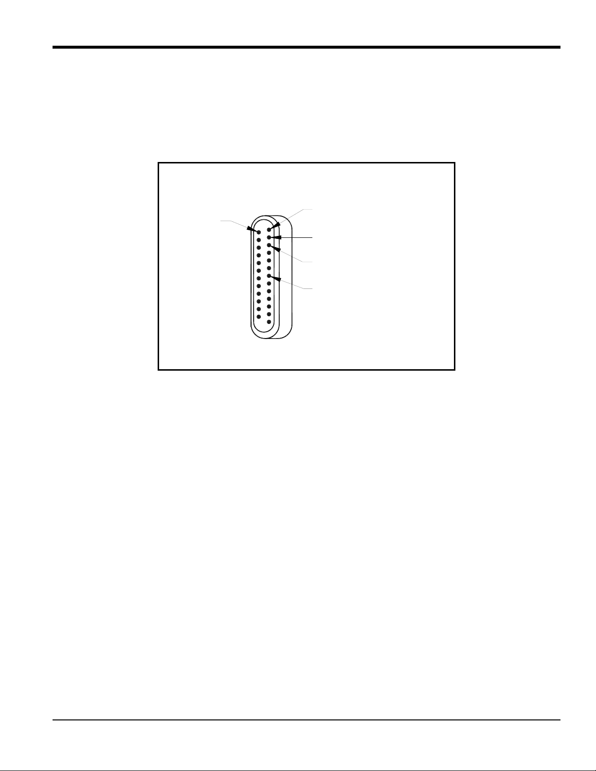
The TMO2D has a bi-directional, industry-standard RS-232C serial port (#J8) that can be connected to a terminal or
computer that supports the RS-232C protocol. Connect the RS-232C from the computer or terminal to the rear of the
TMO2D using a 25-pin connector. (See Figure 10 below for the RS-232 wiring pin connections, and Chapter 3 for the
corresponding key chart.)
Figure 10: Display RS-232C Serial Port Connections
2.4 Wiring Other Components to the TMO2D Display
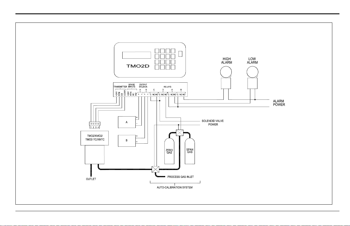
If desired, the TMO2D Analyzer can be wired to 4-20mA outputs, AutoCal systems, and alarms. Figure 11 on page 17
shows the possible wiring connections.
TMO2D Digital Display User’s Manual 15
Page 24

Chapter 2. Installation
16 TMO2D Digital Display User’s Manual
Page 25
Chapter 2. Installation
Figure 11: TMO2D Transmitter and Display Wiring Options (ref. dwg #701-030, sht 2)
TMO2D Digital Display User’s Manual 17
Page 26
Chapter 2. Installation
TMO2D Digital Display User’s Manual 18
Page 27

Chapter 3. Operation
Chapter 3. Operation
3.1 Introduction
This chapter provides information on operating the TMO2D Display. If you have not already done so, please read
Chapter 2, Installation, for details on mounting and wiring the TMO2D display.
WARNING!
To ensure safe operation of the TMO2D, you must install and operate it as described in this
manual. In addition, be sure to follow all applicable safety codes and regulations for installing
electrical equipment in your area. All installation procedures should be performed by trained
service personnel.
3.2 Powering Up
CAUTION! The interconnecting wiring between the transmitter and display must be completed before
powering up.
To power up the benchtop TMO2D, press the red power key to the right of the display. Other TMO2D models have no
power switch, and begin operating when the external power to which they have been connected has been turned on.
3.3 The User Interface
The electronic display unit contains a 2-line by 24-character backlit Liquid Crystal Display screen (LCD). On
power-up, the display unit tests its memory (RAM), then searches for valid calibration data from the display as well as
input from the transmitter.
If calibration data has already been entered into the display, the unit immediately begins taking measurements from the
transmitter and the LCD begins displaying the gas concentration.
If valid calibration data has not been entered and stored in the display, or if the transmitter is not hooked up to the
display , the LCD will display erroneou s readings. (Chapter 4, Pr ogramming the TMO2D Display, explains how to enter
data into the display.)
The TMO2D is operated using the keypad. To facilitate operation, you should familiarize yourself with the display and
keypad functions.
3.3.1 The LCD Display
The first line of the LCD screen displays the current measurement or menu title and a real-time clock. The second line
of the LCD screen displays the measured data on the left and the current alarm condition on the right.
Note: The LCD contains an electroluminescent (EL) panel to enhance readability of the screen during operation. To
activate the EL panel, press any key except the [NO] key.
TMO2D Digital Display User’s Manual 19
Page 28
Chapter 3. Operation
TMO2D
Panametrics Display
and Control Module
–
7
4
1
0
8
5
2
•
9
63No
Yes
Power
On
3.3.2 The Keypad
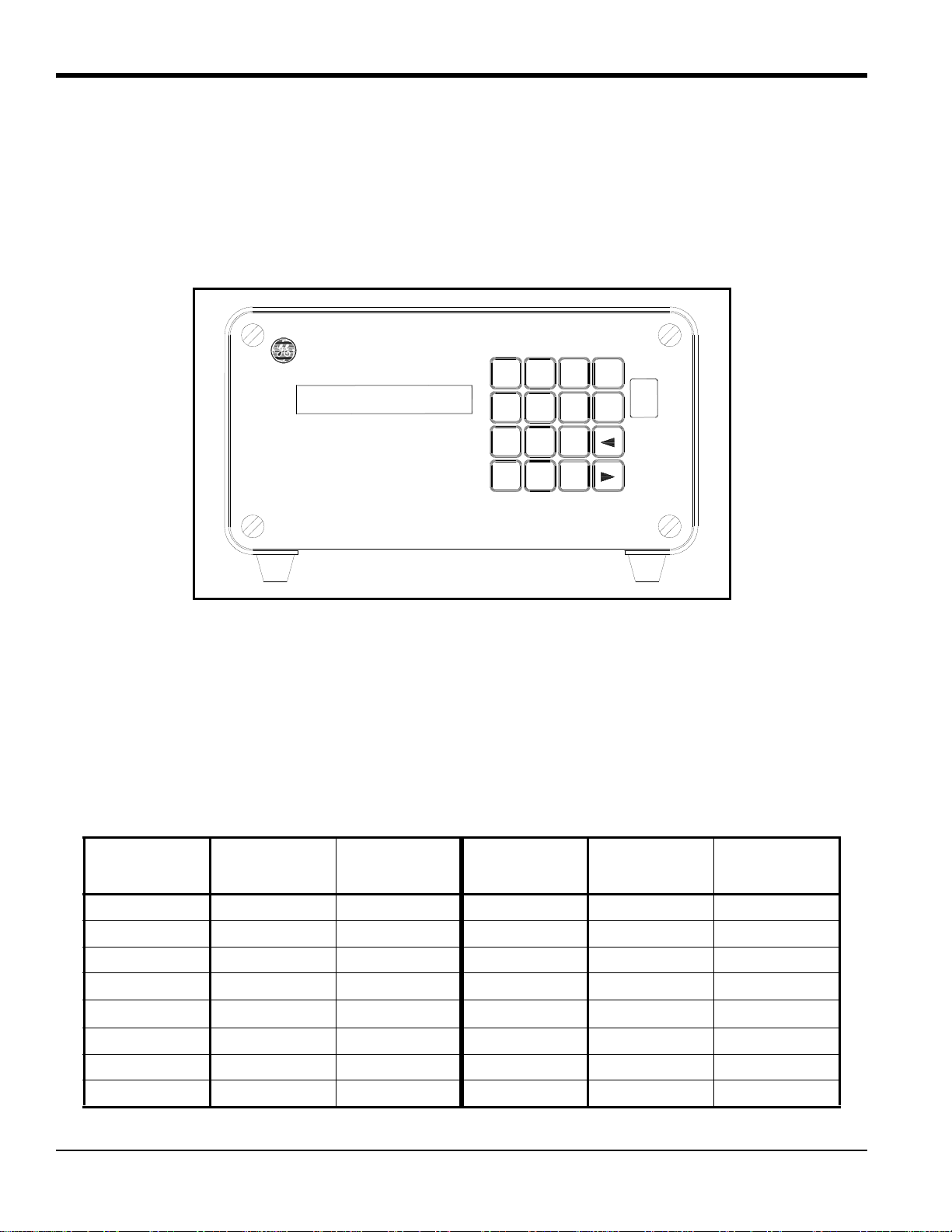
For operational purposes, the keypad (Figure 12 below) includes digits 0-9, a minus sign, a decimal point, and four
special operations keys:
• [YES] • [NO] • [] • []
Note: For details on how to use the keypad to program the display, see Chapter 4.
Figure 12: The TMO2D Display
3.4 RS-232C Serial Port
The TMO2D contains a bidirectional, industry-standard RS-232C serial port which can be connected to a terminal or
computer that supports the RS-232C protocol (see The Outputs Menu on page 30.)
All keypad and most display operations can be performed remotely through this serial port.
Table 9 below lists terminal/computer keys and how they correspond to the ke ys on the Display keypad.
Table 9: RS-232C Serial Port Corresponding Keys
TMO2D
Keypad ASCII
0 030 0 8 038 8
1 031 1 9 039 9
2 032 2 008 BACKSPACE
3 033 3 020 SPACE
4 034 4
5 035 5 – 02D "–"
6 036 6 YES 00D ENTER
7 037 7 NO 01B ESCAPE
20 TMO2D Digital Display User’s Manual
Computer
Keyboard
TMO2D
Keypad ASCII
•
02E "."
Computer
Keyboard
Page 29

Chapter 4. Basic Programming
Chapter 4. Basic Programming
4.1 Introduction
The TMO2D display contains an interactive, user-friendly program that enables the user to change operating
parameters as desired.
This user program has six main menus. Use the front panel keypad and display to check or change the settings for
current operating parameters. The TMO2D stores data in memory and will retain it for several years if the main power
is lost. New data overrides any previously entered data.
The user program consists of six main menus:
• Setup
• Outputs
• Relays
• Tests
• Calibration
• System Log
Note: The TMO2D can function as a display package for a variety of GE transmitters. As an example, this chapter
describes TMO2D programming when the TMO2D is used with a TMO2 or XMO2 oxygen transmitter.
4.2 Entering Data into the User Program
To enter data into the user program or to check previously entered values, enter the Menu Mode. When the power is
turned on, the TMO2D enters the Operate Mode. To enter the Menu Mode:
1. Press the [NO] key.
2. Key in the code [1] [2] [3]. The TMO2D will display an asterisk (*) after you enter each digit.
If an incorrect code is entered or a non-numeric ([YES]/[NO] or arrow) key is pressed rather than 1 2 3, the LCD will
automatically resume displaying data, and you must press [NO] to re-attempt the code. Once all three digits have been
entered correctly, the display will cease collecting data and the LCD will switch to Menu Mode.
The LCD screen now displays the Setup Menu, the first of the six main menus. At this display, press [YES] to enter this
menu, or [NO] to scroll to the next menu. Pressing [NO] repeatedly scrolls through all six main menus.
Note: The first six options are main menus, while the RESUME prompt enables users to exit the Menu Mode and
return to Operate Mode.
TMO2D Digital Display User’s Manual 21
Page 30
Chapter 4. Basic Programming
4.2.1 Key Functions
The [YES] key enables you to confirm numeric entries or to select a displayed menu option.
The [NO] key enables you to clear a numeric entry or to scroll forward through the menu options.
The [] key has two functions:
• It serves as a backspace key during numeric entry. At each press of [], the display erases the last digit on the right
of the entry.
• It also enables you to step backward through a list of menu options.
The [] key enables you to scroll forward through the menu options; it is equivalent to pressing the [NO] key in the
Menu Mode.
4.3 Programming the TMO2D Using the Display
This section briefly explains display and menu navigation, and then takes you step-by-step through the programming
procedure.
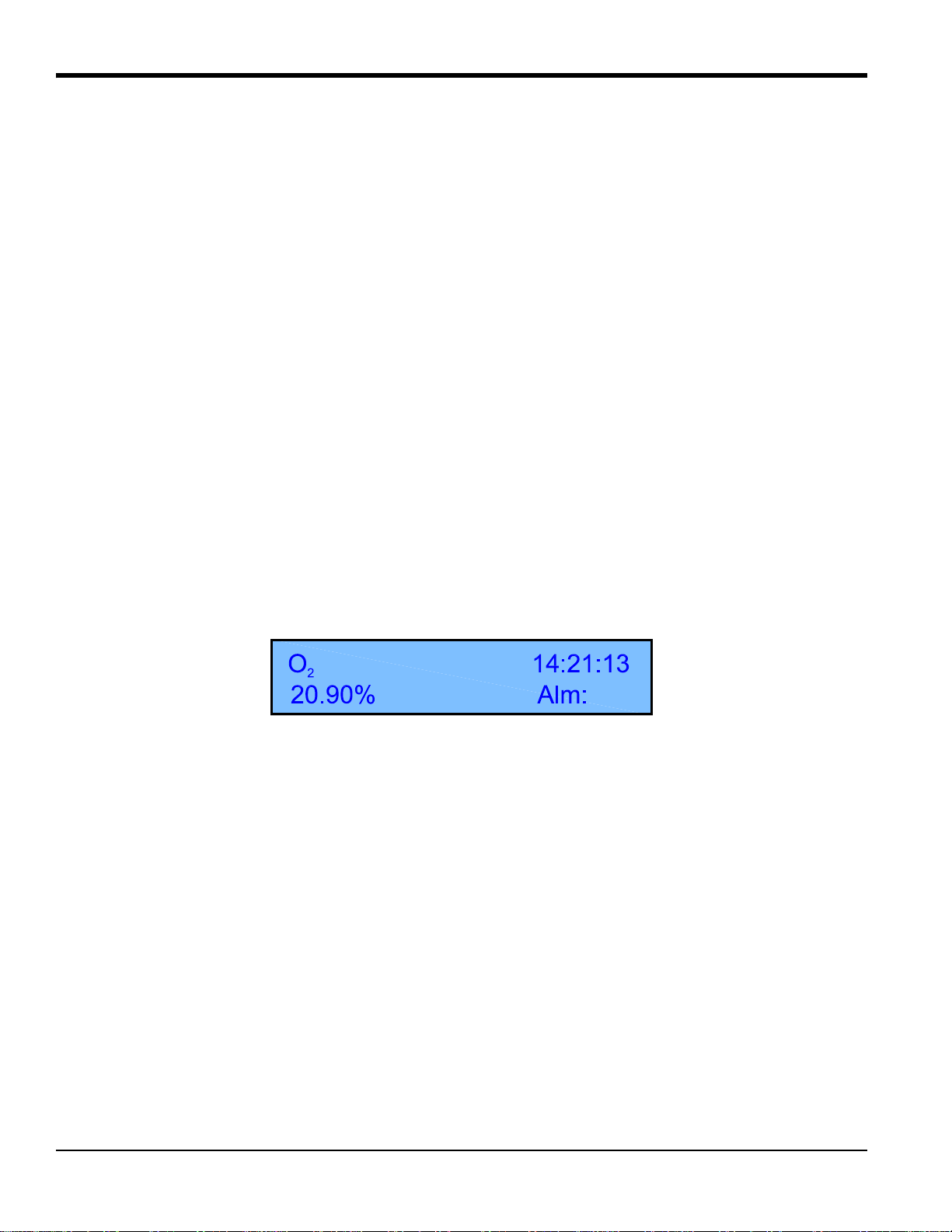
4.3.1 Display Navigation
On power-up, the first line of the LCD screen contains the current measurement parameter and a real-time clock. The
second line of the LCD contains the measured data on the left and the current alarm condition on the right (see
Figure 13 below).
Figure 13: TMO2D Display
While displaying the gas concentration, the display will ignore all keys except the [NO] key. If you press [NO], the
LCD will begin displaying Enter Code: and you must enter the program entry code ([1] [2] [3]). During code entry, the
display continues to update the data display, alarm status, and recorder output.
22 TMO2D Digital Display User’s Manual
Page 31

Chapter 4. Basic Programming
4.3.2 Menu Navigation
After you enter the passcode, the LCD switches to Menu Mode, which enables you to program the display, setting
parameters and calibration data as well as performing relay and output tests. While in Menu Mode, the display
suspends data collection, and relay status and outputs hold their current va lues.
In Menu Mode, the first line of the LCD shows the title of the current menu in capital letters. The second line displays
the current menu options.
Enter data in the Menu Mode through the [YES]/[NO] and Selector ([] and []) keys. Pressing [YES] selects the
displayed option, while pressing [NO] skips that option and displays the next option in the list. The Selector keys
enable users to choose between two or three possible options in the menu.
Note: The menu lists are circular; skipping over the last option in the list returns you to the first option in the list.
The following sections describe the programming procedure and menu navigation in detail, one menu at a time.
(Appendix B supplies flow diagrams of each menu.)
4.4 The Setup Menu
The Setup Menu contains eight submenus:
• Set Time?
• Set Date?
• Set Gas/Units/Scaling?
• Set Backlight?
• Set Contrast?
• Set Display?
• Set Communications?
• Set Error Handling?
These submenus allow you to alter operating parameters. Once entered, these values remain in the display memory
until you change them. (Appendix B offers a flow diagram of the Setup Menu in Figure 26 on page 79.)
TMO2D Digital Display User’s Manual 23
Page 32
Chapter 4. Basic Programming
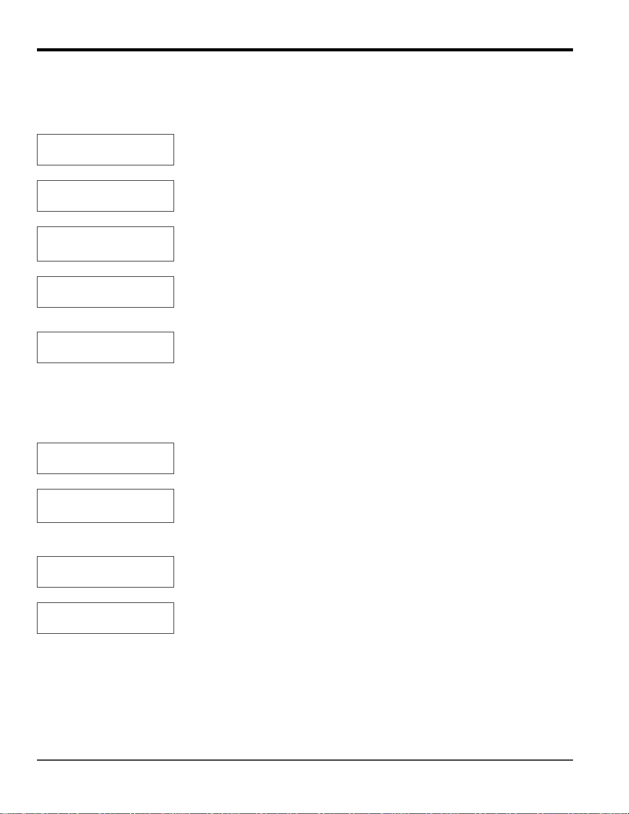
4.4.1 Set Time?
After you enter the Setup Menu, Set Time? enables you to set the current time in 24-hour format. For example, to enter
1:15 pm (13.15 in 24-hour time):
MAIN MENU
Setup?
SETUP MENU
Set Time?
Enter 24 hour time:
HH.MM [XX.XX]: 13.15
Enter 24 hour time:
HH.MM [13.15]:
SETUP MENU
Set Time?
Press [YES] to enter the Setup Menu.
Press [YES] to set the time.
Use the numeric keys to enter a 1, 3, . , 1 and 5. (The X’ s represent the previous time
entered.)
Press [YES] to confirm the entry. Press [YES] again to exit.
Press [NO] to proceed to the next submenu.
4.4.2 Set Date?
The Set Date? submenu is used to set the current date in USA (month, day, year) format. For example, to enter
February 24, 2002:
SETUP MENU
Set Date?
Enter Date (MM.DD.YY):
[XX.XX.XX]:2.24.02
Press [YES] to set the date.
Use the numeric keys to enter a 2, 24 and 02. (The X’s represent the previous date
entered.)
Note: A period (.) must be used to separate the numbers.
Enter Date (MM.DD.YY):
[2.24.02]
SETUP MENU
Set Date?
Press [YES] to confirm the entry, and [YES] again to exit.
Press [NO] to proceed to the next submenu.
24 TMO2D Digital Display User’s Manual
Page 33
Chapter 4. Basic Programming
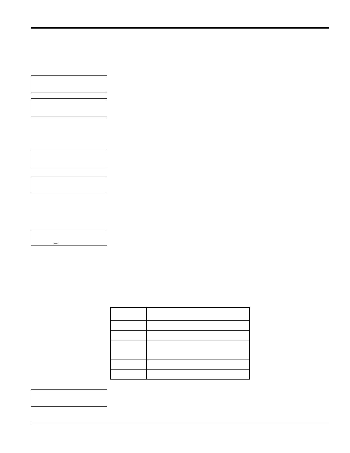
4.4.3 Set Gas/Units/Scaling?
The Set Gas/Units/Scaling? submenu enables you to program the gas label to be displayed, the measurement units in
ppm or %, the input scale (if used with an O2X1), and the measurement units and input range for the input gas.
SETUP MENU
Set Gas/Units/Scaling?
Select Gas Units
percent [PPM]
Press [YES] to set the input gas, units and scale.
Use the [NO] or arrow keys to move the brackets to the desired units. Press [YES] to
confirm the entry.
• If you select percent, the program goes to the “Select Input Gas” window.
• If you select PPM, an additional window appears.
Input Range Maximum ppm:
10 [100] 1,000 10,000
Select Input Gas:
[units]O2
‰
If you have selected one of the five preprogrammed gases, the program returns to the Set Gas/Units/Scaling? submenu.
However, if you have selected OTHER, the TMO2D asks for a gas label. A specific label can contain up to 8 characters.
Gas Label: [ ]
@ABCDEFGHIJKLM[NO]
Use the [NO] or arrow keys to move the brackets to the desired entry. Press [YES] to
confirm the entry.
Use the [NO] or arrow keys to move the brackets to the desired entry. The program
offers six choices: O2, H2, N2, SO2, CO2 and OTHER. Press [YES] to confirm the
entry.
Use the arrow keys or the keypad numbers (see Table 10 below) to move the cursor
to the desired character in the list. When you have reached the desired character,
press the [YES] key to add it to the label. Repeat this procedure to complete the
entire label. If you need to change any characters, use the [–] key on the keypad to
move the cursor to the desired position in the label; then use the arrow keys to select
a new character from the list. When you have finished editing the label, press the [.]
key on the keypad. If you need to delete extra characters in the label, use the [–] key
on the keypad to move the cursor to the character, and hit the [NO] key to delete it.
Table 10: Character Set for Gas Labels
Entry Line Characters
[1] ! “ # $ % & ‘ ( ) * + , – . /
[2]
0 1 2 3 4 5 6 7 8 9 : ; < = > ?
[3] @ A B C D E F G H I J K L M N O
[4] P Q R S T U V W X Y Z [
¥ ] ^ _
[5] \ a b c d e f g h i j k l m n o
[6] p q r s t u v w x y z { 2 L H x
SETUP MENU
Set Gas/Units/Scaling?
TMO2D Digital Display User’s Manual 25
Press [NO] to proceed to the next submenu.
Page 34
Chapter 4. Basic Programming
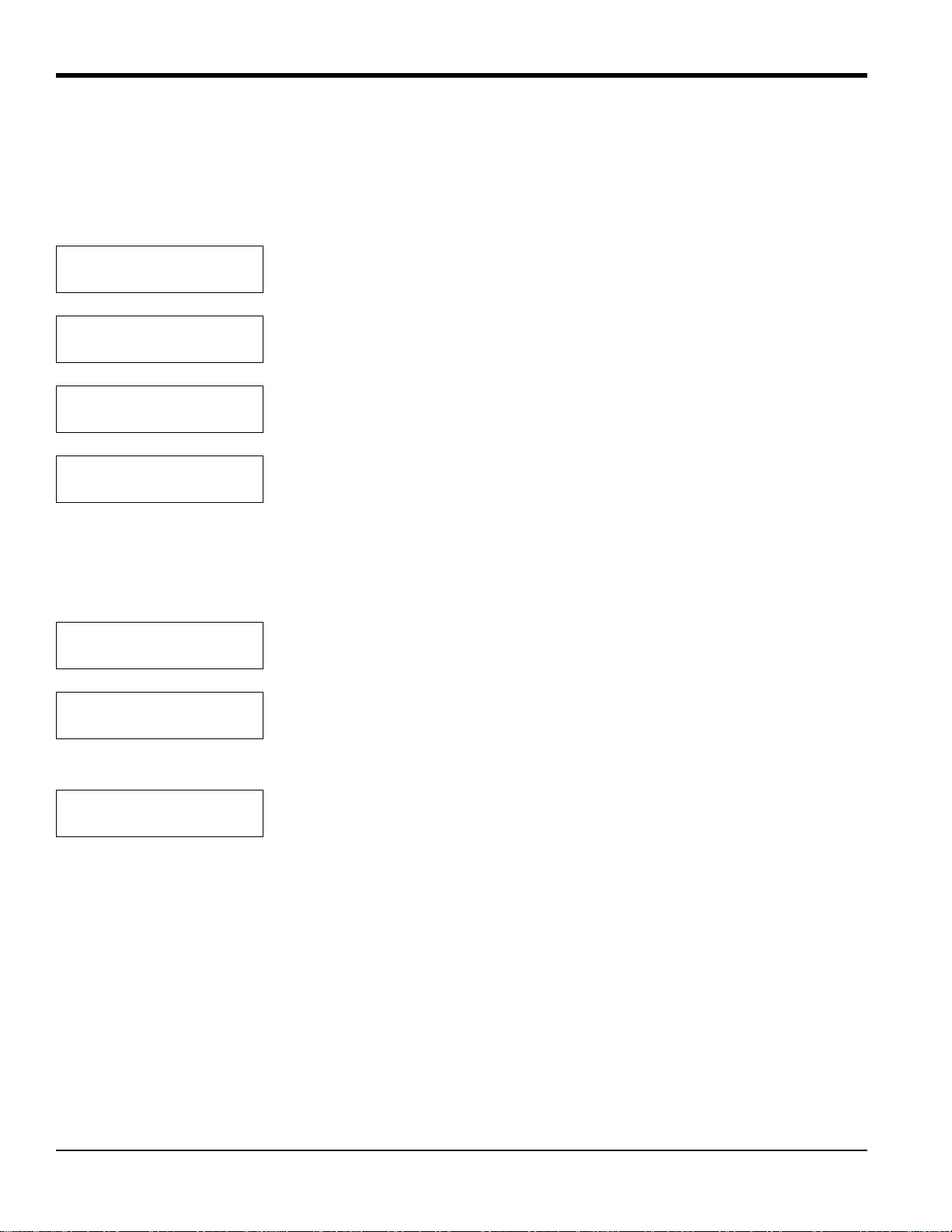
4.4.4 Set Backlight?
The LCD contains an electroluminescent (EL) panel to enhance the readability of the screen in dim light. EL panels
have a finite life span, and eventually dim with use. To maintain the life of the EL backlight, the display will
automatically turn the backlight off after a predetermined time period. The Backlight time-out period can be set from
(but never on) 0 to 60 minutes. The default time-out is three minutes. Example, to set the backlight time to 10 minutes:
SETUP MENU
Set Backlight?
SETUP MENU
Remain ON (min) [X]: 10
SETUP MENU
Remain ON (min) [10]:
SETUP MENU
Set Backlight?
Press [YES] to set the backlight.
Use the numeric keys to enter 10. (The X’s represent the previous time entered.)
Press [YES] to confirm the entry, and [YES] again to exit.
Press [NO] to proceed to the next submenu.
4.4.5 Set Contrast?
The Set Contrast? submenu enables you to adjust how vividly the LCD appears in the prevailing light. To adjust the
contrast for maximum visibility:
SETUP MENU
Set Contrast?
Adjust LCD Contrast
[INCR] decr done
Press [YES] to set the contrast.
Use [NO] or the right arrow key to scroll through the three selections. Press [YES] at
the INCR or DECR selections, and continue pressing [YES] until you have adjusted
the contrast to your conditions. Then select DONE and press [YES] to exit.
SETUP MENU
Set Contrast?
26 TMO2D Digital Display User’s Manual
Press [NO] to proceed to the next submenu.
Page 35
Chapter 4. Basic Programming
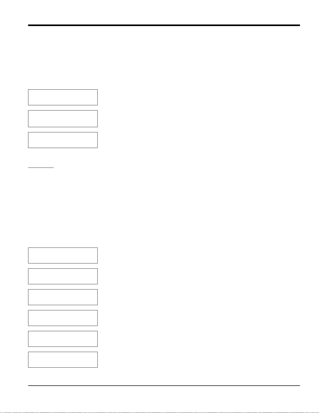
4.4.6 Set Display?
Although this feature is not commonly used, the TMO2D, when used with the TMO2, can display compensation values
for pressure or the percentage of background gas. For the analyzer to display these values, the TMO2 must include
external compensation. In addition, you must enable either background or pressure compensation through the
Calibration menu (see page 37) in the Select Compensation submenu (page 38). If neither pressure nor background
compensation is enabled, a “Comp not enabled” message will appear.
SETUP MENU
Set Display?
Display Compensation
[[NO]NE] pres bkgd
SETUP MENU
Set Display?
Press [YES] to set the display.
Use the [NO] or arrow keys to move the brackets to the desired entry. Press [YES] to
confirm the entry and exit.
Press [NO] to proceed to the next submenu.
4.4.7 Set Communications?
Baud Rate: The display contains a bi-directional, industry-standard RS-232C serial port that enables users to operate
the instrument remotely with a keypad or computer that supports the RS-232C protoc ol. All keypad operations, and
most display operations, can be performed remotely through this port. (See page 20 for operation instructions.)
The display supports the communication rates of 9600, 4800, 2400, 1200 and 300 baud. The default setting is 9600
baud. Other parameters are fixed at 8 bits, 1 stop bit, no parity.
Note: The 300-baud set ting is provided for compatibility with older equipment; however , the use of 300 baud greatly
limits the computation speed of the TMO2D, and its use is not recommended.
The Set Communications? submenu enables you to select both the baud rate and the update rate, when they
communicate with the TMO2D through the RS-232 port.
SETUP MENU
Set Communications?
SET COMMUNICATIONS
Set Baud Rate?
SELECT BAUD RATE
9600 baud?
SELECT BAUD RATE
4800 baud?
SELECT BAUD RATE
2400 baud?
SELECT BAUD RATE
1200 baud?
TMO2D Digital Display User’s Manual 27
Press [YES] to enter the submenu.
Press [YES] to enter the baud rate.
Use the [NO] or arrow keys to scroll through the choices.
Page 36
Chapter 4. Basic Programming
4.4.7 Set Communications? (cont.)
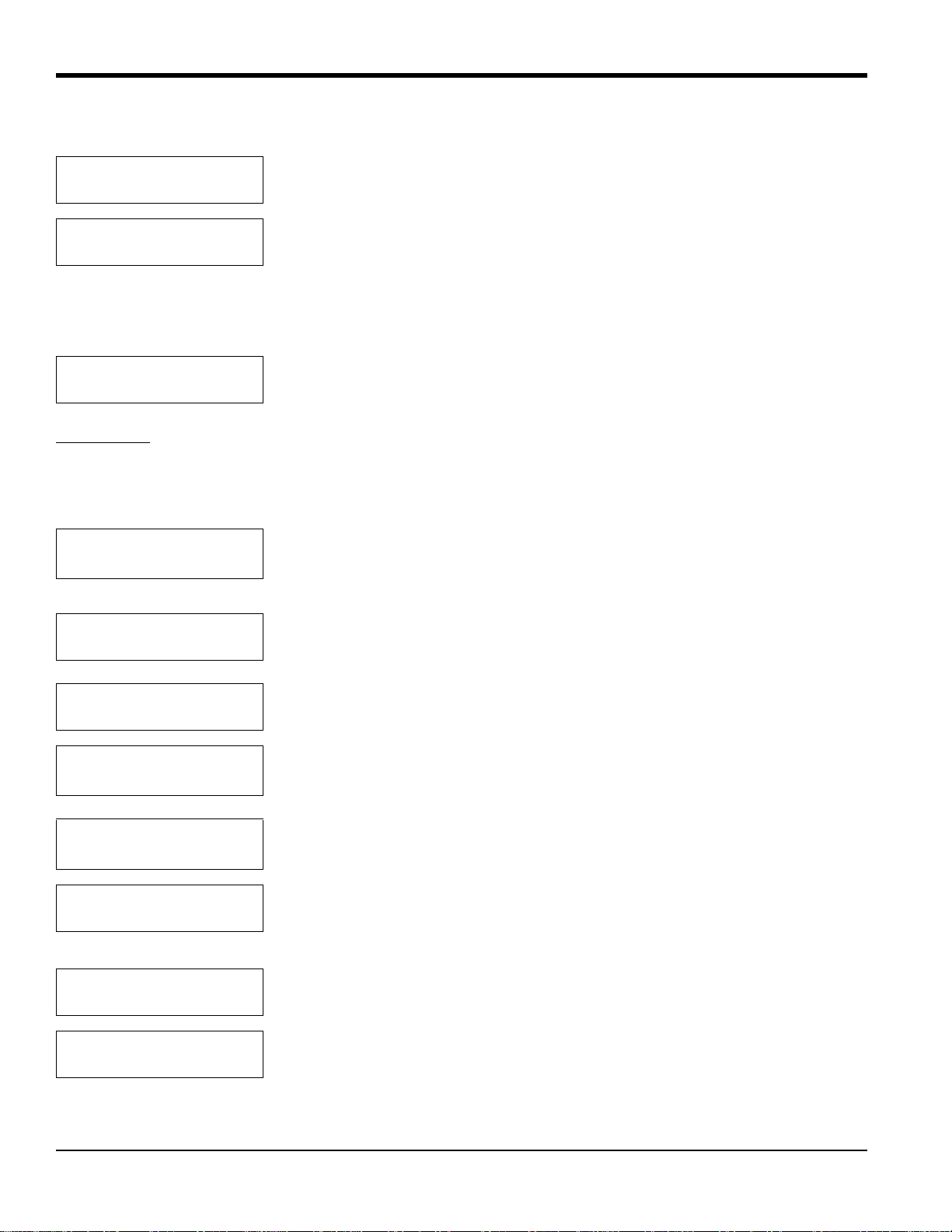
SELECT BAUD RATE
300 baud?
SET COMMUNICATIONS
Set Baud Rate?
Press [YES] to select the desired baud rate and exit.
Press [NO] to proceed to the next submenu.
Note: The baud rate can be changed using a terminal connected to the RS-232C port. However, this is not
recommended, as the TMO2D will immediately change to the new baud rate. Display and keyboar d operation
will not be correct until the baud rate of the terminal is changed to match the new baud rate set in the TMO2D.
SET COMMUNICATIONS
Set Update Rate?
Update Rate:
This option is used to change the interval at which data goes to the serial port. The current data interval
Press [YES] to set the update rate.
will appear in brackets, and users can enter a new data interval.
Data intervals range from 0 to 300 seconds. A data rate of zero will prevent data from passing to the serial port.
SET COMMUNICATIONS
Data Interval [X]: 180
For example, enter 1, 8 and 0 for a 180 sec (3 min) interval. (The X represents the
previously entered data interval.).
SET COMMUNICATIONS
Data Interval [180]:
SET COMMUNICATIONS
Set Update Rate?
SET COMMUNICATIONS
Set Time Stamp?
Print Time Stamp:
YES [NO]
SET COMMUNICATIONS
Set Time Stamp?
SET COMMUNICATIONS
Done?
SETUP Menu
Set Communications?
Press [YES] to confirm the entry, and [YES] again to exit.
Press [NO] to proceed to the next submenu.
Press [YES] to determine if you want the record printed with a time stamp. If you
select this option, the date and time for each data point will go to the serial port.
Use the [NO] or arrow keys to indicate whether a time stamp will be printed. Then
press [YES] to confirm the selection.
Press [NO] to proceed to the next submenu.
Press [YES] to return to the main Setup Menu.
Press [NO] to proceed to the next submenu.
28 TMO2D Digital Display User’s Manual
Page 37
Chapter 4. Basic Programming
4.4.8 Set Error Handling?
The Set Error Handling? submenu enables the TMO2D to handle inputs it receives that are outside its measurement
range. Based on directions it receives, the TMO2D can show the errors on the display and force an output high or low.
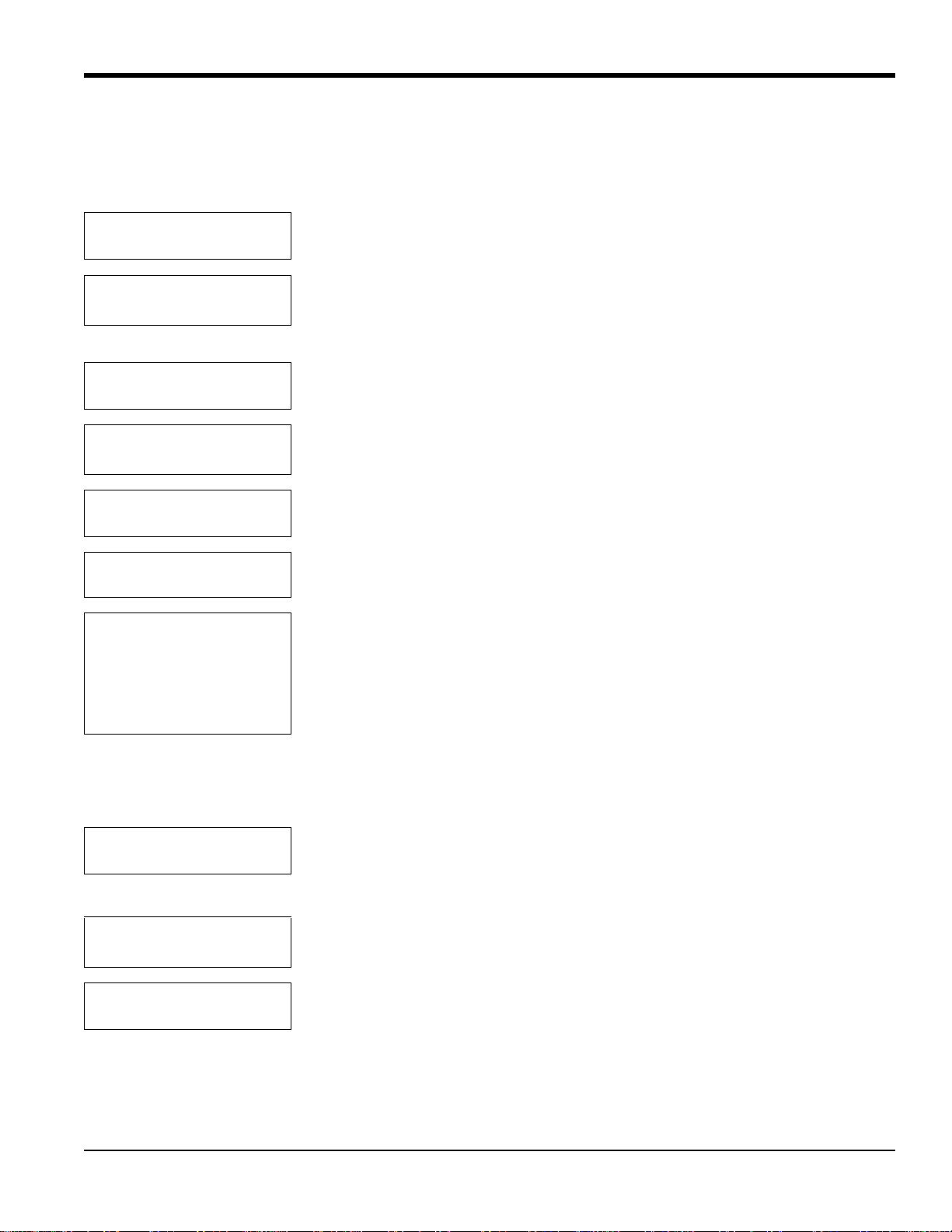
SETUP MENU
Set Error Handling?
Enable Error Handling
[YES] no
System Error Effects
Set Display Response?
Display System Error?
[YES] no
System Error Effects
Set Display Response?
SYSTEM ERROR EFFECTS
Set Output Response?
Select Output Effect:
No effect?
Force high?
Force low?
Force to value?
Hold last value?
Press [YES] to enter the Error Handling submenu.
Use the [NO] or arrow keys to select [YES] to enable Error Handling. Press [YES]
to confirm the selection. (Selecting [NO] returns the display to the Setup Menu.)
Press [YES] to enter the Display Response submenu.
Use the [NO] or arrow keys to select if the display will show errors. Press [YES] to
confirm the selection.
Press [NO] to proceed to the next submenu.
Press [YES] to enter the Output Response submenu.
Use [NO] or the arrow keys to scroll through the choices for output responses. When
you have reached the desired response, press [YES] to confirm the selection.
If you select any choice except Force to Value?, the program returns to the Set Output Response? entry. The Force to
Value? selection enables you to choose a value to which the output will go when a system error occurs. The mA value
must be set between 0 and 25 mA. If you select Force to Value?, the program asks for two more entries.
Output A, Error V alue:
mA Value [X.XX]:
Use the numeric keys to enter the desired value. (The number in brackets represents
the previously entered value.) Press [YES] to enter the value, and [YES] again to
confirm the entry.
Output B, Error V alue:
mA Value [X.XX]:
System Error Effects
Set Output Response?
TMO2D Digital Display User’s Manual 29
Use the numeric keys to enter the desired value. Press [YES] to enter the value, and
[YES] again to confirm the entry.
Press [NO] to proceed to the final submenu.
Page 38
Chapter 4. Basic Programming
4.4.8 Set Error Handling? (cont.)
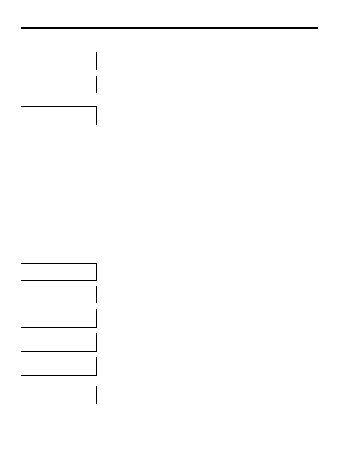
System Error Effects
Done?
SETUP MENU
Set Error Handling?
SETUP MENU
Done?
Press [YES] to return to the Setup Menu, or [NO] to continue scrolling through the
System Error Effects submenu.
Press [NO] to exit the Error Handling menu.
Press [YES] to exit the Setup Menu and return to the Main Menu. Press [NO] to
return to the “Set Time?” prompt.
You have completed the Setup Menu. At the Main Menu prompt, press [NO] to leave the Setup Menu and progress to
the Outputs Menu.
4.5 The Outputs Menu
The second main menu, the Outputs Menu, enables users to select which 4-20 mA output (A or B) to adjust, and to
enter all necessary information for either or both outputs.
The TMO2D provides a choice of one isolated 0/4-20 mA output, or two isolated 0/4-20 mA ou tputs. You can set both
options for a 0 to 20-mA or a 4-20 mA response, and scale the output anywhere within the range of the transmitter.
Note: The displ ay is programmed to accept settings for two outputs; however, if only a single isolated output is used,
only output A is effective.
The steps in the following example illustrate how to set up outputs. In this instance, output A will have a 0 to 20-mA
range, with 0 mA equal to 0% oxygen and 20 mA equal to 100% oxygen. (Appendix B offers a flow diagram of the
Outputs Menu in Figure 26 on page 79.)
MAIN MENU
Setup?
MAIN MENU
Outputs?
Select Output to set:
[A] B done
A Output Range (mA):
[0-20] 4-20
Output A 0 mA Value
[X.XX]:
%O
2
Output A 0 mA Value
[0.00]:
%O
2
Press [NO] to proceed to the Output Menu.
Press [YES] to enter the Output Menu.
Use the [NO] or arrow keys to move the brackets to “A,” and press [YES] to confirm
the selection.
Use the [NO] or arrow keys to select the desired output range, and press [YES] to
confirm the choice.
Use the numeric keys to enter the low end value. (The X’s represent the previously
entered value for 0 mA.)
Then press [YES] to confirm the entry and [YES] again to proceed to the high end
value.
30 TMO2D Digital Display User’s Manual
Page 39
4.5 The Outputs Menu (cont.)
Chapter 4. Basic Programming
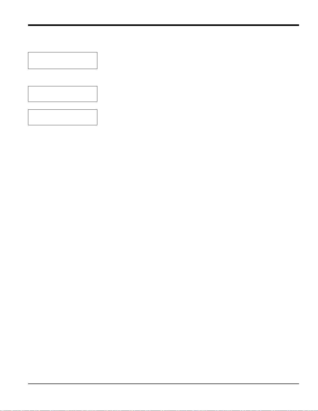
Output A 20 mA Value
[100%]:
%0
2
Repeat this procedure to program Output B, if desired. After entering the necessary values:
Select Output to set:
A B [DONE]
MAIN MENU
Outputs?
Use the numeric keys to enter the high end value. Press [YES] to enter the value, and
[YES] again to confirm the entry.
Use the [NO] or arrow keys to select “DONE.” Press [YES] to exit.
Press [NO] to proceed to the next Main Menu title — Relays.
4.6 The Relays Menu
The third main menu is the Relays Menu. The TMO2D includes two or four single-pole double throw (SPDT) relays
for use in activating alarm devices or driving automatic calibration solenoid valves. The display addresses the relays as
A, B, C or D. You can configure each relay as either an alarm or as an automatic calibration relay.
If the relay is configured as an alarm, it can be programmed to trip on up to five functions, listed below, and in either
Failsafe or Non-Failsafe mode:
• Low Gas Reading
• High Gas Reading
• System Fault Indicator
• Auto Calibration Error Indicator
• New Auto Calibration Data
If the relay is configured as an Auto-Calibration relay, the TMO2D offers two options:
• Process/Cal Relay
• Zero/Span Relay
If the transmitter requires a one gas offset or one gas span calibration, you need to set only one relay for
Auto-Calibration, with the Process/Cal option. However, if it requires a two-gas zero and span calibration, you must set
two relays for Auto-Calibration, one to Process/Cal and the other to Zero/Span.
TMO2D Digital Display User’s Manual 31
Page 40
Chapter 4. Basic Programming
4.6 The Relays Menu (cont.)
Refer to Figure 27 on page 80 for a flow diagram of the Relays Menu.
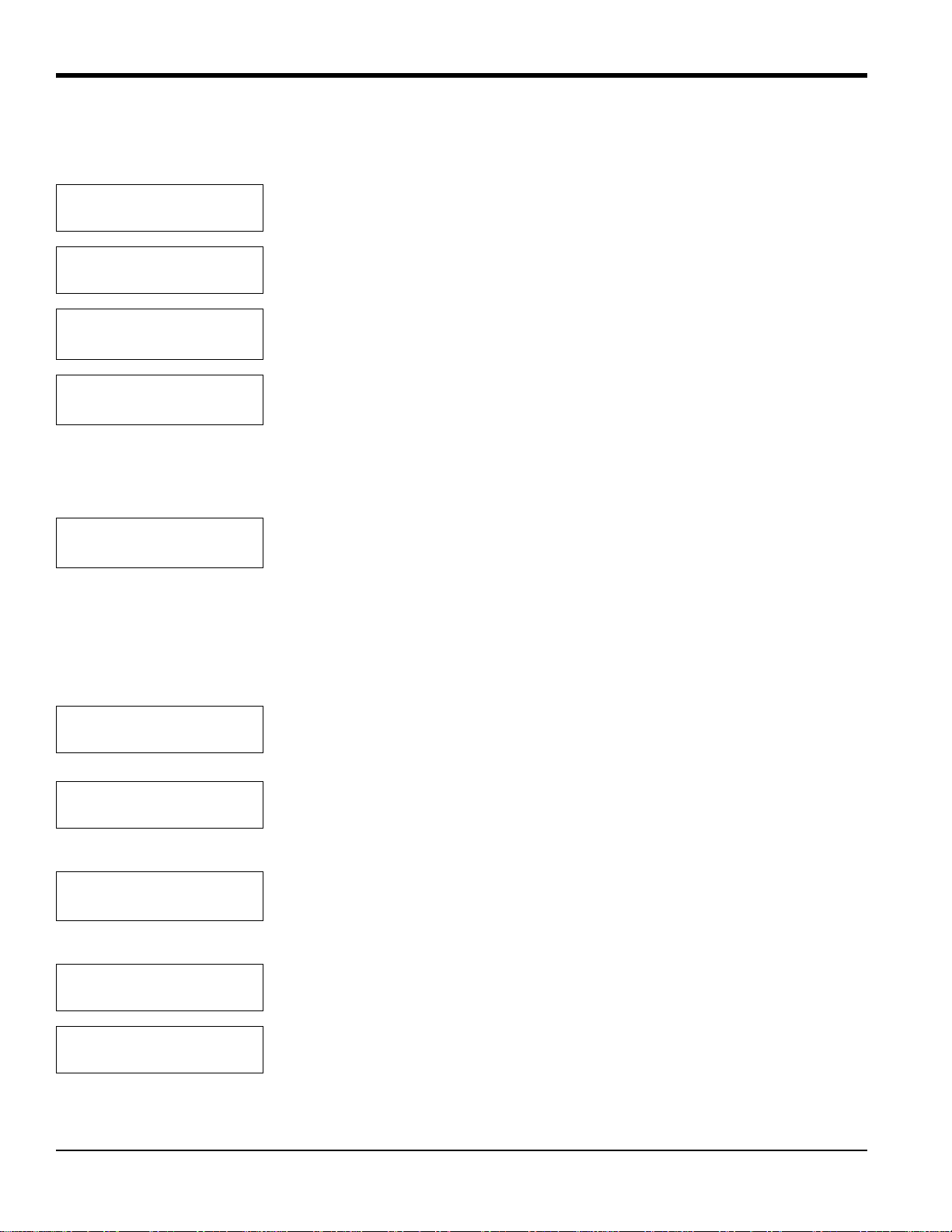
MAIN MENU
Setup?
MAIN MENU
Relays?
Select Relay to set:
[A] B C D done
Relay type:
[ALARM] autocalibration
Press [NO] to scroll through the Main Menu until the Relays Menu appears.
Press [YES] to enter the Relays Menu.
Use the [NO] or arrow keys to select the relay, and press [YES] to confirm the
selection.
Use the [NO] or arrow keys to select the relay type and press [YES] to confirm the
selection.
4.6.1 Autocalibration Type
If you select Autocalibration, the TMO2D asks for the Auto-Calibration option:
Auto-Cal Relay Type:
[PROC/CAL] zero/span
Use the [NO] or arrow keys to select the autocalibration type, and press [YES] to
confirm the selection.
For either selection, the program returns to the Select Relay to Set? entry. Refer to Auto Cal Parameters on page 42 to
define autocal parameters.
4.6.2 Alarm Type
If you select Alarm, the program displays a series of entries.
ALARM FEAT URES
Set Low Alarm Function?
Trip on Low%?
[NO] yes
Press [YES] to set the low alarm function.
Use the [NO] or arrow keys to indicate whether or not you wish the alarm to trip on
the low percentage, and press [YES] to confirm the selection. (Selecting [NO]
returns the program to the Set Low Alarm Function? entry.)
Alarm X, LOW Setpoint
[XX.X]
%O
2
Use the numeric keys to enter the desired value. Then press [YES] to enter the data,
and [YES] again to confirm the entry. (The X’s represent the previously entered
setpoint.)
ALARM FEAT URES
Set Low Alarm Function?
ALARM FEAT URES
Set High Alarm Function?
Press [NO] to proceed to the high alarm function.
Press [YES] to set the high alarm function.
32 TMO2D Digital Display User’s Manual
Page 41
4.6.2 Alarm Type (cont.)
Chapter 4. Basic Programming
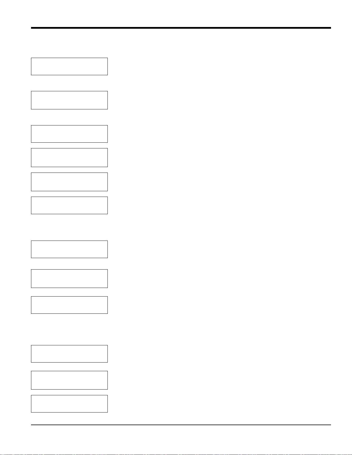
Trip on High%?
[NO] yes
Use the [NO] or arrow keys to indicate whether or not you wish the alarm to trip on
the high percentage, and press [YES] to confirm the selection. (Selecting [NO]
returns the program to the Set High Alarm Function? entry.)
Alarm X, HIGH Setpoint
[XX.X]:
%O
2
Use the numeric keys to enter the desired value. Then press [YES] to enter the data,
and [YES] again to confirm the entry. (The X’s represent the previously entered
setpoint.)
ALARM FEAT URES
Set High Alarm Function?
ALARM FEAT URES
Set System Fault Action?
Trip On System Faults?
[NO] yes
ALARM FEAT URES
Set System Fault Action?
Press [NO] to proceed to the system fault action entry.
Press [YES] to enter the system fault action function. Signal faults occur if the signal
from the transmitter drops below 1 mA or exceeds 24 mA.
Use the [NO] or arrow keys to indicate whether or not you wish the alarm to trip on
system faults, and press [YES] to confirm the selection.
Press [NO] to proceed to the cal error action entry.
The calibration error could occur if the TMO2D performs an autocal on a transmitter and the amount of drift exceeds a
programmed limit. You can set the limits in Change AutoCal Limits? on page 59.
ALARM FEAT URES
Set Cal Error Action?
Trip On Auto Cal Errors?
[NO] yes
ALARM FEAT URES
Set Cal Error Action?
Press [YES] to enter the cal error action function.
Use the [NO] or arrow keys to indicate whether or not you wish the alarm to trip on
autocalibration errors, and press [YES] to confirm the selection.
Press [NO] to proceed to the cal occurred action entry.
The Cal occurred alarm trips if autoverification is enabled and an automatic calibration is performed on a transmitter. If
the amount of drift exceeds the limits programmed, the TMO2D stores the new drift calibration data and trips an alarm
to indicate the change. For further details, refer to page 43 and Change AutoCal Limits? on page 59.
ALARM FEAT URES
Set Cal Occurred Action?
Trip On New Cal Data?
[NO] yes
ALARM FEAT URES
Set Cal Occurred Action?
Press [YES] to enter the cal occurred action function.
Use the [NO] or arrow keys to indicate whether or not you wish the alarm to trip on
new calibration data, and press [YES] to confirm the selection.
Press [NO] to proceed to the normal/failsafe mode function.
TMO2D Digital Display User’s Manual 33
Page 42
Chapter 4. Basic Programming
4.6.2 Alarm Type (cont.)
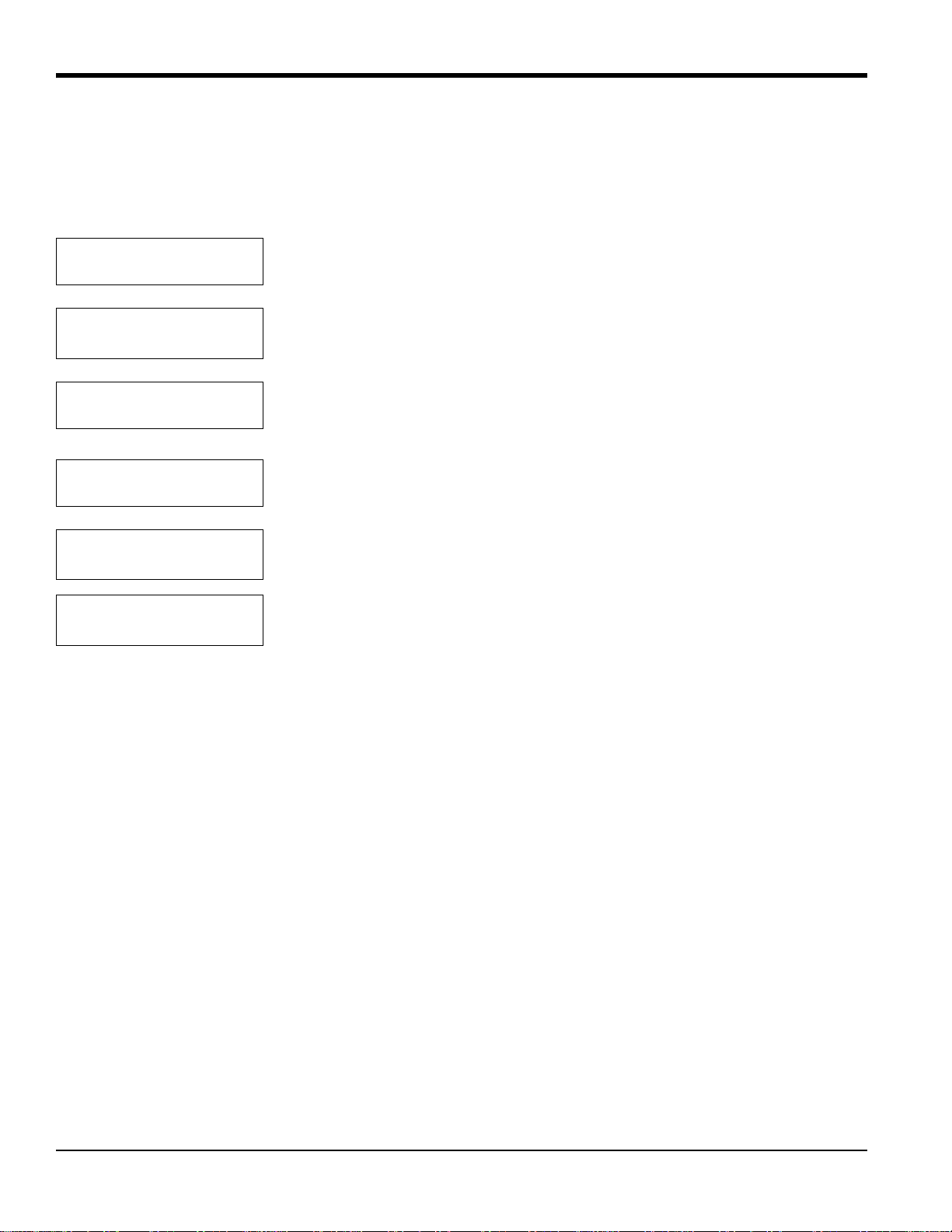
Users can configure the TMO2D alarms for either normal or failsafe mode. For normal alarm configuration, the alarm
contact remains de-energized until an alarm condition occurs. For failsafe mode, the alarm contact remains energized
until an alarm condition occurs, when it becomes de-energized.
ALARM FEAT URES
Normal/Failsafe Mode?
Failsafe Alarm?
[NORMAL] failsafe
ALARM FEAT URES
Normal/Failsafe Mode?
ALARM FEAT URES
Done?
Select Relay to set:
[A] B C D done
MAIN MENU
Relays?
4.7 The Tests Menu
Press [YES] to enter the normal/failsafe mode function.
Use the [NO] or arrow keys to indicate whether or not you wish the alarm to act as a
normal or failsafe alarm, and press [YES] to confirm the selection.
Press [NO] to exit the normal/failsafe mode function.
Press [YES] to leave the Alarms submenu.
Use the [NO] or arrow keys to select another relay, or select Done to leave the
Relays Menu. Press [YES] to confirm the selection.
Press [NO] to proceed to the next
menu — the Tests Menu.
The fourth main menu, the T ests Menu, provides assistance in testing and troubleshooting the inputs and outputs of the
TMO2D.
The Tests Menu contains three submenus:
• DVM Test
• Output Test
• Relays Test
(Refer to Figure 27 on page 80, for a flow diagram of the Tests Menu.)
34 TMO2D Digital Display User’s Manual
Page 43
Chapter 4. Basic Programming
4.7.1 DVM Test?
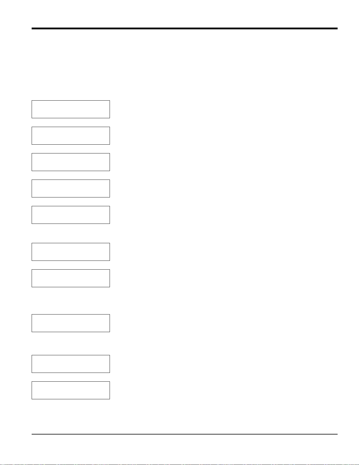
In the DVM Test mode, the display operates as a simple digital voltmeter to measure, in milliamps, the transmitter ’s
gas and, if appropriate, the compensation signals. The test updates the display approximately 20 times per second,
facilitating transmitter connection and calibration.
Follow the steps below to test the gas signal input from the transmitter.
MAIN MENU
Setup?
MAIN MENU
Tests?
TESTS
DVM Test?
Select DVM Input:
Gas Input?
GAS DVM TEST
X.XX mA
Select DVM Input:
Gas Input?
Select DVM Input:
Comp Input?
Press [NO] to scroll through the menu until the Tests Menu appears.
Press [YES] to enter the Test s Menu.
Press [YES] to select the DVM submenu.
Press [YES] to select the “GAS” input test.
The display will show the gas signal. (The X’s represent the milliamp signal, which
will update continuously during the test.) Press any key to return to the DVM
submenu.
Press [NO] to proceed to the compensation signal test.
Press [YES] to enter the compensation signal test.
The compensation signal input is only used on a TMO2 oxygen transmitter with external background gas or external
atmospheric pressure compensation.
COMP DVM TEST
X.XX mA
Press any key to return to the DVM submenu.
4.7.1a Done?
Select DVM Input:
Done?
TESTS
DVM Test?
TMO2D Digital Display User’s Manual 35
Press [NO] to scroll to “Done?” and press [YES] to exit the DVM test.
Press [NO] to proceed to the Output submenu.
Page 44
Chapter 4. Basic Programming
4.7.2 Output Test?
The Output Test? submenu enables the display to send a %Gas value to the output.
For example, to send a %Gas output of 36.39 to Output A:
TESTS
Output Test?
Select Output to test:
[A] B done
Set Output A to:
[XX.XX]:
%Gas
Set Output A to:
%Gas [36.39]:
Select Output to test:
A B [DONE]
TESTS
Output Test?
Press [NO] to scroll through the Tests Menu, and then press [YES] to select the
Output Test submenu.
Use the [NO] or arrow keys to select A, and press [YES] to confirm the selection.
Use the numeric keys to enter 3, 6, ., 3, and 9, and press [YES] to confirm the entry.
(The X’s represent the previously entered setpoint.)
Press [YES] to return to the calibration submenu.
Use the [NO] or arrow keys to select DONE, and press [YES] to exit the submenu.
Press [NO] to proceed to the next submenu — Relays Test.
4.7.3 Relays Test?
The Relays Test? menu enables you to trip and reset the relays using the keypad to test the operation of external
devices.
For example, to test relay A:
TESTS
Relays Test?
Select Relay to test:
[A] B C D done
Press [NO] to scroll through the Tests Menu, and then press [YES] to select the
Relays Test submenu.
Use the [NO] or arrow keys to select A, and press [YES] to confirm the selection.
Note: If you selec t a calibration relay to test, the TMO2D displays the following warning:
Warning! Cal-Relay, Test?
[NO] yes
Use the [NO] or arrow keys to choose to continue (or not) with the test, and press
[YES] to confirm the selection.
The program rejoins the main Relays Test menu.
Turn Relay A:
[ON] off done
36 TMO2D Digital Display User’s Manual
Use the [NO] or arrow keys to select “ON.” Press [YES] to confirm the ON
selection.
Page 45
Chapter 4. Basic Programming
4.7.3 Relays Test? (cont.)
Note: Upon sel ecting the OFF option and pressing [YES], the relay will turn off, and the selection brackets will skip
to ON. Upon selecting the ON option, the relay turns on, and the selection brackets s kip to OFF.
Turn Relay A:
on [OFF] done
Select Relay to test:
[A] B C D done
TESTS
Relays Test?
TESTS
Done?
MAIN MENU
Tests?
Use the [NO] or arrow keys to select “DONE.” Press [YES] to confirm the selection.
Use the [NO] or arrow keys to select “DONE” again, and press [YES] to confirm the
selection and exit.
Press [NO] to exit the Relays Test.
Press [YES] to exit the submenu.
Press [NO] to proceed to the next Main Menu title — the Calibration Menu.
4.8 The Calibration Menu
The fifth main menu, the Calibration Menu, enables you to enter measurement parameters and calibration data into the
TMO2D.
The Calibration Menu includes five submenus:
• Select Response?
• Select Compensation?
• Gas Calibration?
• Pressure Calibration?
• Auto Cal Parameters?
(Refer to Figure 28 on page 81 and Figure 29 on page 82 for a flow diagram of the Calibration Menu.)
TMO2D Digital Display User’s Manual 37
Page 46
Chapter 4. Basic Programming
4.8.1 Select Response?
In the Select Response? submenu, you can choose between a Fast and a Damped response for measuring gases. The
Fast response uses software to extrapolate a reading from existing data before the transmitter has completed the
measurement. The Damped response displays the actual readings from the transmitter without any software
enhancements. The factory default response is Damped.
Note: DO NOT use fast response in conjunction with pressure or background compensation. Also, do not use fast
response without tuning the response in the Advanced Menu (see page 57).
MAIN MENU
Calibration?
CALIBRA TION MENU
Select Response?
Set System Response:
[FAST] damped
CALIBRA TION MENU
Select Response?
Press [YES] to enter the Calibration Menu.
Press [YES] to enter the Select Response submenu.
Use the [NO] or arrow keys to scroll between the Fast and Damped choices, and
press [YES] to confirm the selection.
Press [NO] to proceed to the next submenu.
4.8.2 Select Compensation?
The Select Compensation? submenu enables you to select submenus to compensate for pressure or background gases; a
“None” selection is also available for applications that require no compensation.
Note: The TMO2 oxygen transmitter is the only device where compensation may be set to a value other than None.
CALIBRA TION MENU
Select Compensation?
Press [YES] to enter the “Select Compensation?” submenu.
Select Compensation:
[NONE] pres bkgd
CALIBRA TION MENU
Select Compensation?
38 TMO2D Digital Display User’s Manual
Use the [NO] or arrow keys to select the type of compensation desired. Then press
[YES] to confirm the selection.
Press [NO] to proceed to the “Gas Calibration?” submenu and enter data.
Page 47
Chapter 4. Basic Programming
4.8.3 Gas Calibration?
The Gas Calibration? submenu enables you to enter data from the transmitter calibration sheet. Depending on the
selection made in the Select Compensation? submenu, the display will present appropriate prompts for none, pressure,
or background compensation.
Refer to the following sections, depending on the type of compensation you have selected:
• None — see below.
• Pressure — refer to page 40.
• Background — refer to page 40.
CALIBRA TION MENU
Gas Calibration?
Press [YES] to enter the “Gas Calibration?” submenu. The menu will vary according
to the selection made in the “Select Compensation?” submenu.
4.8.3a No Compensation:
If you have selected NONE for compensation:
GAS GRID ENTRY
# of Points [X]:
Point # 1
Gas [XX.XX]:
Note: Percent gas concentrations MUST be in ascending order, with Point #1 the lowest concentration.
XX.XX %Gas
Gas mA [XX.XX]:
The menu will then display the “Working . . .” message before returning to the Gas Calibration? submenu.
CALIBRA TION MENU
Gas Calibration?
Use the numeric keys to enter the number of points in the gas calibration curve, then
press [YES] twice to confirm the entry.
Use the numeric keys to enter the percent gas concentrations for each of the points in
the curve, and then press [YES] to confirm each entry.
After entering all the points, use numeric keys to enter the corresponding mA values
for the given percent gas concentration. Press [YES] twice to confirm each entry.
Press [NO] to proceed to Pressure Calibration.
TMO2D Digital Display User’s Manual 39
Page 48
Chapter 4. Basic Programming
4.8.3b Pressure Compensation:
In the TMO2D, pressure (PRES) compensation is typically used only with a TMO2 oxygen transmitter. Pressure
compensation will correct the oxygen readings for any changes in atmospheric pressure. If you have selected pressure
compensation, you must enter both transducer data and pressure grid data.
PRESSURE GRID ENTRY
# of Curves?[X]:
Curve # 1
mmHg [XXX.X]:
PRESSURE GRID ENTRY
# of Points?[X]:
Point # 1
[XX.XX]
%O
2
Use the numeric keys to enter the number of pressure curves, then press [YES] twice
to confirm the entry.
Use the numeric keys to enter the pressure in mmHg for the first curve, and press
[YES] twice. Repeat this process for the other curves.
Use the numeric keys to enter the number of oxygen points per pressure curve, then
press [YES] twice to confirm the entry.
Use the numeric keys to enter the percent of oxygen for the given point, then press
[YES] twice to confirm the entry. Repeat this process for the other points.
The display will briefly show “Working . . .” before proceeding to the next question.
X.XX% O2 , XXX.X mmHg
Enter Point? [[YES]] no
The display will show the data entered for Curve #1, and ask if you wish to enter a
point. Use the [NO] or arrow keys to scroll between choices, and press [YES] to
confirm either a [YES] or [NO] selection. (If you select [NO], the menu proceeds to
the next point entered.)
.
X.XX% %O2, XXX.X mmHg
mA [X.XX]:
O
2
Use the numeric keys to enter the corresponding mA value for the given point, then
press [YES] twice to confirm the entry. Repeat this process for the other points.
The display again shows “Working . . .” before returning to the start of the Gas Calibration? submenu.
4.8.3c Background Compensation:
Background gas compensation in the TMO2D is typically used with a TMO2 oxygen transmitter to correct the readings
for changes in background gas concentrations. If you have selected background compensation (BKGD), you must enter
background grid data.
O2 GRID ENTRY
# of Curves [X]:
O2 GRID ENTRY
# of Points [X]:
Note: Each curve must have AT LEAST TWO entered data points.
Point #1:
[X.XX]:
%O
2
40 TMO2D Digital Display User’s Manual
Use the numeric keys to enter the number of background gas curves, then press
[YES] twice to confirm the entry.
Use the numeric keys to enter the number of oxygen points per curve, and press
[YES] twice to confirm the entry.
Use the numeric keys to enter the percent gas concentrations for each point, then
press [YES] twice to confirm the entry.
Page 49
Chapter 4. Basic Programming
4.8.3 Gas Calibration? (cont.)
Note: Percent gas concentrations MUST be in ascending order, with Point #1 the lowest concentration.
The display shows “Working . . .”
X.XX% O2 , Curve #1
Enter Point? [YES] no
The display will show the data entered for Curve #1, and ask if you wish to enter a
point. Use the [NO] or arrow keys to scroll between choices, and press [YES] to
confirm either a [YES] or NO selection. (If you select [NO], the menu proceeds to
the next point entered.)
X.XX % O
O2 mA [X.XX]
X.XX % O2, Curve #X
Bkgd mA [X.XX]:
Curve #X
2,
Use the numeric keys to enter the corresponding O2 input milliamp value for the
given point, then press [YES] twice to confirm the entry.
Use the numeric keys to enter the corresponding background gas compensation
input milliamp value for the given point. Press [YES] twice to confirm the entry , and
repeat the procedure for every point in the background grid.
The display will then show “Working . . .” before returning to the Gas Calibration submenu.
CALIBRA TION MENU
Gas Calibration?
Press [NO] to proceed to the Pressure Calibration submenu.
4.8.4 Pressure Calibration?
The Pressure Calibration? submenu enables users to directly calibrate the pressure transducer. While this menu option
is always displayed, it should only be programmed and used when the TMO2D is used with a TMO2 calibrated for
atmospheric pressure compensation.
CALIBRA TION MENU
Pressure Calib?
PRES XDUCER CURVE ENTRY
# of Points [X]:
Point # 1
mmHg [XXX.X]:
Point # 1
Pres mA [X.XX]:
Press [YES] to enter the “Pressure Calibration?” submenu.
Use the numeric keys to enter the number of points, and press [YES] twice to
confirm the entry.
Use the numeric keys to enter the pressure in mmHg for the given point, and press
[YES] twice to confirm the entry.
Use the numeric keys to enter the corresponding mA value for the point, and press
[YES] twice.
Repeat this sequence for the remaining points. After you have entered the data, the display will show “Working . . .”
and return to the start of the submenu.
CALIBRA TION MENU
Pressure Calib?
TMO2D Digital Display User’s Manual 41
Press [NO] to proceed to the Auto Cal submenu.
Page 50

Chapter 4. Basic Programming
4.8.5 Auto Cal Parameters
You can program the TMO2D to perform an automatic calibration procedure (Auto Cal) at specified time intervals
ranging from minutes to months.
By performing measurements on either one calibration gas (offset or span) or on two calibration gases (zero and span),
the unit can correct for changes in the response of the transmitter without operator intervention.
At the specified time interval, the TMO2D activates a solenoid valve on a sampling system using one of the relays
provided. This procedure isolates the transmitter from the process stream and connects the transmitter to one of the
calibration gases. After a programmable time, during which the calibration gas replaces the process gas, the transmitter
takes measurements of the calibration gas.
The analyzer then activates a second solenoid valve, using a second relay, to connect the transmitter to the other
calibration gas. The transmitter then equilibrates as the second calibration gas replaces the first gas, and takes
measurements of the second calibration gas.
After taking span and zero gas measurements, the TMO2D reconnects the transmitter to the process stream. Then a
final settling time takes place while the process gas replaces the calibration gas.
Once settling has been completed, if no error has occurred, the analyzer calculates the amount of drift and applies the
calculated drift to the factory calibration data. The factory calibration data remains unchanged. The TMO2D stores the
corrections to the calibration data as the Drift Curve.
If the Auto Cal measurements are beyond the preprogrammed limit, the unit disregards the data and uses the drift curve
already stored in memory. If you have enabled Auto Cal Error Handling (see page 47), the display and outputs will
respond as programmed. If any alarm relays have been assigned to trip on Auto Calibration Errors, they will be tripped.
Contact the factory to expand the AutoCal drift limits. The default limits are 25% of full scale per calibration and 40%
of full scale total drift.
Alternately , the automatic calibration can be performed in an of fset or span correction manner using a single calibration
gas and one solenoid valve. When calibration is active, the autocalibration status replaces the display of pressure or
background:
• Cal:ok (no errors and no new cal data applied)
• Cal:new (no errors and new data applied)
• Cal:err (total or per reading drift error)
Follow the steps below to enter the Auto Cal Parameters submenu.
CALIBRA TION MENU
Auto Cal Parameters?
Press [YES] to enter the Auto Cal Parameters submenu.
Enable AutoCal:
[YES] no
42 TMO2D Digital Display User’s Manual
Press [YES] to enable the AutoCal function.
Page 51
4.8.5 Auto Cal Parameters (cont.)
Chapter 4. Basic Programming
AUTO CALIBRATION MENU
Set Auto Verification?
AUTO CALIBRATION MENU
Set Time Interval?
AUTO CALIBRATION MENU
Set AutoCal Mode?
AUTO CALIBRATION MENU
Set Cal Gas Data?
AUTO CALIBRATION MENU
Set Settling Time?
AUTO CALIBRATION MENU
Set Error Handling?
AUTO CALIBRATION MENU
Perform AutoCal?
.
AUTO CALIBRATION MENU
Reset Drift?
Then use the [NO] or arrow keys to scroll through the ten options within the
submenu.
AUTO CALIBRATION MENU
View Drift Curve?
CALIBRATION MENU
Done?
Press [YES] to exit the Calibration Menu and return to the Main Menu.
4.8.5a Set Auto Verification?
Auto verification is similar to automatic calibration. The solenoids are still tripped to allow the calibration gases to
flow to the transmitter. However, if the calculated drift is less than a preprogrammed amount, the TMO2D will not
store the new drift data into memory. If the drift is beyond the verification limit and no cal error occurs, then the
TMO2D applies new calibration data and sets a new calibration flag.
Auto Cal Verification
disabled [ENABLED]
AUTO CALIBRATION MENU
Set Auto Verification?
TMO2D Digital Display User’s Manual 43
Use the [NO] or arrow keys to select enabling or disabling of auto cal verification.
Press [YES] to confirm your entry.
Press [NO] to proceed to the Time Interval option.
Page 52
Chapter 4. Basic Programming
4.8.5b Set Time Interval?
The Set Time Interval? option enables you to set the time interval at which an Auto Cal or Verification will occur.
Set Time Interval? enables you to set an interval of either hours or days. You can enter hours as fractions
(i.e., 90 minutes = 1.5 hours), up to a maximum of 24 hours.
Days can range from 0 to 99; however, the display does not accept fractional days. An interval of zero days prevents
Auto Cal from occurring. (You can still perform a manual field calibration through the Perform AutoCal option.) If you
enter a number of days (other than zero), the display will prompt for the time of day when the Auto Cal should occur.
For example, to set the time interval for 12 hours:
AUTO CALIBRATION MENU
Set Time Interval?
Select AutoCal Interval:
[HOURS] days
Auto-Cal Interval:
Hours [XX.XX]:
AUTO CALIBRATION MENU
Set Time Interval?
Scroll through the submenu, and press [YES] to enter the time interval option.
Use the [NO] or arrow keys to select HOURS. Press [YES] to confirm the selection.
Use the numeric keys to enter the number of hours. Press [YES] twice to confirm the
entry. Press [NO] to proceed. (The X’s represent the previously entered hours.)
The display returns to the Time Interval option.
To set the time interval for a given number of days:
AUTO CALIBRATION MENU
Set Time Interval?
Select AutoCal Interval:
hours [DAYS]
Auto-Cal Interval:
Days [XX.XX]:
Press [YES] to enter the Time Interval option.
Use the [NO] or arrow keys to select “DAYS” and press [YES].
Use the numeric keys to enter the number of days, and press [YES] twice to confirm
the entry. Press [NO] to proceed. (The X’s represent the previously entered days.)
To enter a time of day at which the display performs Auto Cal:
AutoCal at Time:
HH.MM [XX.XX]:
Auto-Cal Interval:
Days to Next Cal:[XX.XX]
Use numeric keys to enter the time (in 24-hour format). Press [YES] twice to
confirm the entry. Press [NO] to proceed. (X’s represent previously entered hours.)
Use the numeric keys to enter the number of days until the next auto cal , and press
[YES] twice to confirm the entry. Press [NO] to proceed. (The X’s represent the
previously entered days.)
Note: The number of days entered at this prompt can be no higher than the number of days entered at the “Days”
prompt above.
AUTO CALIBRATION MENU
Set Time Interval?
44 TMO2D Digital Display User’s Manual
Press [NO] to proceed to the “Set AutoCal Mode?” option.
Page 53
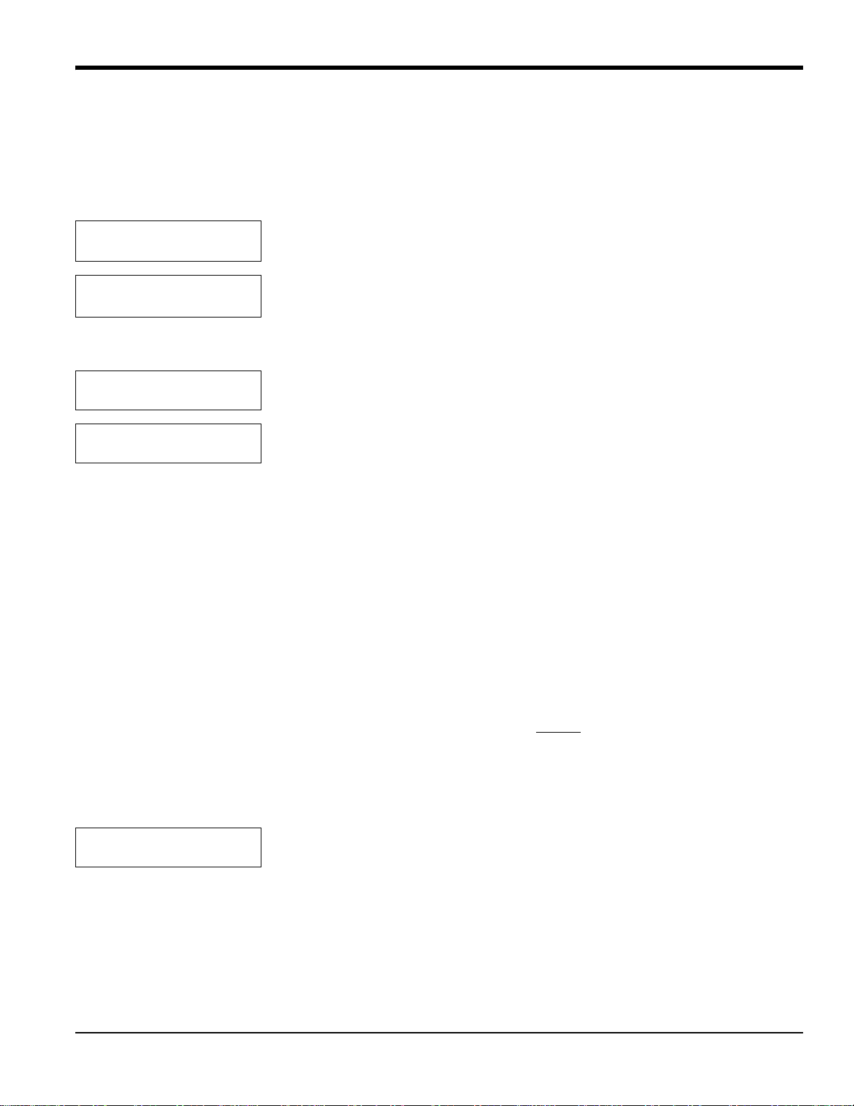
Chapter 4. Basic Programming
4.8.5c Set AutoCal Mode?
Most transmitters will have the best accuracy with a two-point zero and span calibration. Transmitters such as the
O2X1 oxygen transmitter have a fixed zero point, so only a one-gas span (slope) calibration is required. Set AutoCal
Mode? enables you to determine whether the display calibrates for both zero and span gases (two points) or simply for
one gas, either on offset or span (slope). To enter this option:
:
AUTO CALIBRATION MENU
Set AutoCal Mode
?
Scroll through the submenu, and press [YES] to enter the AutoCal Mode option.
Set AutoCal Type:
[1 GAS CAL] 2 gas cal
Use the [NO] or arrow keys to scroll to the desired selection, then press [YES].
If you select 1 gas cal, the following prompt appears:
Set 1Gas Auto Cal Type
[OFFSET-CAL] span-cal
AUTO CALIBRATION MENU
Set AutoCal Mode
Use the [NO] or arrow keys to scroll to the desired selection, then press [YES].
Press [NO] to proceed to the “Set Cal Gas Data?” option.
4.8.5d Set Cal Gas Data?
In the “Set Cal Gas Data?” option, you can program the zero, span or offset gases. If you select the “2 gas cal” mode,
the prompts ask for zero and span gas data. But if you select the “1 gas cal” mode, the prompt asks for data for either
the offset or span gas, depending on the mode selected in the Set AutoCal Mode? on page 45.
For an oxygen transmitter, if 100% nitrogen is used for the zero gas, the concentration would be zero. If a mixture is
used, you should enter the oxygen concentration of the mixture. The default concentration is 0% oxygen.
After you enter the gas concentration, the display will automatically prompt for the equilibration time for the zero gas.
The equilibration time should allow for the distance the calibration gas must travel, and for the settling time of the
transmitter cell.
Note: For a successful auto calibration, the equilibration time should be at least
3 minutes.The default is 5 minutes.
For testing purposes, the equilibration time can be as low as 0 seconds. The maximum equilibration time is 90
minutes.
For example, to set the zero gas in a 2-gas cal mode for 0.00% oxygen for an equilibration time of 3 minutes:
AUTO CALIBRATION MENU
Set Zero Gas?
TMO2D Digital Display User’s Manual 45
Scroll through the submenu, and press [YES] to enter the Set Zero Gas option.
Page 54
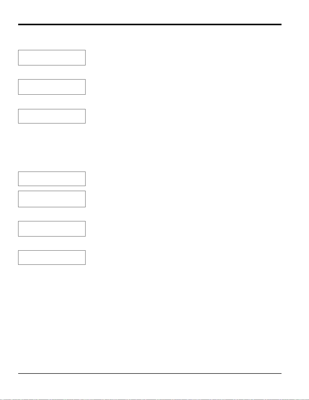
Chapter 4. Basic Programming
4.8.5d Set Gas Cal Data? (cont.)
Zero Gas
% O2 [XX.XX]
Use the numeric keys to enter the percentage of oxygen (in this case, 0, ., 0 and 0).
Press [YES] twice to confirm the entry. (The X’s represent the previously entered
percentage.)
Zero Gas ON for:
MM.SS [XX.XX]:
Use the numeric keys to enter the number of minutes and seconds needed for
equilibration time (in this case, 3, ., 0 and 0, or simply 3). Then press [YES] twice to
confirm the entry. (The X’s represent the previously entered minutes and seconds.)
AUTO CALIBRATION MENU
Set Zero Gas?
Press [NO] to proceed to the Set Span Gas option.
In the 2-gas cal mode, the Set Span Gas option enables you to enter the oxygen concentration and the equilibration time
for the span gas. The default concentration for the Span Gas is 20.93%, the concentration of oxygen in air. The
procedure to set the span gas is identical to that for setting the zero gas.
To set a span gas of 100% oxygen for 2 minutes and 35 seconds:
AUTO CALIBRATION MENU
Set Span Gas?
Span Gas
[XX.XX]
% O
2
Scroll through the submenu, and press [YES] to enter the Set Span Gas option.
Use the numeric keys to enter the percentage of oxygen (here 1,0,0, ., and 0,). Press
[YES] twice to confirm the entry. (The X’s represent the previously entered
percentage.)
Span Gas ON for
MM.SS [XX.XX]:
Use the numeric keys to enter the minutes and seconds for the equilibration time (in
this case 2, ., 3 and 5). Press [YES] twice to confirm the entry. (The X’s represent the
previously entered time.)
AUTO CALIBRATION MENU
Set Span Gas?
Press [NO] to proceed to the Set Settling Time option.
Note: In the 1-gas cal mode, ent ering offset gas data i s similar to entering the zero or span gas data described above.
46 TMO2D Digital Display User’s Manual
Page 55
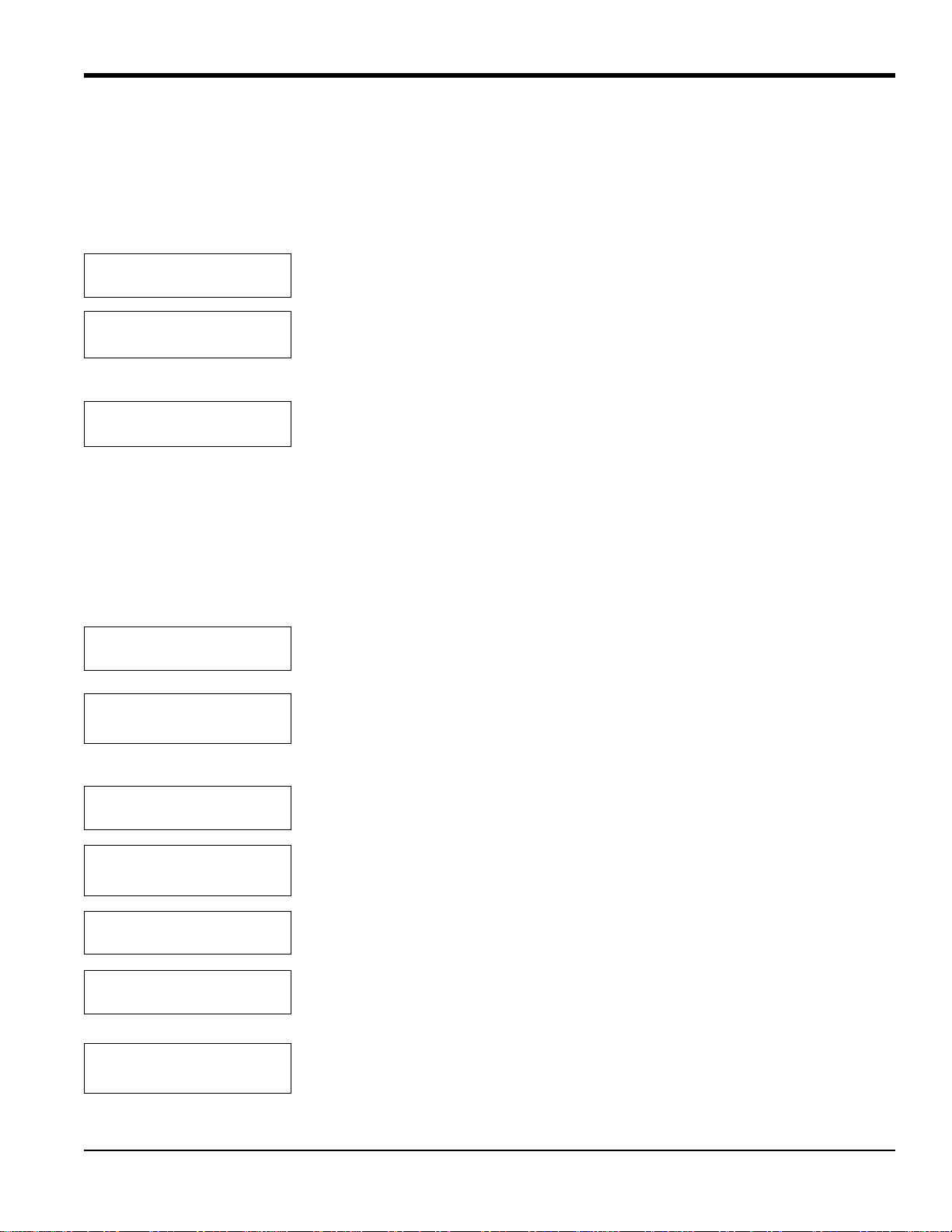
Chapter 4. Basic Programming
4.8.5e Set Settling Time?
In the Set Settling Time option, you can enter (in minutes and seconds) the settling time, the amount of time the process
gas should remain on before the TMO2D resumes taking measurements and reactivates the recorder output. (During an
autocal, the recorder output from the TMO2D has been locked to the last value it had sent directly before the autocal
began.)
AUTO CALIBRATION MENU
Set Settling Time?
Scroll through the submenu, and press [YES] to enter the Set Settling Time option.
.
Settling Time:
MM.SS [XX.XX]:
Use the numeric keys to enter the minutes and seconds for settling time, and press
[YES] twice to confirm the entry. Press [NO] to proceed.(The X’s represent the
previously entered time.)
AUTO CALIBRATION MENU
Set Settling Time?
Press [NO] to proceed to the “Set Error Handling?” option.
4.8.5f Set Error Handling?
Use the Set Error Handling? option to program the display and the recorder outputs to respond to any error (invalid
measurement) that occurs during Auto Cal. Errors occur if the measured drift values exceed preprogrammed limits (as
explained on page 42). To program alarm relays to respond to calibration errors, go to the Relays Menu (page 31).
Follow these steps to enable error handling, set the display screen, and select the output responses.
AUTO CALIBRATION MENU
Set Error Handling?
Enable Error Handling
[YES] no
Scroll through the submenu, and press [YES] to enter the Set Error Handling option.
Use the [NO] or arrow keys to scroll to [YES], and press [YES] to confirm the
selection.
AUTOCAL ERROR EFFECTS
Set Display Response?
Display AutoCal Error?
[YES] no
AUTOCAL ERROR EFFECTS
Set Display Response?
.
AUTOCAL ERROR EFFECTS
Set Output Response?
Set Output Response
No Effect?
TMO2D Digital Display User’s Manual 47
Press [YES] to set the Display Response.
Use the [NO] or arrow keys to make the desired selection, and then press [YES] to
confirm the entry.
Press [NO] to proceed to the next item.
Press [YES] to set the Output Response.
Use the [NO] or arrow keys to scroll through the choices, then press [YES] at the
desired output response.
Page 56
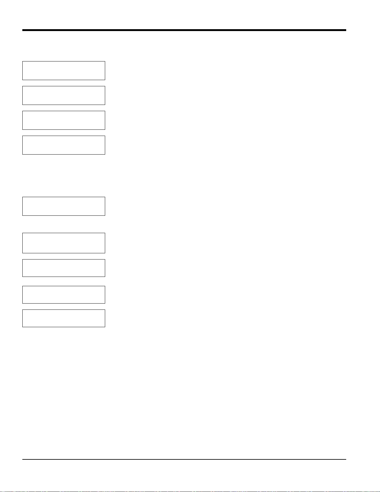
Chapter 4. Basic Programming
4.8.5f Set Error Handling? (cont.)
Set Output Response
Force High?
Set Output Response
Force Low?
Set Output Response
Force to Value?
Set Output Response
Hold Last V alue?
If you select any choice except Force to Value?, the program returns to the Set Output Response? entry. The Force to
Value? selection enables users to choose a value to which the output will go when a system error occurs from 0 to 25
mA. If you select Force to Value?, the program asks for two more entries.
Output A, Error V alue:
mA Value [X.XX]:
Output B, Error V alue:
mA Value [X.XX]:
AUTOCAL ERROR EFFECTS
Set Output Response?
AUTOCAL ERROR EFFECTS
Done?
AUTO CALIBRATION MENU
Set Error Handling?
Use the numeric keys to enter the desired value. (The number in brackets represents
the previously entered value.) Press [YES] to enter the value, and [YES] again to
confirm the entry.
Use the numeric keys to enter the desired value. Press [YES] to enter the value, and
[YES] again to confirm the entry.
Press [NO] to proceed to the next item.
Press [YES] to exit the Error Effects submenu.
Press [NO] to proceed to the Perform Auto Cal? option.
48 TMO2D Digital Display User’s Manual
Page 57

Chapter 4. Basic Programming
4.8.5g Perform AutoCal?
The Perform AutoCal? option can activate the Auto Cal procedure without waiting for the specified Auto Cal interval.
To set Auto Cal to begin automatically, refer to page 42.
When the TMO2D performs an Auto Cal, either upon user command or at a prespecified time, it performs several
operations.
• The Process/Cal relay will trip to the Cal position, and the Zero/Span relay will trip to the Span position. Refer to
the Relays Menu (page 31) to configure relays for calibration control.
For a 1 gas cal configuration:
• The first line of the display reads either “AutoCal: Span Gas is ON” or “AutoCal: Offset Gas is ON” (depending on
the active mode) along with the equilibration time, which counts down to zero.
Y
ou can interrupt the Auto Cal at this point by pressing [NO]. The Display will prompt Abort AutoCal? You have two
choices.
• Press [NO] to resume the countdown.
• Press [YES] to return the display to the beginning of the Perform Auto Cal? option.
When the equilibration time reaches zero, the display will read Measuring . . . and count down the measurement time.
At the end of the Auto Cal procedure, the Process/Cal relay will reset to the Process position and the settling time will
count down to zero. The display will then read AutoCal in Progress and the TMO2D will return to the start of the
Perform Auto Cal? option.
For a 2-gas-cal configuration:
• The first line of the display reads “AutoCal: Span Gas is ON” along with the equilibration time, which counts down
to zero.
Y
ou can interrupt the Auto Cal at this point by pressing [NO]. The Display will prompt Abort AutoCal? You have two
choices.
• Press [NO] to resume the countdown.
• Press [YES] to return the display to the beginning of the Perform Auto Cal? option.
When the equilibration time reaches zero, the display will read “Measuring . . .” and count down the measurement
time. At the end of the measurement, the display changes to “AutoCal: Zero Gas is ON”, along with its equilibration
time, which also counts down to zero.
At the end of the Auto Cal procedure, the Process/Cal relay will reset to the Process position and the settling time will
count down to zero. The display will then read “AutoCal in Progress” and the TMO2D will return to the start of the
Perform Auto Cal? option.
TMO2D Digital Display User’s Manual 49
Page 58
Chapter 4. Basic Programming
4.8.5g Perform AutoCal? (cont.)
To manually activate the Auto Cal procedure:
AUTO CALIBRATION MENU
Perform Auto Cal?
AutoCal: Span Gas is ON
XX.XX mA XX:XX
AutoCal: Span Gas is ON
Measuring . . .
AutoCal: Zero Gas is ON
XX.XX mA XX:XX
AutoCal: Zero Gas is ON
Measuring . . .
Press [YES] to activate Auto Cal.
If you press [NO] while any of these screens are on, the display will show:
Abort AutoCal?
Pressing [NO] sends the display back to the previous screen, while pressing [YES]
sends the display ahead to “Settling . . .” and then back to the start of the option.
AutoCal:Settling . . .
XX.XX XX:XX
The display then counts down the settling time.
If you press [NO] while the Settling screen is on, the display will show:
Abort AutoCal?
Pressing [NO] sends the display back to the previous screen, while pressing [YES]
sends the display back to the start of the option.
AUTO CALIBRATION MENU
Perform AutoCal?
After counting down the settling time, the display returns to the start of the “Perform
Auto Cal?” option. Press [NO] to proceed to the “Reset Drift?” option.
50 TMO2D Digital Display User’s Manual
Page 59
Chapter 4. Basic Programming
4.8.5h Reset Drift?
Selecting the “Reset Drift?” option prompts the display to reset the Auto Cal drift curve to the original calibration data.
AUTO CALIBRATION MENU
Reset Drift?
Reset Drift?
[YES] no
Working . . .
AUTO CALIBRATION MENU
Reset Drift?
Press [YES] to enter the “Reset Drift?” option.
Use the [NO] or arrow keys to select the desired entry. Select and press [YES] to
reset the Auto Cal drift curve.
After resetting the curve (or if you press [NO] to cancel the process), the display
returns to the Auto Cal Menu. Press [NO] to proceed to the next option.
4.8.5i View Drift Curve?
Selecting this option enables the user to view the Auto Cal drift curve.
AUTO CALIBRATION MENU
View Drift Curve?
Drift Values:
X.XX % Gas, X.XX mA
Press [YES] to enter the View Drift Curve option.
Press [YES] to scroll through the values of the drift curve.
Note: If the unit is uncalibrated and/or has not undergone the Auto Cal procedure (no calibration data has been
previously entered), the drift values will all be 0.00 mA.
AUTO CALIBRATION MENU
View Drift Curve?
AUTO CALIBRATION MENU
Done?
CALIBRA TION MENU
Auto Cal Parameters?
After it goes through the points, the display returns to the View Drift Curve option.
Press [NO] to exit the option.
Press [YES] to return to the Calibration Menu.
Then press [NO] to exit the Auto Cal Parameters submenu.
4.8.5j Done?
CALIBRA TION MENU
Done?
MAIN MENU
Calibration?
Press [YES] to exit the Calibration Menu and return to the Main Menu.
Press [NO] to proceed to the System Log menu.
TMO2D Digital Display User’s Manual 51
Page 60

Chapter 4. Basic Programming
4.9 The System Log Menu
The TMO2D maintains a System Log in battery-backed memory. Among other things, this log indicates the nature of
any fault signaled by the fault alarm relay by recording the type, date, and time of the relevant events.
The System Log can record up to 25 events of the following types:
• factory initialization
• system power on
• system RESET
• RAM checksum failure (memory corruption)
• Transmitter cell under range
• Transmitter cell over range
• no calibration curve
• return to normal operation
• AutoCal Tot drift error
• AutoCal Drift/Cal error
Note: Testing the fault alarm does not appear in the System Log.
The TMO2D stores only the 25 most recent events in its memory. When additional events occur, the TMO2D discards
the oldest event from the log to make room for the new event. Refer to Figure 29 on page 82, for a flow diagram of the
System Log menu.
52 TMO2D Digital Display User’s Manual
Page 61
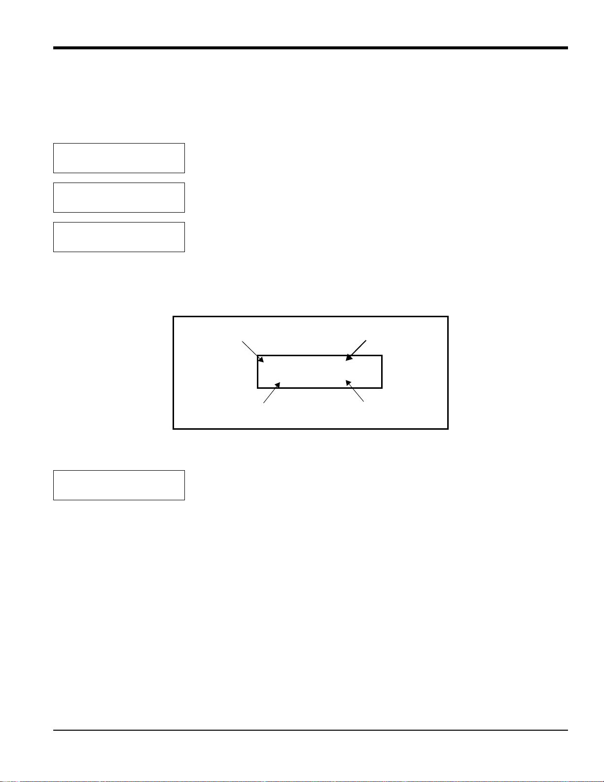
Chapter 4. Basic Programming
03: Normal Operation:
04/04/02 10:21:58
Event Number (0-24)
Type of Event
Date of Event
Time of Event
4.9.1 Viewing the System Log
The System Log may be viewed on the TMO2D display, or transmitted to a computer, printer or other data acquisition
system using the RS232 serial port. To view the System Log on the TMO2D display, scroll through the Main Menu
until you reach the following prompt:
MAIN MENU
System Log?
SYSTEM LOG MENU
Display System Log?
03: Normal Operation:
04/04/02 10:21:58
At the above prompt, use the arrow keys to scroll through the logged events ([]
Press [YES] to enter the System Log menu.
Press [YES] to view the most recent event in the System Log.
The TMO2D displays the most recent event in the System Log.
for the previous event, [] for the
next event). When done, press [NO] to exit the System Log. See Figure 14 below for a description of the components
of the System Log screen.
Figure 14: System Log Display Screen
SYSTEM LOG MENU
Display System Log?
TMO2D Digital Display User’s Manual 53
Press [NO] to proceed to the Print System Log? prompt.
Page 62
Chapter 4. Basic Programming
00: Factory Init at 10/02/2001 09:34:32
01: Cell Under Range at: 10/02/2001 09:34:33
02: No Calibration at: 10/05/2001 10:14:44
03: Normal Operation: 10/05/2001 10:21:58
4.9.2 Print System Log
To print the System Log or transmit it over the RS232 serial port:
SYSTEM LOG MENU
Print System Log?
Press [YES] and the TMO2D transmits the entire log using the RS232 serial port.
A System Log printout appears similar to the example shown in Figure 15 below.
Figure 15: A Typical System Log Printout
After printing or transmitting the log, the TMO2D reboots and returns to taking measurements.
4.9.2a Done?
To exit the System Log menu, proceed as follows:
SYSTEM LOG MENU
Print System Log?
Press [NO].
SYSTEM LOG MENU
Done?
MAIN MENU
System Log?
MAIN MENU
Resume?
Press [YES] to leave the System Log menu.
Press [NO].
Press [YES] for the TMO2D to resume taking measurements.
54 TMO2D Digital Display User’s Manual
Page 63

Chapter 5. Advanced Programming
Chapter 5. Advanced Programming
5.1 Introduction
In addition to its basic program, the TMO2D analyzer contains a factory setup program that enables the user to perform
more advanced operations on the parameters that have been first installed at the factory. This program has eight main
menus. Use the front panel keypad and display to check or change the settings for current operating parameters. New
data overrides any previously entered data.
IMPORTANT: Consult GE before changing any parameters in this menu.
The user program consists of eight main menus:
• Set Significant Digits
• Select Background
• Select Tracking
• Select Tertiary
• Response Parameters
• Labcal Outputs
• Manual Offset
• Change AutoCal Limits
5.2 Entering Data into the Factory Setup Program
To enter data into the program or to check previously entered values, enter the Factory Setup Menu Mode. When you
turn the power on, the TMO2D enters the Operate Mode. To enter the Factory Setup Menu Mode:
1. Press the [NO] key.
2. Key in the code [3] [6] [9]. The TMO2D will display an asterisk (*) after you enter each digit.
If you enter an incorrect code or press a non-numeric ([YES]/[NO] or arrow) key rather than 3 6 9, the LCD will
automatically resume displaying data, and you must press [NO] to re-attempt the code. Once all three digits have been
entered correctly, the display will cease collecting data and the LCD will switch to the Factory Setup Menu Mode.
The LCD screen now displays the Set Significant Digits? menu, the first of the eight main menus. At this display, press
[YES] to enter this menu, or [NO] to scroll to the next menu. Pressing [NO] continuously scrolls through all eight main
menus. Refer to Figure 30 on page 83 for a flow diagram of the Factory Setup Menu.
Note: The first eight options are main menus, while the “RESUME” prompt enables you to exit the Factory Setup
Menu Mode and return to Operate Mode.
TMO2D Digital Display User’s Manual 55
Page 64
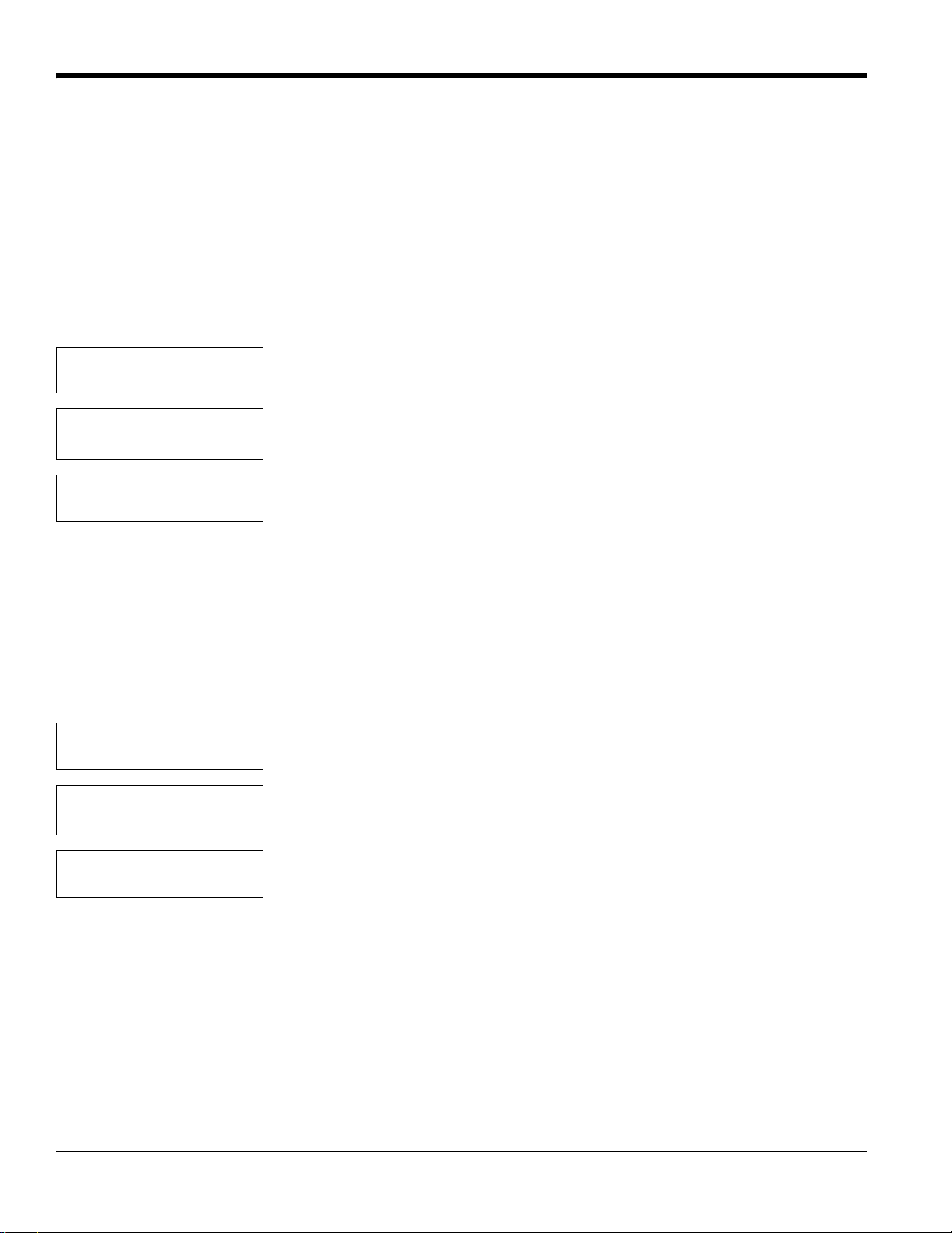
Chapter 5. Advanced Programming
5.3 Set Significant Digits?
The first option in the Factory Setup Menu, Set Significant Digits?, enables you to modify the resolution of the gas
reading on the TMO2D display, when you select display in PPM ranges. Y o u can select values from 2 to 4; the default
setting of 3 suppresses one significant digit, a setting of 2 suppresses two digits, and a setting of 4 displays the full
resolution of the calculated gas reading. However, while the Significant Digits option affects the display, the analog
outputs retain full resolution at all times.
Note: This option applies only if you select display in ppm ranges. If the TMO2D is set up for the 10 ppm range, it
defaults to 2-digit resolution. However, you can change the significant digits in this menu.
FACTORY SETUP MENU
Set Significant Digits?
Significant Digits:
2-4 [3]:
FACTORY SETUP MENU
Set Significant Digits?
Press [YES] to set the number of digits desired.
Use the numeric keys to enter the desired number of digits. Press [YES] to enter the
number, and [YES] again to confirm the entry.
Press [NO] to proceed to the Set Background option.
5.4 Select Background?
The Select Backgr ound ? option enables you to select a backgroun d gas label if backgrou nd compensation is active and
the LCD has been programmed to display the background gas.
Note: Background compensation and display apply only for a TMO2 oxygen transmitter. If the Auto Calibration
mode is active, the TMO2D displays calibration status instead of the background gas.
FACTORY SETUP MENU
Select Background?
Select Background Gas:
%Bkgd?
Press [YES] to select the background gas label.
Use the [NO] or arrow key to move brackets to the desired entry. The program of fers
five label choices: Bkgd, H2, N2, SO2, and CO2. Press [YES] to confirm the entry.
FACTORY SETUP MENU
Select Background?
56 TMO2D Digital Display User’s Manual
Press [NO] to proceed to the Select Tracking? option.
Page 65
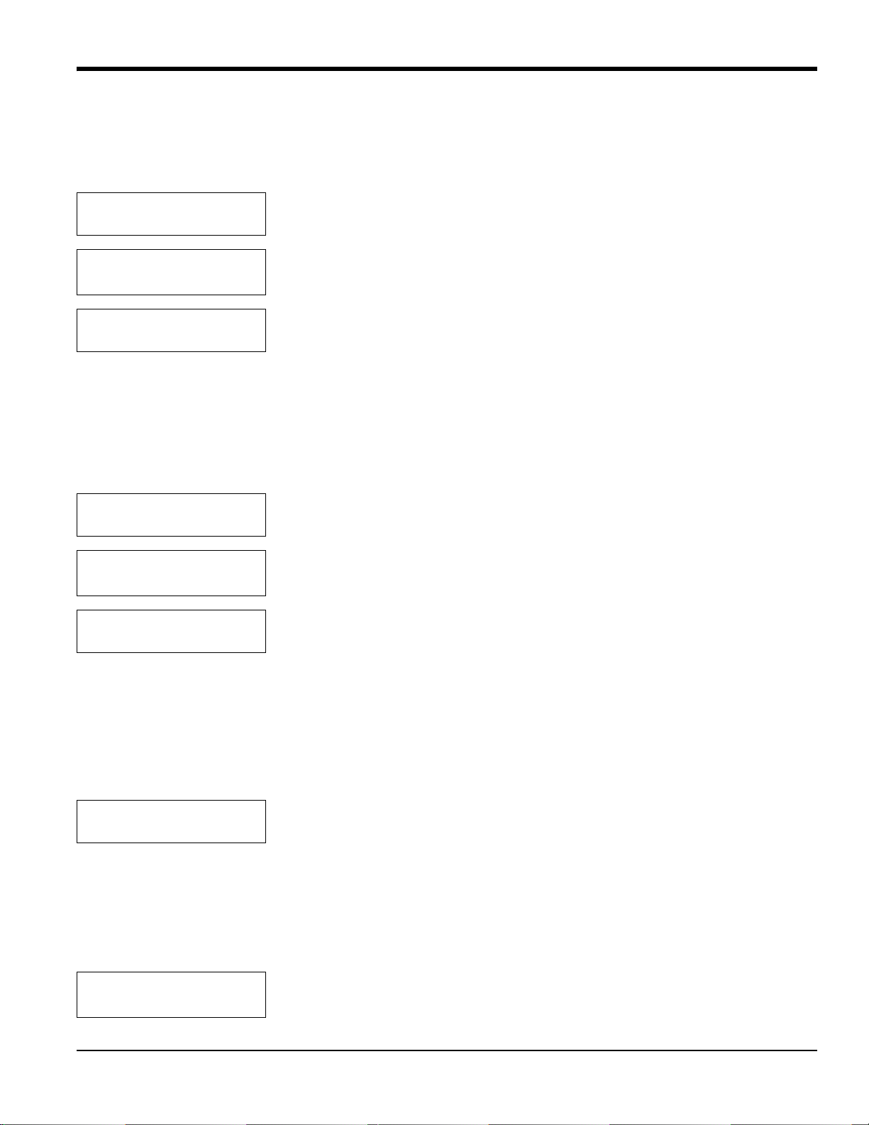
Chapter 5. Advanced Programming
5.5 Select Tracking?
If you use a background gas, the Select Tracking? option enables the TMO2D to use the last data point as the starting
point for the calculation.
FACTORY SETUP MENU
Select Tracking?
Turn Tracking:
[ON] off
FACTORY SETUP MENU
Select Tracking?
Press [YES] to select tracking.
Use the [NO] or arrow keys to scroll to the desired option. Press [YES] to confirm
the entry.
Press [NO] to proceed to the Select Tertiary? option.
5.6 Select Tertiary?
When activated, the Select Tertiary? option enables the TMO2D to calculate the ratio of background gases in the
process.
Note: This option applies only for a TMO2 oxygen transmitter.
FACTORY SETUP MENU
Select Tertiary?
Turn Tertiary:
[ON] off
Press [YES] to select tertiary calculation.
Use the [NO] or arrow keys to scroll to the desired option. Press [YES] to confirm
the entry.
FACTORY SETUP MENU
Select Tertiary?
Press [NO] to proceed to the Response Parameters? option.
5.7 Response Parameters?
If the system response on the TMO2D is set to FAST (see Select Response? on page 38), you can program the settings
for the Fast Response algorithm.
IMPORTANT: If you wish to use Fast Response, consult the factory.
FACTORY SETUP MENU
Response Parameters?
The first setting, Tau (up), is the tau value for calculations while the measured gas concentration is increasing.
Increasing the Tau (up) reading increases the transmitter’s response speed.
Note: Be careful when setting the Tau (up) or (down) values. Values that are too high may cause the TMO2D
readings to overshoot the actual end point.
FACTORY SETUP MENU
Tau (up) [XX.XX]:
Press [YES] to set the parameters for the Fast Response algorithm.
Use the numeric keys to enter the desired value. Press [YES] to enter the number,
and [YES] again to confirm the entry.
TMO2D Digital Display User’s Manual 57
Page 66
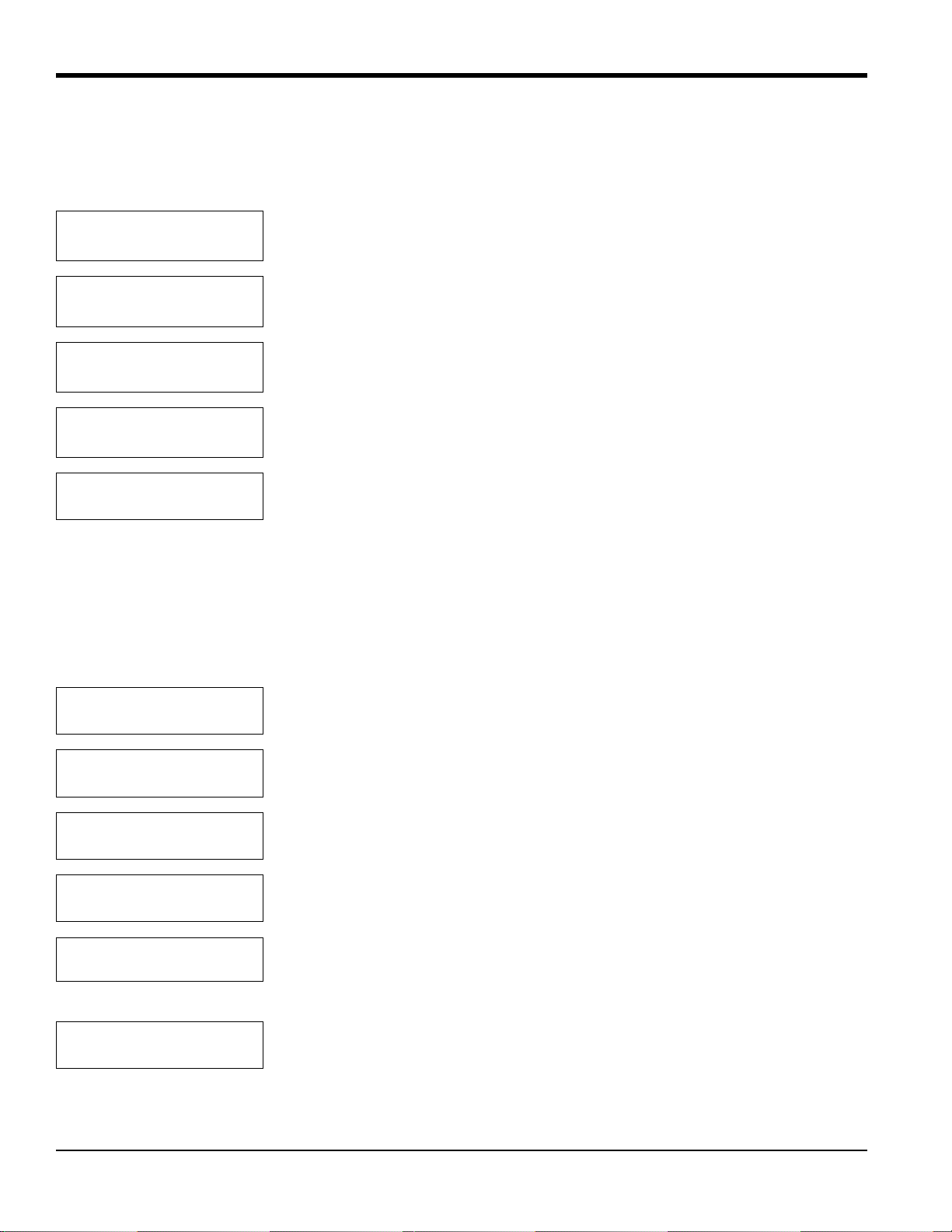
Chapter 5. Advanced Programming
5.7 Response Parameters? (cont.)
The next setting, Tau (down), is the tau value for calculations while the measured gas concentration is decreasing.
Increasing the Tau (down) reading increases the transmitter’s response speed.
FACTORY SETUP MENU
Tau (down) [XX.XX]:
FACTORY SETUP MENU
Thresh (%) [XX.XX]:
FACTORY SETUP MENU
Smooth (%) [XX.XX]:
FACTORY SETUP MENU
Window (%) [XX.XX]:
FACTORY SETUP MENU
Response Parameters?
Use the numeric keys to enter the desired value. Press [YES] to enter the number,
and [YES] again to confirm the entry.
Use the numeric keys to enter the desired value. Press [YES] to enter the number,
and [YES] again to confirm the entry.
Use the numeric keys to enter the desired value. Press [YES] to enter the number,
and [YES] again to confirm the entry.
Use the numeric keys to enter the desired value. Press [YES] to enter the number,
and [YES] again to confirm the entry.
Press [NO] to proceed to the LabCal Outputs? option.
5.8 LabCal Outputs?
The LabCal Outputs? option enables you to calibrate (or trim) the analog outputs. After you select the output (A or B)
to calibrate, the output is driven to 20 mA. You can input the actual output value (as shown by a multimeter or
connected control device) and adjust the output. The output is then driven to 4 mA, and you can make a similar
adjustment.
FACTORY SETUP MENU
LabCal Outputs?
Output to LabCal:
[A] B done
Output A 20 mA Output
Enter mA [20.00]:
Output A 4 mA Output
Enter mA [4.00]:
Output to LabCal:
A [B] done
FACTORY SETUP MENU
LabCal Outputs?
Press [YES] to calibrate the analog outputs.
Use the [NO] or arrow keys to scroll to the desired output. Press [YES] to confirm
the entry.
Use the numeric keys to enter actual output value (as read by a multimeter or control
device). Press [YES] to enter the number, and [YES] again to confirm the entry.
Use the numeric keys to enter actual output value (as read by a multimeter or control
device). Press [YES] to enter the number, and [YES] again to confirm the entry.
Use the [NO] or arrow keys to scroll to another output to repeat the calibration
procedure. Press [YES] to confirm the entry. If you have completed calibration,
scroll to “Done” and press [YES].
Press [NO] to proceed to the Manual Offset? option.
58 TMO2D Digital Display User’s Manual
Page 67
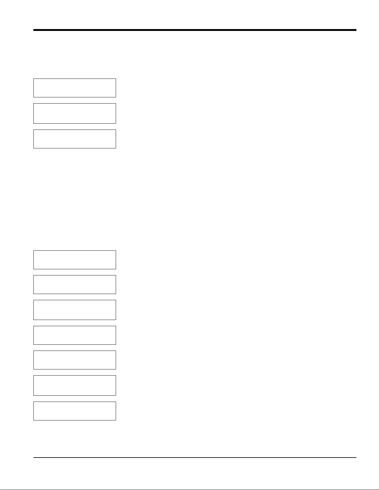
Chapter 5. Advanced Programming
5.9 Manual Offset?
The Manual Offset? option enables you to apply a manually-entered offset (in percent or PPM) to the gas calculations.
FACTORY SETUP MENU
Manual Offset?
FACTORY SETUP MENU
% Offset: [X.XX]:
FACTORY SETUP MENU
Manual Offset?
Press [YES] to apply a manual offset to the gas calculations.
Use the numeric keys to enter the desired value (in % or ppm). Press [YES] to enter
the value, and [YES] again to confirm the entry.
Press [NO] to proceed to the Change AutoCal Limits? option.
5.10Change AutoCal Limits?
The Change AutoCal Limits? option enables you to adjust the error handling limits for auto calibration. (To program
basic auto cal parameters, refer to Auto Cal Parameters on page 42.) The TMO2D has default values for error
handling:
• Total Calibration Drift Limit: 40% of input range (6.40 mA)
• Drift per Calibration Limit: 25% of input range (4.00 mA)
• Verification Mode Drift Limit: 10% of input range (1.6 mA)
FACTORY SETUP MENU
Change AutoCal Limits?
Press [YES] to change the error handling limits for auto calibration.
AUTOCAL DRIFT LIMITS
Edit Tot Drift Limit?
Set Total Cal Drift:
Drift mA [X.XX]:
AUTOCAL DRIFT LIMITS
Edit Tot Drift Limit?
AUTOCAL DRIFT LIMITS
Edit per cal Limit?
Set Max Drift Per Cal:
Drift mA [X.XX]:
AUTOCAL DRIFT LIMITS
Edit per cal Limit?
Press [YES] to edit the total calibration drift limit.
Use the numeric keys to enter the desired limit. Press [YES] to enter the value, and
[YES] again to confirm the entry.
Press [NO] to proceed to the drift per calibration limit.
Press [YES] to edit the drift per calibration limit.
Use the numeric keys to enter the desired limit. Press [YES] to enter the value, and
[YES] again to confirm the entry.
Press [NO] to proceed to the verification mode drift limit.
TMO2D Digital Display User’s Manual 59
Page 68
Chapter 5. Advanced Programming
5.10 Change AutoCal Limits (cont.)
AUTOCAL DRIFT LIMITS
Edit Verification Limit?
Set Verification Limit:
Drift mA [X.XX]:
AUTOCAL DRIFT LIMITS
Edit Verification Limit?
AUTOCAL DRIFT LIMITS
Done?
FACTORY SETUP MENU
Change AutoCal Limits?
FACTORY SETUP MENU
Resume?
Press [YES] to edit the verification mode drift limit.
Use the numeric keys to enter the desired limit. Press [YES] to enter the value, and
[YES] again to confirm the entry.
Press [NO] to exit the verification mode drift limit.
Press [YES] to exit the AutoCal Drift Limits window. (Pressing [NO] returns the
option to the Edit Tot Drift Limit prompt.)
Press [NO] to exit the Change AutoCal Limits? option. (Pressing [YES] returns the
option to the Edit Tot Drift Limit prompt.)
Press [YES] to exit the Factory Setup Menu and resume taking measurements.
(Pressing [NO] returns the menu to the Set Significant Digits? prompt.)
60 TMO2D Digital Display User’s Manual
Page 69

Chapter 6. Specifications
Chapter 6. Specifications
6.1 Performance
Accuracy: ±0.1% of span (electronics only)
Ambient Temperature Effect: ±0.05% of full scale per °F (°C)
6.2 Functional
Analog Output: Dual, isolated 0/4-20 mA, 500 ohm maximum, 12-bit resolution, field programmable
Alarms:
• Standard: Two Form C, SPDT, 2 A maximum @ 115 VAC, field programmable, 0.01% setpoint resolution, 0.05%
of span dead band
• Optional: Two hermetically sealed relays for Class I, Division 2 hazardous (classified) locations
• Two standard or hermetically sealed relays for automatic calibration (Auto Cal)
Digital Output: RS-232C serial port
Display: 2-line x 24-character backlit LCD
Analog Input:
• One 4-20 mA from any transmitter
• Optional second 4-20 mA input
Power: 100/115/230/240 VAC ±10%, 50/60 Hz, 35 watts max., provides 24 VDC, 1.2 A max. to transmitter
Fuses:
• 110/120 VAC: 0.5 A, Slo-Blo
• 220/240 VAC: 0.25 A, Slo-Blo.
Temperature:
• Operating: 0 to +50°C (+32 to +122°F)
• Storage: -20 to +70°C (-4 to +158°F)
TMO2D Digital Display User’s Manual 61
Page 70

Chapter 6. Specifications
6.3 Physical
Dimensions (H x W x D):
• Rack Mount: 5.25 x 19 x 9.25 in. (133 x 483 x 235 mm)
• Bench Mount: 5.25 x 9 x 9.25 in. (133 x 229 x 235 mm)
• Panel Mount: 5.25 x 9 x 9.25 in. (133 x 229 x 235 mm)
• Weatherproof, fiberglass: 11.25 x 9.38 x 4.38 in. (286 x 238 x 111 mm)
• Weatherproof, stainless steel: 11:37 x 8.93 x 4.00 in. (289 x 227 x 102 mm)
Weight:
• Rack Mount: 5.4 lb (2.4 kg)
• Bench Mount: 7.4 lb (3.4 kg)
• Panel Mount: 4.7 lb (2.1 kg)
• Weatherproof, fiberglass: 6.5 lb (3.0 kg)
• Weatherproof, stainless steel: 12 lb (5.4 kg)
Environmental:
• Rack, Bench, Panel Mount: General-purpose
• Weatherproof, fiberglass: NEMA 4X, IP65
• Weatherproof, stainless steel: NEMA 4X
• Explosion-proof: Consult factory.
European Compliance:
This unit complies with EMC Directive 2004/108/EC and 2006/95/EC Low Voltage Directive. (Installation
Category II, Pollution Degree 2)
62 TMO2D Digital Display User’s Manual
Page 71
6.4 Ordering Information
ABCDEF
TMO2D
B - Design Package
1. Rack Mount*
2. Bench Mount
3. Panel Mount*
4. Weatherproof enclosure, fiberglass , NEMA 4X
5. Weatherproof (NEMA 4X, stainless steel*
Chapter 6. Specifications
TMO2D Display
C - Power
1. 100 VAC, 50-60 Hz
2. 115 VAC, 50-60 Hz
3. 230 VAC, 50-60 Hz
4. 240 VAC, 50-60 Hz
D - Output
2. Dual, isolated 0/4-20 mA
E - Alarm Relays
1. Dual alarm relays (standard)
2. Dual alarm relays, hermetically-sealed for Class I, Div. 2
3. Dual alarm relays and autocal**
4. Dual alarm relays and autocal**, hermetically-sealed for Class I, Div. 2
F-Analyzer
1. For use with oxygen analyzer
2. For use with gas analyzer
*Approved for Division 2 with Division 2 alarms
**Dual automatic calibration relays (autocal)
TMO2D Digital Display User’s Manual 63
Page 72
Chapter 6. Specifications
64 TMO2D Digital Display User’s Manual
Page 73

Appendix A. Outline and Installation Drawings
Appendix A. Outline and Installation Drawings
• Figure 16: Rock Mount Outline
• Figure 17: Bench Mount Outline
• Figure 18: Panel Mount Outline
• Figure 19: Panel and Rack Mounting Dimensions
• Figure 20: Fiberglass Weatherproof Outline
• Figure 21: Stainless Steel Weatherproof Outline
• Figure 22: Oxygen Display PC Board Assembly
• Figure 23: Oxygen Display PC Board Schematic, sht 1
• Figure 24: Oxygen Display PC Board Schematic, sht 2
• Figure 25: Oxygen Display PC Board Schematic, sht 3
TMO2D Digital Display User’s Manual 65
Page 74

Appendix A. Outline and Installation Drawings
66 TMO2D Digital Display User’s Manual
Page 75
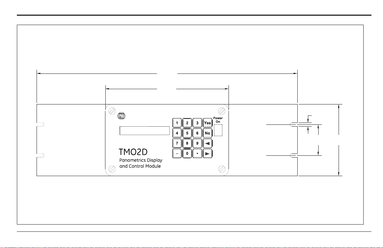
19.00 (483)
9.00 (229)
0.25 (6.4)
2.25
(57)
5.25
(133)
Notes:
1. Dimensions are in inches (millimeters).
2. All dimensions are reference.
3. Depth = 9.85 (250)
Appendix A. Outline and Installation Drawings
TMO2D Digital Display User’s Manual 67
Figure 16: Rack Mount Outline (ref. dwg #712-220)
Page 76
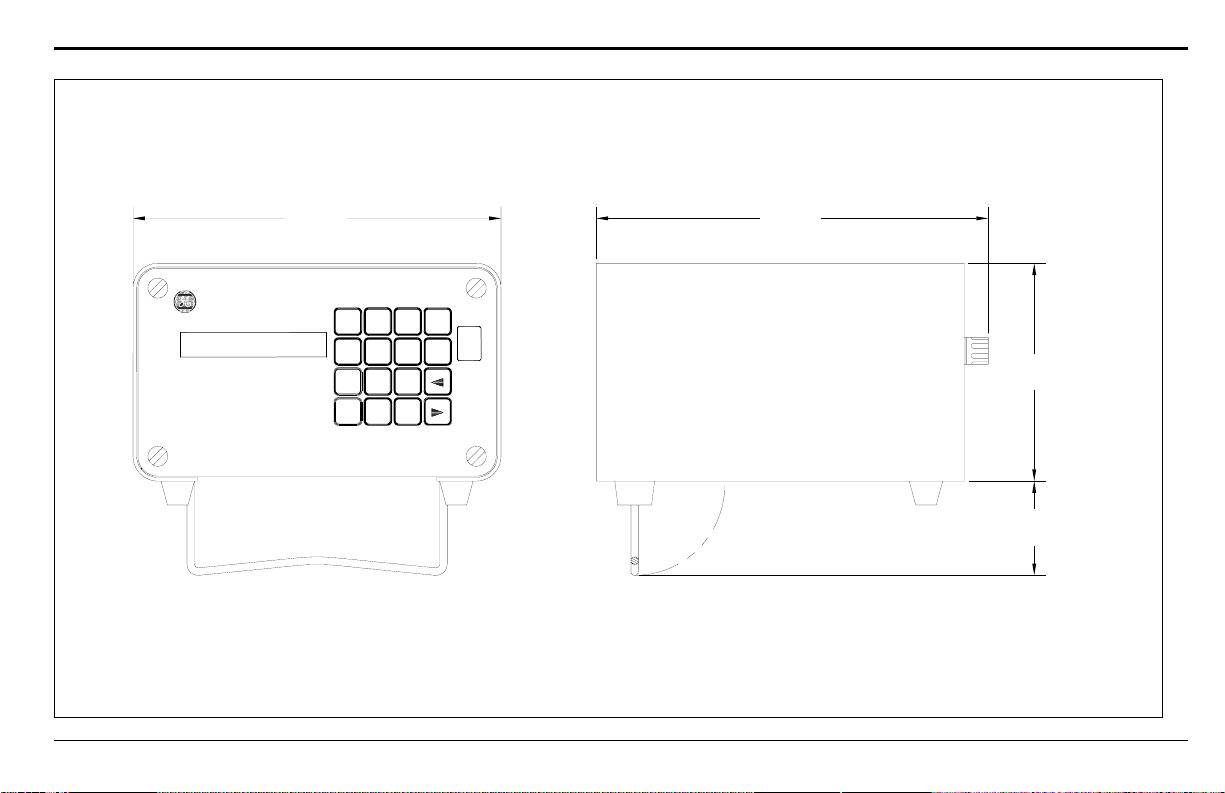
9.00 (229) 9.85 (250)
5.25
(133)
2.27
(58)
Notes:
1. Dimensions are in inches (millimeters).
2. All dimensions are reference.
TMO2D
P anametrics Dis play
and C ontrol Module
–
7
4
1
0
8
5
2
•
9
63No
Yes
Power
On
Appendix A. Outline and Installation Drawings
Figure 17: Bench Mount Outline (ref. dwg #712-221)
TMO2D Digital Display User’s Manual 68
Page 77
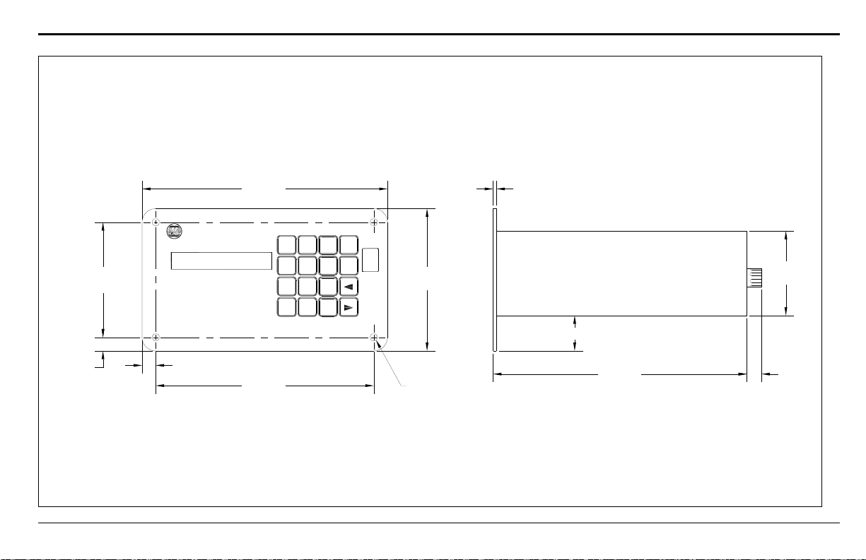
Appendix A. Outline and Installation Drawings
9.00 (229)
5.22
(133)
4.22
(107)
0.50
(13)
0.50 (13)
8.00 (203)
0.265 (6.7) Dia
(4 places)
1.03 (26)
3.10
(79)
0.125 (3.2)
Note: Dimensions are in inches (millimeters).
TMO2D
P aname trics D is play
and C ontrol M odule
–
7
4
1
0
8
5
2
•
9
63No
Yes
Power
On
9.19 (233) 0.50 (13)
TMO2D Digital Display User’s Manual 69
Figure 18: Panel Mount Outline (ref. dwg #712-222)
Page 78
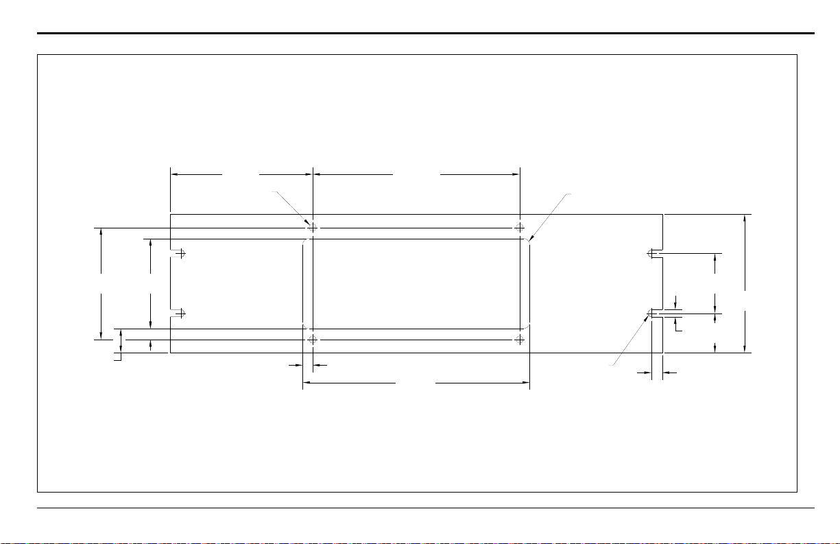
Appendix A. Outline and Installation Drawings
4.220
(107.2)
3.40
(86)
.410 (10.4)
0.91
(23)
0.375 (9.5)
5.50 (140)
.264 - .271 Dia
4 places
(6.7 - 6.9)
8.000 (203.2)
8.75 (222)
0.19 (5) R typ.
0.25
(6)
ref.
2.250
(57.2)
1.48
(38)
5.22
(133)
0.43 (11)
typ. both ends
.125 (3.2) R
4 places
Note: Dimensions are in inches (millimeters).
TMO2D Digital Display User’s Manual 70
Figure 19: Panel and Rack Mounting Dimensions (ref. dwg #712-255)
Page 79
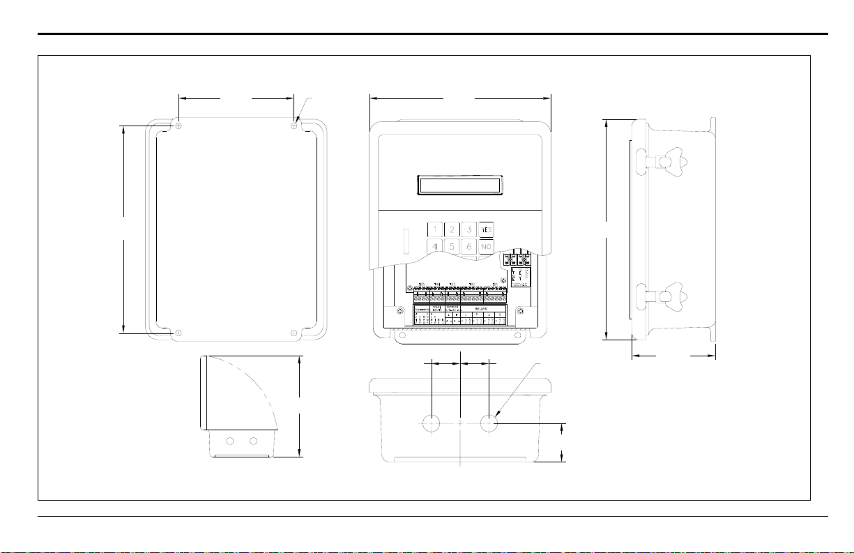
Appendix A. Outline and Installation Drawings
6.00 (152)
Ref.
.250 (6.4) Dia.
Ref. 4 places
9.38 (238)
11.43
(290)
4.35 (110)
1.50
(38)
1.50
(38)
C
L
0.88 (22) Dia. thru
2 places
2.00
(51)
8.72
(116)
0.75
(273)
Ref.
NOT TO SCALE
Note: Dimensions are in inches (millimeters).
TMO2D Digital Display User’s Manual 71
Figure 20: Fiberglass Weatherproof Outline (ref. dwg #701-030)
Page 80
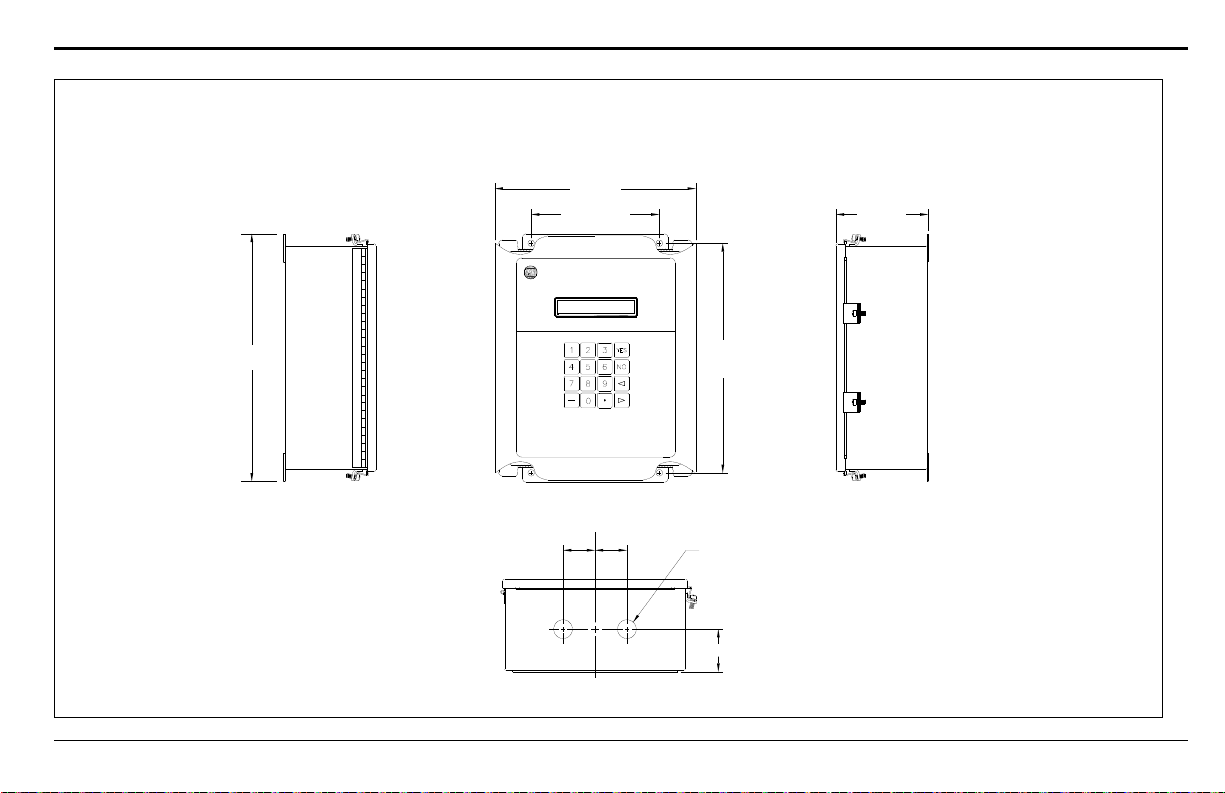
11.37
(289)
6.00 (152) Ref.
8.93 (227)
10.75
(273)
Ref.
4.00 (102)
2.00 (51)
1.50
(38)
1.50
(38)
C
L
0.88 (22) Dia. thru
2 places
Note: Dimensions are in inches (millimeters).
TMO2D
Pana metrics D is pla y
and Control Module
Appendix A. Outline and Installation Drawings
TMO2D Digital Display User’s Manual 72
Figure 21: Stainless Steel Weatherproof Outline (ref. dwg #712-1123)
Page 81
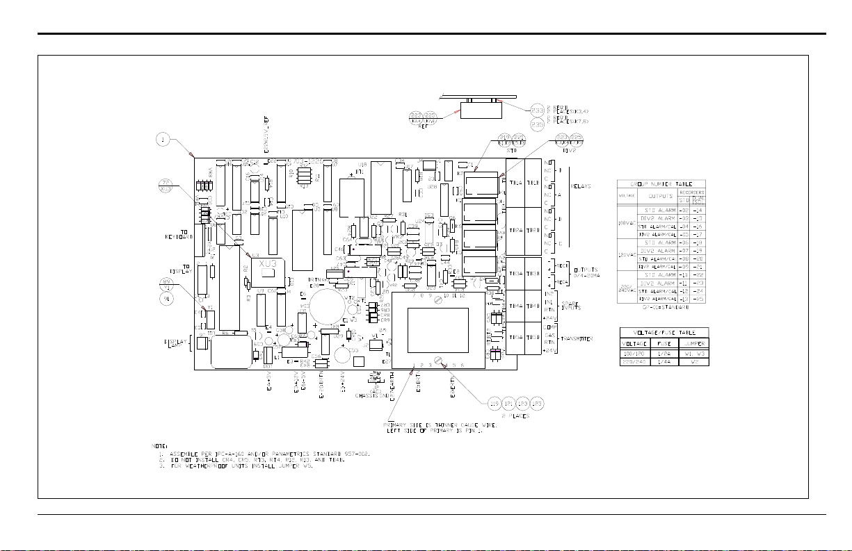
Appendix A. Outline and Installation Drawings
Figure 22: Oxygen Display PC Board Assembly (ref. dwg #703-1226)
TMO2D Digital Display User’s Manual 73
Page 82
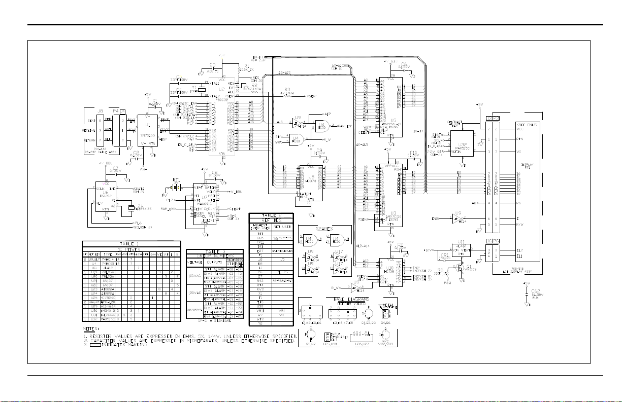
Appendix A. Outline and Installation Drawings
Figure 23: Oxygen Display PC Board Schematic (ref. dwg #700-1226, sht 1)
TMO2D Digital Display User’s Manual 74
Page 83
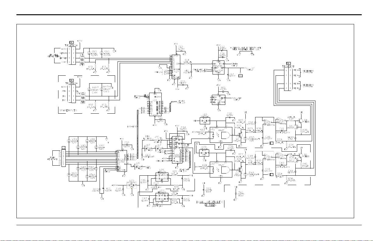
Appendix A. Outline and Installation Drawings
Figure 24: Oxygen Display PC Board Schematic (ref. dwg #700-1226, sht 2)
TMO2D Digital Display User’s Manual 75
Page 84
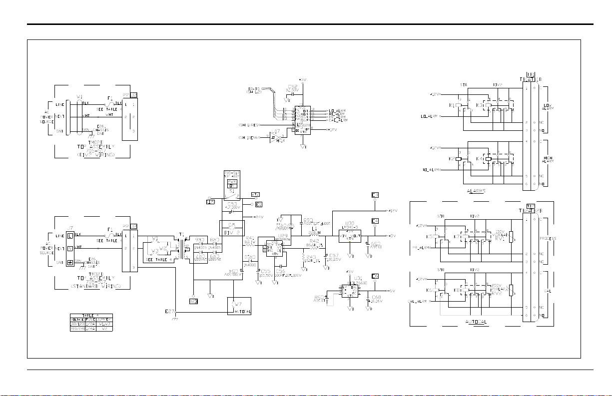
Appendix A. Outline and Installation Drawings
Figure 25: Oxygen Display PC Board Schematic (ref. dwg #700-1226, sht 3)
TMO2D Digital Display User’s Manual 76
Page 85

Appendix B. Menu Maps
• Figure 26: Main Menu: Setup and Outputs
• Figure 27: Main Menu: Relays and Tests
• Figure 28: Main Menu: Calibration Menu
• Figure 29: Main Menu: Calibration (AutoCal Param.), System Log & Resume
• Figure 30: Factory Setup Menu
Appendix B. Menu Maps
TMO2D Digital Display User’s Manual 77
Page 86

Appendix B. Menu Maps
78 TMO2D Digital Display User’s Manual
Page 87
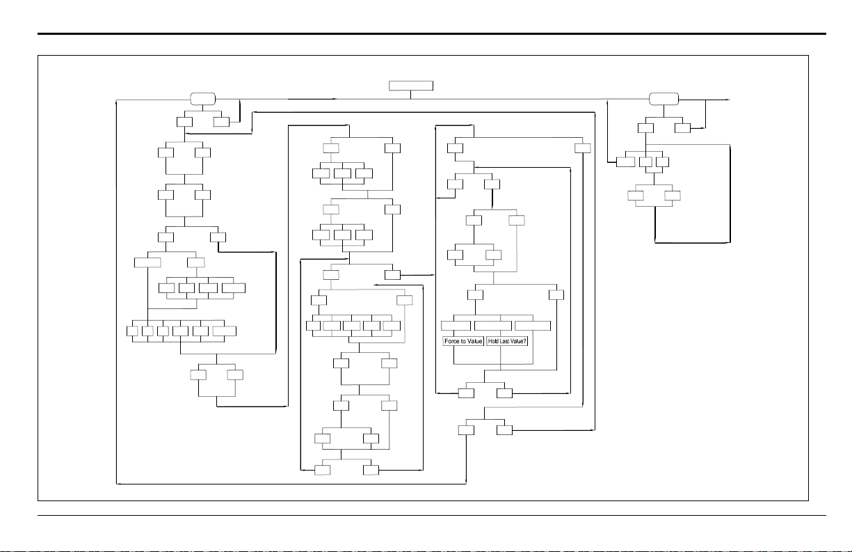
Appendix B. Menu Maps
Setup
Yes No
Yes No
Enter time:
[HH:MM]
Set Time?
Yes No
Enter date:
[MM:DD:YY]
Set Date?
Yes No
Set Gas/Units/Scaling?
Percent PPM
10 1,000100 10,000
Input Range Maximum PPM
O2 OTHERSO2H2 N2 CO2
Input Gas
Gas Label
Yes No
Remain ON
Min [X]
Set Backlight?
Yes No
Set Contrast?
Adjust LCD Contrast
Incr Decr Done
Yes No
Set Display?
Display Compensation
None Pres Bkgd
Yes No
Set Communications?
Set Baud Rate?
Yes No
Select Baud Rate?
300 1200 960048002400
Yes No
Set Data Interval
[XXX]
Set Update Rate?
Yes No
Print Time
Stamp?
Set Time Stamp?
Yes No
Yes No
Done?
Yes No
Set Error Handling?
No Yes
Handling?
Yes No
Response?
Enable Error
Set Display
Yes No
System Error?
Display
Yes No
Set Output Response?
No Effect Force Low?Force High?
Output B Value
Output A Value
Select Output Effect?
Yes No
Done?
Yes No
Done?
Outputs?
Yes No
Done BA
0-20 4-20
A (or B) Output Range (mA)
%Gas [XX.XX]
Output A (or B) 4 mA Value
%Gas [XXX.XX]
Output A (or B) 20mA Value
Select Output to Set:
Note: After entering numeric values, press the
[YES] key twice, once to enter and once
to confirm the new value.
MAIN MENU
NO 1 2 3
TMO2D Digital Display User’s Manual 79
Figure 26: Main Menu: Setup and Outputs
Page 88
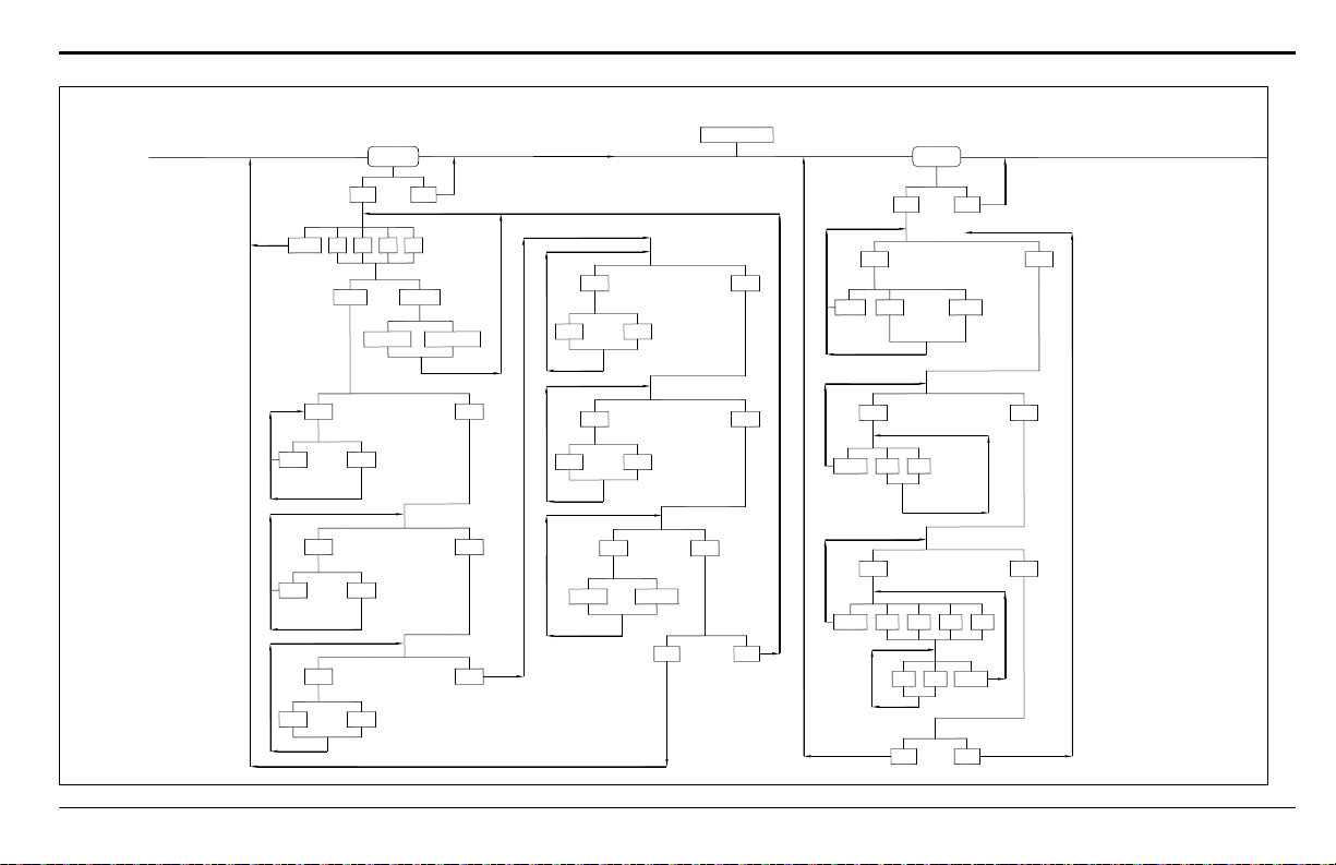
Relays?
Yes No
Select Relay to Set
Alarm Autocal
Relay Type
No
Set Low Alarm Function
ADone B C
Yes No
Done?
Yes No
Done?
Tests?
Yes No
Note: After entering numeric values, press the
[YES] key twice, once to enter and once
to confirm the new value.
MAIN MENU
NO 1 2 3
D
Proc/Cal Zero/Span
Yes
No Yes
Trip on low value
Alarm X, Low Setpoint
PPM/%Gas [X.XX]
Yes
No Yes
Trip on high value
Alarm X, High Setpoint
PPM/%Gas [X.XX]
Yes
No Yes
Trip on System Faults
No
Set High Alarm Function
No
Set System Fault Action?
No
Set Cal Error Action?
Yes
No Yes
Trip on Auto Cal Errors?
Yes
No Yes
Trip on New Cal Data?
Yes
Normal Failsafe
Failsafe?
No
Set Cal Occurred Action?
No
Normal/Failsafe Mode?
No
DVM Tests?
Yes
Done Comp
Select DVM Input:
Gas DVM Test
Press Any Key
Yes
Done B
Select Output to Test:
Set Output A/B to:
%Gas [XX.XX]
No
Output Test?
Gas
Comp DVM Test
Press Any Key
A
Yes
Done D
Select Relay to Test:
Turn Relay X:
No
Relays Test?
A B C
On Off Done
Appendix B. Menu Maps
TMO2D Digital Display User’s Manual 80
Figure 27: Main Menu: Relays and Tests
Page 89
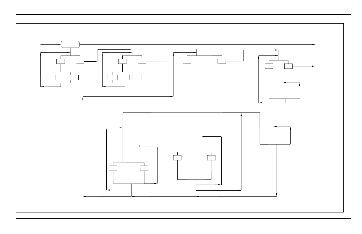
Calibration
Yes No
Fast Damped
Select Response?
Set System Response
Yes No
None
Select Compensation?
Select Compensation
Pres Bkgd
Yes No
Gas Calibration?
(If Pressure Compensation Selected) (If Background Compensation Selected) (If No Compensation Selected)
Pressure Grid Entry
# of Curves [X]
O2 Grid Entry
# of Curves [X]
Gas Grid Entry
# of Points [X]:
Curve #1
mmHg [X.X]
O2 Grid Entry
# of Points [X]:
Point #1
%ppm Gas [XX.XX]
Pressure Grid Entry
# of Points [X]
Point #1
%O2 [XX.XX]
XXX %O2
Gas mA [X.XX]
Point #1
%O2 [X.XX]
X.XX %O2, Curve #1
Enter Point?
X.XX %O2, X.X mmHg
Enter Point?
Yes No
X.XX %O2, Curve #1
O2 mA [X.XX]
X.XX %O2, Curve #1
Bkgd mA [X.XX]
Yes No
X.XX %O2,
X.X mmHg
O2 mA [X.XX]
Repeat for
X Curves
Repeat for
X Points
Repeat for
X Points
Repeat for
X Curves
Repeat for
X Points
Yes No
Pressure Calib?
Pres Xducer Curve Entry
# of Points [X]:
Point #1
mmHg [X.X]
Point #1
Press mA [X.XX]
Repeat for
X Points
Note: After entering numeric values, press
[YES] twice, once to enter and once
to confirm the new value.
Appendix B. Menu Maps
Figure 28: Main Menu: Calibration Menu
TMO2D Digital Display User’s Manual 81
Page 90
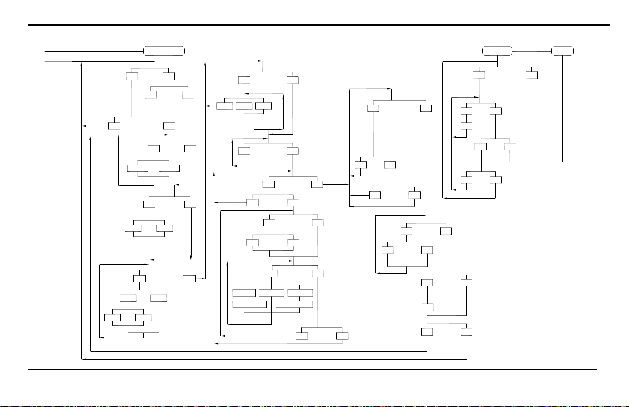
Appendix B. Menu Maps
(Calibration Menu)
Yes No
Disabled Enabled
System Log
Note: After entering numeric values, press the
[YES] key twice, once to enter and once
to confirm the new v alue.
Yes
1 Gas 2 Gas
Set AutoCal Type:
No
Set AutoCal Mode?
No Yes
Enable AutoCal:
Auto Cal Parameters?
Yes No
Set Auto
Verification?
Auto Verification
Hours Days
Yes No
Select Autocal
Interval
AutoCal Interval
Hours/Days [XX]:
AutoCal at Time:
HH.MM [XX.XX]
Set Time Interval?
Offset Span
Cal Type
Yes No
Set Cal
Gas Data?
Calibration Gas
Done SpanZero
%/ppm Gas
MM.SS
Yes No
Set Settling Time?
Settling Time:
MM.SS [XX.XX]
Yes No
Set Error Handling?
No Yes
Enable Error Handling
Yes No
Set Display Response?
Yes No
Display AutoCal Error?
Yes No
Set Output Response?
No Effect Force Low
Select Output Effect:
Force High
Hold Last ValueForce to Value
Output B [X.XX]
Output A [X.XX]
No Yes
Done?
Yes No
Done?
(Main Menu
Calibration)
(Calibration
Select
Response)
Yes No
Perform AutoCal?
Yes No
Abort Autocal?
Zero Gas is ON...
Span Gas is ON...
Yes No
Abort Settling?
Settling . . .
Yes No
Yes No
Yes No
Reset Drift?
Reset Drift?
View Drift Curve?
Working . . .
No
Drift Values . . .
(Or "No Points
in Curve")
No Yes
Done?
Resume
Yes No
Yes No
Display System Log?
System Log
No Yes
No
No Yes
Print System Log?
Done?
Printing Log . . .
TMO2D Digital Display User’s Manual 82
Figure 29: Main Menu: Calibration (Auto Cal Param.), System Log, & Resume
Page 91
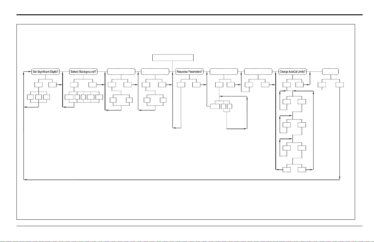
Yes No
2
Tau (up)
[XX.XX]
Resume?
3 4
Yes No Yes No Yes Yes Yes Yes Yes
Manual Offset?LabCal Outputs?Select Tertiary?Select Tracking?
Bkgd N2 CO2SO2H2
On Off On Off
Tau (down)
[XX.XX]
Thresh
[XX.XX]
Smooth
[XX.XX]
Window
[XX.XX]
No
Done A B
No
20 mA output
[X.XX]
4 mA output
[X.XX]
Output
No
% or
ppm Offset
Yes No
Yes No
Yes No
Yes No
No
Tot Drift Limit?
Drift mA
[X.XX]
Drift
per Cal?
Drift mA
[X.XX]
Verification
Limit?
Drift mA
[X.XX]
Done?
Yes NoNo
(Meter resumes
taking
measurements.)
Note: After entering numeric values, press [YES]
twice, once to enter and once to confirm the
new value.
FACTORY SETUP MENU
NO 3 6 9
Appendix B. Menu Maps
TMO2D Digital Display User’s Manual 83
Figure 30: Factory Setup Menu
Page 92
Appendix B. Menu Maps
TMO2D Digital Display User’s Manual 84
Page 93

Index
A
Accuracy, TMO2D Display . . . . . . . . . . . . . . . . . . . 61
Alarms, TMO2D Display. . . . . . . . . . . . . . . . . . . . . 61
Ambient T e mperature Effect . . . . . . . . . . . . . . . . . . 61
Analog Output, TMO2D Display . . . . . . . . . . . . . . . 61
Analog Outputs, Calibrating. . . . . . . . . . . . . . . . . . . 58
Auto Cal Parameters . . . . . . . . . . . . . . . . . . . . . 42, 43
Menu Map. . . . . . . . . . . . . . . . . . . . . . . . . . . . . . 82
Set AutoCal Mode? . . . . . . . . . . . . . . . . . . . . . . . 45
Set Error Handling? . . . . . . . . . . . . . . . . . . . . . . . 47
Set Settling Time? . . . . . . . . . . . . . . . . . . . . . . . . 46
Set Zero Gas? . . . . . . . . . . . . . . . . . . . . . . . . . . . 45
View Drift Curve? . . . . . . . . . . . . . . . . . . . . . . . . 51
AutoCal, Changing Limits . . . . . . . . . . . . . . . . . . . . 59
B
Background Compensation . . . . . . . . . . . . . . . . . . . 40
Backlight, Setting . . . . . . . . . . . . . . . . . . . . . . . . . . 26
Bench Mount, Outline . . . . . . . . . . . . . . . . . . . . . . . 68
C
Cable Requirements
External Compensation
Internal Compensation . . . . . . . . . . . . . . . . . . . . . . 4
TMO2. . . . . . . . . . . . . . . . . . . . . . . . . . . . . . . . . . 4
TMO2-TC. . . . . . . . . . . . . . . . . . . . . . . . . . . . . . 10
XMO2. . . . . . . . . . . . . . . . . . . . . . . . . . . . . . . . . . 7
XMTC . . . . . . . . . . . . . . . . . . . . . . . . . . . . . . . . 12
Calibrating Analog Outputs . . . . . . . . . . . . . . . . . . . 58
Calibration Menu. . . . . . . . . . . . . . . . . . . . . . . . . . . 37
Auto Cal Parameters . . . . . . . . . . . . . . . . . . . 42, 43
Gas Calibration? . . . . . . . . . . . . . . . . . . . . . . . . . 39
Menu Map. . . . . . . . . . . . . . . . . . . . . . . . . . . . . . 81
Pressure Calibration? . . . . . . . . . . . . . . . . . . . . . . 41
Select Compensation? . . . . . . . . . . . . . . . . . . . . . 38
Select Response? . . . . . . . . . . . . . . . . . . . . . . . . . 38
CE Mark Compliance
Requirements for
Change AutoCal Limits? . . . . . . . . . . . . . . . . . . . . . 59
Communications, Setting . . . . . . . . . . . . . . . . . . . . . 27
Connecting TMO2 to TMO2D . . . . . . . . . . . . . . . . . . 4
Contrast, Setting . . . . . . . . . . . . . . . . . . . . . . . . . . . 26
. . . . . . . . . . . . . . . . . . . . . 4
. . . . . . . . . . . . . . . . . . 6, 9, 11, 14
D
Damped Response. . . . . . . . . . . . . . . . . . . . . . . . . . 38
Date, Setting . . . . . . . . . . . . . . . . . . . . . . . . . . . . . . 24
Digital Output, TMO2D Display . . . . . . . . . . . . . . . 61
Dimensions
Bench Mount
Fiberglass Weatherproof. . . . . . . . . . . . . . . . . . . . 71
Panel Mount . . . . . . . . . . . . . . . . . . . . . . . . . . . . 69
Rack Mount. . . . . . . . . . . . . . . . . . . . . . . . . . . . . 67
Stainless Steel Weatherproof. . . . . . . . . . . . . . . . . 72
Display Navigation . . . . . . . . . . . . . . . . . . . . . . . . . 22
Display , Setting. . . . . . . . . . . . . . . . . . . . . . . . . . . . 27
Drift, Resetting . . . . . . . . . . . . . . . . . . . . . . . . . . . . 51
DVM Test? . . . . . . . . . . . . . . . . . . . . . . . . . . . . . . . 35
. . . . . . . . . . . . . . . . . . . . . . . . . . . . 68
E
Entering Data into the User Program. . . . . . . . . . 21, 55
Environmental Compliance . . . . . . . . . . . . . . . . . . . iv
Error Handling, Setting . . . . . . . . . . . . . . . . . . . 29, 30
External Compensation
Cable Requirements
Wiring. . . . . . . . . . . . . . . . . . . . . . . . . . . . . . . . . . 3
. . . . . . . . . . . . . . . . . . . . . . . . 4
F
Factory Setup
Menu Map
Menu Mode. . . . . . . . . . . . . . . . . . . . . . . . . . . . . 55
Program, Entering Data . . . . . . . . . . . . . . . . . . . . 55
Fast Response . . . . . . . . . . . . . . . . . . . . . . . . . . . . . 38
Parameters. . . . . . . . . . . . . . . . . . . . . . . . . . . . . . 57
Features and Capabilities . . . . . . . . . . . . . . . . . . . . . . 1
Fiberglass Weatherproof, Outline . . . . . . . . . . . . . . . 71
Fuses, TMO2D Display . . . . . . . . . . . . . . . . . . . . . . 61
. . . . . . . . . . . . . . . . . . . . . . . . . . . . . . 83
G
Gas Calibration . . . . . . . . . . . . . . . . . . . . . . . . . 39, 40
I
Information Paragraphs . . . . . . . . . . . . . . . . . . . . . . iii
Installation, TMO2D . . . . . . . . . . . . . . . . . . . . . . . . . 3
Internal Compensation
Cable Requirements
Wiring. . . . . . . . . . . . . . . . . . . . . . . . . . . . . . . . . . 3
. . . . . . . . . . . . . . . . . . . . . . . . 4
TMO2D Digital Display User’s Manual 85
Page 94

Index
K
Key Functions. . . . . . . . . . . . . . . . . . . . . . . . . . . . . 22
Keypad for TMO2D . . . . . . . . . . . . . . . . . . . . . . . . 20
L
LabCal Outputs? . . . . . . . . . . . . . . . . . . . . . . . . . . . 58
LCD Display, TMO2D. . . . . . . . . . . . . . . . . . . . 19, 61
M
Manual Offset? . . . . . . . . . . . . . . . . . . . . . . . . . . . . 59
Menu Map
Auto Cal Parameters
Calibration . . . . . . . . . . . . . . . . . . . . . . . . . . . . . 81
Factory Setup . . . . . . . . . . . . . . . . . . . . . . . . . . . 83
Relays and Tests . . . . . . . . . . . . . . . . . . . . . . . . . 80
Setup and Outputs . . . . . . . . . . . . . . . . . . . . . . . . 79
System Log and Resume . . . . . . . . . . . . . . . . . . . 82
Menu Mode . . . . . . . . . . . . . . . . . . . . . . . . . . . . . . 21
Data Collection Status . . . . . . . . . . . . . . . . . . . . . 23
Menu Navigation. . . . . . . . . . . . . . . . . . . . . . . . . . . 23
Menu, Factory Setup . . . . . . . . . . . . . . . . . . . . . . . . 55
Mounting the TMO2D Display. . . . . . . . . . . . . . . . . . 3
. . . . . . . . . . . . . . . . . . . . . . 82
O
Operate Mode . . . . . . . . . . . . . . . . . . . . . . . . . . 21, 55
Outline
Bench Mount
Fiberglass Weatherproof. . . . . . . . . . . . . . . . . . . . 71
Panel Mount . . . . . . . . . . . . . . . . . . . . . . . . . . . . 69
Rack Mount. . . . . . . . . . . . . . . . . . . . . . . . . . . . . 67
Stainless Steel Weatherproof. . . . . . . . . . . . . . . . . 72
Output Test . . . . . . . . . . . . . . . . . . . . . . . . . . . . . . . 36
Outputs Menu . . . . . . . . . . . . . . . . . . . . . . . . . . . . . 30
Menu Map. . . . . . . . . . . . . . . . . . . . . . . . . . . . . . 79
. . . . . . . . . . . . . . . . . . . . . . . . . . . . 68
P
Panel Mount, Outline. . . . . . . . . . . . . . . . . . . . . . . . 69
Physical Specifications . . . . . . . . . . . . . . . . . . . . . . 62
Power, TMO2D Display. . . . . . . . . . . . . . . . . . . . . . 61
Powering Up TMO2 . . . . . . . . . . . . . . . . . . . . . . . . 19
Pressure Calibration?. . . . . . . . . . . . . . . . . . . . . . . . 41
Pressure Compensation . . . . . . . . . . . . . . . . . . . . . . 40
Programming the TMO2D . . . . . . . . . . . . . . . . . . . . 22
R
Rack Mount, Outline . . . . . . . . . . . . . . . . . . . . . . . . 67
Relays Menu. . . . . . . . . . . . . . . . . . . . . . . . . . . . . . 31
Menu Map. . . . . . . . . . . . . . . . . . . . . . . . . . . . . . 80
Relays Test . . . . . . . . . . . . . . . . . . . . . . . . . . . . . . . 36
Reset Drift?. . . . . . . . . . . . . . . . . . . . . . . . . . . . . . . 51
Response Parameters (for Fast Response) . . . . . . . . . 57
Resume Menu Map . . . . . . . . . . . . . . . . . . . . . . . . . 82
Return Policy . . . . . . . . . . . . . . . . . . . . . . . . . . . . . 89
RS-232C Serial Port
Correspondence of Keys
Remote Operation . . . . . . . . . . . . . . . . . . . . . . . . 20
. . . . . . . . . . . . . . . . . . . . 20
S
Safety
Auxiliary Equipment
General Issues . . . . . . . . . . . . . . . . . . . . . . . . . . . iii
Personal Equipment . . . . . . . . . . . . . . . . . . . . . . . iii
Select Background?. . . . . . . . . . . . . . . . . . . . . . . . . 56
Select Compensation? . . . . . . . . . . . . . . . . . . . . . . . 38
Select Response?. . . . . . . . . . . . . . . . . . . . . . . . . . . 38
Select Tracking? . . . . . . . . . . . . . . . . . . . . . . . . . . . 57
Set AutoCal Mode? . . . . . . . . . . . . . . . . . . . . . . . . . 45
Set Error Handling?. . . . . . . . . . . . . . . . . . . . . . . . . 47
Set Settling Time?. . . . . . . . . . . . . . . . . . . . . . . 46, 47
Set Significant Digits? . . . . . . . . . . . . . . . . . . . . . . . 56
Set Span Gas? . . . . . . . . . . . . . . . . . . . . . . . . . . . . . 46
Set Time Interval?. . . . . . . . . . . . . . . . . . . . . . . . . . 44
Set Zero Gas? . . . . . . . . . . . . . . . . . . . . . . . . . . . . . 45
Setup Menu. . . . . . . . . . . . . . . . . . . . . . . . . . . . . . . 23
Menu Map. . . . . . . . . . . . . . . . . . . . . . . . . . . . . . 79
Set Backlight? . . . . . . . . . . . . . . . . . . . . . . . . . . . 26
Set Communications?. . . . . . . . . . . . . . . . . . . . . . 27
Set Contrast? . . . . . . . . . . . . . . . . . . . . . . . . . . . . 26
Set Date?. . . . . . . . . . . . . . . . . . . . . . . . . . . . . . . 24
Set Display? . . . . . . . . . . . . . . . . . . . . . . . . . . . . 27
Set Error Handling? . . . . . . . . . . . . . . . . . . . . 29, 30
Set Time? . . . . . . . . . . . . . . . . . . . . . . . . . . . . . . 24
Specifications
Physical
Stainless Steel Weatherproof, Outline . . . . . . . . . . . . 72
System Log Menu Map . . . . . . . . . . . . . . . . . . . . . . 82
. . . . . . . . . . . . . . . . . . . . . . . . . . . . . . . 62
. . . . . . . . . . . . . . . . . . . . . . iii
86 TMO2D Digital Display User’s Manual
Page 95

Index
T
Temperature, TMO2D Display. . . . . . . . . . . . . . . . . 61
Tests Menu . . . . . . . . . . . . . . . . . . . . . . . . . . . . . . . 34
Menu Map. . . . . . . . . . . . . . . . . . . . . . . . . . . . . . 80
Output Test . . . . . . . . . . . . . . . . . . . . . . . . . . . . . 36
Relays Test . . . . . . . . . . . . . . . . . . . . . . . . . . . . . 36
Time, Setting. . . . . . . . . . . . . . . . . . . . . . . . . . . . . . 24
TMO2 Transmitter
Cable Requirements
Powering Up . . . . . . . . . . . . . . . . . . . . . . . . . . . . 19
TMO2D
Configurations
Installation . . . . . . . . . . . . . . . . . . . . . . . . . . . . . . 3
LCD Display . . . . . . . . . . . . . . . . . . . . . . . . . . . . 19
Wiring to Other Components . . . . . . . . . . . . . . . . 15
TMO2D Display
Accuracy
Alarms . . . . . . . . . . . . . . . . . . . . . . . . . . . . . . . . 61
Ambient Temperature. . . . . . . . . . . . . . . . . . . . . . 61
Analog Output. . . . . . . . . . . . . . . . . . . . . . . . . . . 61
Digital Output . . . . . . . . . . . . . . . . . . . . . . . . . . . 61
Dimensions . . . . . . . . . . . . . . . . . . . . . . . . . . . . . 62
Environmental. . . . . . . . . . . . . . . . . . . . . . . . . . . 62
European Compliance . . . . . . . . . . . . . . . . . . . . . 62
Fuses. . . . . . . . . . . . . . . . . . . . . . . . . . . . . . . . . . 61
Key Functions . . . . . . . . . . . . . . . . . . . . . . . . . . . 22
Keypad . . . . . . . . . . . . . . . . . . . . . . . . . . . . . . . . 20
LCD Display . . . . . . . . . . . . . . . . . . . . . . . . . . . . 61
Mounting . . . . . . . . . . . . . . . . . . . . . . . . . . . . . . . 3
Ordering Information . . . . . . . . . . . . . . . . . . . . . . 63
Physical Specifications. . . . . . . . . . . . . . . . . . . . . 62
Power . . . . . . . . . . . . . . . . . . . . . . . . . . . . . . . . . 61
Programming. . . . . . . . . . . . . . . . . . . . . . . . . . . . 22
Temperature . . . . . . . . . . . . . . . . . . . . . . . . . . . . 61
Weight . . . . . . . . . . . . . . . . . . . . . . . . . . . . . . . . 62
TMO2-TC Cable Requirements . . . . . . . . . . . . . . . . 10
TMO2-TC Transmitter
Wiring to TMO2D
Tracking . . . . . . . . . . . . . . . . . . . . . . . . . . . . . . . . . 57
. . . . . . . . . . . . . . . . . . . . . . . . . . . . . . . 61
. . . . . . . . . . . . . . . . . . . . . . . . 4
. . . . . . . . . . . . . . . . . . . . . . . . . . . . 3
. . . . . . . . . . . . . . . . . . . . . . . . 10
V
View Drift Curve? . . . . . . . . . . . . . . . . . . . . . . . . . . 51
W
Warranty. . . . . . . . . . . . . . . . . . . . . . . . . . . . . . . . . 89
WEEE Directive . . . . . . . . . . . . . . . . . . . . . . . . . . . iv
Wiring
External Compensation
Internal Compensation . . . . . . . . . . . . . . . . . . . . . . 3
TMO2D to Other Components . . . . . . . . . . . . . . . 15
. . . . . . . . . . . . . . . . . . . . . 3
X
XMO2 Cable Requirements . . . . . . . . . . . . . . . . . . . . 7
XMTC Cable Requirements. . . . . . . . . . . . . . . . . . . 12
XMTC Transmitter
Wiring to TM O2D
. . . . . . . . . . . . . . . . . . . . . . . . 12
U
Update Rate in Setup Menu . . . . . . . . . . . . . . . . . . . 28
User Program, Entering Data . . . . . . . . . . . . . . . 21, 55
TMO2D Digital Display User’s Manual 87
Page 96

Index
88 TMO2D Digital Display User’s Manual
Page 97

Warranty
Warranty
Each instrument manufactured by GE Sensing is warranted to be free from defects in material and workmanship.
Liability under this warranty is limited to restoring the instrument to normal operation or replacing the instrument, at
the sole discretion of GE Sensing. Fuses and batteries are specifically excluded from any liability. This warranty is
effective from the date of delivery to the original purchaser. If GE Sensing determines that the equipment was
defective, the warranty period is:
• one year from delivery for electronic or mechanical failures
• one year from delivery for sensor shelf life
If GE Sensing determines that the equipment was damaged by misuse, improper installation, the use of unauthorized
replacement parts, or operating conditions outside the guidelines specified by GE Sensing, the repairs are not covered
under this warranty.
The warranties set forth herein are exclusive and are in lieu of all other warranties whether
statutory, express or implied (including warranties or merchantability and fitness for a
particular purpose, and warranties arising from course of dealing or usage or trade).
Return Policy
If a GE Sensing instrument malfunctions within the warranty period, the following procedure must be completed:
1. Notify GE Sensing, giving full details of the problem, and provide the model number and serial number of the
instrument. If the nature of the problem indicates the need for factory service, GE Sensing will issue a RETURN
AUTHORIZATION NUMBER (RAN), and shipping instructions for the return of the instrument to a service
center will be provided.
2. If GE Sensing instructs you to send your instrument to a service center, it must be shipped prepaid to the authorized
repair station indicated in the shipping instructions.
3. Upon receipt, GE Sensing will evaluate the instrument to determine the cause of the malfunction.
Then, one of the following courses of action will then be taken:
• If the damage is covered under the terms of the warranty , the i nstrument will be repaired at no cost to the owner and
returned.
• If GE Sensing determines that the damage is not covered under the terms of the warranty, or if the warranty has
expired, an estimate for the cost of the repairs at standard rates will be provided. Upon receipt of the owner’s
approval to proceed, the instrument will be repaired and returned.
TMO2D Digital Display User’s Manual 89
Page 98

Warranty
90 TMO2D Digital Display User’s Manual
Page 99

GE
Sensing
DECLARATION
OF
CONFORMITY
DOC-0005, Rev. A
We, GE Sensing
1100 Technology Park Drive
Billerica, MA 01821
USA
declare under our sole responsibility that the
TMO2D Display and Control Module
to which this declaration relates, is in conformity with the following standards:
• EN 61326-1: 2006, Class A, Table 2, Industrial Locations
• EN 61010-1: 2001, Overvoltage Category II, Pollution Degree 2
following the provisions of the 2004/108/EC EMC and 2006/95/EC Low Voltage Directives.
The unit listed above and any ancillary equipment supplied with it do not bear CE marking for the Pressure
Equipment Directive, as they are supplied in accordance with Article 3, Section 3 (sound engineering practices and
codes of good workmanship) of the Pressure Equipment Directive 97/23/EC for DN<25.
Billerica - August 2010
Issued Mr. Gary Kozinski
Certification & Standards, Lead Engineer
Page 100

 Loading...