

Page 1
GE
g
READ THOROUGHLY BEFORE INSTALLING
Lighting Solutions
WARNING
Risk of electric shock
• Turn power off before servicing
– see instructions
WARNING
Risk of fire
• Use supply wire specified on
nameplate
GENERAL
This luminaire is designed for outdoor lighting applications,
and should not be used in areas of limited ventilation, or in high
ambient temperature enclosures. For optimum performance, it
should be installed and maintained according to the following
recommendations.
UNPACKING
This luminaire has been properly packed so that no parts
should have been damaged during transit. Inspect to confirm.
INSTALLATION
This luminaire has several mounting arrangements - adjustable
pole-top tenon mounting and two horizontal slipfitters. The nonadjustable version allows for mounting to 2-3/8” OD mounting
arms. The adjustable version is equipped with two pipe clamps and
four mounting bolts. The adjustable, tenon mounting adapter has
two ranges of adjustments. See section A for specific mounting
instruction.
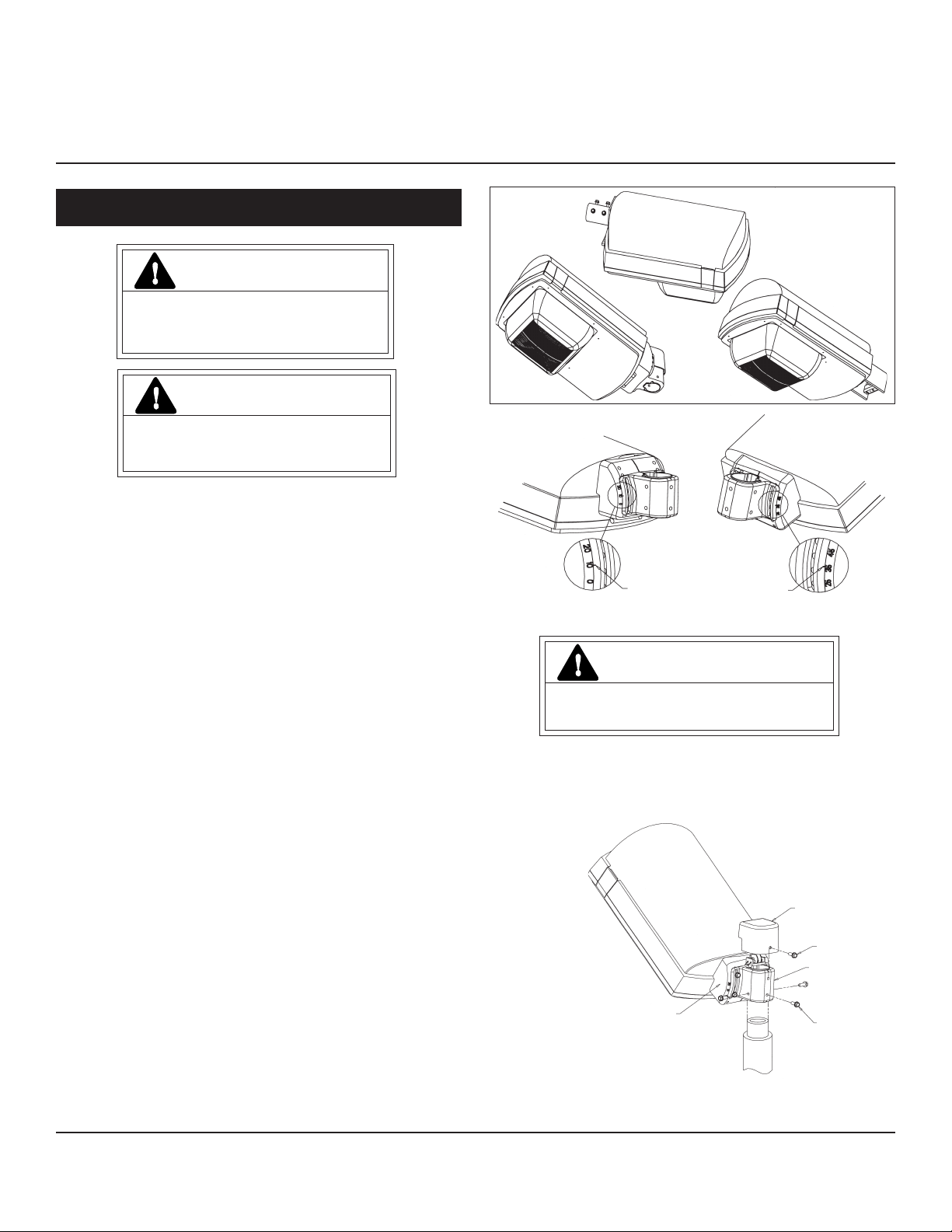
If ordered with the adjustable tenon mounting it has been
shipped as ordered in either the low or high position and exact
angular setting can be accomplished in the field. Verify that the
aiming indicator is on the appropriate side of the slip fitter adapter
for the desired tilt (see Figure 1). For ease of installation, it is
recommended that adjustment to tilt be done for before mounting.
Four slipfitter bolts should be separated as far as possible in the slot
and torque to 10-12 ft-lbs.
Caution: Correct tightening of bolts is important to
ensure proper function of system.
GEH-5944D
INSTRUCTIONS
Tiger™ Fixture
250-400 Watt
Figure 1
A. MOUNTING
AIMING INDICATOR AIMING INDICATOR
CAUTION
Unit will fall if not installed properly
• Follow installation instructions
For adjustable tenon mounting insert 2-inch tenon into the
bottom opening of slip fitter until it rest on center stop. Secure in
place by tightening (3) 3/8” slip fitter mounting bolts. Torque
bolts to 10-12 ft-lbs. Remove cover, connect customer wiring to
luminaire wiring or optional terminal board (See Figure 2).
COVER
COVER SCREW
SLIPFITTER
If aiming indicator is not on the desired side, remove the bolts
securing slip fitter to adapter, cover, terminal board, and slip
fitter mounting bolts. Invert adapter to desired orientation.
Adjust tilt to desired position and secure 3/8” bolts. Reattach the
terminal board, and cover to the top of slip fitter, and the three
mounting bolts in the bottom.
These instructions do not purport to cover all details or variations in equipment nor to provide for every possible contingency to be met in connection with installation, operation or
maintenance. Should further information be desired or should particular problems arise which are not covered sufficiently for the purchaser’s purposes, the matter should be referred
to GE Lighting Solutions.
Figure 2
For luminaires equipped with non-adjustable slipfitter, install
luminaire on the 2-3/8” OD arm and tighten four set-screws (see
Figure 3). Torque screws 10-12 ft-lbs.
SLIPFITTER ADAPTER
(3) MOUNTING SCREWS
Page 2
PIPE CLAMPS
SET SCREWS
Figure 3
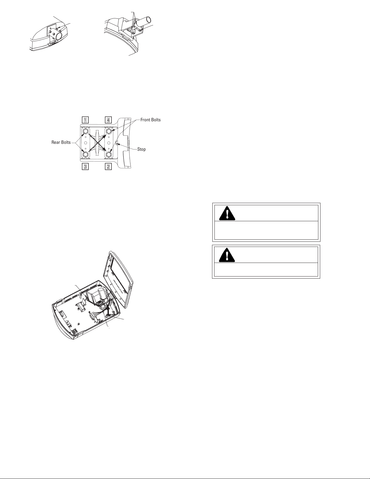
For luminaires equipped with the adjustable slipfitter, install
luminaire on the 2-3/8” OD arm. Arm should be in contact with
“stop” located on the upper front surface of the slipfitter (see
Figure 5). The edges of both pipe clamps must be fully seated
on the arm.
Tighten rear bolts equally to bring leveling ball to center (if
so equipped) or until top housing is level. Tighten front bolts
equally to a torque of 5-12 foot-pounds. Tighten rear bolts to a
torque of 10-20 foot-pounds. Confirm torque using a crossing
pattern (see Figure 5)
Figure 4
BOLTS
Figure 5
B. WIRING
Make all electrical connections in accordance with all
applicable code requirements (National Electrical Code,
Canadian Electrical Code and applicable local Codes).
Verify that supply voltage is correct by comparing it to nameplate.
Supply wiring entering from pole to interior terminal board
must be routed through the wiring clips and maintain one-
half inch (1/2”) (113mm) minimum spacing to SnapDrive (see
Figure 6).
Connect ground lead to the green lead, green ground screw
on housing or terminal block provided.
IF MULTIVOLT (120/208/240/277 volts):
Connect the tray mounted ballast lead with the insulated
terminal to the desired voltage terminal as indicated on the
ballast terminal nameplate.
IF MULTI-WATT
Tray mounted multi-watt ballasts are available in various
combinations of wattage. See wiring instructions on wiring tag
inside the luminaire.
The SnapDrive is equipped with a multi-volt ballast. Ballast
has been wired to the voltage indicated on the nameplate. Verify
that supply voltage is correct by comparing it to nameplate. If
another voltage is desired, place the voltage selection jumper onto
the appropriate voltage position as indicated on the wiring
diagram. Optional features such as fusing, switched quartz safety
lights and photocontrols are voltage specific. Do not change
jumper positions if fixture is equipped with these features.
This will damage or destroy these optional parts and will void
the safety listing (UL, CUL, CSA, etc.) of the fixture.
The SnapDrive is equipped with a multi-watt ballast. Ballast
and jumper have been configured as indicated on the nameplate.
If another wattage is desired, place the wattage selection jumper
onto the appropriate position as indicated on the wiring diagram.
Do not change the wattage jumper position if fixture is
equipped with fusing. Fuses have been sized to the wattage
that was ordered. Changing wattage may damage the fuses and
will void the safety listing (UL, CUL, CSA, etc.) of the fixture.
Replace power fuses only with fuses of the same type and ratings.
To complete installation refer to MOUNTING.
LAMP INSTALLATION
CAUTION
Risk of burn
• Allow lamp/fixture to cool before
handling
SNAPDRIVE
HINGE
SNAPDRIVE
SPRING CLIP
Figure 6
The luminaire comes supplied with either an electrical tray or
a SnapDrive electrical module.
If unit is designated as multi-volt or multi-watt, follow specific
instruction below. Do not remove insulated connectors from wires
not needed for required voltage connection. When changing
voltage on reconnectable units, move only the lead with the
insulated connector.
SUPPLY WIRE
CLIP
IF SINGLE VOLTAGE:
All single voltage, tray mounted ballasts are pre-wired such
that user need only connect the supply conductors.
GE Lighting Solutions • 1-888-MY-GE-LED • www.gelightingsolutions.com
16943533----888
GE Lighting Solutions is a subsidiary of the General Electric Company. Evolve and other trademarks belong to GE Lighting Solutions. The GE brand and logo are trademarks of the General Electric Company.
© 2011 GE Lighting Solutions. Information provided is subject to change without notice. All values are design or typical values when measured under laboratory conditions.
g
WARNING
Risk of burn
• Do not touch operating luminaire
Use only lamps specified on nameplate. Observe lamp manufacturer’s
recommendations and restrictions on lamp operation, particularly ballast
type, burning position, etc. Replace blackened lamps immediately.
Lamp Tightness-Mogul Base Lamp: The lamp should be securely
inserted to the NEMA-EEI specified torque of 35 inch-pounds (3.95 N•m),
which is best achieved by very firm tightening sufficient to fully
depress and load the center contact of the socket.
MAINTENANCE AND CLEANING
It will occasionally be necessary to clean the outside of the refractor
to maintain light levels. Frequency of cleaning will depend on ambient
dirt level and minimum light level which is acceptable to the user.
The refractor should be washed in a solution of warm water and any
mild, nonabrasive household detergent, rinsed with clean water and
wiped dry. Should the optical assembly become dirty on the inside,
wipe the reflector and clean the refractor in the above manner.
The light output of a luminaire is also dependent on the age of
the lamp. In applications where the light level is critical, it may be
desirable to replace lamps before they burn out. The lamp
manufacturer can provide data showing how the lamp light output
decreases with use.
35-201578-137 (1/05)
 Loading...