

Page 1
GE
Intelligent Platforms
Hardware Reference Manual
TELUM ASLP11, ASLE11
Third Edition
Publication No. HRMASLP113E
Page 2

Copyright © 2010 GE Intelligent Platforms, Inc. All rights reserved.
TELUM ASLE11 / ASLP11 Hardware User’s Manual
Both versions are identical except that ASLP has a PCIe switch. ASLE11 has no such switch.
This manual applies to the TELUM ASLE11 / ASLP11 Pentium® M based AMC Single Board Computer
hardware edition 0.x and higher, until superseded.
Document History
Edition Date Author Chapter Comments
All
HHS All Accept all previous changes; update title
PS All Update all sections, still prerelease version
PS 7
PS 8 Power consumption updated
HHS All
PS
HHS All Correct company name, copyright etc.
First 2008-06-12 MF All First release
Second 01 Apr 2010 HHS Title p. Correct title & ©, footers; insert Doc. no.
HHS P38/39
HHS All
Third 21 Jun 2010 HHS All Cosmetic changes; insert new photos
All
8
preview version
New PCIe
DRAM size 2GBit, 4GBytes
Ethernet 82571 from Intel
New JTAG
Accept changes from PS; change to GE front & rear page;
company name change; cosmetic changes
Photos now show ASLP11
Thermal limit diagrams added
Correct entry for FCLKA, pins 80/81; change title to 2nd Ed. &
add ASLE11 as a further board type
Replace front/rear pages; remove Fanuc; change email/web
addresses & support chapter
GE Intelligent Platforms – ASLP11 Hardware Reference Manual, Third Edition Page 2
Page 3

Legal Information
Legal Disclaimers
© 2010 GE Intelligent Platforms, Inc. All rights reserved.
The information in this manual is proprietary to and is the confidential
information of GE Intelligent Platforms, Inc. and may not be reproduced in
whole or in part, for any purpose, in any form or by any means, electronic,
mechanical, recording, or otherwise, without written consent of GE Intelligent
Platforms, Inc. Use, disclosure, and reproduction is permitted only under the
terms of an GE Intelligent Platforms license agreement or explicit written
permission of GE Intelligent Platforms. You are not authorized to use this
document or its contents until you have read and agreed to the applicable
license agreement. Receipt of this publication is considered acceptance of these
conditions.
All information contained in this document has been carefully checked and is
believed to be entirely reliable and consistent with the product that it describes.
However, no responsibility is assumed for inaccuracies. GE Intelligent
Platforms assumes no liability due to the application or use of any product or
circuit described herein; no liability is accepted concerning the use of GE
Intelligent Platforms products in life support systems. GE Intelligent Platforms
reserves the right to make changes to any product and product documentation
in an effort to improve performance, reliability, or design.
THIS DOCUMENT AND ITS CONTENTS ARE PROVIDED AS IS, WITH
NO WARRANTIES OF ANY KIND, WHETHER EXPRESS OR IMPLIED,
INCLUDING WARRANTIES OF DESIGN, MERCHANTABILITY, AND
FITNESS FOR A PARTICULAR PURPOSE, OR ARISING FROM ANY
COURSE OF DEALING, USAGE, OR TRADE PRACTICE.
Changes or modifications to this unit, not expressly approved by GE Intelligent
Platforms, could void the user’s authority to operate the equipment.
All computer code and software contained in this document is licensed to be
used only in connection with a GE Intelligent Platforms hardware product.
Even if this code or software is merged with any other code or software
program, it remains subject to the terms and conditions of this license. If you
copy, or merge, this code or software, you must reproduce and include all GE
Intelligent Platforms copyright notices and any other proprietary rights notices.
The content of this manual if furnished for informational use only and is subject
to change without notice. Reverse engineering of any GE Intelligent Platforms
product is strictly prohibited.
In no event will GE Intelligent Platforms be liable for any lost revenue or
profits or other special, indirect, incidental and consequential damage, even if
GE Intelligent Platforms has been advised of the possibility of such damages,
as a result of the usage of this document and the software that this document
describes. The entire liability of GE Intelligent Platforms shall be limited to the
amount paid by you for this document and its contents.
GE Intelligent Platforms – ASLP11 Hardware Reference Manual, Third Edition Page 3
Page 4

GE Intelligent Platforms shall have no liability with respect to the infringement
of copyrights, trade secrets, or any patents by this document of any part thereof.
Please see the applicable software license agreement for full disclaimer or
warranties and limitations of liability.
This disclaimer of warranty extends to GE Intelligent Platforms’ licensees, to
licensees transfers, and to licensees customers or users and is in lieu of all
warranties expressed, implied, or statutory, included implied warranties of
scalability or fitness for a particular purpose.
GE Intelligent Platforms and the GE Intelligent Platforms logo are trademarks
of GE Intelligent Platforms, Inc. Other brand names and product names
contained herein may be claimed as the property of others.
GE Intelligent Platforms, Inc., 2500 Austin Drive, Charlottesville, VA 22911,
U.S.A.
Regulatory compliance
Products sold or transferred between companies or operated on company
premises (factory floor, laboratory) do not need CE, FCC or equivalent
certification. Boards or subsystems which cannot provide a useful function on
their own do not need certification.
Certification can only be granted to complete and operational systems. There
are authorized testing agencies, regulatory organizations and laboratories who
will issue certificates of compliance after system testing.
GE Intelligent Platforms designs and tests all their products for EMI/EMC
conformance. Where GE Intelligent Platforms supplies a complete/functional
system for use by end users a certificate will be cited in the manuals/documents
which are provided with the products.
Products manufactured by GE Intelligent Platforms should normally be suitable
for use in properly designed and produced customer equipment (system boxes
or operational systems) without any major redesign or additional filtering.
However, the systems might not conform to specific regulations once
assembled and used. The system integrator or installer must test for compliance
as required in his country or by the intended application and certify this to the
end user.
ESD/EMI issues
ESD (Electro-Static Discharge) and EMI (Electro-Magnetic Interference) issues
may show up in complete and operational systems. There are many ways to
avoid problems with these issues.
Any operational system with cables for I/O signals, connectivity or peripheral
devices provides an entry point for ESD and EMI. If GE Intelligent Platforms
does not manufacture the complete system, including enclosure and cables, it is
the responsibility of the system integrator and end user to protect their system
against potential problems. Filtering, optical isolation, ESD gaskets and other
measures might be required at the physical point of entry (enclosure wall of box
GE Intelligent Platforms – ASLP11 Hardware Reference Manual, Third Edition Page 4
Page 5

Corporate addresses
or rack). For example it is state-of-the-art that protection can not be done at the
internal connector of an RTM if a cable is attached and routed outside the
enclosure. It has to be done at the physical entry point as specified above.
Products manufactured by GE Intelligent Platforms should normally be suitable
for use in properly designed and produced customer equipment (system boxes
or operational systems) without any major redesign. However, the systems
might be subject to problems and issues once assembled, cabled and used. The
end user, system integrator or installer must test for possible problems and in
some cases show compliance to local regulations as required in his country or
by the intended application.
Waste Disposal
The mark or symbol on any electrical or electronic product shows that this
product may not be disposed off in a trash bin. Such goods have to be returned
to the original vendor or to a properly authorized collection point.
Electric waste disposal symbol with black bar as explained below
The black bar underneath the waste bin symbol shows that the product was
placed on the market after 13 August 2005. Alternatively the date of ‘placed on
the market’ is shown in place of the bar symbol.
Corporate headquarters
GE Intelligent Platforms, Inc.
2500 Austin Drive
Charlottesville, VA 22911
U.S.A.
Phone: +1-800-322-3616
Web: www.ge-ip.com
GE Intelligent Platforms – ASLP11 Hardware Reference Manual, Third Edition Page 5
Page 6

Regional headquarters
US Germany
GE Intelligent Platforms, Inc. GE Intelligent Platforms GmbH & Co. KG
2500 Austin Drive Memminger Str. 14
Charlottesville, VA 22911 86159 Augsburg
U.S.A. Germany
Phone: +1-800-322-3616 Phone: +49-821-5034-0
Fax: +1- Fax: +49-821-5034-119
Web: www.ge-ip.com E-Mail: [email protected]
GE Intelligent Platforms on the Web:
http://www.ge-ip.com
For contact and other information (service, warranty, support etc.) see address
list in chapter: ‘Support, Service’.
GE Intelligent Platforms – ASLP11 Hardware Reference Manual, Third Edition Page 6
Page 7

. Welcome
The TELUM ASLP11 AMC Single Board Computer is a fully IBM-AT
compatible stand-alone PC equipped with numerous functions and add-on
features on a minimized board size. This board is member of the GE Intelligent
Platforms TELUM family which includes a variety of different AMC type
boards, carriers and systems. This technical manual is designed to provide
information regarding the general use and application of the ASLP11 AMC
Single Board Computer, as well as detail the hardware design. Software
methods and programming information are also provided.
Chapter 1 gives a brief overview of the functions and features of the ASLP11.
Chapter 2 and 3 illustrate unpacking and installation procedures.
Chapter 4 describes all onboard and panel interfaces with pin assignments.
Chapter 5 contains notes on system resources.
Chapter 6 lists details of software interfaces.
Chapter 7 describes electrical and environmental specifications.
An appendix provides support and warranty information.
Please observe all safety instructions when handling GE Intelligent Platforms
products as outlined in the unpacking and installation chapters.
The following documents also cover items relevant to the ASLP11 AMC Single
Board Computer. All documents are included as files on the Technical Product
Information CD-ROM.
• ASLP11 User’s Manual for AMIBIOS8 Setup
• ASLP11 Board Specific Hardware Programmer’s Manual
• AMIBIOS8 Check Point and Beep Code List
• AMIBIOS8 Error Messages
• Intelligent Platform Management Interface for ASLP11 User’s Manual
Typographic Conventions
This manual uses the following notation conventions:
GE Intelligent Platforms – ASLP11 Hardware Reference Manual, Third Edition Page 7
Page 8

Product Properties
• Italics (sometimes additional in blue color) emphasize words in text or
documentation or chapter titles or web addresses if underlined.
• Hexadecimal values (base 16) are represented as digits followed by “h”,
for example: 0Ch.
• Hexadecimal values (base 16) are represented as digits preceded by “H”,
for example: H0C.
• Hexadecimal values (base 16) are represented as digits preceded by “$”,
for example: $0C.
• Binary values (base 2) are represented as digits followed by “b”, for
example 01b
• The use of a “#” (hash) suffix to a signal name indicates an active low
signal. The signal is either true when it is at a logic zero level (voltage
close to 0 V) or the signal initiates actions on a high-to-low transition.
• The use of a “\” (backslash) prefix to a signal name indicates an active low
signal. The signal is either true when it is at a logic zero level (voltage
close to 0 V) or the signal initiates actions on a high-to-low transition.
• Text in Courier font indicates a command entry or output from an GE
Intelligent Platforms embedded PC product using the built-in character set.
• Notes, warning symbols and cautions call attention to essential
information.
Certification
The product or products described in this technical manual cannot be operated
by themselves. They are components for integration into operational systems or
add-ons to such systems. The products have been designed to meet relevant
regulatory standards like FCC and CE. As mandated by these standards
conformance to these standards can only be certified for complete operational
systems. This has to be done by the end-user or by the systems integrator in
their operational systems. GE Intelligent Platforms have tested some products
in their own systems. Upon request information is available which products
have been tested and about the specific environment under which GE
Intelligent Platforms has tested these components.
Altitude
Altitude, air pressure and ambient temperature influence the thermal operation
of the components described in this manual. They have been developed and
tested at about 500 m (1650 ft.) above sea level at a typical ambient
temperature of 20 °C (68 °F). Because of only marginal variations within a
limited range of altitudes these products operate as specified within altitudes
from sea level to 1000 m (3300 ft.). GE Intelligent Platforms can assist the user
of these components in planning operation outside this altitude range upon
request.
Options
This manual describes the basic product plus all options. Your product may not
have all options implemented. Please verify with your purchase contract which
options are implemented. Descriptions of options which are not implemented
obviously do not apply to your product.
GE Intelligent Platforms – ASLP11 Hardware Reference Manual, Third Edition Page 8
Page 9

Support, Service and Warranty
The manufacturer grants the original purchaser of GE Intelligent Platforms
products a warranty of 24 months from the date of delivery. For details
regarding this warranty refer to Terms & Conditions of the initial sale.
Please see chapter “Support, Service, and Warranty Information” for further
details on repairs and product support.
For support on the web and product information, visit our website at
http://www.ge-ip.com
GE Intelligent Platforms – ASLP11 Hardware Reference Manual, Third Edition Page 9
Page 10

Page 11

. Contents
Legal Information 3
Legal Disclaimers 3
Regulatory compliance 4
ESD/EMI issues 4
Waste Disposal 5
Corporate addresses 5
. WELCOME 7
Product Properties 8
Support, Service and Warranty 9
. CONTENTS 11
CHAPTER 1 INTRODUCTION 17
CHAPTER 2 UNPACKING AND INSPECTION 23
ESD 23
Unpacking and Handling 24
Initial Inspection 25
Delivery Volume 25
GE Intelligent Platforms – ASLP11 Hardware Reference Manual, Third Edition Page 11
Page 12

Available Accessories 25
CHAPTER 3 INSTALLATION 27
Advice 27
Unpacking and Handling 27
ESD 27
General Advice 28
Advice on AMC products 28
Minimum System Requirements 28
Installation 28
Initial Power-On Operation 28
Entering the BIOS SETUP 29
CHAPTER 4 GETTING STARTED 31
Power Supply 31
Status indicator, Postcode and Beeps 31
Booting 32
Setup 33
Hot Swap 33
Unexpected Resets 34
CHAPTER 5 INTERFACES 35
Front Panel Interfaces 35
ASLP11 Connectors 36
AMC Connector Port Mapping 36
USB Interfaces P1680 39
Serial Interfaces P1682 39
CHAPTER 6 RESOURCES 41
Memory Map 41
Register Set 41
Standard Register Set 42
GE Intelligent Platforms – ASLP11 Hardware Reference Manual, Third Edition Page 12
Page 13

Interrupts 42
APIC Controller 43
CHAPTER 7 FUNCTION BLOCKS 45
Processor 45
Memory Controller 45
PCI-Express 45
Interrupt Controller 46
Timer 46
Real Time Clock 47
EIDE Interface 47
USB Interface 47
IPMI 48
Ethernet Interface 48
Software Installation 48
Additional devices 49
Hot Swap 49
SMBus devices 49
IPMB (external I²C) 50
Temperature Sensor LM83 50
Serial EEPROM 50
Geographic Addressing 50
Watchdog 50
LEDs 50
JTAG 51
CHAPTER 8 SPECIFICATIONS 53
Power Consumption 54
No Battery Usage 55
Environmental conditions 55
Electrical Characteristics 57
GE Intelligent Platforms – ASLP11 Hardware Reference Manual, Third Edition Page 13
Page 14

Supply voltage range 57
Isolation 57
Placement Plan Component Side ASLP11 V0 58
Placement Plan Solder Side ASLP11 V0 59
APPENDIX A SUPPORT AND WARRANTY INFORMATION 61
Technical Support 61
Support on the Web 62
Warranty 62
Error Report 62
GE Intelligent Platforms – ASLP11 Hardware Reference Manual, Third Edition Page 14
Page 15

Table of Figures
IGURE 1: ASLP11 BOARD........................................................................................................................................17
F
FIGURE 2: BLOCK DIAGRAM ...................................................................................................................................... 19
FIGURE 3: PLACEMENT PLAN COMPONENT SIDE, V0.................................................................................................. 58
FIGURE 4: PLACEMENT PLAN SOLDER SIDE, V0 ......................................................................................................... 59
GE Intelligent Platforms – ASLP11 Hardware Reference Manual, Third Edition Page 15
Page 16

Table of Tables
ABLE 1: BOOTUP TIMING ......................................................................................................................................... 33
T
TABLE 2: AMC PORT MAPPING .................................................................................................................................36
TABLE 3: CONNECTOR J9000 PIN ASSIGNMENTS .......................................................................................................37
TABLE 4: J9000 ADDITIONAL FUNCTIONS..................................................................................................................39
TABLE 5: USB CONNECTOR P1680 PIN ASSIGNMENTS............................................................................................... 39
TABLE 6: SERIAL INTERFACE P1682 PIN ASSIGNMENTS.............................................................................................40
TABLE 7: MEMORY MAP ........................................................................................................................................... 41
TABLE 8: STANDARD REGISTER SET ..........................................................................................................................42
TABLE 9: INTERRUPTS...............................................................................................................................................43
TABLE 10: INTERVAL TIMER FUNCTIONS ................................................................................................................... 47
TABLE 11: OPERATING SYSTEMS............................................................................................................................... 48
TABLE 12: SMBUS DEVICES...................................................................................................................................... 49
TABLE 13: BIOS POWER-UP STATUS.........................................................................................................................51
TABLE 14: ASLP11 TYPICAL POWER CONSUMPTION (+12.0 V) ................................................................................54
TABLE 15: ENVIRONMENTAL VALUES .......................................................................................................................55
TABLE 16: SHOCK AND VIBRATION VALUES FOR THE ASLP11 ................................................................................. 55
TABLE 17: MAXIMUM HEIGHT USAGE .......................................................................................................................55
TABLE 18: SUPPLY VOLTAGE RANGES.......................................................................................................................57
GE Intelligent Platforms – ASLP11 Hardware Reference Manual, Third Edition Page 16
Page 17
CHAPTER 1 Introduction
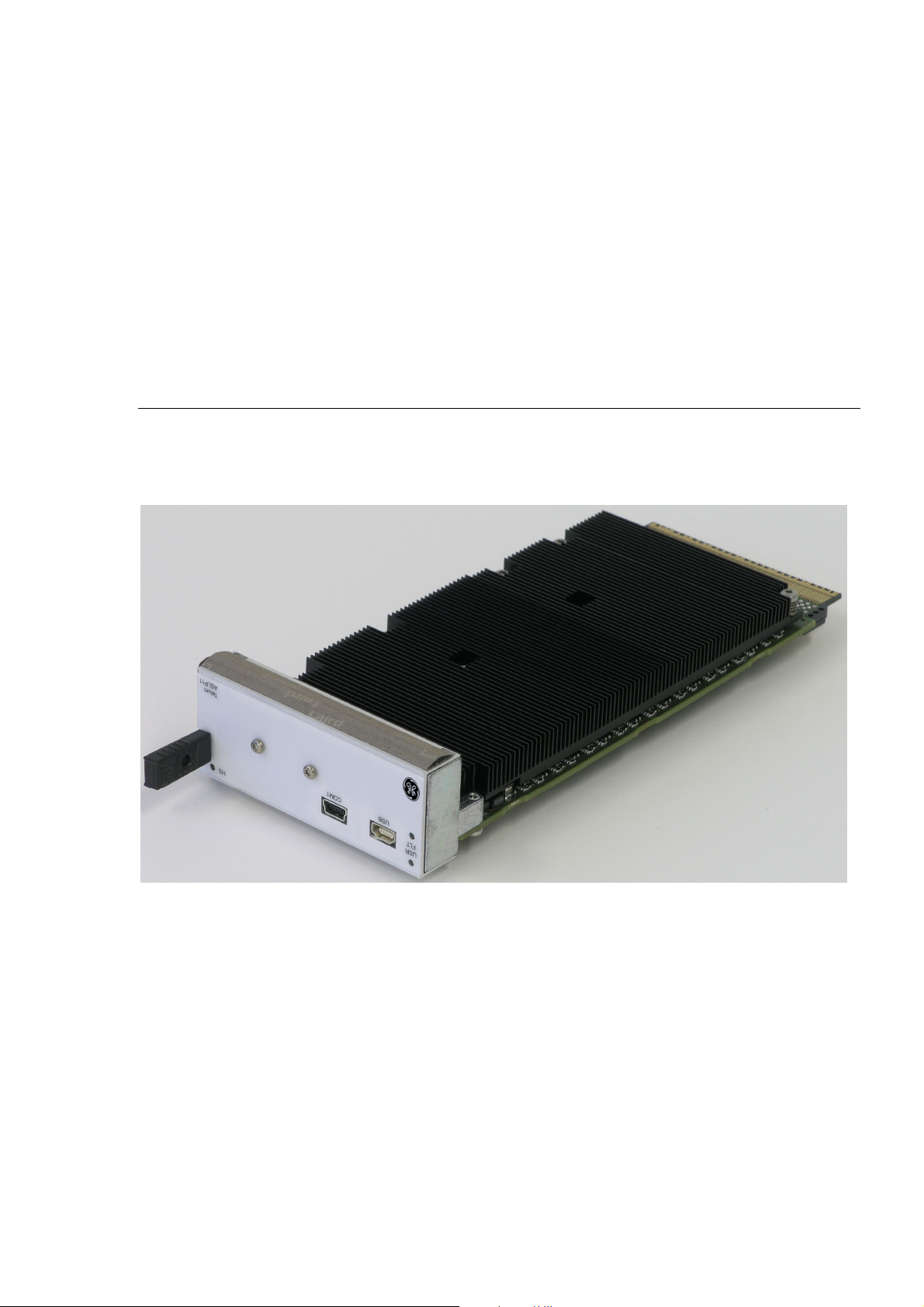
Figure 1: ASLP11 board
Chapter Scope
This chapter describes features, capabilities and compatibility of the ASLP11
AMC Single Board Computer.
Board Design
The ASLP11 is a fully IBM-AT compatible stand-alone PC. It is equipped with
many functions which a conventional Personal Computer can only offer with
several add-on cards. Extension boards can be connected via the AMC
interface. The minimized board size and the large number of interfaces and
GE Intelligent Platforms – ASLP11 Hardware Reference Manual, Third Edition Page 17
Page 18

functions allow the ASLP11 to be used in many applications. See the following
block diagram for the board design.
GE Intelligent Platforms – ASLP11 Hardware Reference Manual, Third Edition Page 18
Page 19
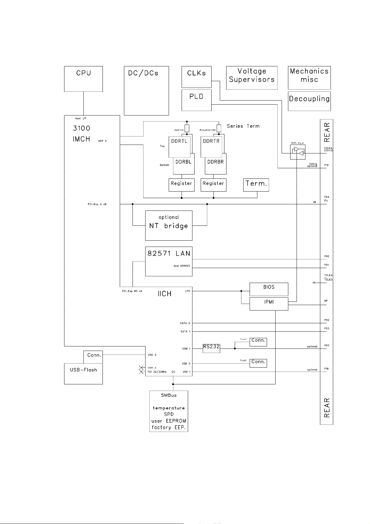
Figure 2: Block diagram
GE Intelligent Platforms – ASLP11 Hardware Reference Manual, Third Edition Page 19
Page 20

Design Features
The ASLP11 AMC Single Board Computer features:
Microprocessor
Intel® Core Duo processor and
Intel® Core 2 Duo processor 1.5 GHz
DRAM
512 MB to 4 GB DDRII 400MHz with ECC
Chipset
Intel 3100 single chip
Flash BIOS
Easy updating, in-system programmable
AMIBIOS
EEPROM (Serial)
64 KBytes for user information
CMOS RAM
114 byte non-volatile RAM for BIOS purposes
MC146818 compatible RTC without battery supply
USB
One front USB 2.0 port (and one rear on request)
Watchdog
Watchdog implemented in chipset
High Resolution Timer
System timer, allows “Real Time Functions” implemented in chipset
Ethernet
Two Gigabit high speed Ethernet channels with Intel 82571EB Ethernet
controller
SATA IDE
SATA 150 IDE/ATAPI interface with two IDE devices
Serial I/O
on front one asynchronous 16550 compatible channel with 16 byte FIFO,
Transfer rates up to 115.2 kBaud, (on request on rear too).
AMC Slot
ASLP11 works in an AMC Type B+ Slot with two Ethernet, two SATA and
one PCI-Express x8 link and Hot Swap functionality.
Works either as PCIe root complex or as PCIe endpoint.
On request one USB and one serial port
IPMI
Hitachi controller for support of Intelligent Peripheral Management Interface.
GE Intelligent Platforms – ASLP11 Hardware Reference Manual, Third Edition Page 20
Page 21

Temperature Sensor
Measures temperatures of CPU-die and onboard. The sensor is software
readable in 1°C increments from -55 to +125°C.
Front panel I/O
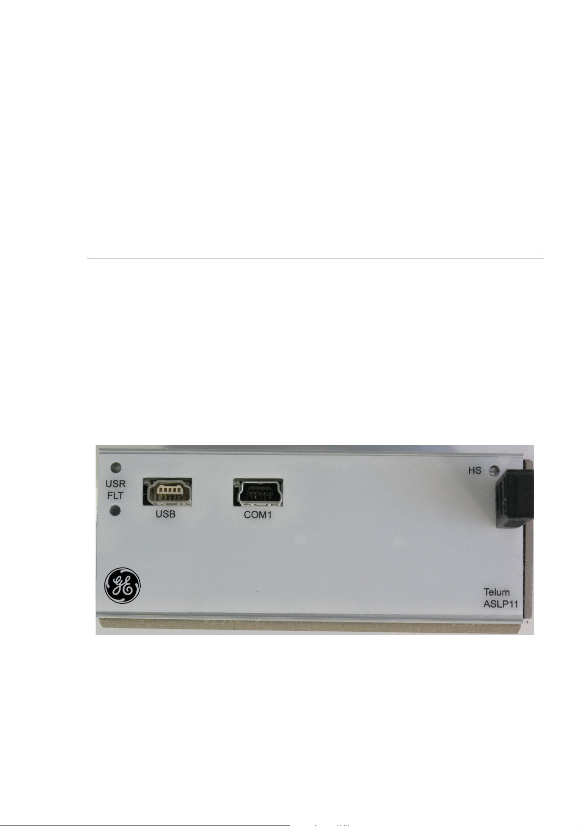
Mini USB-A for USB, mini USB-B for serial, 3xLED (blue: HotSwap; green,
bicolor: user definable or fault display)
Power supply Usage
+3.3 V for IPMI Management controller supply
+12 V for board supply
Approval
Designed to meet standard UL1950, CE class A, FCC-A
Styles available
ASLP11 is available in standard or extended temperature style.
GE Intelligent Platforms – ASLP11 Hardware Reference Manual, Third Edition Page 21
Page 22

Page 23

CHAPTER 2 Unpacking and Inspection
Chapter Scope
This chapter covers the suggested inspection and preparation considerations
and background information necessary prior to using the ASLP11. Unpacking,
initial inspection, and first-time operation of the ASLP11 are covered.
Following the procedures given in the chapter is recommended, since they will
verify proper operation after shipping and before the product is integrated into
your system.
ESD
Electrostatic Discharge Notice
The discharge of static electricity, known as Electro Static Discharge or ESD, is
a major cause of electronic component failure. The ASLP11 has been packed in
a static-safe bag which protects the board from ESD while the board is in the
bag. Before removing the ASLP11 or any other electronic product from its
static-safe bag, be prepared to handle it in a static-safe environment.
You should wear a properly functioning antistatic strap and ensure you are fully
grounded. Any surface upon which you place the unprotected ASLP11 should
be static-safe, usually facilitated by the use of antistatic mats. From the time the
board is removed from the antistatic bag until it is in the card cage and
functioning properly, extreme care should be taken to avoid “zapping” the
board with ESD. You should be aware that you could “zap” the board without
knowing it; a small discharge, imperceptible to the eye and touch, can often be
enough to damage electronic components. Extra caution should be taken in cold
and dry weather when static easily builds up.
GE Intelligent Platforms – ASLP11 Hardware Reference Manual, Third Edition Page 23
Page 24
Unpacking and Handling
Although the ASLP11 is carefully packaged to protect it against the rigors of
shipping, it is still possible that shipping damages can occur. Careful inspection
of the shipping carton should reveal some information about how the package
was handled by the shipping service. If evidence of damage or rough handling
is found, you should notify the shipping service and GE Intelligent Platforms as
soon as possible.
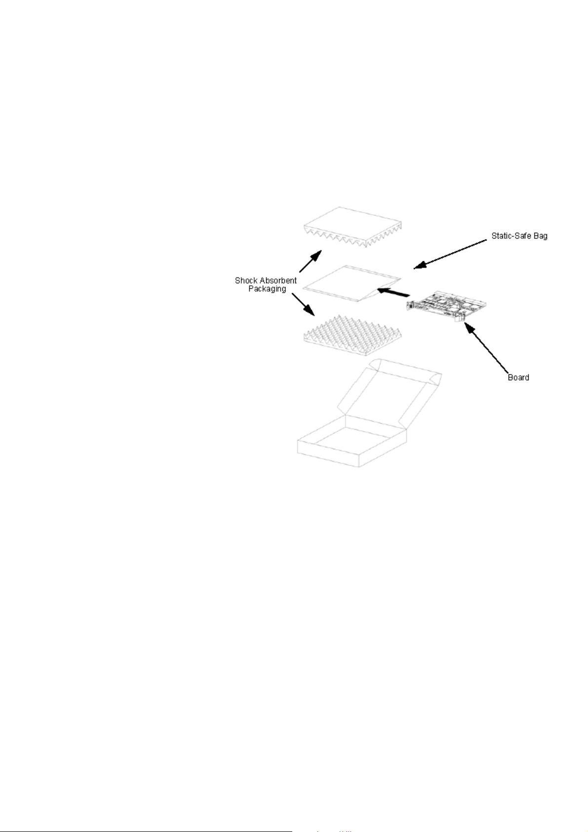
Sample packaging
Retain all packing material in case of future need.
Only after ensuring that both you and the surrounding area are protected from
ESD, carefully remove the ASLP11 from the shipping carton by grasping it by
the front panel. Place the board, in its antistatic bag, flat down on a suitable
surface. You may then remove the board from the antistatic bag by tearing the
ESD warning labels.
Proper handling of the ASLP11 is critical to ensure proper operation and longterm reliability. When unpacking the board, and whenever handling it
thereafter, be sure to hold the board by the front panel. Do not hold the board
by the circuit card edges, the heat sink, or the connectors.
GE Intelligent Platforms – ASLP11 Hardware Reference Manual, Third Edition Page 24
Page 25

Initial Inspection
After unpacking the ASLP11, you should inspect it for visible damage that
could have occurred during shipping or unpacking. If damage is observed
(usually in the form of bent component leads or loose socketed components),
contact GE Intelligent Platforms for additional instructions. Depending on the
severity of the damage, it may need to be returned to the factory for repair.
DO NOT apply power to the board if it has visible damage. Doing so may
cause further, possibly irreparable damage, as well as introduce a fire or shock
hazard.
Delivery Volume
Please check that the delivered package contains the following items:
Qty. Item Purpose
1 ASLP11 AMC Single Board Computer
Technical Product Information
1 CDROM
with driver software and manuals in Adobe Acrobat
(PDF) format
The manual files are also available through the World Wide Web from our
Web-Server:
http://www.ge-ip.com
Available Accessories
Please contact the sales department or your sales representative for latest
information on options and accessories.
Item Purpose
YLU015MB Adapter cable for connecting Standard size USB type A
cables and devices to the ASLP11 front panel mini USB
type A connector
YLU050MD
Adapter cable for connecting Standard DSUB9 RS232
cables to the ASLP11 front panel mini USB type B serial
connector
Accessories are subject to change without notice.
GE Intelligent Platforms – ASLP11 Hardware Reference Manual, Third Edition Page 25
Page 26

Page 27

CHAPTER 3 Installation
Chapter Scope
This chapter covers the installation of the ASLP11 AMC Single Board
Computer in an AMC carrier and initial power-on operations.
Advice
Please observe all safety procedures to avoid damaging system and protect
operators and users.
Unpacking and Handling
Please read the manual carefully before unpacking the module or fitting the
device into your system. Also adhere to the following:
• Observe all precautions for electrostatic sensitive modules
• If the product contains batteries, please do not place the board on
conductive surfaces, antistatic plastic, or sponge, which can cause shots
and lead to battery or board trace damage.
• Please do not exceed the specified operating temperatures. Note that
batteries and storage devices might also have temperature restrictions.
• Keep all original packaging material for future storage or warranty
shipments of the board.
ESD
Electrostatic Discharge (ESD) is a major cause of electronic component failure.
The ASLP11 has been packed in a static-safe bag which protects the board
from ESD while the board is in the bag. From the time the board is removed
from the antistatic bag until it is properly mounted in a carrier, extreme care
should be taken to avoid damaging board through electrostatic discharges. See
page 23 for details on how to prevent “zapping” the board with ESD.
GE Intelligent Platforms – ASLP11 Hardware Reference Manual, Third Edition Page 27
Page 28

General Advice
Before installing or removing any board, please ensure that the system power
and external supplies have been turned off.
Advice on AMC products
Mount the CPU board carefully on the AMC carrier slot.
Minimum System Requirements
As shipped, the ASLP11 has been thoroughly tested, and is nearly ready for use
in your system. In order to verify ASLP11 operation for the first time, it is
suggested that you configure a minimal system. It is not necessary to have disk
drives, a Flash disk or other accessories connected in order to perform the
ASLP11 confidence tests.
Because the ASLP11 is available in several options the description in this
chapter is related to the standard configuration.
The following items are required to start the ASLP11 in a standard
configuration:
Carrier and Power Supply
You will need a standard AMC carrier wired into a regulated power supply
capable of providing stable low noise +12 V source. Make sure that the supply
is capable of meeting the total power requirements of the ASLP11. Please refer
to chapter “Specifications” on page 53 for details.
The ASLP11 features Full Hot Swap capabilities. This allows orderly insertion
and extraction of the board from the system host without having to power down
the system. See chapter “Hot Swap” on page 49 for details.
Installation
After making sure that you have installed the ASLP11 properly into your AMC
carrier, apply power to it. When the board finished its reset sequence, the
processor should begin executing initial BIOS-resident routines.
Note: Make sure that the card ejector is closed and the Hot Swap LED (blue) is
OFF.
Please see chapter “Interfaces” for details on onboard interfaces. The location
of the ASLP11 interfaces is shown on page 35.
Initial Power-On Operation
After some seconds, the ASLP11 system BIOS comes up and the red LED on
the front will switch off and finally change to non-blinking green.
The board is running properly now and is ready to be installed and setup for
your application.
GE Intelligent Platforms – ASLP11 Hardware Reference Manual, Third Edition Page 28
Page 29

Entering the BIOS SETUP
Whenever you want to work manually at the ASLP11, you need some sort of
console connection. Either you use the optional serial port or the planned
console rerouting via Ethernet or you have to connect a graphics card to the
PCI-Express port.
To enter SETUP during the initial power-on sequence press the DELETE key
during the boot-up sequence. Check the on-screen messages. This tells you
when you can enter the BIOS by pressing the DELETE key. You may also
press the DELETE key when the LED changes from blinking amber to blinking
green.
Consult the 'AMIBIOS for ASLP11 User’s and Programmer’s Manual' for
further information on how to change settings and configurations.
If the board does not perform as described above, some damage may have
occurred in shipping or the board is not installed or set up properly. Contact GE
Intelligent Platforms technical support as described in chapter “Support,
Service, and Warranty Information” for further instructions.
If the current BIOS settings do not allow the system to boot, holding down the
“End” key while the USR1 is blinking amber will load the “Failsafe Defaults”
set.
The BIOS ID is shown on the bottom line of POST display.
Example/coding of the ID line:
62 – 0102 – 004199 – 00101111 – 071595 - E7501 – ASLP11– Y2KC-0
Year 2000 compliant
project ID
Chip set
AMIBIOS core copyright date
BIOS features
supplier ID
major & minor BIOS revisions
processor, flash ROM size
GE Intelligent Platforms – ASLP11 Hardware Reference Manual, Third Edition Page 29
Page 30

Page 31

CHAPTER 4 Getting Started
Chapter Scope
This chapter gives some useful tips when using a board from ASLP11 family
the first time. It might be also useful to read this chapter carefully, when
problems came up in using the ASLP11.
Power Supply
The ASLP11 board requires up to 70 Watts from the power supply. For exact
values please check the section specification or the actual datasheet, but for
rough data a current of up to 6A at the 12 V rail and 0.1 A at the 3.3 V
management power rail must be taken into consideration. If you ever see the
board not starting well or doing resets at random states, please check the
voltage of the supply voltages at the AMC slot. When measuring there, you can
use a standard digital multimeter and you have to attach it to the positions
where no high current is flowing.
The +12 V should reach their nominal value when measuring with a
multimeter. If the voltage is less than 10.8 V then short voltage drops while the
CPU or memory gets into high activities may result in resetting the ASLP11
board.
Status indicator, Postcode and Beeps
The ASLP11 family has 3 color LEDs at the front panel for a quick status
indicator usage. There is a blue Hot Swap LED (HS), a green Status LED (‘in
Service’) and a bicolor LED (when red used as ‘Fault’). Its possible colors are
red, orange or green and the LEDs can blink in different frequencies or be on
continuously.
The blue Hot Swap LED (HS) is required and used according to the AMC.0
specification.
GE Intelligent Platforms – ASLP11 Hardware Reference Manual, Third Edition Page 31
Page 32

Booting
On the rear side of the PCB there are several more LEDs showing the status of
various interfaces. They cannot be viewed from the front, but may be helpful
for debug purposes. There are the link/activity (green/amber) status of Ethernet
channel 0 (‘E0’) and Ethernet channel 1 (‘E1’), the PCIe host link towards the
PCIe switch (‘HL’, green x1 or x4, amber x8) and the PCIe link towards the
AMC interconnect (‘AL’, green x1 or x4, amber x8) and the BIOS controlled
status LED (‘ST’). This LED shows the same information than the bicolor front
panel LED, but isn’t controlled via IPMI when booting the operating system. It
also shows the short red blinks every second when the CPU gets too hot and the
internal throttle function has been activated. Whenever the ASLP11 does not
complete its BIOS bootup sequence, this LED also shows the postcode in
blinking it serialized.
The status LED for the PCIe host link ‘HL’ and PCIe AMC link ‘AL’ are not
mounted when the PCIe switch isn’t mounted via order.
When switching-on the ASLP11 the following steps are done by hardware:
- On the ASLP11 family, all voltages at the carrier are observed until they reach
a first trip point which is 2.9 V at the 12 V rail.
- The continuous red fault LED (FLT) shows that all circuitry is in reset
- All onboard DC/DC converters are ramped up
- If all onboard supply voltages are at their correct values, the powergood status
is acknowledged to all onboard devices and the red fault LED (FLT) is
switched off
- After this the CPU starts reading the first instructions from BIOS. Very soon
the bicolor LED (USR1) is programmed to a red blinking state and the first
postcode is issued
- If the CPU does not start correctly, the red fault LED (FLT) keeps off until the
hardware watchdog will issue a further reset around 1.6 seconds later. You can
see this at the red fault LED (FLT), which is on again for a short moment. This
sequence continues until the CPU starts correctly.
For reference the BIOS boot sequence is shown with the former BIOS version.
This version is a rather early one and hopefully some of the long periods will
speed up. The times depend mainly on the memory size and they are measured
with 1GB and quick boot enabled. All postcodes are shown in hex.
GE Intelligent Platforms – ASLP11 Hardware Reference Manual, Third Edition Page 32
Page 33

Table 1: Bootup timing
Setup
Hot Swap
Time after releasing
PCI reset
1 µs D0 Red 1Hz blinking
726 ms AC Orange 1Hz blinking All memory is initialized
3.9 s D4
8.4 s D6
12.2 s D7
12.3 s 03 Green 1 Hz blinking Keyboard enabled *1
12.7 s 4013 Green 2 Hz blinking
15.2 s 202A Video Bios is started
16.9 s 3C Green 3 Hz blinking
17.2 s 78 Starting external BIOS
17.2 s 8C Green 4 Hz blinking
17.3 s 00 Green steady on
POST
CODE
Status LED Comment
Try booting from mass
storage
*1 now is the right point to press DEL if you want to go to BIOS SETUP
Whenever you want to work manually at the ASLP11, you need some sort of
console connection. Either you use the optional serial port or the planned
console rerouting via Ethernet or you have to connect a graphics card to the
PCI-Express port.
If you want to enter the BIOS Setup, you have to press the keyboard ‘DEL’ key
at the right moment. Especially when using a slow starting monitor it might be
too late to wait for the CRT to show the message ‘Press DEL to enter Setup’.
Better look for the LED and press ‘DEL’ as soon as the LED changes from
orange to green blinking. When you are using add-on cards with external BIOS,
you can hit the DEL key while their BIOS runs (i.e. SCSI BIOS device scan).
When you miss the right moment to press the DEL key, please use the reset
button on the front panel to restart the power up sequence or switch off the
power supply for a few seconds and restart it. With the current BIOS pressing
the Ctrl-Alt-Del key combination at this boot-moment will result in switching
to the next bootable device and try to boot from this. This feature cannot be
disabled within Setup.
The ASLP11 family supports full hot swap according to AMC.0. This includes
all hardware functionality to detect other bus cards or devices to be plugged in
or removed while the system is running under power. Also the ASLP11 can be
hot-plugged to a running system or be removed from it.
The necessary software/driver and operating system handling is not done within
the BIOS of the ASLP11, because all the tasks to recognize new inserted
boards, to re-enumerate the PCI memory space while other cards/transfers are
GE Intelligent Platforms – ASLP11 Hardware Reference Manual, Third Edition Page 33
Page 34

Unexpected Resets
still running, cannot be done within the BIOS. These tasks have to be fully
done by the used operating system. Currently GE Intelligent Platforms have no
drivers to support these functionalities.
The handling of the blue LED is also done within the necessary drivers. So do
not expect the blue LED to go on and off according to the AMC specification if
no driver is loaded.
Whenever the ASLP11 unexpectedly issues a reset and starts booting again,
you may want to know the reset source. For this reason a set of special registers
is implemented onboard. Each reset source is indicated by a certain bit and can
be read during the next boot-up. The register description can be found in the
‘Board Specific Hardware Programmer’s Manual’.
GE Intelligent Platforms – ASLP11 Hardware Reference Manual, Third Edition Page 34
Page 35
CHAPTER 5 Interfaces
Chapter Scope
This chapter describes the interfaces of the ASLP11 AMC Single Board
Computer located on the board and on the front panel. Each section includes a
pin assignment table as well as notes on certain signal line characteristics, if
necessary.
Front Panel Interfaces
Refer to the next drawing for the location of interfaces on the front panel of the
ASLP11 board:
GE Intelligent Platforms – ASLP11 Hardware Reference Manual, Third Edition Page 35
Page 36

ASLP11 Connectors
This chapter describes connector pin assignments on the ASLP11.
AMC Connector Port Mapping
This Table describes the port mapping according to the AMC spec.
Table 2: AMC port mapping
Port # ASLP11 Function AMC spec.
Port 0 Gigabit Ethernet 0 AMC.2 E2
Port 1 Gigabit Ethernet 1 AMC.2 E2
Port 2 SATA 0 AMC.3 S2
Port 3 SATA 1 AMC.3 S2
Port 4 PCI Express 0 AMC.1 Type 8
Port 5 PCI Express 1 AMC.1 Type 8
Port 6 PCI Express 2 AMC.1 Type 8
Port 7 PCI Express 3 AMC.1 Type 8
Port 8 PCI Express 4 AMC.1 Type 8
Port 9 PCI Express 5 AMC.1 Type 8
Port 10 PCI Express 6 AMC.1 Type 8
Port 11 PCI Express 7 AMC.1 Type 8
Port 12 Not connected
Port 13 Not connected
Port 14 Not connected
Port 15 Not connected
Port 16 used as TCLKC, TCLKD within the
AMC spec.
Port 17 Not connected
Port 18 Not connected (opt. USB) (*)
Port 19 Not connected (opt. Debug) (default disabled)
Port 20 Not connected (opt. Serial) (default disabled)
FCLKA Input for PCIe 100MHz clock
Optional 100MHz clock output for
uTCA applications
TCLKA Not connected
TCLKB Not connected
TCLKC Not connected
TCLKD Not connected
* violates AMC.0 if optionally mounted, because there is no Tx/Rx separation
within the USB. The voltage level is according to AMC.0.
GE Intelligent Platforms – ASLP11 Hardware Reference Manual, Third Edition Page 36
Page 37

AMC Connector J9000
This interface is used for connection to a standard AMC carrier.
Table 3: Connector J9000 pin assignments
1 GND Logic Ground 170 GND Logic Ground
2 PWR Payload Power 169 TDI JTAG Test Data Input
3 PS1# Last Presence 1 168 TDO JTAG Test Data Output
4 MP Management Power 167 TRST# JTAG Test Reset Input
5 GA0 Geographic Address 0 166 TMS JTAG Test Mode Select In
6 RSRVD not assigned 165 TCK JTAG Test Clock Input
7 GND Logic Ground 164 GND Logic Ground
8 RSRVD not assigned 163 Tx20+ Not connected *
9 PWR Payload Power 162 Tx20- Not connected *
10 GND Logic Ground 161 GND Logic Ground
11 Tx0+ Eth 1 Transmitter + 160 Rx20+ Not connected *
12 Tx0- Eth 1 Transmitter - 159 Rx20- Not connected *
13 GND Logic Ground 158 GND Logic Ground
14 Rx0+ Eth 1 Receiver + 157 Tx19+ Not connected *
15 Rx0- Eth 1 Receiver - 156 Tx19- Not connected *
16 GND Logic Ground 155 GND Logic Ground
17 GA1 Geographic Address 1 154 Rx19+ Not connected *
18 PWR Payload Power 153 Rx19- Not connected *
19 GND Logic Ground 152 GND Logic Ground
20 Tx1+ Eth 2 Transmitter + 151 Tx18+ Not connected *
21 Tx1- Eth 2 Transmitter - 150 Tx18- Not connected *
22 GND Logic Ground 149 GND Logic Ground
23 Rx1+ Eth 2 Receiver + 148 Rx18+ Not connected
24 Rx1- Eth 2 Receiver - 147 Rx18- Not connected
25 GND Logic Ground 146 GND Logic Ground
26 GA2 Geographic Address 2 145 Tx17+ Not connected
27 PWR Payload Power 144 Tx17- Not connected
28 GND Logic Ground 143 GND Logic Ground
29 Tx2+ SATA 0 Transmitter + 142 Rx17+ Not connected
30 Tx2- SATA 0 Transmitter - 141 Rx17- Not connected
31 GND Logic Ground 140 GND Logic Ground
32 Rx2+ SATA 0 Receiver + 139 TCLKD+ Not connected
33 Rx2- SATA 0 Receiver - 138 TCLKD- Not connected
34 GND Logic Ground 137 GND Logic Ground
35 Tx3+ SATA 1 Transmitter + 136 TCLKC+ Not connected
36 Tx3- SATA 1 Transmitter - 135 TCLKC- Not connected
37 GND Logic Ground 134 GND Logic Ground
38 Rx3+ SATA 1 Receiver + 133 Tx15+ Not connected
39 Rx3- SATA 1 Receiver - 132 Tx15- Not connected
GE Intelligent Platforms – ASLP11 Hardware Reference Manual, Third Edition Page 37
Page 38

40 GND Logic Ground 131 GND Logic Ground
41 EN# Enable 130 Rx15+ Not connected
42 PWR Payload Power 129 Rx15- Not connected
43 GND Logic Ground 128 GND Logic Ground
44 Tx4+ PCI Exp 0 Transmitter + 127 Tx14+ Not connected
45 Tx4- PCI Exp 0 Transmitter - 126 Tx14- Not connected
46 GND Logic Ground 125 GND Logic Ground
47 Rx4+ PCI Exp 0 Receiver + 124 Rx14+ Not connected
48 Rx4- PCI Exp 0 Receiver - 123 Rx14- Not connected
49 GND Logic Ground 122 GND Logic Ground
50 Tx5+ PCI Exp 1 Transmitter + 121 Tx13+ Not connected
51 Tx5- PCI Exp 1 Transmitter - 120 Tx13- Not connected
52 GND Logic Ground 119 GND Logic Ground
53 Rx5+ PCI Exp 1 Receiver + 118 Rx13+ Not connected
54 Rx5- PCI Exp 1 Receiver - 117 Rx13- Not connected
55 GND Logic Ground 116 GND Logic Ground
56 SCL IPMB-L Clock 115 Tx12+ Not connected
57 PWR Payload Power 114 Tx12- Not connected
58 GND Logic Ground 113 GND Logic Ground
59 Tx6+ PCI Exp 2 Transmitter + 112 Rx12+ Not connected
60 Tx6- PCI Exp 2 Transmitter - 111 Rx12- Not connected
61 GND Logic Ground 110 GND Logic Ground
62 Rx6+ PCI Exp 2 Receiver + 109 Tx11+ PCI Exp 7 Transmitter +
63 Rx6- PCI Exp 2 Receiver - 108 Tx11- PCI Exp 7 Transmitter –
64 GND Logic Ground 107 GND Logic Ground
65 Tx7+ PCI Exp 3 Transmitter + 106 Rx11+ PCI Exp 7 Receiver +
66 Tx7- PCI Exp 3 Transmitter - 105 Rx11- PCI Exp 7 Receiver –
67 GND Logic Ground 104 GND Logic Ground
68 Rx7+ PCI Exp 3 Receiver + 103 Tx10+ PCI Exp 6 Transmitter +
69 Rx7- PCI Exp 3 Receiver - 102 Tx10- PCI Exp 6 Transmitter –
70 GND Logic Ground 101 GND Logic Ground
71 SDA IPMB-L Data 100 Rx10+ PCI Exp 6 Receiver +
72 PWR Payload Power 99 Rx10- PCI Exp 6 Receiver –
73 GND Logic Ground 98 GND Logic Ground
74 TCLKA+ Not connected 97 Tx9+ PCI Exp 5 Transmitter +
75 TCLKA- Not connected 96 Tx9- PCI Exp 5 Transmitter –
76 GND Logic Ground 95 GND Logic Ground
77 TCLKB+ Not connected 94 Rx9+ PCI Exp 5 Receiver +
78 TCLKB- Not connected 93 Rx9- PCI Exp 5 Receiver –
79 GND Logic Ground 92 GND Logic Ground
80 FCLKA+ PCI Exp Clock+ 91 Tx8+ PCI Exp 4 Transmitter +
81 FCLKA- PCI Exp Clock- 90 Tx8- PCI Exp 4 Transmitter –
GE Intelligent Platforms – ASLP11 Hardware Reference Manual, Third Edition Page 38
Page 39

82 GND Logic Ground 89 GND Logic Ground
83 PS0# Last Presence 0 88 Rx8+ PCI Exp 4 Receiver +
84 PWR Payload Power 87 Rx8- PCI Exp 4 Receiver –
* these pins are normally not connected, but do have an optional usage for
following functions:
Table 4: J9000 additional functions
150 Tx18- USB rear -
151 Tx18+ USB rear +
153 Rx19- Debug function 1 (not defined)
154 Rx19+ Debug function 2 (Speaker Data Out)
156 Tx19- Debug function 3 (POST CLK)
157 Tx19+ Debug function 4 (POST Data)
159 Rx20- COM1 CTS
160 Rx20+ COM1 RXD
162 Tx20- COM1 RTS
163 Tx20+ COM1 TXD
USB Interfaces P1680
One USB channel is available at the front panel. It is a mini USB-A type. For
connection of standard size USB-A connectors please use the suitable adaptor
cable YLU015MB from GE Intelligent Platforms.
Table 5: USB connector P1680 pin assignments
Name P1680
+5 V 1
USB- 2
USB+ 3
n.c. 4
GND 5
Connectors P1680 provide VCC voltage (+5 V). The total current drawn from
this source must not exceed 0.5 A otherwise the board will do a power on reset.
This may also happen when inserting an USB device which incorporates some
larger capacitor to the supply voltage (i.e. some USB hubs). It is not an ESD
issue, but only related to the short current pulse, which is limited to uncritical
values.
Serial Interfaces P1682
One RS232 serial channel is available at the front panel. It is a mini USB-B
type connector. For connection of standard female DSUB9 connectors please
use the suitable adaptor cable YLU050MD from GE Intelligent Platforms.
GE Intelligent Platforms – ASLP11 Hardware Reference Manual, Third Edition Page 39
Page 40

Table 6: Serial interface P1682 pin assignments
Name P1682 DSUB 9 male
TxD 1 3
RxD 2 2
CTS 3 4,8
RTS 4 (7) *
GND 5 5
* This pin is not connected within the adapter cable YLU050MD. Therefore
only a TxD/RxD handshaked (with CTS) connection is possible. Users needing
a full TxD/RxD and RTS/CTS handshake must build there own adapter cable.
GE Intelligent Platforms – ASLP11 Hardware Reference Manual, Third Edition Page 40
Page 41

CHAPTER 6 Resources
Chapter Scope
This chapter describes system resources, such as memory mapping, register
set and default interrupt request assignments.
Memory Map
The table below shows the memory address area used by the ASLP11.
Register Set
Table 7: Memory Map
Address Size Used by
$00000 - $9FFFF 640 kBytes System RAM
$A0000 - $BFFFF 128 kBytes Video RAM (if enabled)
$C0000 - $DFFFF 128 kBytes
$E0000 - $FFFFF 128 kBytes System BIOS
$100000 - $3FFFFFFF Depends on DRAM Extended RAM
$4000000 - $FFF7FFFF Depends on DRAM
$FFF80000 - $FFFFFFFF 512 kBytes System BIOS
The following section provides an overview of the registers located in the I/O
address space of the ASLP11.
Note:
The address location of PCI devices such as SCSI or Ethernet are not
described in the following tables because the System BIOS automatically
configures (PnP, Plug and Play) each PCI device to avoid address conflicts.
Many device drivers show the actual address locations after installation and
loading.
Used by various PCI ROMs
such as VGA, SCSI, Ethernet
Dynamically used by PCI
devices
GE Intelligent Platforms – ASLP11 Hardware Reference Manual, Third Edition Page 41
Page 42

Standard Register Set
The standard register set is the same as with standard PC/AT systems. The
table below provides an overview of the address ranges occupied by these
registers.
Table 8: Standard register set
I/O Address Range (Hex) Function
0000 - 000F DMA Controller 1
0020 - 0021 Interrupt Controller 1
0040 - 0043 Counter / Timer
0060 Keyboard Controller
0061 NMI Status and Control
0064 Keyboard Controller
0070 - 0071 RTC, NMI Mask
0080 - 008F DMA Page register
00A0 - 00A1 Interrupt Controller 2
00B2 - 00B3 Power Management
00C0 - 00DE DMA Controller 2
Interrupts
00F0 - 00F1 Coprocessor
0160 - 016F Reserved
a
0170 - 0177 Secondary IDE
01F0 - 01F7 Primary IDE
a. Used for onboard programmable options. They are not intended to be
used from normal users. For more explanation please check the ‘Board
Specific Hardware Programmer’s Manual’
Plug and Play Devices
See “Board Specific Hardware Programmer’s Manual”
The interrupt routing for standard components such as COM1/2 or LPT1 is in
compliance with standard PC/AT systems. Unused interrupts can be used for
add-on cards or other board specific PCI devices such as SCSI and Ethernet.
GE Intelligent Platforms – ASLP11 Hardware Reference Manual, Third Edition Page 42
Page 43

APIC Controller
Table 9: Interrupts
Hardware IRQ IRQ Source
INTC1
IRQ00 System Timer
IRQ01 Keyboard
IRQ02 Cascade from INTC2
a
IRQ03 COM2 / COM1
IRQ04 COM1 / COM2
a
IRQ05
IRQ06
IRQ07
INTC2
IRQ08 Real Time Clock
b
IRQ09 Power Management Contr./PCI
b
IRQ10 PnP/PCI
IRQ11 PnP/PCI
IRQ12 PS/2 Mouse
b
c
IRQ13 Numeric Coprocessor
IRQ14 SATA
IRQ15
Parity Error,
NMI
ECC Error,
System Error
a
. This interrupt is available when no Interrupt Service Routine is installed.
b
. Interrupts are available for Plug and Play PCI devices
c
. This interrupt is available when PS/2 mouse is not connected.
d
. This interrupt is available when the primary IDE is disabled in SETUP.
e
. This interrupt is available when the secondary IDE is disabled in SETUP.
The ASLP11 supports also the Interrupt handlings with APIC (Advanced
Interrupt Controller). This handling of the APIC interrupt services must be
supported by the operating system. The I/O APIC handles interrupts very
differently than the 8259. Briefly, these differences are:
• Method of Interrupt Transmission. The I/O APIC transmits interrupts
through a three wire bus, and interrupts are handled without the need for the
processor to run an interrupt acknowledge cycle.
• Interrupt Priority. The priority of interrupts in the I/O APIC is
independent of the interrupt number. For example, interrupt 10 may be given
a higher priority than interrupt 3.
• More Interrupts. The I/O APIC in the Intel 3100 supports a total of 24
interrupts.
GE Intelligent Platforms – ASLP11 Hardware Reference Manual, Third Edition Page 43
Page 44

For complete operation description please refer to the “Intel 3100 Controller”
datasheet.
GE Intelligent Platforms – ASLP11 Hardware Reference Manual, Third Edition Page 44
Page 45

CHAPTER 7 Function Blocks
Chapter Scope
This section gives a brief overview of the software interfaces of onboard
devices on the ASLP11 AMC Single Board Computer.
Processor
The Intel Pentium M processor family provides high performance with low
power and features Enhanced Intel SpeedStep® technology which provides
the ability to dynamically adjust the power and performance of the processor
based on CPU demand. This results in optimal performance without
compromising the power performance of the ASLP11.
The processor die is thermally protected by two thermal monitor features.
When reaching a maximum safe operating temperature the Thermal Control
Circuit in the processor activates a throttling feature and reduces the voltage
and frequency dynamically. If this feature is active the ASLP11 will indicate
it with short blinks at the red LED. In case of a catastrophic die overheating
(above 125°C) the ASLP11 switches off the processor core voltage. Recovery
from this catastrophic event can be done with a power off-on cycle only.
Memory Controller
The memory controller in the ASLP11 3100 chipset from Intel supports
double data rate ‘2’ synchronous DRAM (DDR II SDRAM) with a data bus
width of 64 bits + ECC. One or two banks are provided by the ASLP11 with
a size of either 512 Mbytes up to 2 GBytes. This results in a minimum
memory size of 512 Mbytes and a maximum total size of 4 Gbytes.
PCI-Express
The devices onboard and to the AMC connect are based on PCI express
(PCIe). The ASLP11 chipset works as a PCIe root complex (‘Master’) and
has an onboard PCIe switch PEX8518 from PLX towards the AMC connect.
This PCIe switch gives the possibility to work as an end point device
GE Intelligent Platforms – ASLP11 Hardware Reference Manual, Third Edition Page 45
Page 46

Interrupt Controller
Timer
(‘slave’). The decision in which mode the ASLP11 has to work, is done
within the IPMI handling before the payload power has been switched on.
Based on this PCIe switch two or more ASLP11 can be put into the same
system using a PCIe interconnect between them. When using the full link
width of 8 lanes (‘x8’), which must be supported by the used backplane, the
theoretical maximum transfer rate between any two of these ASLP11s is 4
GBytes/s.
The Interrupt controller on a standard PC consists of two 82C59A devices
with eight interrupt request lines each. The two controllers are cascaded so
that 14 external and two internal interrupt sources are available. The master
interrupt controller provides IRQ [7...1], the slave interrupt controller
provides IRQ [15...8]. IRQ2 is used to cascade the two controllers, IRQ0 is
used as a system timer interrupt and is tied to interval timer 1, counter 0. The
remaining 14 interrupt lines are mapped to various onboard devices. Each
82C59A provides several internal registers. The interrupts at the IRQ input
lines are handled by two registers, the interrupt request register IRR and the
in-service register ISR. For programming details see the 82C59A data sheet.
The ASLP11 supports also the Interrupt handlings with APIC (Advanced
Interrupt Controller). This handling of the APIC interrupt services must be
supported by the operating system. The I/O APIC handles interrupts very
differently from the 8259.
Standard PCs like the ASLP11 are equipped with an 8254 compatible timer.
This timer contains three counters. Each counter output provides a key system
function. Counter 0 is connected to interrupt controller input IRQ0 and
provides a system timer interrupt for time-of-day, floppy disk timeout and
other system timing functions. Counter 1 generates a refresh request signal
and Counter 2 generates the sound for the speaker.
The following table gives an overview over the 8254 functions.
GE Intelligent Platforms – ASLP11 Hardware Reference Manual, Third Edition Page 46
Page 47

Real Time Clock
EIDE Interface
USB Interface
Table 10: Interval timer functions
Interval Timer Functions
Function Counter 0 (System Timer)
Gate Always on
Clock In 1.193 MHz (OSC/12)
Out IRQ0 (INT1)
Function Counter 1 (Refresh Request)
Gate Always on
Clock In 1.193 MHz (OSC/12)
Out Refresh Request
Function Counter 2 (Speaker Tone)
Gate Programmable via Port $061
Clock In 1.193 MHz (OSC/12)
Out Speaker
The counter/timers are programmed by I/O accesses. A single control word
register controls the operation of all three counters. For more information on
programming and a detailed register description see the 8254 data sheet.
The RTC is a low-power clock that provides a time-of day clock and a 100year calendar with alarm features, but no battery backed operation. The timeof-day function includes 14 control registers. Other features include maskable
interrupt sources and 242 bytes of general purpose CMOS RAM used by
system BIOS. Valid RAM data and time can be maintained after power down
through the use of an external battery source. The RTC is software
compatible to the Dallas DS1287 and the Motorola MC146818.
The ASLP11 offers an EIDE/ATAPI interface with two SATA channels. This
device is logically connected to the primary PCI bus. The signals of the
SATA interfaces are available at the rear connector The ASLP11 System
BIOS automatically detects a connected HDD or CD-ROM and enters the
corresponding drive parameters into the BIOS setup. This feature allows
faster and easier handling of varying types of EIDE hard disks.
The ASLP11 has some USB 2.0 channels. These are backward compatible to
USB 1.0/1.1. The USB host controller supports legacy Keyboard/Mouse
usage with USB–based keyboard and mouse without using additional
software drivers.
GE Intelligent Platforms – ASLP11 Hardware Reference Manual, Third Edition Page 47
Page 48

IPMI
Ethernet Interface
A Baseboard management controller (BMC) is implemented on the ASLP11,
interfacing between host processor and the system management network. The
BMC maps its host interface (HIF) into the local CPUs I/O address space,
specified in the ‘ASLP11 Board Specific Hardware Programmer’s Manual’.
The functionality of the IPM controller and how to communicate with it
through the HIF is described in the ‘Intelligent Platform Management Interface
for ASLP11 User’s Manual’.
For information about the System Management in AMC systems, please refer
to the AMC System Management specification. More information about IPMI
can be found on the Intel website.
IPMB
The Intelligent Platform Management Bus (IPMB) is an I
2
C-based bus that
provides a standardized interconnection between different AMC-boards
within a chassis.
Private I
The Private IPMI I
'Additional devices/SMB'). The IPMI-controller works as a second Master on
the I
2
C
2
C bus to read the SMBus devices.
2
C bus is equivalent to the onboard SMBus (described in
Software Installation
The Technical Product Information CD-ROM supplied with the ASLP11
includes the most commonly used software drivers and utilities.
The Ethernet controller 82571 from Intel used with the ASLP11 is a high
performance dual Gigabit Ethernet PCI-Express controller. Both channels are
available on the ASLP11 rear connector according to the AMC specification.
For registration and identification of a workstation in a LAN, a unique ID
number is required. Each network card is assigned a unique ID number,
which resides in an Ethernet address ROM on the ASLP11. An Ethernet boot
option can be enabled in BIOS setup.
Software Installation
The drivers available for the Ethernet controller support a large number of
operating systems. The table shows operating systems supported by the
available software:
Table 11: Operating systems
Type System
ODI DOS
NDIS DOS
NDIS Windows 2000, XP
LINUX
GE Intelligent Platforms – ASLP11 Hardware Reference Manual, Third Edition Page 48
Page 49

Additional devices
The Technical Product Information CD-ROM supplied with the ASLP11
includes the most commonly used software drivers and utilities.
Hot Swap
The Hot Swap compliant ASLP11 allows the orderly insertion and extraction
under power, without adversely affecting system operation. The Hot Swap
process can be described in terms of three processes:
Physical Connection Process - describes the acts of:
• Hot Insertion - by which ASLP11 is installed into a live system
• Hot Extraction – which means the ASLP11 is removed from a live
system
• Hardware Connection Process - Power Up/Down of the ASLP11 onboard
voltages
• Software Connection Process - Connection/disconnection of the software
layer(s)
At the end of the Physical Connection Process (the shortest Pin has
connection) the Hot Swap controller powers up the onboard voltages in a
defined manner.
After the handle switches are closed, the AMC bridge generates an insertion
event, which signals a Hot Swap insertion to the system. The system then
scans the AMC-bus for changes.
Please note, that the AMC carrier must support this function and appropriate
software must be installed for Hot Swap to work properly.
SMBus devices
The ASLP11 uses a serial 2-wire I
2
C bus to communicate with several
onboard devices:
Table 12: SMBus devices
Device Designators SMBus address a
Clock synthesizer * U1000 1101 001Xb
Clock Buffer * U1110 1101 110Xb
Big User EEprom U1983 1010 010Xb
SPD EEprom Bank 0 * U1981 1010 100Xb
SPD EEprom Bank 1 * U1981 1010 101Xb
Factory EEprom * U1984 1010 11XXb
Temperature sensor LM83 U1982 0011 001Xb
IPMI Controller * U8000 0010 000Xb
Northbridge 3100 (slave) * U1300 0011 000Xb
Southbridge 3100 (slave) * U1300 1000 100Xb
Devices marked by * are handled by BIOS. It is strongly recommended not to
access these devices by user software.
An X at bit 0 represents the R/#W bit.
GE Intelligent Platforms – ASLP11 Hardware Reference Manual, Third Edition Page 49
Page 50

IPMB (external I²C)
The Intelligent Platform Management Bus (IPMB) is available on the AMC
connector to communicate with the IPM controller from afar. External access
via IPMB to the onboard SMBus devices can only be done via the IPMI
controller. For more information please see the IPMB description on page 48
within the IPMI controller section.
Temperature Sensor LM83
A National Semiconductor LM83 temperature sensor is implemented on the
ASLP11 board. The sensor is located close to the CPU and shows the dietemperature of the CPU and the local onboard temperature. The sensor has an
over-temperature output integrated, which can be used to take actions like
reducing the CPU speed. For programming information please see the
'AMIBIOS for ASLP11 User’s and Programmer’s Manual'.
More information on the LM83 can be found in the data sheet from National
Semiconductors.
Serial EEPROM
For storage of user data a serial EEPROM is implemented on the ASLP11
board. The user EEPROM is a 24C512 type with 64 kByte.
Reading and writing the user EEPROM is supported by software libraries
available for various operating systems.
Geographic Addressing
If the carrier supports geographic Addressing, the ASLP11 can detect the
unique Address in an AMC-System with the GA [2...0] Pins on the rear
connector.
For programming information please see the 'AMIBIOS for ASLP11 User’s
and Programmer’s Manual'. For more information about geographic
addressing in appliance to system management, see the AMC specification.
Watchdog
For security of application software, the ASLP11 offers a software controlled
hardware two stage watchdog with independent count values for each stage.
The first stage generates an INT or SMI. The second stage issuing a reset
signal if its time-out interval expires. The configurable granularity reaches
from 1µs to 10min.
For more information please see the Intel 3100 Controller datasheet and the
‘Board Specific Hardware Programmer’s Manual’.
LEDs
Three LEDs are available at the front panel bicolor (’FLT’), green (’in
Service’) and blue (HS).
GE Intelligent Platforms – ASLP11 Hardware Reference Manual, Third Edition Page 50
Page 51

The Status LEDs are used for BIOS power-up status indication, after boot
loading the IPMI control software is free to use this LED for its own purpose.
Table 13: BIOS Power-up status
Status USR1 LED color
Power-up, still Reset state Red on (also the blue LED is on)
BIOS early init Blink red 1 Hz
BIOS start POST Blink amber 1 Hz
BIOS POST init Blink green 1 Hz
OS boot Green on
System halted or reset Red on
The blue LED is the Hot Swap LED and is working according to the Hot
Swap specification.
JTAG
The ASLP11 supports the JTAG test interface according to the AMC.0
specification. For more information about the physical connections within the
queue please contact GE Intelligent Platforms.
GE Intelligent Platforms – ASLP11 Hardware Reference Manual, Third Edition Page 51
Page 52

GE Intelligent Platforms – ASLP11 Hardware Reference Manual, Third Edition Page 52
Page 53

CHAPTER 8 Specifications
PCB
FR4 Multilayer
Size
Single width, full height Type B+
Dimensions
PCB: 180.6 mm x 73.5 mm x 28.95 mm
Weight
Max. 350g
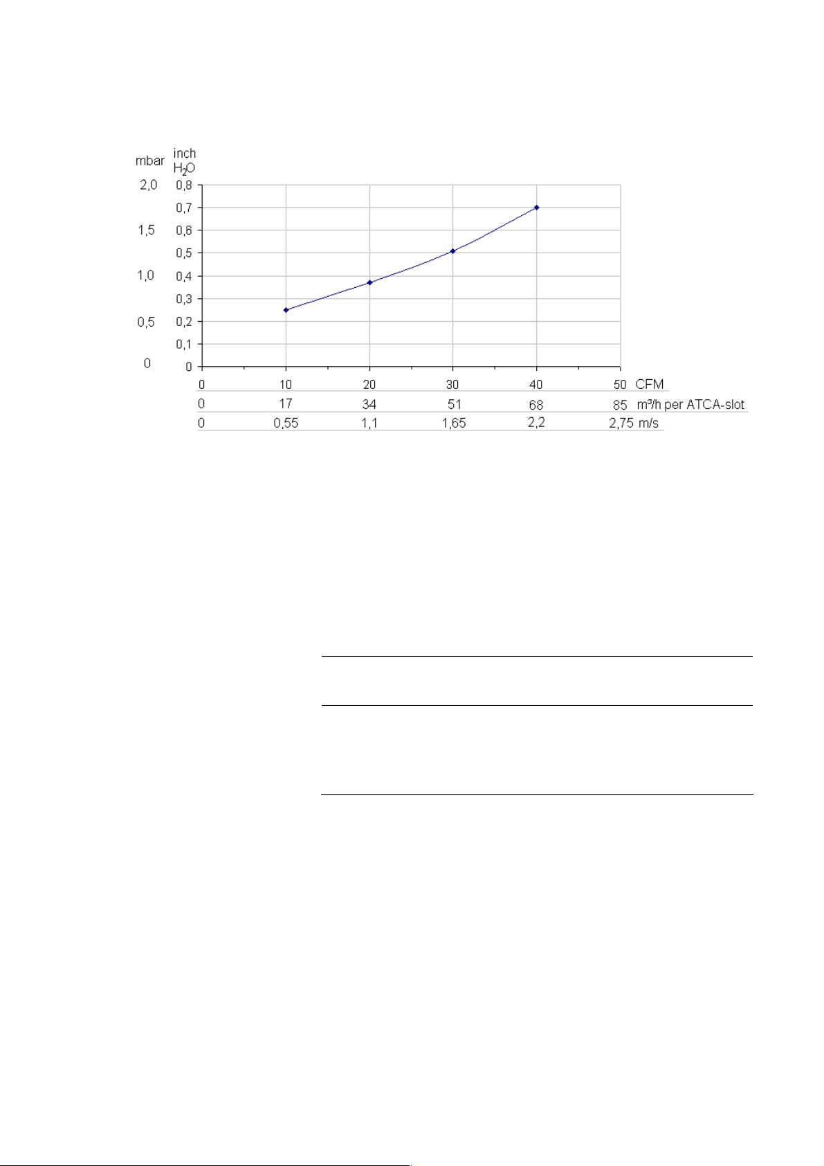
Pressure Loss
For your reference please find below a sketch showing the air pressure loss
when using the ASLP11 on an ATCA carrier. The values are estimated only
and will be updated as soon as measured data is available.
The pressure loss is shown in inch water and in mbar. The airflow is shown
on a volume basis in either CFM (cubic feet per minute) or m³/h (cubic meter
per hour) per ATCA slot. Alternatively you can find the linear air speed
shown in m/s (meter per second).
GE Intelligent Platforms – ASLP11 Hardware Reference Manual, Third Edition Page 53
Page 54
Power Consumption
• All commas are the international symbol for the decimal point.
• Please remark, that the air temperature increase per slot will be
higher than 2.5 K when using airflows less than 50 CFM or 2.75 m/s
under high power consumption conditions.
The following table is intended to help you calculate the power consumption
of an ASLP11 system. For measurement, the ASLP11 board is mounted on an
AMC carrier.
Table 14: ASLP11 typical Power consumption (+12.0 V)
Idle, CPU
CPU, DRAM, PCIe switch
1.5 GHz, 512 MB, no PCIe
switch
1.5 GHz, 2 GB, PCIe switch 35 W 45 W 51 W
2.16 GHz, 2 GB, PCIe
switch
cores at
90 °C
32 W 39 W 45 W
35 W 60 W 75 W
one core running
TDP at 100 °C
both cores running
TDP at 100 °C
• When the operating system brought the board into power down state S5,
the CPU supply is switched off and the total power consumption is
around 8W
• The idle power consumption values are shown using an operating system
which can handle the CPU speed step feature via ACPI
• The onboard IPMI controller consumes less than 0.1 A from the 3.3 V
management power supply.
• Connectors P1680 provide VCC voltage (+5 V). The total current drawn
from this source must not exceed 0.5 A.
GE Intelligent Platforms – ASLP11 Hardware Reference Manual, Third Edition Page 54
Page 55

No Battery Usage
The ASLP11 has no support for a battery to keep the date and time
information. The setup information is stored automatically within an onboard
EEPROM and is updated via standard BIOS Setup function. No external
software is needed to create a user defined setup like in earlier products from
GE Intelligent Platforms.
Environmental conditions
Ambient temperatures and humidity values for the ASLP11:
Table 15: Environmental values
C -Style I-Style
High Temperature
- Storage
- Operating (see diagram below)
Low Temperature
- Storage
- Operating
Temperature Shock
- Storage
- Operating
Relative Humidity
- Storage, Operating
+85 °C
-40 °C
0 °C
+/-10 °C/min
+/-5 °C/min
Up to 95 %, non-condensing
+85 °C
-40 °C
-40 °C
+/-20 °C/min
+/-10 °C/min
Table 16: Shock and vibration values for the ASLP11
C-, I-Style
Vibration
- Spectrum
- Acceleration
Shock
- Amplitude
- Duration
5 to 100 Hz
2 g
12 g
6 ms
Table 17: Maximum height usage
C-, I-Style
Maximum height
- Operating
- Storage
GE Intelligent Platforms – ASLP11 Hardware Reference Manual, Third Edition Page 55
4.5 km
12 km
Page 56
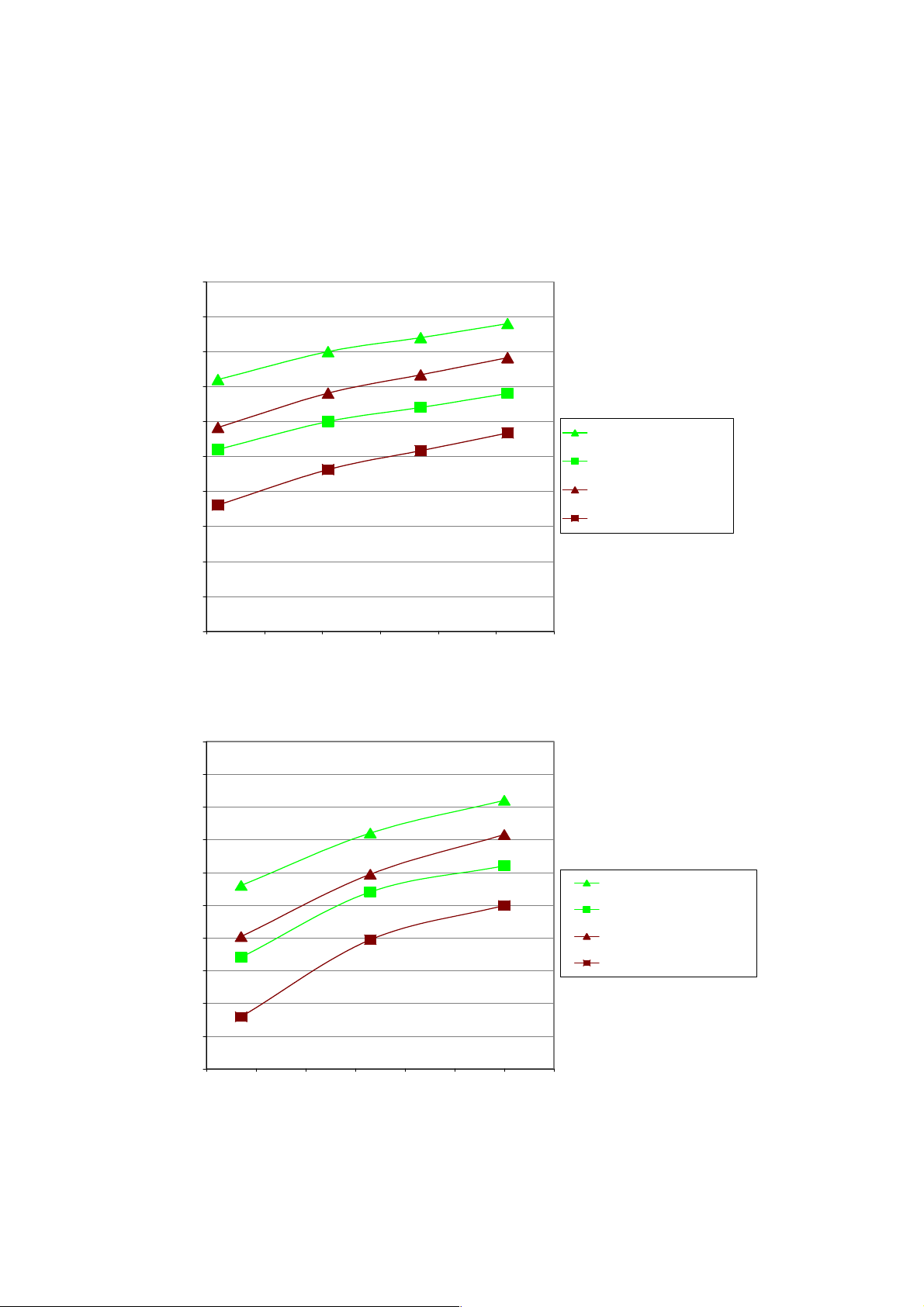
For highest operating temperatures (C-, I-Style) please refer to the following
diagrams. There are two diagrams for both uTCA carriers the 2000 and the
3000 series:
ASLP11 in uTCA-2000
70,0
65,0
60,0
55,0
50,0
45,0
40,0
air in t emperature
35,0
30,0
25,0
20,0
1,21,31,41,51,61,71,8
air speed within slot
70,0
65,0
60,0
55,0
- measured with fan_ctl=5, 6, 7, 8
- fan_ctl=6 is 82% fan speed default (1.4 m/s)
- with 'dirty' air filter
- up to 500m above sea level
- single board in slot 1
- two boards in slot 1+7
PS 28.02.2008
1.5GHz one core TDP
1.5GHz both cores TDP
two 1.5GHz one core TDP
two 1.5GHz both cores TDP
ASLP11 in uTCA-3000
- measured with fan_ctl=55d, 81d, 100d
- fan_ctl=81d is 82% fan speed default (1.3 m/s)
- up to 500m above sea level
- single board in slot 2
- two boards in slot 2+4
PS 3.03.2008
50,0
45,0
40,0
air i n temperature
35,0
30,0
25,0
20,0
1 1,1 1,2 1,3 1,4 1,5 1,6 1,7
air speed within slot
1.5GHz one core TDP
1.5GHz both cores TDP
two 1.5GHz one core TDP
two 1.5GHz both cores TDP
GE Intelligent Platforms – ASLP11 Hardware Reference Manual, Third Edition Page 56
Page 57

Electrical Characteristics
• The core temperature of the CPU can be read out via the onboard
temperature sensor. The value must be kept below 100°C for all
operating conditions. This value is already included in the airspeed
diagram above. If this temperature limit is violated, the CPU will start to
reduce its internal frequency temporarily. This can be checked by a short
blink of the red LED which occurs every 0.8 seconds.
Supply voltage range
The following ranges are defined by the AMC.0 specification. The voltages
have to be measured at the ASLP11 board (for example at the AMC
connector pins):
Table 18: Supply voltage ranges
Supply Voltage and tolerance
+3.3 V 3.3 V +/-10 %
+12 V 10.8 V – 13.2 V
Isolation
By itself the onboard digital ground GND and the front panel/chassis frame
ground FGND are isolated on the ASLP11 with a layout distance of more
than 0.8 mm in all PCB layers. However, most standard USB devices will
connect FGND with GND directly in the device. Also standard racks (our
starter cage too) connect both grounds at the power supply for safety reasons.
GE Intelligent Platforms – ASLP11 Hardware Reference Manual, Third Edition Page 57
Page 58
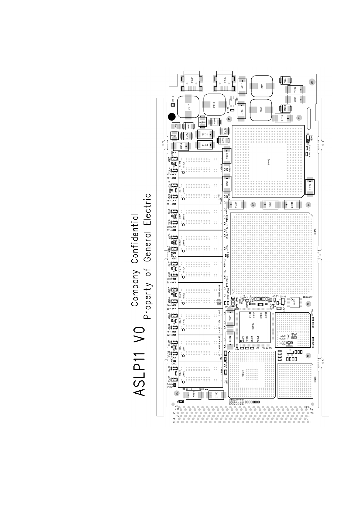
Placement Plan Component Side ASLP11 V0
Figure 3: Placement plan component side, V0
GE Intelligent Platforms – ASLP11 Hardware Reference Manual, Third Edition Page 58
Page 59
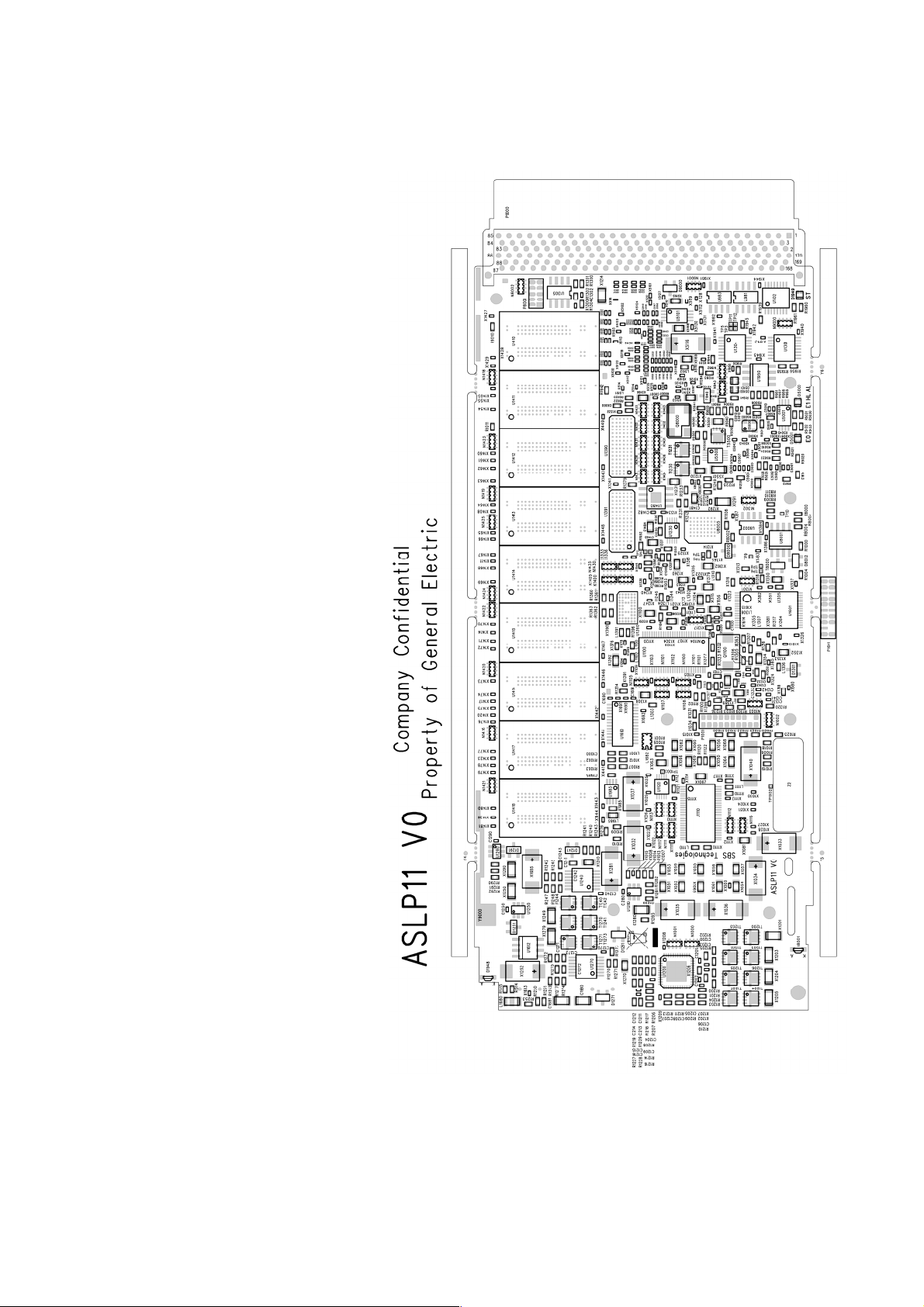
Placement Plan Solder Side ASLP11 V0
Figure 4: Placement plan solder side, V0
GE Intelligent Platforms – ASLP11 Hardware Reference Manual, Third Edition Page 59
Page 60

Page 61

Appendix A Support and Warranty Information
Chapter Scope
The following section describes GE Intelligent Platforms’ product support
program. In this chapter you will find information about our product warranty
terms and details about what action to take if you experience a problem with
the product.
Geographical Regions
World-wide headquarter of GE Intelligent Platforms, Inc. is at
GE Intelligent Platforms Inc.
2500 Austin Drive
Charlottesville, VA 22911
U.S.A.
Web: http://www.ge-ip.com
GE Intelligent Platforms, Inc. uses two regional headquarters for the purpose
of support, service, RMA returns and other functions.
Regional areas:
WW world-wide
EU Germany: Augsburg
UK: Towcester
US Americas & Pacific Rim (Japan, Korea, China, Philippines,
AUS, NZ)
Technical Support
If you should have a problem with a GE Intelligent Platforms product: Free
technical support is available by phone, fax or email. Telephone support is
available at main locations or at the regional center where the product was
bought.
GE Intelligent Platforms – ASLP11 Hardware Reference Manual, Third Edition Page 61
Page 62

Germany US
Support on the Web
Warranty
Error Report
Monday through Thursday
8:00 – 17:00 (CET)
Friday
8:00 – 16:00 (CET)
Phone +49-821-5034-170
Fax +49-821-5034-119
E-Mail
Monday through Friday
8:30 AM – 5:30 PM (Eastern Time)
Phone +1-800-322-3616
Fax +1E-Mail
For support and information, visit our website at
http://www.ge-ip.com
Information for components, corresponding driver software, etc. can also be
found at the following locations:
AMD Corp. www.amd.com
American Megatrends www.ami.com
Fedora www.fedora.redhat.com
IBM Corp. www.ibm.com
Intel Corp. www.intel.com
Linear Technology www.linear-tech.com
Microsoft Corp. www.microsoft.com
Freescale Corp. www.freescale.com
Novell www.novell.com
NVIDIA www.nvidia.com
Pericom www.pericom.com
PCI Industrial Computer Manufacturing Group www.picmg.org
PLX Technology www.plxtech.com
QNX Software Systems www.qnx.com
Red Hat www.redhat.com
Symbios Logic www.lsilogic.com
VITA www.vita.com
Wind River Systems www.windriver.com
For detailed warranty information, visit our website at
http://www.ge-ip.com
For error reports and RMA (Return Material Authorization) forms contact
these email addresses:
In case of difficulties provide at least the information listed below to an
appropriate support center or on their web site as listed above:
• RMA Number, if applicable
• Product & Serial Number
• Part Number
• Version
• Contact: Name & Phone Number
• Detailed Description of the Problem/Defect
GE Intelligent Platforms – ASLP11 Hardware Reference Manual, Third Edition Page 62
Page 63

GE Intelligent Platforms – ASLP11 Hardware Reference Manual, Third Edition Page 63
Page 64

© 2010 GE Intelligent Platforms Embedded
Systems, Inc. All rights reserved.
* indicates a trademark of GE Intelligent
Platforms, Inc. and/or its affiliates. All other
trademarks are the property of their respective
owners.
Confidential Information - This document
contains Confidential/Proprietary Information
of GE Intelligent Platforms, Inc. and/or its
suppliers or vendors. Distribution or
reproduction prohibited without permission.
THIS DOCUMENT AND ITS CONTENTS ARE
PROVIDED "AS IS", WITH NO REPRESENTATIONS
OR WARRANTIES OF ANY KIND, WHETHER
EXPRESS OR IMPLIED, INCLUDING BUT NOT
LIMITED TO WARRANTIES OF DESIGN,
MERCHANTABILITY, OR FITNESS FOR A
PARTICULAR PURPOSE. ALL OTHER LIABILITY
ARISING FROM RELIANCE UPON ANY
INFORMATION CONTAINED HEREIN IS
EXPRESSLY DISCLAIMED.
GE Intelligent Platforms
Information Centers
Americas:
1 800 322 3616 or 1 256 880 0444
Asia Pacific:
86 10 6561 1561
Europe, Middle East and Africa:
Germany +49 821 5034-0
UK +44 1327 359444
Additional Resources
For more information, please visit
the GE Intelligent Platforms Embedded Systems
web site at:
www.ge-ip.com
Publication No. ASLP113E
 Loading...