

Page 1

GE Healthcare
Solar™ 8000M/i patient monitor
Service Manual
Software Version 5
Solar™ 8000M/i patient monitor
English
2026266-004 (CD)
2026264-042C (paper)
© 2007 General Electric Company
All rights reserved.
Page 2

NOTE: The information in this manual applies to Solar 8000i and Solar 8000M Patient Monitors. Due to
continuing product innovation, specifications in this manual are subject to change without notice.
NOTE: For technical documentation purposes, the abbreviation GE is used for the legal entity name, GE
Medical Systems Information Technologies.
Listed below are GE Medical Systems Information Technologies trademarks. All other trademarks contained
herein are the property of their respective owners.
APEX, DASH, MUSE, RSVP, SOLAR, TRAM, TRIM KNOB, and UNITY NETWORK are trademarks of GE
Medical Systems Information Technologies registered in the United States Patent and Trademark Office.
CARESCAPE is a trademark of GE Medical Systems Information Technologies.
T-2 Solar 8000M/i patient monitor 2026265-075C
30 November 2007
Page 3

Contents
1 Introduction . . . . . . . . . . . . . . . . . . . . . . . . . . . . . . . . . . . . 1-1
Manual information . . . . . . . . . . . . . . . . . . . . . . . . . . . . . . . . . . . . . . . . . . . . . . . . . . 1-2
Revision history . . . . . . . . . . . . . . . . . . . . . . . . . . . . . . . . . . . . . . . . . . . . . . . . . . . 1-2
Intended use . . . . . . . . . . . . . . . . . . . . . . . . . . . . . . . . . . . . . . . . . . . . . . . . . . . . . 1-2
Intended audience . . . . . . . . . . . . . . . . . . . . . . . . . . . . . . . . . . . . . . . . . . . . . . . . .1-2
Ordering manuals . . . . . . . . . . . . . . . . . . . . . . . . . . . . . . . . . . . . . . . . . . . . . . . . .1-2
Safety information . . . . . . . . . . . . . . . . . . . . . . . . . . . . . . . . . . . . . . . . . . . . . . . . . . . 1-3
Responsibility of the manufacturer . . . . . . . . . . . . . . . . . . . . . . . . . . . . . . . . . . . . . 1-3
General . . . . . . . . . . . . . . . . . . . . . . . . . . . . . . . . . . . . . . . . . . . . . . . . . . . . . . . . . 1-3
Warnings, cautions, and notes . . . . . . . . . . . . . . . . . . . . . . . . . . . . . . . . . . . . . . . . 1-4
Equipment symbols . . . . . . . . . . . . . . . . . . . . . . . . . . . . . . . . . . . . . . . . . . . . . . . . 1-5
Service information . . . . . . . . . . . . . . . . . . . . . . . . . . . . . . . . . . . . . . . . . . . . . . . . . . 1-7
Service requirements . . . . . . . . . . . . . . . . . . . . . . . . . . . . . . . . . . . . . . . . . . . . . . . 1-7
Equipment identification . . . . . . . . . . . . . . . . . . . . . . . . . . . . . . . . . . . . . . . . . . . . . 1-7
2 Equipment overview . . . . . . . . . . . . . . . . . . . . . . . . . . . . . 2-1
System components . . . . . . . . . . . . . . . . . . . . . . . . . . . . . . . . . . . . . . . . . . . . . . . . . 2-2
Solar 8000M/i patient monitoring system . . . . . . . . . . . . . . . . . . . . . . . . . . . . . . . . 2-2
Solar 8000M/i patient monitor . . . . . . . . . . . . . . . . . . . . . . . . . . . . . . . . . . . . . . . . 2-3
iPanel computer . . . . . . . . . . . . . . . . . . . . . . . . . . . . . . . . . . . . . . . . . . . . . . . . . . . 2-4
UnityView remote display controller . . . . . . . . . . . . . . . . . . . . . . . . . . . . . . . . . . . . 2-4
Tram-rac housing . . . . . . . . . . . . . . . . . . . . . . . . . . . . . . . . . . . . . . . . . . . . . . . . . . 2-5
Patient Data Module (PDM) . . . . . . . . . . . . . . . . . . . . . . . . . . . . . . . . . . . . . . . . . . 2-6
Connectivity devices . . . . . . . . . . . . . . . . . . . . . . . . . . . . . . . . . . . . . . . . . . . . . . . 2-6
PRN 50/PRN 50-M digital writer . . . . . . . . . . . . . . . . . . . . . . . . . . . . . . . . . . . . . .2-7
Laser printer . . . . . . . . . . . . . . . . . . . . . . . . . . . . . . . . . . . . . . . . . . . . . . . . . . . . . . 2-7
Remote control or keypad . . . . . . . . . . . . . . . . . . . . . . . . . . . . . . . . . . . . . . . . . . . 2-8
Remote displays . . . . . . . . . . . . . . . . . . . . . . . . . . . . . . . . . . . . . . . . . . . . . . . . . .2-8
Device compatibility . . . . . . . . . . . . . . . . . . . . . . . . . . . . . . . . . . . . . . . . . . . . . . . . . 2-9
Acquisition modules . . . . . . . . . . . . . . . . . . . . . . . . . . . . . . . . . . . . . . . . . . . . . . . . 2-9
Peripheral devices . . . . . . . . . . . . . . . . . . . . . . . . . . . . . . . . . . . . . . . . . . . . . . . .2-10
Unity Network devices . . . . . . . . . . . . . . . . . . . . . . . . . . . . . . . . . . . . . . . . . . . . .2-11
Interfacing with other peripheral devices . . . . . . . . . . . . . . . . . . . . . . . . . . . . . . .2-12
Theory of operation . . . . . . . . . . . . . . . . . . . . . . . . . . . . . . . . . . . . . . . . . . . . . . . . . 2-13
Block diagram of internal connections . . . . . . . . . . . . . . . . . . . . . . . . . . . . . . . . . 2-14
Processor board . . . . . . . . . . . . . . . . . . . . . . . . . . . . . . . . . . . . . . . . . . . . . . . . . . 2-15
Power supply . . . . . . . . . . . . . . . . . . . . . . . . . . . . . . . . . . . . . . . . . . . . . . . . . . . .2-22
Speaker . . . . . . . . . . . . . . . . . . . . . . . . . . . . . . . . . . . . . . . . . . . . . . . . . . . . . . . . 2-22
2026265-075C Solar 8000M/i patient monitor i
Page 4

3 Installation . . . . . . . . . . . . . . . . . . . . . . . . . . . . . . . . . . . . . 3-1
Back panel connections . . . . . . . . . . . . . . . . . . . . . . . . . . . . . . . . . . . . . . . . . . . . . . 3-2
TRAM-NET . . . . . . . . . . . . . . . . . . . . . . . . . . . . . . . . . . . . . . . . . . . . . . . . . . . . . .3-3
ETHERNET . . . . . . . . . . . . . . . . . . . . . . . . . . . . . . . . . . . . . . . . . . . . . . . . . . . . . . 3-5
VGA VID 1 and 2 . . . . . . . . . . . . . . . . . . . . . . . . . . . . . . . . . . . . . . . . . . . . . . . . . .3-5
DFP VID 1 and 2 . . . . . . . . . . . . . . . . . . . . . . . . . . . . . . . . . . . . . . . . . . . . . . . . . . 3-6
RS-232 1 . . . . . . . . . . . . . . . . . . . . . . . . . . . . . . . . . . . . . . . . . . . . . . . . . . . . . . . . 3-6
RS-232 2 . . . . . . . . . . . . . . . . . . . . . . . . . . . . . . . . . . . . . . . . . . . . . . . . . . . . . . . . 3-6
Front panel connectors and indicators . . . . . . . . . . . . . . . . . . . . . . . . . . . . . . . . . . 3-7
M-Ports . . . . . . . . . . . . . . . . . . . . . . . . . . . . . . . . . . . . . . . . . . . . . . . . . . . . . . . . .3-7
Indicators . . . . . . . . . . . . . . . . . . . . . . . . . . . . . . . . . . . . . . . . . . . . . . . . . . . . . . .3-10
Power up . . . . . . . . . . . . . . . . . . . . . . . . . . . . . . . . . . . . . . . . . . . . . . . . . . . . . . . . . . 3-10
TRAM-NET communication . . . . . . . . . . . . . . . . . . . . . . . . . . . . . . . . . . . . . . . . . . 3-11
Overview . . . . . . . . . . . . . . . . . . . . . . . . . . . . . . . . . . . . . . . . . . . . . . . . . . . . . . . 3-11
Internal hub . . . . . . . . . . . . . . . . . . . . . . . . . . . . . . . . . . . . . . . . . . . . . . . . . . . . . 3-11
Ethernet communication . . . . . . . . . . . . . . . . . . . . . . . . . . . . . . . . . . . . . . . . . . . . . 3-12
About ethernet . . . . . . . . . . . . . . . . . . . . . . . . . . . . . . . . . . . . . . . . . . . . . . . . . . .3-12
Twisted pair . . . . . . . . . . . . . . . . . . . . . . . . . . . . . . . . . . . . . . . . . . . . . . . . . . . . . 3-12
Network terms . . . . . . . . . . . . . . . . . . . . . . . . . . . . . . . . . . . . . . . . . . . . . . . . . . . 3-13
4 Maintenance and checkout . . . . . . . . . . . . . . . . . . . . . . . 4-1
Maintenance schedule . . . . . . . . . . . . . . . . . . . . . . . . . . . . . . . . . . . . . . . . . . . . . . . 4-2
Manufacturer recommendations . . . . . . . . . . . . . . . . . . . . . . . . . . . . . . . . . . . . . . 4-2
Manufacturer responsibility . . . . . . . . . . . . . . . . . . . . . . . . . . . . . . . . . . . . . . . . . . 4-2
Preventive maintenance . . . . . . . . . . . . . . . . . . . . . . . . . . . . . . . . . . . . . . . . . . . .4-2
Visual inspection . . . . . . . . . . . . . . . . . . . . . . . . . . . . . . . . . . . . . . . . . . . . . . . . . . . . 4-3
Cleaning . . . . . . . . . . . . . . . . . . . . . . . . . . . . . . . . . . . . . . . . . . . . . . . . . . . . . . . . . . . 4-4
Cleaning precautions . . . . . . . . . . . . . . . . . . . . . . . . . . . . . . . . . . . . . . . . . . . . . . . 4-4
Exterior cleaning . . . . . . . . . . . . . . . . . . . . . . . . . . . . . . . . . . . . . . . . . . . . . . . . . . 4-4
Cleaning, disinfecting and storing GE ECG cables and leadwires . . . . . . . . . . . . 4-5
Electrical safety tests . . . . . . . . . . . . . . . . . . . . . . . . . . . . . . . . . . . . . . . . . . . . . . . . 4-8
Recommendations . . . . . . . . . . . . . . . . . . . . . . . . . . . . . . . . . . . . . . . . . . . . . . . . . 4-8
Set up . . . . . . . . . . . . . . . . . . . . . . . . . . . . . . . . . . . . . . . . . . . . . . . . . . . . . . . . . . . 4-9
Power outlet test . . . . . . . . . . . . . . . . . . . . . . . . . . . . . . . . . . . . . . . . . . . . . . . . . . 4-9
Ground (earth) integrity . . . . . . . . . . . . . . . . . . . . . . . . . . . . . . . . . . . . . . . . . . . . . 4-9
Ground (earth) wire leakage current tests . . . . . . . . . . . . . . . . . . . . . . . . . . . . . .4-11
Enclosure leakage current test . . . . . . . . . . . . . . . . . . . . . . . . . . . . . . . . . . . . . .4-12
Patient (source) leakage current test . . . . . . . . . . . . . . . . . . . . . . . . . . . . . . . . . . 4-13
Patient (sink) leakage current test . . . . . . . . . . . . . . . . . . . . . . . . . . . . . . . . . . . .4-14
Test completion . . . . . . . . . . . . . . . . . . . . . . . . . . . . . . . . . . . . . . . . . . . . . . . . . . 4-15
ii Solar 8000M/i patient monitor 2026265-075C
Page 5

Checkout procedure . . . . . . . . . . . . . . . . . . . . . . . . . . . . . . . . . . . . . . . . . . . . . . . . 4-16
General . . . . . . . . . . . . . . . . . . . . . . . . . . . . . . . . . . . . . . . . . . . . . . . . . . . . . . . . 4-16
Required tools and equipment . . . . . . . . . . . . . . . . . . . . . . . . . . . . . . . . . . . . . . . 4-16
Set up . . . . . . . . . . . . . . . . . . . . . . . . . . . . . . . . . . . . . . . . . . . . . . . . . . . . . . . . . . 4-17
Procedures . . . . . . . . . . . . . . . . . . . . . . . . . . . . . . . . . . . . . . . . . . . . . . . . . . . . . . 4-18
Parameter tests . . . . . . . . . . . . . . . . . . . . . . . . . . . . . . . . . . . . . . . . . . . . . . . . . . 4-22
Completion . . . . . . . . . . . . . . . . . . . . . . . . . . . . . . . . . . . . . . . . . . . . . . . . . . . . . . 4-36
Maintenance Checklist . . . . . . . . . . . . . . . . . . . . . . . . . . . . . . . . . . . . . . . . . . . . . . 4-37
“Visual inspection” on page 4-3 . . . . . . . . . . . . . . . . . . . . . . . . . . . . . . . . . . . . . .4-37
“Cleaning” on page 4-4 . . . . . . . . . . . . . . . . . . . . . . . . . . . . . . . . . . . . . . . . . . . . 4-37
“Electrical safety tests” on page 4-8 . . . . . . . . . . . . . . . . . . . . . . . . . . . . . . . . . . . 4-37
“Checkout procedure” on page 4-16 . . . . . . . . . . . . . . . . . . . . . . . . . . . . . . . . . . 4-37
Repair Log . . . . . . . . . . . . . . . . . . . . . . . . . . . . . . . . . . . . . . . . . . . . . . . . . . . . . . . . 4-39
5 Troubleshooting . . . . . . . . . . . . . . . . . . . . . . . . . . . . . . . . 5-1
Terms used . . . . . . . . . . . . . . . . . . . . . . . . . . . . . . . . . . . . . . . . . . . . . . . . . . . . . . . . . 5-2
Abort (main code) . . . . . . . . . . . . . . . . . . . . . . . . . . . . . . . . . . . . . . . . . . . . . . . . .5-2
Boot loader or boot code . . . . . . . . . . . . . . . . . . . . . . . . . . . . . . . . . . . . . . . . . . . . 5-2
Cold start . . . . . . . . . . . . . . . . . . . . . . . . . . . . . . . . . . . . . . . . . . . . . . . . . . . . . . . . 5-2
Continue (main code) . . . . . . . . . . . . . . . . . . . . . . . . . . . . . . . . . . . . . . . . . . . . . . . 5-2
Monitor memory . . . . . . . . . . . . . . . . . . . . . . . . . . . . . . . . . . . . . . . . . . . . . . . . . . . 5-3
Protected memory . . . . . . . . . . . . . . . . . . . . . . . . . . . . . . . . . . . . . . . . . . . . . . . . . 5-3
Power cycle or reboot . . . . . . . . . . . . . . . . . . . . . . . . . . . . . . . . . . . . . . . . . . . . . . 5-3
Service mode (main code) . . . . . . . . . . . . . . . . . . . . . . . . . . . . . . . . . . . . . . . . . . . 5-3
Service menu (boot code) . . . . . . . . . . . . . . . . . . . . . . . . . . . . . . . . . . . . . . . . . . . 5-3
Warm start (boot code) . . . . . . . . . . . . . . . . . . . . . . . . . . . . . . . . . . . . . . . . . . . . . 5-3
Country selection . . . . . . . . . . . . . . . . . . . . . . . . . . . . . . . . . . . . . . . . . . . . . . . . . . 5-3
Set language . . . . . . . . . . . . . . . . . . . . . . . . . . . . . . . . . . . . . . . . . . . . . . . . . . . . . 5-3
Service menus . . . . . . . . . . . . . . . . . . . . . . . . . . . . . . . . . . . . . . . . . . . . . . . . . . . . . . 5-4
Boot code Service Menu . . . . . . . . . . . . . . . . . . . . . . . . . . . . . . . . . . . . . . . . . . . . 5-4
Main code SERVICE MODE menu . . . . . . . . . . . . . . . . . . . . . . . . . . . . . . . . . . . . 5-6
Fault analysis . . . . . . . . . . . . . . . . . . . . . . . . . . . . . . . . . . . . . . . . . . . . . . . . . . . . . . 5-10
Overview . . . . . . . . . . . . . . . . . . . . . . . . . . . . . . . . . . . . . . . . . . . . . . . . . . . . . . . 5-10
Calibration . . . . . . . . . . . . . . . . . . . . . . . . . . . . . . . . . . . . . . . . . . . . . . . . . . . . . . 5-10
AC line voltage test . . . . . . . . . . . . . . . . . . . . . . . . . . . . . . . . . . . . . . . . . . . . . . . . . 5-11
120 VAC, 50/60 Hz . . . . . . . . . . . . . . . . . . . . . . . . . . . . . . . . . . . . . . . . . . . . . . . 5-11
240 VAC, 50/60 Hz . . . . . . . . . . . . . . . . . . . . . . . . . . . . . . . . . . . . . . . . . . . . . . . 5-11
Troubleshooting procedure . . . . . . . . . . . . . . . . . . . . . . . . . . . . . . . . . . . . . . . . . . 5-12
Problems and solutions . . . . . . . . . . . . . . . . . . . . . . . . . . . . . . . . . . . . . . . . . . . . 5-13
LED troubleshooting . . . . . . . . . . . . . . . . . . . . . . . . . . . . . . . . . . . . . . . . . . . . . .5-16
Troubleshooting software updates . . . . . . . . . . . . . . . . . . . . . . . . . . . . . . . . . . . . 5-19
2026265-075C Solar 8000M/i patient monitor iii
Page 6

Error messages . . . . . . . . . . . . . . . . . . . . . . . . . . . . . . . . . . . . . . . . . . . . . . . . . . . . 5-20
Reviewing error/event logs . . . . . . . . . . . . . . . . . . . . . . . . . . . . . . . . . . . . . . . . . . . 5-22
Accessing error/event logs . . . . . . . . . . . . . . . . . . . . . . . . . . . . . . . . . . . . . . . . . . 5-22
Useful error data . . . . . . . . . . . . . . . . . . . . . . . . . . . . . . . . . . . . . . . . . . . . . . . . . 5-23
Get error logs . . . . . . . . . . . . . . . . . . . . . . . . . . . . . . . . . . . . . . . . . . . . . . . . . . . . . . 5-27
Get logs via PC using netUpdate . . . . . . . . . . . . . . . . . . . . . . . . . . . . . . . . . . . . . 5-27
6 Configuration . . . . . . . . . . . . . . . . . . . . . . . . . . . . . . . . . . . 6-1
Configuring a patient monitor . . . . . . . . . . . . . . . . . . . . . . . . . . . . . . . . . . . . . . . . . 6-2
General . . . . . . . . . . . . . . . . . . . . . . . . . . . . . . . . . . . . . . . . . . . . . . . . . . . . . . . . . 6-2
Set unit name . . . . . . . . . . . . . . . . . . . . . . . . . . . . . . . . . . . . . . . . . . . . . . . . . . . . . 6-3
Set bed number . . . . . . . . . . . . . . . . . . . . . . . . . . . . . . . . . . . . . . . . . . . . . . . . . . .6-3
Patient monitor type . . . . . . . . . . . . . . . . . . . . . . . . . . . . . . . . . . . . . . . . . . . . . . . . 6-4
Set graph locations . . . . . . . . . . . . . . . . . . . . . . . . . . . . . . . . . . . . . . . . . . . . . . . . 6-5
Admit Menu . . . . . . . . . . . . . . . . . . . . . . . . . . . . . . . . . . . . . . . . . . . . . . . . . . . . . . 6-6
Set line frequency . . . . . . . . . . . . . . . . . . . . . . . . . . . . . . . . . . . . . . . . . . . . . . . . . 6-7
Set defib sync voltage and pulse width . . . . . . . . . . . . . . . . . . . . . . . . . . . . . . . . . 6-7
Set country selection . . . . . . . . . . . . . . . . . . . . . . . . . . . . . . . . . . . . . . . . . . . . . . . 6-8
Set language . . . . . . . . . . . . . . . . . . . . . . . . . . . . . . . . . . . . . . . . . . . . . . . . . . . . . 6-8
Calibrate touchscreen . . . . . . . . . . . . . . . . . . . . . . . . . . . . . . . . . . . . . . . . . . . . . . 6-8
Completion . . . . . . . . . . . . . . . . . . . . . . . . . . . . . . . . . . . . . . . . . . . . . . . . . . . . . . . 6-8
Advanced user procedures . . . . . . . . . . . . . . . . . . . . . . . . . . . . . . . . . . . . . . . . . . . 6-9
Procedures . . . . . . . . . . . . . . . . . . . . . . . . . . . . . . . . . . . . . . . . . . . . . . . . . . . . . . . 6-9
Set time and date . . . . . . . . . . . . . . . . . . . . . . . . . . . . . . . . . . . . . . . . . . . . . . . . . . 6-9
Change software level . . . . . . . . . . . . . . . . . . . . . . . . . . . . . . . . . . . . . . . . . . . . .6-10
Enable options . . . . . . . . . . . . . . . . . . . . . . . . . . . . . . . . . . . . . . . . . . . . . . . . . . . 6-10
Transfer monitor defaults . . . . . . . . . . . . . . . . . . . . . . . . . . . . . . . . . . . . . . . . . . . 6-10
Change Ethernet address . . . . . . . . . . . . . . . . . . . . . . . . . . . . . . . . . . . . . . . . . . 6-14
Set internet address . . . . . . . . . . . . . . . . . . . . . . . . . . . . . . . . . . . . . . . . . . . . . . . 6-15
Power cycle . . . . . . . . . . . . . . . . . . . . . . . . . . . . . . . . . . . . . . . . . . . . . . . . . . . . . 6-16
7 Field replaceable units . . . . . . . . . . . . . . . . . . . . . . . . . . . 7-1
Ordering parts . . . . . . . . . . . . . . . . . . . . . . . . . . . . . . . . . . . . . . . . . . . . . . . . . . . . . . 7-2
Field replaceable units . . . . . . . . . . . . . . . . . . . . . . . . . . . . . . . . . . . . . . . . . . . . . . . 7-3
Hardware kit . . . . . . . . . . . . . . . . . . . . . . . . . . . . . . . . . . . . . . . . . . . . . . . . . . . . . . . . 7-4
Keypads and remote controls . . . . . . . . . . . . . . . . . . . . . . . . . . . . . . . . . . . . . . . . . 7-6
Cables . . . . . . . . . . . . . . . . . . . . . . . . . . . . . . . . . . . . . . . . . . . . . . . . . . . . . . . . . . . . . 7-6
iv Solar 8000M/i patient monitor 2026265-075C
Page 7

Disassembly . . . . . . . . . . . . . . . . . . . . . . . . . . . . . . . . . . . . . . . . . . . . . . . . . . . . . . . . 7-7
Guidelines . . . . . . . . . . . . . . . . . . . . . . . . . . . . . . . . . . . . . . . . . . . . . . . . . . . . . . . 7-7
Disassembly procedures . . . . . . . . . . . . . . . . . . . . . . . . . . . . . . . . . . . . . . . . . . . . 7-8
Appendix A – Technical specifications . . . . . . . . . . . . . . A-1
Solar 8000M/i patient monitor . . . . . . . . . . . . . . . . . . . . . . . . . . . . . . . . . . . . . . . . . . A-2
Tram-rac 2 and 4A module housings . . . . . . . . . . . . . . . . . . . . . . . . . . . . . . . . . . . . A-5
Tram modules and Solar parameter functionality . . . . . . . . . . . . . . . . . . . . . . . . . A-7
Dual temperature module (400 and 700 series) . . . . . . . . . . . . . . . . . . . . . . . . . . A-15
Capnostat mainstream CO
module . . . . . . . . . . . . . . . . . . . . . . . . . . . . . . . . . . . . . . . . . . . . . . . . . . . . . . A-18
SvO
2
ICG module . . . . . . . . . . . . . . . . . . . . . . . . . . . . . . . . . . . . . . . . . . . . . . . . . . . . . . . . A-19
BIS/EEG module . . . . . . . . . . . . . . . . . . . . . . . . . . . . . . . . . . . . . . . . . . . . . . . . . . . . A-20
Patient Data Module . . . . . . . . . . . . . . . . . . . . . . . . . . . . . . . . . . . . . . . . . . . . . . . . . A-21
Solar SpO
Solar 8000M/i display . . . . . . . . . . . . . . . . . . . . . . . . . . . . . . . . . . . . . . . . . . . . . . . A-22
Masimo SET module . . . . . . . . . . . . . . . . . . . . . . . . . . . . . . . . . . . . . . A-21
2
Purchaser’s responsibility . . . . . . . . . . . . . . . . . . . . . . . . . . . . . . . . . . . . . . . . . .A-22
Medical-grade displays . . . . . . . . . . . . . . . . . . . . . . . . . . . . . . . . . . . . . . . . . . . .A-22
Non-medical grade displays . . . . . . . . . . . . . . . . . . . . . . . . . . . . . . . . . . . . . . . . .A-23
Required specifications for non-medical grade CRT displays . . . . . . . . . . . . . . .A-24
Recommended specifications for non-medical grade CRT displays . . . . . . . . . .A-25
Required specifications for non-medical grade digital flat panel displays . . . . . .A-26
Recommended specifications for non-medical grade digital flat panel displays .A-27
module . . . . . . . . . . . . . . . . . . . . . . . . . . . . . . . . . . . A-16
2
Appendix B – Electromagnetic compatibility . . . . . . . . . B-1
Electromagnetic compatibility (EMC) . . . . . . . . . . . . . . . . . . . . . . . . . . . . . . . . . . . B-2
Guidance and manufacturer’s declaration — electromagnetic emissions . . . . . . .B-2
Guidance and manufacturer’s declaration — electromagnetic immunity . . . . . . . .B-3
Recommended separation distances . . . . . . . . . . . . . . . . . . . . . . . . . . . . . . . . . . .B-5
Compliant cables and accessories . . . . . . . . . . . . . . . . . . . . . . . . . . . . . . . . . . . .B-6
2026265-075C Solar 8000M/i patient monitor v
Page 8

vi Solar 8000M/i patient monitor 2026265-075C
Page 9

1 Introduction
2026265-075C Solar 8000M/i patient monitor 1-1
Page 10
Manual information
Revision history
Each page of the document has the document part number and revision
letter at the bottom of the page. The revision letter changes whenever
the document is updated.
Intended use
Introduction: Manual information
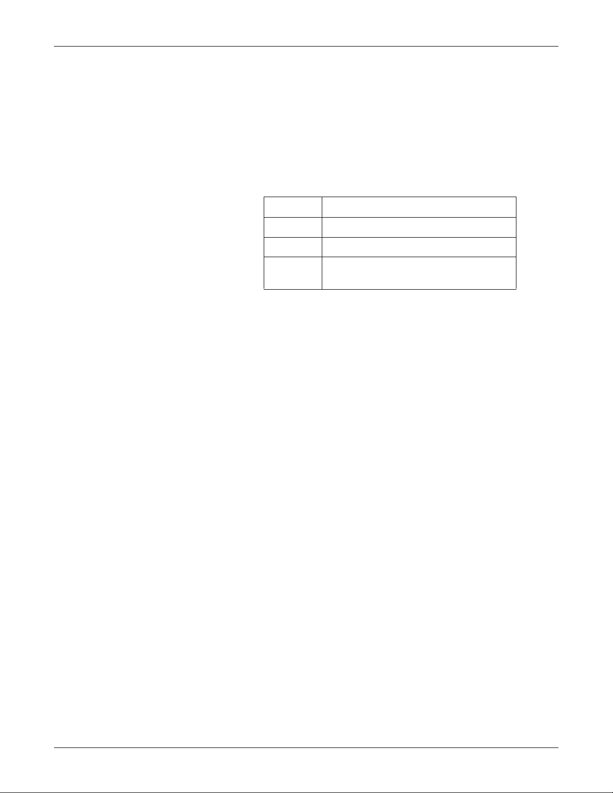
Revision Comment
A Initial release
B Updated document with editorial changes.
C Updated document with cpu and related hardware
changes.
Intended audience
Ordering manuals
This manual supplies technical information for service representatives
and technical personnel so they can maintain the equipment to the
assembly level. Use it as a guide for maintenance and electrical repairs
considered field repairable. Where necessary the manual identifies
additional sources of relevant information and technical assistance.
See the operator’s manual for the instructions necessary to operate the
equipment safely in accordance with its function and intended use.
This manual is intended for service representatives and technical
personnel who maintain, troubleshoot, or repair this equipment.
A paper copy of this manual will be provided upon request. Contact your
local GE representative and request the part number on the first page of
the manual.
1-2 Solar 8000M/i patient monitor 2026265-075C
Page 11

Introduction: Safety information
Safety information
Responsibility of the manufacturer
GE is responsible for the effects of safety, reliability, and performance
only if:
Assembly operations, extensions, readjustments, modifications, or
repairs are carried out by persons authorized by GE.
The electrical installation of the relevant room complies with the
requirements of the appropriate regulations.
The equipment is used in accordance with the instructions for use.
General
This device is intended for use under the direct supervision of a licensed
health care practitioner.
This device is not intended for home use.
Federal law restricts this device to be sold by or on the order of a
physician.
Contact GE for information before connecting any devices to the
equipment that are not recommended in this manual.
Parts and accessories used must meet the requirements of the applicable
EN 60601 series safety standards, and/or the system configuration must
meet the requirements of the EN 60601-1-1 medical electrical systems
standard.
Periodically, and whenever the integrity of the device is in doubt, test all
functions.
The use of accessory equipment not complying with the equivalent safety
requirements of this equipment may lead to a reduced level of safety of
the resulting system. Consideration relating to the choice shall include:
use of the accessory in the patient vicinity; and
evidence that the safety certification of the accessory has been
performed in accordance to the appropriate EN 60601-1 and/or EN
60601-1-1 harmonized national standard.
If the installation of the equipment, in the USA, will use 240V rather
than 120V, the source must be a center-tapped, 240V, single-phase
circuit.
2026265-075C Solar 8000M/i patient monitor 1-3
Page 12

Introduction: Safety information
Warnings, cautions, and notes
The terms danger, warning, and caution are used throughout this
manual to point out hazards and to designate a degree or level or
seriousness. Familiarize yourself with their definitions and significance.
Hazard is defined as a source of potential injury to a person.
DANGER indicates an imminent hazard which, if not avoided, will
result in death or serious injury.
WARNING indicates a potential hazard or unsafe practice which, if not
avoided, could result in death or serious injury.
CAUTION indicates a potential hazard or unsafe practice which, if not
avoided, could result in minor personal injury or product/property
damage.
NOTE provides application tips or other useful information to assure
that you get the most from your equipment.
1-4 Solar 8000M/i patient monitor 2026265-075C
Page 13
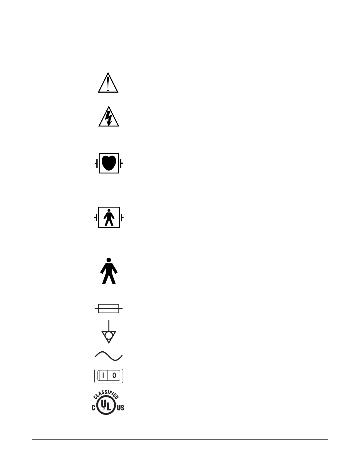
Equipment symbols
Introduction: Safety information
NOTE: Some symbols may not appear on all equipment.
ATTENTION: Consult accompanying documents.
CAUTION: To reduce the risk of electric shock, do not remove cover. Refer servicing to
qualified service personnel.
NOTE: The rating of protection against electric shock (indicated by symbol for CF or BF) is
achieved only when used with patient applied parts recommended by GE.
TYPE CF APPLIED PART: Isolated (floating) applied part suitable for intentional external and
internal application to the patient including direct cardiac application. “Paddles” outside the
box indicate the applied part is defibrillator proof.
[Medical Standard Definition:] F-type applied part (floating/isolated) complying with the
specified requirements of IEC/EN/UL 60601-1 Medical Standards to provide a higher degree
of protection against electric shock than that provided by type BF applied parts.
TYPE BF APPLIED PART: Isolated (floating) applied part suitable for intentional external and
internal application to the patient excluding direct cardiac application. “Paddles” outside the
box indicate the applied part is defibrillator proof.
[Medical Standard Definition:] F-type applied part (floating/isolated) complying with the
specified requirements of IEC/EN/UL 60601-1 Medical Standards to provide a higher degree
of protection against electric shock than that provided by type B applied parts.
TYPE B APPLIED PART: Non-isolated applied part suitable for intentional external and
internal application to the patient excluding direct cardiac application.
[Medical Standard Definition:] Applied part complying with the specified requirements of IEC/
EN/UL 60601-1 Medical Standards to provide protection against electric shock, particularly
regarding allowable leakage current.
Fuse
Equipotential Stud: A ground wire from another device can be tied here to ensure the devices
share a common reference.
Alternating current (AC)
Power; I = ON; O = OFF
Medical Equipment
With respect to electric shock, fire and mechanical hazards only in accordance with UL
60601-1, CAN/CSA C22.2 NO. 601.1, IEC 60601-1, IEC 60601-2-27, IEC 60601-2-30, IEC
4P41
2026265-075C Solar 8000M/i patient monitor 1-5
60601-2-34, and IEC 60601-2-49.
Page 14

2006-04
Introduction: Safety information
This symbol indicates that the waste of electrical and electronic equipment must not be
disposed as unsorted municipal waste and must be collected separately. Please contact an
authorized representative of the manufacturer for information concerning the
decommissioning of your equipment.
This symbol indicates the date of manufacture of this device. The first four digits identify the
year and the last two digits identify the month.
Non-ionizing electromagnetic radiation: To indicate elevated, potentially dangerous, levels of
non-ionizing radiation. Note - In case of application in a warning sign the rules according to
ISO 3864-1 shall be adhered to.
IEC 60878 note: See safety sign ISO 7010 - W005 “Warning, non-ionizing radiation”.
Manufacturer name and address.
European authorized representative.
NOTE
The following symbols (required by China law only) are
representative of what you may see on your equipment.
The number in the symbol indicates the EFUP period in years, as explained below. Check the
symbol on your equipment for its EFUP period.
This symbol indicates the product contains hazardous materials in excess of the limits
established by the Chinese standard SJ/T11363-2006 Requirements for Concentration Limits
for Certain Hazardous Substances in Electronic Information Products. The number in the
symbol is the Environment-friendly User Period (EFUP), which indicates the period during
which the toxic or hazardous substances or elements contained in electronic information
products will not leak or mutate under normal operating conditions so that the use of such
electronic information products will not result in any severe environmental pollution, any bodily
injury or damage to any assets. The unit of the period is “Year”.
In order to maintain the declared EFUP, the product shall be operated normally according to
the instructions and environmental conditions as defined in the product manual, and periodic
maintenance schedules specified in Product Maintenance Procedures shall be followed
strictly.
Consumables or certain parts may have their own label with an EFUP value less than the
product. Periodic replacement of those consumables or parts to maintain the declared EFUP
shall be done in accordance with the Product Maintenance Procedures. This product must not
be disposed of as unsorted municipal waste, and must be collected separately and handled
properly after decommissioning.
This symbol indicates that this electronic information product does not contain any toxic or
hazardous substance or elements above the maximum concentration value established by
the Chinese standard SJ/T11363-2006, and can be recycled after being discarded, and
should not be casually discarded.
1-6 Solar 8000M/i patient monitor 2026265-075C
Page 15
Service information
Service requirements
Follow the service requirements listed below.
Refer equipment servicing to GE authorized service personnel only.
Any unauthorized attempt to repair equipment under warranty voids
It is the user’s responsibility to report the need for service to GE or to
Failure on the part of the responsible individual, hospital, or
Regular maintenance, irrespective of usage, is essential to ensure
Equipment identification
Introduction: Service information
that warranty.
one of their authorized agents.
institution using this equipment to implement a satisfactory
maintenance schedule may cause undue equipment failure and
possible health hazards.
that the equipment will always be functional when required.
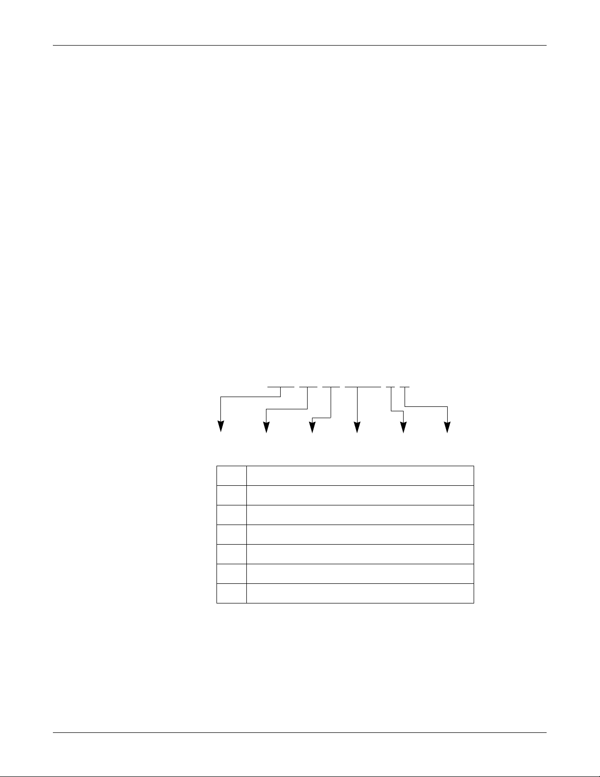
Every GE device has a unique serial number for identification. A sample
of the information found on a serial number label is shown below.
### ## ## #### # #
ABCDEF
Description
A product code
B year manufactured
C fiscal week manufactured
D production sequence number
E manufacturing site
F miscellaneous characteristic
2026265-075C Solar 8000M/i patient monitor 1-7
Page 16

Introduction: Service information
1-8 Solar 8000M/i patient monitor 2026265-075C
Page 17

2 Equipment overview
2026265-075C Solar 8000M/i patient monitor 2-1
Page 18

Equipment overview: System components
System components
Solar 8000M/i patient monitoring system
The Solar 8000M/i patient monitoring system consists of the following
standard components:
Solar 8000M/i processing unit
Display
Keypad and/or remote control
Two possible acquisition devices:
Tram-rac housing with acquisition module(s)
Patient Data Module (also referred to as PDM)
Optional components include:
iPanel™ computer
Clinical Information Center (central station)
Remote display, VGA and DFP
NOTE
Available on Solar 8000M and Solar 8000i patient monitors with
dual display capability.
Printer PRN 50/PRN 50-M
Unity Network™ ID connectivity device
2-2 Solar 8000M/i patient monitor 2026265-075C
Page 19
Equipment overview: System components
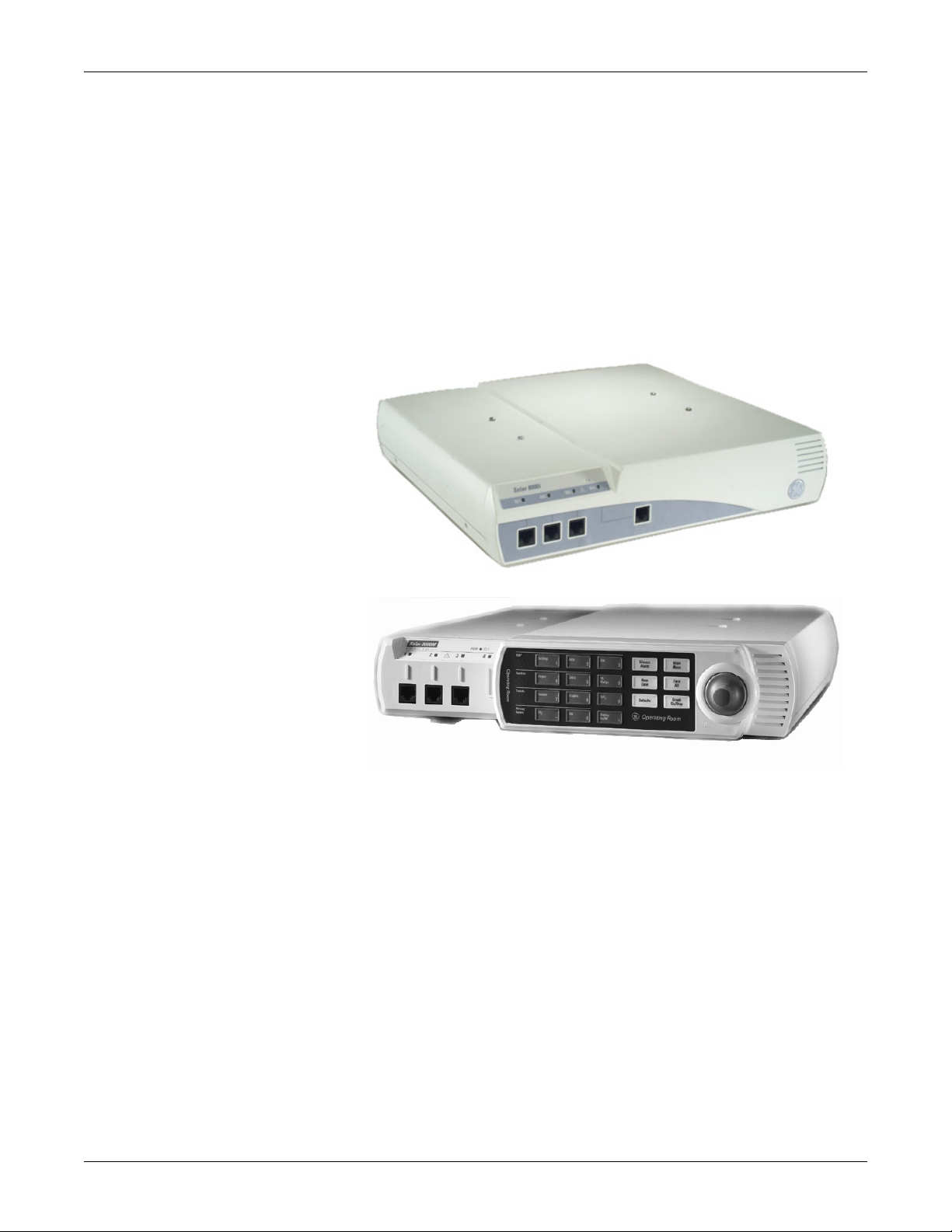
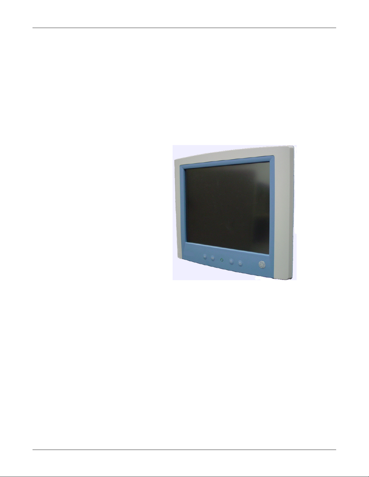
Solar 8000M/i patient monitor
The patient monitor consists of a Solar 8000M/i processing unit with
compatible display purchased from GE or another vendor.
The processing unit is the center of the Solar 8000M/i patient monitoring
system. It provides the user controls, the processors to communicate with
various patient monitoring modules, and it analyzes patient data. It can
display up to eight different waveforms at one time. System software
may be updated using a laptop computer connected to the Solar 8000M/i
processing unit or the Unity Network or from a Clinical Information
Center (CIC) on the Unity Network.
001C
042B
2026265-075C Solar 8000M/i patient monitor 2-3
Page 20
iPanel computer
Equipment overview: System components
The iPanel computer is a self contained medical grade computer with flat
panel display for use in the patient area. The iPanel contains the iPanel
software that provides one touch access to patient data on the enterprise
network. The iPanel application is compatible with the following patient
data web portals:
Centricity CIV
Centricity CV Cardiology Web
MUSE CV Web
Centricity Enterprise Web
UnityView remote display controller
The UnityView remote display controller consists of a remote display
controller with a compatible display purchased from GE or another
vendor. The controller connects to the Unity Network and may be
configured to display any patient waveforms broadcasted on the network
for better visibility as a remote full-view display, or as an in-room
telemetry display.
037A
2-4 Solar 8000M/i patient monitor 2026265-075C
Page 21
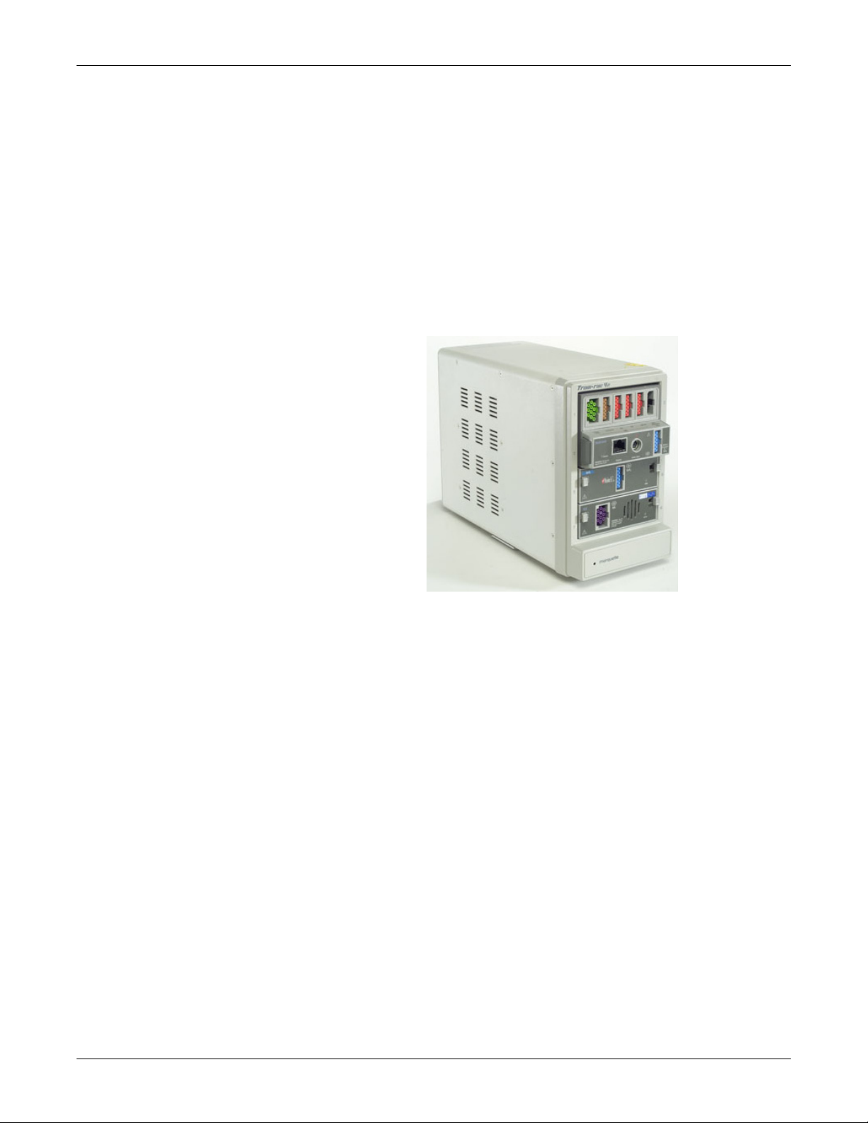
Tram-rac housing
Equipment overview: System components
The Tram-rac housing (remote acquisition case) acquires patient data for
the patient monitor. There are two Tram-rac housings available for the
monitor:
Tram-rac 2 housing — holds one Tram module.
Tram-rac 4A housing — holds one Tram module and two additional
single-high modules.
See the Tram-rac Housing Service Manual for additional information.
Shown below is a Tram-rac 4A housing with a Tram module and two
single parameter modules inserted.
005B
2026265-075C Solar 8000M/i patient monitor 2-5
Page 22
Equipment overview: System components
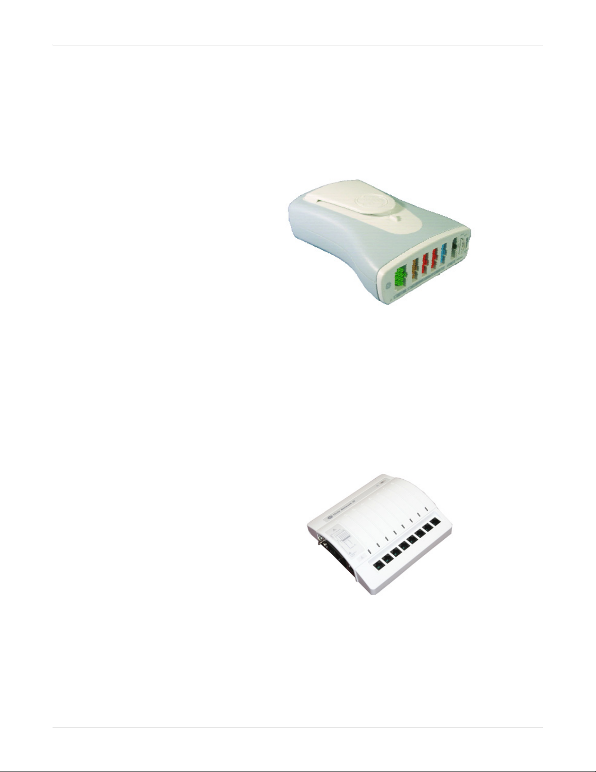
Patient Data Module (PDM)
The Patient Data Module (PDM) acquires patient data for the patient
monitor. See the Patient Data Module service manual for additional
information.
061A
Connectivity devices
The Unity Network ID connectivity device acquires digital data from
eight individually isolated serial ports. The data is collected from up to
eight peripheral devices (not necessarily manufactured by GE), then the
device transmits the formatted data to the Solar 8000M/i patient
monitor. See the appropriate connectivity device service manual for
additional information.
002B
2-6 Solar 8000M/i patient monitor 2026265-075C
Page 23
Equipment overview: System components
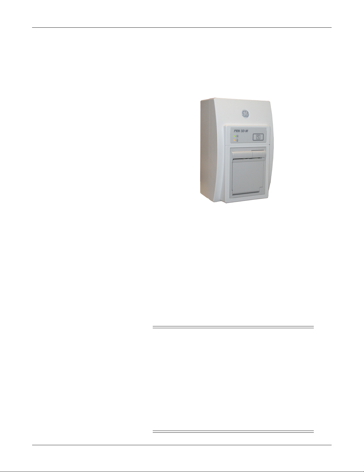
PRN 50/PRN 50-M digital writer
The PRN 50/PRN 50-M digital writer thermally records patient data on a
paper strip. Any parameter or trace that can be monitored on a monitor
can be graphed by the writer. Graphs initiate automatically when an
alarm is activated, or they can be initiated manually from the monitor.
Laser printer
003C
NOTE
The PRN 50-M digital writer is an M-Port device. To make an
AutoPort device (such as PRN 50) M-Port compatible, use the
AutoPort to M-Port adapter, pn 2001973-001.
An optional laser printer can be connected directly to the monitor via one
of the M-Ports. The laser printer must have a serial port, and an
interface adapter is required for the cable between the laser printer and
the monitor. Refer to the instructions provided in Laser Printer Support
Kit, pn 2013421-001, for details on the interface adapter and installing a
serial card in a laser printer.
WARNINGS
SHOCK HAZARD. Laser printers are UL 60950/EN
60950 certified equipment, which may not meet the
leakage current requirements of patient care equipment.
This equipment must not be located in the patient
vicinity unless the medical system standard EN
60601-1-1 is followed.
Do not connect a laser printer to a multiple portable
socket outlet (MPSO) supplying patient care equipment.
The use of an MPSO for a system will result in an
enclosure leakage current equal to the sum of all the
individual earth leakage currents of the system if there is
an interruption of the MPSO protective earth conductor.
2026265-075C Solar 8000M/i patient monitor 2-7
Page 24
Equipment overview: System components
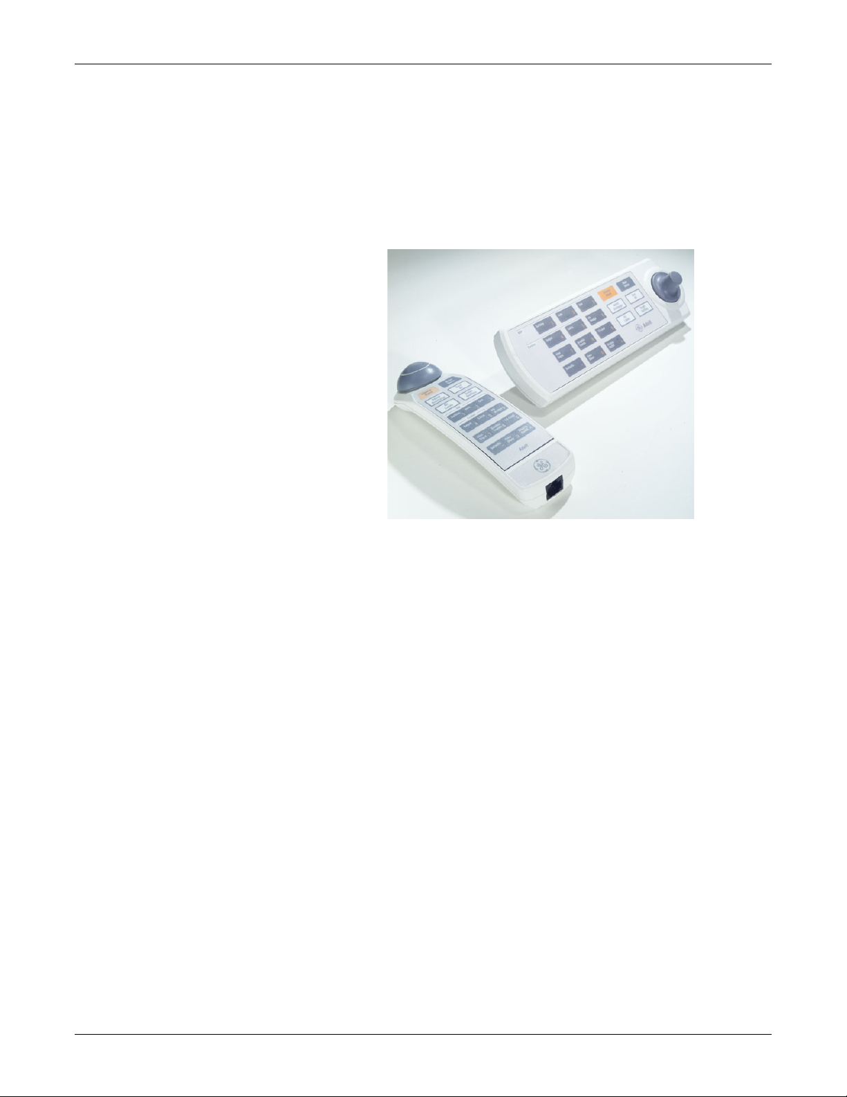
Remote control or keypad
The remote control or keypad provides all patient monitor controls on a
portable component with a TRIM KNOB control, and allows the user to
operate the patient monitor from across a room. Eighteen hard keys are
configured for adult, neonatal, or operating room applications. The
keypad can be mounted on the display or on a separate holster that has
various mounting configurations.
Remote displays
004B
Depending on your Solar 8000M/i configuration, there are up to two VGA
(CRT/analog flat panel) ports and two DFP (digital flat panel) ports for
remote viewing.
2-8 Solar 8000M/i patient monitor 2026265-075C
Page 25

Equipment overview: Device compatibility
Device compatibility
The tables in this section are current as of the publication date of this
manual and are subject to change. For current information, contact your
Service or Sales Representative.
Acquisition modules
The Solar 8000M/i patient monitor is compatible with the following
acquisition modules.
Patient Data Module (Nellcor OxiMax SpO
Patient Data Module (Masimo SpO
SvO2 Module
Dual Temp Module, Series 700
Dual Temp Module, Series 400
Dual BP Module
BP Module
BP/Dual Temp Module
GE SpO2 Module
Masimo SET SpO2 Module
Capnostat Mainstream EtCO2 Module
Capnostat Mainstream Module
Capnostat Dual CO2 Module
Pryon Mainstream Module
Pryon Sidestream Module
SAM Module
)
2
)
2
SAM80 Module
Tram Module w/ECG, Resp, CO, 2 BP, NIBP, SpO2
Tram Module w/ECG, Resp, CO, 3 BP, NIBP, SpO2
Tram Module w/ECG, Resp, CO, 4 BP, SpO2
Tram Module w/ECG, Resp, CO, NIBP, SpO2
Tram Module w/ECG, Resp, CO, 4 BP, NIBP, SpO2 (GE)
Tram Module w/ECG, Resp, CO, 4 BP, NIBP, SpO2 (Nellcor)
Tram Module w/ECG, Resp, CO, 4 BP, NIBP, SpO2 (Nellcor OxiMax)
Tram Module w/ECG, Resp, CO, 4 BP, NIBP, SpO2 (Masimo)
Tram Module w/ECG, Resp, CO, SpO2 (GE)
Tram Module w/ECG, Resp, CO, SpO2 (Nellcor)
Tram Module w/ECG, Resp, CO, SpO2 (Nellcor OxiMax)
2026265-075C Solar 8000M/i patient monitor 2-9
Page 26

Peripheral devices
Equipment overview: Device compatibility
Tram Module w/ECG, Resp, CO, SpO2 (Masimo)
tcpO2/pCO2 Module
Respiratory Mechanics Module
Impedance Cardiograph Module
The Solar 8000M/i patient monitor is compatible with the following
peripheral devices.
Device Interface
Solar 8000M/i Remote M-Port
Solar 8000M/i Keypad M-Port
PRN 50 M-Port with M-Port compatible PRN50
RAC 4A Comm TRAM-NET
RAC 4A DAS TRAM-NET
RAC 2 TRAM-NET
Unity Network ID M-Port
RM Module M-Port with M-Port compatible RM module
Serial download RS-232 1
Elo Touchscreen RS-232 2
Remote Alarm M-Port
Laser printer M-Port
iPanel Computer
1. Solar 8000i patient monitor only.
RS-232 1
1
2-10 Solar 8000M/i patient monitor 2026265-075C
Page 27

Unity Network devices
Equipment overview: Device compatibility
The Solar 8000M/i patient monitor is compatible with the following
Unity Network devices.
Device Device
ADU/Pager LAN MARS 5000/8000
ApexPro MUSE
Aware Gateway Octacomm
CDT-LAN QS
CIC RSVP
CIC Pro C Solar 7000/8000
Dash 2000 Solar 8000M
Dash 3000/4000/5000 Solar 9000/9500
Eagle 3000 ST Guard
Eagle 4000 Tramscope 12
HL7 Outbound Auto View
ICMMS/Service Web CO2 Module
StatView Transcutaneous Module
iPanel Unity Network ID interface
Impact Pager Unity Network IS Patient Viewer
Managed Care Unity Network Patient Data Server
2026265-075C Solar 8000M/i patient monitor 2-11
Page 28

Equipment overview: Device compatibility
Interfacing with other peripheral devices
The Solar 8000M/i patient monitor can interface with other peripheral
bedside monitoring devices through an Unity Network ID connectivity
device. For a list of supported devices, see the Unity Network Interface
Device (ID) Service Manual.
2-12 Solar 8000M/i patient monitor 2026265-075C
Page 29
Equipment overview: Theory of operation
t
t
t
t
d
e
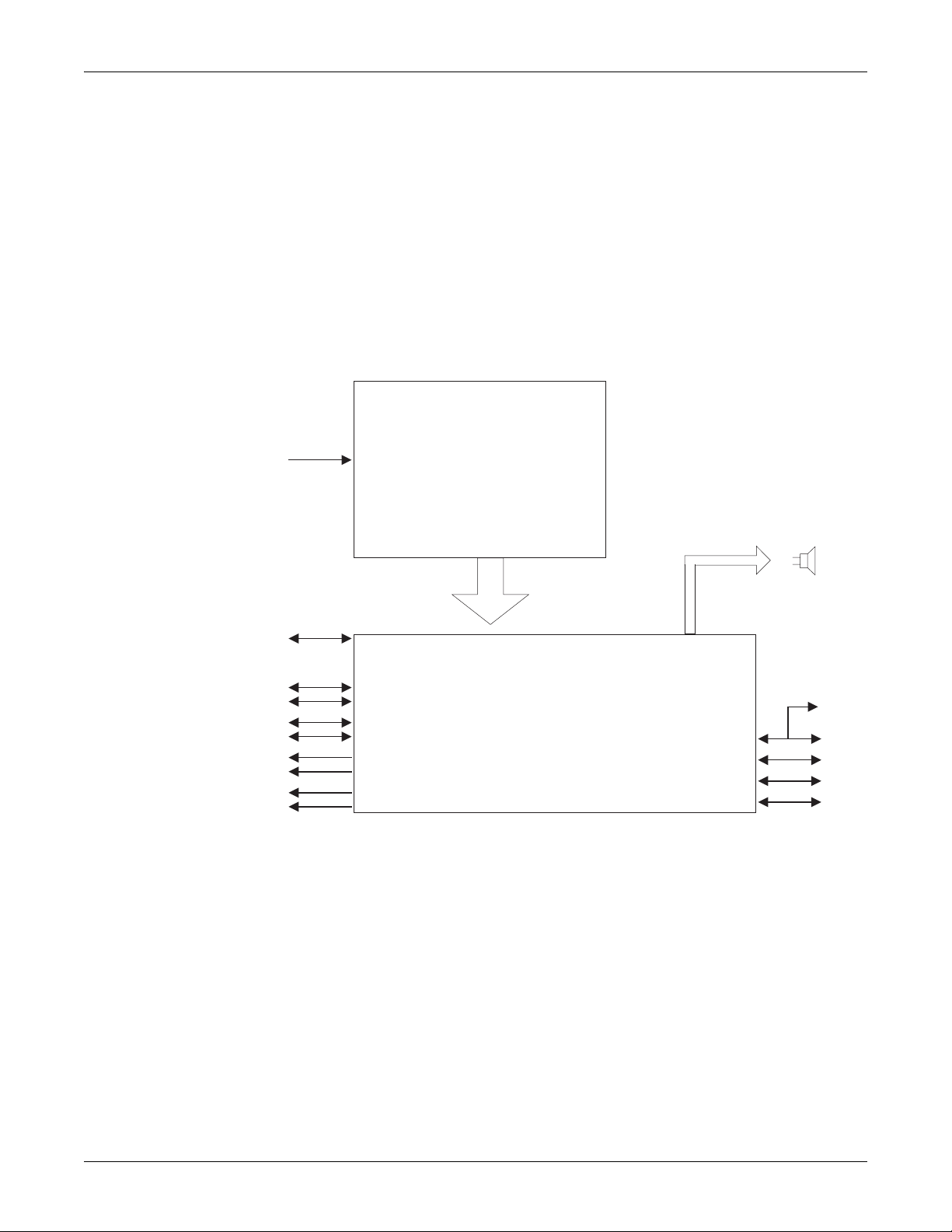
Theory of operation
The Solar 8000M/i patient monitor consists of a processor board, a power
supply board, and a speaker. Software running on the processor board
processes incoming data, services the communication channels and
performs the general functions. System software may be updated using a
laptop computer connected to the Solar 8000M/i processing unit or the
Unity Network or from a Clinical Information Center (CIC) on the Unity
Network.
The following theory of operation provides an overview of the various
functional circuit boards in the monitor.
AC Power
Ethernet
TRAM-NET 1
TRAM-NET 2/ePort*
Serial Port 1
Serial Port 2
DFP 1
DFP 2
VGA 1
VGA 2
*ePort available on 801586-003 only.
Power Supply
Power
harness
Processor Board
Speak
Keypa
M-Por
M-Por
M-Por
M-Por
034B
2026265-075C Solar 8000M/i patient monitor 2-13
Page 30
Equipment overview: Theory of operation
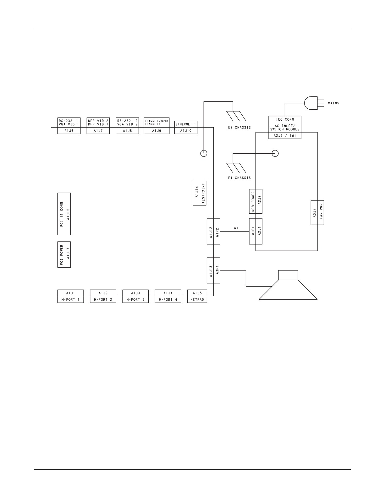
Block diagram of internal connections
Power Supply
Assembly
Processor
Board
Speaker
036B
2-14 Solar 8000M/i patient monitor 2026265-075C
Page 31

Processor board
Equipment overview: Theory of operation
The processor board processes acquired data for the generation of
displayed information, audible alarms, and supports communication
channels for the acquisition system, serial peripherals and the Unity
Network.
035B
2026265-075C Solar 8000M/i patient monitor 2-15
Page 32

Core processing system
Equipment overview: Theory of operation
The core processing system of the processor board is the microprocessor,
the memory subsystem and the peripheral set.
The microprocessor
The Motorola PowerPC MPC860P, operating internally at 66.66 MHz
and 33.33 MHz externally, is the microprocessor used in the Solar
8000M/i processor PCB. The MPC860P consists of a PowerPC core with a
System Interface Unit (SIU) and Communications Processor Module
(CPM).
The main facilities integrated into the MPC860P include:
PowerPC Core including:
16k of Dual ported RAM for registers and microcode
A Memory Management Unit (MMU)
16 kByte Instruction Cache
8 kByte Data Cache
System Integration Unit (SIU) including:
Memory Controller and Wait State Generator via Eight(8)
General Purpose Chip-Select Machines (GPCM) and two(2)
Universal Programmable Machines (UPM)
Development Port/Background Debug Monitor
System Configuration and Protections such as the Bus Monitor,
Software Watchdog Timer, and Periodic Interrupt Timer
PLL Clock synthesizer
Communication Processor Module (CPM) including:
One (1) Fast Ethernet Channel (Media Independent Interface)
Four SCCs, all of which can do IEEE 802.3 Ethernet
Two SMCs (UARTs)
One SPI Interface
One I2C Interface
Seven IRQ lines
I/O port pin banks, some of which can be programmed to
generate an interrupt when a condition is present
A Development Port, commonly referred to as a Background Debug
Monitor (BDM) debug port on other processors, is resident in the
MPC860 to assist in debugging and troubleshooting the processor
operation.
NOTE
The MPC860 is +5V I/O tolerant on all of its pins except for the clock
input. This is important because the signals from the TRAM-NET
Hub are +5V signal levels.
2-16 Solar 8000M/i patient monitor 2026265-075C
Page 33

Equipment overview: Theory of operation
Memory subsystem
The processor PCB provides the memory resources necessary for code
storage and execution, and nonvolatile and configuration data storage by
providing the following:
FLASH Memory for Boot Code, Main Code and Parametric (TMSS)
Storage Memory,
DRAM Memory for Code Execution and Volatile Data Storage, and,
SRAM Memory that is battery backed for Nonvolatile Data Storage.
EEPROM Memory for network configuration data.
The memory subsystem utilizes the memory controller facility of the
MPC860. This allows for the addresses, strobe generation and wait
stating to be under software control.
Peripheral set
Clock Source – The central clock source for the processor PCB is a
crystal oscillator with a frequency of 14.7456 MHz.
Power monitor, watchdog and battery switch – The MAX793
provides the following facilities:
Power-on reset
Battery switchover
Battery charge level indication (battery OK)
Power going away indication (Low Line)
SRAM chip select gating
Manual reset input
Watchdog facility
Real time clock – The Epson RTC-8593AA is the Real Time Clock
(RTC) used. It is an I2C RTC with an internal crystal and can operate
with a supply voltage of +3.3V. The storage of the year will have to be
done in another location since this RTC has only 2 bits for storage of the
year. The RTC must be battery backed to insure that the time is
continued to be kept during power down periods. The I2C address for the
RTC is “1011xxxx”.
Serial EEPROM – The serial EEPROM used is a Xicor X24165. The
X24165 is a 16k bit part organized as 2k x 8, I2C compatible and a +3.3V
part. The data stored in the EEPROM would be the Ethernet Address, IP
Address, Software level, product type, year and Power-Applied
Indication. The I2C address for the EEPROM is “1010001x”.
NOTE
The serial EEPROM on the Solar 8000M/i processor PCB is not
removable.
Audio tone generation and output amplifier – The Solar 8000M/i
processor PCB provides audio output for alarm and parameter tones.
2026265-075C Solar 8000M/i patient monitor 2-17
Page 34

Video system
Equipment overview: Theory of operation
FPGA logic chip – The Processor PCB has one (1) Field Programmable
Gate Array logic chip on the board to provide the PCI host bridge
interface, the TRAM-NET strobe processing, the M-port support and a
revision port. The FPGA used is an Altera 6016 FLEX FPGA. The FPGA
is configured at power up by the Boot Code startup software loading the
FPGA configuring data into the FPGA. Therefore the FPGA does not
contain any functionality that is needed to allow the MPC860 to access
and execute Boot Code or any other necessary facilities needed to get the
processor PCB initialized at startup. In addition, any signal lines that
the FPGA drives must be able to accommodate the fact that at power up
the FPGA lines are high impedance until the FPGA is programmed.
NOTE
The FPGA must be 5V I/O tolerant since it is interfacing the older
+5V technology parts such as the TRAM-NET Hub.
The video system consists of one video accelerator and two duplicate sets
of CRT and flat panel buffers. A maximum of two analog and two digital
flat panel displays can be used.
A 65.00 MHz clock oscillator is used to drive the video system. The
MPC860 accesses the video systems over the PCI Bus using the Host
Bridge implementation within the FPGA.
Video system components
The video system has a video graphics chip, some discretes and
connectors for VGA (RGB) and DFP (Digital Flat Panel) video displays as
well as a RS-232 serial port to provide for a Touchscreen input.
Video graphics chip – The video graphics accelerator chip has the
following facilities:
4 Mbytes of internal memory
A bandwidth of 800 Mbytes/second minimum
RAMDAC for direct VGA/RGB output
Flat Panel Drive (using SiI164 components)
Programmable Ports Pins
VGA video output – The RGB output from the graphics accelerator is
used to generate the video signals output on the 15 pin VGA video
connectors.
DFP video output – Flat Panel drive signals from the video accelerator
are interfaced to a Silicon Image SiI164’s.The SiI164’s convert signals to
transition Minimized Differential Signaling (TMDS) levels before
connection to the 20 pin MDR DFP connectors.
RS-232 serial ports
The RS-232 serial ports provide the interface to the iPanel computer
(RS-232 1) and serial communication devices such as a touchscreen
display. See the Communication System for detailed discussion.
2-18 Solar 8000M/i patient monitor 2026265-075C
Page 35

Communication system
Equipment overview: Theory of operation
PCI bus implementation
The PCI Bus is used to communicate with the video accelerator and two
(2) expansion slots. The PCI Bus is a 32 bit, 33MHz implementation. The
PCI Bus interface to the MPC860 Bus was accomplished by
implementing a purchased Intellectual Property (IP) design in the FPGA
for a Host Bridge and PCI Bus Arbiter.
Ethernet for unity
The Processor PCB provides one (1) IEEE 802.3 10BaseT compliant
Ethernet port. This port is implemented using an SCC within the
MPC860 and an LXT905 Serial Interface Adapter. An Ethernet Port
Address label is affixed to the connector bracket and visible to the user
without disassembly.
Processor SCC channel – The first Serial Communication Controller
(SCC) is used to implement the Ethernet channel.
Serial interface adapter – The LXT905 is used as the Serial Interface
Adapter (SIA) for each Ethernet channel.
TRAM-NET (2 ports)
The Processor PCB provides an interface to the GEHC proprietary
Carrier Sense Multiple Access/Collision Detection (CSMA/CD) network,
TRAM-NET, by providing a TRAM-NET Controller (TNC) and a Hub
facility. The TRAM-NET 1 port provides TRAM-NET communication
only for connection to the Tram-rac 4A or Tram-rac 2. The TRAM-NET
2/ePort port provides TRAM-NET communication or ePort
communication for connection to the PDM with an ePort cable. When the
TRAM-NET 2/ePort connector is connected to PDM, the connection
uses ethernet through the Broadcom ethernet switch.
Processor SCC channel – The MPC860 fourth Serial Communication
Controller (SCC) is used to implement the TRAM-NET Controller. This
is done by operating the SCC in transparent mode and using software to
provide the functionality that was originally provided by an external
communications processor.
Hub – The Hub chip is the Solar 9000 FPGA implementation. It
accommodates the TNC port as well as four (4) external ports functioning
as a “Header Hub”. The Header Hub “turns the signal around” by
sending the “Up” signal out on the “down” path, generates the carrier
sense signal so that the TNC will not cause an “out of window” collision,
generates Collision Presence signals at the detection of a collision, and
retimes the bits.
NOTE
The signals out of the Hub are at +5V signal levels, so any +3.3V
devices interfacing to the Hub must be +5V tolerant.
Drivers and receivers – The DS8923 Dual Differential Driver/Receiver
pair is used to convert the signals between the TRAM-NET differential
RS-422 level and TTL levels.
2026265-075C Solar 8000M/i patient monitor 2-19
Page 36

Equipment overview: Theory of operation
Isolation – The TRAM-NET signals are electrically isolated with signal
transformers. The TRAM-NET power source is not isolated before being
delivered to the TRAM-NET network.
ESD protection scheme – The typical diode/transzorb pair is employed
to clamp the TRAM-NET connector pins to the common return plane.
Since the TRAM-NET is really not an electrically isolated network, the
need for maintaining isolation in the ESD protection scheme is not
present.
M-Ports (4)
ID signal – The ID Signal is generated using a Dallas Semiconductor 1Wire Line Driver chip, DS2480. The DS2480 is interfaced by the
MPC860's SCC3, which is multiplexed in the FPGA across the four (4) MPorts. The benefit of the DS2480 is that it relieves the MPC860 of doing
most of the timing for the interface to the 1-Wire memory device, such as
the DS2430 out in the DIDCA device. Also it improves noise immunity by
reading at the latest possible time and it minimizes emissions by driving
the line with a controlled edge rate and controlled drive current. The rate
at which the DS2480 can receive new commands or transfer additional
bytes of data is synchronized by the MPC860 waiting for a received
character interrupt response from the DS2480 before it can load the next
character. The ID signal has its own Return line. The ID Signal and its
Return share the RJ-45 connector pins that the M-Port Ethernet 10 Base
T Transmit differential pair uses. The functionality of the shared
connector pins is determined by a relay under software control.
RS-232/UART interface – The M-Port RS-232 interface is provided by
a Philips SC28L194 Quad UART (one UART per M-Port) and an Analog
Devices ADM202E RS-232 Driver/Receiver. The SC28L194 Quad UART
has sixteen (16) byte FIFO's on both the receiver and transmitter and I/O
port pins that function as status LED drive signals. The benefit of the
FIFOing is to reduce the overhead to the MPC860 to service the UART's.
The Quad UART uses the auto vectored interrupt on level 3.
Ethernet facility – A Broadcom Ethernet Switch provides each M-Port
with Ethernet capability. With the relay in the Ethernet position, pins 3
and 6 in the RJ-45 connector provide the Ethernet Differential Transmit
pair. The Ethernet receive pair are provided on pins 1 and 2 of the RJ-45
connector.
NOTE
The M-Port provides Host or Hub pinouts, not device side pin outs, so
that a one-to-one Category 5 cable can be used to connect any
Ethernet device up using an M-Port.
2-20 Solar 8000M/i patient monitor 2026265-075C
Page 37

Equipment overview: Theory of operation
The Serial Management Interface (SMI) to the Broadcom Ethernet
Switch is provided by reprogramming SCC3 in the MPC860 to be an
HDLC controller and setting the appropriate MPC860 port pins to get
the proper muxing action within the FPGA. The use of the SMI is to
determine which M-Ports have a functioning 10BaseT Ethernet
connection on them without having to switch the relay back to ID mode
and interrogate for a One-Wire interface.
NOTE
The clock source for the SMI is selected by the MPC860 to be either
sourced by itself or by the Broadcom Ethernet Switch under software
control.
M-Port power sourcing – Each M-Port is capable of providing
+5V +/- 5% @ 100mA into an external load.
Isolation – Per the M-Port Specification, Basic Insulation for 250Vac is
provided between each M-Port and any other isolated facility and from
earth ground.
ESD protection scheme – The M-Port connectors are ESD protected
by using the planar capacitance method since they are isolated from an
earth connection. The typical diode/transzorb pair is employed to clamp
the connector pin to its isolated return plane. The impedance of the
connector contact, the ferrite bead and the copper traces form an
impedance divider with the 'planar' capacitor formed by the dielectric
material in the PCB layer between the copper of the isolated return
plane and the copper of the common (earthed) plane. The expectation is
that the physical impedance divider formed by the bead/trace/connector
inductance and the planar capacitor will accomplish the following two
results:
Limit the rate of rise of the voltage across the isolation barrier, i.e.,
across the planar capacitor, and
Limit the peak amplitude to which the voltage across the barrier
rises to.
RS-232 serial ports
Both RS-232 serial ports are associated to a video set as described earlier
to accommodate a touchscreen. However, the serial ports are not limited
to being a touchscreen interface only. The RS-232 1 port also interfaces
to the iPanel computer and either of these serial ports are capable of
providing a polled data service facility or can be used as a service port.
Processor SMC channels – The RS-232 1 uses the SMC1 and the RS232 2 will use SMC2 in the MPC860.
Isolation – The serial ports are not isolated with respect to earth
ground.
ESD protection scheme – The typical diode/transzorb pair is employed
to clamp the RS-232 serial port connector pins to the common return
plane. Since the serial ports are not electrically isolated, the need for
maintaining isolation in the ESD protection scheme is not present.
2026265-075C Solar 8000M/i patient monitor 2-21
Page 38

Power supply
Speaker
Equipment overview: Theory of operation
I2C bus
The I2C bus is used to interface to the Real Time Clock and the Serial
EEPROM.
SPI interface
The SPI is used to program the FPGA.
The power supply generates DC voltages necessary to power the
processor board and the communication channels (M-ports and devices
connected to TRAM-NET). It consists of a mains (AC line) PWM
converter, that creates a 16.75 output voltage bus from which two
outputs are developed. The main 16.75V output also provides external
power to the RAC, data acquisition modules, and plug-in modules.
The speaker generates sound for alarms, QRS detection, and SpO2 pulse
tones.
2-22 Solar 8000M/i patient monitor 2026265-075C
Page 39

3 Installation
2026265-075C Solar 8000M/i patient monitor 3-1
Page 40

Installation: Back panel connections
Back panel connections
Connect the power cord to the power supply inlet on the back of the Solar
8000M/i patient monitor. If using a Tram-rac with power supply, connect
the power cord as shown.
007A
Power switch
Ethernet connector RS-232 connectorsPower switch
Voltage select
Ethernet connector RS-232 connectors
TRAM-NET connectors Video connectorsPower cord
008C
Digital flat panel
connectors
Solar 8000M
Power cord Voltage select TRAM-NET/ePort connectors
Solar 8000i
Video connectors Digital flat panel
connectors
010C
NOTE
The number of video connectors varies by configuration.
3-2 Solar 8000M/i patient monitor 2026265-075C
Page 41

TRAM-NET
Installation: Back panel connections
CAUTION
Equipment damage. Connect all peripheral equipment
before plugging the power cord into an AC outlet.
Otherwise, connectors may be damaged.
TRAM-NET provides the network for communication with bedside
peripherals and acquisition modules.
NOTE
If two Tram-racs are connected in any configuration, one must have a
power supply.
The following devices connect to either of the two TRAM-NET ports on
the Solar 8000M/i monitor. The connector is a 9-pin, D-type.
Tram-rac 4a housing with or without power supply
Tram-rac 2 housing
Tram-rac 4 housing with or without power supply
Tram-rac 3 housing with or without power supply
Patient Data Module (PDM) connects to TRAM-NET 2/ePort
connector only.
Tram-rac 4a housing
Tram-rac 2 housing
009C
011A
2026265-075C Solar 8000M/i patient monitor 3-3
Page 42

Installation: Back panel connections
Tram-rac 4a housings with and without power supply
CAUTION
Equipment damage. Connect the Tram-rac housing to the
Solar 8000M/i patient monitor before plugging the power
cord into an AC outlet. Connecting these devices to a
powered Solar 8000M/i patient monitor could damage
connectors.
One Tram-rac must have a
power supply.
013C
Patient Data Module
The Patient Data Module (PDM) is an acquisition device that connects to
the Solar 8000i patient monitor via the ePort cable.
940B
Connect one end of the ePort cable to the TRAM-NET2/ePort connector
and the other end to the Patient Data Module.
3-4 Solar 8000M/i patient monitor 2026265-075C
Page 43

ETHERNET
Installation: Back panel connections
One Tram-rac must have a
power supply.
043B
The ETHERNET connector provides an ANSI/IEEE 802.3 10BaseT
Ethernet standard interface to the Unity Network using a Category 5
network cable. The connector is an 8-pin, RJ-45 type.
VGA VID 1 and 2
NOTE
The number of video connectors varies by configuration.
The two VGA connectors provide an interface to analog (VGA) displays.
The connector is a 15-pin, high density D type.
WARNING
Do not connect a monochrome display to the Solar
8000M/i patient monitor. Visual alarm indictors may not
appear properly, resulting in a hazard to the patient.
014D
2026265-075C Solar 8000M/i patient monitor 3-5
Page 44

DFP VID 1 and 2
Installation: Back panel connections
Two DFP (Digital Flat Panel) connectors provide an interface to digital
displays. The connector is a 20-pin, MDR type.
014C
RS-232 1
RS-232 2
The RS-232 1 serial connector provides an interface to the iPanel
computer. If not using an iPanel, it interfaces to a PC for software
upgrades or polled-parameter service. The connector is a 9-pin, D type.
The RS-232 2 serial connector provides a touchscreen interface. The
connector is a 9-pin, D type.
NOTE
Use cable 2006733-00X for touchscreen connection. The cable
supplied with the display will not work.
3-6 Solar 8000M/i patient monitor 2026265-075C
Page 45

Installation: Front panel connectors and indicators
Front panel connectors and indicators
The front panel connectors consist of four M-Ports. The Solar 8000M also
has a keypad connector. Each port has a LED indicator.
M-Port LED indicators Power LED indicator
M-Ports
M-Port connectors
015A
Solar 8000i
015B
Solar 8000M
Keypad connector
M-Port means multi-protocol and supports Ethernet 10BaseT, RS-232, 1
wire identification, and is MIB (Medical Information Bus) compliant.
M-Ports support AutoPort devices, but an AutoPort to M-Port adapter,
PN 2001973-001, is required. The adapter must connect to the AutoPort
device, not the M-Port host (the Solar 8000M/i patient monitor).
The following devices connect directly to the M-Ports. The connector is an
8-pin RJ-45 type.
Solar 8000M/i remote control
Solar 8000M/i keypad
PRN 50-M digital writer
RM-M respiratory mechanics module
Remote Alarm Terminal (Nurse Call and Alarm Light System)
Laser printer (requires a serial port on the printer and an interface
adapter to connect to the monitor)
Unity Network ID connectivity device
2026265-075C Solar 8000M/i patient monitor 3-7
Page 46

Remote control or keypad
Installation: Front panel connectors and indicators
The following devices connect to M-Port hosts using AutoPort to M-Port
adapter PN 2001973-001.
PRN-50 digital writer with AutoPort
Respiratory mechanics module with AutoPort
NOTE
AutoPort to M-Port adapter PN 2001973-001 is required for
connecting AutoPort devices to M-Ports. Plug the adapter end
labeled AutoPort into the AutoPort device.
The remote control or keypad is DIDCA programmed for specific care
areas (adult, neonatal, or operating room). A keypad holster mount is
available for mounting under the display.
NOTE
The Solar 8000M/i requires an interface (remote control or keypad)
with all display types.
NOTE
The error message WARNING: REMOTE MISMATCHED WITH
MONITORING MODE displays if a mismatched keypad/remote
control is connected to the Solar 8000M/i patient monitor.
PRN-50 digital writer and respiratory mechanics module
The figure below shows the PRN-50-M digital writer connected to one of
the M-Ports. The RM-M respiratory mechanics module has similar
connections.
AutoPort or M-Port connector.
Note: If this is a PRN 50 or RM module with
AutoPort, then adapter PN 2001973-001 is
required.
016A
3-8 Solar 8000M/i patient monitor 2026265-075C
Page 47

Installation: Front panel connectors and indicators
Unity Network ID connectivity device
The figure below shows the Unity Network ID connectivity device
connected to one of the M-Ports.
NOTE
This connection requires that the Unity Network ID connectivity
device IP address is a 10.X.X.X address. Refer to the Unity Network
ID connectivity device service manual for more details.
Ethernet connector
Laser printer
017A
Refer to the instructions provided in Laser Printer Support Kit, pn
2013421-001, for details on interconnection using the interface adapter
and installing a serial card in a laser printer.
WARNING
SHOCK HAZARD. Laser printers are UL 60950/EN
60950 certified equipment, which may not meet the
leakage current requirements of patient care equipment.
This equipment must not be located in the patient
vicinity unless the medical system standard EN
60601-1-1 is followed.
Do not connect a laser printer to a multiple portable
socket outlet (MPSO) supplying patient care equipment.
The use of an MPSO for a system will result in an
enclosure leakage current equal to the sum of all the
individual earth leakage currents of the system if there is
an interruption of the MPSO protective earth conductor.
2026265-075C Solar 8000M/i patient monitor 3-9
Page 48

Indicators
Power up
Installation: Power up
A green LED indicates that the unit is connected to an AC power source
and the power switch is turned on. There is a green/yellow LED above
each M-Port indicating the M-Port status.
Solid green indicates the device is communicating properly.
Slow flashing yellow indicates the device has been identified, but
there is no communication.
Quick flashing yellow indicates that too many identical devices are
connected or the device cannot be identified.
Refer to Chapter 5, “Troubleshooting” if an LED is not green.
NOTE
Check power voltage at your location and set power to either 120 V or
240V.
After making all connections, plug the power cord into an AC wall outlet,
turn the power switch to 1 (on), and turn on the display. The power LED
illuminates and after about 10 seconds a display appears.
If the Solar 8000M/i patient monitor does not work properly, refer to
Chapter 5, “Troubleshooting” .
3-10 Solar 8000M/i patient monitor 2026265-075C
Page 49

Installation: TRAM-NET communication
TRAM-NET communication
Overview
The Solar patient monitor uses two distinct local area networks:
TRAM-NET communication, and
Ethernet communication.
Consider TRAM-NET as a small area network (SAN) contained in one
room or at the patient bedside. Consider Ethernet as the local area
network (LAN) for room-to-room communication or communication
between patient monitors, central stations, and other GE equipment
throughout the hospital.
NOTE
GE highly recommends using a ‘private’ LAN to connect Unity
products. The purpose of the Unity Network is to connect only Unity
devices for the exchange of patient data and room-to-room
communication. Adding non-Unity devices (PCs, laptops, desktops,
etc.) may compromise the ability of the Unity Network to meet its
intended use.
Internal hub
A ‘private’ LAN is not the same as a private IP address.
This local area network links all patient monitors, central stations, and
other GE equipment throughout the hospital.
The TRAM-NET connector makes a TRAM-NET small area network
available for the peripheral devices. The TRAM-NET controller resides
within the main processor which provides efficient data transfer by
sharing main memory.
TRAM-NET is a small network that offers ample flexibility, a high rate
of communication, and relatively inexpensive cabling. Data is
transmitted at the rate of 921.6K bits per second. It uses a star topology,
sometimes referred to as a rooted tree topology. This means that the
wiring of the network can be pictured as a star or a series of stars. The
center of each star is called a hub, and the points of the star are called
nodes. There are cables between the nodes and the hubs, but no cables
exist between nodes.
Data is acquired at a node, and is transmitted through a hub to all the
other nodes. Each node has an address so data will be received by the
node with the correct destination address. It is impossible for a node to
communicate with another node without the data going through a hub
somewhere along its journey. The hub controls all of the data ‘traffic’ in
the system.
In a TRAM-NET system, the head hub is contained in the patient
monitor, but there will be intermediate hubs in the Tram-rac housing
and Tram module as well.
2026265-075C Solar 8000M/i patient monitor 3-11
Page 50

Installation: Ethernet communication
Ethernet communication
About ethernet
The GE Unity Network uses Ethernet for device-to-device
communications. This local area network links all patient monitors,
clinical information centers, and other GE equipment throughout the
hospital. Depending on the construction of the hospital, thick-net, thinnet, or CAT-5 twisted pair cabling is used. The Solar 8000M/i is designed
to be used with twisted-pair cabling. Consult GE when trying to interface
with either thick-net or thin-net cabling. The real-time GE Unity
Network operates at 10 Mbps, half-duplex.
Twisted pair
Twisted pair is the most popular cabling because it is easy to install and
flexible to work with. It uses the star topology with a switch as the hub of
the segment. A maximum of 100 meters or 328 feet is the longest length
of twisted pair cable allowed. The maximum number of devices on the GE
Unity Network is 1,000.
CIC Pro
CIC Pro
Solar 8000M/i
Printer
Segment
Solar 8000M/i
Switches
1 to n
041A
3-12 Solar 8000M/i patient monitor 2026265-075C
Page 51

Network terms
Node
MAC address
Switch
Installation: Ethernet communication
Each network device or node is assigned a MAC address number and
requires a network connection to interface between the network device
and the network.
A 48-bit address assigned by the manufacturer to uniquely identify a
node of the network. This is also known as the Ethernet address.
To implement the star topology, each network device is connected to a
network switch. The switch passes all network data between each
network device in the star segment. Typically, the switch supports 12 to
48 network devices and may be linked to other switches to form larger
networks.
Segment
IP address
Subnet
A network segment is comprised of all devices connected to 1 or many
switches which are in-turn connected together to form a larger network.
The boundaries of the segment are defined by networking equipment
that regulate the flow of packets into and out of the segment (e.g. routers
and switches).
A 32-bit (IPv4) address assigned by the user (either statically or
dynamically from a server) to uniquely identify the packets from a device
for routing purposes.
A subnet is a logical segment of a larger network that shares a common
IP address range as defined by a subnet mask. Proper subnetting can
improve the performance and security of a network. Solar 8000 series
monitors support classful subnetting.
2026265-075C Solar 8000M/i patient monitor 3-13
Page 52

Installation: Ethernet communication
3-14 Solar 8000M/i patient monitor 2026265-075C
Page 53

4 Maintenance and
checkout
2026265-075C Solar 8000M/i patient monitor 4-1
Page 54

Maintenance and checkout: Maintenance schedule
Maintenance schedule
Manufacturer recommendations
To help ensure the equipment remains in proper operational and
functional order, adhere to a good maintenance schedule. The
manufacturer recommends that the following be performed by service
personnel upon receipt of the equipment, every 12 months thereafter,
and each time the unit is serviced:
Visual Inspection
Cleaning
Electrical Safety Tests
Checkout Procedure
Clearing the Stored Patient Data Memory: Admit and discharge a
test patient every 12 months to clear the monitor’s stored patient
data memory.
Manufacturer responsibility
Preventive maintenance
The message “EC1” will appear on the monitor to the left of the ECG
parameter block after 395 days of operation. This message is a reminder
that it is time to perform preventive maintenance procedures on the
monitor. Perform all of the maintenance procedures listed under
“Manufacturer Recommendations” above.
WARNING
Failure on the part of all responsible individuals,
hospitals or institutions, employing the use of this device,
to implement the recommended maintenance schedule
may cause equipment failure and possible health
hazards. The manufacturer does not, in any manner,
assume the responsibility for performing the
recommended maintenance schedule, unless an
Equipment Maintenance Agreement exists. The sole
responsibility rests with the individuals, hospitals, or
institutions utilizing the device.
4-2 Solar 8000M/i patient monitor 2026265-075C
Page 55

Visual inspection
Maintenance and checkout: Visual inspection
The Solar 8000M/i patient monitor and its components should be
carefully inspected prior to installation, once every 12 months thereafter,
and each time the equipment is serviced.
Carefully inspect the equipment for physical damage to the case, the
display screen, and the keypad. Do not use the monitor if damage is
determined. Refer damaged equipment to qualified service
personnel.
Inspect all external connections for loose connectors or frayed cables.
Have any damaged connectors or cables replaced by qualified service
personnel.
Inspect the display face for marks, scratches, or other damage.
Physical damage to a CRT display face may pose an implosion
hazard. Have the CRT replaced by qualified service personnel if
necessary.
2026265-075C Solar 8000M/i patient monitor 4-3
Page 56

Cleaning
Cleaning precautions
Maintenance and checkout: Cleaning
NOTE
See “Cleaning, disinfecting and storing GE ECG cables and
leadwires” on page 4-5 for instructions specific to GE ECG cables and
leadwires.
Use one of the following approved solutions:
Cidex solution
Sodium hypochlorite bleach (diluted)
Mild soap (diluted)
Lint-free cloth
Dust remover (compressed air)
To avoid damage to the equipment surfaces, never use the following
cleaning agents:
organic solvents,
ammonia based solutions,
acetone solution,
alcohol based cleaning agents,
Betadine solution,
a wax containing a cleaning substance, or
abrasive cleaning agents.
Exterior cleaning
Cleaning the display
Clean the exterior surfaces with a clean, lint-free cloth and one of the
cleaning solutions listed in the table above.
Wring the excess solution from the cloth. Do not drip any liquid into
open vents, switches, plugs, or connectors.
Dry the surfaces with a clean cloth or paper towel.
To clean the display, follow the recommendations of the display’s
manufacturer. In general you will need to use a soft, clean, lint-free cloth
dampened with a glass cleaner.
CAUTION
To avoid getting liquid into connector openings, do not
spray glass cleaning or general cleaning solutions
directly onto the product’s surface.
4-4 Solar 8000M/i patient monitor 2026265-075C
Page 57

Maintenance and checkout: Cleaning
Cleaning the Touch Screen Display
1. Turn OFF the mains power switch on the monitor and disconnect it
from the power source.
2. Clean the screen with an ammonia free glass cleaner and lint free
cloth.
CAUTION
Do not spray any glass cleaning solution or any general
cleaning solutions directly onto the monitor’s display
surface. Always dampen the towel and then clean the
screen.
Cleaning, disinfecting and storing GE ECG cables and leadwires
NOTE
These instructions supersede all cleaning/disinfecting instructions
for GE ECG Cables and Leadwires. All safety statements and notes
in the manual still apply.
Cleaning or disinfecting
1. Remove cables and leadwires from the handheld device or system
before cleaning.
2. Use care in cleaning leadwires to prevent pulling the long wires from
the connector ends. Metal connections can be pulled away from the
connectors.
3. For general cleaning of cables and leadwires, wipe using a lightly
moistened cloth with a mild soap and water solution. Then wipe and
air dry.
4. For disinfecting the cables and leadwires, wipe exterior with a soft
lint-free cloth, using the following solution as recommended in the
APIC Guidelines for Selection and Use of Disinfectants (1996):
Sodium hypochlorite (5.2% household bleach) minimum 1:500
dilution (minimum 100 ppm free chlorine) and maximum 1:10
dilution.
Any sodium hypochlorite wipe product that meets the above
guidelines of can be used.
NOTE
Wring excess disinfectant from wipe before using.
NOTE
Any contact of disinfectant solutions with metal parts may cause
corrosion.
5. Do not immerse either end of a cable or leadwire connector.
Immersing or “soaking” the connector ends may corrode metal
contact ends and affect signal quality.
6. Wipe off cleaning solutions with a clean, lightly moistened cloth.
2026265-075C Solar 8000M/i patient monitor 4-5
Page 58

Sterilization
Maintenance and checkout: Cleaning
7. Dry thoroughly with a dry lint-free cloth and let air dry for at least
30 minutes.
NOTE
Drying times may vary based on the environmental conditions.
8. Take care not to let fluid “pool” around connection pins. If this should
happen, blot dry with a soft, lint-free cloth.
9. Do not use excessive drying techniques, such as oven, forced heat or
sun drying.
NOTE
EtO sterilization is not recommended, but may be required for cables
and leadwires. Frequent sterilization will reduce the useful life of
cables and leadwires.
Sterilize with ethylene oxide gas (EtO) at a maximum temperature of 50°
C/122° F. After EtO sterilization, follow the recommendations from the
sterilizer manufacturer for required aeration.
Cautions
Storage
Never immerse the handheld device, cables, or leadwires in any
liquid.
Do not pour or spray any liquid directly on cables or leadwires or
permit fluid to seep into connections or openings.
Never use conductive solutions, solutions that contain chlorides, wax,
or wax compounds to clean handheld devices, cables or leadwires.
Never use solutions or products that contain the following:
Any type of Ammonium Chloride such as, but not limited to:
Dimethyl Benzyl Ammonium Chloride
Quaternary Ammonium Chloride solutions
Abrasive cleaners or solvents of any kind
Acetone
Ketone
Betadine
Alcohol-based cleaning agents
Sodium salts
Never autoclave or steam clean cables or leadwires.
Store in a dry well-ventilated area.
Vertically hang cables and leadwires.
Do not coil leadwires or cables tightly around any medical device.
4-6 Solar 8000M/i patient monitor 2026265-075C
Page 59

Maintenance and checkout: Cleaning
Improper cleaning products and processes impact/results
Product discoloration.
Metal part corrosion.
Brittle wires.
Brittle and breaking connectors.
Reduced cables and leadwires life.
Unit malfunction.
Void warranty.
Cleaning products to avoid
Cleaning products known to cause the types of problems listed above
include, but are not limited to:
Sani-Cloth
Ascepti
HB Quat
Clorox
Over-the-counter detergents (e.g. Fantastic
®
Wipes
®
Wipes
®
Wipes (they do not contain bleach).
®
, Tilex®, etc.).
Products that contain active ingredients and solutions similar to these
products should also be avoided.
NOTE
For additional information, refer to the How to Reach Us page of the
manual for contact information. Also see the GE Handheld Medical
Devices Cleaning, Disinfecting, and Storage addendum.
2026265-075C Solar 8000M/i patient monitor 4-7
Page 60

Maintenance and checkout: Electrical safety tests
Electrical safety tests
Recommendations
Electrical safety tests provide a method of determining if potential
electrical health hazards to the patient or operator of the device exist.
GE recommends that all safety tests be performed
upon receipt of the device,
once a year thereafter,
after any upgrade,
any time the main enclosure is disassembled, or a part is repaired or
replaced.
Record the date and results on the Repair Log included at the end of this
chapter.
These instructions are intended for every component in the system. If the
system includes a Tram-rac housing without its own power supply, it
should remain connected to the monitor throughout the safety tests.
Test conditions
WARNING
Failure to implement a satisfactory maintenance
schedule may cause undue equipment failure and
possible health hazards. Unless you have an Equipment
Maintenance Contract, GE does not in any manner
assume the responsibility for performing the
recommended maintenance procedures. The sole
responsibility rests with the individual or institution
using the equipment. GE service personnel may, at their
discretion, follow the procedures provided in this manual
as a guide during visits to the equipment site.
Perform electrical safety tests under normal ambient conditions of
temperature, humidity, and pressure.
4-8 Solar 8000M/i patient monitor 2026265-075C
Page 61

Test equipment
Maintenance and checkout: Electrical safety tests
The recommended test equipment required to perform electrical safety
tests is listed below.
Item Specification
Leakage Current Tester Equivalent to the circuits shown
Digital Multimeter (DMM) AC volts, ohms
Ground Bond Tester 0 – 1 ohm
ECG Test Body All leads together
Masimo SET SpO2 Test Body 2006036-001
Host patient monitor system Solar 8000M or Solar 8000i
Acquisition device Tram-rac with TRAM module or Patient
Data Module
Set up
Prepare the Solar 8000M or Solar 8000i patient monitor and the acquisition device
for electrical safety tests.
1. Confirm that all components of the monitoring system are correctly
2. Verify that the power indicator illuminates on the acquisition device.
Power outlet test
Verify that the power outlet is wired correctly per the country’s electrical
code standard before starting the following electrical safety tests. The
results of the following tests will be inaccurate unless a properly wired
power outlet is used.
Ground (earth) integrity
Listed below are two methods for checking the ground (earth) integrity,
“Ground Continuity Test” and “Impedance of Protective Earth
Connection.” These tests determine whether the device's exposed metal
and power inlet's earth (ground) connection have a power ground fault
condition.
connected as described in Chapter 3, “Installation” .
Perform the test method below that is required by your country/local
governing safety organization.
2026265-075C Solar 8000M/i patient monitor 4-9
Page 62

Maintenance and checkout: Electrical safety tests
Ground continuity test
1. Disconnect the device under test from the power outlet.
2. Connect the negative (–) lead of the DMM to the protective earth
terminal (ground pin in power inlet connector) or the protective earth
pin in the mains plug (ground pin in power cord).
3. Set the DMM to the milliohm (mΩ) range.
4. Connect the positive (+) lead of the DMM to all exposed metal
surfaces on the device under test.
5. Resistance must read:
0.1 ohm or less without power cord
0.2 ohms or less with power cord
Impedance of protective earth connection
This test stresses the ground system by using special ground bond
testers and is normally only required as a manufacturing production test
to receive safety agency compliance.
Some country agencies do require this test after field equipment repairs
(i.e. Germany's DIN VDE 0751 standards). Consult your country/local
safety agency if in question.
Check compliance as follows:
1. A current of 25A from a current source with a frequency of 50 or 60
Hz with a no-load voltage not exceeding 6 V is passed for at least 5
seconds through the protective earth terminal or the protective earth
pin in the mains plug and the equipotential stud which could become
live in case of failure in basic insulation.
2. The voltage drop between the parts described is measured and the
impedance determined from the current and voltage drop. It shall not
exceed the values indicated.
When taking this measurement, move the unit's power cord around.
There should be no fluctuations in resistance.
For equipment without a power supply cord the impedance
between the protective earth terminal and the ground tabs of the
Video In connector which is protectively earthed shall not exceed
0.1 ohms.
For equipment with a power supply cord the impedance between
the protective earth pin in the mains plug and the ground tabs of
the Video In connector which is protectively earthed shall not
exceed 0.2 ohms.
4-10 Solar 8000M/i patient monitor 2026265-075C
Page 63

Maintenance and checkout: Electrical safety tests
Ground (earth) wire leakage current tests
Perform this test to measure current leakage through the ground (earth)
wire of the equipment during normal operation.
The device under test is to be tested at its normal operating voltage.
1. Configure the leakage tester like the circuit shown below.
Leakage Tester
HIGH
LOW
GND
Power Cord
10K
DMM
DMM set to measure AC voltage
0.015µF
1K
NORM
RVS
Power Cord
GND
Device
Under
Test
2. Connect the power cord of the device under test to the power
receptacle on the leakage tester.
3. Set the power switch of the device under test to ON.
4. Read the current leakage indicated on DMM.
5. Set the polarity switch on the leakage tester to RVS (reverse).
6. Read the current leakage indicated on DMM.
NOTE
If either reading is greater than the appropriate specification
below, the device under test fails. Contact GE Technical Support.
500A
300 μA (0.3 volts on the DMM), and the device under test is
powered from 100-120 V/50-60 Hz.
300 μA (0.3 volts on the DMM), and the device under test is
powered from a centered-tapped 200-240 V/50-60 Hz, single
phase circuit.
500 μA (0.5 volts on the DMM), and the device under test is
powered from a non-center-tapped, 200-240 V/50-60 Hz, singlephase circuit.
NOTE
Center-tapped and non-center-tapped supply circuits produce
different leakage currents and the UL and EN limits are
different.
7. Set the power switch of the device under test to OFF.
2026265-075C Solar 8000M/i patient monitor 4-11
Page 64

Maintenance and checkout: Electrical safety tests
Enclosure leakage current test
This test pertains to the Solar 8000M/i, part of the monitoring system.
Perform this test to measure current leakage through exposed conductive
surfaces on the device under test during normal operation.
1. Configure the leakage tester like the circuit shown below with GND
switch OPEN and polarity switch NORM.
Leakage Tester
HIGH
LOW
GND
Power Cord
10K
DMM
DMM set to measure AC voltage
0.015µF
1K
NORM
RVS
Open
Closed
Power Cord
GND
Probe to exposed conductive chassis
Device
Under
Test
501A
2. Connect probe to an unpainted, non-anodized chassis ground on the
device under test.
3. Set the power switch of the device to ON.
4. Read the current leakage indicated on DMM.
NOTE
Center-tapped and non-center-tapped supply circuits produce
different leakage currents and the UL and EN limits are
different.
5. Set the polarity switch to RVS.
6. Read the current leakage indicated on DMM.
NOTE
If either reading is greater than the appropriate specification
below, the device under test fails. Contact GE Technical Support.
300 μA (0.3 volts on the DMM), and the device under test is
powered from 100-120 V/50-60 Hz.
300 μA (0.3 volts on the DMM), and the device under test is
powered from a centered-tapped 200-240 V/50-60 Hz, single
phase circuit.
500 μA (0.5 volts on the DMM), and the device under test is
powered from a non-center-tapped, 200-240 V/50-60 Hz, singlephase circuit.
7. Set the GND switch on the leakage tester to CLOSED.
8. Read the current leakage indicated on DMM.
4-12 Solar 8000M/i patient monitor 2026265-075C
Page 65

Maintenance and checkout: Electrical safety tests
9. Set the polarity switch to RVS.
10. Read the current leakage indicated on DMM.
NOTE
If the reading is greater than the specification below, and the
device under test is powered from 100-240 V/50-60 Hz, the device
under test fails. Contact GE Technical Support.
100 microamperes (0.1 volts on the DMM), and the device under
test is powered from 100-240 V/50-60 Hz.
11. Set the power switch of the device under test to OFF.
Patient (source) leakage current test
This test pertains to the Solar 8000M/i, part of the monitoring system.
This procedure only applies to Class I (grounded/earthed) equipment,
and measures the leakage current from the ECG/RESP connector then the
SpO2 connector of the device to ground.
1. Configure the leakage tester like the circuit shown below with GND
switch OPEN and polarity switch NORM.
Leakage Tester
HIGH
LOW
GND
Power Cord
10K
DMM
DMM set to measure AC voltage
0.015µF
1K
NORM
RVS
Closed
GND
Power Cord
ECG Test Body/
SpO2 Test Body
Device
Under
Test
502A
2. Connect an ECG test body to the ECG/RESP connector of the device
under test.
3. Set the power switch of the device to ON.
4. Read the leakage current indicated on the DMM.
5. Change the leakage tester polarity switch to the RVS position.
6. Read the leakage current indicated on the DMM.
NOTE
If either reading is greater than 50 μA (0.05 volts on the DMM),
the device fails this test. Contact GE Technical Support.
7. Change the GND switch to the closed position.
8. Read the leakage current indicated on the DMM.
2026265-075C Solar 8000M/i patient monitor 4-13
Page 66

Maintenance and checkout: Electrical safety tests
9. Change the leakage current switch to the RVS position.
10. Read the leakage current indicated on the DMM.
NOTE
If either reading is greater than 10 μA (0.01 volts on the DMM),
the device fails this test. Contact GE Technical Support.
11. Set the power switch of the device to OFF.
NOTE
The AAMI and EN single fault condition (ground open) is 50 μA,
whereas the normal condition (ground closed) is less.
12. Repeat the steps in this procedure using the appropriate SpO2 Test Body.
Connect the SpO2 Test Body to the blue SpO2 connector of the device under
test.
Patient (sink) leakage current test
This test pertains to the Solar 8000M/i, part of the monitoring system.
This procedure only applies to Class I (grounded/earthed) equipment,
and measures the leakage current from a mains voltage source into the
ECG/RESP connector then the SpO2 connector.
1. Configure the leakage tester like the circuit shown below with GND
switch CLOSED and polarity switch NORM.
Leakage Tester
HIGH
LOW
GND
Power Cord
120K
10K
DMM
DMM set to measure AC voltage
0.015µF
1K
NORM
RVS
Closed
GND
Power Cord
ECG Test Body
or ECG Cable/
SpO2 Test Body
(Keep cable length as
short as possible.)
Device
Under
Test
503A
WARNING
Shock hazard. The following step causes high voltage at
the test body. Do not touch the test body.
2. Set power switch on the device to ON.
3. Read leakage current indicated on DMM.
4. Change the leakage tester polarity switch to the RVS position.
5. Read the leakage current indicated on the DMM.
4-14 Solar 8000M/i patient monitor 2026265-075C
Page 67

Test completion
Maintenance and checkout: Electrical safety tests
NOTE
If either reading is greater than the appropriate specification
below, the device under test fails. Contact GE Technical Support.
10 μA (0.01 volts on the DMM) at 120 VAC using the test body.
20 μA (0.02 volts on the DMM) at 240 VAC using the test body.
50 μA (0.05 volts on the DMM) at 120-240 VAC using the ECG
cable.
NOTE
The 10 and 20 μA limits are based on internal design standards.
The 50 μA limit is common to all standards. AAMI ES-1 standard
requires using the patient cable.
6. Set the power switch on the device to OFF.
7. Repeat the steps in this procedure using the appropriate SpO2 Test
Body. Connect the SpO2 Test Body to the blue SpO2 connector of the
device under test.
1. Disconnect the leakage tester from the power outlet.
2. Disconnect all test equipment from the device.
3. Disconnect the device power cord from the leakage tester.
2026265-075C Solar 8000M/i patient monitor 4-15
Page 68

Maintenance and checkout: Checkout procedure
Checkout procedure
General
These procedures test the functions of the patient monitor, Tram-rac
housing or Patient Data Module and associated communication
networks. For other input modules checkout procedures, refer to their
appropriate service manual.
GE recommends that all checkout procedures be performed
upon receipt of the device,
once a year thereafter,
after any upgrade,
any time the main enclosure is disassembled, or a part is repaired or
replaced.
Record the date and results on the Repair Log included at the end of this
chapter.
Required tools and equipment
NOTE
Be sure test equipment is maintained according to manufacturer’s
maintenance schedule to ensure accuracy.
The following table lists the test equipment, adapters, and cables
necessary to complete the checkout procedures. Equivalent equipment
may be substituted
Acquisition device:
Tram 100-851 module (Any GE Tram 100-851 module)
Patient Data Module (Any GE Patient Data Module)
Multifunctional patient simulator (MARQ III or equivalent)
Patient cables (Multi-link ECG 12-lead patient cable and ECG leadwire set)
Tram-rac housing test:
Tram-rac (Any GE Tram-rac)
BP module (Any GE BP module)
Digital multimeter (AC volts, ohms)
M-Port test:
Port Checkout DIDCA (420915-031)
Cable, category 5 (418335-002)
AutoPort to M-Port Adapter (2001973-001)
Blood pressure test:
Blood pressure simulator cable (700095-001)
4-16 Solar 8000M/i patient monitor 2026265-075C
Page 69

Maintenance and checkout: Checkout procedure
Temperature test:
700/400 series dual temperature adapter (402015-004)
Temperature simulator cable for use with Marq III
Cardiac output test:
Cardiac output simulator II (900028-001) (no longer available for ordering)
Cardiac output cable adapter (700092-001)
Sp02 test:
Masimo SpO2 Test Kit includes Masimo Tester and SpO2 Sensor Adapter Cable
(2021087-001)
Nellcor pulse oximeter tester model SRC-2 (2007650-001)
Dual BP adapter cable (2005772-001)
Nellcor OxiMax pulse oximeter functional tester model SRC-MAX (2007650-002)
NBP test:
NBP cuff coupling (400787-001)
NBP hose coupling (46100-0020)
NBP tee (4745-101)
NBP tubing 2 feet (401582-001)
Manometer, digital or mercury (Meriam Instrument Smart Manometer model 350
DM2000 or equivalent)
NBP tube (414873-001)
NBP cuff (9461-301)
Pipe, PVC
Set up
DEFIB sync test:
Unterminated cable assembly (2017842-001)
Oscilloscope
Complete the following steps in the order presented. Failure to attain
any of the listed results indicates a malfunction.
1. Confirm that all components of the monitoring system are correctly
connected as described in Chapter 3, “Installation” .
For Patient Data Module, connect using the ePort host interface
cable.
For Tram, place the Tram module into the top two slots of the
Tram-rac housing.
2. Verify that the power indicator illuminates on the acquisition device.
3. Using the patient simulator and patient cables, configure the
monitor display with as many waveforms as possible. Refer to the
appropriate patient monitor operator's manual, if necessary.
4. The waveforms should look clean (no noise).
2026265-075C Solar 8000M/i patient monitor 4-17
Page 70

Maintenance and checkout: Checkout procedure
Procedures
Solar 8000M/i Unity View display
NOTE
This check only applies to Solar 8000M systems with product code 3S
and 3T.
Refer to the specific manufacturer’s documentation.
Touchscreen
Verify that touching a parameter box displays the screen information for
that parameter.
Tram-rac housing
1. Verify that the power LED is ON at the Tram-rac housing.
2. Disconnect and reconnect the Tram-rac housing communication
cable. Verify the recovery of the waveforms.
3. If the Tram-rac housing has additional slots for input modules, insert
a BP module. Connect simulator and verify communication to the
monitor. Repeat for each slot.
4. If the Tram-rac housing has an optional power supply, check the
following on the connector that applies to your equipment.
018A
Verify +16.5V is not present at pin 5 of the TRAM-NET
connector with respect to pin 9.
Verify +16.5V is not present at pin 5 with respect to chassis
ground of the Tram-rac housing.
4-18 Solar 8000M/i patient monitor 2026265-075C
Page 71

Maintenance and checkout: Checkout procedure
5. The following step does not apply for a Tram-rac 2 housing. Check
the analog output connector (yellow) using an oscilloscope. Observe a
signal at the appropriate pins found in the next table. The output
signal is dependent upon which Tram and input module functions
are activated at the monitor.
FRONT VIEW
TRAM-RAC 3
ANALOG OUTPUT
CONNECTOR
REAR VIEW
TRAM-RAC 4A
ANALOG OUTPUT
CONNECTOR
12
5
11
1
4
10 7
2
3
9 8
6
8
15
7
14
6
13
5
12
4
11
3
10
2
9
1
019A
Analog output signals
Pins for
D-type
connector
Pins for round
connector
Signal source
Tram-rac 4A
bezel number for
Pin 1 Pin 8 Signal GND for Tram Waveforms –
Pin 2 Pin 2
Trace I (ECG II
Pin3 Pin 6 Tram BP3 or SPO2 Value
1
)Tram
Tram
Pin 4 – Reserved for Future Use –
Pin 5 Pin 4 Tram ART 1 or BP1 Tram
BP output
1
1
Pin 6 Pin 9 Slot 3 Series 7000 Waveform A (Right Side or Module) Parameter 6
Pin 7 Pin 11 Slot 4 Series 7000 Waveform A (Right Side or Module) Parameter 8
Pin 8 Pin 8 Signal GND for Series 7000 Waveforms –
Pin 9 Pin 1 Tram ECG II
Pin 10 Pin 3 Tram ECG V
Pin 11 Pin 7 Tram BP4 or RESP
Tram
Tram
Tram
1
1
1
Pin 12 – Reserved for Future Use –
Pin 13 Pin 5 Tram BP2 or SPO
Waveform Tram
2
Pin 14 Pin 10 Slot 3 Series 7000 Waveform B (Left Side or Module) Parameter 5
Pin 15 – Slot 4 Series 7000 Waveform B (Left Side or Module) Parameter 7
1. The top displayed trace on the monitor is present unless AVR, AVL, or AVF leads are used,
then lead II is output.
2026265-075C Solar 8000M/i patient monitor 4-19
Page 72

Maintenance and checkout: Checkout procedure
M-Port
1. Insert the AutoPort to M-Port adapter into the Port Checkout
DIDCA.
2. Connect the M-Port side of the AutoPort to M-Port adapter to one of
the M-Ports using the category 5 cable.
3. Verify that the M-Port status LED illuminates green. (LED remains
illuminated for a short time after the cable is removed.)
4. Repeat the above steps for all available M-Ports.
If an LED is anything but steady green, refer to Chapter 5,
“Troubleshooting” .
TRAM-NET interface or communication
Interface
1. Connect the TRAM-NET interface assembly and device. (Use the
appropriate TRAM-NET interface assembly manual and device
manual for interconnection directions.)
Unity Network MC network
Or,
Connect the Patient Data Module between the ePort connector and
the TRAM-NET 2/ePort connector on the Solar.
2. Observe correct type of device identified at the monitor.
3. Simulate and observe waveform on monitor.
Communication
1. Connect the Tram-rac housing cable into each of the two TRAM-NET
connectors.
Or,
Connect the Patient Data Module between the ePort connector and
the TRAM-NET 2/ePort connector on the Solar.
2. Verify that the waveforms recover on the monitor display each time
the cable is reconnected.
3. Verify that the waveforms recover on the monitor display each time
the adapter is reconnected.
1. Disconnect the patient cable from the Tram module and verify
alarms at the central station.
2. From the MAIN menu, select MORE MENUS > VIEW OTHER
PATIENTS > SELECT A BED TO VIEW. Verify that the list
includes beds other than your own.
3. Select another bed and verify that the selected bed’s data is
displayed.
4-20 Solar 8000M/i patient monitor 2026265-075C
Page 73

Keypad/remote control
Maintenance and checkout: Checkout procedure
1. Plug the keypad or remote control into an M-port.
2. Check all functions of the TRIM KNOB control and 18 hard keys.
Verify a response at the monitor display.
3. Check that the backlight is on and lights the keys evenly.
4. Activate Boot Code as follows:
Hold down NBP Go/Stop and Zero All.
Press and release the TRIM KNOB control.
Keep holding NBP Go/Stop and Zero All until the Boot Code
information appears on the display.
5. Select Tools Menu.
6. Use password “mei^” to open Service and Diagnostic Tools
Menu.
7. Select M-Port Tools > Show M-Port #X Serial Incoming Data.
(Where X = the M-Port number.)
8. If the message, “No incoming data read” appears, nothing is
connected to the M-Port. Connect the keypad or remote control or
choose the correct M-Port.
Unity Network ID
Printer
9. As the columns of numbers scroll, press the keys and TRIM KNOB
control. Verify that the numbers change as keys are pressed.
10. Exit Boot Code.
Unity Network ID connectivity device checkout procedures, see the Unity
Network Interface Device (ID) service manual.
Press Graph Go/Stop and verify that the printer responds correctly.
2026265-075C Solar 8000M/i patient monitor 4-21
Page 74

Parameter tests
ECG functions
Maintenance and checkout: Checkout procedure
These procedures test the following:
Lead and heart rate information displays properly.
QRS tone sounds.
Pacemaker mode displays in ECG parameter box.
Calibration pulses display with correct amplitude.
1. Set up the simulator:
Heart rate to 80 bpm.
ECG amplitude to 1.0 mV.
2. Attach the patient cable and leadwires between the ECG connector
on the acquisition device and the leadwire connectors on the patient
simulator.
3. Set up the patient monitor:
a. Go to MORE MENUS > MONITOR SETUP > PARAMETERS
ON/OFF and turn off all parameters except ECG.
b. In MONITOR SETUP select WAVEFORMS ON/OFF and set
leads in the following order:
Waveform 1 = II
Waveform 2 = I
Waveform 3 = III
Waveform 4 = V1
Waveform 5 = AVL
Waveform 6 = AVF
c. From the ECG Menu, select MORE ECG, QRS VOLUME: and
set to the desired volume percentage.
4. Admit a patient into patient monitor. (MORE MENUS > ADMIT
MENU > ADMIT PATIENT)
5. Check that the following conditions are true:
The monitor displays ECG lead II, and it is noise-free.
The patient monitor displays an 80 ±1 bpm heart rate.
The patient monitor QRS audible tone sounds with each QRS
complex.
6. Make sure all six ECG leads are available for display and are noisefree.
7. At the patient monitor, select the ECG parameter window to display
the ECG menu at the bottom of the screen.
8. Select PACE 1: or PACE 2:.
9. Inject an asychronous pacemaker pulse with the simulator.
4-22 Solar 8000M/i patient monitor 2026265-075C
Page 75

Maintenance and checkout: Checkout procedure
10. Observe the following with leads II, III, aVR, aVF, and V:
On the patient monitor, the pacemaker icon with asterisk
appears in the ECG parameter box to denote pacemaker mode.
The patient monitor still displays an 80 ±1 bpm heart rate.
11. Remove the pacemaker pulse input and return the simulator to these
conditions:
Heart rate to 80 bpm.
Amplitude to 1.0 mV.
12. Select lead II for display in the top trace position if not already there.
13. Remove the RA leadwire from the patient cable.
14. Observe the following:
The monitor displays an RA FAIL message.
The monitor displays lead III in place of lead II.
15. Replace the RA leadwire. Observe lead II in the top trace position
again.
16. Print out a graph of ECG 1, lead II.
17. Observe that the waveform pulses are 1mV in amplitude both on the
printout and patient monitor display.
12SL™ ECG analysis program functions
1. Connect a 12-lead patient cable to the patient monitor and simulator.
2. At the patient monitor, select the ECG parameter box.
3. At the ECG menu, select 12 LEAD ECG ANALYSIS.
4. Check that all 12 ECG waveforms display clearly, are noise-free, and
display an amplitude equal to the input voltage.
Respiration functions
1. Set up simulator:
Set baseline impedance to 750Ω (or 1000Ω if using Marq II).
Set Δ (delta) R to 0.5Ω
Set lead select to I and II (or LL if using Marq II).
Set respiration rate to 30 breaths per minute.
2. Set up the monitor:
Turn the respiration waveform RR ON.
Set the respiration waveform to lead II.
3. Observe these conditions:
The monitor displays a distortion-free respiration waveform.
The monitor displays a respiration rate reading of 30 ±2 breaths
per minute.
4. Set the respiration waveform to lead I at the monitor, LA at the
simulator, and observe the same conditions as in step 3.
2026265-075C Solar 8000M/i patient monitor 4-23
Page 76

Maintenance and checkout: Checkout procedure
Invasive blood pressure functions
1. Set up simulator:
Go to BP functions, select BP1, then 0.
Set output to 0 mmHg.
2. Connect the IP simulator cable from the BP1 connector of the
simulator to the corresponding IP connection of the acquisition
device.
3. Observe an ART1 label and graticules on the patient monitor.
4. Zero the ART1 waveform by pressing the Zero All button on the
Patient Data Module, Solar keypad or remote.
5. Set the simulator to output 240 mmHg. (BP1 > STAT > UP > RUN)
6. Observe a reading of 240 ± 4 mmHg on the patient monitor.
7. Set the simulator to BP dynamic waveform output. (BP1 > DYNA >
RUN)
8. Set the patient monitor ART1 SCALES to AUTO.
9. Observe a distortion-free waveform and a blood pressure reading of
approximately 120/80 (93) on the patient monitor.
Temperature functions
10. Repeat these tests with each IP/BP connector selecting BP2, BP3,
etc.
NOTE
Use the Dual IP Adapter Cable to test the third and fourth IP
functionality for each IP/BP connection.
1. Go to TEMP functions on the simulator and set a 37°C temperature
output.
2. Connect a temperature sensor adaptor to the TEMP/CO connector of
the acquisition device.
3. Set the switch on the adaptor to the 400 position.
4. Connect the temperature simulator cable from the temperature
output connector of simulator to the T1 connector of the temperature
sensor adaptor.
5. Observe that the T1 reading on the patient monitor is between 36.6
and 37.4.
6. Move the cable from the T1 connector of the temperature sensor
adaptor to the T2 connector.
7. Observe that the T2 reading appears on the patient monitor is
between 36.6 and 37.4.
8. Disconnect the temperature sensor adaptor and temperature cable
from the acquisition device and the simulator.
4-24 Solar 8000M/i patient monitor 2026265-075C
Page 77

Cardiac output functions
Maintenance and checkout: Checkout procedure
1. Connect the cardiac output cable adapter to the Temp/CO connector
of the acquisition device.
2. Connect the cardiac output adapter to the cardiac output cable
adapter and to the simulator.
3. At the patient monitor, go to MENUS ⇒ CO.
4. Set up the monitor:
Set AUTO MODE: to ON
Set INJECT TEMP: to BATH
Set SIZE: to 7
Set INJECT VOL: to 10CC
Set COMPUTATIONAL CONSTANT: to 0.540
5. Select cardiac output menu corresponding to the injectate
temperature. (CO)
6. Set the adapter and simulator to 0°. Verify that the IT value on the
lower left of the display matches the input.
SpO2 functions (Masimo)
When computing is complete, the CO reading on the patient monitor
should read approximately ±5% of simulated value.
7. Repeat this test with the adapter and simulator set to 24° and the
COMPUTATIONAL CONSTANT: set to 0.595.
The computed output should be ±5% of simulated value.
1. Connect the Masimo SpO2 tester cable to the SpO2 sensor adapter
cable.
2. Connect the SpO2 adapter cable to the SpO2 connector on the
acquisition device.
3. Turn the patient monitor on.
4. Verify the following are displayed at the patient monitor: (It might
be necessary to turn the SpO
A waveform with an SpO
An SpO
A PRR reading between 60 and 62 beats per minute.
% reading between 78- 84%.
2
parameter on.)
2
label.
2
5. Disconnect the simulator cable from the acquisition device.
SpO2 functions (Nellcor OxiMax)
1. Verify that 2 AA alkaline batteries are installed in the NELLCOR
SRC-MAX Pulse Oximetry functional tester.
2. Connect the SRC-MAX to the SpO
3. On the SRC-MAX, verify that the IR and RED LED indicators are
both lit.
2026265-075C Solar 8000M/i patient monitor 4-25
connector on the module.
2
Page 78

Maintenance and checkout: Checkout procedure
4. Verify the SRC-MAX default indicators are as follows:
Heart rate = 60 bpm
Light = LOW
MOD = LOW
5. Verify the following SpO
Saturation (%): 75 ± 2
Rate (bpm): 60 ± 2
readings for saturation and pulse rate:
2
6. Press and release the heart rate button on the SRC-MAX. Verify
default indicators are lit as follows:
Heart rate = 200 bpm
Light = LOW
%SpO
MOD = LOW
= 75
2
7. Verify the following SpO
Saturation (%): 75 ± 2
Rate (bpm): 200 ± 3 (194 to 206)
readings for saturation and pulse rate:
2
8. Press and release the light button on the SRC-MAX. Verify default
indicators are lit as follows:
Heart rate = 200 bpm
Light = HIGH
%SpO
MOD = LOW
9. Verify the following SpO
-Saturation (%): 75 ± 2
-Rate (bpm): 200 ± 3 (194 to 206)
10. Press and release the %SpO
= 75
2
readings for saturation and pulse rate:
2
button on the SRC-MAX. Verify default
2
indicators are lit as follows:
Heart rate = 200 bpm
Light = HIGH
%SpO
MOD = LOW
= 90
2
11. Verify the following SpO
Saturation (%):90 ± 2
Rate (bpm): 200 ± 3 (194 to 206)
readings for saturation and pulse rate:
2
4-26 Solar 8000M/i patient monitor 2026265-075C
Page 79

Maintenance and checkout: Checkout procedure
12. Press and release the MOD button on the SRC-MAX. Verify default
indicators are lit as follows:
Heart rate = 200 bpm
Light = HIGH
%SpO
MOD = HIGH
= 90
2
13. Verify the following SpO
Saturation (%):90 ± 2
Rate (bpm): 200 ± 3 (194 to 206)
SpO2 functions (Nellcor OxiSmart, Tram only)
1. Connect the Nellcor pulse oximeter SRC-2 to the sensor connector.
2. Make sure that the SRC-2 IR and RED LED drive indictors are both
lit.
3. Set the RCAL/MODE switch to RCAL 63/LOCAL.
4. Set the LIGHT and MODULATION switches as follows:
Set the LIGHT switch to HIGH 1.
Set the MODULATION switch to HIGH.
Set the RATE switch to 112.
Allow the Tram a few seconds to obtain a steady reading.
5. Verify the following SpO2 readings for saturation and pulse rate:
Saturation (%): 81 ± 2
Rate (bpm): 112 ± 2% (110 to 114)
readings for saturation and pulse rate:
2
6. Set the LIGHT and MODULATION switches as follows:
Set the LIGHT switch to LOW.
Set the MODULATION switch to LOW.
Set the RATE switch to 201.
7. Verify the following SpO2 readings for saturation and pulse rate:
Saturation (%): 81 ± 2
Rate (bpm): 201 ± 3% (195 to 207)
8. Set the LIGHT and MODULATION switches as follows:
Set the LIGHT switch to HIGH 2.
Set the MODULATION switch to LOW.
Set the RATE switch to 38.
9. Verify the following SpO2 readings for saturation and pulse rate:
Saturation (%): 81 ± 2
Rate (bpm): 38 ± 2% (37 to 39)
2026265-075C Solar 8000M/i patient monitor 4-27
Page 80

NBP calibration check
Maintenance and checkout: Checkout procedure
10. Set the LIGHT and MODULATION switches as follows:
Set the LIGHT switch to LOW.
Set the MODULATION switch to HIGH.
Set the RATE switch to 201.
11. Verify the following SpO2 readings for saturation and pulse rate:
Saturation (%): 81 ± 2
Rate (bpm): 201 ± 3% (195 to 207)
1. Connect the acquisition device to the patient monitor.
2. Disconnect all parameter cables.
3. Apply power to the patient monitor.
4. Make sure the power indicator on the acquisition device’s front panel
is ON (green).
WARNING
Do not put the NBP cuff around a human limb during the
checkout procedure due to the potential for injury. When
the NBP cuff is used in this procedure, it must be tightly
wrapped around a rigid cylinder or pipe.
5. Connect a manometer and NBP cuff to the NBP connector on the
front of the acquisition device.
Connect to
acquisition device
454A
4-28 Solar 8000M/i patient monitor 2026265-075C
Page 81

Maintenance and checkout: Checkout procedure
6. Turn the manometer ON, and set its range switch to the 1000
mmHg setting.
7. From the patient monitor Main Menu, select MONITOR SETUP >
SERVICE MODE.
8. Enter the username and password to get into the service mode. The
first two digits of the password are the day of the month, and the
second two digits are the month. Select SERVICE MODE.
9. Select CALIBRATE.
10. Select CALIBRATE NBP.
11. Select CHECK CAL OFF.
12. Select START.
13. The text in the menu field changes to CHECK CAL IN PROGRESS.
Verify that the pressure readings on the patient monitor (shown as
CUFF in the NBP parameter box) and the manometer are equal (± 1
mmHg) for at least one full minute.
14. If they are equal, the device is properly calibrated.
If they are not equal, the device requires calibration. Complete this
section, then continue with “NBP calibration” below.
NBP calibration
15. Select CHECK CAL IN PROGRESS.
16. Select STOP. The module then releases pressure in the cuff.
17. Disconnect the NBP cuff and manometer from the acquisition device.
1. From the monitor’s main menu, select MONITOR SETUP.
2. Select SERVICE MODE.
3. Enter the password to get into the service mode.
The first two digits of the password are the day of the month, and
the second two digits are the month. For example, on 7 March,
the password would be 0703.
Select SERVICE MODE
4. Select CALIBRATE NBP.
5. Select CAL ZERO OFF.
6. Select START. The CAL ZERO menu item shows that it is IN
PROGRESS, and when it is done it displays OFF again.
7. Reconnect the cuff and manometer to the acquisition device.
8. Select CAL GAIN OFF.
9. Select START.
The second line of text on the CAL GAIN menu item changes to
INFLATING. Then, the acquisition device starts pumping up the
pressure bulb or cuff displayed pressures increase on both the
monitor display and the manometer.
2026265-075C Solar 8000M/i patient monitor 4-29
Page 82

Maintenance and checkout: Checkout procedure
The pump shuts off at about 250 mmHg, and the pressure drops
slowly to about 240 mmHg before stabilizing. The second line of text
on the CAL GAIN menu item changes from INFLATING to
HOLDING
NOTE
If the pressure continues to drop at a rate of 1 mmHg or more for
every five seconds, there is a leak in the NBP plumbing. If there is a
leak in the NBP plumbing, correct the problem and restart this
calibration procedure.
10. Select ENTER CAL PRESSURE.
11. An ENTER CAL PRESSURE popup window appears. Use the Trim
Knob control to select a pressure value that is 1 mmHg lower than
the current manometer reading.
12. When the manometer falls to exactly the value that you selected in
the popup window, press the Trim Knob control to enter the value.
Select PREVIOUS MENU to return to the MAIN MENU button.
13. Select CHECK CAL OFF.
14. Select START.
15. The text on the menu item changes from CHECK CAL OFF to
CHECK CAL IN PROGRESS. Make sure that the pressure
readings (shown as CUFF in the NBP parameter box) on the monitor
display and manometer are equal (± 1 mmHg) for at least one full
minute.
16. Select CHECK CAL IN PROGRESS.
17. Select STOP. The module then releases pressure in the bulb or cuff.
18. Remove the cuff and manometer from the acquisition device.
Defib/sync and analog output test
Patient Data Module
1. Connect the unterminated cable assembly to the Defib/Sync
connector on the front of the Patient Data Module.
2. Set up the simulator:
Heart rate = 80 bpm
Amplitude to 1.0 mV
3. Test the ECG, Arterial BP, and Marker Out signals from the DEFIB
SYNC connector using an oscilloscope to connect to the appropriate
wire on the test cable (shown below). They should resemble the
waveforms in the following figures. Note that there are two Marker
Out traces shown. The top trace shows the frequency of the pulses;
the bottom trace shows the pulse width.
4-30 Solar 8000M/i patient monitor 2026265-075C
Page 83

Maintenance and checkout: Checkout procedure
Test Cable Plug and Pinout
Pin Wire Color Signal Name
1 Brown ECG_ANALOG_OUT
2 Red BP_ANALOG_OUT
450B
3 Orange NO_CONNECTION
4 Yellow MARKER_RETURN
5 Shield DRAIN WIRE
6 Green ANALOG_RETURN
7 Blue NO_CONNECTION
8 Violet DEFIB_SYNC_MARKER_IN
9 Gray DEFIB_SYNC_MARKER_OUT
ECG
Signal pin: 1 Brown wire
Ground pin: 6 Green wire
Time/division: 0.2s
Volts/division: 0.5v
023A
2026265-075C Solar 8000M/i patient monitor 4-31
Page 84

Maintenance and checkout: Checkout procedure
Arterial BP
Signal pin: 2 Red wire
Ground pin: 6 Green wire
Time/division: 0.2s
Volts/division: 0.2v
Marker Out (Frequency)
Signal pin: 9 Gray wire
Ground pin: 4 Yellow wire
Time/division: 10ms
024A
Volts/division: 0.5v
Marker Out (Pulse Width)
Signal pin: 9 Gray wire
Ground pin: 4 Yellow wire
Time/division: 5ms
Volts/division: 1v
NOTE
The Marker Out amplitude and pulse width are configured at 10v
and 10ms respectively from the factory.
025A
026A
4-32 Solar 8000M/i patient monitor 2026265-075C
Page 85

Maintenance and checkout: Checkout procedure
4. Short the gray wire (Marker Out) to the violet wire (Marker In) and
observe negative spikes in the R-waves of the displayed ECG
waveforms.
Observe normal Rwaves before shorting
Marker Out and
Marker In.
Observe negative spikes in the R-waves after
shorting Marker Out and Marker In. Note that the
spikes are small, and can be diffucult to see at
times.
432B
Tram module
1. Connect an oscilloscope to the DEFIB SYNC connector on the front
panel of the Tram module.
2. Test the ECG, Arterial BP, and Marker Out signals from the DEFIB
SYNC connector. They should resemble the waveforms in the
following figure. Note that there are two Marker Out traces shown.
The top trace shows the frequency of the pulses; the bottom trace
shows the pulse width.
Defibrillator Synchronization connector J2
Pin Name Descriptions
1 DEFIB_MARKER_OUT Digital defibrillator output synchronization signal
2 DEFIB_MARKER_IN Digital defibrillator input signal
3 AGND1 Signal Ground
4 DGND Signal Ground
5 AGND2 Signal Ground
6 BP_ANALOG_OUTPUT Analog BP/OUTPUT
7 ECG_ANALOG_OUTPUT Analog ECG output signal
Front View of
Module
039A
2026265-075C Solar 8000M/i patient monitor 4-33
Page 86

Maintenance and checkout: Checkout procedure
ECG
Signal Pin: 7
Ground Pin: 3
Probe Type: x10
Time/Division: 0.2S
Volts/Division: 0.5V
Arterial BP
Signal Pin: 6
Ground Pin: 5
Probe Type: x10
023A
Time/Division: 0.2S
Volts/Division: 0.2V
NOTE
The Marker Out amplitude and pulse width are configured at 5V and
10ms respectively from the factory. To change these settings refer to
the Calibration chapter of your TRAM modules service manual.
024A
4-34 Solar 8000M/i patient monitor 2026265-075C
Page 87

Maintenance and checkout: Checkout procedure
Marker Out (Frequency)
Signal Pin: 1
Ground Pin: 4
Probe Type: x10
Time/Division: 0.2S
Volts/Division: 1V
Marker Out (Pulse Width)
Signal Pin: 1
Ground Pin: 4
Probe Type: x10
025A
Time/Division: 5mS
Volts/Division: 1V
026A
3. Attach a jumper between pin 1 (Marker Out) and pin 2 (Marker In) of
the DEFIB SYNC connector and observe negative spikes in the Rwaves of the displayed ECG waveforms.
Observe normal Rwaves before the
jumper is installed.
Observe negative spikes in the R-waves while
the jumper is installed. Note that the spikes are
small, and can be difficult to see at times.
040A
4. Remove the jumper.
2026265-075C Solar 8000M/i patient monitor 4-35
Page 88

Completion
Maintenance and checkout: Checkout procedure
Test additional modules using procedures found in the service
manual that accompanied the module.
Disconnect all test equipment.
Return the monitor and acquisition device to service.
4-36 Solar 8000M/i patient monitor 2026265-075C
Page 89

Maintenance and checkout: Maintenance Checklist
Maintenance Checklist
Use the following checklist to ensure maintenance completion.
“Visual inspection” on page 4-3
1. ____ General
2. ____ Connectors
3. ____ Display
“Cleaning” on page 4-4
1. ____ Exterior cleaning
2. ____ Cleaning the display
3. ____ Cleaning the touch screen display
4. ____ Cleaning disinfecting and storing GE ECG cables and leadwires
“Electrical safety tests” on page 4-8
1. ____ Power outlet test
2. ____ Ground (earth) integrity
3. ____ Ground (earth) wire leakage current tests
4. ____ Enclosure leakage current test
5. ____ Patient (source) leakage current test
6. ____ Patient (sink) leakage current test
“Checkout procedure” on page 4-16
1. ____ Solar 8000M/i Unity View display
2. ____ Touchscreen
3. ____ Tram-rac housing
4. ____ M-Port
5. ____ TRAM-NET interface or communication
6. ____ Unity Network MC network
7. ____ Keypad/remote control
8. ____ Unity Network ID
9. ____ Printer
2026265-075C Solar 8000M/i patient monitor 4-37
Page 90

Maintenance and checkout: Maintenance Checklist
“Parameter tests” on page 4-22
1. ____ ECG functions
2. ____ 12SL™ ECG analysis program functions
3. ____ Respiration functions
4. ____ Invasive blood pressure functions
5. ____ Temperature functions
6. ____ Cardiac output functions
7. ____ SpO2 functions (Masimo)
____ SpO2 functions (Nellcor OxiMax)
____ SpO2 functions (Nellcor OxiSmart, Tram only)
8. ____ NBP calibration check
9. ____ Defib/sync and analog output test (Patient Data Module)
____ Defib/sync and analog output test (Tram Module)
4-38 Solar 8000M/i patient monitor 2026265-075C
Page 91

Repair Log
Unit serial number:
Institution name:
Date Maintenance or repair Technician
Maintenance and checkout: Repair Log
2026265-075C Solar 8000M/i patient monitor 4-39
Page 92

Maintenance and checkout: Repair Log
4-40 Solar 8000M/i patient monitor 2026265-075C
Page 93

5 Troubleshooting
2026265-075C Solar 8000M/i patient monitor 5-1
Page 94

Terms used
Listed and defined below are terms used in this chapter.
Abort (main code)
This is a Main Code menu selection that may appear on the monitor
during software downloads from the monitor SERVICE MODE menu.
ABORT causes the download to stop by pushing the TRIM KNOB
control.
Boot loader or boot code
The Boot Loader or Boot Code is used to download software. Entering the
Boot Code does not erase any memory, but downloading new software
will erase protected memory. To activate the Boot Code, perform the
following.
1. Hold down NBP Go/Stop and Zero All.
Troubleshooting: Terms used
Cold start
2. Press and release the TRIM KNOB control.
3. Keep holding NBP Go/Stop and Zero All until the Boot Code
information appears on the display.
A cold start is used only in extreme circumstances. It erases the
protected memory, language, unit name and bed number; automatically
discharges the patient; and restores factory defaults. Ethernet address,
internet address, software feature level, and CRG trend option remain
unchanged.
1. Hold down NBP Go/Stop and Zero All.
2. Press and release the TRIM KNOB control and keep holding NBP
Go/Stop and Zero All.
3. When the monitor resets and the display goes blank, press and hold
Display On/Off (in addition to NBP Go/Stop and Zero All) until
the message “performing cold start” appears on the display.
NOTE
If the Boot Code information appears before the message
“performing cold start” appears, begin the cold start again.
Continue (main code)
CONTINUE is a Main Code menu selection that appears after a
successful software download. It allows the user to continue downloading
other files without resetting the monitor.
5-2 Solar 8000M/i patient monitor 2026265-075C
Page 95

Monitor memory
Monitor memory contains the Ethernet address, internet address, bed
name, care unit name, and standard unit defaults for each monitor.
Protected memory
Protected memory contains a patient’s history and any individualized
changes to the unit defaults.
Power cycle or reboot
To power cycle or reboot the monitor, turn the power OFF at the rear of
the unit, wait 10 seconds, then turn the power ON.
Service mode (main code)
The SERVICE MODE menu is found in the monitor MAIN menu and is
used for various functions like calibration, video tests, and downloading
monitor interface software. (See details later in this chapter.)
Troubleshooting: Terms used
Service menu (boot code)
The Service Menu found in the Boot Code is used when downloading the
Boot Code and main processor code. (See details later in this chapter.)
Warm start (boot code)
A warm start activates the software previously downloaded. The
following steps activates a warm start.
1. Hold down NBP Go/Stop and Zero All.
2. Press and release the TRIM KNOB control.
3. Keep holding NBP Go/Stop and Zero All until the Boot Code
information appears on the display.
4. Select Start Patient Monitoring.
Country selection
This is a Boot Code setting. The choices are France, Germany, or
Default which chooses a particular set of GE factory defaults. These
defaults are used when changing the unit type (Adult-ICU, OR, or
Neonatal).
Set language
This is a Boot Code setting. It sets the language for displayed text in the
Main Code. (Do not confuse with Country Selection.)
2026265-075C Solar 8000M/i patient monitor 5-3
Page 96

Service menus
The Boot Code Service Menu and Main Code SERVICE MODE menu
are generally used by qualified field engineers and factory service
personnel to troubleshoot, repair, or download new software to the
patient monitor.
Boot code Service Menu
Troubleshooting: Service menus
WARNING
The Boot Code service menu or SERVICE MODE menu
is intended for qualified personnel only. It is possible to
lose patient data, damage the operating software for this
monitor, and even affect the Unity Network. Do not
‘experiment’ with any commands found in the service
menus.
Set up first Ethernet Port
Use the Boot Code service menu when downloading new Boot Code or
Main Code software to the patient monitor or when the patient monitor
exhibits a serious failure. Activate the Boot Code program as follows:
1. Hold down NBP Go/Stop and Zero All on the keypad or remote
control.
2. Press and release the TRIM KNOB control.
3. Keep holding NBP Go/Stop and Zero All until the Boot Code
information appears on the display.
This menu selection allows changes to the Ethernet address, gateway
address, and internet mask.
WARNING
Duplication of an Ethernet address on a network causes
data loss and possible Unity Network problems. If you
change the factory assigned Ethernet address, you must
record all other Ethernet addresses used on your network
to avoid duplication.
Set up second Ethernet Port
Same as Set up first Ethernet Port.
5-4 Solar 8000M/i patient monitor 2026265-075C
Page 97

Clear Monitor Memory
Set Configuration
Serial Download Main
Troubleshooting: Service menus
If you respond with YES in this option, you will erase all patient
histories and programmed defaults in the protected memory and return
to factory installed defaults.
This menu contains options for defib sync for ECG modules (not Tram
modules), line frequency, country selection (not for text translations),
and setting language for displayed text.
WARNING
Changing the language will discharge the monitor and
erase any saved monitor defaults. The monitor defaults
will be set to the factory defaults.
This option is used when downloading software from a laptop PC.
Serial Download Boot
This option is used when downloading software from a laptop PC.
View Main Code Error Logs
Allows access to the error logs generated by the Main Code.
Tools Menu
This password protected menu contains service diagnostic tools. Use
password “mei^”.
Video Test Screens
Various color screens for testing the display.
Options Menu
In this menu, you can enable various software options (Hires Trends,
Cardiopulmonary Features, etc.) and change the monitor software level.
A unique password is required for each option and to change the software
level or Ethernet address. Fax a password request to GE Customer
Relationship Center at (414) 362-3250 to obtain a password. You must
provide your product serial number and Ethernet address. (The Ethernet
address displays in the Boot Code banner information.)
2026265-075C Solar 8000M/i patient monitor 5-5
Page 98

Troubleshooting: Service menus
Main code SERVICE MODE menu
Access the SERVICE MODE menu starting from the MAIN menu.
1. Select MORE MENUS > MONITOR SETUP > SERVICE MODE.
2. Enter password using the TRIM KNOB control to select the day and
month from monitor screen with leading zeros. (e.g. July 4 = 0407).
DOWNLOAD CODE
This menu provides options for downloading SpO2, RAC COMM/DAS,
SAM, and CO
CALIBRATE
modules.
2
020A
HARDWARE TEST
These menu selections are used to calibrate the touchscreen and various
inputs from the Tram module, Patient Data Module, or other discrete
modules. Refer to the module service manual for details. See Chapter 6,
“Configuration” , for calibration details.
This menu provides access to the hardware tests for the monitor.
Hardware Status
The ‘one of a kind’ patient monitor LAN address is listed here. The
current revision of the main processor and FPGA are also listed.
Video Test
WARNING
Loss of patient data. Do not enter this menu selection
unless loss of patient data is not an issue.
Provides a list of various test patterns and colors that can be used to
calibrate the display. When finished, select RESTART System.
PATIENT-MONITOR TYPE
Select the type of monitor desired, i.e., adult, neonatal or operating room.
See Chapter 6, “Configuration” , for detailed procedures.
5-6 Solar 8000M/i patient monitor 2026265-075C
Page 99

MENU SETUP
Troubleshooting: Service menus
WARNING
Changing the patient-monitor type will default the admit
function to STANDARD configuration. Different alarms
and parameters are activated for each selection.
NOTE
The keypad/remote control is DIDCA programmed for specific
monitor types. The error message WARNING: REMOTE
MISMATCHED WITH MONITORING MODE displays if the
monitor and keypad/remote control do not match.
This menu selection provides the following submenus: (See Chapter 6,
“Configuration” , for detailed procedures.)
ADMIT MENU: STANDARD
This menu selection allows you to determine the function of the patient
monitor. The four variables include stationary or ambulatory (telemetry)
patient monitoring with a monitor that always stays in one room
(STANDARD) or a monitor that moves from room to room (ROVER).
SOFTWARE LEVEL
This menu selection displays the software feature level this monitor is
using. It allows setting the level to a lower setting than the software
feature level setting in Boot Code.
MONITOR DEFAULTS PASSWD
This menu selection is used to turn a password requirement ON or OFF
for entry into the MONITOR DEFAULTS menu section described
above. If selected, the password will be the same as the SERVICE
MODE MENU password.
2026265-075C Solar 8000M/i patient monitor 5-7
Page 100

MONITOR SETTINGS
Troubleshooting: Service menus
This menu selection provides the following submenus: (See Chapter 6,
“Configuration” , for detailed procedures.)
SET UNIT NAME
This menu selection allows changes to the care unit name. After initial
setup, this name should not be changed or communication to the central
station will be corrupted. Note that the care unit name must be
registered exactly the same in the central station and the patient
monitor.
SET BED NUMBER
This menu selection allows changes to the bed number. After initial
setup, this number should not be changed or communication to the
central station will be corrupted. Note that the bed number must be
registered exactly the same in the central station and the patient
monitor.
SET LOCATION ID
Enter the location identification for the MUSE system.
SET SITE NUMBER
A site number may be necessary if your institution has multiple
buildings. A MUSE system can be used as a site number.
STORE DEFAULTS FOR NETWORK TRANSFER
This menu selection saves the monitor defaults for transfer to another
monitor with the same software, patient monitor type, and country code.
It stores all monitor defaults, custom default names, and 12 SL location
and site.
SET INTERNET ADDRESS
This menu selection allows changes to the internet (IP) address.
WARNING
Duplication of an internet (IP) address on a network
causes lost data. If you change the factory assigned
internet address, you must first record all other internet
addresses used on your network to avoid duplication.
An incorrect internet address may also prevent the monitor from viewing
other monitors on the network. Whether or not this can occur depends on
the network topology at the installed site.
5-8 Solar 8000M/i patient monitor 2026265-075C
 Loading...