

Page 1

Solar® 8000i
Patient Monitor
Operator’s Manual
Software Version 4
2026264-001 Revision A
Page 2

NOTE: The information in this manual only applies to Solar 8000i Patient Monitor software version 4. Due
to continuing product innovation, specifications in this manual are subject to change without notice.
Listed below are GE Medical Systems Information Technologies trademarks used in this document. All other
trademarks contained herein are the property of their respective owners.
CD TELEMETRY, CRG PLUS, MUSE, QS, RAC, RAMS, SAM, SOLAR, ST GUARD, TRAM, TRAM-NET,
TRAM-RAC, TRIM KNOB, and UNITY NETWORK are trademarks of GE Medical Systems Information
Technologies registered in the United States Patent and Trademark Office.
12SL, ApexPro, CD TELEMETRY
®
-LAN, CENTRALSCOPE, EK-Pro, IMPACT.wf, iPanel, MENTOR,
Octanet, PRN 50, PRN 50-M, and UNITY are trademarks of GE Medical Systems Information Technologies.
© 2005 General Electric Company. All rights reserved.
T-2 Solar 8000i Patient Monitor Revision A
2026265-001 6 April 2005
Page 3

CE Marking Information
CE Marking Information
Compliance
The Solar 8000i patient monitor bears CE mark CE-0459 indicating its
conformity with the provisions of the Council Directive 93/42/EEC
concerning medical devices and fulfills the essential requirements of
Annex I of this directive. The product is in radio-interference protection
class A in accordance with EN 55011.
The country of manufacture can be found on the equipment labeling.
The product complies with the requirements of standard EN 60601-1-2
“Electromagnetic Compatibility - Medical Electrical Equipment”.
Revision A Solar 8000i Patient Monitor CE-1
2026265-001
Page 4

General Information
CE Marking Information
This manual is an integral part of the product and describes its
intended use. It should always be kept close to the equipment.
Observance of the manual is a prerequisite for proper product
performance and correct operation and ensures patient and operator
safety.
The symbol means ATTENTION: Consult accompanying
documents.
Information which refers only to certain versions of the product is
accompanied by the model number(s) of the product(s) concerned.
The model number is given on the nameplate of the product.
The warranty does not cover damages resulting from the use of
accessories and consumables from other manufacturers.
GE Medical Systems Information Technologies is responsible for the
effects on safety, reliability, and performance of the product, only if:
assembly operations, extensions, readjustments, modifications,
or repairs are carried out by persons authorized by GE Medical
Systems Information Technologies;
the electrical installation of the releva nt room complies with the
requirements of the appropriate regulations; and,
the device is used in accordance with the instructions for use.
All publications conform with the product specifications and
applicable IEC publications on safety and essential performance of
electromedical equipment as well as with applicable UL and CSA
requirements and AHA recommendations valid at the time of
printing.
The quality management system complies with the international
standards ISO 9001 and ISO 13485, and the Council Directive on
Medical Devices 93/42/EEC.
CE-2 Solar 8000i Patient Monitor Revision A
2026265-001
Page 5

Contents
1 The Basics . . . . . . . . . . . . . . . . . . . . . . . . . . . . . . . . . . . . . 1-1
About This Manual . . . . . . . . . . . . . . . . . . . . . . . . . . . . . . . . . . . . . . . . . . . . . . . . . . . 1-2
Manual Purpose . . . . . . . . . . . . . . . . . . . . . . . . . . . . . . . . . . . . . . . . . . . . . . . . . . .1-2
Intended Audience . . . . . . . . . . . . . . . . . . . . . . . . . . . . . . . . . . . . . . . . . . . . . . . . .1-2
Revision History . . . . . . . . . . . . . . . . . . . . . . . . . . . . . . . . . . . . . . . . . . . . . . . . . . .1-2
Ordering Manuals . . . . . . . . . . . . . . . . . . . . . . . . . . . . . . . . . . . . . . . . . . . . . . . . .1-2
Manual Conventions . . . . . . . . . . . . . . . . . . . . . . . . . . . . . . . . . . . . . . . . . . . . . . . . . 1-3
Product References . . . . . . . . . . . . . . . . . . . . . . . . . . . . . . . . . . . . . . . . . . . . . . . .1-3
Definitions . . . . . . . . . . . . . . . . . . . . . . . . . . . . . . . . . . . . . . . . . . . . . . . . . . . . . . .1-3
Illustrations and Names . . . . . . . . . . . . . . . . . . . . . . . . . . . . . . . . . . . . . . . . . . . . .1-3
Software Packages . . . . . . . . . . . . . . . . . . . . . . . . . . . . . . . . . . . . . . . . . . . . . . . .1-4
Menus . . . . . . . . . . . . . . . . . . . . . . . . . . . . . . . . . . . . . . . . . . . . . . . . . . . . . . . . . . . . . 1-6
Main Display . . . . . . . . . . . . . . . . . . . . . . . . . . . . . . . . . . . . . . . . . . . . . . . . . . . . .1-6
More Menus . . . . . . . . . . . . . . . . . . . . . . . . . . . . . . . . . . . . . . . . . . . . . . . . . . . . . .1-7
Popup Menus . . . . . . . . . . . . . . . . . . . . . . . . . . . . . . . . . . . . . . . . . . . . . . . . . . . . .1-8
Subordinate Menus . . . . . . . . . . . . . . . . . . . . . . . . . . . . . . . . . . . . . . . . . . . . . . .1-11
Windows . . . . . . . . . . . . . . . . . . . . . . . . . . . . . . . . . . . . . . . . . . . . . . . . . . . . . . . . . . 1-13
Parameter Windows . . . . . . . . . . . . . . . . . . . . . . . . . . . . . . . . . . . . . . . . . . . . . . .1-13
Information Windows . . . . . . . . . . . . . . . . . . . . . . . . . . . . . . . . . . . . . . . . . . . . . .1-15
Common Operations . . . . . . . . . . . . . . . . . . . . . . . . . . . . . . . . . . . . . . . . . . . . . . . . 1-17
Using the Trim Knob Control . . . . . . . . . . . . . . . . . . . . . . . . . . . . . . . . . . . . . . . .1-17
Using the Touchscreen Display . . . . . . . . . . . . . . . . . . . . . . . . . . . . . . . . . . . . . .1-18
Entering Alphanumeric Characters . . . . . . . . . . . . . . . . . . . . . . . . . . . . . . . . . . .1-21
Setting Alarm Limits . . . . . . . . . . . . . . . . . . . . . . . . . . . . . . . . . . . . . . . . . . . . . . .1-23
Selecting Options from Scroll Lists . . . . . . . . . . . . . . . . . . . . . . . . . . . . . . . . . . .1-25
Language-Specific Information . . . . . . . . . . . . . . . . . . . . . . . . . . . . . . . . . . . . . . . 1-27
Chinese and Japanese Language Information . . . . . . . . . . . . . . . . . . . . . . . . . .1-27
French Language Information . . . . . . . . . . . . . . . . . . . . . . . . . . . . . . . . . . . . . . .1-27
Hungarian, Polish and Russian Language Information . . . . . . . . . . . . . . . . . . . .1-27
2 Equipment Overview . . . . . . . . . . . . . . . . . . . . . . . . . . . . . 2-1
Components . . . . . . . . . . . . . . . . . . . . . . . . . . . . . . . . . . . . . . . . . . . . . . . . . . . . . . . . 2-2
Solar 8000i Patient Monitoring System . . . . . . . . . . . . . . . . . . . . . . . . . . . . . . . . .2-2
Tram Modules . . . . . . . . . . . . . . . . . . . . . . . . . . . . . . . . . . . . . . . . . . . . . . . . . . . .2-6
Single-Parameter Modules . . . . . . . . . . . . . . . . . . . . . . . . . . . . . . . . . . . . . . . . .2-11
Tram-rac Housing . . . . . . . . . . . . . . . . . . . . . . . . . . . . . . . . . . . . . . . . . . . . . . . .2-13
Revision A Solar 8000i Patient Monitor i
2026265-001
Page 6

Optional Writers and Printers . . . . . . . . . . . . . . . . . . . . . . . . . . . . . . . . . . . . . . . .2-18
Optional Remote Display . . . . . . . . . . . . . . . . . . . . . . . . . . . . . . . . . . . . . . . . . . .2-18
Optional Connectivity Devices . . . . . . . . . . . . . . . . . . . . . . . . . . . . . . . . . . . . . . .2-19
Optional iPanel Computer . . . . . . . . . . . . . . . . . . . . . . . . . . . . . . . . . . . . . . . . . .2-19
Controls . . . . . . . . . . . . . . . . . . . . . . . . . . . . . . . . . . . . . . . . . . . . . . . . . . . . . . . . . . 2-20
Keypad . . . . . . . . . . . . . . . . . . . . . . . . . . . . . . . . . . . . . . . . . . . . . . . . . . . . . . . . .2-20
Putting the Monitor Into Operation . . . . . . . . . . . . . . . . . . . . . . . . . . . . . . . . . . . . 2-24
Monitor Installation and Connection . . . . . . . . . . . . . . . . . . . . . . . . . . . . . . . . . . .2-24
Turning Power On . . . . . . . . . . . . . . . . . . . . . . . . . . . . . . . . . . . . . . . . . . . . . . . .2-25
Performance Check . . . . . . . . . . . . . . . . . . . . . . . . . . . . . . . . . . . . . . . . . . . . . . .2-26
3 Safety . . . . . . . . . . . . . . . . . . . . . . . . . . . . . . . . . . . . . . . . . 3-1
For Your Safety . . . . . . . . . . . . . . . . . . . . . . . . . . . . . . . . . . . . . . . . . . . . . . . . . . . . . 3-2
Intended Use . . . . . . . . . . . . . . . . . . . . . . . . . . . . . . . . . . . . . . . . . . . . . . . . . . . . .3-2
Terminology . . . . . . . . . . . . . . . . . . . . . . . . . . . . . . . . . . . . . . . . . . . . . . . . . . . . . .3-2
Monitor Safety . . . . . . . . . . . . . . . . . . . . . . . . . . . . . . . . . . . . . . . . . . . . . . . . . . . .3-2
Classification . . . . . . . . . . . . . . . . . . . . . . . . . . . . . . . . . . . . . . . . . . . . . . . . . . . .3-12
Underwriters Laboratories, Inc. . . . . . . . . . . . . . . . . . . . . . . . . . . . . . . . . . . . . . .3-13
Equipment Symbols . . . . . . . . . . . . . . . . . . . . . . . . . . . . . . . . . . . . . . . . . . . . . . .3-13
4 Maintenance . . . . . . . . . . . . . . . . . . . . . . . . . . . . . . . . . . . 4-1
Biocompatibility . . . . . . . . . . . . . . . . . . . . . . . . . . . . . . . . . . . . . . . . . . . . . . . . . . . . . 4-2
Inspection . . . . . . . . . . . . . . . . . . . . . . . . . . . . . . . . . . . . . . . . . . . . . . . . . . . . . . . . . . 4-3
General Cleaning . . . . . . . . . . . . . . . . . . . . . . . . . . . . . . . . . . . . . . . . . . . . . . . . . . . . 4-4
Cleaning the Touchscreen . . . . . . . . . . . . . . . . . . . . . . . . . . . . . . . . . . . . . . . . . . . . 4-5
Cleaning Applied Parts . . . . . . . . . . . . . . . . . . . . . . . . . . . . . . . . . . . . . . . . . . . . . . . 4-6
Cables and Leadwires . . . . . . . . . . . . . . . . . . . . . . . . . . . . . . . . . . . . . . . . . . . . . .4-6
Other . . . . . . . . . . . . . . . . . . . . . . . . . . . . . . . . . . . . . . . . . . . . . . . . . . . . . . . . . . .4-6
Internal Lithium Battery . . . . . . . . . . . . . . . . . . . . . . . . . . . . . . . . . . . . . . . . . . . . . . 4-7
Technical Maintenance . . . . . . . . . . . . . . . . . . . . . . . . . . . . . . . . . . . . . . . . . . . . . . . 4-8
Technical Specifications . . . . . . . . . . . . . . . . . . . . . . . . . . . . . . . . . . . . . . . . . . . .4-8
ii Solar 8000i Patient Monitor Revision A
2026265-001
Page 7

5 Monitor Setup . . . . . . . . . . . . . . . . . . . . . . . . . . . . . . . . . . 5-1
Monitor Setup Menu . . . . . . . . . . . . . . . . . . . . . . . . . . . . . . . . . . . . . . . . . . . . . . . . . 5-2
Waveforms On/Off . . . . . . . . . . . . . . . . . . . . . . . . . . . . . . . . . . . . . . . . . . . . . . . . .5-3
Display . . . . . . . . . . . . . . . . . . . . . . . . . . . . . . . . . . . . . . . . . . . . . . . . . . . . . . . . . .5-5
Parameters On/Off . . . . . . . . . . . . . . . . . . . . . . . . . . . . . . . . . . . . . . . . . . . . . . . . .5-8
Graph Setup . . . . . . . . . . . . . . . . . . . . . . . . . . . . . . . . . . . . . . . . . . . . . . . . . . . . . .5-9
Monitor Defaults Password . . . . . . . . . . . . . . . . . . . . . . . . . . . . . . . . . . . . . . . . .5-21
Print CRG Plus . . . . . . . . . . . . . . . . . . . . . . . . . . . . . . . . . . . . . . . . . . . . . . . . . . .5-22
Touchscreen Volume . . . . . . . . . . . . . . . . . . . . . . . . . . . . . . . . . . . . . . . . . . . . . .5-22
Learn the Monitor . . . . . . . . . . . . . . . . . . . . . . . . . . . . . . . . . . . . . . . . . . . . . . . . .5-23
Software Compatibility . . . . . . . . . . . . . . . . . . . . . . . . . . . . . . . . . . . . . . . . . . . . .5-24
6 Admit/View A Patient . . . . . . . . . . . . . . . . . . . . . . . . . . . . 6-1
About Admitting . . . . . . . . . . . . . . . . . . . . . . . . . . . . . . . . . . . . . . . . . . . . . . . . . . . . . 6-2
Monitor Applications . . . . . . . . . . . . . . . . . . . . . . . . . . . . . . . . . . . . . . . . . . . . . . . .6-2
Admit Menus . . . . . . . . . . . . . . . . . . . . . . . . . . . . . . . . . . . . . . . . . . . . . . . . . . . . . . . 6-5
Standard Admit Menu . . . . . . . . . . . . . . . . . . . . . . . . . . . . . . . . . . . . . . . . . . . . . .6-6
Combo Admit Menu . . . . . . . . . . . . . . . . . . . . . . . . . . . . . . . . . . . . . . . . . . . . . . . .6-8
Rover Combo Admit Menu . . . . . . . . . . . . . . . . . . . . . . . . . . . . . . . . . . . . . . . . . . .6-9
Admit Menu Options . . . . . . . . . . . . . . . . . . . . . . . . . . . . . . . . . . . . . . . . . . . . . . . . 6-10
Change Admit Info . . . . . . . . . . . . . . . . . . . . . . . . . . . . . . . . . . . . . . . . . . . . . . . .6-10
Request Admit Information . . . . . . . . . . . . . . . . . . . . . . . . . . . . . . . . . . . . . . . . .6-13
ECG Source . . . . . . . . . . . . . . . . . . . . . . . . . . . . . . . . . . . . . . . . . . . . . . . . . . . . .6-14
Graph Location . . . . . . . . . . . . . . . . . . . . . . . . . . . . . . . . . . . . . . . . . . . . . . . . . .6-14
Set Unit Name . . . . . . . . . . . . . . . . . . . . . . . . . . . . . . . . . . . . . . . . . . . . . . . . . . .6-14
Set Bed Number . . . . . . . . . . . . . . . . . . . . . . . . . . . . . . . . . . . . . . . . . . . . . . . . .6-15
Units of Measure . . . . . . . . . . . . . . . . . . . . . . . . . . . . . . . . . . . . . . . . . . . . . . . . .6-15
Options for Admitting a Patient . . . . . . . . . . . . . . . . . . . . . . . . . . . . . . . . . . . . . .6-15
About Discharging . . . . . . . . . . . . . . . . . . . . . . . . . . . . . . . . . . . . . . . . . . . . . . . . . . 6-17
Discharge Patient — Standard and Rover Applications . . . . . . . . . . . . . . . . . . .6-17
Discharge Patient — Combo and Rover Combo Applications . . . . . . . . . . . . . . .6-18
New Case . . . . . . . . . . . . . . . . . . . . . . . . . . . . . . . . . . . . . . . . . . . . . . . . . . . . . .6-18
Viewing Other Patients . . . . . . . . . . . . . . . . . . . . . . . . . . . . . . . . . . . . . . . . . . . . . . 6-19
Automatic View On Alarm Feature . . . . . . . . . . . . . . . . . . . . . . . . . . . . . . . . . . . .6-20
Viewed Patient Display . . . . . . . . . . . . . . . . . . . . . . . . . . . . . . . . . . . . . . . . . . . .6-23
Monitor Setup for Viewing Other Patients . . . . . . . . . . . . . . . . . . . . . . . . . . . . . . . 6-25
Default Settings . . . . . . . . . . . . . . . . . . . . . . . . . . . . . . . . . . . . . . . . . . . . . . . . . .6-25
View On Alarm Options Menu Settings . . . . . . . . . . . . . . . . . . . . . . . . . . . . . . . .6-28
View Other Patients Menu . . . . . . . . . . . . . . . . . . . . . . . . . . . . . . . . . . . . . . . . . . . . 6-29
View Alarm . . . . . . . . . . . . . . . . . . . . . . . . . . . . . . . . . . . . . . . . . . . . . . . . . . . . . .6-30
Revision A Solar 8000i Patient Monitor iii
2026265-001
Page 8

View On Alarm Options . . . . . . . . . . . . . . . . . . . . . . . . . . . . . . . . . . . . . . . . . . . .6-31
Select a Bed to View . . . . . . . . . . . . . . . . . . . . . . . . . . . . . . . . . . . . . . . . . . . . . .6-36
Turn the View Off . . . . . . . . . . . . . . . . . . . . . . . . . . . . . . . . . . . . . . . . . . . . . . . . .6-36
Select Another Care Unit . . . . . . . . . . . . . . . . . . . . . . . . . . . . . . . . . . . . . . . . . . .6-36
Graph Viewed Bed . . . . . . . . . . . . . . . . . . . . . . . . . . . . . . . . . . . . . . . . . . . . . . . .6-37
Viewed Patient Data . . . . . . . . . . . . . . . . . . . . . . . . . . . . . . . . . . . . . . . . . . . . . .6-37
Full Patient View . . . . . . . . . . . . . . . . . . . . . . . . . . . . . . . . . . . . . . . . . . . . . . . . . . . 6-38
7 Printing . . . . . . . . . . . . . . . . . . . . . . . . . . . . . . . . . . . . . . . . 7-1
Writers and Printers . . . . . . . . . . . . . . . . . . . . . . . . . . . . . . . . . . . . . . . . . . . . . . . . . 7-2
PRN 50 and PRN 50-M Digital Writers . . . . . . . . . . . . . . . . . . . . . . . . . . . . . . . . .7-2
Laser Printer . . . . . . . . . . . . . . . . . . . . . . . . . . . . . . . . . . . . . . . . . . . . . . . . . . . . .7-5
Graphing . . . . . . . . . . . . . . . . . . . . . . . . . . . . . . . . . . . . . . . . . . . . . . . . . . . . . . . . . . . 7-6
Manual Graphs . . . . . . . . . . . . . . . . . . . . . . . . . . . . . . . . . . . . . . . . . . . . . . . . . . .7-6
Alarm Graphs . . . . . . . . . . . . . . . . . . . . . . . . . . . . . . . . . . . . . . . . . . . . . . . . . . . . .7-7
Invasive BP Only . . . . . . . . . . . . . . . . . . . . . . . . . . . . . . . . . . . . . . . . . . . . . . . . . .7-7
Pressure Scales . . . . . . . . . . . . . . . . . . . . . . . . . . . . . . . . . . . . . . . . . . . . . . . . . . .7-7
Graphing Messages . . . . . . . . . . . . . . . . . . . . . . . . . . . . . . . . . . . . . . . . . . . . . . . .7-8
Graph Header . . . . . . . . . . . . . . . . . . . . . . . . . . . . . . . . . . . . . . . . . . . . . . . . . . . .7-8
8 Alarm Control . . . . . . . . . . . . . . . . . . . . . . . . . . . . . . . . . . 8-1
Smart Alarms . . . . . . . . . . . . . . . . . . . . . . . . . . . . . . . . . . . . . . . . . . . . . . . . . . . . . . . 8-2
Alarm Structure . . . . . . . . . . . . . . . . . . . . . . . . . . . . . . . . . . . . . . . . . . . . . . . . . . . . . 8-3
Patient Status Alarms . . . . . . . . . . . . . . . . . . . . . . . . . . . . . . . . . . . . . . . . . . . . . .8-3
System Status Alarms . . . . . . . . . . . . . . . . . . . . . . . . . . . . . . . . . . . . . . . . . . . . . .8-5
On-screen Alarm Help . . . . . . . . . . . . . . . . . . . . . . . . . . . . . . . . . . . . . . . . . . . . . .8-5
Controlling Audio Alarms . . . . . . . . . . . . . . . . . . . . . . . . . . . . . . . . . . . . . . . . . . . . . 8-6
Silencing Alarms . . . . . . . . . . . . . . . . . . . . . . . . . . . . . . . . . . . . . . . . . . . . . . . . . .8-6
Pausing Alarms . . . . . . . . . . . . . . . . . . . . . . . . . . . . . . . . . . . . . . . . . . . . . . . . . . .8-7
Alarm Pause Breakthrough . . . . . . . . . . . . . . . . . . . . . . . . . . . . . . . . . . . . . . . . . .8-8
Remote Silencing . . . . . . . . . . . . . . . . . . . . . . . . . . . . . . . . . . . . . . . . . . . . . . . . . .8-8
Turning Alarm Volume Off Permanently . . . . . . . . . . . . . . . . . . . . . . . . . . . . . . . .8-9
Alarm Window . . . . . . . . . . . . . . . . . . . . . . . . . . . . . . . . . . . . . . . . . . . . . . . . . . . . . 8-10
Clear Alarms . . . . . . . . . . . . . . . . . . . . . . . . . . . . . . . . . . . . . . . . . . . . . . . . . . . .8-10
Alarm Histories . . . . . . . . . . . . . . . . . . . . . . . . . . . . . . . . . . . . . . . . . . . . . . . . . . .8-11
Alarm Control Menu . . . . . . . . . . . . . . . . . . . . . . . . . . . . . . . . . . . . . . . . . . . . . . . . 8-12
All Limits . . . . . . . . . . . . . . . . . . . . . . . . . . . . . . . . . . . . . . . . . . . . . . . . . . . . . . . .8-13
Arrhythmia Alarm Level . . . . . . . . . . . . . . . . . . . . . . . . . . . . . . . . . . . . . . . . . . . .8-14
Parameter Alarm Level . . . . . . . . . . . . . . . . . . . . . . . . . . . . . . . . . . . . . . . . . . . .8-15
iv Solar 8000i Patient Monitor Revision A
2026265-001
Page 9

Alarm Volume . . . . . . . . . . . . . . . . . . . . . . . . . . . . . . . . . . . . . . . . . . . . . . . . . . .8-15
Alarm Help . . . . . . . . . . . . . . . . . . . . . . . . . . . . . . . . . . . . . . . . . . . . . . . . . . . . . .8-17
Display Off/Alarm Pause . . . . . . . . . . . . . . . . . . . . . . . . . . . . . . . . . . . . . . . . . . .8-18
Clear Alarms . . . . . . . . . . . . . . . . . . . . . . . . . . . . . . . . . . . . . . . . . . . . . . . . . . . .8-18
Alarm History . . . . . . . . . . . . . . . . . . . . . . . . . . . . . . . . . . . . . . . . . . . . . . . . . . . .8-18
CRG Trends . . . . . . . . . . . . . . . . . . . . . . . . . . . . . . . . . . . . . . . . . . . . . . . . . . . . .8-19
Alarm Pause . . . . . . . . . . . . . . . . . . . . . . . . . . . . . . . . . . . . . . . . . . . . . . . . . . . .8-19
9 CRG Plus Display . . . . . . . . . . . . . . . . . . . . . . . . . . . . . . . 9-1
Parameters Displayed . . . . . . . . . . . . . . . . . . . . . . . . . . . . . . . . . . . . . . . . . . . . . . . . 9-2
CRG Plus Full Display . . . . . . . . . . . . . . . . . . . . . . . . . . . . . . . . . . . . . . . . . . . . . .9-3
CRG Plus Individual Display . . . . . . . . . . . . . . . . . . . . . . . . . . . . . . . . . . . . . . . . .9-4
Turning on the CRG Plus Display . . . . . . . . . . . . . . . . . . . . . . . . . . . . . . . . . . . . .9-5
Selecting Parameters for the CRG Plus Display . . . . . . . . . . . . . . . . . . . . . . . . . .9-5
Printing CRG Plus Parameters . . . . . . . . . . . . . . . . . . . . . . . . . . . . . . . . . . . . . . . . . 9-6
Print CRG Plus . . . . . . . . . . . . . . . . . . . . . . . . . . . . . . . . . . . . . . . . . . . . . . . . . . . .9-6
CRG Plus Printing Options . . . . . . . . . . . . . . . . . . . . . . . . . . . . . . . . . . . . . . . . . .9-6
CRG Trends . . . . . . . . . . . . . . . . . . . . . . . . . . . . . . . . . . . . . . . . . . . . . . . . . . . . . . . . 9-9
CRG Trends Display . . . . . . . . . . . . . . . . . . . . . . . . . . . . . . . . . . . . . . . . . . . . . . .9-9
CRG Trends Event Directory . . . . . . . . . . . . . . . . . . . . . . . . . . . . . . . . . . . . . . . .9-11
CRG Trends Menu Options . . . . . . . . . . . . . . . . . . . . . . . . . . . . . . . . . . . . . . . . .9-12
Document CRG Events . . . . . . . . . . . . . . . . . . . . . . . . . . . . . . . . . . . . . . . . . . . . . . 9-15
Troubleshooting . . . . . . . . . . . . . . . . . . . . . . . . . . . . . . . . . . . . . . . . . . . . . . . . . . . . 9-17
10 Patient Data . . . . . . . . . . . . . . . . . . . . . . . . . . . . . . . . . . . 10-1
Patient Data Menu . . . . . . . . . . . . . . . . . . . . . . . . . . . . . . . . . . . . . . . . . . . . . . . . . . 10-2
Alarm History . . . . . . . . . . . . . . . . . . . . . . . . . . . . . . . . . . . . . . . . . . . . . . . . . . . .10-3
Vital Signs . . . . . . . . . . . . . . . . . . . . . . . . . . . . . . . . . . . . . . . . . . . . . . . . . . . . . .10-6
Graphic Trends . . . . . . . . . . . . . . . . . . . . . . . . . . . . . . . . . . . . . . . . . . . . . . . . . .10-9
Cardiac Calcs . . . . . . . . . . . . . . . . . . . . . . . . . . . . . . . . . . . . . . . . . . . . . . . . . . .10-12
Pulmonary Calcs . . . . . . . . . . . . . . . . . . . . . . . . . . . . . . . . . . . . . . . . . . . . . . . .10-15
Dose Calcs . . . . . . . . . . . . . . . . . . . . . . . . . . . . . . . . . . . . . . . . . . . . . . . . . . . . .10-21
CRG Trends . . . . . . . . . . . . . . . . . . . . . . . . . . . . . . . . . . . . . . . . . . . . . . . . . . . .10-26
Lab Data . . . . . . . . . . . . . . . . . . . . . . . . . . . . . . . . . . . . . . . . . . . . . . . . . . . . . .10-27
11 ECG . . . . . . . . . . . . . . . . . . . . . . . . . . . . . . . . . . . . . . . . . 11-1
Introduction . . . . . . . . . . . . . . . . . . . . . . . . . . . . . . . . . . . . . . . . . . . . . . . . . . . . . . . 11 -2
“NO ECG” Comm Alarm . . . . . . . . . . . . . . . . . . . . . . . . . . . . . . . . . . . . . . . . . . .11-3
Revision A Solar 8000i Patient Monitor v
2026265-001
Page 10

Checklist . . . . . . . . . . . . . . . . . . . . . . . . . . . . . . . . . . . . . . . . . . . . . . . . . . . . . . . . . . 11-4
ECG Monitoring Features . . . . . . . . . . . . . . . . . . . . . . . . . . . . . . . . . . . . . . . . . . . . 11-5
ECG Display . . . . . . . . . . . . . . . . . . . . . . . . . . . . . . . . . . . . . . . . . . . . . . . . . . . .11-5
ECG Menu . . . . . . . . . . . . . . . . . . . . . . . . . . . . . . . . . . . . . . . . . . . . . . . . . . . . . . . . . 11-7
Getting to the ECG Menu . . . . . . . . . . . . . . . . . . . . . . . . . . . . . . . . . . . . . . . . . . .11-7
Display Lead . . . . . . . . . . . . . . . . . . . . . . . . . . . . . . . . . . . . . . . . . . . . . . . . . . . .11-8
ECG Size . . . . . . . . . . . . . . . . . . . . . . . . . . . . . . . . . . . . . . . . . . . . . . . . . . . . . .11-10
Detect Pace . . . . . . . . . . . . . . . . . . . . . . . . . . . . . . . . . . . . . . . . . . . . . . . . . . . .11-11
ECG Limits . . . . . . . . . . . . . . . . . . . . . . . . . . . . . . . . . . . . . . . . . . . . . . . . . . . . .11-16
View All ECG . . . . . . . . . . . . . . . . . . . . . . . . . . . . . . . . . . . . . . . . . . . . . . . . . . .11-17
Clear V2-V6 Fail . . . . . . . . . . . . . . . . . . . . . . . . . . . . . . . . . . . . . . . . . . . . . . . . .11-17
Arrhythmia . . . . . . . . . . . . . . . . . . . . . . . . . . . . . . . . . . . . . . . . . . . . . . . . . . . . .11-18
Relearn . . . . . . . . . . . . . . . . . . . . . . . . . . . . . . . . . . . . . . . . . . . . . . . . . . . . . . .11-22
ST Analysis . . . . . . . . . . . . . . . . . . . . . . . . . . . . . . . . . . . . . . . . . . . . . . . . . . . .11-23
ST Analysis Menu . . . . . . . . . . . . . . . . . . . . . . . . . . . . . . . . . . . . . . . . . . . . . . .11-26
ECG Filter . . . . . . . . . . . . . . . . . . . . . . . . . . . . . . . . . . . . . . . . . . . . . . . . . . . . .11-32
12 Lead ECG Analysis . . . . . . . . . . . . . . . . . . . . . . . . . . . . . . . . . . . . . . . . . . . .11-33
Lead Analysis . . . . . . . . . . . . . . . . . . . . . . . . . . . . . . . . . . . . . . . . . . . . . . . . . . .11-37
More ECG . . . . . . . . . . . . . . . . . . . . . . . . . . . . . . . . . . . . . . . . . . . . . . . . . . . . .11-38
Troubleshooting . . . . . . . . . . . . . . . . . . . . . . . . . . . . . . . . . . . . . . . . . . . . . . . . . . 11-41
Pacemaker Troubleshooting . . . . . . . . . . . . . . . . . . . . . . . . . . . . . . . . . . . . . . .11-43
12 Pressures . . . . . . . . . . . . . . . . . . . . . . . . . . . . . . . . . . . . . 12-1
Introduction . . . . . . . . . . . . . . . . . . . . . . . . . . . . . . . . . . . . . . . . . . . . . . . . . . . . . . . 12-2
Zero Reference . . . . . . . . . . . . . . . . . . . . . . . . . . . . . . . . . . . . . . . . . . . . . . . . . . . . . 12-4
Checklist . . . . . . . . . . . . . . . . . . . . . . . . . . . . . . . . . . . . . . . . . . . . . . . . . . . . . . . . . . 12-5
Pressure Monitoring . . . . . . . . . . . . . . . . . . . . . . . . . . . . . . . . . . . . . . . . . . . . . . . . 12-6
Pressure Information . . . . . . . . . . . . . . . . . . . . . . . . . . . . . . . . . . . . . . . . . . . . . .12-6
Getting to the Pressure Menu . . . . . . . . . . . . . . . . . . . . . . . . . . . . . . . . . . . . . . .12-7
Pressure Menu Options . . . . . . . . . . . . . . . . . . . . . . . . . . . . . . . . . . . . . . . . . . . . . 12-8
Scales . . . . . . . . . . . . . . . . . . . . . . . . . . . . . . . . . . . . . . . . . . . . . . . . . . . . . . . . .12-8
Full Scales . . . . . . . . . . . . . . . . . . . . . . . . . . . . . . . . . . . . . . . . . . . . . . . . . . . . . .12-8
Cursor . . . . . . . . . . . . . . . . . . . . . . . . . . . . . . . . . . . . . . . . . . . . . . . . . . . . . . . . .12-9
Clear Cursor . . . . . . . . . . . . . . . . . . . . . . . . . . . . . . . . . . . . . . . . . . . . . . . . . . . . .12-9
Change Name . . . . . . . . . . . . . . . . . . . . . . . . . . . . . . . . . . . . . . . . . . . . . . . . . .12-10
Zero . . . . . . . . . . . . . . . . . . . . . . . . . . . . . . . . . . . . . . . . . . . . . . . . . . . . . . . . . .12-11
BP Filter . . . . . . . . . . . . . . . . . . . . . . . . . . . . . . . . . . . . . . . . . . . . . . . . . . . . . . .12-11
Calibrate Transducer . . . . . . . . . . . . . . . . . . . . . . . . . . . . . . . . . . . . . . . . . . . . .12-12
Speed . . . . . . . . . . . . . . . . . . . . . . . . . . . . . . . . . . . . . . . . . . . . . . . . . . . . . . . . .12-12
vi Solar 8000i Patient Monitor Revision A
2026265-001
Page 11

Special Features . . . . . . . . . . . . . . . . . . . . . . . . . . . . . . . . . . . . . . . . . . . . . . . . . . 12-13
IABP . . . . . . . . . . . . . . . . . . . . . . . . . . . . . . . . . . . . . . . . . . . . . . . . . . . . . . . . . .12-13
Using the IABP Feature . . . . . . . . . . . . . . . . . . . . . . . . . . . . . . . . . . . . . . . . . . .12-15
Smart BP . . . . . . . . . . . . . . . . . . . . . . . . . . . . . . . . . . . . . . . . . . . . . . . . . . . . . .12-15
Pulse Rate . . . . . . . . . . . . . . . . . . . . . . . . . . . . . . . . . . . . . . . . . . . . . . . . . . . . .12-16
Disconnect Alarm . . . . . . . . . . . . . . . . . . . . . . . . . . . . . . . . . . . . . . . . . . . . . . . .12-16
PA Wedge . . . . . . . . . . . . . . . . . . . . . . . . . . . . . . . . . . . . . . . . . . . . . . . . . . . . . . . . 12-17
PA Wedge Menu Option . . . . . . . . . . . . . . . . . . . . . . . . . . . . . . . . . . . . . . . . . .12-17
PA Insert Wedge Menu Option . . . . . . . . . . . . . . . . . . . . . . . . . . . . . . . . . . . . .12-19
Troubleshooting . . . . . . . . . . . . . . . . . . . . . . . . . . . . . . . . . . . . . . . . . . . . . . . . . . . 12-27
13 NBP . . . . . . . . . . . . . . . . . . . . . . . . . . . . . . . . . . . . . . . . . . 13-1
Introduction . . . . . . . . . . . . . . . . . . . . . . . . . . . . . . . . . . . . . . . . . . . . . . . . . . . . . . . 13 -2
NBP Connectors . . . . . . . . . . . . . . . . . . . . . . . . . . . . . . . . . . . . . . . . . . . . . . . . .13-2
Safety . . . . . . . . . . . . . . . . . . . . . . . . . . . . . . . . . . . . . . . . . . . . . . . . . . . . . . . . . . . . 13-3
Checklist . . . . . . . . . . . . . . . . . . . . . . . . . . . . . . . . . . . . . . . . . . . . . . . . . . . . . . . . . . 13-5
NBP Monitoring Features . . . . . . . . . . . . . . . . . . . . . . . . . . . . . . . . . . . . . . . . . . . . 13-6
NBP Information . . . . . . . . . . . . . . . . . . . . . . . . . . . . . . . . . . . . . . . . . . . . . . . . . .13-6
Getting to the NBP Menu . . . . . . . . . . . . . . . . . . . . . . . . . . . . . . . . . . . . . . . . . . .13-8
NBP Menu Options . . . . . . . . . . . . . . . . . . . . . . . . . . . . . . . . . . . . . . . . . . . . . . . . . 13-9
NBP Auto . . . . . . . . . . . . . . . . . . . . . . . . . . . . . . . . . . . . . . . . . . . . . . . . . . . . . . .13-9
NBP Stat . . . . . . . . . . . . . . . . . . . . . . . . . . . . . . . . . . . . . . . . . . . . . . . . . . . . . .13-10
Review NBPs . . . . . . . . . . . . . . . . . . . . . . . . . . . . . . . . . . . . . . . . . . . . . . . . . . .13-11
NBP Limits . . . . . . . . . . . . . . . . . . . . . . . . . . . . . . . . . . . . . . . . . . . . . . . . . . . . .13-11
Cuff Size . . . . . . . . . . . . . . . . . . . . . . . . . . . . . . . . . . . . . . . . . . . . . . . . . . . . . .13-12
Clear NBP Reading . . . . . . . . . . . . . . . . . . . . . . . . . . . . . . . . . . . . . . . . . . . . . .13-12
Initial Inflation Pressure . . . . . . . . . . . . . . . . . . . . . . . . . . . . . . . . . . . . . . . . . . .13-13
Troubleshooting . . . . . . . . . . . . . . . . . . . . . . . . . . . . . . . . . . . . . . . . . . . . . . . . . . . 13-14
NBP Status Messages . . . . . . . . . . . . . . . . . . . . . . . . . . . . . . . . . . . . . . . . . . . .13-14
14 SPO2 . . . . . . . . . . . . . . . . . . . . . . . . . . . . . . . . . . . . . . . . . 14-1
Introduction . . . . . . . . . . . . . . . . . . . . . . . . . . . . . . . . . . . . . . . . . . . . . . . . . . . . . . . 14 -2
Safety . . . . . . . . . . . . . . . . . . . . . . . . . . . . . . . . . . . . . . . . . . . . . . . . . . . . . . . . . . . . 14-4
Measurements . . . . . . . . . . . . . . . . . . . . . . . . . . . . . . . . . . . . . . . . . . . . . . . . . . .14-6
Neonates and Infants . . . . . . . . . . . . . . . . . . . . . . . . . . . . . . . . . . . . . . . . . . . . . .14-6
Checklist . . . . . . . . . . . . . . . . . . . . . . . . . . . . . . . . . . . . . . . . . . . . . . . . . . . . . . . . . . 14-7
Revision A Solar 8000i Patient Monitor vii
2026265-001
Page 12

Masimo SET Module . . . . . . . . . . . . . . . . . . . . . . . . . . . . . . . . . . . . . . . . . . . . . . . . 14-8
Masimo SET Module PWR Indicator Light . . . . . . . . . . . . . . . . . . . . . . . . . . . . . .14-8
SPO2 Monitoring Features . . . . . . . . . . . . . . . . . . . . . . . . . . . . . . . . . . . . . . . . . . . 14-9
SPO2 Information . . . . . . . . . . . . . . . . . . . . . . . . . . . . . . . . . . . . . . . . . . . . . . . .14-9
Getting to the SPO2 Menu . . . . . . . . . . . . . . . . . . . . . . . . . . . . . . . . . . . . . . . . .14-11
SPO2 Menu Options . . . . . . . . . . . . . . . . . . . . . . . . . . . . . . . . . . . . . . . . . . . . . . . 14-12
Size . . . . . . . . . . . . . . . . . . . . . . . . . . . . . . . . . . . . . . . . . . . . . . . . . . . . . . . . . .14-12
Rate . . . . . . . . . . . . . . . . . . . . . . . . . . . . . . . . . . . . . . . . . . . . . . . . . . . . . . . . . .14-12
Rate Volume . . . . . . . . . . . . . . . . . . . . . . . . . . . . . . . . . . . . . . . . . . . . . . . . . . .14-12
SPO2 Limits . . . . . . . . . . . . . . . . . . . . . . . . . . . . . . . . . . . . . . . . . . . . . . . . . . . .14-13
Persistent . . . . . . . . . . . . . . . . . . . . . . . . . . . . . . . . . . . . . . . . . . . . . . . . . . . . . .14-13
Speed . . . . . . . . . . . . . . . . . . . . . . . . . . . . . . . . . . . . . . . . . . . . . . . . . . . . . . . . .14-13
Sensitivity . . . . . . . . . . . . . . . . . . . . . . . . . . . . . . . . . . . . . . . . . . . . . . . . . . . . . .14-14
Averaging . . . . . . . . . . . . . . . . . . . . . . . . . . . . . . . . . . . . . . . . . . . . . . . . . . . . . .14-14
Sat-Seconds . . . . . . . . . . . . . . . . . . . . . . . . . . . . . . . . . . . . . . . . . . . . . . . . . . .14-14
SPO2 System Alarms . . . . . . . . . . . . . . . . . . . . . . . . . . . . . . . . . . . . . . . . . . . . . . 14-15
Probe Off Patient Condition . . . . . . . . . . . . . . . . . . . . . . . . . . . . . . . . . . . . . . . .14-15
Pulse Search Condition . . . . . . . . . . . . . . . . . . . . . . . . . . . . . . . . . . . . . . . . . . .14-15
Troubleshooting . . . . . . . . . . . . . . . . . . . . . . . . . . . . . . . . . . . . . . . . . . . . . . . . . . 14-16
SPO2 Messages . . . . . . . . . . . . . . . . . . . . . . . . . . . . . . . . . . . . . . . . . . . . . . . .14-16
15 Cardiac Output . . . . . . . . . . . . . . . . . . . . . . . . . . . . . . . . 15-1
Introduction . . . . . . . . . . . . . . . . . . . . . . . . . . . . . . . . . . . . . . . . . . . . . . . . . . . . . . . 15-2
Influencing Factors . . . . . . . . . . . . . . . . . . . . . . . . . . . . . . . . . . . . . . . . . . . . . . . .15-3
Suggested Cardiac Output Procedure . . . . . . . . . . . . . . . . . . . . . . . . . . . . . . . . . . 15-5
Checklist . . . . . . . . . . . . . . . . . . . . . . . . . . . . . . . . . . . . . . . . . . . . . . . . . . . . . . . . . . 15-7
Cardiac Output Monitoring Features . . . . . . . . . . . . . . . . . . . . . . . . . . . . . . . . . . . 15-8
Cardiac Output Information . . . . . . . . . . . . . . . . . . . . . . . . . . . . . . . . . . . . . . . . .15-8
Cardiac Output Trials . . . . . . . . . . . . . . . . . . . . . . . . . . . . . . . . . . . . . . . . . . . . . .15-9
Getting to the Cardiac Output Menu . . . . . . . . . . . . . . . . . . . . . . . . . . . . . . . . .15-11
Cardiac Output Menu Options . . . . . . . . . . . . . . . . . . . . . . . . . . . . . . . . . . . . . . . 15-12
Delete CO Trials . . . . . . . . . . . . . . . . . . . . . . . . . . . . . . . . . . . . . . . . . . . . . . . .15-12
Cardiac Calcs . . . . . . . . . . . . . . . . . . . . . . . . . . . . . . . . . . . . . . . . . . . . . . . . . . .15-13
Cardiac Output Now . . . . . . . . . . . . . . . . . . . . . . . . . . . . . . . . . . . . . . . . . . . . . .15-15
BT Limits . . . . . . . . . . . . . . . . . . . . . . . . . . . . . . . . . . . . . . . . . . . . . . . . . . . . . .15-16
Print CO Curve . . . . . . . . . . . . . . . . . . . . . . . . . . . . . . . . . . . . . . . . . . . . . . . . . .15-16
Auto Mode . . . . . . . . . . . . . . . . . . . . . . . . . . . . . . . . . . . . . . . . . . . . . . . . . . . . .15-16
Use: PAW (PAD, LA) . . . . . . . . . . . . . . . . . . . . . . . . . . . . . . . . . . . . . . . . . . . . .15-17
Catheter . . . . . . . . . . . . . . . . . . . . . . . . . . . . . . . . . . . . . . . . . . . . . . . . . . . . . . .15-17
Injectate Temperature . . . . . . . . . . . . . . . . . . . . . . . . . . . . . . . . . . . . . . . . . . . .15-18
viii Solar 8000i Patient Monitor Revision A
2026265-001
Page 13

Size . . . . . . . . . . . . . . . . . . . . . . . . . . . . . . . . . . . . . . . . . . . . . . . . . . . . . . . . . .15-18
Injectate Volume . . . . . . . . . . . . . . . . . . . . . . . . . . . . . . . . . . . . . . . . . . . . . . . .15-19
Computation Constant . . . . . . . . . . . . . . . . . . . . . . . . . . . . . . . . . . . . . . . . . . . .15-20
Cardiac Output Help . . . . . . . . . . . . . . . . . . . . . . . . . . . . . . . . . . . . . . . . . . . . .15-20
Troubleshooting . . . . . . . . . . . . . . . . . . . . . . . . . . . . . . . . . . . . . . . . . . . . . . . . . . . 15-21
Procedural Prompts and Messages . . . . . . . . . . . . . . . . . . . . . . . . . . . . . . . . . .15-21
16 Respiration . . . . . . . . . . . . . . . . . . . . . . . . . . . . . . . . . . . 16-1
Introduction . . . . . . . . . . . . . . . . . . . . . . . . . . . . . . . . . . . . . . . . . . . . . . . . . . . . . . . 16 -2
General Information . . . . . . . . . . . . . . . . . . . . . . . . . . . . . . . . . . . . . . . . . . . . . . .16-3
Checklist . . . . . . . . . . . . . . . . . . . . . . . . . . . . . . . . . . . . . . . . . . . . . . . . . . . . . . . . . . 16-4
Respiration Monitoring Features . . . . . . . . . . . . . . . . . . . . . . . . . . . . . . . . . . . . . . 16-5
Respiration Information . . . . . . . . . . . . . . . . . . . . . . . . . . . . . . . . . . . . . . . . . . . .16-5
Getting to the Respiration Menu . . . . . . . . . . . . . . . . . . . . . . . . . . . . . . . . . . . . .16-6
Respiration Menu Options . . . . . . . . . . . . . . . . . . . . . . . . . . . . . . . . . . . . . . . . . . . 16-7
Lead . . . . . . . . . . . . . . . . . . . . . . . . . . . . . . . . . . . . . . . . . . . . . . . . . . . . . . . . . . .16-7
Relearn Respiration . . . . . . . . . . . . . . . . . . . . . . . . . . . . . . . . . . . . . . . . . . . . . . .16-7
Sensitivity . . . . . . . . . . . . . . . . . . . . . . . . . . . . . . . . . . . . . . . . . . . . . . . . . . . . . . .16-8
Respiration Limits . . . . . . . . . . . . . . . . . . . . . . . . . . . . . . . . . . . . . . . . . . . . . . . .16-8
Auto Size . . . . . . . . . . . . . . . . . . . . . . . . . . . . . . . . . . . . . . . . . . . . . . . . . . . . . . .16-8
Manual Size . . . . . . . . . . . . . . . . . . . . . . . . . . . . . . . . . . . . . . . . . . . . . . . . . . . . .16-9
Cardiac Artifact Alarm . . . . . . . . . . . . . . . . . . . . . . . . . . . . . . . . . . . . . . . . . . . . .16-9
Speed . . . . . . . . . . . . . . . . . . . . . . . . . . . . . . . . . . . . . . . . . . . . . . . . . . . . . . . . .16-10
Troubleshooting . . . . . . . . . . . . . . . . . . . . . . . . . . . . . . . . . . . . . . . . . . . . . . . . . . . 16-11
Messages . . . . . . . . . . . . . . . . . . . . . . . . . . . . . . . . . . . . . . . . . . . . . . . . . . . . . .16-11
17 Temperature . . . . . . . . . . . . . . . . . . . . . . . . . . . . . . . . . . 17-1
Introduction . . . . . . . . . . . . . . . . . . . . . . . . . . . . . . . . . . . . . . . . . . . . . . . . . . . . . . . 17 -2
Checklist . . . . . . . . . . . . . . . . . . . . . . . . . . . . . . . . . . . . . . . . . . . . . . . . . . . . . . . . . . 17-3
Temperature Monitoring Features . . . . . . . . . . . . . . . . . . . . . . . . . . . . . . . . . . . . . 17-4
Temperature Information . . . . . . . . . . . . . . . . . . . . . . . . . . . . . . . . . . . . . . . . . . .17-4
Getting to the Temperature Menu . . . . . . . . . . . . . . . . . . . . . . . . . . . . . . . . . . . .17-5
Temperature Menu Options . . . . . . . . . . . . . . . . . . . . . . . . . . . . . . . . . . . . . . . . . . 17-6
T1 . . . . . . . . . . . . . . . . . . . . . . . . . . . . . . . . . . . . . . . . . . . . . . . . . . . . . . . . . . . . .17-6
T2 . . . . . . . . . . . . . . . . . . . . . . . . . . . . . . . . . . . . . . . . . . . . . . . . . . . . . . . . . . . . .17-6
Units . . . . . . . . . . . . . . . . . . . . . . . . . . . . . . . . . . . . . . . . . . . . . . . . . . . . . . . . . . .17-6
Temperature Limits . . . . . . . . . . . . . . . . . . . . . . . . . . . . . . . . . . . . . . . . . . . . . . .17-6
Revision A Solar 8000i Patient Monitor ix
2026265-001
Page 14

Troubleshooting . . . . . . . . . . . . . . . . . . . . . . . . . . . . . . . . . . . . . . . . . . . . . . . . . . . 17-7
Messages . . . . . . . . . . . . . . . . . . . . . . . . . . . . . . . . . . . . . . . . . . . . . . . . . . . . . . .17-7
18 SvO2 . . . . . . . . . . . . . . . . . . . . . . . . . . . . . . . . . . . . . . . . . 18-1
Introduction . . . . . . . . . . . . . . . . . . . . . . . . . . . . . . . . . . . . . . . . . . . . . . . . . . . . . . . 18-2
Checklist . . . . . . . . . . . . . . . . . . . . . . . . . . . . . . . . . . . . . . . . . . . . . . . . . . . . . . . . . . 18-4
SVO2 Monitoring Features . . . . . . . . . . . . . . . . . . . . . . . . . . . . . . . . . . . . . . . . . . . 18-5
SVO2 Information . . . . . . . . . . . . . . . . . . . . . . . . . . . . . . . . . . . . . . . . . . . . . . . .18-5
Getting to the SVO2 Menu . . . . . . . . . . . . . . . . . . . . . . . . . . . . . . . . . . . . . . . . . .18-6
SVO2 Menu Options . . . . . . . . . . . . . . . . . . . . . . . . . . . . . . . . . . . . . . . . . . . . . . . . 18-7
SVO2 Limits . . . . . . . . . . . . . . . . . . . . . . . . . . . . . . . . . . . . . . . . . . . . . . . . . . . . .18-7
SVO2 Help . . . . . . . . . . . . . . . . . . . . . . . . . . . . . . . . . . . . . . . . . . . . . . . . . . . . . .18-7
Preinsertion Calibration . . . . . . . . . . . . . . . . . . . . . . . . . . . . . . . . . . . . . . . . . . . .18-7
Light Intensity Calibration . . . . . . . . . . . . . . . . . . . . . . . . . . . . . . . . . . . . . . . . . . .18-7
SVO2 Cal History . . . . . . . . . . . . . . . . . . . . . . . . . . . . . . . . . . . . . . . . . . . . . . . . .18-8
Calibration . . . . . . . . . . . . . . . . . . . . . . . . . . . . . . . . . . . . . . . . . . . . . . . . . . . . . . . . 18-9
Preinsertion Calibration . . . . . . . . . . . . . . . . . . . . . . . . . . . . . . . . . . . . . . . . . . . .18-9
Light Intensity Calibration . . . . . . . . . . . . . . . . . . . . . . . . . . . . . . . . . . . . . . . . . .18-11
Calibrate to Venous Blood Gas . . . . . . . . . . . . . . . . . . . . . . . . . . . . . . . . . . . . .18-12
SVO2 Cal History . . . . . . . . . . . . . . . . . . . . . . . . . . . . . . . . . . . . . . . . . . . . . . . .18-14
Troubleshooting . . . . . . . . . . . . . . . . . . . . . . . . . . . . . . . . . . . . . . . . . . . . . . . . . . 18-16
19 CO2 . . . . . . . . . . . . . . . . . . . . . . . . . . . . . . . . . . . . . . . . . . 19-1
Introduction . . . . . . . . . . . . . . . . . . . . . . . . . . . . . . . . . . . . . . . . . . . . . . . . . . . . . . . 19-2
Safety . . . . . . . . . . . . . . . . . . . . . . . . . . . . . . . . . . . . . . . . . . . . . . . . . . . . . . . . . . . . 19-3
CO2 Monitoring Features . . . . . . . . . . . . . . . . . . . . . . . . . . . . . . . . . . . . . . . . . . . . 19-5
CO2 Information . . . . . . . . . . . . . . . . . . . . . . . . . . . . . . . . . . . . . . . . . . . . . . . . . .19-5
Capnostat Modules . . . . . . . . . . . . . . . . . . . . . . . . . . . . . . . . . . . . . . . . . . . . . . . . . 19-7
General Information . . . . . . . . . . . . . . . . . . . . . . . . . . . . . . . . . . . . . . . . . . . . . . .19-7
CO2 Menu Options (Capnostat Modules) . . . . . . . . . . . . . . . . . . . . . . . . . . . . . . 19-10
Getting to the CO2 Menu . . . . . . . . . . . . . . . . . . . . . . . . . . . . . . . . . . . . . . . . . .19-10
Pump . . . . . . . . . . . . . . . . . . . . . . . . . . . . . . . . . . . . . . . . . . . . . . . . . . . . . . . . .19-11
Units . . . . . . . . . . . . . . . . . . . . . . . . . . . . . . . . . . . . . . . . . . . . . . . . . . . . . . . . . .19-11
CO2 Scale . . . . . . . . . . . . . . . . . . . . . . . . . . . . . . . . . . . . . . . . . . . . . . . . . . . . .19-11
N2O Compensation . . . . . . . . . . . . . . . . . . . . . . . . . . . . . . . . . . . . . . . . . . . . . .19-12
O2 Compensation . . . . . . . . . . . . . . . . . . . . . . . . . . . . . . . . . . . . . . . . . . . . . . .19-13
x Solar 8000i Patient Monitor Revision A
2026265-001
Page 15

CO2 Averaging . . . . . . . . . . . . . . . . . . . . . . . . . . . . . . . . . . . . . . . . . . . . . . . . .19-13
Cal Sensor to Zero Cell . . . . . . . . . . . . . . . . . . . . . . . . . . . . . . . . . . . . . . . . . . .19-13
Calibrate Adapter . . . . . . . . . . . . . . . . . . . . . . . . . . . . . . . . . . . . . . . . . . . . . . . .19-13
Speed . . . . . . . . . . . . . . . . . . . . . . . . . . . . . . . . . . . . . . . . . . . . . . . . . . . . . . . . .19-13
Zero the Capnostat Sensor . . . . . . . . . . . . . . . . . . . . . . . . . . . . . . . . . . . . . . . . . . 19-14
Calibrate the Capnostat Adapter . . . . . . . . . . . . . . . . . . . . . . . . . . . . . . . . . . . . . 19-15
Capnostat Sensor and Adapter Cleaning . . . . . . . . . . . . . . . . . . . . . . . . . . . . . . 19-16
Cleaning the Capnostat Sensor . . . . . . . . . . . . . . . . . . . . . . . . . . . . . . . . . . . . .19-16
Cleaning the Reusable Capnostat Adapters . . . . . . . . . . . . . . . . . . . . . . . . . . .19-16
Capnostat Sensor Troubleshooting . . . . . . . . . . . . . . . . . . . . . . . . . . . . . . . . . . . 19-17
Messages . . . . . . . . . . . . . . . . . . . . . . . . . . . . . . . . . . . . . . . . . . . . . . . . . . . . . .19-17
Sidestream Modules . . . . . . . . . . . . . . . . . . . . . . . . . . . . . . . . . . . . . . . . . . . . . . . 19-20
CO2 Menu Options (Non-Capnostat Modules) . . . . . . . . . . . . . . . . . . . . . . . . . . 19-21
Getting to the CO2 Menu . . . . . . . . . . . . . . . . . . . . . . . . . . . . . . . . . . . . . . . . . .19-21
Units . . . . . . . . . . . . . . . . . . . . . . . . . . . . . . . . . . . . . . . . . . . . . . . . . . . . . . . . . .19-21
CO2 Scale . . . . . . . . . . . . . . . . . . . . . . . . . . . . . . . . . . . . . . . . . . . . . . . . . . . . .19-22
CO2 Limits . . . . . . . . . . . . . . . . . . . . . . . . . . . . . . . . . . . . . . . . . . . . . . . . . . . . .19-22
N2O Compensation . . . . . . . . . . . . . . . . . . . . . . . . . . . . . . . . . . . . . . . . . . . . . .19-23
Speed . . . . . . . . . . . . . . . . . . . . . . . . . . . . . . . . . . . . . . . . . . . . . . . . . . . . . . . . .19-23
20 Interfaces . . . . . . . . . . . . . . . . . . . . . . . . . . . . . . . . . . . . . 20-1
Introduction . . . . . . . . . . . . . . . . . . . . . . . . . . . . . . . . . . . . . . . . . . . . . . . . . . . . . . . 20 -2
Connectivity Devices . . . . . . . . . . . . . . . . . . . . . . . . . . . . . . . . . . . . . . . . . . . . . . . . 20-6
Safety . . . . . . . . . . . . . . . . . . . . . . . . . . . . . . . . . . . . . . . . . . . . . . . . . . . . . . . . . .20-7
Interconnection . . . . . . . . . . . . . . . . . . . . . . . . . . . . . . . . . . . . . . . . . . . . . . . . . .20-9
Serial Port Indicator Lights . . . . . . . . . . . . . . . . . . . . . . . . . . . . . . . . . . . . . . . . .20-10
Displayed Data . . . . . . . . . . . . . . . . . . . . . . . . . . . . . . . . . . . . . . . . . . . . . . . . . . . . 20-11
Parameters . . . . . . . . . . . . . . . . . . . . . . . . . . . . . . . . . . . . . . . . . . . . . . . . . . . .20-12
Parameter Windows and Menus . . . . . . . . . . . . . . . . . . . . . . . . . . . . . . . . . . . .20-12
Software Compatibility . . . . . . . . . . . . . . . . . . . . . . . . . . . . . . . . . . . . . . . . . . . . . 20-20
Device-Specific Information . . . . . . . . . . . . . . . . . . . . . . . . . . . . . . . . . . . . . . . . . 20-21
Notification of Equipment Upgrade . . . . . . . . . . . . . . . . . . . . . . . . . . . . . . . . . . . 20-23
Revision A Solar 8000i Patient Monitor xi
2026265-001
Page 16

21 Appendices . . . . . . . . . . . . . . . . . . . . . . . . . . . . . . . . . . . 21-1
Appendix A — Adult-ICU Mode Defaults . . . . . . . . . . . . . . . . . . . . . . . . . . . . . . . . 21-3
Appendix B — Neonatal-ICU Mode Defaults . . . . . . . . . . . . . . . . . . . . . . . . . . . . . 21-9
Appendix C — Operating Room Mode Defaults . . . . . . . . . . . . . . . . . . . . . . . . . 21-15
Appendix D — Monitor Defaults Worksheet . . . . . . . . . . . . . . . . . . . . . . . . . . . . 21-21
Appendix E — Analog Output . . . . . . . . . . . . . . . . . . . . . . . . . . . . . . . . . . . . . . . 21-27
ECG Acquisition Modules . . . . . . . . . . . . . . . . . . . . . . . . . . . . . . . . . . . . . . . . .21-27
Tram-rac Housing . . . . . . . . . . . . . . . . . . . . . . . . . . . . . . . . . . . . . . . . . . . . . . .21-28
Appendix F — Supplies Information . . . . . . . . . . . . . . . . . . . . . . . . . . . . . . . . . . 21-31
Appendix G — Software Packages . . . . . . . . . . . . . . . . . . . . . . . . . . . . . . . . . . . 21-33
Appendix H — Abbreviations and Symbols . . . . . . . . . . . . . . . . . . . . . . . . . . . . 21-37
Abbreviations . . . . . . . . . . . . . . . . . . . . . . . . . . . . . . . . . . . . . . . . . . . . . . . . . . .21-37
Symbols . . . . . . . . . . . . . . . . . . . . . . . . . . . . . . . . . . . . . . . . . . . . . . . . . . . . . . .21-49
Index . . . . . . . . . . . . . . . . . . . . . . . . . . . . . . . . . . . . . . . Index-1
xii Solar 8000i Patient Monitor Revision A
2026265-001
Page 17

1 The Basics
Revision A Solar 8000i Patient Monitor 1-1
2026265-001
Page 18

About This Manual
Manual Purpose
This manual contains the instructions necessary to operate the Solar
8000i patient monitor safely and in accordance with its function and
intended use.
Intended Audience
This manual is geared for clinical professionals. Clinical professionals
are expected to have a working knowledge of medical procedures,
practices, and terminology, as required for monitoring of critically ill
patients.
Revision History
Each page of the document has the document part number and revision
letter at the bottom of the page. The revision letter changes whenever
the document is updated.
The Basics: About This Manual
Ordering Manuals
Revision Comments
A Initial release of this document.
To order additional copies of this manual, call Accessories and Supplies
and request part number 2026264-001. Refer to the How To Reach Us
page for Accessories and Supplies contact information.
1-2 Solar 8000i Patient Monitor Revision A
2026265-001
Page 19

Manual Conventions
This section describes terminology, standards, and other conventions
that are used throughout this manual.
Product References
In this manual:
The Solar 8000i patient monitor is referred to as the monitor.
The Clinical Information Center is referred to as the central station.
The Solar SpO2 module with Masimo SET is referred to as the
Masimo module.
The PRN 50 and PRN 50-M digital writers are referred to as the
writers.
The laser printer is referred to as the printer.
Collectively, the laser printer and the PRN 50 digital writer are
referred to as printers.
The Basics: Manual Conventions
Definitions
The following terms are used in this manual to describe various monitor
features and functions.
Button — A labeled key located on the keypad or remote control. Press
to initiate a process, open a menu, or enter a number.
Menu — Text which appears at the bottom of the display. A menu is
composed of a set of menu options.
Menu option — A choice found in a menu. A menu option is enclosed in
a rectangle.
Screen text — Any text that appears on the monitor display. In this
manual, screen text is shown i n itali cs (for exam ple, ECG, SAVING, etc.).
Illustrations and Names
All illustrations in this manual are provided as examples only. They may
not necessarily reflect your monitoring setup or data displayed on your
monitor.
Revision A Solar 8000i Patient Monitor 1-3
2026265-001
Page 20

Software Packages
The Basics: Manual Conventions
In this manual, all names appearing in examples and illustrations are
fictitious. The use of any real person’s name is purely coincidental.
The Solar 8000i monitor comes configured with the Basic software
package. This package consists of standard-of-care parameters and
features required by clinicians caring for acutely ill patients.
Three additional software pa ckages can be purchased separately or in
any combination. These packages provide a variety of features which
allow the monitor to be configured to best meet the needs of its intended
environment.
The Cardiac software package focuses on cardiac conductivity. Its
features include full arrhythmia analysis and storage, as well as ST
segment trending, storage, and templates. The ability to adjust the ST
measurement point is also included in this package.
The Cardiopulmonary software package centers upon cardiac and
pulmonary hemodynamics. Fe at ure s include th e PA inse rt and wed ge
algorithms, the intra-aortic balloon pump algorithm, and the
thermodilution cardiac output algorithm, including predefined
computation constants for the catheters of major manufacturers. Also
included are cardiac and pulmonary calculations.
The High Resolution CRG Trends package provides storage of up to 100
CRG events, and up to 24 hours of CRG trend data, in addition to the
CRG feature set found in the Basic software package.
In this manual, features that are not part of the Basic software package
have a note indicating the purchased package in which they are
available.
Refer to the appendices for a complete breakdown of the software
packages by feature.
1-4 Solar 8000i Patient Monitor Revision A
2026265-001
Page 21
The Basics: Manual Conventions
↑
How can you tell what software package you have?
To determine whether you have the Basic software package or the
Cardiac software package, follow these steps:
1. Select the ECG label. The ECG menu is then displayed at the bottom
of the screen.
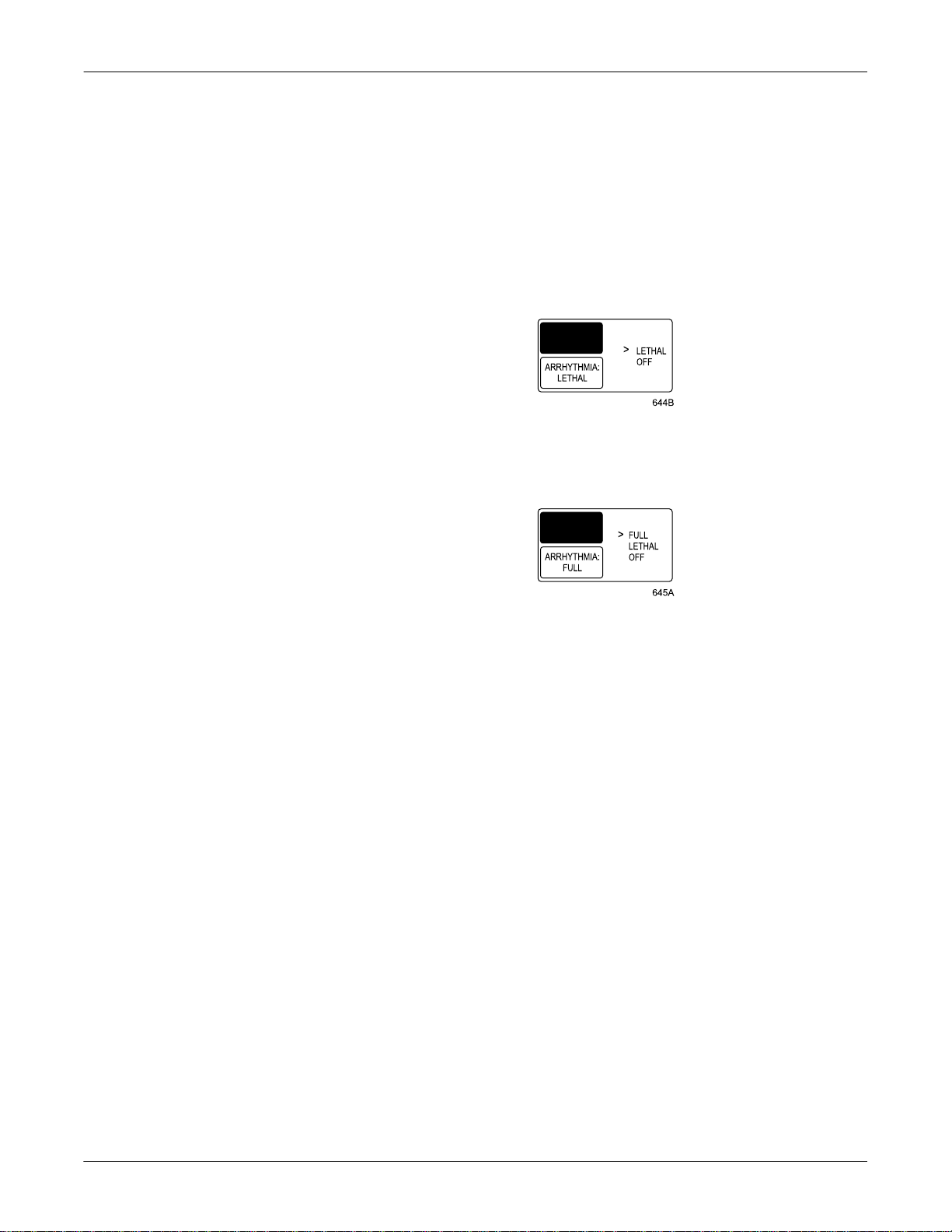
2. Select the ARRHYTHMIA option from the ECG menu.
If you have the Basic software package, the Arrhyt hmia popup menu
will look like this illustration:
↓ ↑
Arrhythmia Popup Menu — Basic Software Package
If you have the Cardiac software package, the Arrhythmia popup
menu will look like this illustration:
↓↓
↑
Arrhythmia Popup Menu — Cardiac Software Package
To determine if the Cardiopulmonary and/or High Resolution CRG
Trends options have been installed on your monitor, follow these steps.
1. Select MORE MENUS from the monitor’s main display.
2. Select MONITOR SETUP from the menu displayed.
3. Select REVISION AND ID from the Monitor Setup menu. A popup
menu and information window appear.
4. Select NEXT in the popup menu a s many ti mes as ne cessar y to scroll
through the information windows until the SOFTWARE OPTIONS
DISPLAY information window appears.
5. In the Software Options Display information window, the word
“Enabled” appears below CARDIOPULMONARY FEATURES and/or
HI RES GRAPHIC TRENDS if one or both options have been
purchased and installed.
Revision A Solar 8000i Patient Monitor 1-5
2026265-001
Page 22
Menus
Main Display
The Basics: Menus
There are several types of menus foun d on the So lar 8000 i monitor. T hey
are described below.
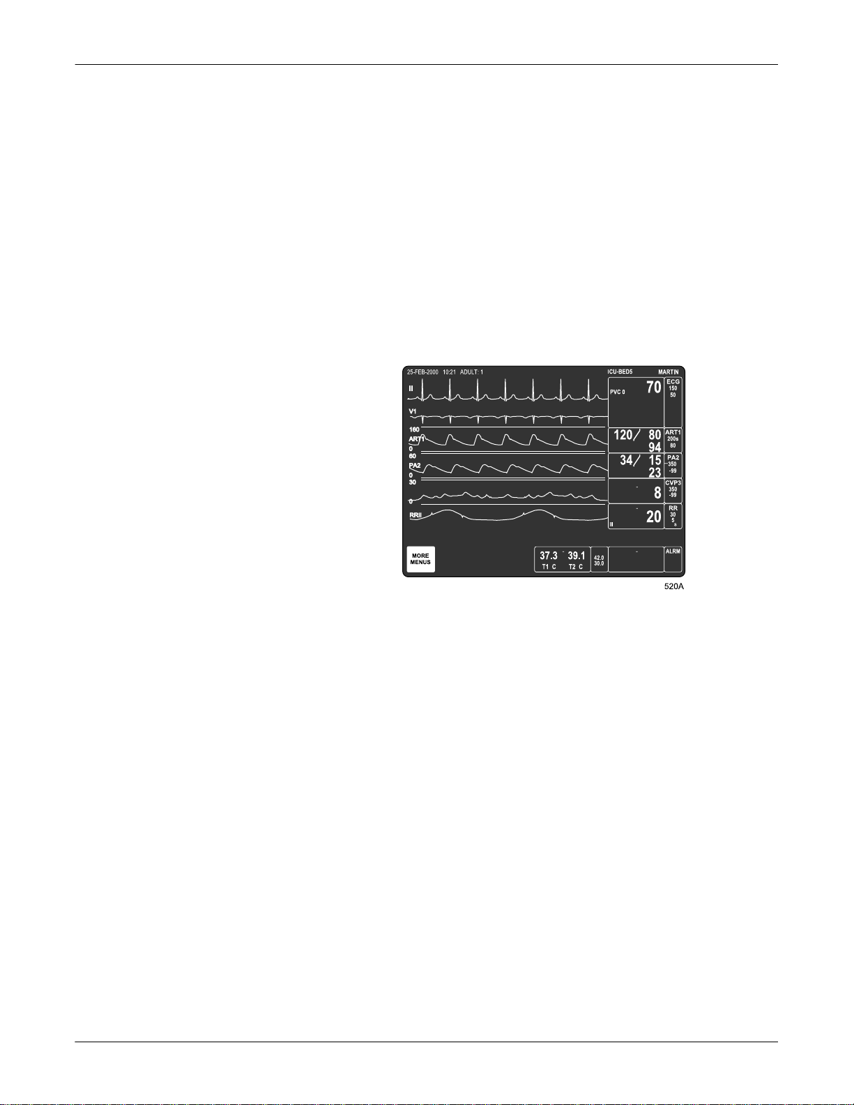
The main display sho ws all monitored p arameters and waveforms. It also
contains the main menu in the lower left corner of the screen. The main
menu consists of one menu option, MORE MENUS. You can access
menus not related to specific parameters by selecting the MORE
MENUS option. You can also access parameter menus by selecting the
parameter labels. The main display is shown below.
mmHg
D
mmHg
Menu Timeout
mmHg
20
TP1
Solar 8000i Main Display
The monitor automatically returns to the main display when you have
displayed another menu and have not used the Trim Knob control or
touchscreen for 5 minutes (default time). This is a monitor default
display setting, which can be set for a longer period of time or for no
timeout at all. Some menus, such as Vital Signs and Trends, are not
affected by the timeout setting. You must exit them using the MAIN
MENU or PREVIOUS MENU option.
1-6 Solar 8000i Patient Monitor Revision A
2026265-001
Page 23
More Menus
The Basics: Menus
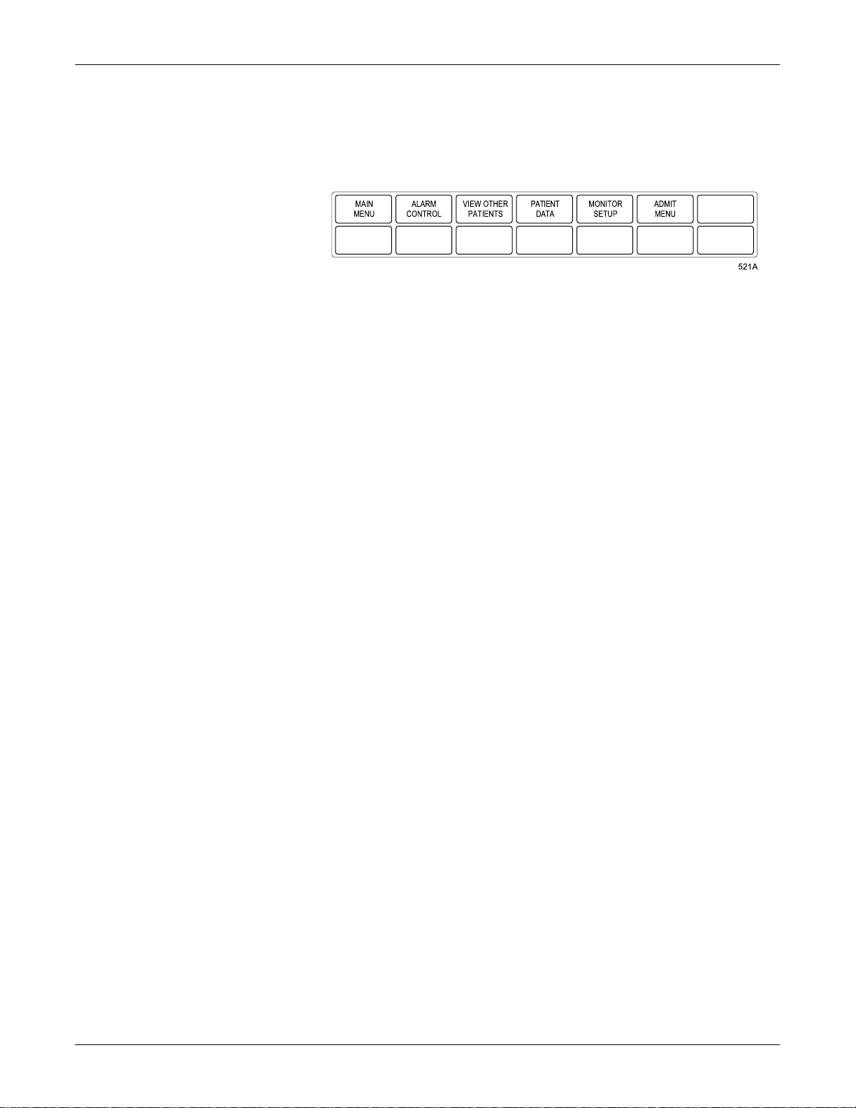
Selecting the MORE MENUS option from the main menu opens the
following menu.
MAIN MENU — Returns to the main display with the MORE
MENUS menu option visible.
ALARM CONTROL — Displays the Alarm Control menu.
VIEW OTHER PATIENTS — Displays the View Other Pati ents
menu.
PATIENT DATA — Displays the Patient Data menu.
MONITOR SETUP — Displays the Monitor Setup menu.
ADMIT MENU — Displays the Admit menu. In Operating Room
mode, this option is labeled NEW CASE SETUP.
Each of these menus is discussed in more detail in following chapters.
Revision A Solar 8000i Patient Monitor 1-7
2026265-001
Page 24
Popup Menus
The Basics: Menus
When some menu options are selected, a small menu “pops up” around
the selected menu option. These small menus are called popup menus.
The most common types of popup menus are described below.
NOTE
With all popup menus, the original menu remains on the screen, but
the other options are dimmed. The popup menu must be closed before
you can select other options from the original menu.
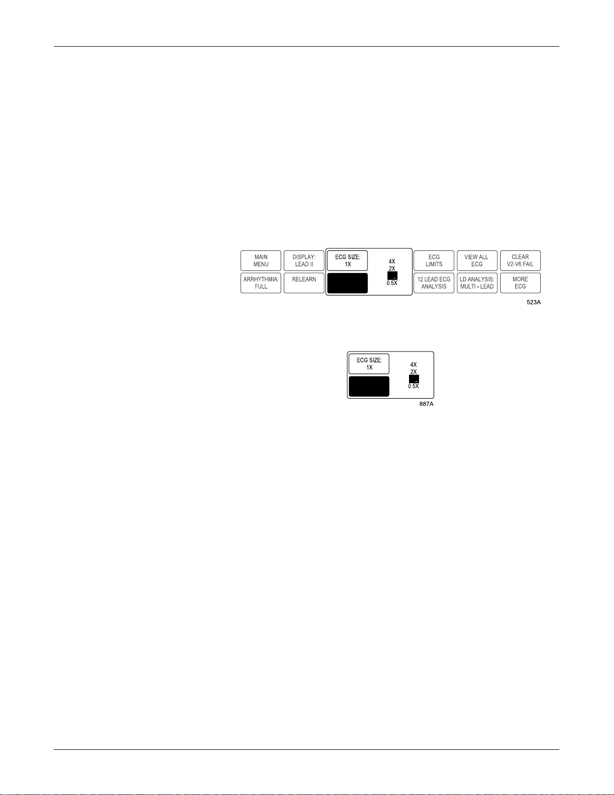
Frequently in this manual, only the popup menu is shown, rather than
the popup menu and the dimmed menu options. Examples of both are
shown below.
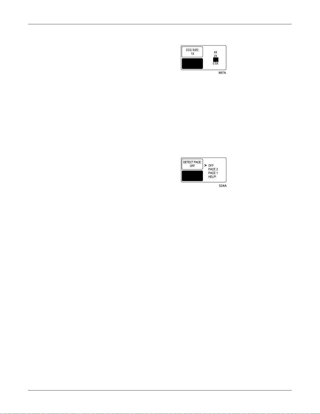
1X
↓ ↑
ECG Size Popup Menu with Dimmed Menu Options
(as it appears on the monitor’s display)
1X
↓ ↑
ECG Size Popup Menu Only (as it appears in this manual)
1-8 Solar 8000i Patient Monitor Revision A
2026265-001
Page 25
Scrolling Popup Menu
↑
Pointer Popup Menu
The Basics: Menus
1X
↓ ↑
Scrolling Popup Menu
In a scrolling popup menu, all available selections appear, with the
current selection highlighted. The Trim Knob control can be rotated, or
the touchscreen arrows can be touched, to change the selection. This is
called “scrolling.” The new selection is highlighted, and the change
appears on the display immediately, allowing the user to see if the
selection is appropriate. Pressing the Trim Knob control or touching the
anchor menu option selects the highlighted option and closes the popup
menu.
↓↓
↑
Pointer Popup Menu
In a pointer popup menu, all available selections and a pointer (>)
appear. The Trim Knob control can be rotated or the touc hscreen arrows
can be touched to move the pointer to another selection. Pressing the
Trim Knob control or touching the anchor menu option implements the
change and closes the popup menu.
Revision A Solar 8000i Patient Monitor 1-9
2026265-001
Page 26

Numeric Popup Menu
The Basics: Menus
↓ ↑
Numeric Popup Menu
Because there are many selections available, only the current selection is
displayed in a numeric popup menu. Use the number buttons on the
keypad or remote control to enter a new value. Rotating the Trim Knob
control or touching the touchscreen arrows also changes the displayed
value in the popup menu. You must press the Trim Knob control or touch
the anchor menu option to implement the change and close the popup
menu.
NOTE
When a numeric popup menu i s open , the bu tt ons on the key pa d a nd
remote control can only be used to enter numbers. Close the numeric
popup menu to access features using these buttons.
1-10 Solar 8000i Patient Monitor Revision A
2026265-001
Page 27
Subordinate Menus
The Basics: Menus
In some cases when selecting menu options, a whole new menu is
displayed. This is called a subordinate menu.
Below is an example that shows how to access a subordinate menu.
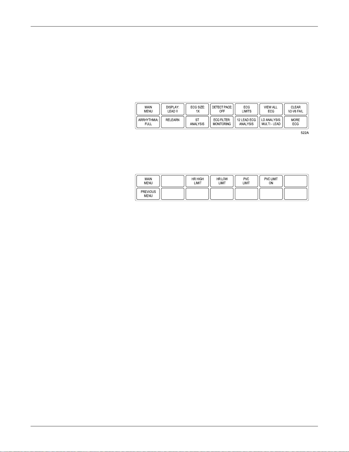
1. Select the ECG parameter label to display the ECG menu.
ECG Menu
2. Select ECG LIMITS. The entire ECG menu is replaced with the
subordinate ECG limits menu.
ECG Limits Menu
3. Select PREVIOUS MENU to redisplay the ECG menu.
NOTE
Many, but not all, subordinate menus have the PREVIOUS MENU
option to allow you to return to the previously displayed menu.
526A
Revision A Solar 8000i Patient Monitor 1-11
2026265-001
Page 28
Direct Action Menu Options
A direct action menu option either turns a feature on or off, or starts a
processing function.
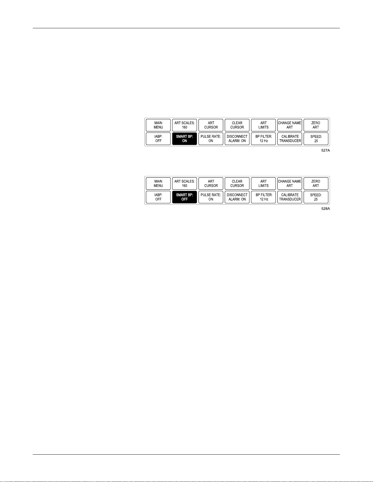
Some direct action menu options turn a feature on or off. For example,
selecting the SMART BP: ON option from the ART parameter menu
turns the Smart BP feature off. In on/off cases, the menu option label
reflects the current state; selecting it switches to the other state.
The Basics: Menus
SMART BP: ON
SMART BP: OFF
Some direct action menu options start a process. For example, selecting
the RELEARN option from the ECG parameter menu tells the monitor to
immediately relearn the patient’s ECG rhythm. These processes cannot
be stopped, as they are s hort-term and st op automatica lly. Theref ore, the
menu option label does not change as it does in on/off cases.
1-12 Solar 8000i Patient Monitor Revision A
2026265-001
Page 29
Windows
Parameter Windows
The Basics: Windows
There are two types of windows found on the Solar 8000i display. They
are described below.
Parameter windows are displayed on the right side of the display, and
when necessary, along the bottom of the display. Every monitored
parameter has a parameter window.
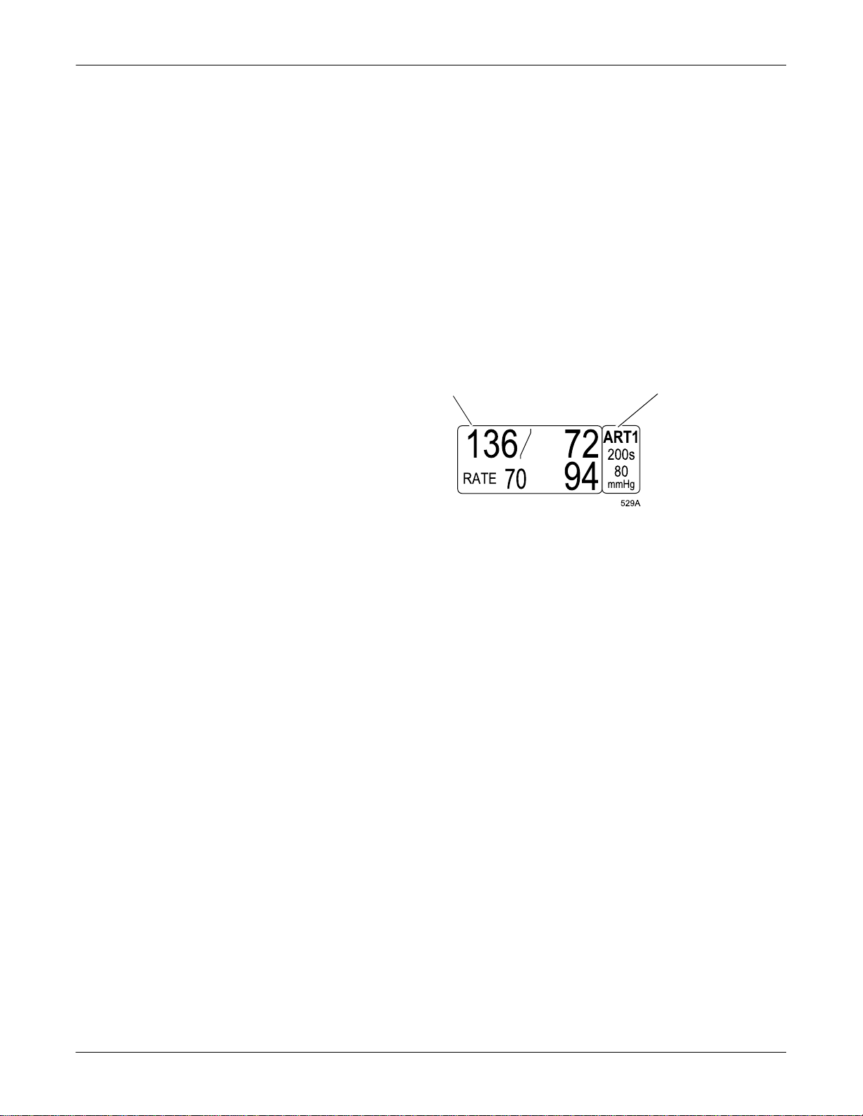
Each parameter window has two parts, a parameter label and a digital
values area. Depending on your default settings, limits and units of
measure may be displayed under the parameter label.
Digital Values Parameter
Label, Limits,
Units of
Measure
ART Parameter Window
Revision A Solar 8000i Patient Monitor 1-13
2026265-001
Page 30
The Basics: Windows
If many parameters are being monitored, some of the parameter
windows at the bo tt om o f t he dis pla y ma y be reduce d i n s ize . Bel ow is an
example of a parameter window at its normal size and at its reduced size.
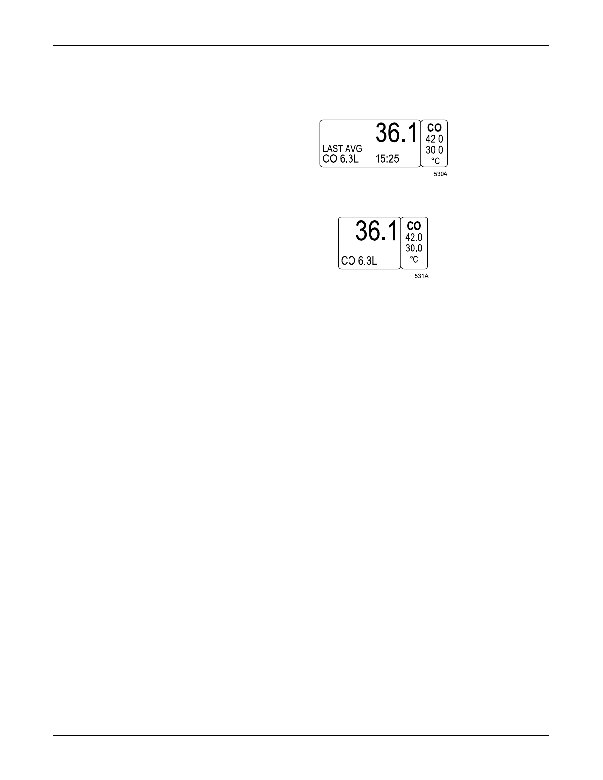
CO Parameter Window, Normal Size
CO Parameter Window, Reduced Size
The parameters that may be displayed at reduced size when positioned
at the bottom of the display are: CO, CVP, ICP, LA, RA, RR, SP, SPO2,
SVO2, TP, UO, UVC, and VNT.
1-14 Solar 8000i Patient Monitor Revision A
2026265-001
Page 31

Information Windows
The Basics: Windows
Information windows are superimpos ed over the upper left porti on of the
display. Six parameter windows and two seconds of all real-time
waveforms continue to be displayed.
Information windows are displayed when a help option is selected and
with certain menu options such as limits. Information windows can
contain instructions or other information related to the parameter or
menu.
Information Window
More
Information
Indicator
Real-time
Waveforms
LAST AVG
CO 6.3L 15:25
Vital Signs Information W indow
Sometimes an information window contains a list, as in the Vital Signs
information window shown above. A limited amount of informat ion can
be displayed at one time. If there is more information to view, an arrow is
displayed at the bottom of the information window.
Revision A Solar 8000i Patient Monitor 1-15
2026265-001
Page 32

The Basics: Windows
If a popup menu is displayed with the informa tion window, use the Trim
Knob control or touchscreen arrows to scroll to more information. If a
menu is displayed, as in the example above, you must select the PAGE
UP or PAGE DOWN option to display more information.
There is more information. Scroll down or use the PAGE DOWN
È
option to display more information.
ÇÈ
Ç
You are in the middle of t he list. Scroll up or down, or use t h e
PAGE UP or PAGE DOWN option to display additi onal
information.
You are at the end of the list. Scroll up or use the PAGE UP option
to display the previous information.
1-16 Solar 8000i Patient Monitor Revision A
2026265-001
Page 33

The Basics: Common Operations
Common Operations
Some monitor operations are used repetitively. Rather than listing the
steps to perform each operation every time it appears in this manual,
these steps are presented below. Familiarize yourself with the proper
procedure for each operation.
Using the Trim Knob Control
The Trim Knob control is found on the keypad and remote control. Refer
to Chapter 2, Equipment Overview, for details regarding its location and
appearance.
The Trim Knob control is used for highlighting and selecting.
To highlight with the Trim Knob control:
Rotate the Trim Knob control in either direction. This moves the
“highlight” (reverse video) on the screen up, down, left, or right to the
next option, depending on the type of menu that curre ntly appea rs on the
display.
NOTE
In some cases, rather than highlighted text, a pointer (>) appears in
front of the text. When a pointer is present, rotating the Trim Knob
control moves the pointer to another option. This is equivalent to
highlighting.
To select with the Trim Knob control:
First, highlight your desired menu option (or move the point er in front of
it), as described above. Once you have highlighted the option, press the
Trim Knob control once to select it.
NOTE
This manual refers to the Trim Knob operation of highlighting a
menu option and then selecting it as “select.”
You can also use this procedure to select the parameter labels found in
the parameter windows. Simply rotate the Trim Knob control until the
parameter label (e.g., ECG) is highlighted, then press the Trim Knob
control to select it. The corresponding parameter menu will then appear
at the bottom of the display.
Revision A Solar 8000i Patient Monitor 1-17
2026265-001
Page 34

The Basics: Common Operations
Using the Touchscreen Display
NOTE
The touchscreen display is an optional feature.
A touchscreen display (or simply touchscreen) is a screen that ha s areas
that are sensitive to touch. These areas are:
Anywhere inside a parameter window.
Any menu or menu option.
The touchscreen feature does not function properly if tape or paper is
stuck to the screen’s surface. Pencils, pens, and other sharp, pointed
objects should not be used to activate the touchscreen.
When you have selected a touchscre en i tem, a n audi ble t one sounds . The
volume of this tone can be adjusted in the Setup Default Display menu
using the Touch Volume option.
Touching any parameter label opens the parameter menu. Touching
MORE MENUS on the main display opens a set of menu options used to
access menus that are not related to specific parameters.
Once a menu is open, you can touch any of the menu options to:
Open a popup menu.
Open a popup menu and information window.
Open a submenu.
Perform a direct action.
The result of touching a menu option depends on the option selected.
Touching a menu option is equivalent to highlighting it by rotating the
Trim Knob control, then pressing the Trim Knob control. This manual
refers to this process as “selecting.”
1-18 Solar 8000i Patient Monitor Revision A
2026265-001
Page 35

The Basics: Common Operations
Using the Touchscreen with Popup Menus and Information Windows
When a menu option is selected (touched), and a popup menu or a popup
menu and information w indow open, touchscreen arrow options and/or a
RETURN option may appear in the popup menu. In addition, the menu
option selecte d now serves as an anchor menu option and is used as part
of the selecting process.
Anchor Menu Option
↓ ↑
Touchscreen
Arrows
Arrhythmia Alarm Level Popup Menu and Information Window
RETURN option
Touchscreen Arrows
Touchscreen arrows can be touched to move up, down, left, or right.
Touching an arrow once will move it to the next option. Touching and
holding your touch on an arrow will scroll th rough the options until you
release your touch.
Popup menus may have both the up/down arrows and the left/right
arrows, or only one set may appear. The currently active set of arrows is
highlighted. Touch the other set to activate it when needed.
For example, in the illustration above, touching the down arrow option
once would move the cursor in the information window in front of
ASYSTOLE.
Revision A Solar 8000i Patient Monitor 1-19
2026265-001
Page 36

The Basics: Common Operations
Anchor Menu Option
Once a popup menu is open, the menu option is referred to as the anchor
menu option. For example, in the illustration on the previous page, the
ARRHYTHMIA ALARM LEVEL option is the anchor menu option.
The anchor menu option can be touched as an equiva lent to pressing the
Trim Knob control. This i s the second step of the “selecting” process. For
example, in the illustration on the previous page, after moving the cursor
in front of V BRADY with the down arrow option, you would touch the
ARRHYTHMIA ALARM LEVEL anchor menu option. The V Brady
alarm level (CRISIS) would then be highlighted so the alarm level could
be adjusted.
RETURN Menu Option
Touch the RETURN menu option in any popup menu to close the popup
menu.
When an information window is displayed, touch the RETURN menu
option in the popup menu at any time to close the information window.
It is also possible to select the RETURN option in an information window
by using the touchscreen arrows to place the cursor in front of it, then
touching the anchor menu option. The information window and popup
menu will close. However, the RETURN option in the information
window is not directly touch se nsitive i tself. On ly the RETURN opt ion in
the popup menu is directly touch sensitive.
When you are finished making changes, select the RETUR N option to
close the popup menu and information window.
1-20 Solar 8000i Patient Monitor Revision A
2026265-001
Page 37

The Basics: Common Operations
Entering Alphanumeric Characters
Occasionally, a popup menu or information window requires
alphanumeric input, such as patient information or a password. The
example below describes how to enter alphanumeric characters when
changing admit information. Use the same procedure in other
alphanumeric situations.
1. Access the Change Admit Info information window and popup menu:
a. Select MORE MENUS from the main display.
b. Select ADMIT ME NU. An information window and a new menu
are displayed.
c. Select CHANGE ADMIT INFO from the menu. A popup menu
opens.
CHANGE
ADMIT INFO
↓ ↑
Change Admit Info Popup Menu and Information Window
Revision A Solar 8000i Patient Monitor 1-21
2026265-001
Page 38

The Basics: Common Operations
2. Move the cursor in front of LAST NAME, then press the Trim Knob
control or touch the CHANGE ADMIT INFO option to select it. If a
name has already been entered, the selected name appears in the
Change Last Name popup menu, as shown below.
↓ ↑
Change Last Name Popup Menu
3. Select the first character block by rotating, then pressing the Trim
Knob control, or by using the touchscreen arrows.
4. To scroll through the alphanumeric characters, rotate the Trim Knob
control in either direction or use the up/down touchscreen arrows.
Press the Trim Knob control when the desired character appears.
NOTE
It is not necessary to touch the anchor menu option or press the
Trim Knob control when using the touchscreen. Simply use the
left/right arrow keys to move to the next character block after
you have reached the desired character.
5. After the character is selected, move to the next character block and
repeat the procedure.
6. Continue until you have entered all the characters.
NOTE
Alphanumeric popup menus have character limits. In this
manual, these limits are indicated wherever such popup menus
are described.
7. Select the CHANGE LAST NAME option with the Trim Knob contro l
or touchscreen. You can then select another option from the
information window, if desired.
8. When you are finished making changes, select the RETURN option
to close the popup menu and information window.
NOTE
When no information window appears on the display, step 8 is
not necessary. Upon sel ecting the menu option in the popup
menu (step 7), the popup menu closes and function of the Trim
Knob control returns to the menu.
1-22 Solar 8000i Patient Monitor Revision A
2026265-001
Page 39

Setting Alarm Limits
The Basics: Common Operations
Each parameter menu has an option to set the alarm limits for the
monitored aspects of that parameter. The monitor’s response when a
limit is violated depends on the alarm level for which the parameter is
set. Refer to Chapter 8, Alarm Control, for details on the alarm levels
and the monitor’s response.
Regardless of the parameter, all alarm limits are adjusted in the same
way. The procedure below describes how to set alarm limits for the ART
parameter. Follow this pro c edu re to set all other parameter alarm limits.
1. Select the ART parameter label. The ART menu appears at the
bottom of the screen.
2. Select the ART LIMITS option from the ART menu. An information
window and a new set of menu options are displayed.
Pressure Parameter
High Range
High Limit Setting
Low Limit Setting
Low Range
ART Limits Menu and Information Window
The information window shows the limit ranges and th e current set
limits. The pointer (>) indicates the current value of that parameter
for the monitored patient. The pointer moves as the current value of
that parameter changes.
Revision A Solar 8000i Patient Monitor 1-23
2026265-001
Page 40

The Basics: Common Operations
3. To change a limit, for example, the Rate High Limit, select the RATE
HIGH LIMIT option from the limits menu. A popup menu opens,
displaying the current limit.
4. You can enter a new limit value in three different ways:
a. Use the number buttons on the keypad or remote control.
b. Rotate the Trim Knob contro l.
c. Use the touchscreen arrows to change the value.
The bar graph in the information wi ndow is adjust ed to show the new
limit.
If a value entered for one limit exceeds the opposite limit for the
same parameter, the value will be i gnored. For example, using the
limits shown in the illustration on the previous page, if you were to
enter a value of 40 for the RATE HIGH LIMIT, it would be ignored
because the RATE LOW LIMIT is set to 50.
Regardless of the method used to enter a new value, the limit will not
be in effect until you press the Trim Knob control or touch the Rate
Limit menu option (anchor menu option), closing the popup menu.
5. Follow this procedure to set any other parameter limits in this menu.
6. When you are finished, select PREVIOUS MENU to exit the limits
menu and return to the parameter menu.
1-24 Solar 8000i Patient Monitor Revision A
2026265-001
Page 41

The Basics: Common Operations
Selecting Options from Scroll Lists
Various features of the monitor can be set up using scroll lists. In a scroll
list, the currently selected option is the only one shown. However,
selecting the option and then rotating the Trim Knob (or using the
touchscreen arrows) allows you to scroll through the other choices and
select one, if desired.
For example, the Arrhythmia Alarm Levels information window uses
scroll lists to set the alarm level for each arrhythmia call. The steps
below demonstrate how to select and change an option in the Arrhy thmia
Alarm Levels information window. In this example, V BRADY is changed
from a Crisis level to a Warning level.
1. Access the Arrhythmia Alarm Level popup menu and information
window by selecting MORE MENUS from the main display. Select
ALARM CONTROL from the menu that appears, then select
ARRHYTHMIA ALARM LEVEL. The Arrhythmia Alarm Level
popup menu and information window open.
↓ ↑
Arrhythmia Alarm Level Popup Menu and Information Window
Revision A Solar 8000i Patient Monitor 1-25
2026265-001
Page 42

The Basics: Common Operations
2. Rotate the Trim Knob control or use the touchscreen arrows to move
the pointer (>) next to V B RA DY .
3. When the poin ter is next to V BR ADY, push the Trim Knob control or
touch the ARRHYTHMIA ALARM LEVEL menu option (anchor
menu option). The alarm level (in this case CRISIS) for V BRADY
highlights.
4. Rotate the Trim Knob control or use the touchscreen arrows to scroll
through the options.
5. When WARNING is displayed, press the Trim Knob control or touch
the ARRHYTHMIA ALARM LEVEL menu option (anchor menu
option) to complete the change. The change takes effect immediately,
and the information window remains open to make other changes.
6. When you are finished making changes, sele ct RETURN to close the
information window.
1-26 Solar 8000i Patient Monitor Revision A
2026265-001
Page 43

The Basics: Language-Specific Information
Language-Specific Infor m ation
The following information describes differences in Solar 8000i monitor
functionality when the monitor is se t to certain languages.
Chinese and Japanese Language Information
When the Solar 8000i monitor language is set to Chinese or Japanese,
the following conditions apply:
Text for alarm broadcast over the Unity network is in English.
All text input is in English only (i.e., text for patient information, bed
and unit names, printer names).
French Language Information
When the Solar 8000i monitor country selection is set to France, alarm
pause duration is three minutes. Refer to the “Pausing Alar ms” section
in Chapter 8, Alarm Control.
Hungarian, Polish and Russian Language Information
Alarm broadcasts sent over the Unity network cannot be received by
equipment that does not suppo rt these l anguages . Mes sages ar e receiv ed
as a series of square boxes because the ability to display Cyrillic (Russian
alphabet) and special Hungarian and Polish characters does not exist on
this equipment. This is also true when a patient name, site name, or
location containing Cyrillic or special Hungarian or Polish characters is
sent to the MUSE system.
Revision A Solar 8000i Patient Monitor 1-27
2026265-001
Page 44

For your notes
The Basics: Language-Specific Information
1-28 Solar 8000i Patient Monitor Revision A
2026265-001
Page 45

2 Equipment Overview
Revision A Solar 8000i Patient Monitor 2-1
2026265-001
Page 46

Equipment Overview: Components
Components
Solar 8000i Patient Monitoring System
The Solar 8000i monitoring system consists of the following standard
components:
Solar 8000i processing unit
Display
Keypad and/or remote control
Acquisition module(s)
Tram-rac housing
Additional, option al components include:
Touchscreen display
Clinical Information Center (central station)
Remote display
Writer or printer
Octanet connectivity device or Unity Network ID connectivity device
iPanel
™
computer
The components of the system are discussed and illustrated on the
following pages. For complete setup information, refer to the service
manual.
2-2 Solar 8000i Patient Monitor Revision A
2026265-001
Page 47

Solar 8000i Processing Unit
Equipment Overview: Components
Connectors are located on th e processing unit. Patient data is displayed
on a separate display unit.
M-ports
890C
Front View of the Processing Unit
M-Ports
There are four M-ports on the front of the 8000i processing unit. The
M-ports are used to connect external devices to the Solar 8000i monitor.
The following devices can be directly connected to the M-ports:
Solar 8000i keypad
Solar 8000i remote control
PRN 50-M digital writer
Laser printer
Unity Network ID connectivity device
Respiratory mechanics module (RM-M module)
RAMS M-200 system
NOTE
If the PRN 50 writer, respiratory mechanics module, or RAMS
system does not function when conne cted to an M-port, y ou may need
an AutoPort to M-port adapter. Refer to Chapter 7, Printing, for
connection information for the PRN 50 writer, and to the Solar 8000i
Patient Monitor Service Manual for additional information about all
three devices.
Revision A Solar 8000i Patient Monitor 2-3
2026265-001
Page 48

Equipment Overview: Components
Ethernet
connector
Video (display) connectors
Tram-net connectors
NOTE
Back View of the Processing Unit
RS-232 connectors
The number of video
connectors varies by
2-4 Solar 8000i Patient Monitor Revision A
2026265-001
Page 49

Solar 8000i Display Unit
Equipment Overview: Components
The Solar 8000i display unit is connected by cable to a video connector on
the processing unit. A selection of different color displays is offered to
accommodate different needs.
WARNING
Do not connect a monochrome display to the Solar 8000i
monitor. Visual alarm indicators may not appear
properly.
Display Items
Regardless of the size or type of display unit you have, the display items
are the same. The illustration below shows a typical display with items
labeled.
Date and
Time
Name
Parameter
Waveforms
Care UnitMonitor Default
ECG
LIMITS
Bed
Number
Patient
Name
Parameter
Labels, Limits,
and Vital Signs
Menu
Options
Solar 8000i Display Items
Revision A Solar 8000i Patient Monitor 2-5
2026265-001
Page 50

Tram Modules
Equipment Overview: Components
The Tram module is an acquisition module that collects the patient’s
physiological data and sends it to the monitor for di sp lay. Tra m modules
are multi-parameter acquisition modules. Multi-parameter modules are
capable of monitoring more than one parameter simultaneously, e.g.,
ECG, SpO2, and NBP.
The type of Tram module determines what parameters it monitors. A
label on the front of the monitor identifies the type of module.
The label is
located on this
panel.
567A
Tram 451N Module
These series of Tram modules are discussed in this document:
Tram x00
Tram x00A
Tram x00SL
Tram x50SL
Tram x51
Tram x51M
Tram x51N
The “x” refers to the “hundred series” number of the module, e.g., Tram
600SL, Tram 851N.
2-6 Solar 8000i Patient Monitor Revision A
2026265-001
Page 51

Tram x51 Series Modules
Equipment Overview: Components
The x51 series is the current series of Tram modules. Refer to the table
below to determine your Tram x51 series module’s monitoring features.
Tram
Module
451
451M
451N
851
851M
851N
12-Lead ECG
Analysis
Resp Temp/CO
Dinamap
NBP
9 9 9 9
9 999
9 9 9 9
Invasive
BP
*
3/4
*
3/4
*
3/4
Masimo
GE SpO2
†
SpO2
9 9
99
Nellcor
†
SpO2
Defib/
†
Sync
9 9
9 999 9 9
9 9 9 9 9 9
9 999 99
*
A Y-adapter cable is required to monitor four invasive blood pressures.
†
Different SpO2 cables are required for each type of SpO2 processing.
The cable connectors are not interchangeable.
‡
The Defib Sync connector on x51 series modules requires a
DIFFERENT cable than the other Tram module series. They are not
interchangeable. The cable for the x51 series modules has a 7-pin
connector.
‡
Revision A Solar 8000i Patient Monitor 2-7
2026265-001
Page 52

Tram Module Y-Adapter Cable
The Tram 451 series modules can monitor four invasive blood pressures
when a Y-adapter cable is used. This cable plugs into the BP3 connector
on the module, and allows two separate invasive blood pressures to be
monitored from that connector.
Tram 451N Module with Y-Adapter Cable Connected to BP3 Connector
This cable is designed to fit only in the BP3 connector. Do not a t te mpt to
plug it into any other connector; it will not function.
Equipment Overview: Components
539A
The Y-adapter cable can ONLY be used with Tram 451 series modules. It
cannot be used with any other Tram module series.
2-8 Solar 8000i Patient Monitor Revision A
2026265-001
Page 53

Other Tram Module Series
Equipment Overview: Components
There are several other series of Tram modules. Refer to the table below
to determine the monitoring features of your non-x51 series module.
Tram
Module
100A
200A
200SL
250SL
400A
400SL
450SL
500A
600A
600SL
650SL
800A
800SL
12-Lead ECG
Analysis
Resp Temp/CO NBP*
9 9 9
999
9 9 9 9
9 999
9 9 9
9 999
9 9 9 9
99
9 9
999
9 9 9
Invasive
BP
2
2
2
2
3
3
3
4
4
4
4
SpO2
99
9 9
99
9 9
99
9 9
9 9
99
9 9
999 99
9 9 9 9 9 9
Defib/
Sync
9
9
850A
850SL
999 99
9 9 9 9 9 9
* Tram module software versions 10B and later use the Dinamap NBP
algorithm. Software versions 10A and earlier use the GE Medical
Systems Information Technologies NBP algorit h m .
Tram x00, x00A, and x00SL modules with SpO2 are compatible with
Ohmeda probes.
Tram x50SL modules are compatible with Ne llcor and GE Medical
Systems Information Technologies probes.
Although not shown in the table above, Tram x00 modules have the same
features as the x00A modules. However, Tram x00 modules are not
compatible with the selectable lead, 3-lead ECG cable.
Revision A Solar 8000i Patient Monitor 2-9
2026265-001
Page 54

Equipment Overview: Components
Tram Module Front Panel Connectors
Below are two examples of T ra m modules . The co nnect ors on the fro nt of
the module are labeled. Some Tram modules have different NBP and
SPO2 connectors, but t hey are located in the same position as those
shown below.
ECG/Resp
Power
Indicator
Light
ECG/Resp
Temp/CO
BP 1 BP 2 BP 3/4
Transport
Display
Defib/Sync
Front Panel of Tram 4 51N Module
Temp/CO
NBP
SPO2
545A
NBP
Power
Indicator
Light
Transport
Display
Defib/Sync
Front Panel of Tram 850SL Module
SPO2
2-10 Solar 8000i Patient Monitor Revision A
2026265-001
Page 55

Equipment Overview: Components
The Defib/Sync connector pro vi des ana l og out put signa ls (a n EC G sign al
and a blood pressure signal, if available) to user-supplied equipment. A
5-volt, 2-millisecond artificial pacer spike is added to the analog output
when PACE is on and detection occurs. Refer to Chapter 21, Appendices,
for details on signal outputs, and to the Tram module service manual for
signal connector pin configuration.
Single-Parameter Modules
Single-parameter acquisition modules also collect the patient’s
physiologica l data and send it to the monitor for display. Single
parameter acquisition modules are available to monitor a wide variety of
parameters, such as ECG, BP, NBP, CO2, SpO2, and SvO2.
Single-Parameter ECG/Resp Module
Single-parameter modules can be used for ECG acquisition in place of
the multi-parameter Tram module. There are four different singleparameter ECG/Resp modules. The chart below shows the features of
each.
ECG/Resp Module Features
Module
ECG/RESP No Yes No
ECG/RESP No Yes Yes*
ECG/RESP SL Yes Yes No
ECG/RESP SL Yes Yes Yes*
*There is a Defib Sync connector on the modules that have this
feature.
Front Panel of ECG/Resp SL Module with Defib Sync
12-Lead ECG
Analysis
Resp Defib/Sync
Revision A Solar 8000i Patient Monitor 2-11
2026265-001
Page 56

Equipment Overview: Components
Status Indicator Light
There is a STATUS indicator light on each ECG/Resp module. A green
status light indicates a normal condition.
If the status light is yellow, check for system compatibility:
Verify that the monitor is a Solar monitor.
Verify that the Tram-rac housing is a Tram-rac 4A housing.
If you can verify both of these, call your biomedical department for
further assistance.
Defib Sync Connector
The DEFIB. SYNC. connector provides analog output signals to usersupplied equipment. A 5-volt, 2 -millisecond artifi cial pacer spike is adde d
to the analog output when PACE is on and detection occurs. Refer to
Chapter 21, Appendices, for details on signal outputs, and to the
appropriate module service manual for signal connector pin
configuration.
2-12 Solar 8000i Patient Monitor Revision A
2026265-001
Page 57

Tram-rac Housing
Equipment Overview: Components
The Tram-rac housing holds the Tram module and other GE Medical
Systems Information Technologies parameter modules. The housing is
connected by cable to the monitor, using a Tram-net connector.
The Tram-rac 2 housing holds one Tram module. The Tram-rac 4A
housing holds one Tram module plus two parameter modules.
Multiple Housings
T ram-rac 4A Housing
You can connect an additional housing to a Tram-rac 4A housing to allow
for monitoring additional parameters. Refer to the Tram-rac 4A service
manual for details on setup.
When using two housings, follow these guidelines:
One housing must have a power supply.
Only one ECG source module can be used.
If the second housing is NOT a Tram-rac 4A housing, the Tram
module must go in the second housing.
Single-parameter BP and temp modules can only be placed in the
bottom two positions of a housing.
Revision A Solar 8000i Patient Monitor 2-13
2026265-001
Page 58

Housing Connectors
Equipment Overview: Components
All housings have a Tram-net connector. Except for the Tram-rac 2
housing, all housings also have an analog outp ut connector. The analog
output connector provides data from the monitor to other user-supplied
equipment. (Refer to Chapter 21, Appendices, for details.) Depending on
the type of Tram-rac housing, th e connectors may be located on th e front,
the back, or both.
The Tram-net connectors are on the back panel.
Analog Output
Connector
ANALOG
TRAM
TRAM
NET
OUT
NET
Two Tram-net
Connectors
TRAM-RAC Ports
CAUTION
V~
100–120V
220–240V 500mA
50-60 Hz
TRAM
TRAM
NET
NET
I
1A
Back Panel of Tram-rac 4A Housing
NOTE
The Solar ECG module does not support analog output from the
Tram-rac analog output connector. When using the Solar ECG
module, analog output is only available from the optional Defib Sync
connector on the front of the module.
2-14 Solar 8000i Patient Monitor Revision A
2026265-001
Page 59

Equipment Overview: Components
The Tram-rac 2 housing does not have an analog outpu t connector. The
Tram-net connector is on the back.
TRAM- RAC2
marquette
Tram-net Connector
Front and Back Panels of Tram-rac 2 Housing
Revision A Solar 8000i Patient Monitor 2-15
2026265-001
Page 60

Features of the Housing
Equipment Overview: Components
The housing has “slots,” whi ch are use d to hold modules. Mo dules occup y
either one or two slots. All Tram modules occupy two slots, and must be
placed in the top two slots of the housing.
There are numbers on each side of each slot on the housing. These
numbers have significance when duplicate parameters are being
monitored. The number displayed with the parameter label on the
monitor — i.e., ART1, PA2 — indicates that the module is in the samenumbered slot. For example, if you have an ART5 parameter label on the
monitor, this means that a pressure module is in slot 3, and an ART line
is connected to that module.
Slot 1
Slot 2
Slot 3
Slot 4
Tram-rac Housing Slots
2-16 Solar 8000i Patient Monitor Revision A
2026265-001
Page 61

Equipment Overview: Components
Installing and Removing Modules
Acquisition modules are easily installed and removed. A Tram module
must always occupy the top position in the Tram-rac housing. Other
modules are installed below it.
To install a module:
1. Facing the Tram-rac housing, guide the back of the module into the
appropriate position.
2. Gently push the module into the housing. You will hear a click when
the module is fully inserted.
To remove a module:
1. Push the module into the Tram-rac housing. This releases the
module and makes it easier to remove.
2. Press and hold the release levers found on each side of the front of
the module.
3. Pull the module out about 6 inches (15 cm).
4. Grasp the module firmly with both hands and remove it. Do not try
to hold the module by the release levers.
The release levers for Tram modules are recessed in the side of the
protruding front of the module.
Tram-rac Housing
Release Levers
Removing a Tram Module
Revision A Solar 8000i Patient Monitor 2-17
2026265-001
Page 62

Equipment Overview: Components
Optional Clinical Information Center
The Unity Network (Ethernet) establishes communication and allows
patient data to be sent to an optional Clinical Information Center
(central station). Refer to the Clinical Information Center Operator’s
Manual for operating instructions.
Optional Writers and Printers
For information about writers and printers available for the Solar 8000i
monitor, refer to Chapter 7, Printing.
Optional Remote Display
An optional remote display can be connected to the system to provide
enhanced visibility.
Clinical Information Center
2-18 Solar 8000i Patient Monitor Revision A
2026265-001
Page 63

Equipment Overview: Components
Optional Connectivity Dev ices
For information about the Unity Network ID connectivity device and the
Octanet remote connectivity device, refer to Chapter 20, Interfaces.
Optional iPanel Computer
For information about the iPanel computer, refer to the iPanel computer
‘operator’s instructions and/or administrator’s manual.
Revision A Solar 8000i Patient Monitor 2-19
2026265-001
Page 64

Controls
Keypad
Equipment Overview: Controls
The Solar 8000i monitor keypad has a Trim Knob control, as well as 18
buttons that can be used to access various operational features of the
monitor. Some buttons are also labeled with numbers, and can be used
for direct numeric data entry.
The keypad may be mounted in convenient location using an optional
holster (not shown) and connected by cable to the processing unit.
There are three versions of the keypad: Adult, Neonatal, and Operating
Room. Each version features buttons that allow easy access to commo nly
performed functions for that mode. For example, the Neonatal keypad
has CRG buttons, while the Operating Room keypad has Airway Gases
buttons. The Operating Room keypad is shown below.
NOTE
The message WARNING: REMOTE MISMATCHED WITH
MONITORING MODE is displayed if the keypad type does not
match the monitoring mode. Fo r example, if an Operating Room
keypad were connected to a monitor set for the Adult-ICU monitoring
mode, this message w ould a ppe ar. Howev er, t he moni tor a nd k eypa d
will continue to function.
Solar 8000i Remote Keypad — Operating Room
2-20 Solar 8000i Patient Monitor Revision A
2026265-001
Page 65

Equipment Overview: Controls
Trim Knob Control
Operation of the Trim Knob control is described in Chapter 1, The
Basics.
Buttons
The table below shows the buttons that appear on the keypads. It also
indicates which type(s) of keypad the button appears on, and gives a brief
description of its function.
Button Keypad Type(s) Function
12-Lead Adult Opens the 12 Lead ECG Analysis menu.
Admit/Discharge Adult, Neonatal Opens a menu to admit or discharge a patient.
Airway Gases: CO2 Operating Room Opens the CO2 menu.
Airway Gases: Gas Operating Room Opens the Gas menu.
Alarm Volume Neonatal Opens a menu to adjust the audio alarm volume.
All Limits Adult, Neonatal Opens the All Limits menu to adjust the limits of currently monitored
parameters.
Cardiac Calcs Adult, Operating Room Opens the Cardiac Calcs menu.
Cardiac Output Adult, Operating Room Opens the Cardiac Output menu.
CRG Events Neonatal Opens the Document CRG Events window.
CRG Print Neonatal Prints the CRG waveforms.
CRG Recall Neonatal Opens the CRG Trends menu at the most recent CRG event.
Defaults Adult, Neonatal, Operating Room Opens the defaults menu.
Display On/Off Adult, Neonatal, Operating Room Turns the monitor display and audio items off and on. Operating power
(mains) is still on, and alarms remain active at the central station. Also
turns NBP off.
Dose Calcs Neonatal Enters the dose calculations program.
Graph Go/Stop Adult, Neonatal, Operating Room Initiates a graph run of patient data. Press the button again to stop.
Graphic Trends Adult, Operating Room Opens the Graphic Trends menu.
Main Menu Adult, Neonatal, Operating Room Returns to the main display.
Revision A Solar 8000i Patient Monitor 2-21
2026265-001
Page 66

Equipment Overview: Controls
Button Keypad Type(s) Function
NBP Auto Adult, Operating Room Opens the NBP Auto menu.
NBP Go/Stop Adult, Neonatal, Operating Room Initiates an NBP measurement. Pressing this button while a
measurement is in process stops that measurement.
NBP Stat Adult, Operating Room Starts five minutes of continuous, sequential NBP measurements.
New Case Operating Room Performs the direct action of discharging and then immediately admitting
a patient.
PA Wedge Adult, Operating Room Opens the PA Wedge menu.
QRS Volume Neonatal Opens a menu to adjust the volume of the QRS tone.
Resp Relearn Neonatal Starts a relearn of the patient’s respiration.
Silence Alarm Adult, Neonatal, Operating Room Refer to “Controlling Audio Alarms” on page 8-6 for important information
on the function of this button.
SpO2 Operating Room Opens the SpO2 menu.
Tabular Trends Operating Room Opens the Tabular Trends menu.
View Other Adult, Neonatal Opens the View Other Patients menu.
Vital Signs Adult, Neonatal Opens the Vital Signs menu.
Zero All Adult, Neonatal, Operating Room Zeros all invasive pressure lines that are open to atmosphere.
2-22 Solar 8000i Patient Monitor Revision A
2026265-001
Page 67

Remote Control
Equipment Overview: Controls
A hand-held remote control is also available. This can be used in addition
to, or instead of the keypad, allowing the clinician a greater range of
movement while operating the monitor. Like the keypad, the remote
control contains a Trim Knob control and 18 function buttons. It is also
available in three versions, Adult, Neonatal, and Operating Room.
All functions of the remote control are identical to those of the
corresponding keypad. Refer to the Keypad section in this chapter for
details.
An optional holster, shown below, is al so avail able for convenien t storage
of the remote control.
Solar 8000i Remote Control — Adult
Revision A Solar 8000i Patient Monitor 2-23
2026265-001
Page 68

Equipment Overview: Putting the Monitor Into Operation
Putting the Moni to r Into Operation
Monitor Installation and Connection
WARNING
Before using the monitor for the first time, read the
information in Chapter 3, Safety.
The operating position of the processing unit does not influence the
performance of the monitor in any way.
Choose a location that affords an unobstructed view of the display
and easy access to the operating controls.
Set up the monitor in a location that affords sufficient ventilation.
The ventilation openings of the device must not be obstructed (by
equipment, walls, or blankets, for example).
The ambient conditions specified in the technical specifications must
be ensured at all times.
The monitor is designed to comply with the requirements of IEC
60601-1/EN 60601-1.
Using the power cord supplied with the monitor, connect it to the
power line. Use only the original cord.
WARNING
To reduce the risk of electric shock, the monitor must
only be connected to a properly installed power outlet
with protective ground contacts.
For measurements in or near the heart, we recommend conn ecting
the monitor to the potential equalization system. Use the green and
yellow potential equalization cable and connect it to the pin labeled
with the symbol.
GE Medical Systems Information Technologies service is available to
connect the monitor to the Unity network (for use with a Clinical
Information Center, a QS system, a MUSE system, etc.).
2-24 Solar 8000i Patient Monitor Revision A
2026265-001
Page 69

Turning Power On
Equipment Overview: Putting the Monitor Into Operation
WARNINGS
For safety reasons, all connectors for patient cables and
sensor leads are designed to prevent inadvertent
disconnection, should someone pull on them. Do not route
cables in a way that they may present a stumbling
hazard. For devices inst alled abov e the pa tient, adequa te
precautions must be taken to prevent them from
dropping on the patient.
After connecting the monitor to the Unity network, verify
the function of the alarm system. This can be done, for
instance, by temporarily changing one of the alarm limits
to initiate an alarm.
The monitor is preset at the factory for a specific AC voltage. Before
applying power, be sure that the power requirements match your power
supply. Refer to the label on the back of the processing unit for voltage
and current requirements. Also refer to Chapter 3, Safety, for power
requirements.
Power Switch
When all cables are properly connected, press the power switch on the
processing unit to the “I” (on) position. Also turn power on to the display.
After approximately 10 seconds, a display should appear on the monitor.
Solar 8000i Processing Unit
Revision A Solar 8000i Patient Monitor 2-25
2026265-001
Page 70

Performance Check
Equipment Overview: Putting the Monitor Into Operation
After turning the monitor on, and during operation, the monitor runs
automatic self-tests. If a malfunction is detected, the monitor displays a
message and a prompt, asking if the user wishes to continue operation.
WARNING
If the “DO YOU WISH TO CONTINUE?” message
appears during monitor operation, it is the physician’s
responsibility to decide if the unit is still suitable for
patient monitoring. As a general rule, monitoring with
this unit should continue only in extremely urgent cases
and under the supervision of a physician. The unit must
be repaired before being used on a patient again. If this
message appears after power-up, the unit must be
repaired before being used on a patient.
2-26 Solar 8000i Patient Monitor Revision A
2026265-001
Page 71

3 Safety
Revision A Solar 8000i Patient Monitor 3-1
2026265-001
Page 72

For Your Safety
Intended Use
Terminology
Safety: For Your Safety
The intended use of this monitoring system is to monitor physiological
parameter data on adult, pediatric, and neonatal patients within a
hospital or facility providing patient care.
Physiological data includes the parameters covered in this manual. The
monitoring system is also int ended to provid e physi ological data ov er the
Unity network to clinical information systems. This information can be
displayed, trended, stored, and printed.
The terms danger, warning, and caution are used throughout this
manual to point out hazards and to designate a degree or level of
seriousness. Familiarize yourself with their definitions and significance.
Monitor Safety
Hazard is defined as a source of potential injury to a person.
DANGER indicates an imminent hazard which, if not avoided, will
result in death or serious injury.
WARNING indicates a potential hazard or unsafe practice which, if not
avoided, could result in death or serious injury.
CAUTION indicates a potential hazard or unsafe practice which, if not
avoided, could result in minor personal injury or product/property
damage.
NOTE provides application tips or other useful information to assure
that you get the most from your equipment.
The safety statements presented in this chapter refer to the equipment
in general and, in most cases, apply to all aspects of the monitor. There
are additional safety statements in the parameter chapters which are
specific to that monitored parameter.
The order in which safety statements are presented in no w ay i mplies
order of importance.
3-2 Solar 8000i Patient Monitor Revision A
2026265-001
Page 73

Dangers
Warnings
Safety: For Your Safety
There are no dangers that refer to the equipment in general. Specific
“Danger” statements may be given in the respective sections of this
manual.
WARNINGS
ACCIDENTAL SPILLS — To avoid electric shock or
device malfunction liquids must not be allowed to enter
the device. If liquids have entered a device, take it out of
service and have it checked by a service technician before
it is used again.
ACCURACY — If the accuracy of any value displayed on
the monitor, central station, or printed on a graph strip is
questionable, determine the patient's vital signs by
alternative means. Verify that all equipment is working
correctly.
ALARMS — Do not rely exclus iv el y o n th e a udib le al a rm
system for patient monitoring. Adjustment of ala rm
volume to a low level or off during patient monitoring
may result in a hazard to the patient. Remember that the
most reliable method of patient monitoring combines
close personal surveillance with correct operation of
monitoring equipment.
After connecting the monitor to the central station,
nurse-call system, and/or network, verify the function of
the alarm system.
The functions of the alarm sy stem for monitoring of the
patient must be verified at regular intervals.
Revision A Solar 8000i Patient Monitor 3-3
2026265-001
Page 74

Safety: For Your Safety
WARNINGS
BEFORE USE — Before putting the system into
operation visually inspect all connecting cables for signs
of damage. Damaged cables and connectors must be
replaced immediately.
Before using the system, the operator must verify that it
is in correct working order and operating condition.
Periodically, and whenever t he integri ty of the product is
in doubt, test all functions.
CABLES — Route all cables away from patient's throat
to avoid possible strangulation.
CONDUCTIVE CONNECTIONS — Extreme care must
be exercised when applying medical electrical equi pment.
Many parts of the human/machine circuit are conduct ive,
such as the patient, connectors, electrodes, transducers.
It is very important that these conductive parts do not
come into contact with other grounded, conductive parts
when connected to the isolated patient input of the
device. Such contact would bridge the patient's isolation
and cancel the protection provided by the isolated input.
In particular, there must be no contact of the neutral
electrode and ground.
DEFIBRILLATION — Do not come into contact with
patients during defibrillation. Otherwise serious injury
or death could result.
DISCHARGE TO CLEAR PATIENT DATA — When
admitting a new patient, you must clear all previous
patient data from the system. To accomplish this,
disconnect patient cables (if you use a Tram module be
sure the module is locked in place in the Tram-rac
housing) then do a discharge.
DISCONNECTION FROM MAINS — When
disconnecting the syst em from the power line, remo ve the
plug from the wall outlet first. Then you may disconnect
the power cord from the device. If you do n ot observe t his
sequence, there is a risk of coming into contact with line
voltage by inserting metal objects, such as the pins of
leadwires, into the sockets of the power cord by mistake.
3-4 Solar 8000i Patient Monitor Revision A
2026265-001
Page 75

Safety: For Your Safety
WARNINGS
DISPOSAL — Dispose of the packaging material,
observing the applicable waste control regulations and
keeping it out of children's reach.
EXPLOSION HAZARD — Do not use this equipment in
the presence of flammable anesthetics, vapors or liquids.
INTERFACING OTHER EQUIPMENT — Devices may
only be interconnected with each other or to parts of the
system when it has been determined by qualified
biomedical engineering pe rsonnel that t here is no danger
to the patient, the operator, or the environment as a
result. In those instances where there is any element of
doubt concerning the safety o f connected devices, t he user
must contact the manufacturers concerned (or other
informed experts) for proper use. In all cases, safe and
proper operation should be verified with the applicable
manufacturer's instructions for use, and system
standards IEC 60601-1-1/EN 60601-1-1 must be complied
with.
INTRACARDIAC APPLICATION — When applying
devices intracardiall y, ele ctr i cally cond uc tiv e cont act
with parts connected to the heart (pressure transducers,
metal tube connections and stopcocks, guide wires, etc.)
must be avoided in all cases.
To prevent electrical contact, we recommend the
following:
always wear isolating rubber gloves,
keep parts that are conductively connected to the
heart isolated from ground,
if possible, do not use tube fittings or stopcocks made
of metal.
During intracardiac application of a device, a
defibrillator and pacemaker whose proper functioning
has been verified must be kept at hand.
Revision A Solar 8000i Patient Monitor 3-5
2026265-001
Page 76

Safety: For Your Safety
WARNINGS
LEAKAGE CURRENT TEST — When interfacing with
other equipment, a test for leakage current must be
performed by qualified b iome dical eng in eering p erso nnel
before using with patients.
POWER SUPPLY — The device must be connected to a
properly installed power outlet with protective earth
contacts only. If the installation does not provide for a
protective earth conductor, disconnect the monitor from
the power line and operate it on battery power, if
possible.
All devices of a system must be connected to the same
power supply circuit. Devices which are not connected to
the same circuit must be electrically isolated when
operated (electrically isolated RS232 interface).
PROTECTED LEADWIRES — Only use protected
leadwires and patient cables with this monitor. The use
of unprotected leadwires and patient cables creates the
potential for making an electrical connection to ground or
to a high voltage power source which can cause serious
injury or death to the patient.
RATE METERS — Keep pacemaker patients under close
observation. Rate meters may continue to count the
pacemaker rate during cardiac arrest and some
arrhythmias. Therefore, do not rely entirely on rate
meter alarms.
3-6 Solar 8000i Patient Monitor Revision A
2026265-001
Page 77

Cautions
Safety: For Your Safety
WARNINGS
SITE REQUIREMENTS — For safety reasons, all
connectors for patient cables and sensor leads are
designed to prevent inadvertent disconnection, should
someone pull on them. Do not route cables in a way that
they may present a stumbling hazard. For devices
installed above the patient, adequate precautions must
be taken to prevent them from dropping on the patient.
CAUTIONS
ACCESSORIES (SUPPLIES) — To ensure patient safety,
use only parts and accessories manufactured or
recommended by GE Medical Systems Information
Technologies.
Parts and accessories used must meet the requirements
of the applicable IEC 60601 series safety standards and
essential performance standards, and/or the system
configuration must meet the requirements of the IEC
60601-1-1 medical electrical systems standard.
ACCESSORIES (EQUIPMENT) — The use of
ACCESSORY equipment not complying with the
equivalent safety requirements of this equipment may
lead to a reduced level of safety of the resulting system.
Consideration relating to the choice shall include:
use of the accessory in the PATIENT VICINITY; and
evidence that the safety certification of the
ACCESSORY has been performed in accordance to
the appropriate IEC 60601-1 and/or IEC 60601-1-1
harmonized national standard.
BATTERY POWER — If a device equipped with an
optional battery pack will not be used or not be connected
to the power line for a period of over six months, remove
the battery.
Revision A Solar 8000i Patient Monitor 3-7
2026265-001
Page 78

Safety: For Your Safety
CAUTIONS
BEFORE INSTALLATION — Compatibility is critical to
safe and effective use of this device. Please contact your
local sales or service representative prior to installation
to verify equipment compatibility.
DEFIBRILLATOR PRECAUTIONS — Patient signal
inputs labeled with the CF and BF symbols with paddl es
are protected against da mage resulting from
defibrillation voltages. To ensure proper defibrillator
protection, use only the recommended cables and
leadwires.
Proper placement of defibrillator paddles in relation to
the electrodes is required to ensure successful
defibrillation.
DISPOSABLES — Disposable devices are intended for
single use only. They should not be reused as
performance could degrade or contamination could occur.
DISPOSAL — At the end of its service life, the product
described in this manual, as well as its accessories, must
be disposed of in compliance with the guidelines
regulating the disposal of such products. If you have
questions concerning disposal of the product, please
contact GE Medical Systems Information Technologies or
its representatives.
ELECTROCAUTERY PRECAUTIONS — To prevent
unwanted skin burns, apply electrocautery electr odes as
far as possible from all other electrodes, a distance of at
least 15 cm/6 in. is recommended.
ELECTRODES — Whenever patient defibrillation is a
possibility, use non-polarizing (silver/silver chloride
construction) electrodes for ECG monitoring. Polarizing
electrodes (stainless steel or silver constructed) may
cause the electrodes to retain a residual charge after
defibrillation. A residual charge will block acquisition of
the ECG signal.
3-8 Solar 8000i Patient Monitor Revision A
2026265-001
Page 79

Safety: For Your Safety
CAUTIONS
EMC — Magnetic and electrical fields are capable of
interfering with the prop er performance of the device.
For this reason make sure that all external devices
operated in the vicinity of the monitor comply with the
relevant EMC requirements. X-ray equipment or MRI
devices are a possible source of interference as they may
emit higher levels of electromagnetic radiation.
INSTRUCTIONS FOR USE — For continued safe use of
this equipment, it is necessary that the listed
instructions are followed. However, instructions listed in
this manual in no way supersede established medical
practices concerning patient care.
LOSS OF DATA — Should the monitor at any time
temporarily lose patient data, the potential exists that
active monitoring is not being done. Close patient
observation or alternate monitoring devices should be
used until monitor function is restored.
If the monitor does not automa t icall y re s um e ope ratio n
within 60 seconds, power cycle the monitor using the
power on/off switch. Once monitoring is restored, you
should verify correct monitoring state and alarm
function.
MAINTENANCE — Regular preventive maintenance
should be carried out annually. You are responsible for
any requirements specific to your country.
MPSO — Do not use a multiple portable socket outlet
(MPSO) for a system because it could result in
unacceptable enclosure leakage currents.
NEGLIGENCE — GE Medical Systems Information
Technologies does not assume responsibility for damage
to the equipment caused by improperly vented cabinets,
improper or faulty power, or insufficient wall strength to
support equipment mounted on such walls.
OPERATOR — M edi cal tec hnic al e quip men t suc h as th is
monitor/monitoring system must only be used by persons
who have received adequate training in the use of such
equipment and who are capable of applying it properly.
Revision A Solar 8000i Patient Monitor 3-9
2026265-001
Page 80

Safety: For Your Safety
CAUTIONS
POWER REQUIREMENTS — Before connecting the
device to the power line, check that the voltage and
frequency ratings of th e po wer line a re t he same a s those
indicated on the unit's label. If this is not the case, do not
connect the system to the power line until you adjust the
unit to match the power source.
In U.S.A., if the installation of this equipment will use
240V rather than 120V, the source must be a centertapped, 240V, single-phase circuit.
This equipment is suitable for connection to public mains
as defined in CISPR 11.
RESTRICTED SALE — U.S. federal law restricts this
device to sale by or on the order of a physician.
SINGLE PATIENT USE — This equipment is designed
for use on one patient at a time. Using this equipment to
monitor different parameters on different patients at the
same time compromises the accuracy of data acquired.
SUPERVISED USE — This equipment is intended for
use under the direct supervision o f a l icense d healt h care
practitioner.
UNINTENTIONAL RADIO FREQUENCY (RF)
INTERFERENCE — Unintentional RF interference
could degrade the reliability and performance of the
wireless data link. The facility must maintain an RF
environment free from unintentional interference. Refer
to the service manual for more information.
VENTILATION REQUIREMENTS — Set up the device
in a location which affords sufficient ventilation. The
ventilation opening s of the device must no t be obstructed.
The ambient conditions specified in the technical
specifications must be ensured at all times.
3-10 Solar 8000i Patient Monitor Revision A
2026265-001
Page 81

Notes
Safety: For Your Safety
Put the monitor in a l ocation where you can ea sily se e the scree n and
access the operating controls.
This product is not likely to cause abnormal operation of other
patient-connected equipment such as cardiac pacemaker or other
electrical stimulators. Exceptions are noted in the pacemaker
monitoring sectio n, if applicable.
This product is protected against the effects of cardiac defibrillator
discharges to ensure proper recovery, as required by test standards.
(The screen may blank during a defibrillator discharge but recovers
within seconds as required by test standards.)
This equipment is suitable for use in the presence of electrosurgery.
Users should be aware of a possible time discrepancy between the
waveforms from the telemetry device and the waveforms hardwired
to the monitor. Users should not consider these waveforms to be
synchronous. If absolute synchronicity is desired, Combo mode
should be discontinued and the ECG waveforms should be acquired
via the hardwired bedside monitor.
Revision A Solar 8000i Patient Monitor 3-11
2026265-001
Page 82

Classification
Safety: For Your Safety
Equipment components are classified, according to IEC 60601-1, as:
electrical shock
Type of protection against
Solar 8000i CPU I Not Marked Ordinary Not Suitable NA Continuous
Tram modules:
ECG, BP, Temp, CO
NBP, SPO2
Solar ECG/Resp module NA CF Ordinary Not Suitable NA Continuous
BP module NA CF Ordinary Not Suitable NA Continuous
Dual BP module NA CF Ordinary Not Suitable NA Continuous
BP/dual temp module NA CF Ordinary Not Suitable NA Continuous
NBP module NA BF Ordinary Not Suitable NA Continuous
Solar SPO2 module NA BF Ordinary Not Suitable NA Continuous
Solar SPO2 module with
Masimo SET
Dual temp module NA CF Ordinary Not Suitable NA Continuous
SvO2 module NA B Ordinary Not Suitable NA Continuous
TC module NA BF Ordinary Not Suitable NA Continuous
Mainstream CO2 module
Sidestream CO2 module
NA
NA
NA BF Ordinary Not Suitable NA Continuous
NA B
CF
BF
BF
electrical shock
Degree of protection against
the manufacturer
harmful ingress of water
Degree of protection against
Ordinary
Ordinary
Ordinary Not Suitable NA Continuous
Not Suitable
Not SuitableNANA
anesthetic mixture with air or
Degree of safety of application
in the presence of a flammable
Method(s) of sterilization or
with oxygen or nitrous oxide
disinfection recommended by
Mode of operation
Continuous
Continuous
I: Class I equipment
B: Type B applied part
BF: Type BF applied part
CF: Type CF applied part
NA: Not applicable
Ordinary: Ordinary
equipment (enclosed
equipment without protection
against ingress of water)
Not Suitable: Equipment not
suitable for use in the
presence of a flammable
anesthetic mixture with air or
with oxygen or nitrous oxide
Solar BP/CO module NA CF Ordinary Not Suitable NA Continuous
ICG module NA BF Ordinary Not Suitable NA Continuous
BIS/EEG module NA B Ordinary Not Suitable NA Continuous
Tram-net interface adapter NA Not Marked Ordinary Not Suitable NA Continuous
Octanet Connectivity Device I Not Marked Ordinary Not Suitable NA Continuous
Tram-rac without power supply NA Not Marked Ordinary Not Suitable NA Continuous
Tram-rac with power supply I Not Marked Ordinary Not Suitable NA Continuous
PRN 50 and PRN 50-M
Writers
Keypad NA Not Marked Ordinary Not Suitable NA Continuous
Remote control NA Not Marked Ordinary Not Suitable NA Continuous
3-12 Solar 8000i Patient Monitor Revision A
I Not Marked Ordinary Not Suitable NA Continuous
2026265-001
Page 83

Safety: For Your Safety
Underwriters Laboratories, Inc.
4P41
Equipment Symbols
NOTE
Some symbols may not appear on all equipment.
ATTENTION: Consult accompanying documents.
CAUTION: To reduce the risk of electric shock, do NOT remove cover. Refer servicing to
qualified service personnel.
Medical Equipment
With respect to electric shock, fire and mechanical hazards
only in accordance with UL 60601-1, and CAN/CSA C22.2
NO. 601.1.
NOTE
The rating of
protection against
electric shock
(indicated by
symbol for CF or
BF) is achieved only
when used with
patient applied
parts recommended
by GE Medical
Systems
Information
Technologies.
TYPE CF APPLIED PART: Isolated (floating) applied part suitable for intentional external and
internal application to the patient including direct cardiac application. “Paddles” outside the
box indicate the applied part is defibrillator proof.
[Medical Standard Definition:] F-type applied part (floating/isolated) complying with the
specified requirements of IEC 60601-1/UL 60601-1/CSA 601.1 Medical Standards to provide
a higher degree of protection against electric shock than that provided by type BF applied
parts.
TYPE BF APPLIED PART: Isolated (floating) applied part suitable for intentional external and
internal application to the patient excluding direct cardiac application. “Paddles” outside the
box indicate the applied part is defibrillator proof.
[Medical Standard Definition:] F-type applied part (floating/isolated) complying with the
specified requirements of IEC 60601-1/UL 60601-1/CSA 601.1 Medical Standards to provide
a higher degree of protection against electric shock than that provided by type B applied parts.
TYPE B APPLIED PART: Non-isolated applied part suitable for intentional external and
internal application to the patient excluding direct cardiac application.
[Medical Standard Definition:] Applied part complying with the specified requirements of IEC
60601-1/UL 60601-1/CSA 601.1 Medical Standards to provide protection against electric
shock, particularly regarding allowable leakage current.
Revision A Solar 8000i Patient Monitor 3-13
2026265-001
Page 84

Safety: For Your Safety
Fuse
Equipotential Stud: A ground wire from another device can be tied here to ensure the devices
share a common reference.
Alternating current (AC)
Power; I = ON; O = OFF
This symbol indicates that the waste of electrical and electronic equipment must not be
disposed as unsorted municipal waste and must be collected separately. Please contact an
authorized representative of the manufacturer for information concerning the
decommissioning of your equipment.
3-14 Solar 8000i Patient Monitor Revision A
2026265-001
Page 85

4 Maintenance
Revision A Solar 8000i Patient Monitor 4-1
2026265-001
Page 86

Biocompatibility
Maintenance: Biocompatibility
When used as intended, the parts of the product described in this
operator manu al, including accessories that come in contact with the
patient during the inten ded use, fulfill the biocompatibi lity requirements
of the applicable standards. If you have questions about this matter,
please contact GE Medical Systems Information Technologies or its
representatives.
4-2 Solar 8000i Patient Monitor Revision A
2026265-001
Page 87

Inspection
Maintenance: Inspection
An effective maintenance schedule should be established for your
monitoring equipment and reusable supplies. This should include
inspection as well as general cleaning on a regular basis. The
maintenance schedule must comply wit h the policies of yo ur institut ion’s
infection control unit and/or biomedical department.
WARNING
Failure on the part of the responsible hospital or
institution employing the use of this monitoring
equipment to implement a satisfactory maintenance
schedule may cause undue equipment failure and
possible health hazards.
Check with your biomedical department to be sure preventive
maintenan ce and cali bratio n has been done. The service manuals contain
detailed information.
Follow these guidelines when inspecting the equipment:
Inspect the equipment for obvious physical damage and replace
damaged items.
Inspect all cords for fraying or other damage. Inspect all plugs and
connectors for bent prongs or pins. Repair or replacement must be
performed by qualified service personnel.
Inspect all cable insulation. Qualified service personnel should repair
or replace damaged or deteriorated cables.
In the United States, GE Medical Systems Information Technologies
Service is available 24 hours a day by calling 800-558-7044.
Outside the United States, please contact your sales/service office.
NOTE
Refer to the service manuals for more comprehensive checkout
procedures.
Revision A Solar 8000i Patient Monitor 4-3
2026265-001
Page 88

General Cleaning
Maintenance: General Cleaning
WARNING
Disconnect the monitor from the power line before
cleaning or disinfecting its surface.
The equipment should be cleaned on a regular basis. (Comply with the
policies of your institution’s infection control unit and/or bio medical
department.) The exteri or surfaces of th e equipment may be clea ned with
a dampened, lint-free cl oth. Use one of the following approved solutions:
ammonia (diluted),
Cidex,
sodium hypochlorite bleach (diluted), or
mild soap (diluted).
To avoid damage to the equipment, follow these rules:
CAUTION
Failure to follow these rules may melt, distort, or dull the
finish of the case, blur lettering on the label s, or cause
equipment failures.
Always dilute the solutions according to the manufacturer’s
suggestions.
Always wipe off all the cleaning solution with a dry cloth after
cleaning.
Never use a cleaning substance containing wax.
Never pour or spray water or any cleaning solution on the
equipment.
Never permit fluids to run behind switches, into the connectors, or
into any ventilation openings in the equipment.
Never use these cleaning agents:
abrasive cleaners or solvents of any kind,
acetone,
ketone,
alcohol-based cleaning agents, or
Betadine
To clean the display screen, use a soft, clean cloth dampened with a glass
cleaner. Never spray the glass cleaner directly onto the display, and
never use alcohol or hospital disinfectants like Cidex or Betadine.
4-4 Solar 8000i Patient Monitor Revision A
2026265-001
Page 89

Maintenance: Cleaning the Touchscreen
Cleaning the Touchscreen
NOTE
Turn the display power off before cl eaning the touchscreen.
Clean the touchscreen with one of the following approved solutions:
Household glass cleaner
Virex (full strength)
Cavicide (diluted: 1/2 oz per gallon of water)
To avoid damage to the equipment, follow these rules:
CAUTION
Failure to follow these rules may melt, distort, or dull the
finish of the case, blur lettering on the label s, or cause
equipment failures.
Always dampen the towel and then clean the touchscreen.
Do NOT spray cleaner directly on the touchscreen.
Do NOT use these chemicals on the touchscreen:
Acetone
Methylene chloride
Met hyl ethyl ketone
Hexane
Ammonia-based glass cleaners
Revision A Solar 8000i Patient Monitor 4-5
2026265-001
Page 90

Maintenance: Cleaning Applied Parts
Cleaning Applied Parts
Cables and Leadwires
CAUTION
Do not use acetone or ketone s olvents for cleani ng; do not
use an autoclave or steam cleaner.
Cables and leadwires can be cleaned with a warm, damp cloth and mild
soap, or isopropyl alcohol wipes. Refer to the previous page for safe
cleaning techniques.
For more intensive disinfecting (near sterile) Ethylene Oxide (ETO) is
acceptable but will reduce the useful lifetime of the cable or leadwire.
CAUTION
The decision to sterilize must be made per your
institution’s requirements with an awareness of the
effect on the integrity of the cable or leadwi re.
Other
For other applied parts such as temperature sensors, catheters, pulse
oximetry probes, etc., you must consult the manufacturer for cleaning,
sterilization, or disinfecting methods.
4-6 Solar 8000i Patient Monitor Revision A
2026265-001
Page 91

Maintenance: Internal Lithium Battery
Internal Lithium Battery
The Solar 8000i processing unit contains a li thium battery. This battery
is used to retain factory default settings when AC power to the monitor is
turned off.
If the lithium battery charge becomes low during normal operation, the
following message appears near the middle of the screen:
SERVICE MONITOR
BATTERY ERROR
Contact service if this message appears (refer to the “How to Reach Us”
page).
If the lithium battery fails when AC power to the monitor is turned off,
the following message will appear on the display when the monitor is
turned on again:
ERROR: THE INTERNAL BATTERY THAT MAINTAINS
THE MONITOR’S DEFAULTS HAS FAILED!
** SERVICE MAY BE REQUIRED **
The monitor cannot be used until the lithium battery is replaced. Contact
service if this message appears (refer to the “How to Reach Us” page).
Revision A Solar 8000i Patient Monitor 4-7
2026265-001
Page 92

Maintenance: Technical Maintenance
Technical Maintenance
Specifications and other relevant technical information can be found in
the service manuals supplied with this equipment. Comply with the
policies of your institution’s biomedical departm ent, or the
recommendations made within the Preventive Maintenance section of
the product’s service manual.
Technical Specifications
Technical specifications are located in the service manual.
4-8 Solar 8000i Patient Monitor Revision A
2026265-001
Page 93

5 Monitor Setup
Revision A Solar 8000i Patient Monitor 5-1
2026265-001
Page 94

Monitor Setup Menu
The Monitor Setup menu lets you customize the monitor to best suit your
unit’s and patients ’ needs. In some cases these chan ges can be saved as
monitor defaults, which are recalled each time you admit a patient.
To access the monitor setup menu, select MORE MENUS from the main
display, then select MONITOR SETUP.
WAVEFORMS ON/OFF — Reassigns waveform positions on the
DISPLAY — Chooses a display mode, which puts pressure
COLOR — Chooses a color configuration.
PARAMETERS ON/OFF — Clears unneeded parameter windows
GRAPH SETUP — Selects waveforms to be graphed, graph speed,
MONITOR DEFAULTS — Configures alarms, set alarm limits, and
PRINT CRG PLUS — Prints CRG Plus waveforms as selected in the
TOUCH VOL — Adjusts the volume of the tone that sounds when the
LEARN THE MONITOR — Displays information windows
REVISION AN D ID — Displays a list of the software versions
SOFTWARE COMPATIBILITY — Displays a software compatibility
SERVICE MODE — Used by qualified service personnel to access
Monitor Setup: Monitor Setup Menu
Monitor Setup Menu
display or turn certain waveforms off.
waveforms on an individual or full (common) scale.
from the display and turn th em back on again when needed.
and graph location. CRG Plus graph options are included in this
menu.
establish monitor display defaults.
Graph Setup menu.
touchscreen is touched.
containing basic operating instructions.
currently installed for the various components of the monitor.
list.
the service mode.
Detailed information on each option is found in this chapter.
5-2 Solar 8000i Patient Monitor Revision A
2026265-001
Page 95

Waveforms On/Off
Individual Display Mode
Monitor Setup: Monitor Setup Menu
The Waveforms On/Off menu option allo ws you to reassign wavef orms on
the display or turn an individual waveform off.
To access the Waveforms On/Off menu, select WAVEFORMS ON/OFF
from the Monitor Setup menu. Your display mode (Indi vidual, Fu ll, CRG
Plus) determines the me nu options avai lable. Ref er to the Displa y section
in this chapter for display mode details.
If you are using the individual display mode, the Waveforms On/Off
menu looks like this:
Waveforms On/Off Menu — Individual Mode
To change a displayed waveform, select a WAVEFORM menu option to
display a popup menu. In the popup menu, move the pointer to the
waveform you want to display, then select it. Choose OFF if you do not
want a waveform displayed in that position.
Align Waveforms
When monitoring in the individual display mode, waveforms
automatically align with their respective parameter windows. You can
override alignment with the waveforms on/off menu.
Use the ALIGN WAVEFORMS option in this menu to automatically
realign waveforms with their parameter windows.
Revision A Solar 8000i Patient Monitor 5-3
2026265-001
Page 96

Full Display Mode
Monitor Setup: Monitor Setup Menu
If you are using the full displa y mode, the Wav eforms On/Off menu looks
like this:
Waveforms On/Off Menu — Full Mode
The FULL BP WAVEFORMS menu option allows you to select the
pressure waveforms you want to display on the full scale.
>
↓ ↑
CRG Plus Display Mode
Full BP Waveforms Popup Menu
The pressures displayed in the popup menu are determined by the
pressures being monitored. The pressure waveforms that are currently
on the full scale are highlighted. Only four pressure waveforms can be
displayed on the full scale at one time.
Use the Trim Knob control or touchscreen to select or deselect pressure
waveforms.
There are left and right scales. To position a waveform on a right or left
scale, use the Scales menu option in the individual pressure menu.
If you are using one of the CRG Plus display modes, the Full BP
Waveforms menu option reads CRG PLUS WAVEFORMS. Use the
popup menu as described above. Refer to Chapter 9, CRG Plus Display,
for more information.
5-4 Solar 8000i Patient Monitor Revision A
2026265-001
Page 97

Display
The Display menu option controls the display mode for monitored
pressure parameters. The Display popup menu offers the choices
described below.
NOTE
Individual 6 Waveform Display
With the INDV 6 WFS option, you can display a maximum of six
waveforms, each with an independent scale. When monitoring in this
display mode, the waveforms automatically align with their respective
parameter windows.
Individual 3 Waveform Display
With the INDV 3 WFS option, you can display a maximum of three
waveforms, each with an independent scale. When monitoring in this
display mode, each parameter window is displayed at double-high size.
Waveforms automatically align with their respective parameter
windows.
Monitor Setup: Monitor Setup Menu
Display mode can be set as a monitor default. Refer to the Monit or
Defaults section in this chapter.
Full Display
Full Grid Display
With the FULL option, a maximum of eight waveforms can be displaye d.
The waveforms in the first two positions are on individual scales. Then,
up to four pressures waveforms are displayed on a full (common) scal e.
The last two waveforms, if any, are displayed on individual scales.
The FULL GRID display mode is the same as the full display mode, with
additional graticules displayed on the screen. The additional graticules
do not print when waveforms a re graphed.
NOTE
When using the Full or Full Gri d mode s, the re ar e left an d righ t
scales. Read ART, FEM, UAC, and SP pressures using the left scale
markers. Read PA, CVP, RA, UVC, LA, and ICP pressures using the
right scale markers. Use the Scales menu option in the individual
parameter menu to change pressures from one side to the other.
Revision A Solar 8000i Patient Monitor 5-5
2026265-001
Page 98

CRG Full Display
CRG Individual Display
EEG Spectra Display
Monitor Setup: Monitor Setup Menu
The CRG FU LL o ption pro vides a fu ll scale CRG mode with l eft and ri ght
scales.
The CRG INDV option provides a CRG mode with individual scales for
each parameter.
NOTE
Refer to Chapter 9, CRG Plus Display, for details on the CRG Plus
full and individual display modes.
The EEG SPECTRA option displays two- or four-channel EEG spectra,
depending on the number of channels being moni tored and the selection
made in the EEG Spectra popup menu.
BIS Spectra Display
The BIS SPECTRA option displays either a single CSA sp ectrum or a
single DSA spectrum, depending on the selection made in the BIS
Spectra Setup menu.
NOTE
Refer to the Patient Monitoring System Operator’s Manual
Supplement for the BIS/EEG Module for details on BIS and EEG
spectral di splays.
5-6 Solar 8000i Patient Monitor Revision A
2026265-001
Page 99

Color
Monitor Setup: Monitor Setup Menu
Selecting the COLOR menu option opens a popup menu to select a color
format. The tables below indicate the parameter colors used in each color
format.
CLINICAL Color Format TRANSDUCER Color Format
Parameter(s) Color Parameter(s) Color
ECG Amber ECG Green
Hemodynamics Green Priority ART1/FEM1/UAC1 Red
Cardiopulmonary Blue Additional ART/FEM/UAC White
Temperature Blue PA Yellow
Gas White CVP/RA/UVC Blue
Alarms Red LA/ICP White
All other parameters Blue SP Green
POC Red
Alarms Red
All other parameters Green
.
CRG PLUS Color Format
Parameter(s) Color
ECG Green
Priority ART1/FEM1/UAC1 Red
MAP Red
All other pressures White
CO2/RR Yellow
SPO2 Blue
Alarms Red
Waveforms not part of the CRG Plus display Shown in Transducer color format
NOTE
With the Transducer and CRG Plus color formats, the pressure colors
are based on the priorit y s et up i n moni tor def au lts. T he a rte ri al l ine
(ART, FEM, or UAC) set at the highest priority is red, and all other
pressures are whit e.
Revision A Solar 8000i Patient Monitor 5-7
2026265-001
Page 100

Parameters On/Off
Monitor Setup: Monitor Setup Menu
This menu option allows you to turn specific parameters on and off.
Turning a parameter off removes the waveform and the parameter
window from the displa y. Al arms a re o ff a nd d ata is no t co lle cte d in vi ta l
signs for that parameter.
NOTE
ECG cannot be turned off.
When the Parameters On/Off menu option is selected, an information
window opens. The first column in the information window shows the
parameter name, the second indicates the data source, and the third
column indicates whether the parameter is on or off.
↓ ↑
Parameters On/Off Information Window
If a parameter is on, selecting it turns it off, and vice versa. The change
takes effect immediately. The information window remains open so you
can select another parameter if desired. To close the information window
and popup menu, select RETURN.
5-8 Solar 8000i Patient Monitor Revision A
2026265-001
 Loading...