


SIGNA Voyager
Pre-Installation
OPERATING DOCUMENTATION
5680008–1EN
Revision 2

SIGNA Voyager Pre-Installation
Direction 5680008–1EN, Revision 2
2

Important Information
LANGUAGE
SIGNA Voyager Pre-Installation
Direction 5680008–1EN, Revision 2
ПРЕДУПРЕЖДЕНИЕ
(BG)
警告
(ZH-CN)
警告
(ZH-HK)
Това упътване за работа е налично само на английски език.
Ако доставчикът на услугата на клиента изиска друг език, задължение на
•
клиента е да осигури превод.
Не използвайте оборудването, преди да сте се консултирали и разбрали
•
упътването за работа.
Неспазването на това предупреждение може да доведе до нараняване на
•
доставчика на услугата, оператора или пациентa в резултат на токов удар,
механична или друга опасност.
本维修手册仅提供英文版本。
如果客户的维修服务人员需要非英文版本,则客户需自行提供翻译服务。
•
未详细阅读和完全理解本维修手册之前,不得进行维修。
•
忽略本警告可能对维修服务人员、操作人员或患者造成电击、机械伤害或其他形式的
•
伤 害。
本服務手冊僅提供英文版本。
倘若客戶的服務供應商需要英文以外之服務手冊,客戶有責任提供翻譯服務。
•
除非已參閱本服務手冊及明白其內容,否則切勿嘗試維修設備。
•
不遵從本警告或會令服務供應商、網絡供應商或病人受到觸電、機械性或其他的危
•
險。
警告
(ZH-TW)
UPOZORENJE
(HR)
Important Information 3
本維修手冊僅有英文版。
若客戶的維修廠商需要英文版以外的語言,應由客戶自行提供翻譯服務。
•
請勿試圖維修本設備,除非 您已查閱並瞭解本維修手冊。
•
若未留意本警告,可能導致維修廠商、操作員或病患因觸電、機械或其他危險而受
•
傷。
Ovaj servisni priručnik dostupan je na engleskom jeziku.
Ako davatelj usluge klijenta treba neki drugi jezik, klijent je dužan osigurati prijevod.
•
Ne pokušavajte servisirati opremu ako niste u potpunosti pročitali i razumjeli ovaj
•
servisni priručnik.
Zanemarite li ovo upozorenje, može doći do ozljede davatelja usluge, operatera ili
•
pacijenta uslijed strujnog udara, mehaničkih ili drugih rizika.

SIGNA Voyager Pre-Installation
Direction 5680008–1EN, Revision 2
VÝSTRAHA
(CS)
ADVARSEL
(DA)
WAARSCHUWING
(NL)
Tento provozní návod existuje pouze v anglickém jazyce.
V případě, že externí služba zákazníkům potřebuje návod v jiném jazyce, je zajiště‐
•
ní překladu do odpovídajícího jazyka úkolem zákazníka.
Nesnažte se o údržbu tohoto zařízení, aniž byste si přečetli tento provozní návod a
•
pochopili jeho obsah.
V případě nedodržování této výstrahy může dojít k poranění pracovníka prodejního
•
servisu, obslužného personálu nebo pacientů vlivem elektrického proudu, respektive
vlivem mechanických či jiných rizik.
Denne servicemanual findes kun på engelsk.
Hvis en kundes tekniker har brug for et andet sprog end engelsk, er det kundens
•
ansvar at sørge for oversættelse.
Forsøg ikke at servicere udstyret uden at læse og forstå denne servicemanual.
•
Manglende overholdelse af denne advarsel kan medføre skade på grund af elektrisk
•
stød, mekanisk eller anden fare for teknikeren, operatøren eller patienten.
Deze onderhoudshandleiding is enkel in het Engels verkrijgbaar.
Als het onderhoudspersoneel een andere taal vereist, dan is de klant verantwoorde‐
•
lijk voor de vertaling ervan.
Probeer de apparatuur niet te onderhouden alvorens deze onderhoudshandleiding
•
werd geraadpleegd en begrepen is.
WARNING
(EN)
HOIATUS
(ET)
Indien deze waarschuwing niet wordt opgevolgd, zou het onderhoudspersoneel, de
•
operator of een patiënt gewond kunnen raken als gevolg van een elektrische schok,
mechanische of andere gevaren.
This service manual is available in English only.
If a customer's service provider requires a language other than English, it is the cus‐
•
tomer's responsibility to provide translation services.
Do not attempt to service the equipment unless this service manual has been con‐
•
sulted and is understood.
Failure to heed this warning may result in injury to the service provider, operator or
•
patient from electric shock, mechanical or other hazards.
See teenindusjuhend on saadaval ainult inglise keeles.
Kui klienditeeninduse osutaja nõuab juhendit inglise keelest erinevas keeles, vastu‐
•
tab klient tõlketeenuse osutamise eest.
Ärge üritage seadmeid teenindada enne eelnevalt käesoleva teenindusjuhendiga
•
tutvumist ja sellest aru saamist.
Käesoleva hoiatuse eiramine võib põhjustada teenuseosutaja, operaatori või pat‐
•
siendi vigastamist elektrilöögi, mehaanilise või muu ohu tagajärjel.
4 Important Information

SIGNA Voyager Pre-Installation
Direction 5680008–1EN, Revision 2
VAROITUS
(FI)
ATTENTION
(FR)
WARNUNG
(DE)
Tämä huolto-ohje on saatavilla vain englanniksi.
Jos asiakkaan huoltohenkilöstö vaatii muuta kuin englanninkielistä materiaalia, tar‐
•
vittavan käännöksen hankkiminen on asiakkaan vastuulla.
Älä yritä korjata laitteistoa ennen kuin olet varmasti lukenut ja ymmärtänyt tämän
•
huolto-ohjeen.
Mikäli tätä varoitusta ei noudateta, seurauksena voi olla huoltohenkilöstön, laitteis‐
•
ton käyttäjän tai potilaan vahingoittuminen sähköiskun, mekaanisen vian tai muun
vaaratilanteen vuoksi.
Ce manuel d’installation et de maintenance est disponible uniquement en anglais.
Si le technicien d'un client a besoin de ce manuel dans une langue autre que l'an‐
•
glais, il incombe au client de le faire traduire.
Ne pas tenter d'intervenir sur les équipements tant que ce manuel d’installation et
•
de maintenance n'a pas été consulté et compris.
Le non-respect de cet avertissement peut entraîner chez le technicien, l'opérateur
•
ou le patient des blessures dues à des dangers électriques, mécaniques ou autres.
Diese Serviceanleitung existiert nur in englischer Sprache.
Falls ein fremder Kundendienst eine andere Sprache benötigt, ist es Aufgabe des
•
Kunden für eine entsprechende Übersetzung zu sorgen.
Versuchen Sie nicht diese Anlage zu warten, ohne diese Serviceanleitung gelesen
•
und verstanden zu haben.
ΠΡΟΕΙΔΟΠΟΙΗΣΗ
(EL)
FIGYELMEZTETÉS
(HU)
Wird diese Warnung nicht beachtet, so kann es zu Verletzungen des Kundendienst‐
•
technikers, des Bedieners oder des Patienten durch Stromschläge, mechanische
oder sonstige Gefahren kommen.
Το παρόν εγχειρίδιο σέρβις διατίθεται μόνο στα αγγλικά.
Εάν ο τεχνικός σέρβις ενός πελάτη απαιτεί το παρόν εγχειρίδιο σε γλώσσα εκτός των
•
αγγλικών, αποτελεί ευθύνη του πελάτη να παρέχει τις υπηρεσίες μετάφρασης.
Μην επιχειρήσετε την εκτέλεση εργασιών σέρβις στον εξοπλισμό αν δεν έχετε
•
συμβουλευτεί και κατανοήσει το παρόν εγχειρίδιο σέρβις.
Αν δεν προσέξετε την προειδοποίηση αυτή, ενδέχεται να προκληθεί τραυματισμός
•
στον τεχνικό σέρβις, στο χειριστή ή στον ασθενή από ηλεκτροπληξία, μηχανικούς ή
άλλους κινδύνους.
Ezen karbantartási kézikönyv kizárólag angol nyelven érhető el.
Ha a vevő szolgáltatója angoltól eltérő nyelvre tart igényt, akkor a vevő felelőssége
•
a fordítás elkészíttetése.
Ne próbálja elkezdeni használni a berendezést, amíg a karbantartási kézikönyvben
•
leírtakat nem értelmezték.
Ezen figyelmeztetés figyelmen kívül hagyása a szolgáltató, működtető vagy a beteg
•
áramütés, mechanikai vagy egyéb veszélyhelyzet miatti sérülését eredményezheti.
Important Information 5

SIGNA Voyager Pre-Installation
Direction 5680008–1EN, Revision 2
AÐVÖRUN
(IS)
AVVERTENZA
(IT)
警告
(JA)
Þessi þjónustuhandbók er aðeins fáanleg á ensku.
Ef að þjónustuveitandi viðskiptamanns þarfnast annas tungumáls en ensku, er það
•
skylda viðskiptamanns að skaffa tungumálaþjónustu.
Reynið ekki að afgreiða tækið nema að þessi þjónustuhandbók hefur verið skoðuð
•
og skilin.
Brot á sinna þessari aðvörun getur leitt til meiðsla á þjónustuveitanda, stjórnanda
•
eða sjúklings frá raflosti, vélrænu eða öðrum áhættum.
Il presente manuale di manutenzione è disponibile soltanto in lingua inglese.
Se un addetto alla manutenzione richiede il manuale in una lingua diversa, il cliente
•
è tenuto a provvedere direttamente alla traduzione.
Procedere alla manutenzione dell'apparecchiatura solo dopo aver consultato il pre‐
•
sente manuale ed averne compreso il contenuto.
Il mancato rispetto della presente avvertenza potrebbe causare lesioni all'addetto al‐
•
la manutenzione, all'operatore o ai pazienti provocate da scosse elettriche, urti mec‐
canici o altri rischi.
このサービスマニュアルには英語版しかありません。
サービスを担当される業者が英語以外の言語を要求される場合、翻訳作業はその業
•
者の責任で行うものとさせていただきます。
このサービスマニュアルを熟読し理解せずに、装置のサービスを行わないでくださ
•
い。
경고
(KO)
BRĪDINĀJUMS
(LV)
この警告に従わない場合、サービスを担当される方、操作員あるいは患者 さんが、
•
感電や機械的又はその他の危険により負傷する可能性があります。
본 서비스 매뉴얼은 영어로만 이용하실 수 있습니다.
고객의 서비스 제공자가 영어 이외의 언어를 요구할 경우, 번역 서비스를 제공하는
•
것은 고객의 책임입니다.
본 서비스 매뉴얼을 참조하여 숙지하지 않은 이상 해당 장비를 수리하려고 시도하지
•
마십시오.
본 경고 사항에 유의하지 않으면 전기 쇼크, 기계적 위험, 또는 기타 위험으로 인해 서
•
비스 제공자, 사용자 또는 환자에게 부상을 입힐 수 있습니다.
Šī apkopes rokasgrāmata ir pieejama tikai angļu valodā.
Ja klienta apkopes sniedzējam nepieciešama informācija citā valodā, klienta pienā‐
•
kums ir nodrošināt tulkojumu.
Neveiciet aprīkojuma apkopi bez apkopes rokasgrāmatas izlasīšanas un sapraša‐
•
nas.
Šī brīdinājuma neievērošanas rezultātā var rasties elektriskās strāvas trieciena, me‐
•
hānisku vai citu faktoru izraisītu traumu risks apkopes sniedzējam, operatoram vai
pacientam.
6 Important Information

SIGNA Voyager Pre-Installation
Direction 5680008–1EN, Revision 2
ĮSPĖJIMAS
(LT)
ADVARSEL
(NO)
OSTRZEŻENIE
(PL)
Šis eksploatavimo vadovas yra tik anglų kalba.
Jei kliento paslaugų tiekėjas reikalauja vadovo kita kalba – ne anglų, suteikti vertimo
•
paslaugas privalo klientas.
Nemėginkite atlikti įrangos techninės priežiūros, jei neperskaitėte ar nesupratote šio
•
eksploatavimo vadovo.
Jei nepaisysite šio įspėjimo, galimi paslaugų tiekėjo, operatoriaus ar paciento suža‐
•
lojimai dėl elektros šoko, mechaninių ar kitų pavojų.
Denne servicehåndboken finnes bare på engelsk.
Hvis kundens serviceleverandør har bruk for et annet språk, er det kundens ansvar
•
å sørge for oversettelse.
Ikke forsøk å reparere utstyret uten at denne servicehåndboken er lest og forstått.
•
Manglende hensyn til denne advarselen kan føre til at serviceleverandøren, oper‐
•
atøren eller pasienten skades på grunn av elektrisk støt, mekaniske eller andre
farer.
Niniejszy podręcznik serwisowy dostępny jest jedynie w języku angielskim.
Jeśli serwisant klienta wymaga języka innego niż angielski, zapewnienie usługi tłu‐
•
maczenia jest obowiązkiem klienta.
Nie próbować serwisować urządzenia bez zapoznania się z niniejszym podręczni‐
•
kiem serwisowym i zrozumienia go.
ATENÇÃO
(PT-BR)
ATENÇÃO
(PT-PT)
Niezastosowanie się do tego ostrzeżenia może doprowadzić do obrażeń serwisan‐
•
ta, operatora lub pacjenta w wyniku porażenia prądem elektrycznym, zagrożenia
mechanicznego bądź innego.
Este manual de assistência técnica encontra-se disponível unicamente em inglês.
Se outro serviço de assistência técnica solicitar a tradução deste manual, caberá ao
•
cliente fornecer os serviços de tradução.
Não tente reparar o equipamento sem ter consultado e compreendido este manual
•
de assistência técnica.
A não observância deste aviso pode ocasionar ferimentos no técnico, operador ou
•
paciente decorrentes de choques elétricos, mecânicos ou outros.
Este manual de assistência técnica só se encontra disponível em inglês.
Se qualquer outro serviço de assistência técnica solicitar este manual noutro idio‐
•
ma, é da responsabilidade do cliente fornecer os serviços de tradução.
Não tente reparar o equipamento sem ter consultado e compreendido este manual
•
de assistência técnica.
O não cumprimento deste aviso pode colocar em perigo a segurança do técnico, do
•
operador ou do paciente devido a choques eléctricos, mecânicos ou outros.
Important Information 7

SIGNA Voyager Pre-Installation
Direction 5680008–1EN, Revision 2
ATENŢIE
(RO)
ОСТОРОЖНО!
(RU)
UPOZORENJE
(SR)
Acest manual de service este disponibil doar în limba engleză.
Dacă un furnizor de servicii pentru clienţi necesită o altă limbă decât cea engleză,
•
este de datoria clientului să furnizeze o traducere.
Nu încercaţi să reparaţi echipamentul decât ulterior consultării şi înţelegerii acestui
•
manual de service.
Ignorarea acestui avertisment ar putea duce la rănirea depanatorului, operatorului
•
sau pacientului în urma pericolelor de electrocutare, mecanice sau de altă natură.
Данное руководство по техническому обслуживанию представлено только на
английском языке.
Если сервисному персоналу клиента необходимо руководство не на
•
английском, а на каком-то другом языке, клиенту следует самостоятельно
обеспечить перевод.
Перед техническим обслуживанием оборудования обязательно обратитесь к
•
данному руководству и поймите изложенные в нем сведения.
Несоблюдение требований данного предупреждения может привести к тому,
•
что специалист по техобслуживанию, оператор или пациент получит удар
электрическим током, механическую травму или другое повреждение.
Ovo servisno uputstvo je dostupno samo na engleskom jeziku.
Ako klijentov serviser zahteva neki drugi jezik, klijent je dužan da obezbedi prevodi‐
•
lačke usluge.
UPOZORNENIE
(SK)
ATENCION
(ES)
Ne pokušavajte da opravite uređaj ako niste pročitali i razumeli ovo servisno uputst‐
•
vo.
Zanemarivanje ovog upozorenja može dovesti do povređivanja servisera, rukovaoca
•
ili pacijenta usled strujnog udara ili mehaničkih i drugih opasnosti.
Tento návod na obsluhu je k dispozícii len v angličtine.
Ak zákazníkov poskytovateľ služieb vyžaduje iný jazyk ako angličtinu, poskytnutie
•
prekladateľských služieb je zodpovednosťou zákazníka.
Nepokúšajte sa o obsluhu zariadenia, kým si neprečítate návod na obluhu a nepor‐
•
ozumiete mu.
Zanedbanie tohto upozornenia môže spôsobiť zranenie poskytovateľa služieb, ob‐
•
sluhujúcej osoby alebo pacienta elektrickým prúdom, mechanické alebo iné ohroze‐
nie.
Este manual de servicio sólo existe en inglés.
Si el encargado de mantenimiento de un cliente necesita un idioma que no sea el
•
inglés, el cliente deberá encargarse de la traducción del manual.
No se deberá dar servicio técnico al equipo, sin haber consultado y comprendido
•
este manual de servicio.
La no observancia del presente aviso puede dar lugar a que el proveedor de servi‐
•
cios, el operador o el paciente sufran lesiones provocadas por causas eléctricas,
mecánicas o de otra naturaleza.
8 Important Information

SIGNA Voyager Pre-Installation
Direction 5680008–1EN, Revision 2
VARNING
(SV)
OPOZORILO
(SL)
DİKKAT
(TR)
Den här servicehandboken finns bara tillgänglig på engelska.
Om en kunds servicetekniker har behov av ett annat språk än engelska, ansvarar
•
kunden för att tillhandahålla översättningstjänster.
Försök inte utföra service på utrustningen om du inte har läst och förstår den här
•
servicehandboken.
Om du inte tar hänsyn till den här varningen kan det resultera i skador på servicete‐
•
knikern, operatören eller patienten till följd av elektriska stötar, mekaniska faror eller
andra faror.
Ta servisni priročnik je na voljo samo v angleškem jeziku.
Če ponudnik storitve stranke potrebuje priročnik v drugem jeziku, mora stranka za‐
•
gotoviti prevod.
Ne poskušajte servisirati opreme, če tega priročnika niste v celoti prebrali in razu‐
•
meli.
Če tega opozorila ne upoštevate, se lahko zaradi električnega udara, mehanskih ali
•
drugih nevarnosti poškoduje ponudnik storitev, operater ali bolnik.
Bu servis kılavuzunun sadece ingilizcesi mevcuttur.
Eğer müşteri teknisyeni bu kılavuzu ingilizce dışında bir başka lisandan talep
•
ederse, bunu tercüme ettirmek müşteriye düşer.
Servis kılavuzunu okuyup anlamadan ekipmanlara müdahale etmeyiniz.
•
Bu uyarıya uyulmaması, elektrik, mekanik veya diğer tehlikelerden dolayı teknisyen,
•
operatör veya hastanın yaralanmasına yol açabilir.
Important Information 9

This page left intentionally blank.
SIGNA Voyager Pre-Installation
Direction 5680008–1EN, Revision 2
10 Important Information

Revision History
Revision Date Description
1 Feb 18, 2016 Initial Release
2 Aug 31, 2016 Update the weight of ISC and Patient Table.
SIGNA Voyager Pre-Installation
Direction 5680008–1EN, Revision 2
Update the dimension of Minimum Magnet Service Area(Top review)
Update some dimensions in Table 2–1 System Minimum Room inside Clear Space Di‐
mensions
Correct some typing error
Revision History 11

This page left intentionally blank.
SIGNA Voyager Pre-Installation
Direction 5680008–1EN, Revision 2
12 Revision History

SIGNA Voyager Pre-Installation
Direction 5680008–1EN, Revision 2
Table of Contents
Chapter 1 INTRODUCTION...................................................................................................................19
1 Pre-Installation Manual Introduction..............................................................................................19
1.1 Document Purpose...............................................................................................................19
1.2 Intended User.......................................................................................................................19
1.3 Document Overview............................................................................................................. 20
Chapter 2 GENERAL SYSTEM LEVEL................................................................................................. 21
1 System Components..................................................................................................................... 21
1.1 Magnet Room.......................................................................................................................21
1.2 Equipment Room..................................................................................................................21
1.3 Control Room....................................................................................................................... 21
1.4 Accessories.......................................................................................................................... 21
2 MR Suite Minimum Room Size Requirement................................................................................23
3 IEC EMC Compliance....................................................................................................................27
4 MR Seismic Requirements............................................................................................................28
5 MR Suite Acoustic Specifications..................................................................................................29
6 MR Suite Magnetic Field Specifications........................................................................................ 30
6.1 Magnet Fringe Field.............................................................................................................30
6.2 Interference from Changing Magnetic Fields.......................................................................33
6.3 Electrical Current..................................................................................................................36
6.4 Non-MR System Equipment Sensitivity to Magnetic Fields..................................................37
6.5 Magnet Shield.......................................................................................................................38
7 Multiple MR System Requirements............................................................................................... 40
7.1 Multiple Magnets.................................................................................................................. 40
7.2 Shared Equipment Rooms................................................................................................... 41
8 MR Suite Temperature and Humidity............................................................................................ 42
8.1 Temperature and Humidity Requirements............................................................................42
8.2 Equipment Heat Output Specifications.................................................................................43
9 MR Coolant Requirements............................................................................................................ 44
9.1 Integrated Cooling Cabinet (ICC) Coolant Requirements.................................................... 44
Table of Contents 13

SIGNA Voyager Pre-Installation
Direction 5680008–1EN, Revision 2
9.2 Emergency Facility Coolant Requirements.......................................................................... 47
10 MR Suite Electrical Requirements...............................................................................................49
10.1 General Electrical Requirements........................................................................................49
10.2 Main Disconnect Panel (MDP) Requirements....................................................................52
11 MR System Shipping and Receiving........................................................................................... 54
11.1 Receiving Requirements.................................................................................................... 54
11.2 Facility Delivery Route Requirements................................................................................ 54
11.3 MR System Component Shipping Specifications............................................................... 55
Chapter 3 MAGNET ROOM...................................................................................................................59
1 Magnet Room Introduction............................................................................................................ 59
2 Magnet Room Structural Requirements........................................................................................ 61
2.1 Overview...............................................................................................................................61
2.2 Environmental Steel Limits...................................................................................................61
2.3 Vibration Requirements........................................................................................................62
3 Magnetic Shielded Room Requirements.......................................................................................64
4 Acoustic Room Specifications....................................................................................................... 65
5 RF Shielded Room Requirements.................................................................................................66
5.1 RF Shielded Room Purpose.................................................................................................66
5.2 RF Definitions.......................................................................................................................66
5.3 Customer Responsibilities....................................................................................................67
5.4 Requirements....................................................................................................................... 68
5.4.1 RF Shield Requirements..............................................................................................68
5.4.2 RF Shield Test Report................................................................................................. 69
5.4.3 Dock Frame Anchor Mounting Requirements..............................................................70
5.4.4 RF Shielding Integrity Reliability Requirements ..........................................................71
6 Finished Room Requirements.......................................................................................................72
6.1 Walls.....................................................................................................................................72
6.2 Penetration Wall Closet........................................................................................................72
6.3 Doors, Magnet Access Openings and Patient Viewing Windows.........................................73
6.4 Finished Ceiling....................................................................................................................73
14 Table of Contents

SIGNA Voyager Pre-Installation
Direction 5680008–1EN, Revision 2
6.5 Magnet Room Floors............................................................................................................76
7 Magnet Room Equipment Specification........................................................................................ 79
7.1 Magnet with Enclosure (MAG)..............................................................................................79
7.2 Patient Table (PT)................................................................................................................ 80
7.3 Magnet Rundown Unit (MRU).............................................................................................. 81
8 Magnet Room Venting Requirements........................................................................................... 83
8.1 Venting System Requirements.............................................................................................83
8.2 HVAC Vent Requirements....................................................................................................83
8.3 Emergency Exhaust Vent Requirements..............................................................................83
8.4 Pressure Equalization Vent Requirement.............................................................................85
8.5 Cryogenic Venting................................................................................................................ 85
8.6 Vent Requirements Inside the Magnet Room ......................................................................86
8.6.1 General........................................................................................................................86
8.6.2 Vent Size..................................................................................................................... 87
8.6.3 Vent Materials..............................................................................................................87
8.6.4 Cryogen Vent Support................................................................................................. 88
8.6.5 Construction.................................................................................................................88
8.7 Vent Requirements Outside the Magnet Room....................................................................90
8.7.1 Cryogen Vent Support................................................................................................. 90
8.7.2 Vent Construction........................................................................................................ 90
8.7.3 Vent Exit...................................................................................................................... 91
8.8 Combined Vent.....................................................................................................................93
9 Magnet Room Electrical and Grounding Requirements................................................................ 95
9.1 Electrical Line and Filter Requirements................................................................................95
9.2 Lighting Requirements..........................................................................................................95
9.3 Grounding Requirements..................................................................................................... 95
Chapter 4 EQUIPMENT ROOM.............................................................................................................97
1 Equipment Room Overview...........................................................................................................97
1.1 Equipment Room Layout......................................................................................................97
1.2 Components in Equipment Room.........................................................................................98
Table of Contents 15

SIGNA Voyager Pre-Installation
Direction 5680008–1EN, Revision 2
2 Equipment room hardware components....................................................................................... 99
2.1 Integrated System Cabinet (ISC)..........................................................................................99
2.2 Integrated Cooling Cabinet (ICC)....................................................................................... 102
2.3 Magnet Monitor (MON) Requirements and Specifications................................................. 105
2.3.1 Requirements............................................................................................................ 105
2.3.2 Specifications.............................................................................................................105
2.4 Main Disconnect Panel (MDP) Option................................................................................107
2.5 Magnetic Resonance Elastography (MRE) Option.............................................................108
2.5.1 Requirements............................................................................................................ 108
2.5.2 Specifications.............................................................................................................108
3 ISC and ICC Construction Requirements....................................................................................109
4 ISC and ICC Wall Opening Requirements.................................................................................. 112
Chapter 5 OPERATOR ROOM............................................................................................................ 121
1 Operator Workspace (OW1)........................................................................................................121
2 Pneumatic Patient Alert (PA1).....................................................................................................125
3 Oxygen Monitor (OXY) Option.....................................................................................................126
Chapter 6 SYSTEM INTERCONNECTIONS....................................................................................... 129
1 MR System Interconnects Specifications.................................................................................... 129
1.1 Component Designator Definitions.....................................................................................129
1.2 Usable Cable Lengths........................................................................................................ 130
1.3 Long / Short cable selection guidance................................................................................131
1.4 Magnetic Resonance Elastography (MRE) Option.............................................................132
2 MR System Interconnects Routing Requirements...................................................................... 133
2.1 General Requirements....................................................................................................... 133
2.2 Magnet Room Requirements..............................................................................................134
2.2.1 Recommended Cable Groupings.............................................................................. 135
2.2.2 Cable Tray Requirements and Examples..................................................................135
2.3 Equipment Room Requirements........................................................................................ 138
3 MR System Cable Specifications................................................................................................ 140
4 Facility Supplied System Interconnects Specifications............................................................... 144
16 Table of Contents

SIGNA Voyager Pre-Installation
Direction 5680008–1EN, Revision 2
Chapter 7 APPENDIX.......................................................................................................................... 147
1 Glossary...................................................................................................................................... 147
2 MR Site Vibration Test Guidelines...............................................................................................150
2.1 Test Measurements............................................................................................................150
2.2 Equipment (Spectral Analyzer) Set-Up...............................................................................150
2.3 Data Collection................................................................................................................... 151
2.3.1 Ambient Baseline Condition.......................................................................................151
2.3.2 Normal Condition.......................................................................................................151
2.4 Presentation/Interpretation of Results................................................................................ 151
3 RF Shielding Effectiveness and Ground Isolation Testing.......................................................... 157
3.1 Ambient Radio Frequency Interference (RFI).....................................................................157
3.2 Introduction.........................................................................................................................157
3.2.1 Discrete RF Interference............................................................................................157
3.2.2 Broadband RF Interference....................................................................................... 157
3.2.3 Ambient Radio Frequency Interference (RFI) Site Survey........................................ 157
3.3 RF Shielding Effectiveness (SE) and Ground Isolation Test Methods............................... 158
3.3.1 Introduction................................................................................................................158
3.3.2 Test Set-Up for RF Shielded Room ..........................................................................159
3.3.3 Shielding Effectiveness (SE)..................................................................................... 159
3.3.4 Reference Level and Dynamic Range.......................................................................159
3.3.5 Test Equipment..........................................................................................................159
3.3.6 Test Frequency..........................................................................................................160
3.3.7 Measurement Procedure........................................................................................... 160
3.3.7.1 Shielding Effectiveness Measurement..............................................................161
3.3.7.2 Reference Level Measurement.........................................................................161
3.3.7.3 Attenuated Level Measurement........................................................................163
3.3.7.4 Shielding Effectiveness calculation...................................................................164
3.3.8 RF shielded Room Ground Isolation Resistance Measurement Method ..................164
3.3.9 RF Shield Test Report............................................................................................... 165
4 Acoustic Background and Design Guidelines............................................................................. 167
Table of Contents 17

SIGNA Voyager Pre-Installation
Direction 5680008–1EN, Revision 2
4.1 Acoustic Background..........................................................................................................167
4.1.1 Airborne..................................................................................................................... 167
4.1.2 Structureborne...........................................................................................................167
4.2 Acoustic Design Guidelines................................................................................................168
4.2.1 Magnet Room............................................................................................................ 168
4.2.2 Inter-Spacial Areas.................................................................................................... 168
4.2.2.1 Wall Construction..............................................................................................168
4.2.2.2 High Bay RF Room...........................................................................................170
4.2.2.3 Miscellaneous Plumbing, RF Windows and RF Doors..................................... 170
5 Sample Calculation AC Power Equipment Minimum Distance................................................... 172
6 Selecting Magnet Anchor Size.................................................................................................... 173
7 Magnet Cryogenic Venting Pressure Drop Reference Tables.................................................... 175
18 Table of Contents

Chapter 1 Introduction
1 Pre-Installation Manual Introduction
WARNING
EQUIPMENT FAILURE OR PERSONNEL INJURY
FAILURE TO IMPLEMENT ALL REQUIREMENTS AND ADHERE TO ALL
SPECIFICATIONS IN THIS MANUAL MAY RESULT IN PERSONAL INJURY,
EQUIPMENT DAMAGE, SCAN FAILURE, OR WARRANTY VOID.
THE IMPLEMENTATION OF ALL REQUIREMENTS AND ADHERENCE TO ALL
SPECIFICATIONS IN THIS MANUAL IS THE RESPONSIBILITY OF THE
CUSTOMER OR ITS ARCHITECT AND ENGINEERS. REFER ANY
QUESTIONS TO THE GE HEALTHCARE PROJECT MANAGER OF
INSTALLATION (PMI).
NOTICE
The customer is responsible for compliance with all local and National codes and
regulations.
SIGNA Voyager Pre-Installation
Direction 5680008–1EN, Revision 2
1.1 Document Purpose
This pre-installation manual provides the necessary information to prepare a site for system
installation. Specifically, this manual provides information:
To define system requirements and interactions
1.
2. For the effective arrangement and interconnection of system components
1.2 Intended User
The primary user of this manual is the installation or architectural planner who has knowledge of
the following:
National and local building codes
1.
2. Customer site procedures (medical, MR, safety, etc.)
Any special architectural requirements (e.g., seismic codes)
3.
Chapter 1 Introduction 19

1.3 Document Overview
This manual describes requirements and specifications for the following:
General System Requirements
1.
Magnet Room
2.
3. Equipment Room
4. Operator Room
System Interconnections
5.
SIGNA Voyager Pre-Installation
Direction 5680008–1EN, Revision 2
20 1 Pre-Installation Manual Introduction

Chapter 2 General System Level
1 System Components
The SIGNA Voyager 1.5T system consists of the following components: Refer to Illustration 2-1.
1.1 Magnet Room
1. 1.5T LCC RD Magnet with Enclosure (MAG) and VibroAcoustic Dampening Kit
Patient Transport Table (PT)
2.
Magnet Rundown Unit (MRU). Note: An optional remote MRU may be located outside the
3.
magnet room.
1.2 Equipment Room
1. Main Disconnect Panel (MDP) (GE Option or customer supplied)
Integrated System Cabinet (ISC)
2.
Integrated Cooling Cabinet (ICC)
3.
SIGNA Voyager Pre-Installation
Direction 5680008–1EN, Revision 2
4. Magnet Monitor (MON)
Optional: Magnetic Resonance Elastography (MRE)
5.
1.3 Control Room
1. Operator Workspace Equipment (OW1)
Pneumatic Patient Alert System (PA1)
2.
Optional: Oxygen Monitor (OXY)
3.
1.4 Accessories
1. Patient accessories, including phantoms, cushions, sponges, straps, and wedges
Gating accessories, including patient cardiac leads, peripheral gating probe, and respiratory
2.
bellows
Chapter 2 General System Level 21

Illustration 2-1: System Overview
SIGNA Voyager Pre-Installation
Direction 5680008–1EN, Revision 2
22 1 System Components

2 MR Suite Minimum Room Size Requirement
CAUTION
Procedure Failure
The minimum service area shown must be kept clear of permanent or installed
cabinetry, mill work, shelving, coil storage fixtures, furniture, etc. Ceiling service
area should be kept clear of overhead items, including soffits, HVAC, plumbing
compnent and brackets
Permanent or installed objects in this area may prevent or delay magnet service
or operation.
Room dimensions shown in the table below lists the minimum finished room space
requirements to properly and safely operate and service the MR system. The items listed below
are not included in the minimum area dimensions:
1. Building code requirements (e.g., exit routes, door placement, local and national electrical
codes, etc.)
SIGNA Voyager Pre-Installation
Direction 5680008–1EN, Revision 2
NOTE:
The customer must provide Equipment and Magnet Room evacuation routes to
comply with facility emergency procedures.
2. System requirements, including cable run locations, cryogen venting, patient observation
requirements, and penetration panel placements (e.g., the Equipment room and Magnet
room must share a common wall to allow penetration panel installation)
Penetration panel closet and all associated areas (must be outside the minimum finished
3.
room dimensions)
4. Non-GEHC equipment options (such as additional AC or water cooling equipment in the
Equipment room)
5. Accessory storage. Refer to the
Customer Site Storage Requirements
manual (document
number 5182674) or contact the GE Healthcare Project Manager of Installation (PMI) for
any additional accessory storage requirements
Table 2-1: System Minimum Room Inside Clear Space Dimensions
W x D
in. (mm)
107.7 x 70.9
(2735 x 1800)
Equipment Room
Area ft2 (m2)
52.9
(4.92)
Ceiling Height
In. (mm)
114
(2896)
W x D
In. (mm)
145.8 x
228.8
(3704 x
5812)
See Note
1,2,3
Magnet Room Control Room
Area
ft2 (m2)
201.4
(18.7)
Ceiling
Height
in. (mm)
98.5
(2500)
See Note 4
W x D
In. (mm)
83.9 x 59.8
(2130 x
1520)
Area
ft2 (m2)
34.8
(3.24)
Total System
Area
ft2(m2)
293.2
(27.24)
Chapter 2 General System Level 23

SIGNA Voyager Pre-Installation
Direction 5680008–1EN, Revision 2
NOTE: 1. Must locate center of the magnet to keep minimum service area described in
Illustration 2-2.
Minimum dimensions are for service only. Room size may grow due to local
2.
constraints including magnetic field containment
Minimum Magnet Room dimensions do not contain 5 gauss line to room. If fringe
3.
field containment is needed, see Chapter 3, Magnetic Shielded Room
Requirement .
4. Magnet Room minimum ceiling height is 98.5 in. (2500mm) when M7000GM 2.5m
Ceiling Kit-Passive is installed. If suspended ceiling height is between 98.5 in.
(2500 mm) and 105 in. (2667 mm), 2.5M Low Ceiling Kit-Passive, M7000GM is
required. Contact the PMI for preparation.
24 2 MR Suite Minimum Room Size Requirement
SIGNA Voyager Pre-Installation
Direction 5680008–1EN, Revision 2
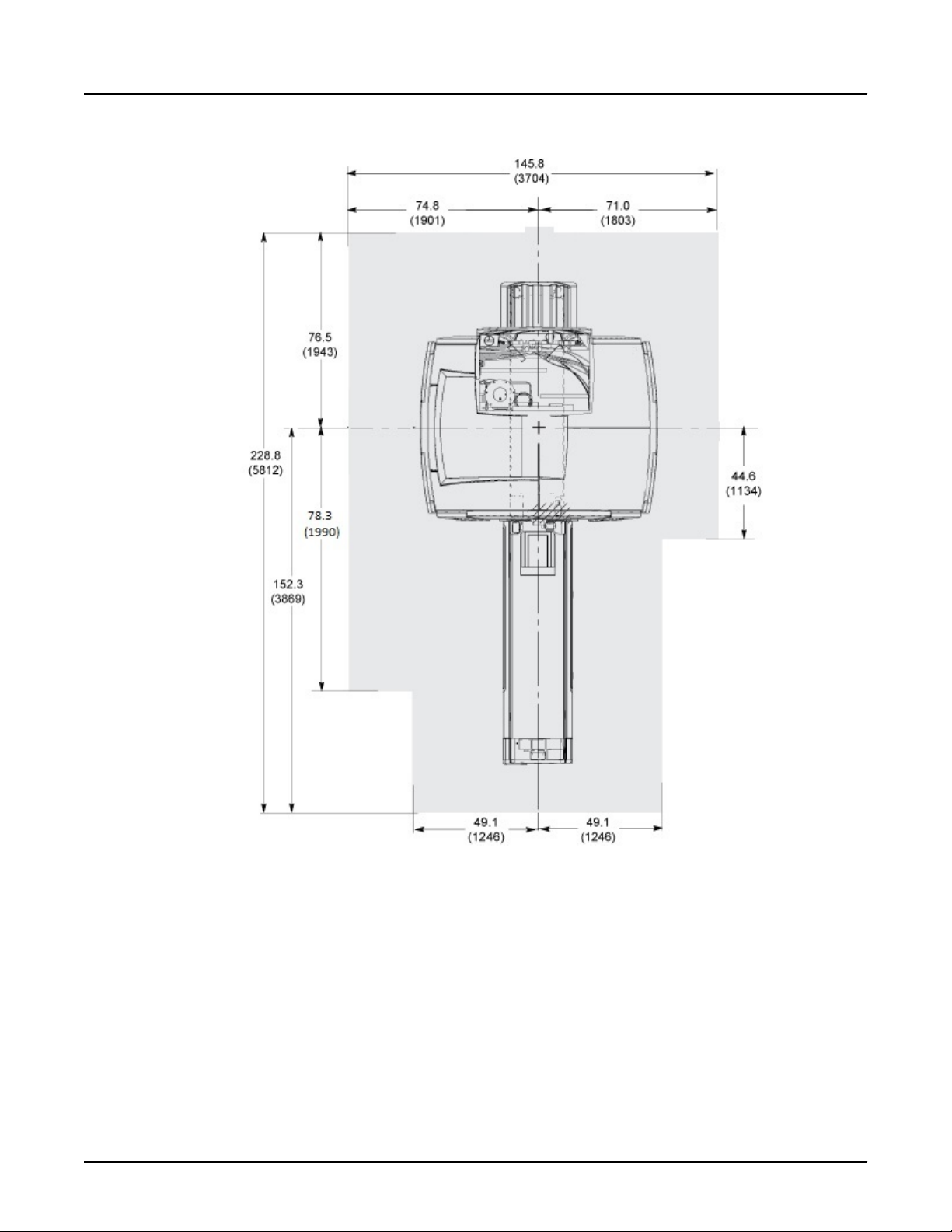
Illustration 2-2: Minimum Magnet Service Area (Top View)
NOTE: 1. All dimensions are in inches; bracketed dimensions are in millimeters
2. Shaded area indicates minimum service area
Chapter 2 General System Level 25

SIGNA Voyager Pre-Installation
Direction 5680008–1EN, Revision 2
Illustration 2-3: Minimum Magnet Ceiling Height (Top View)
NOTE:
1. All dimensions are in inches; bracketed dimensions are in millimeters
2. Shaded area indicates floor to ceiling minimum height of 98.5 (2500)
26 2 MR Suite Minimum Room Size Requirement
3 IEC EMC Compliance
Per IEC 60601-1-2 Medical Electrical Equipment requires special precautions regarding
Electromagnetic Compatibility (EMC) and must be installed and put into service according to the
EMC information provided in the following tables. Full declaration is stored on-site in the user
manual delivered with the system.
The MR system is designed and tested to the following standards:
Table 2-2: Guidance And Manufacturer’s Declaration – Electromagnetic Emissions
The system is intended for use in the electromagnetic environment specified below. The customer or the user of the system should
assure that it is used in such an environment.
Emissions Test Compliance Electromagnetic Environment – Guidance
RF Emissions CISPR 11 Group 2 The system must emit electromagnetic energy in order to perform its
RF Emissions CISPR 11 Class A The system is suitable for use in all establishments other than domestic
Table 2-3: Guidance And Manufacturer’s Declaration – Electromagnetic Immunity
SIGNA Voyager Pre-Installation
Direction 5680008–1EN, Revision 2
intended function. Nearby electronic equipment may be affected
and those directly connected to the public low-voltage power supply
network that supplies buildings used for domestic purposes
The system is intended for use in the electromagnetic environment specified below. The customer or the user of the system should
assure that it is used in such an environment.
Immunity test IEC 60601 test level Compliance Level
Electrostatic discharge (ESD) IEC
61000-4-2
Electrical fast transient / burst IEC
61000-4-4
Surge IEC 61000-4-5 ±1 kV line(s) to line(s) ±1 kV differential mode
Voltage dips, short interruptions and volt‐
age variations on power supply input
lines IEC 61000-4-11
Power Frequency (50/60Hz) magnetic
field IEC 61000-4-8
Conducted RF IEC 61000-4-6 3 Vrms 150 kHz to 80 MHz 3 Vrms
Radiated RF IEC 61000-4-3 3 V/m 80 MHz to 2,5 GHz 3 V/m
±6 kV contact ±6 kV contact
±8 kV air ±8 kV air
±2 kV for power supply lines ±2 kV for power supply lines
±1 kV for input/output lines ±1 kV for input/output lines
±2 kV line(s) to earth ±2 kV common mode
<5 % UT (>95 % dip in UT) for 5 sec.
3 A/m 3 A/m
<5 % UT (>95 % dip in UT) for 5 sec.
Chapter 2 General System Level 27

4 MR Seismic Requirements
Contact the Project Manager of Installation for any questions regarding MR system seismic
requirements or specifications.
The customer is responsible for seismic anchoring of GE components
1.
Center of gravity, weight, physical dimensions, and attachment points are provided for
2.
seismic calculations.
SIGNA Voyager Pre-Installation
Direction 5680008–1EN, Revision 2
28 4 MR Seismic Requirements
5 MR Suite Acoustic Specifications
The following table lists the acoustic output of GE Healthcare equipment:
Table 2-4: Acoustic Specifications (Under Ambient Conditions)
SIGNA Voyager Pre-Installation
Direction 5680008–1EN, Revision 2
GE Equipment Acoustic Output
Control Room ≦ 80dBA 20 to 20k Hz
Equipment Room ≦ 80dBA 20 to 20k Hz
Magnet Room
Frequency
Refer to Acoustic Background and Design Guidelines for guidance to contain the noise within
the magnet room .
NOTE:
All GE equipment acoustic output values are for base equipment configuration in each
room.
Chapter 2 General System Level 29

6 MR Suite Magnetic Field Specifications
6.1 Magnet Fringe Field
Illustration 2-4, Illustration 2-5, Illustration 2-6 are the fringe field plots for the 1.5T LCC RD
Magnet. These plots illustrate the three-dimensional area of magnetic field without the influence
of any nearby ferrous objects or the earth's ambient magnetic field. Actual magnetic field
intensity at given locations will vary from these plots due to the following effects:
Ferrous materials used in building construction which will become permanently magnetized
•
when in close proximity to the MR generated magnetic field.
Earth's magnetic field - about 0.5 gauss in strength and unidirectional.
•
Therefore, these plots are only approximations of actual field intensities found at points
surrounding the magnet. These plots should be used as an aid in reviewing the location of MR
and hospital equipment and services (i.e. elevators, vehicular traffic, computer monitors, etc.).
Refer to Proximity Limits for the sensitivities of various equipment within the magnetic field.
Potential Exists Under fault conditions that the 5 gauss line may expand to 19.86 ft (6.0m)
Radially and 24.60ft (7.5m) axially for 2 seconds or less.
SIGNA Voyager Pre-Installation
Direction 5680008–1EN, Revision 2
30 6 MR Suite Magnetic Field Specifications

SIGNA Voyager Pre-Installation
Direction 5680008–1EN, Revision 2
Illustration 2-4: 1.5 Tesla LCC RD Magnetic Isogauss Line Plot - Top View
Chapter 2 General System Level 31

SIGNA Voyager Pre-Installation
Direction 5680008–1EN, Revision 2
Illustration 2-5: 1.5 Tesla LCC RD Magnetic Isogauss Line Plot - Front View
32 6 MR Suite Magnetic Field Specifications

SIGNA Voyager Pre-Installation
Direction 5680008–1EN, Revision 2
Illustration 2-6: 1.5 Tesla LCC RD Magnetic Isogauss Line Plot - Side View
6.2 Interference from Changing Magnetic Fields
Metal objects moving within the magnet sensitivity lines can produce a field disturbance during
clinical imaging. If the metal object is moving it will produce a fluctuating dipole type of field
which cause image artifacts. As an example, a car driven inside the moving metal line will act as
a dipole and produce a time varying field which change the magnet's main field during the
imaging time. The same vehicle may park within the moving metal line and remain parked
during clinical scanning without impact to the main field. See Illustration 2-7 and Illustration 2-8 .
Chapter 2 General System Level 33

SIGNA Voyager Pre-Installation
Direction 5680008–1EN, Revision 2
Illustration 2-7: Magnet Moving Metal Sensitivity Line Plot (Side View)
Illustration 2-8: Magnet Moving Metal Sensitivity Line Plot (Top View)
34 6 MR Suite Magnetic Field Specifications

Table 2-5: Magnet Moving Metal Requirements
SIGNA Voyager Pre-Installation
Direction 5680008–1EN, Revision 2
Steel Objects Category Definition Of Distance Location Minimum Distance Radial X Axial ft (m)
Objects 100 - 400 lbs distance from isocenter radial x axial (See Note 1) 3 Gauss line
Cars, Minivans, Vans, Pickup Trucks,
Ambulances
Bus, Trucks (Utility, Dump, Semi) distance from isocenter measured to center of driving or
Objects > 400 lbs, Elevators, Trains,
Subways
Notes
1. Radial distances are magnet X and Y axis. Axial distances are magnet Z axis.
EXAMPLE: For Moving Metal Requirements of objects > 400 lbs category you can use the time history of the occurrence to determine
2.
what milligauss level to use.
a. If the site has elevators/counter weights near the magnet and the elevator can stop on the floors for longer than 20 seconds (which
is usually the case), peak-to-peak milligauss reading must be less than 4.43.
If the site has a subway nearby and the field disturbance is less than 5 seconds, the peak-to-peak milligauss reading must be less
b.
than 8.39.
c. Use 4.43 milligauss peak-to-peak.
distance from isocenter measured to center of driving or
parking lane radial x axial (See Note 1)
parking lane radial x axial (See Note 1)
Place a directional probe (e.g. flux gate sensor) at isocen‐
ter of proposed magnet location aligned along the Z-axis.
Measure p-p magnetic field change (dc).
See Illustration 2-9 and see Example in
See Note 1
15.5 x 21 (4.72 x 6.40)
18.1 x 24.5 (5.52 x 7.47)
Note 2
Chapter 2 General System Level 35

SIGNA Voyager Pre-Installation
Direction 5680008–1EN, Revision 2
Illustration 2-9: Actual Axial Shielding Performance
6.3 Electrical Current
1. Electrical current in high voltage power lines, transformers, motors, or generators near the
magnet may affect magnetic field homogeneity
36 6 MR Suite Magnetic Field Specifications

SIGNA Voyager Pre-Installation
Direction 5680008–1EN, Revision 2
2. Magnetic field interference at 50 or 60 Hz must not exceed 40 milligauss RMS respectively
at the magnet location (refer to Illustration 2-10)
The following equation can be used as a general guide in determining allowable current in
3.
feeder lines at a given distance from the magnet isocenter:
a.
For 1.5T LCC RD Magnet: I= (20X2)/S
I = Maximum allowable RMS single phase current (in amps) or maximum allowable RMS
b.
line current (in amps) in three phase feeder lines
c. S = Separation (in meters) between single phase conductors or greatest separation
between three phase conductors
d. X = Minimum distance (in meters) from the feeder lines to isocenter of the magnet
Illustration 2-10: Magnet Allowable Milligauss vs. Line Frequency for AC Equipment
Refer to Chapter 7, Sample Calculation AC Power Equipment Minimum Distance for additional
examples.
6.4 Non-MR System Equipment Sensitivity to Magnetic Fields
This section lists equipment known to be sensitive to high magnetic fields. Recommended limits
given are based on general MR site planning guidelines. Actual susceptibility of specific devices
Chapter 2 General System Level 37

SIGNA Voyager Pre-Installation
Direction 5680008–1EN, Revision 2
may vary significantly depending on electrical design, orientation of the device relative to the
magnetic field, and the degree of interference considered unacceptable.
Site plans must include consideration for magnetic field interaction with all customer equipment.
Use the table for reference only. The gauss limits in the table are approximate for that type of
equipment. Refer to OEM manuals for the equipment at your site to determine the actual Gauss
limits.
Table 2-6: Magnetic Proximity Limits
Gauss (mT) Limit Equipment
0.5 gauss (0.05mT) Nuclear camera
1 gauss (0.1mT) Positron Emission Tomography scanner Video display (tube)
Linear Accelerator CT scanner
Cyclotrons Ultrasound
Accurate measuring scale Lithotriptor
Image intensifiers Electron microscope
Bone Densitometers
3 gauss (0.3mT) Power transformers Main electrical distribution transformers
5 gauss (0.5mT) Cardiac pacemakers Biostimulation devices
Neurostimulators
10 gauss (1mT) Magnetic computer media Telephone switching stations
Hard copy imagers Water cooling equipment
Line printers HVAC equipment
Video Cassette Recorder (VCR) Major mechanical equipment room
Film processor Credit cards, watches, and clocks
X-ray tubes
Large steel equipment, including:
Emergency generators Air conditioning equipment
Commercial laundry equipment Fuel storage tanks
Food preparation area Motors greater than 5 horsepower
50 gauss (5mT) Metal detector for screening Telephones
LCD panels
No Limit Digital Detectors
6.5 Magnet Shield
NOTICE
If a site has an existing magnetic shield and an upgrade to the LCC RD magnet
is being performed, the existing shield must be evaluated by the GE Healthcare
MR Siting And Shielding Group.
Magnetic shielding is used to reduce the fringe field around the magnet. Refer to Section 6.1 for
the fringe field plots for the Magnet.
38 6 MR Suite Magnetic Field Specifications

SIGNA Voyager Pre-Installation
Direction 5680008–1EN, Revision 2
Magnetic shielding can also be used to reduce the magnetic field disturbance from moving
metal objects which can improve the moving metal capability.
Room magnetic shielding generally consists of iron plates in the room walls, floor, and ceiling.
Special consideration should be given when selecting a magnet site location due to the expense
and effort required to provide magnetic shielding.
Designing a magnetic shield requires a comprehensive computer analysis which predicts the
effect the shield will have on the magnetic field as well as the effect of the shield on the
homogeneity of the magnet. The structural capacity of the site and space availability are
important factors in the design of the shield. The GE Healthcare MR Siting & Shielding Group
has the capability to design magnetic shields which meet a broad range of site requirements.
Chapter 2 General System Level 39

7 Multiple MR System Requirements
7.1 Multiple Magnets
When installing multiple magnets, the 3 gauss lines must not intersect or the magnets will be
interactive. Contact the GE Healthcare Project Manager of Installation (PMI) for any questions
regarding magnetic field interaction.
Illustration 2-11: Two Magnet Installation
SIGNA Voyager Pre-Installation
Direction 5680008–1EN, Revision 2
40 7 Multiple MR System Requirements

7.2 Shared Equipment Rooms
When installing multiple MR systems in a shared equipment room, the following conditions must
be met:
The other system’s cabinet with RF amp must be separated from ISC by at least 79 in.
1.
(2000 mm).
2. The other system’s Penetration panel must be separated from Penetration Wall of ISC by at
least 118 in (3000 mm).
Cables from different MR systems must not be routed together
3.
SIGNA Voyager Pre-Installation
Direction 5680008–1EN, Revision 2
Chapter 2 General System Level 41

8 MR Suite Temperature and Humidity
CAUTION
Equipment Failure
Failure to maintain the required temperature or humidity at all times (i.e., both
working and non-working hours) may result in equipment failure, scanning failure,
or warranty void.
Ensure the HVAC system has the correct capacity for the room size, equipment
heat output, and environmental conditions to maintain proper temperature and
humidity.
This section provides temperature and humidity requirements for the MR suite. Specific
construction requirements for each room can be found in the following sections:
Magnet Room
•
Equipment Room
•
Operator Room
•
SIGNA Voyager Pre-Installation
Direction 5680008–1EN, Revision 2
8.1 Temperature and Humidity Requirements
Table 2-7: Room Temperature and Humidity Requirements
Room
Equipment Room (at Inlet to Equip‐
ment)
Magnet Room 59-69.8 (15-21) 5 (3) 30-60 5
Operator Room 59-89.6 (15-32) 5 (3) 30-75 5
Notes:
1. Operating temperature gradient limits shall be between -5° F/Hr (-3° C/Hr) and 5° F/Hr (3° C/Hr), when averaged over 1 hour
Operating humidity gradient limits shall be between -5% RH/hour and 5% RH/hour, when averaged over 1 hour
2.
Maximum ambient temperature is derated by 1 degree C per 300 m above 2000 m (not to exceed 2600 m)
3.
Range °F (°C)
59-89.6 (15-32)
1. The customer is responsible for HVAC system design, purchase, and installation
The temperature requirements must not be exceeded at any point during the day (both
2.
working or non-working hours)
3. A separate thermostat must be provided for the Magnet room
Temperature Humidity
Change °F/Hr (°C/Hr)
3
5 (3) 30-75 5
1
Range %RH
Change %RH/Hr
2
42 8 MR Suite Temperature and Humidity

8.2 Equipment Heat Output Specifications
This section details the heat output for specific components. These heat outputs define the
maximum condition. Actual heat output and room temperature may vary due to environmental
factors, room insulation, actual usage, and any non-GE Healthcare equipment used in the MR
suite. Also, due to large variations in heat loads, the HVAC system may require unloaders, hot
gas bypass, and reheat to maintain humidity levels.
Table 2-8: System Heat Output for Air Cooling
SIGNA Voyager Pre-Installation
Direction 5680008–1EN, Revision 2
Component Magnet Room
Maximum Average
Magnet (MAG) and Patient
Transport Table (PT)
Main Disconnect Panel (MDP,
optional)
Integrated System Cabinet
(ISC)
Heat Exchanger Cabinet (ICC) 3,412
Cryocooler Compressor (CRY)
Magnet Monitor (MON) 205 (60) 205 (60) 205 (60)
Operator Workspace equip‐
ment (OW)
8,189
(2,400)
BTU/hr (W)
4,095
(1,200)
Idle
1,915
(561)
Equipment Room
BTU/hr (W)
Maximum Average
901 (264) 450 (132)
24,232
(7,100)
(1,000)
1,706 (500)
7,270*
(2,130)
1,706*
(500)
1,706
(500)
Idle
450
(132)
955*
(280)
0* (0)
1,706
(500)
Control Room
BTU/hr (W)
Maxi‐
mum
4,947 (1,450)
Aver‐
age Idle
NOTE: For ISC and ICC, Average value is calculated using Standby mode and Idle value is
calculated using Night Mode (Power Off Mode).
Table 2-9: System Options Heat Output for Air Cooling
Component
MR Elastography
Magnet
Room
BTU/hr
(W)
Equipment
Room
BTU/hr (W)
480 (141)
Control
Room
BTU/hr (W)
Chapter 2 General System Level 43

9 MR Coolant Requirements
NOTICE
Equipment Failure. A continuous supply of facility liquid coolant to the Integrated
Cooling Cabinet (ICC) is required at all times for proper system operation. Failure
to provide liquid coolant with the requirements listed in this section may cause
equipment failure.
9.1 Integrated Cooling Cabinet (ICC) Coolant Requirements
1. The facility must provide liquid coolant to the Integrated Cooling Cabinet (ICC)
The facility must provide pipe/hose, filter, and connectors to the ICC
2.
The facility must provide an uninterrupted supply of liquid coolant to the ICC at magnet
3.
delivery
4. The ICC, ISC and CRY must be located on the same level.
5. The customer must provide and install an in-line flow meter on either the supply or return
facility coolant hose. The flow meter must be capable of visually displaying volumetric flow
between 10.5 and 26.4 gpm (40 and 100 L/min) and configured for the properties of the
cooling fluid in use
SIGNA Voyager Pre-Installation
Direction 5680008–1EN, Revision 2
Table 2-10: Facility Liquid Coolant Requirements
Parameter Requirements
Availability Continuous
Antifreeze 0-40% propylene glycol
Minimum Flow 13.2 gpm (50 L/min)
Maximum Flow 21.1 gpm (80 L/min)
Typical Flow 17.2 gpm (65 L/min)
Maximum Pressure Drop in ICC at Mini‐
mum Flow
Maximum Pressure Drop in ICC at Maxi‐
mum Flow
Maximum Inlet Pressure to ICC 80 psi (5.52 bar)
Chiller Size Minimum 36 KW
Condensation Protection Facility Plumbing to the ICC must be properly routed and insulated to prevent equipment damage or safety
Minimum Continuous Heat Load 7.5 KW
Inlet Temperature 41 to 59°F (5 to 15°C) measured at the inlet to the ICC
Customer supplied feeder hose (from
main water supply to ICC)
26.1 psi (1.8 bar) with 40% propylene glycol-water; 1021 kg/m3 density
49.3 psi (3.4 bar) with 40% propylene glycol-water; 1021 kg/m3 density
hazards
1 inch (25.4 mm) minimum hose inside diameter
If Hose length is over 10m less than 30m, it is recommended to use 1.25 inch (31.75 mm) minimum hose in‐
side diameter. If using 1.25 inch (31.75 mm) hose, prepare adapter to reduce inner diameter to 1 inch (25.4
mm) for ICC connection
44 9 MR Coolant Requirements

Table 2-11: Facility Water Quality Requirements
pH Value 6.5 to 8.2 at 77 °F (25 °C)
Electrical Conductivity < 0.8 mmho/cm
Chloride Ion < 200 ppm
Sulfate Ion < 200 ppm
M-Alkalinity < 100 ppm
Total Hardness < 200 ppm
Calcium Hardness < 150 ppm
Ionic Silica < 50 ppm
Iron < 1.0 ppm
Copper < 0.3 ppm
Sulfide Ion None, not detectable
Ammonium Ion < 1.0 ppm
Residual Chlorine < 0.3 ppm
Free Carbon Dioxide < 4.0 ppm
Stability Index 6.0 to 7.0
Suspended Matter < 10 ppm
Particle Size < 100 micron (with field changeable filter)
SIGNA Voyager Pre-Installation
Direction 5680008–1EN, Revision 2
Chapter 2 General System Level 45

SIGNA Voyager Pre-Installation
Direction 5680008–1EN, Revision 2
Illustration 2-12: MR System Water Cooling Block Diagram
46 9 MR Coolant Requirements

9.2 Emergency Facility Coolant Requirements
The facility may provide an optional backup coolant supply:
Cryocooler operation only: Backup coolant may be routed to ICC backup water port for the
Cryocooler compressor with the following requirements:
The facility is responsible for coolant, 1/2” pipe/hose, filters, and connectors to supply the
1.
coolant to the ICC back up port for the CRY.
The emergency coolant to Cryocooler Compressor must be drained to the facility through
2.
customer supplied 1/2” hose and must not back-feed to the ICC
3. Coolant must meet all other ICC coolant requirements listed in and Table 2-11
4. The charts in Illustration 2-13 shows the coolant flow rate and temperature requirements for
the Cryocooler Compressor:
SIGNA Voyager Pre-Installation
Direction 5680008–1EN, Revision 2
Chapter 2 General System Level 47

SIGNA Voyager Pre-Installation
Direction 5680008–1EN, Revision 2
Illustration 2-13: Cryocooler Water Cooling Requirements
48 9 MR Coolant Requirements

10 MR Suite Electrical Requirements
10.1 General Electrical Requirements
1. Customer is required to install a Main Disconnect Panel (MDP).
NOTE: GE MDP is orderable OR the customer can procure their own.
Refer to Section 10.2 for MDP Design Requirements
a.
Refer to Illustration 2-14 for Main Disconnect Panel (MDP) Set-Up
b.
2. The facility must provide system power to the MDP
3. All associated transformers and cables must be correctly sized for system power
requirements
4. The facility must provide cabling from the MDP to the PDU in Integrated System Cabinet
and from the MDP to the Cryocooler Compressor (F-50) in Integrated Cooling Cabinet (ICC)
5. For the power of facility backup cooling and compressor, it is customer’s responsibility to
prepare.
SIGNA Voyager Pre-Installation
Direction 5680008–1EN, Revision 2
Table 2-12: Facility Power Requirements
Component Parameter Requirements
At Main Dis‐
connect Pan‐
el (MDP)
Voltage / Frequency
Daily Voltage Variation Customer to provide +7.5% / -10% from nominal at MDP input under all line and load
Phase
Phase Balance Difference between the highest phase line-to-line voltage and the lowest phase line-
Power Quality Recommended THD of less than 2.5%
Facility Zero Voltage
Reference Ground
480 VAC 60 ±3 Hz
415 VAC 50 ±3 Hz, 60 ±3 Hz
400 VAC 50 ±3 Hz, 60 ±3 Hz
380 VAC 50 ±3 Hz, 60 ±3 Hz
conditions. This includes variation of power source and transmission losses up to the
MDP.
Input power to the MDP may use one of the following configurations:
A 3 phase solidly grounded WYE with Ground (4-wire system)
•
If a neutral wire exists, it must be terminated prior to or inside the MDP
A 3 phase floating DELTA with Ground (4-wire). Do not connect a corner
•
grounded DELTA source
Note: Some UPS options may require a neutral (refer to manufacturer documentation
for requirements).
to-line voltage must not exceed 2%
The facility ground for the MR system must originate at the system power source
•
(i.e., transformer or first access point of power into the facility) and be continu‐
ous to the MR system Main Disconnect Panel (MDP) in the room.
Main facility ground conductor to Main Disconnect Panel (MDP) must be appro‐
•
priately sized insulated copper wire.
The main facility ground to the Main Disconnect Panel (MDP) must meet local
•
codes.
Chapter 2 General System Level 49

SIGNA Voyager Pre-Installation
Direction 5680008–1EN, Revision 2
Component Parameter Requirements
Service re‐
ceptacle in
Magnet
Room
Power Availability Continuous, facility power is required at all times for operation of the Cryocooler
Voltage / Frequency
Phase 1
Maximum Amps 2.0
(CRY) to minimize cryogen consumption.
100-120 VAC 50/60 Hz Receptacle required for small power tools. Local volt‐
age and portable transformers for voltage values.
Table 2-13: System Power Demand
Equipment Power Draw (kVA)
ISC PDU Continuous Power 55
ISC PDU 5 Second Power 65
Cryo Compressor Continuous Power 9
Total System 5 Second Power 77
Total system Continuous Power 64
Standby Consumption (no scan) (PDU, CRY) < 17
Table 2-14: Power Consumption
Power Consumption Sleep Mode 5.7kW
Power Consumption Standby(no scan) 11.1kW
Power Consumption Typical consumption 16.1kW
50 10 MR Suite Electrical Requirements

SIGNA Voyager Pre-Installation
Direction 5680008–1EN, Revision 2
Illustration 2-14: Main Disconnect Panel (MDP) Set-Up
Chapter 2 General System Level 51

10.2 Main Disconnect Panel (MDP) Requirements
WARNING
PERSONNEL INJURY OR EQUIPMENT DAMAGE
CUSTOMER SUPPLIED MDP MUST HAVE CORRECTLY SIZED WIRES AND
RATED COMPONENTS TO MEET THE MR SYSTEM POWER
REQUIREMENTS.
WARNING
PERSONNEL INJURY OR EQUIPMENT DAMAGE
IF THE MDP POWERS THE CRYO COMPRESSOR, THE MDP EMERGENCYOFF FUNCTION MUST DISABLE THE AUTO RESTART FUNCTIONALITY
WHEN ACTUATED.
1. MDP to provide Auto-Restart. Auto-Restart to provide power to the Cryo compressor. See
Table 2-13
2. Manual Restart Capability
a. A low voltage release feature to disconnect the PDU upon power loss
SIGNA Voyager Pre-Installation
Direction 5680008–1EN, Revision 2
The PDU circuit must require a manual restart when power is reapplied to the main
b.
panel
3. Emergency Off Circuit
a. The MDP must have an emergency off control circuit that disables power to the entire
MR system
The emergency off circuit must be actuated by remotely located push button(s) (see
b.
Illustration 2-14)
c. The wire size for the emergency-off circuit is 12–22 AWG and is supplied by the
customer.
The manual reset must be required to restore power to the entire system
d.
e. Two sets of isolated, normally closed contacts that open when an emergency off button
is actuated must be provided for optional accessories
4. Lock-out/Tag-out
a. The MDP break must have capability to lock-out for single point Lock-out/Tag-out
requirements
A standard sized hasp for lock-out
b.
5. The MDP must be marked as required by national/local regulations
6. The MDP must provide terminations for all grounds entering, leaving and residing within the
panel
7. The MDP must provide terminations of appropriate size for all power wiring entering and
leaving the panel
Terminal blocks that can accept 3/0 AWG or larger on the main panel
a.
52 10 MR Suite Electrical Requirements

SIGNA Voyager Pre-Installation
Direction 5680008–1EN, Revision 2
b. Terminal blocks to accept 12 AWG (E0009) on the Cryocooler
c. Terminal blocks to accept 1 or 2 AWG on the PDU in ISC
The optional GE Healthcare MDP consists of the following:
8.
a.
A 3-pole 200A main circuit breaker rated for the total current of all the sub-breaker
circuits
A 3-pole 150A circuit breaker rated for the current of the PDU circuit
b.
A Customer Supplied 3-pole 30A circuit breaker is required for Cryocooler circuit outside
c.
of MDP
d. All circuit breakers have a short circuit current interrupting rating of 25000 Amps
Auto restart on the Cryocooler circuit
e.
f. Emergency off circuit including 2 pushbuttons to be installed external to the MDP
g. Terminal blocks that can accept 3/0 AWG maximum size on the main, 8 AWG maximum
size on the 30A Customer Supplied Breaker for Cryocooler circuit, and 1 or 2 AWG on
the PDU in ISC.
NOTE:
12 AWG (Cable RUN # E0009) will be connected between the 30A Customer
Supplied Breaker and the Cryocooler.
h. Isolated neutral terminal block for termination
i. Multiple ground terminal blocks as required by panel design
Listed and labeled by a Nationally Recognized Testing Lab (NRTL) in accordance with
j.
UL 508A and IEC/EN 60204–1 and bear the CE Marking in accordance with the EU Low
Voltage Directive (2006/95/EC) and Electromagnetic Compatibility Directive (2004/108/
ED).
Power on indicators
k.
l. Two isolated, normally open contact pairs that open when e-OFF is pressed for use with
optional accessories
Chapter 2 General System Level 53

11 MR System Shipping and Receiving
NOTICE
All shipping dimensions and weights are approximate and may vary based on
ship-to location, required rigging, or other requirements. Some shipping or
access routes may have requirements in addition to those listed in this section.
Contact the GE Healthcare Project Manager of Installation (PMI) to verify magnet
shipping, rigging, and access.
11.1 Receiving Requirements
1. The customer must provide an area for unloading system components from the truck and
delivering to the MR suite
SIGNA Voyager Pre-Installation
Direction 5680008–1EN, Revision 2
NOTE:
Contact the GE Healthcare Project Manager of Installation (PMI) for a list of
experienced rigging companies.
2. The customer is responsible for ensuring:
a.
All floors along the route will support the weight of the magnet (GE Healthcare
recommends a structural analysis)
Doors or other openings are sufficiently wide to allow passage
b.
Sufficient room is provided for any required rigging tools
c.
11.2 Facility Delivery Route Requirements
The following table lists the delivery dimensions of system components. The delivery route must
be planned to accommodate the dimensions listed.
Table 2-15: Delivery Route Requirements
Component
Magnet See Magnet shipping dimensions Table 2-16
Cryogen Dimensions vary depending on dewar type used. Verify with cryogen supplier.
ISC Cabinet See ISC dimensions in ISC Cabinets are moved with
ICC Cabinet
Width Depth Height Weight
in mm in mm in mm lbs kg
See ICC dimensions in ICC
Notes
casters attached under the
base of each cabinet.
54 11 MR System Shipping and Receiving

11.3 MR System Component Shipping Specifications
MR system component shipping dimensions and weight are listed below:
Table 2-16: MR System Component Shipping Specifications
SIGNA Voyager Pre-Installation
Direction 5680008–1EN, Revision 2
MR Component
1.5T LCC RD Magnet 89 x 94 x 93 2252 x 2400 x 2363 See Note 1 Domestic - Tarped International -
Magnet Accessory Equip‐
ment
VibroAcoustic Damping
Kit
Cryocooler Compressor 26 x 28 x 42 660 x 711 x 1067 275 125 Pallet with box cover
Enclosure TBD TBD TBD TBD Box on a pallet
Patient Table 104 x 38 x 35 2650 x 960 x 880 901 408.5 Pallet
Integrated System Cabi‐
net (ISC)
Integrated Cooling Cabi‐
net (ICC)
SPT Phantom Set 34 x 32.5 x
Operator Workspace Cab‐
inet
Operator Workspace Dis‐
play
Operator Workspace Ta‐
ble
Notes: 1. Approximate magnet shipping weight of magnet with cryogens, VRMw Gradient & RF coils, Enclosure parts installed on magnet,
and lifting beams (i.e. minus packaging material): 11,800 lbs (5352 kg). International shipments must add shipping crate/pallet of 2,200 lbs
(998 kg).
in. mm lbs kg
48 x 48 x 28 1219 x 1219 x 711 400 182 Crate
36 x 65 x 12 914 x 1651 x305 575 261 Box on pallet
64 x 51 x 89 1620 x 1290 x 2250 2,665 1,209 Box
37 x 44 x 86 932 x 1118 x 2188 1069 485 Box
60
24 x 35 x 31 600 x 900 x 780 243 110 Wood pallet with cardboard cover
27 x 33 x 27 686 x 838 x 686 125 57 Pallet
45 x 54 x 37 1143 x 1372 x 940 180 82 Box
W x D x H Weight
Notes
crate/pallet
864 x 826 x 1524 350 159 On cart casters with box cover
Chapter 2 General System Level 55

SIGNA Voyager Pre-Installation
Direction 5680008–1EN, Revision 2
Illustration 2-15: Magnet Dimensions (as Shipped)
NOTE:
Dimensions are in inches. Bracketed dimensions are in millimeters.
Table 2-17: MR System Component Replacement Shipping Specifications
Component
Replacement RF Body Coil 30 x 30 x 60 762 x 762 x 1524 255 116 Replacement coil is shipped in a pro‐
Replacement VRMw Gradient
Coil Assembly on a Shipping
Cradle/Cart
Gradient Coil Replacement
Tool Kit Crate
Note:
The replacement Gradient Coil Assembly weight is approximately 2205 lbs (1000 kg), the shipping cradle is 132 lbs (60 kg), and the Gradient
Coil Assembly shipping/installation cart weighs 855 lbs (389 kg). The coil assembly outside diameter x length dimensions are 35.7 x 57.2 in.
(908 x 1452 mm).
39 x 99.84 x
59 See Note
30 x 86 x 30 762 x 2184 x 762 750 340 This crate box includes Gradient In‐
W x D x H Weight
Notes
in. mm lbs kg
tective case. Weight & dimensions
are for coil & case.
991 x 2536 x 1499 3194 1449 Initial Gradient Coil Assembly is ship‐
ped installed in the Magnet. Shipping/
installation cart is used to install re‐
placement coil assembly only.
sertion Kit
56 11 MR System Shipping and Receiving

SIGNA Voyager Pre-Installation
Direction 5680008–1EN, Revision 2
Illustration 2-16: Gradient Coil Cart
NOTE: Dimensions are in inches. Bracketed dimensions are in millimeters.
Chapter 2 General System Level 57

This page left intentionally blank.
SIGNA Voyager Pre-Installation
Direction 5680008–1EN, Revision 2
58 11 MR System Shipping and Receiving

Chapter 3 Magnet Room
1 Magnet Room Introduction
The Magnet Room is best understood as a series of layers, or “rooms within a room.” Each of
these rooms has a specific function and associated requirements. All requirements in this
chapter must be followed to ensure safe and proper operation of the MR system.
1. The Magnetic shielded room contains the MR Magnet fringe field within a confined space. A
site survey is required to determine magnet shield requirements (not all sites require
magnetic shielding). Because of the added cost of magnetic shielding, room location should
be carefully considered.
2. The Acoustic room is a layer used to help attenuate the noise produced during a scan. An
acoustic engineer is strongly recommended to assess the environment.
3. The RF Shielded room is critical to the proper MR system operation. RF shielding prevents
interaction of external RF radiation with MR system operation and it also prevents MR
system RF radiation from interfering with external systems, such as aircraft control. Special
care must be used when installing all fixtures penetrating the RF shield (e.g., vents,
electrical conduit, penetration panels) to ensure the integrity of the RF shield is maintained.
SIGNA Voyager Pre-Installation
Direction 5680008–1EN, Revision 2
4. The Finished room includes the wall coverings, ceiling tile, ceiling grid, other fixtures,
Magnet (MAG) and Patient Table (PT). When planning the finished room, ensure the
following:
All building codes are met (such as maintaining egress routes)
a.
b. Items which may generate or create RF interference (including florescence lighting) are
not allowed for installation within the Magnet room
c. Customer is responsible for the selection and installation of all locally required safety
devices (e.g., smoke detectors, oxygen monitors, etc.)
Ferrous or metallic items which could become projectiles when the magnet is installed
d.
(including wall coverings, ceiling tile, ceiling grid, or other fixtures) are not used or
properly secured
Chapter 3 Magnet Room 59

Direction 5680008–1EN, Revision 2
Illustration 3-1: Magnet Room Layers
SIGNA Voyager Pre-Installation
60 1 Magnet Room Introduction

2 Magnet Room Structural Requirements
This section lists the structural requirements that must be considered when performing site
evaluation and planning of the Magnet room.
2.1 Overview
1. When preparing a building plan or evaluating a potential site for an MR system, care should
be taken to ensure the MR suite will not interact with the surrounding environment (i.e.,
magnetic, acoustic, environmental steel, and vibration)
2. The customer is responsible for vibration testing required to verify suitability of a proposed
site. All test results and any questions regarding testing, results, or analysis must be
forwarded to the GE Healthcare Project Manager of Installation (PMI)
2.2 Environmental Steel Limits
A static magnetic field extends in a three-dimensional space around the magnet isocenter.
Environmental steel within the static magnetic field affects the uniformity (or homogeneity) of the
field. Field uniformity is critical to image quality. An analysis of the environmental steel is
required within a 5 feet (1.524 meters) spherical radius of the magnet isocenter. Environmental
steel includes ferrous pipes, beams, concrete rebar, metal decking, existing or proposed RF/
magnetic shielding or shim plates, or any other structural steel in the floors, walls or ceiling.
These items must be limited per Table 3-1 which defines the limits of use as a guideline to help
the customer understand allowable amounts of ferrous rebar, steel decking, or other
components as they design the MR suite and magnet room floor structure. The customer must
provide detail defining ferrous material below the magnet to the Project Manager so the GE
Healthcare MR Siting and Shielding team can review for compliance.
SIGNA Voyager Pre-Installation
Direction 5680008–1EN, Revision 2
Chapter 3 Magnet Room 61

Table 3-1: Steel Mass Limits to Magnet Isocenter
SIGNA Voyager Pre-Installation
Direction 5680008–1EN, Revision 2
Limits Of Steel Mass lbs/ft2 (kg/m2)
0 (0) 0-45 (0-1143) 0-3 (0-76)
2 (9.8) 45-47 (1143-1194) 3-5 (76-127)
3 (14.7) 47-52 (1194-1321) 5-10 (127-254)
8 (39.2) 52-55 (1321-1397) 10-13 (254-330)
20 (98.0) 55+ (1397+) 13+ (330+)
2.3 Vibration Requirements
Excessive vibration can affect MR image quality. Vibration testing must be performed early in
the site planning process to ensure vibration is minimized. Both steady state vibration (exhaust
fans, air conditioners, pumps, etc.) and transient vibrations (traffic, pedestrians, door slamming,
etc.) must be assessed (see Illustration 3-2). Specific requirements for vibration mitigation,
include:
The Magnet (MAG) cannot be directly isolated from vibration. Any vibration issue must be
1.
resolved at the source
MR Suite HVAC must have vibration isolation
2.
3. A vibration analysis must be performed at the proposed site with the results (and any
mitigation) forwarded to the GE Healthcare Project Manager of Installation (PMI). See the
Chapter 7, MR Site Vibration Test Guidelines
Distance From Magnet Isocenter in. (mm) Distance Below Top Surface Of Floor in.
(mm)
4. A transient vibration test must only be performed after a steady-state test has been
performed and all steady-state sources of vibration have been mitigated
5. Transient vibration levels above the specified limits in the Chapter 7, MR Site Vibration Test
Guidelines must be analyzed
6. Any transient vibration that causes vibration to exceed the steady-state level must be
mitigated
7. Vibration test consultant must account for non-mechanically induced signals such as
equipment instabilities, thermal drift or RF interference
62 2 Magnet Room Structural Requirements

SIGNA Voyager Pre-Installation
Direction 5680008–1EN, Revision 2
Illustration 3-2: Magnet Steady State Vibration Specifications
Chapter 3 Magnet Room 63

3 Magnetic Shielded Room Requirements
NOTICE
All sites, including upgrade sites, must be evaluated for magnetic shielding
requirements. Existing magnetic shielding at an upgrade site may not be
sufficient for the new system. Contact the GE Healthcare Project Manager of
Installation (PMI) to request a site evaluation.
Magnetic shielding prevents interaction between the magnet and nearby sensitive devices.
Because of the added cost of magnetic shielding, room location should be carefully considered
(not all sites require magnetic shielding). See MR Suite Magnetic Field Specifications for
detailed magnetic proximity limit information.
1. The GE Healthcare Project Manager of Installation (PMI) works with the customer to
coordinate the magnetic shielding site evaluation
2. If required, the GE Healthcare Project Manager of Installation (PMI) coordinates the delivery
of the magnetic shielding design
3. The customer is responsible for installation of all magnetic shielding
SIGNA Voyager Pre-Installation
Direction 5680008–1EN, Revision 2
64 3 Magnetic Shielded Room Requirements

4 Acoustic Room Specifications
The acoustic room is a layer used to help contain the noise (within the Magnet Room) which is
produces during clinical scanning. The following information is provided for the acoustic
engineer to design for acoustic noise containment within the Magnet room.
Table 3-2: Acoustic Specifications
SIGNA Voyager Pre-Installation
Direction 5680008–1EN, Revision 2
Magnet Bore Isocenter 127 dBA
Front of Magnet - 800 mm from bore measurement 120 dBA
Notes:
1. Maximum Sound Pressure Levels is defined as the maximum allowable level any MR scanner can produce while protecting
the patient to the IEC 60601-2-33 code.
2. The total energy, SPL, is derived through the log sum of each 1/3 band octave totaling the 127 dBA. That is, the maximum
single 1/3 band is lower than the published values at both the isocenter and at the front of the magnet
Maximum Sound Pressure Level
1
Frequency Range
See Illustration 3-3
Illustration 3-3: Sound Pressure Spectral Distribution (1/3 Band Relative SPL)
NOTE: The MR product clinical operation will generate sound pressure proportional to the
specific clinical application. The entire spectra (envelope) shown above (Illustration
3-3) represents the relative 1/3 band octave sound pressure the MR scanner may
transmit into the air. The acoustic room will best suit the customer when the 127 dBA
proportionally distributed as defined by the Illustration
Refer to Acoustic Background and Design Guidelines for acoustic design information.
Chapter 3 Magnet Room 65

5 RF Shielded Room Requirements
5.1 RF Shielded Room Purpose
The RF shielded room is critical to the proper clinical operation of the MR system. RF shielding
attenuates the external RF electromagnetic fields. Low RF environments present lower risk to
RF impacts to image quality. The RF shielding must also prevent the MR system RF emissions
from interfering RF receiving systems such as other MR systems, aircraft control and
communication systems.
RF shielding requirements consider the current RF environment at the site as well as future
conditions, such as expansion, with the addition or upgrade of multiple MR systems, as well as
changes to the RF environment at the time of installation. The RF shielding requirement also
considers the expected degradation over time from the RF shielded room from corrosion and
use.
The overall RF shielding performance aims to address:
IEC EMC Regulatory Compliance
1.
2. MR Clinical image quality for the life of the product
SIGNA Voyager Pre-Installation
Direction 5680008–1EN, Revision 2
5.2 RF Definitions
Broadband Interference
Broadband interference is caused by electrical discharge within the Magnet room. Potential
sources of interference can be reduced by limiting static discharge, ensuring all metal-to-metal
contact is tight and secure, and ensuring all electrical and grounding requirements are met.
Discrete Interference
Discrete interference is fixed-frequency, narrowband RF noise. Potential sources of discrete
interference are radio station transmitters and mobile RF transmitting devices. Magnet room RF
shielding prevents external RF energy from entering the room and degrading the MR system RF
receivers.
Electromagnetic Environment
The totality of electromagnetic phenomena existing at a given location.
Plane Wave
An electromagnetic wave which predominates in the far-field region from an antenna (or
source), and with a wave front which is essentially a flat plane.
Penetration
The passage through a partition or wall of an equipment or enclosure by a wire, cable, pipe,
waveguide, or other conductive object.
Shield
A housing, screen, or cover which substantially reduces the coupling of electric and magnetic
fields into or out of circuits or prevents the accidental contact of objects or persons with parts or
components operating at hazardous voltage levels.
66 5 RF Shielded Room Requirements

Shielding Enclosure (Faraday Cage)
An area (box, room, or building) specifically designed to attenuate electromagnetic radiation, or
electromagnetic radiation and acoustical emanations, originating either inside or outside the
area.
Shielding Effectiveness (SE)
A measure of the reduction or attenuation in the electromagnetic field strength at a point in
space caused by the insertion of a shield between the source and that point.
Primary Ground
All RF Shield components (walls, floor, ceiling, etc) must be electrically bonded together to form
one common ground plane which is connected to the Facility Grounding Conductor
Secondary Ground
Other grounds that connect the outside of the RF Shield room to earth grounds are called
secondary grounds
5.3 Customer Responsibilities
The Customer is responsible for:
SIGNA Voyager Pre-Installation
Direction 5680008–1EN, Revision 2
1. The selection of a quality RF shielded room vendor who understands the RF shielding room
purpose described in Section 5.1.
2. Contracting with a RF shielded room vendor to design and install (including installation of
dock anchor) the RF shielded room to meet requirements in Section 5.4.
3. Maintenance and repair of RF shielded room, to include, but not limited to, shielding
effectiveness (SE), door threshold and door seal, pressure equalization vent operation for
the life of the MR System.
NOTE:
On request, the GE Healthcare Project Manager of Installation (PMI) can supply a
•
list of RF shielding room vendors.
The RF shielded room may not be in a temperature or humidity controlled
•
environment, the customer must take local measures to prevent RF shield
effectiveness degradation.
Special care should be used when installing all fixtures penetrating the RF shield
•
(e.g., vents, electrical conduit, penetration panels, etc.) to ensure the integrity of
the RF shielded room is maintained.
Chapter 3 Magnet Room 67

5.4 Requirements
5.4.1 RF Shield Requirements
1. The RF shielded room with installed blank penetration panels shall provide a minimum of
100 dB of shielding effectiveness (SE) for the entire room at the following frequencies:
63.86 MHz +/- 0.5 MHz
a.
51.00 +/- 0.5 MHz
b.
76.60 +/- 0.5 MHz
c.
SIGNA Voyager Pre-Installation
Direction 5680008–1EN, Revision 2
NOTE:
2.
The minimum tests points for shielding effectiveness must be the following locations:
a. Walls
Penetration panels
b.
Doors
c.
d. All windows, including patient viewing window
e. Skylights
Penetration waveguides installed for GE Healthcare and Non-GE Healthcare options
f.
Power filters
g.
The RF shielded room is designed and installed to meet or exceed the 100 dB
○
of SE. Acceptance of lower SE performance is a customer responsibility with
an absolute lower limit of 90 dB. The Customer must recognize the risk to
accepting a lower quality RF shielded room. The RF shielded room
performance degrades over time. Accepting a RF shielded room of low
performance will result in additional cost to the customer on repairs after room
construction is complete impacting clinical use of the product.
The final shielding effectiveness performance of the RF shielded room is
○
determined based on the lowest measurement of all test point locations.
Chapter 7, RF Shielding Effectiveness and Ground Isolation Test Methods provides details
3.
for shielding effectiveness measurement based on IEEE Std 299-2006
4. When measuring shielding effectiveness (SE), the following must be installed for the RF
shielded room:
All floor mounting bolts (including dock frame anchor bolt)
a.
RF shielded door(s)
b.
Waveguide penetrations, HVAC, cryogen vents, medical gas lines, system options
c.
(including FUS, MRE, etc.)
d. AC power supplied through low-pass filters
Patient view window, skylights, windows, hatches, etc.
e.
68 5 RF Shielded Room Requirements

SIGNA Voyager Pre-Installation
Direction 5680008–1EN, Revision 2
f. PEN Panel frames and blank penetration panels installed, dimensionally equivalent to
the GE panel and the same mounting hardware to be used with the GE penetration
panels
GE Healthcare Field Engineer must be present during RF SE testing and a test report must
5.
be delivered to the PMI
Shielding Effectiveness (SE) test equipment must be calibrated
6.
NOTE:
7.
The RF shielded room must be isolated from earth ground by more than 1000 ohms DC
resistance during construction (before electrical installation)
8. The RF shielded room must be grounded to the RF common ground stud (which is
grounded back to the Power Distribution Unit in the Power, Gradient, RF cabinet)
See Grounding Requirements for RF Shield room grounding details
RF shielded room installation materials must meet steel mass limits listed in Magnet Room
9.
Structural Requirements to keep magnetic field homogeneity
10. Any moving part (such as doors) must not contain magnetic materials
The calibration cycle of equipment must be no greater than 2 years.
5.4.2 RF Shield Test Report
A test report must be prepared by the testing organization performing the shielding
effectiveness and ground isolation resistance tests for the RF shielded room. The test report
includes data necessary for the evaluation of the shielding effectiveness performance and
ground isolation of the RF shielded room. The test report must contain as a minimum the
following information:
Name of the owner organization or hospital
1.
Name of testing organization
2.
Identification name for the RF shielded room being tested
3.
4. Name of test personnel
5. Date of test
Frequencies tested
6.
Shielding effectiveness measured for each test point location (each test point location must
7.
be identified in the test report)
RF shielded room drawing showing each test point location
8.
9. List any changes pertinent to the test setup or SE results (e.g., limited separation distance of
antennas, limited access to test points, etc.)
10. Ground isolation test results and the condition of the room when tested (e.g., RF room
completed without internal finishes and no electrical connections)
11. Pass/Fail conclusion
12. The following information for each piece of all calibrated equipment used for measurement:
Chapter 3 Magnet Room 69

a. Manufacturer
b. Model
Serial number
c.
Current calibration date and calibration due date
d.
13. Results of the dock-table anchor pull test.
5.4.3 Dock Frame Anchor Mounting Requirements
Illustration 3-4: dock frame anchor Mounting Options
SIGNA Voyager Pre-Installation
Direction 5680008–1EN, Revision 2
1. The RF Shield vendor must design and install the dock frame anchor bolt
The dock frame anchor hole must be drilled before the Magnet is delivered
2.
3. Refer to Finished Room Requirements for dock frame anchor hole locations
4. The dock frame anchor must not contact floor rebar or other structural steel
5. The dock frame anchor must electrically contact the RF shield at point of entry
6. The dock frame anchors must have the following properties:
a. Anchors must be two-part assembly (male/female)
Female side must be expansion- or epoxy-type
b.
Male side must be a bolt or threaded rod with appropriate-sized nut (bolt or rod must be
c.
removable--not epoxied or cemented in place) without breaking the RF seal.
Anchors must be electrically conductive
d.
70 5 RF Shielded Room Requirements

SIGNA Voyager Pre-Installation
Direction 5680008–1EN, Revision 2
e. Anchors must be non-magnetic
f. Anchors must not induce galvanic corrosion with the RF shield
Anchors must be commercially procured
g.
The anchor rod hole clearance in the dock frame anchor base is 0.43 in. (11). The
h.
anchor rod diameter must be sized appropriately
Anchors must meet the following clamping force: 600 lbs (2,669 N)
i.
j. The anchor rod must extend 2.25 in. ±0.5 in (60 mm ±13 mm) above the finished floor
The anchor rod must be less than 6 in (152 mm) in total length (length above the floor
k.
plus embedded length)
l. If underside of deck is metallic, then insulating bushing must be added to through bolt
hardware to prevent grounding of shield at this point.
7. The RF shield vendor must perform a pull test on the anchor (equal to the clamping force).
Results must be provided to the GE Healthcare Project Manager of Installation (PMI)
8. The RF shield vendor must provide instructions for removal / replacement of the table
anchor without using a torque wrench. Instructions must be given to the GE Healthcare
Project Manager of Installation (PMI).
5.4.4 RF Shielding Integrity Reliability Requirements
1. Ensure all joints and mechanical connections remain secure:
a. All solder joints clean and properly prepared
All mechanical fasteners sufficiently tightened and secured
b.
Do not use rivets or self-tapping screws (as these tend to loosen over time due to
c.
vibration)
2. Prevent RF shield corrosion:
a.
Avoid contact between dissimilar metals
Ensure all joints and seams are properly dressed using proper materials
b.
NOTE:
3. Doors and door frames must be structurally stiff to prevent physical changes to the RF
shield
Sacrificial anodes are recommended
Chapter 3 Magnet Room 71

6 Finished Room Requirements
CAUTION
Personnel Injury or Equipment Damage
Metallic objects may become projectiles if not properly secured.
Remove or properly secure any metallic objects within the finished room.
1. Non-ferrous/non-metallic materials or components should be used in the Magnet room
2. Ferrous components or material in the Magnet room that could be removed for servicing,
cleaning, or replacement must be secured to prevent the ferrous material from becoming a
projectile (ferrous components or material must also be identified as ferrous to prevent
untrained personnel from working on the ferrous material while the magnet is energized)
6.1 Walls
See Acoustic Room Specifications. Hard, bare wall surfaces may create a harsh scan room
environment. Finished walls with acoustic detailing can reduce reflected noise.
GE Healthcare recommends walls to protect the RF shielding
1.
SIGNA Voyager Pre-Installation
Direction 5680008–1EN, Revision 2
2. Walls and any millwork, permanent casework, cabinets, storage areas, acoustic coverings,
etc. must remain outside the minimum service area
3. Metallic electrical conduit inside walls and ceilings may be used. Conduit for receptacles
must be metallic
6.2 Penetration Wall Closet
An enclosure (i.e., PEN closet) must be provided to restrict access to the PEN panels and for
storage of excess interconnections. The ISC and ICC Pen Panels may be enclosed by Single
Closet (ISC & ICC side by side) or separate closets.
The PEN closet must meet the minimum PEN Wall closet outline shown in Chapter 4, ISC
1.
and ICC Wall Opening Requirements.
The PEN closet may be expanded to provide an area for excess cable storage with the
2.
following requirements:
a. Excess cable must not interfere with access or servicing of the ISC or ICC PEN Walls.
The area within the PEN closet to store the cable should be sized to accept a 11.8 in
b.
(300 mm) cable loop.
3.
PEN closet must allow free air exchange of 400 cfm (680 m3/hour) between the Magnet
room and PEN closet for MR system blowers. Airflow may be achieved through door louvers
or other openings in the PEN closet that meet all other PEN closet requirements
NOTE:
The doors of PEN closet must NOT interfere the access to remove the each cabinet’s PEN
4.
Wall cover.
72 6 Finished Room Requirements
The primary source of airflow must be from the Magnet room. Openings into the
area above a false ceiling or other storage areas should be minimized.

SIGNA Voyager Pre-Installation
Direction 5680008–1EN, Revision 2
5. The ISC and ICC Pen Panels may be enclosed by separate closets with the following
requirements:
The separate closets must meet all other service area requirements for each penetration
a.
panel
Airflow as listed above must be provided for both closets
b.
6.3 Doors, Magnet Access Openings and Patient Viewing Windows
1. The finished opening of the Magnet room main door must be at least 43 in. (1092 mm) wide
to allow for helium dewars
2. The customer must select the location of the Magnet room main door to allow for efficient
clinical patient flow and service procedures
3. Threshold height must not exceed 1 in. (25 mm) on both sides of the door with a maximum
10 degree threshold inclination
4. Patient viewing windows recommended dimensions are 48 in. wide by 42 in. high (1219 mm
x 1067 mm) and 72 in. (1829 mm) above the finished floor
NOTE: IEC requires the patient, while in the bore, be in full view of the operator. GE
Healthcare recommends using a window, although other means (e.g., camera and
video display) may be used as long as all IEC requirements are met
6.4 Finished Ceiling
1. The customer is responsible for the finished ceiling
Refer to Room Layouts for the area of minimum ceiling height in the Magnet Room.
2.
Finished ceiling grid must be non-magnetic
3.
4. An optional cable concealment kit is available
a.
Ceiling preparation should be completed prior to magnet delivery and frame installation
should be completed prior to magnet ramp.
See the Illustration 3-5 for Ceiling cutoff Opening dimensions:
b.
Ceiling opening measures 27.6" (700mm) by 37" (940mm).
■
Off-set from magnet center by 7.85” (200mm) (Z direction) and 21.9” (556mm).
■
Customer is responsible to work with RF vender to prepare support frame which
c.
sustains Concealment Kit weight (66 lbs (30 kg)). The support frame area must be wider
than the concealment Kit frame fasten area shown in Illustration 3-6.
NOTE: Vent Location from iso center is described in Magnet Room Venting
Requirements. Refer to it to understand the relationship of Ceiling opening and
vent location.
Chapter 3 Magnet Room 73

SIGNA Voyager Pre-Installation
Direction 5680008–1EN, Revision 2
Illustration 3-5: Cable Concealment Kit Ceiling Opening Dimensions (Top View)
NOTE: Dimensions are shown in inches. Bracketed dimensions are in millimeters.
74 6 Finished Room Requirements

SIGNA Voyager Pre-Installation
Direction 5680008–1EN, Revision 2
NOTE: Illustration 3-6 shows the Concealment Kit frame fasten area dimensions with
example of customer supplied support frame. Any types of support frame may be
used such as suspended support frame as example 1, supporting beams as example
2, etc that meets all MR requirements.
NOTICE
Customer supplied supporting frame (wider than Concealment cover frame fasten area) is
required for Concealment Cover frame installation. If the cover frame is suspended by the four
rods only, it will be bent by the cover weight.
Illustration 3-6: Cable Concealment Kit Frame Fasten Area Dimensions with example of
Customer supplied Support Frame
NOTE: Dimensions are shown in inches. Bracketed dimensions are in millimeters.
Chapter 3 Magnet Room 75

6.5 Magnet Room Floors
1. The finished floor must support the weight of all components (e.g., patient table, gradient
coil replacement cart) throughout operation and service life
2. The finished floor must be water resistant to protect the subfloor and shielding from water
damage
3. The customer is responsible for providing flooring to prevent the buildup to 8 kV
Magnet, Enclosure, and Patient Table areas (shown below) must be flat and level to 0.125
4.
in. (3 mm) between high and low spots over the area shown in Illustration 3-7.
The VibroAccoustic Dampening kit uses 15.4 in. x 19.5 in. (390 mm x 495 mm) for each pad
5.
to calculate floor loading
6. RF shield seams, joints, or overlaps must not be located under the VibroAcoustic mats
SIGNA Voyager Pre-Installation
Direction 5680008–1EN, Revision 2
Illustration 3-7: Magnet Room Floor Levelness Area
NOTE: All dimensions are in inches; bracketed dimensions are in millimeters
76 6 Finished Room Requirements

SIGNA Voyager Pre-Installation
Direction 5680008–1EN, Revision 2
Magnet Mounting Detail
The positioning of VibroAcoustic Mats. Locations of Magnet Mounting is defind from Magnet
Geometric iso center. See Illustration 3-8
Illustration 3-8: Positioning SV VibroAcoustic Mats
Chapter 3 Magnet Room 77

SIGNA Voyager Pre-Installation
Direction 5680008–1EN, Revision 2
Magnet positioning line
1. Magnet positioning line and Dock Frame anchor position is defined from iso center.
2. Illustration 3-9 shows Magnet positioning line that will be used for Magnet alignment.
Drawing of line is required before Magnet Installation under the PMI’s responsibility.
Illustration 3-9: Magnet positioning line and Dock Frame anchor position Detail
NOTE: All dimensions are in inches; bracketed dimensions are in millimeters
78 6 Finished Room Requirements

7 Magnet Room Equipment Specification
7.1 Magnet with Enclosure (MAG)
Weight: 11,800 lbs (5320 kg) with cryogens.
Illustration 3-10: Magnet Enclosure Dimensions
SIGNA Voyager Pre-Installation
Direction 5680008–1EN, Revision 2
NOTE:
Chapter 3 Magnet Room 79
Dimensions are in inches. Bracketed dimensions are in millimeters.

7.2 Patient Table (PT)
Weight: 572 lbs (259.5 kg)
SIGNA Voyager Pre-Installation
Direction 5680008–1EN, Revision 2
Illustration 3-11: Patient Table
NOTE: Dimensions are in inches. Bracketed dimensions are in millimeters.
80 7 Magnet Room Equipment Specification

7.3 Magnet Rundown Unit (MRU)
1. Location: The bottom edge of the MRU must be mounted 60 in. (1524 mm) above the
Magnet room floor near the front of the magnet enclosure
SIGNA Voyager Pre-Installation
Direction 5680008–1EN, Revision 2
NOTE:
Consider MRU location not to interfere service area around magnet enclosure
specified in Room Layout.
2. Weight: 7 lbs (3.2 kg)
3. Magnetic field limit: 200 gauss (20 mT)
The MRU is installed by the facility contractor
4.
5. The MRU requires the following facility supplied power:
Table 3-3: MRU Facility Power Requirements
Parameter Requirements
Voltage / Frequency 100-120 VAC 50/60 Hz
200-220 VAC 50/60 Hz
Phase 1
Maximum Amps 1.0
Connection type Hard wired/permanently wired directly to facility power, no plugs or connectors allowed. 1/2 in. PVC
Availability Continuous
Circuit Breaker Dedicated AC disconnect required for both live and neutral connections
Schedule 40 Conduit recommended
Chapter 3 Magnet Room 81

SIGNA Voyager Pre-Installation
Direction 5680008–1EN, Revision 2
Illustration 3-12: Magnet Rundown Unit (MRU)
82 7 Magnet Room Equipment Specification

8 Magnet Room Venting Requirements
8.1 Venting System Requirements
The Magnet Room requires the following venting systems:
HVAC
1.
Emergency Exhaust
2.
3. Pressure Equalization
4. Cryogenic venting
8.2 HVAC Vent Requirements
1. HVAC vendor must comply with Magnet room temperature and humidity specifications and
RF shielding specifications
2. RF Shield vendor must install open pipe or honeycomb HVAC waveguides
All serviceable parts in the Magnet room (e.g., diffusers) must be non-ferrous
3.
4. Waveguides must be non-ferrous and electrically isolated
SIGNA Voyager Pre-Installation
Direction 5680008–1EN, Revision 2
5. Incoming air must contain at least 5% air from outside the Magnet room (inside or outside
the facility) to displace residual helium
8.3 Emergency Exhaust Vent Requirements
1. Exhaust vent system is supplied by the customer
All items within the RF enclosure must be non-ferrous
2.
The exhaust vent system must be tested and operational before the magnet is installed
3.
4. The exhaust intake vent must be located near the magnet cryogenic vent at the highest
point on the finished or drop ceiling
5. Any space between finished ceiling and the RF ceiling must contain an additional exhaust
intake vent (to prevent helium from pooling above the finished ceiling)
6. If there is no space between the RF ceiling and finished ceiling, the intake vent may be
located on a side wall (must be on the coldhead side of the magnet, near the coldhead, with
the top edge of the vent flush to the finished ceiling)
NOTE:
7. The Magnet room exhaust fan and exhaust intake vent must have a capacity of at least
1200 CFM (34 m3/minute) with a minimum 12 room air exchanges per hour
If used, vent diffusers must not extend beyond the vent opening to prevent helium
from pooling between the edge of the diffuser and the ceiling.
8. The exhaust fan must be installed outside of the RF shield and must remain fully functional
in the magnetic field per the fan specification sheet
9. The exhaust fan must have appropriate waveguides and di-electric break to maintain the RF
shield requirements (see
Chapter 3 Magnet Room 83
RF Shielded Room Requirements
)

SIGNA Voyager Pre-Installation
Direction 5680008–1EN, Revision 2
10. The system must have a manual exhaust fan switch near the Operator Workspace (OW)
and in the Magnet room near the door (the switches must be connected in parallel)
NOTE:
If the Magnet room contains an optional oxygen monitor, the Magnet room switch
is not required.
All system components must be accessible for customer inspection, cleaning, and
11.
maintenance
Electromechanical fire dampers must not be used. Fusible link fire dampers may be used
12.
(with annual inspection)
Illustration 3-13: Magnet Room Exhaust Fan Schematic
84 8 Magnet Room Venting Requirements

SIGNA Voyager Pre-Installation
Direction 5680008–1EN, Revision 2
Illustration 3-14: Magnet Room Exhaust Fan Schematic with Optional Oxygen Monitor
8.4 Pressure Equalization Vent Requirement
1. A pressure equalizing vent is required in the magnet room ceiling or in the wall, at the
highest point possible
2. The vent minimum size must be 24 in. x 24 in. (610 mm x 610 mm) or equivalent area
The pressure equalization vent must be located so any Helium gas is not vented into
3.
occupied areas
NOTE: Location may affect acoustic noise transmission into occupied spaces.
8.5 Cryogenic Venting
WARNING
CRYOGENIC BURNS OR ASPHYXIATION
FAILURE OF THE CRYOGENIC VENT MAY CAUSE EXTREMELY COLD
HELIUM GAS TO ENTER THE MAGNET ROOM OR OTHER OCCUPIED
BUILDING SPACE. DIRECT CONTACT COULD CAUSE CRYOGENIC BURNS
AND ASPHYXIATION COULD RESULT FROM OXYGEN DISPLACEMENT.
THE CUSTOMER IS RESPONSIBLE CRYOGENIC VENTING. DESIGNERS
AND INSTALLERS OF THE VENT MUST BE FAMILIAR WITH INDUSTRIAL
PIPING SYSTEMS.
Chapter 3 Magnet Room 85

SIGNA Voyager Pre-Installation
Direction 5680008–1EN, Revision 2
The MR System (magnet) requires a cryogenic venting system to direct helium gas to an
unoccupied space if the magnet quenches. The cryogen venting system must direct all the
helium gas outside the facility, and it must keep all helium out of all facilities. The helium in the
magnet is a cold gas, which rapidly expands as it becomes warmer. The cryogen vent designer
must adhere to the following requirements for the material, construction and maintenance of the
vent. The customer is responsible for all of the cryogenic venting system.
Note the following:
All pipe or tube dimensions specified in this document are outside diameters unless
1.
otherwise noted
2. See Magnet Cryogenic Venting Pressure Drop Reference Tables to calculate pressure drop
for a specific system
Table 3-4: Magnet Cryogen Specifications
Magnet Types Helium Volume gallons (liters) Peak Helium Flow During
1.5T LCC RD Magnet 520 (1970) 2737 (77.5) [Gas] 8 (203.2)
Quench ft³ per min (m³ per min)
8.6 Vent Requirements Inside the Magnet Room
8.6.1 General
1. The customer is responsible for design, installation, and maintenance of all cryogenic
venting materials inside the Magnet room
The cryogenic vent must be connected to the magnet within 24 hours of magnet delivery
a.
Appropriate ventilation must be provided to evacuate the helium gas in the case of a
b.
quench before the magnet is connected to the cryogenic vent. See,Section 8.3
The cryogenic vent must not transfer load to the magnet adaptor
2.
3. GE Healthcare provides a flanged vent adapter that is 8 in. (203 mm) OD and 24 in. (610
mm) long. GE installs it straight up from the magnet (inline with the waveguide in the RF
shield). The vent tube can be cut as short as 4 in. (102 mm). See Illustration 3-15.
4. The customer must provide any additional vent tube (above the 1.0 ±0.25 in.gap) beyond
the 24 in. (610 mm) provided
5. Other cryogenic venting systems are allowable (e.g., sidewall, ceiling offset) as long as all
other cryogenic venting requirements are met
Magnet Vent Pipe OD inches
(mm)
6. Do not remove or modify the vent adaptor bolted to the magnet
NOTE: The GE Healthcare supplied flanged adapter must be bolted directly to the magnet
vent adaptor bolt flange
7. The vent must be located within 0.25 in (6.35 mm) of the location (in relation to isocenter)
shown in Illustration 3-20
8. A 1.0 ±0.25 inch (25.4 ±6 mm) isolation gap must be included at the top of the GE
Healthcare supplied vent tube
86 8 Magnet Room Venting Requirements

SIGNA Voyager Pre-Installation
Direction 5680008–1EN, Revision 2
Illustration 3-15: Flanged Magnet Vent Adapter
8.6.2 Vent Size
The total pressure drop of the cryogenic vent system (from the magnet vent interface to, and
including, the vent cap) must be less than 17 psi (117.2 kPa). The pressure drop of the RF
shield waveguide must be included in the overall calculation.
Refer to Magnet Cryogenic Venting Pressure Drop Reference Tables
8.6.3 Vent Materials
1. The 8 in. (203 mm) OD vent material must be one of the following materials with the wall
thickness indicated:
SS 304: Minimum 0.035 in. (0.89 mm); Maximum 0.125 in. (3.18 mm)
a.
AL 6061-T6: Minimum 0.083 in. (2.11 mm); Maximum 0.125 in. (3.18 mm)
b.
Chapter 3 Magnet Room 87

c. CU DWV, M or L: Minimum 0.083 in. (2.11 mm); Maximum 0.140 in. (3.56 mm)
2. Either tubes or pipes may be used and must be seamless or have welded seams
Corrugated pipe or spiral duct must not be used
3.
If required, bellows pipe less than 1 ft (30 cm) in length may be used as a thermal expansion
4.
joint
The vent pipe must withstand a maximum pressure of 35 psi (241.4 kPa)
5.
6. Waveguide vent material must match the outside diameter of the magnet flanged vent
adapter
8.6.4 Cryogen Vent Support
1. The venting system (including supports) must be sized to withstand 1850 lbs (8229 N)
helium flow reaction force at vent elbows
Any vent support connected to the RF shield must have a dielectric break
2.
3. The Ventglas joint (GEHC-supplied) must not be used as a vent system support
8.6.5 Construction
SIGNA Voyager Pre-Installation
Direction 5680008–1EN, Revision 2
1. A single dielectric break (i.e., Ventglas connection) in the vent system is required in the
Magnet room
Gap between the RF waveguide and GEHC-supplied vent tube must be 1.0 ±0.25 inch
a.
(25.4 ±6 mm)
The outside diameter of the waveguide must match the outside diameter of the GE vent
b.
tube within ± 0.125 in. (3 mm)
The Ventglas connection inside the scan room must be accessible for maintenance and
c.
annual inspection
d. The distance between the bottom of the RF waveguide and the magnet room floor
cannot be more than 116.9 in. (2969 mm)
2. The Ventglas connection may also serve as a thermal expansion joint
3. All pipe section connections must be welded or brazed
4. All isolation/thermal expansion elements (except the Ventglas joint) must be rated to 4.5 K
(-451°F or -268°C) and 35 psi (241.4 kPa)
5. The vent system must be insulated with 1.5 inch (38 mm) thick flexible unicellular insulation
to prevent condensation during magnet ramping. Exposed insulation must be covered with a
white PVC jacket
88 8 Magnet Room Venting Requirements

Illustration 3-16: Waveguide
SIGNA Voyager Pre-Installation
Direction 5680008–1EN, Revision 2
Illustration 3-17: Pipe Supports to Remove Vent Load from Ventglas Connection
Chapter 3 Magnet Room 89

8.7 Vent Requirements Outside the Magnet Room
The customer is responsible for design, construction, and maintenance of all cryogenic venting
materials outside the Magnet room from the shielded room waveguide to the vent cap.
8.7.1 Cryogen Vent Support
1. The venting system (including supports) must be sized to withstand 1850 lbs (8229 N)
helium flow reaction force at vent elbows
The customer supplied dielectric break must not be used to support the outside cryogenic
2.
vent pipe
8.7.2 Vent Construction
1. GE Engineering recommends that the cryogen vent be constructed to the same specification
as required inside the Magnet Room.
The vent must be routed as directly as possible to the vent cap (i.e., venting system external
2.
protective cover)
Expansion/contraction elements must be provided for temperature decrease from ambient to
3.
4.5 K (-451°F or -268 °C)
SIGNA Voyager Pre-Installation
Direction 5680008–1EN, Revision 2
A dielectric break must be installed adjacent to the waveguide
4.
a.
The dielectric break gap must be 1.0 ± 0.25 inch (25 ± 6 mm)
A customer supplied clamp may be used to connect the dielectric break
b.
The dielectric break must be accessible for inspection or maintenance
c.
All components must be rated to withstand the helium flow reaction force at temperatures
5.
from ambient to 4.5 K (-451°F or -268°C)
6. Electromechanical fire dampers must not be used. Fusible link fire dampers may be used
(with annual inspection)
7. Vent cap must prevent ingress of weather elements (e.g., rain, snow, hail, sand, etc.) and
foreign material debris (e.g., leaves, bird nests, etc.)
8. Condensate must be prevented from pooling inside any section of the venting system (e.g.,
downward tilted vent system or local minima with weephole)
90 8 Magnet Room Venting Requirements

SIGNA Voyager Pre-Installation
Direction 5680008–1EN, Revision 2
Illustration 3-18: Outside Dielectric Break (Customer-supplied)
8.7.3 Vent Exit
1. An exhaust area in front of the vent 20 feet (6.1 m) long by 15 feet (4.6 meters) wide
(Illustration 3-19):
The facility is responsible for any exhaust area barriers, restrictions, and warning signs
a.
Must not include air intake vents to prevent cryogen exhaust from reentering the facility
b.
Must not include any personnel, building components, or objects (movable or stationary)
c.
For a rooftop exit:
2.
a. Use either a horizontal exhaust vent with a 90° elbow and minimal pressure drop or
other low pressure drop, high flow rate roof cap
WARNING
CRYOGENIC BURNS OR ASPHYXIATION
DURING A QUENCH, EXTREMELY COLD GAS OR PARTICLES ARE
RELEASED FROM THE CRYOGENIC VENTING SYSTEM. A QUENCH MAY
OCCUR AT ANY TIME.
ENSURE ACCESS TO CRYOGEN VENT EXHAUST AREA IS RESTRICTED
AND THE RELEASED GAS DOES NOT REENTER THE BUILDING. REFER TO
THE SPECIFICATIONS BELOW.
Chapter 3 Magnet Room 91

SIGNA Voyager Pre-Installation
Direction 5680008–1EN, Revision 2
b. The bottom of the 90° elbow must be at least 3 feet (0.9 meters) above the roof deck (or
higher if at risk of being blocked by drifting snow, sand, etc.)
The outlet must be covered with a 0.5 inch (12.7 mm) square screen mesh
c.
The exhaust vent must be included in the pressure drop calculation
d.
For a sidewall exit:
3.
a.
You can use an exhaust vent with a 45° elbow (with a deflector rated for the helium
reaction force), a 90° elbow, or vent cap with no restriction in gas flow
The exhaust exit must be at least 12 feet (3.66 meters) above the ground
b.
The outlet must be covered with a 0.5 inch (12.7 mm) square screen mesh
c.
The vent exit must be covered to prevent foreign material from entering or blocking the
d.
opening (e.g., louvers, etc.)
e. The exhaust vent exit must be included in the pressure drop calculation
Illustration 3-19: Cryogenic Exterior Venting Volume
92 8 Magnet Room Venting Requirements

8.8 Combined Vent
A site can combine cryogen venting from two GEHC MR systems.
SIGNA Voyager Pre-Installation
Direction 5680008–1EN, Revision 2
Illustration 3-20: Magnet Cryogenic Vent Location
NOTE:
The waveguides of each system can connect via 45 degree elbow connectors to a 12 in. (305)
pipe as shown in the illustration below. The pipe must be sealed at the bottom, and a plate must
be fully welded to the inside of the pipe to correctly direct all cryogens out of the magnet room.
The plate and pipe used for the combined vent must be the same as the waveguide material.
The total pressure drop of the cryogenic venting system for each magnet (from the flanged
1.
vent adaptor to the vent exit including the vent exit) must be less than 17 psi (117.2 kPa).
2. The pressure drop in the shared section of the vent must not exceed 4 psig
3. The combined vent pipe diameter selected to maintain the pressure drop will require the
combined pipe section diameter meet the back pressure and 35 psi internal pressure forces
4. The two magnet vents require a plate separating the entering pipes to prevent one magnet
quench from imposing a back pressure to the other magnet
5.
The separation plate must be able to withstand the quench up to 35 psi internal pressure
caused by the impinging gas flow. Inspection/replacement of combined pipe section should
the separation plate distort post quench.
6. The venting system must have a structural support along any pipe section elbow and at the
joining of the two (2) magnet vents to the combined vent.
The customer chooses this option with the risk that a magnet quench may quench the
second magnet.
Chapter 3 Magnet Room 93

Illustration 3-21: Combined Vent
SIGNA Voyager Pre-Installation
Direction 5680008–1EN, Revision 2
Combined Vent Illustration Notes:
1. The distance between the magnet and the tie-in point to the large diameter common pipe
should be minimized as much as possible.
2. The maximum pressure drop for each magnet between the magnet tie-in to the common
pipe and the vent exit to outside shall be less than or equal to 4 psi.
3. An additional pressure drop, equivalent to a standard 90 degree elbow, shall be added to
each magnet branch due to the entrance effect to the common pipe section.
4. Use the hydraulic diameter (instead of pipe diameter) when calculating the pressure drop
after a magnet branch ties-in to common vent pipe until it leaves the edge of the splitter
plate (yellow dashed lines in figure)
5. For a circular cross section of diameter D1, with the divider of height D1:
Hydraulic diameter = (πD1) / (π+2)
6. D2 is typically 8(203) in diameter (
94 8 Magnet Room Venting Requirements
Illustration 3-21 is not to scale).

9 Magnet Room Electrical and Grounding Requirements
9.1 Electrical Line and Filter Requirements
1. RF Shielded Room vendor and electrical contractor must design and install all electrical
lines through the RF shielding
2. The RF Shielded Room vendor must supply electrical line filters for all lines through the RF
shielding (excluding electrical lines through the GE supplied Penetration panels) to ensure
compliance with the RF Shielded Room attenuation requirements
3. Electrical line filters must be located outside the 200 gauss (20 mT) line
9.2 Lighting Requirements
1. All lighting fixtures and associated components must meet all RF Shielded Room and RF
Grounding requirements (e.g., track lighting is not recommended due to possible RF noise)
2. All removable lighting fixtures and associated components must be non-magnetic
All lighting must use direct current (the DC must have less than 5% ripple)
3.
4. 300 lux must be provided at the front of the magnet for patient access and above the
magnet for servicing
SIGNA Voyager Pre-Installation
Direction 5680008–1EN, Revision 2
5. Fluorescent lighting must not be used in the Magnet Room
6. Lighting must be adjusted using a discrete switch or a variable DC lighting controller
7. SCR dimmers or rheostats must not be used
8. DC LED lighting may be used if the DC power converter is located outside the Magnet
Room RF Shield
9. Battery chargers (e.g., used for emergency lighting) must be located outside the Magnet
Room
10. Short filament length bulbs are recommended
11. Linear lamps are not recommended due to the high burnout rate
9.3 Grounding Requirements
1. If customer prepares the RF Common Ground Stud (customer supplied option), it is
connected with Penetration Wall of ISC. (refer to Illustration 3-22 )
2. All RF Power Filters over 30V (incomming) must be located within 40 in. (1016 mm) of the
RF Common Ground Stud
3. All power lines into the RF shielded room require an RF filter
All electrical devices (e.g., outlets, light fixtures, etc.) must have a ground wire from device
4.
power source and be grounded to the RF Shield at the RF Common Ground Stud
Resistance between any two grounded devices must not exceed 0.1 ohm to ensure equal
5.
potential ground system within the Magnet Room.
Chapter 3 Magnet Room 95
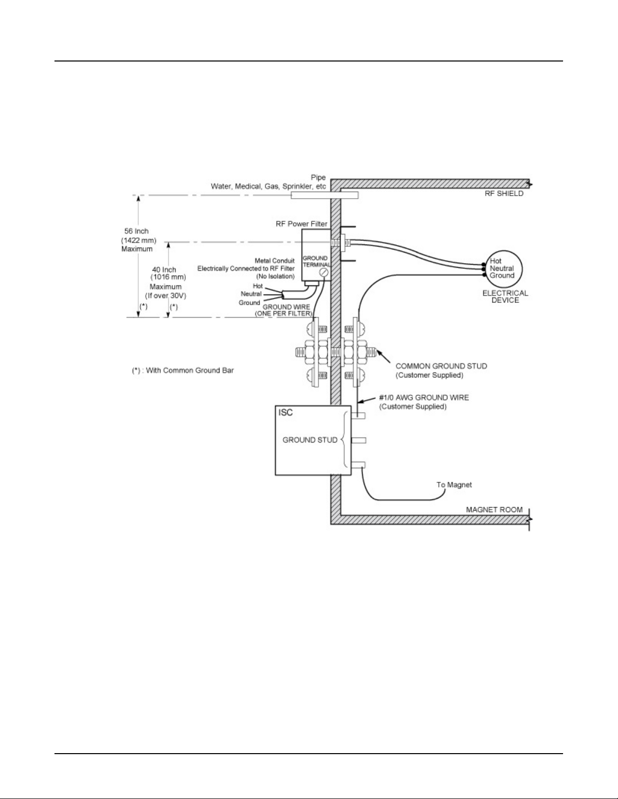
SIGNA Voyager Pre-Installation
Direction 5680008–1EN, Revision 2
6. All metallic pipes (including water, medical gas, sprinklers, etc.) entering the RF Shield,
excluding the Cryogenic Vent and floor drains, must be located within 56 inches (1422 mm)
of the RF Common Ground Stud
The illustration below shows a typical ground layout
7.
Illustration 3-22: Typical Magnet Room Grounding
96 9 Magnet Room Electrical and Grounding Requirements

Chapter 4 Equipment Room
1 Equipment Room Overview
1.1 Equipment Room Layout
The illustration below shows an Equipment room layout example. Shaded areas indicate
service/installation area.
Illustration 4-1: Equipment Room Layout Example
SIGNA Voyager Pre-Installation
Direction 5680008–1EN, Revision 2
NOTE:
Chapter 4 Equipment Room 97
1. All dimensions are in inches; bracketed dimensions are in millimeters.
2. MDP is not shown in this layout. Please also consider the MDP service area
described in Main Disconnect Panel (MDP) Option if applied.
If GE MDP is installed, 30A Breaker is also required which is not shown in layout
3.
illustration. Refer to MR Suite Electrical Requirements for 30A Breaker details.
4. Regarding “a” in illustration above, 11.8inch (300mm) side space is for excess
cable storage. Left side space 5.9(150) and right side space 11.8 (300) can be
swapped.

1.2 Components in Equipment Room
1. Integrated System Cabinet (ISC)
Integrated Cooling Cabinet (ICC)
2.
Magnet Monitor (MON)
3.
4. Main Disconnect Panel (MDP)
Optional: Magnetic Resonance Elastography (MRE)
5.
SIGNA Voyager Pre-Installation
Direction 5680008–1EN, Revision 2
98 1 Equipment Room Overview

2 Equipment room hardware components
2.1 Integrated System Cabinet (ISC)
Weight: 2557 lbs (1160kg)
Magnetic Field Limit: 50 gauss (5mT) (Penetration Panel side)
Illustration 4-2: Integrated System Cabinet (ISC)
SIGNA Voyager Pre-Installation
Direction 5680008–1EN, Revision 2
NOTE: Dimensions are in inches. Bracketed dimensions are in millimeters.
Chapter 4 Equipment Room 99

SIGNA Voyager Pre-Installation
Direction 5680008–1EN, Revision 2
Illustration 4-3: ISC Anchor Location (For Seismic Area): Front View of ISC Base Cover
100 2 Equipment room hardware components
 Loading...