

GE Sievers 900 Series Operation And Maintenance Manual

Sievers 900 On-Line
Total Organic Carbon Analyzer
Operation and
Maintenance Manual
Firmware Version 1.31 or later
6060 Spine Road
Boulder, CO 80301 USA
phone 800.255.6964 • 303.444.2009
fax 303.444.9543 DLM 90488-01 Rev. A
www.geinstruments.com Printed in USA ©2009

Identification Records
Default Administrator User ID: ADMIN
Default Administrator Password: GEAI
Analyzer serial number: _______________________
(This appears on label on the left side of the Analyzer.)
Date of receipt and installation of Analyzer: _______________________
(This is the warranty start date.)
GE Analytical Instruments ©2009 2 of 236 DLM 90488-01 Rev. A

Table of Contents
Identification Records . . . . . . . . . . . . . . . . . . . . . . . . . . . . . . . . . . . . . . . . . . . . . . . . . . . . . . . . . . . . . 2
List of Tables . . . . . . . . . . . . . . . . . . . . . . . . . . . . . . . . . . . . . . . . . . . . . . . . . . . . . . . . . . . . . . . . . . . . . 9
List of Figures . . . . . . . . . . . . . . . . . . . . . . . . . . . . . . . . . . . . . . . . . . . . . . . . . . . . . . . . . . . . . . . . . . . . 11
Revision History . . . . . . . . . . . . . . . . . . . . . . . . . . . . . . . . . . . . . . . . . . . . . . . . . . . . . . . . . . . . . . . . . . 13
Trademarks and Patents . . . . . . . . . . . . . . . . . . . . . . . . . . . . . . . . . . . . . . . . . . . . . . . . . . . . . . . . . . 14
Confidentiality . . . . . . . . . . . . . . . . . . . . . . . . . . . . . . . . . . . . . . . . . . . . . . . . . . . . . . . . . . . . . . . . . . . 15
Declaration of Conformity . . . . . . . . . . . . . . . . . . . . . . . . . . . . . . . . . . . . . . . . . . . . . . . . . . . . . . . . . 15
Standard Limited Warranty . . . . . . . . . . . . . . . . . . . . . . . . . . . . . . . . . . . . . . . . . . . . . . . . . . . . . . . 15
Limitation of Remedies and Liability . . . . . . . . . . . . . . . . . . . . . . . . . . . . . . . . . . . . . . . . . . . . . . 17
Limitación de remedios y responsabilidad . . . . . . . . . . . . . . . . . . . . . . . . . . . . . . . . . . . . . . . . 17
Limites de correction et de fiabilité . . . . . . . . . . . . . . . . . . . . . . . . . . . . . . . . . . . . . . . . . . . . . . . 18
Beschränkte Ansprüche und Haftung . . . . . . . . . . . . . . . . . . . . . . . . . . . . . . . . . . . . . . . . . . . . 18
Limitazione di rimedi e responsabilità . . . . . . . . . . . . . . . . . . . . . . . . . . . . . . . . . . . . . . . . . . . . 19
赔偿与责任限制
. . . . . . . . . . . . . . . . . . . . . . . . . . . . . . . . . . . . . . . . . . . . . . . . . . . . . . . 20
Warnings . . . . . . . . . . . . . . . . . . . . . . . . . . . . . . . . . . . . . . . . . . . . . . . . . . . . . . . . . . . . . . . . . . . . . . . . 21
Chapter 1: Introduction . . . . . . . . . . . . . . . . . . . . . . . . . . . . . . . . . . . . . . . . . . . . . . . . . . . . . . . . . . . 49
Chapter 2: System Description . . . . . . . . . . . . . . . . . . . . . . . . . . . . . . . . . . . . . . . . . . . . . . . . . . . . . 51
System Specifications* . . . . . . . . . . . . . . . . . . . . . . . . . . . . . . . . . . . . . . . . . . . . . . . . . . . . . . . . . . . . . . . . . . 51
System Overview . . . . . . . . . . . . . . . . . . . . . . . . . . . . . . . . . . . . . . . . . . . . . . . . . . . . . . . . . . . . . . . . . . . . . . . . 53
Sample Flow Path . . . . . . . . . . . . . . . . . . . . . . . . . . . . . . . . . . . . . . . . . . . . . . . . . . . . . . . . . . . . . . . . . . . . . . . 55
Additional System Components . . . . . . . . . . . . . . . . . . . . . . . . . . . . . . . . . . . . . . . . . . . . . . . . . . . . . . . . . . 57
Microprocessor Controller and Electronics . . . . . . . . . . . . . . . . . . . . . . . . . . . . . . . . . . . . . . . . . . . . 57
Data Outputs . . . . . . . . . . . . . . . . . . . . . . . . . . . . . . . . . . . . . . . . . . . . . . . . . . . . . . . . . . . . . . . . . . . 57
Major Accessories and Configurations . . . . . . . . . . . . . . . . . . . . . . . . . . . . . . . . . . . . . . . . . . . . . . . . . . . . 58
Inorganic Carbon Remover (ICR) Unit . . . . . . . . . . . . . . . . . . . . . . . . . . . . . . . . . . . . . . . . . . . . . . . . . 58
GE Analytical Instruments ©2009 3 of 236 DLM 90488-01 Rev. A

Chapter 3: Installation . . . . . . . . . . . . . . . . . . . . . . . . . . . . . . . . . . . . . . . . . . . . . . . . . . . . . . . . . . . . 59
Overview . . . . . . . . . . . . . . . . . . . . . . . . . . . . . . . . . . . . . . . . . . . . . . . . . . . . . . . . . . . . . . . . . . . . . . . . . . . . . . . . 59
Step 1: Unpack and Inspect the Analyzer . . . . . . . . . . . . . . . . . . . . . . . . . . . . . . . . . . . . . . . . . . . . . . . . . 60
Additional Installation Equipment. . . . . . . . . . . . . . . . . . . . . . . . . . . . . . . . . . . . . . . . . . . . . . . . . . . . . 61
Step 2: Complete the Identification Records . . . . . . . . . . . . . . . . . . . . . . . . . . . . . . . . . . . . . . . . . . . . . . . 61
Step 3: Select a Location for the Analyzer . . . . . . . . . . . . . . . . . . . . . . . . . . . . . . . . . . . . . . . . . . . . . . . . . 62
Step 4: Install the Reagent Cartridges . . . . . . . . . . . . . . . . . . . . . . . . . . . . . . . . . . . . . . . . . . . . . . . . . . . . 65
Remove Internal Packing Materials . . . . . . . . . . . . . . . . . . . . . . . . . . . . . . . . . . . . . . . . . . . . . . 67
Step 5: Fill the DI Water Reservoir . . . . . . . . . . . . . . . . . . . . . . . . . . . . . . . . . . . . . . . . . . . . . . . . . . . . . . . . 67
Step 6: Install Accessories and Cables . . . . . . . . . . . . . . . . . . . . . . . . . . . . . . . . . . . . . . . . . . . . . . . . . . . . 68
. . . . . . . . . . . . . . . . . . . . . . . . . . . . . . . . . . . . . . . . . . . . . . . . . . . . . . . . . . . . . . . . . . . . . . . . . . . . . . . . . . . . . 68
Installing the Analog Outputs and Alarms . . . . . . . . . . . . . . . . . . . . . . . . . . . . . . . . . . . . . . . . . . . . . 68
Wiring the 4-20 mA Connection . . . . . . . . . . . . . . . . . . . . . . . . . . . . . . . . . . . . . . . . . . . . . . . . . . 70
Wiring the Remote Start (Binary Input) Connection . . . . . . . . . . . . . . . . . . . . . . . . . . . . . . . . 71
Using the Binary Output . . . . . . . . . . . . . . . . . . . . . . . . . . . . . . . . . . . . . . . . . . . . . . . . . . . . . . . . . 73
Installing the Printer . . . . . . . . . . . . . . . . . . . . . . . . . . . . . . . . . . . . . . . . . . . . . . . . . . . . . . . . . . . . . . . . . 73
Installing the USB Connection . . . . . . . . . . . . . . . . . . . . . . . . . . . . . . . . . . . . . . . . . . . . . . . . . . . . . . . . 73
Installing the Serial Connection. . . . . . . . . . . . . . . . . . . . . . . . . . . . . . . . . . . . . . . . . . . . . . . . . . . . . . . 74
Connecting to a Power Supply. . . . . . . . . . . . . . . . . . . . . . . . . . . . . . . . . . . . . . . . . . . . . . . . . . . . . . . . 75
Step 7: Connect the Sample Inlet System . . . . . . . . . . . . . . . . . . . . . . . . . . . . . . . . . . . . . . . . . . . . . . . . . 76
Installing the Integrated On-Line Sample System . . . . . . . . . . . . . . . . . . . . . . . . . . . . . . . . . . . . . . 76
Installing the Grab Sample Inlet System. . . . . . . . . . . . . . . . . . . . . . . . . . . . . . . . . . . . . . . . . . . . . . . 77
Step 8: Configure Basic Analyzer Settings . . . . . . . . . . . . . . . . . . . . . . . . . . . . . . . . . . . . . . . . . . . . . . . . . 78
Powering the Analyzer On. . . . . . . . . . . . . . . . . . . . . . . . . . . . . . . . . . . . . . . . . . . . . . . . . . . . . . . . . . . . 79
Enabling DataGuard or Password Protection (Optional) . . . . . . . . . . . . . . . . . . . . . . . . . . . . . . . . 79
Enabling Password Protection . . . . . . . . . . . . . . . . . . . . . . . . . . . . . . . . . . . . . . . . . . . . . . . . . . . 80
Enabling DataGuard . . . . . . . . . . . . . . . . . . . . . . . . . . . . . . . . . . . . . . . . . . . . . . . . . . . . . . . . . . . . 80
Establishing a New Administrator Account for DataGuard . . . . . . . . . . . . . . . . . . . . . . . . . 81
Setting the Clock and Time Zone. . . . . . . . . . . . . . . . . . . . . . . . . . . . . . . . . . . . . . . . . . . . . . . . . . . . . . 82
Naming the Analyzer Location (Optional). . . . . . . . . . . . . . . . . . . . . . . . . . . . . . . . . . . . . . . . . . . . . . 82
Setting Reagent Expiration Dates. . . . . . . . . . . . . . . . . . . . . . . . . . . . . . . . . . . . . . . . . . . . . . . . . . . . . 83
Setting the Analyzer Mode and Reagent Flow Rates . . . . . . . . . . . . . . . . . . . . . . . . . . . . . . . . . . . 84
Setting Up the Data History . . . . . . . . . . . . . . . . . . . . . . . . . . . . . . . . . . . . . . . . . . . . . . . . . . . . . . . . . . 84
Setting Up the Printer (Optional) . . . . . . . . . . . . . . . . . . . . . . . . . . . . . . . . . . . . . . . . . . . . . . . . . . . . . . 84
Exporting and Printing Constants. . . . . . . . . . . . . . . . . . . . . . . . . . . . . . . . . . . . . . . . . . . . . . . . . . . . . 85
Set Up Data I/O . . . . . . . . . . . . . . . . . . . . . . . . . . . . . . . . . . . . . . . . . . . . . . . . . . . . . . . . . . . . . . . . . . . . . . 85
Step 9: Flushing and Rinsing the Analyzer . . . . . . . . . . . . . . . . . . . . . . . . . . . . . . . . . . . . . . . . . . . . . . . . . 86
GE Analytical Instruments ©2009 4 of 236 DLM 90488-01 Rev. A

Chapter 4: Basic Analyzer Operation . . . . . . . . . . . . . . . . . . . . . . . . . . . . . . . . . . . . . . . . . . . . . . . 89
Overview . . . . . . . . . . . . . . . . . . . . . . . . . . . . . . . . . . . . . . . . . . . . . . . . . . . . . . . . . . . . . . . . . . . . . . . . . . . . . . . . 89
The Main Screen. . . . . . . . . . . . . . . . . . . . . . . . . . . . . . . . . . . . . . . . . . . . . . . . . . . . . . . . . . . . . . . . . . . . . 90
Taking TOC Measurements . . . . . . . . . . . . . . . . . . . . . . . . . . . . . . . . . . . . . . . . . . . . . . . . . . . . . . . . . . . 91
The Menu Screen . . . . . . . . . . . . . . . . . . . . . . . . . . . . . . . . . . . . . . . . . . . . . . . . . . . . . . . . . . . . . . . . . . . . 91
Setup . . . . . . . . . . . . . . . . . . . . . . . . . . . . . . . . . . . . . . . . . . . . . . . . . . . . . . . . . . . . . . . . . . . . . . . . . . . . . . . . . . . 92
Setting the Analyzer Mode . . . . . . . . . . . . . . . . . . . . . . . . . . . . . . . . . . . . . . . . . . . . . . . . . . . . . . . . . . . 93
Grab Mode Measurement Settings. . . . . . . . . . . . . . . . . . . . . . . . . . . . . . . . . . . . . . . . . . . . . . . . . . . . 93
Setting Reagent Flow Rates . . . . . . . . . . . . . . . . . . . . . . . . . . . . . . . . . . . . . . . . . . . . . . . . . . . . . . . . . . 94
Using the Autoreagent Function . . . . . . . . . . . . . . . . . . . . . . . . . . . . . . . . . . . . . . . . . . . . . . . . . 97
Scheduling Autoreagent Adjustments in On-Line Mode . . . . . . . . . . . . . . . . . . . . . . . . . . . 98
Setting Manual Flow Rates . . . . . . . . . . . . . . . . . . . . . . . . . . . . . . . . . . . . . . . . . . . . . . . . . . . . . . 98
Understanding Analysis Times. . . . . . . . . . . . . . . . . . . . . . . . . . . . . . . . . . . . . . . . . . . . . . . . . . . . . . . . 99
Managing Data History . . . . . . . . . . . . . . . . . . . . . . . . . . . . . . . . . . . . . . . . . . . . . . . . . . . . . . . . . . . . . . . . .100
Setting up Data History . . . . . . . . . . . . . . . . . . . . . . . . . . . . . . . . . . . . . . . . . . . . . . . . . . . . . . . . . . . . 100
Archiving Data History . . . . . . . . . . . . . . . . . . . . . . . . . . . . . . . . . . . . . . . . . . . . . . . . . . . . . . . . . . . . . 101
Viewing Data History. . . . . . . . . . . . . . . . . . . . . . . . . . . . . . . . . . . . . . . . . . . . . . . . . . . . . . . . . . . . . . . 101
Graphing Data History . . . . . . . . . . . . . . . . . . . . . . . . . . . . . . . . . . . . . . . . . . . . . . . . . . . . . . . . . . . . . 102
Printing Data History. . . . . . . . . . . . . . . . . . . . . . . . . . . . . . . . . . . . . . . . . . . . . . . . . . . . . . . . . . . . . . . 104
Exporting Data History . . . . . . . . . . . . . . . . . . . . . . . . . . . . . . . . . . . . . . . . . . . . . . . . . . . . . . . . . . . . . 104
Setting Up Analyzer Input and Output . . . . . . . . . . . . . . . . . . . . . . . . . . . . . . . . . . . . . . . . . . . . . . . . . . .105
Setting Up Analog Output . . . . . . . . . . . . . . . . . . . . . . . . . . . . . . . . . . . . . . . . . . . . . . . . . . . . . . . . . . 105
Calibrating Analog Output Values . . . . . . . . . . . . . . . . . . . . . . . . . . . . . . . . . . . . . . . . . . . . . . .106
Setting Up Serial Output. . . . . . . . . . . . . . . . . . . . . . . . . . . . . . . . . . . . . . . . . . . . . . . . . . . . . . . . . . . . 107
Interpreting Serial Output . . . . . . . . . . . . . . . . . . . . . . . . . . . . . . . . . . . . . . . . . . . . . . . . . . . . . .108
Issuing Serial Commands to the Analyzer . . . . . . . . . . . . . . . . . . . . . . . . . . . . . . . . . . . . . . . . . . . 109
Configuring Printer Settings . . . . . . . . . . . . . . . . . . . . . . . . . . . . . . . . . . . . . . . . . . . . . . . . . . . . . . . . 109
Activating Binary Input. . . . . . . . . . . . . . . . . . . . . . . . . . . . . . . . . . . . . . . . . . . . . . . . . . . . . . . . . . . . . 110
Setting Alarm Values. . . . . . . . . . . . . . . . . . . . . . . . . . . . . . . . . . . . . . . . . . . . . . . . . . . . . . . . . . . . . . . 110
Managing Maintenance Information . . . . . . . . . . . . . . . . . . . . . . . . . . . . . . . . . . . . . . . . . . . . . . . . . . . .111
Displaying Consumables Status . . . . . . . . . . . . . . . . . . . . . . . . . . . . . . . . . . . . . . . . . . . . . . . . . . . . 112
Setting the Analyzer Clock and Time Zone. . . . . . . . . . . . . . . . . . . . . . . . . . . . . . . . . . . . . . . . . . . 113
Reviewing Warnings and Errors . . . . . . . . . . . . . . . . . . . . . . . . . . . . . . . . . . . . . . . . . . . . . . . . . . . . 113
Displaying System Information . . . . . . . . . . . . . . . . . . . . . . . . . . . . . . . . . . . . . . . . . . . . . . . . . . . . . 114
Advanced Analyzer Settings . . . . . . . . . . . . . . . . . . . . . . . . . . . . . . . . . . . . . . . . . . . . . . . . . . . . . . . . . . . . 115
Printing the Current Constants Values . . . . . . . . . . . . . . . . . . . . . . . . . . . . . . . . . . . . . . . . . . . . . . 115
Changing the Display Mode . . . . . . . . . . . . . . . . . . . . . . . . . . . . . . . . . . . . . . . . . . . . . . . . . . . . . . . . 116
Naming the Analyzer Location. . . . . . . . . . . . . . . . . . . . . . . . . . . . . . . . . . . . . . . . . . . . . . . . . . . . . . 116
GE Analytical Instruments ©2009 5 of 236 DLM 90488-01 Rev. A

Adjusting Display Contrast Settings . . . . . . . . . . . . . . . . . . . . . . . . . . . . . . . . . . . . . . . . . . . . . . . . . 116
Saving System Settings . . . . . . . . . . . . . . . . . . . . . . . . . . . . . . . . . . . . . . . . . . . . . . . . . . . . . . . . . . . . 117
Programming the TOC Autozero . . . . . . . . . . . . . . . . . . . . . . . . . . . . . . . . . . . . . . . . . . . . . . . . . . . . 117
Selecting the Program Language . . . . . . . . . . . . . . . . . . . . . . . . . . . . . . . . . . . . . . . . . . . . . . . . . . . 118
Configuring the Flow Sensor . . . . . . . . . . . . . . . . . . . . . . . . . . . . . . . . . . . . . . . . . . . . . . . . . . . . . . . . . . . . 118
Basic Hardware Operation Issues . . . . . . . . . . . . . . . . . . . . . . . . . . . . . . . . . . . . . . . . . . . . . . . . . . . . . . . 119
Opening the Analyzer Case. . . . . . . . . . . . . . . . . . . . . . . . . . . . . . . . . . . . . . . . . . . . . . . . . . . . . . . . . 119
The Touch Screen. . . . . . . . . . . . . . . . . . . . . . . . . . . . . . . . . . . . . . . . . . . . . . . . . . . . . . . . . . . . . . . . . . 119
The IOS System . . . . . . . . . . . . . . . . . . . . . . . . . . . . . . . . . . . . . . . . . . . . . . . . . . . . . . . . . . . . . . . . . . . . 120
Chapter 5: Password Protection and DataGuard . . . . . . . . . . . . . . . . . . . . . . . . . . . . . . . . . . . .123
Overview . . . . . . . . . . . . . . . . . . . . . . . . . . . . . . . . . . . . . . . . . . . . . . . . . . . . . . . . . . . . . . . . . . . . . . . . . . . . . . .123
Using Password Protection . . . . . . . . . . . . . . . . . . . . . . . . . . . . . . . . . . . . . . . . . . . . . . . . . . . . . . . . . . . . .125
Enabling Password Protection . . . . . . . . . . . . . . . . . . . . . . . . . . . . . . . . . . . . . . . . . . . . . . . . . . . . . . 125
Changing the Password. . . . . . . . . . . . . . . . . . . . . . . . . . . . . . . . . . . . . . . . . . . . . . . . . . . . . . . . . . . . 125
Configuring Password Settings . . . . . . . . . . . . . . . . . . . . . . . . . . . . . . . . . . . . . . . . . . . . . . . . . . . . . 126
Disabling Password Protection . . . . . . . . . . . . . . . . . . . . . . . . . . . . . . . . . . . . . . . . . . . . . . . . . . . . . 126
Using DataGuard . . . . . . . . . . . . . . . . . . . . . . . . . . . . . . . . . . . . . . . . . . . . . . . . . . . . . . . . . . . . . . . . . . . . . . .126
Enabling DataGuard . . . . . . . . . . . . . . . . . . . . . . . . . . . . . . . . . . . . . . . . . . . . . . . . . . . . . . . . . . . . . . . 127
Adding User IDs . . . . . . . . . . . . . . . . . . . . . . . . . . . . . . . . . . . . . . . . . . . . . . . . . . . . . . . . . . . . . . . . . . . 128
Editing User Information . . . . . . . . . . . . . . . . . . . . . . . . . . . . . . . . . . . . . . . . . . . . . . . . . . . . . . . . . . . 128
Configuring Login Settings . . . . . . . . . . . . . . . . . . . . . . . . . . . . . . . . . . . . . . . . . . . . . . . . . . . . . . . . . 129
Changing User Passwords . . . . . . . . . . . . . . . . . . . . . . . . . . . . . . . . . . . . . . . . . . . . . . . . . . . . . . . . . 130
Dealing with Forgotten Passwords. . . . . . . . . . . . . . . . . . . . . . . . . . . . . . . . . . . . . . . . . . . . . . . . . . 130
Reactivating Inactivated User Accounts. . . . . . . . . . . . . . . . . . . . . . . . . . . . . . . . . . . . . . . . . . . . . 131
Archiving User Accounts . . . . . . . . . . . . . . . . . . . . . . . . . . . . . . . . . . . . . . . . . . . . . . . . . . . . . . . . . . . 131
Viewing, Exporting, and Printing Audit Trails. . . . . . . . . . . . . . . . . . . . . . . . . . . . . . . . . . . . . . . . . 132
Chapter 6: Calibration, Verification, and System Suitability . . . . . . . . . . . . . . . . . . . . . . . . . .135
Overview . . . . . . . . . . . . . . . . . . . . . . . . . . . . . . . . . . . . . . . . . . . . . . . . . . . . . . . . . . . . . . . . . . . . . . . . . . . . . . .135
Required Calibration Supplies . . . . . . . . . . . . . . . . . . . . . . . . . . . . . . . . . . . . . . . . . . . . . . . . . . . . . . . . . . .136
Preparing for Calibration . . . . . . . . . . . . . . . . . . . . . . . . . . . . . . . . . . . . . . . . . . . . . . . . . . . . . . . . . . . . . . . . 139
Export Current Constants . . . . . . . . . . . . . . . . . . . . . . . . . . . . . . . . . . . . . . . . . . . . . . . . . . . . . . . . . . 139
Perform Annual Maintenance Tasks . . . . . . . . . . . . . . . . . . . . . . . . . . . . . . . . . . . . . . . . . . . . . . . . 140
Perform a TOC Autozero . . . . . . . . . . . . . . . . . . . . . . . . . . . . . . . . . . . . . . . . . . . . . . . . . . . . . . . . . . . 140
Perform a Sample Flow Rate Calibration . . . . . . . . . . . . . . . . . . . . . . . . . . . . . . . . . . . . . . . . . . . . 141
Handling Standards. . . . . . . . . . . . . . . . . . . . . . . . . . . . . . . . . . . . . . . . . . . . . . . . . . . . . . . . . . . . . . . . 143
Performing a Single-Point Calibration . . . . . . . . . . . . . . . . . . . . . . . . . . . . . . . . . . . . . . . . . . . . . . . . . . .143
GE Analytical Instruments ©2009 6 of 236 DLM 90488-01 Rev. A

Performing a Multi-Point Calibration . . . . . . . . . . . . . . . . . . . . . . . . . . . . . . . . . . . . . . . . . . . . . . . . . . . . .146
Performing a Calibration Verification . . . . . . . . . . . . . . . . . . . . . . . . . . . . . . . . . . . . . . . . . . . . . . . . . . . .149
System Suitability Verification . . . . . . . . . . . . . . . . . . . . . . . . . . . . . . . . . . . . . . . . . . . . . . . . . . . . . . . . . . .151
Performing an Autoreagent Calibration . . . . . . . . . . . . . . . . . . . . . . . . . . . . . . . . . . . . . . . . . . . . . . . . . .153
Performing an Autoreagent Verification . . . . . . . . . . . . . . . . . . . . . . . . . . . . . . . . . . . . . . . . . . . . . . . . .155
Reviewing Calibration and Verification History . . . . . . . . . . . . . . . . . . . . . . . . . . . . . . . . . . . . . . . . . . . 157
Chapter 7: Maintenance . . . . . . . . . . . . . . . . . . . . . . . . . . . . . . . . . . . . . . . . . . . . . . . . . . . . . . . . . 171
Replacing Consumables and Maintenance Items . . . . . . . . . . . . . . . . . . . . . . . . . . . . . . . . . . . . . . . . 171
Checking and Refilling the DI Water Reservoir . . . . . . . . . . . . . . . . . . . . . . . . . . . . . . . . . . . . . . . . . . . .173
Replacing the Chemical Reagents . . . . . . . . . . . . . . . . . . . . . . . . . . . . . . . . . . . . . . . . . . . . . . . . . . 175
Replacing the UV Lamp . . . . . . . . . . . . . . . . . . . . . . . . . . . . . . . . . . . . . . . . . . . . . . . . . . . . . . . . . . . . 176
Replacing the Sample Pump Tubing . . . . . . . . . . . . . . . . . . . . . . . . . . . . . . . . . . . . . . . . . . . . . . . . 179
Replacing the Ion Exchange Resin (Resin Bed) . . . . . . . . . . . . . . . . . . . . . . . . . . . . . . . . . . . . . . . 182
Resin Bed Replacement with a Silver-Colored Bracket . . . . . . . . . . . . . . . . . . . . . . . . . . .182
Resin Bed Replacement with a Brass-Colored Bracket . . . . . . . . . . . . . . . . . . . . . . . . . . .185
Replacing the In-Line Filter Element. . . . . . . . . . . . . . . . . . . . . . . . . . . . . . . . . . . . . . . . . . . . . . . . . 188
Setting the Installation or Expiration Date for New Consumables. . . . . . . . . . . . . . . . . . . . . 190
Flushing the Reagent Syringes . . . . . . . . . . . . . . . . . . . . . . . . . . . . . . . . . . . . . . . . . . . . . . . . . . . . . . . . . . 191
Cleaning the Analyzer . . . . . . . . . . . . . . . . . . . . . . . . . . . . . . . . . . . . . . . . . . . . . . . . . . . . . . . . . . . . . . . . . . 192
Chapter 8: Troubleshooting . . . . . . . . . . . . . . . . . . . . . . . . . . . . . . . . . . . . . . . . . . . . . . . . . . . . . .195
Overview . . . . . . . . . . . . . . . . . . . . . . . . . . . . . . . . . . . . . . . . . . . . . . . . . . . . . . . . . . . . . . . . . . . . . . . . . . . . . . .195
Step 1: Review Warnings and Errors . . . . . . . . . . . . . . . . . . . . . . . . . . . . . . . . . . . . . . . . . . . . . . . . . . . . .195
Warnings and Error Messages . . . . . . . . . . . . . . . . . . . . . . . . . . . . . . . . . . . . . . . . . . . . . . . . . . . . . 196
Step 2: Visual Inspection . . . . . . . . . . . . . . . . . . . . . . . . . . . . . . . . . . . . . . . . . . . . . . . . . . . . . . . . . . . . . . . . 201
External Inspection . . . . . . . . . . . . . . . . . . . . . . . . . . . . . . . . . . . . . . . . . . . . . . . . . . . . . . . . . . . . . . . . 202
Internal Inspection. . . . . . . . . . . . . . . . . . . . . . . . . . . . . . . . . . . . . . . . . . . . . . . . . . . . . . . . . . . . . . . . . 202
Step 3: Review Solutions for Basic Problems . . . . . . . . . . . . . . . . . . . . . . . . . . . . . . . . . . . . . . . . . . . . .203
The Analyzer Will Not Power On . . . . . . . . . . . . . . . . . . . . . . . . . . . . . . . . . . . . . . . . . . . . . . . . . . . . 203
Problems with the DI Water Pump . . . . . . . . . . . . . . . . . . . . . . . . . . . . . . . . . . . . . . . . . . . . . . . . . . 203
Checking the Sample Pump . . . . . . . . . . . . . . . . . . . . . . . . . . . . . . . . . . . . . . . . . . . . . . . . . . . .204
Checking the Inlet Tubing . . . . . . . . . . . . . . . . . . . . . . . . . . . . . . . . . . . . . . . . . . . . . . . . . . . . . . .205
Backflushing the Analyzer. . . . . . . . . . . . . . . . . . . . . . . . . . . . . . . . . . . . . . . . . . . . . . . . . . . . . . . . . . 205
Gas Bubbles Are Present in Reagent Lines or Syringes . . . . . . . . . . . . . . . . . . . . . . . . . . . . . . . . . . . .210
pH of Sample Stream is Too High . . . . . . . . . . . . . . . . . . . . . . . . . . . . . . . . . . . . . . . . . . . . . . . . . . . . . . . .210
Erratic Readings Due to High IC . . . . . . . . . . . . . . . . . . . . . . . . . . . . . . . . . . . . . . . . . . . . . . . . . . . . . . . . .211
Negative Measurements . . . . . . . . . . . . . . . . . . . . . . . . . . . . . . . . . . . . . . . . . . . . . . . . . . . . . . . . . . . . . . . .211
GE Analytical Instruments ©2009 7 of 236 DLM 90488-01 Rev. A

Conductivity Autozero . . . . . . . . . . . . . . . . . . . . . . . . . . . . . . . . . . . . . . . . . . . . . . . . . . . . . . . . . . . . . 211
Problems Changing the Program Language . . . . . . . . . . . . . . . . . . . . . . . . . . . . . . . . . . . . . . . . . . . . .212
Disabling the UV Lamp . . . . . . . . . . . . . . . . . . . . . . . . . . . . . . . . . . . . . . . . . . . . . . . . . . . . . . . . . . . . . . . . .212
Step 4: Contact Technical Support . . . . . . . . . . . . . . . . . . . . . . . . . . . . . . . . . . . . . . . . . . . . . . . . . . . . . . .213
Step 5: Return the Analyzer to GE Analytical Instruments . . . . . . . . . . . . . . . . . . . . . . . . . . . . . . . . . 213
Chapter 9: Turbo Operation . . . . . . . . . . . . . . . . . . . . . . . . . . . . . . . . . . . . . . . . . . . . . . . . . . . . . . 219
Introduction . . . . . . . . . . . . . . . . . . . . . . . . . . . . . . . . . . . . . . . . . . . . . . . . . . . . . . . . . . . . . . . . . . . . . . . . . . . .219
Turbo Mode Specifications . . . . . . . . . . . . . . . . . . . . . . . . . . . . . . . . . . . . . . . . . . . . . . . . . . . . . . . . . . . . . .220
Enabling Turbo Mode . . . . . . . . . . . . . . . . . . . . . . . . . . . . . . . . . . . . . . . . . . . . . . . . . . . . . . . . . . . . . . . . . . .220
Turning Turbo Mode On and Off . . . . . . . . . . . . . . . . . . . . . . . . . . . . . . . . . . . . . . . . . . . . . . . . . . . . . . . . .220
Reagent Flow Rates . . . . . . . . . . . . . . . . . . . . . . . . . . . . . . . . . . . . . . . . . . . . . . . . . . . . . . . . . . . . . . . . . . . .221
Performing a Turbo Calibration . . . . . . . . . . . . . . . . . . . . . . . . . . . . . . . . . . . . . . . . . . . . . . . . . . . . . . . . .221
Performing a Turbo Calibration Verification . . . . . . . . . . . . . . . . . . . . . . . . . . . . . . . . . . . . . . . . . . . . . . 222
Turbo Mode Maintenance Considerations . . . . . . . . . . . . . . . . . . . . . . . . . . . . . . . . . . . . . . . . . . . . . . . 224
Appendix: Transferring Data to a PC . . . . . . . . . . . . . . . . . . . . . . . . . . . . . . . . . . . . . . . . . . . . . .225
Importing Data into a Spreadsheet Program . . . . . . . . . . . . . . . . . . . . . . . . . . . . . . . . . . . . . . . . . . . . .225
Using HyperTerminal . . . . . . . . . . . . . . . . . . . . . . . . . . . . . . . . . . . . . . . . . . . . . . . . . . . . . . . . . . . . . . . . . . . 228
Determining Your Communications Port Number. . . . . . . . . . . . . . . . . . . . . . . . . . . . . . . . . . . . 230
Index . . . . . . . . . . . . . . . . . . . . . . . . . . . . . . . . . . . . . . . . . . . . . . . . . . . . . . . . . . . . . . . . . . . . . . . . . . .231
GE Analytical Instruments ©2009 8 of 236 DLM 90488-01 Rev. A

List of Tables
Table 1 Alarm Inputs/Outputs (TB2) . . . . . . . . . . . . . . . . . . . . . . . . . . . . . . . . . . . . . . . . . . . . . . . . . . . . . . . .69
Table 2 Sample Sequencer Inputs/Outputs (TB1) . . . . . . . . . . . . . . . . . . . . . . . . . . . . . . . . . . . . . . . . . . .69
Table 3 Serial and 4-20 mA Inputs/Outputs (TB3) . . . . . . . . . . . . . . . . . . . . . . . . . . . . . . . . . . . . . . . . . . .70
Table 4 Acid Flow Rate for Preliminary Measurement with Autoreagent Function . . . . . . . . . . . .94
Table 5 Recommended Oxidizer Flow Rates . . . . . . . . . . . . . . . . . . . . . . . . . . . . . . . . . . . . . . . . . . . . . . .98
Table 6 Recommended Acid Flow Rates . . . . . . . . . . . . . . . . . . . . . . . . . . . . . . . . . . . . . . . . . . . . . . . . . . .99
Table 7 Sample Analysis Times . . . . . . . . . . . . . . . . . . . . . . . . . . . . . . . . . . . . . . . . . . . . . . . . . . . . . . . . . . . .99
Table 8 Data Fields Output to the Serial (RS-232) Port . . . . . . . . . . . . . . . . . . . . . . . . . . . . . . . . . . . . 108
Table 9 Audit Trail Output Format . . . . . . . . . . . . . . . . . . . . . . . . . . . . . . . . . . . . . . . . . . . . . . . . . . . . . . . 133
Table 10 Record of User IDs . . . . . . . . . . . . . . . . . . . . . . . . . . . . . . . . . . . . . . . . . . . . . . . . . . . . . . . . . . . . . . 134
Table 11 Standards Required for Multi-Point Calibration . . . . . . . . . . . . . . . . . . . . . . . . . . . . . . . . . . . 137
Table 12 Standards Required for Single-Point Calibration . . . . . . . . . . . . . . . . . . . . . . . . . . . . . . . . . . 138
Table 13 Standards Required for Calibration Verification . . . . . . . . . . . . . . . . . . . . . . . . . . . . . . . . . . 138
Table 14 Standards Required for System Suitability Verification . . . . . . . . . . . . . . . . . . . . . . . . . . . . 138
Table 15 Standards Required for Autoreagent Calibration . . . . . . . . . . . . . . . . . . . . . . . . . . . . . . . . . 139
Table 16 Standards Required for Autoreagent Verification . . . . . . . . . . . . . . . . . . . . . . . . . . . . . . . . . 139
Table 17 Replacement Schedule for Sievers 900 Series Analyzer Consumables . . . . . . . . . . . . . 173
Table 18 Sievers 900 On-Line TOC Analyzer 1-Year Maintenance Worksheet . . . . . . . . . . . . . . . . 193
Table 19 Replacement Schedule for Consumables in Turbo Analyzers . . . . . . . . . . . . . . . . . . . . . . 224
GE Analytical Instruments ©2009 9 of 236 DLM 90488-01 Rev. A

GE Analytical Instruments ©2009 10 of 236 DLM 90488-01 Rev. A

List of Figures
Figure 1 Analyzer Schematic . . . . . . . . . . . . . . . . . . . . . . . . . . . . . . . . . . . . . . . . . . . . . . . . . . . . . . . . . . . . .54
Figure 2 Clearances Required for Installation of the Analyzer . . . . . . . . . . . . . . . . . . . . . . . . . . . . . .63
Figure 3 Left Side Dimensions of the Analyzer . . . . . . . . . . . . . . . . . . . . . . . . . . . . . . . . . . . . . . . . . . . . .64
Figure 4 Right Side Dimensions of the Analyzer . . . . . . . . . . . . . . . . . . . . . . . . . . . . . . . . . . . . . . . . . . .65
Figure 5 Filling the DI Water Reservoir . . . . . . . . . . . . . . . . . . . . . . . . . . . . . . . . . . . . . . . . . . . . . . . . . . . .67
Figure 6 Wiring Diagram for the 4-20 mA Connection . . . . . . . . . . . . . . . . . . . . . . . . . . . . . . . . . . . . .71
Figure 7 Wiring Option for Binary Input Using Analyzer’s Internal Supply . . . . . . . . . . . . . . . . . . . .72
Figure 8 Wiring Option for Binary Input Using External Supply . . . . . . . . . . . . . . . . . . . . . . . . . . . . . .72
Figure 9 Input and Output Connectors . . . . . . . . . . . . . . . . . . . . . . . . . . . . . . . . . . . . . . . . . . . . . . . . . . . .74
Figure 10 Wiring AC Power Conduit (Arrows Indicate Connection Points) . . . . . . . . . . . . . . . . . . . . .76
Figure 11 The Sievers 900 On-Line TOC Analyzer Main Screen . . . . . . . . . . . . . . . . . . . . . . . . . . . . . . .90
Figure 12 The Setup Tab . . . . . . . . . . . . . . . . . . . . . . . . . . . . . . . . . . . . . . . . . . . . . . . . . . . . . . . . . . . . . . . . . .92
Figure 13 Selecting the Reagent Flow Method . . . . . . . . . . . . . . . . . . . . . . . . . . . . . . . . . . . . . . . . . . . . . .97
Figure 14 The Data Tab . . . . . . . . . . . . . . . . . . . . . . . . . . . . . . . . . . . . . . . . . . . . . . . . . . . . . . . . . . . . . . . . . 100
Figure 15 Specifying a Start Date on the View Data Screen. . . . . . . . . . . . . . . . . . . . . . . . . . . . . . . . 102
Figure 16 Graphing the Data History . . . . . . . . . . . . . . . . . . . . . . . . . . . . . . . . . . . . . . . . . . . . . . . . . . . . . 103
Figure 17 The I/O Tab . . . . . . . . . . . . . . . . . . . . . . . . . . . . . . . . . . . . . . . . . . . . . . . . . . . . . . . . . . . . . . . . . . . 105
Figure 18 The Maintenance Tab . . . . . . . . . . . . . . . . . . . . . . . . . . . . . . . . . . . . . . . . . . . . . . . . . . . . . . . . . 112
Figure 19 The Advanced Menu with One Program Language Loaded . . . . . . . . . . . . . . . . . . . . . . 115
Figure 20 The IOS System. . . . . . . . . . . . . . . . . . . . . . . . . . . . . . . . . . . . . . . . . . . . . . . . . . . . . . . . . . . . . . . . 120
Figure 21 Menu Map with Minimum User Level . . . . . . . . . . . . . . . . . . . . . . . . . . . . . . . . . . . . . . . . . . . 124
Figure 22 The Sample Flow Rate Calibration Summary Screen . . . . . . . . . . . . . . . . . . . . . . . . . . . . 143
Figure 23 Selecting the Concentration for a Single-Point Calibration . . . . . . . . . . . . . . . . . . . . . . . 144
Figure 24 Reviewing TC and IC Values from a Single-Point Calibration . . . . . . . . . . . . . . . . . . . . . 146
Figure 25 TC Values Summary Screen in a Multi-Point Calibration. . . . . . . . . . . . . . . . . . . . . . . . . . 149
Figure 26 IC Values Summary Screen in a Multi-Point Calibration . . . . . . . . . . . . . . . . . . . . . . . . . . 149
Figure 27 System Suitability Summary Screen . . . . . . . . . . . . . . . . . . . . . . . . . . . . . . . . . . . . . . . . . . . . 153
Figure 28 The Autoreagent Calibration Summary Screen . . . . . . . . . . . . . . . . . . . . . . . . . . . . . . . . . 155
Figure 29 The Autoreagent Verification Summary Screen . . . . . . . . . . . . . . . . . . . . . . . . . . . . . . . . . 157
GE Analytical Instruments ©2009 11 of 236 DLM 90488-01 Rev. A

Figure 30 Interior Overview of the Analyzer . . . . . . . . . . . . . . . . . . . . . . . . . . . . . . . . . . . . . . . . . . . . . . 172
Figure 31 Filling the DI Water Reservoir . . . . . . . . . . . . . . . . . . . . . . . . . . . . . . . . . . . . . . . . . . . . . . . . . . 174
Figure 32 Relative Positioning of Components in the UV Lamp Assembly. . . . . . . . . . . . . . . . . . . 178
Figure 33 UV Lamp Ferrule Orientation Detail. . . . . . . . . . . . . . . . . . . . . . . . . . . . . . . . . . . . . . . . . . . . . 178
Figure 34 Replacing the Sample Pump Tubing . . . . . . . . . . . . . . . . . . . . . . . . . . . . . . . . . . . . . . . . . . . . 181
Figure 35 Resin Bed Connections . . . . . . . . . . . . . . . . . . . . . . . . . . . . . . . . . . . . . . . . . . . . . . . . . . . . . . . . 185
Figure 36 Brass-Colored Resin Bed Bracket . . . . . . . . . . . . . . . . . . . . . . . . . . . . . . . . . . . . . . . . . . . . . . 188
Figure 37 Replacing the In-Line Filter Element . . . . . . . . . . . . . . . . . . . . . . . . . . . . . . . . . . . . . . . . . . . . 190
Figure 38 The Consumables Screen . . . . . . . . . . . . . . . . . . . . . . . . . . . . . . . . . . . . . . . . . . . . . . . . . . . . . . 191
Figure 39 The DI Water Loop. . . . . . . . . . . . . . . . . . . . . . . . . . . . . . . . . . . . . . . . . . . . . . . . . . . . . . . . . . . . . 204
Figure 40 Preparing to Back Flush the Sample Side Fluidics. . . . . . . . . . . . . . . . . . . . . . . . . . . . . . . . 206
Figure 41 Comparing the Flow Rate Through the Sample Pump Tubing . . . . . . . . . . . . . . . . . . . . 207
Figure 42 Flushing the Sample Side . . . . . . . . . . . . . . . . . . . . . . . . . . . . . . . . . . . . . . . . . . . . . . . . . . . . . . 207
Figure 43 Disconnect the Tan Tubing that Connects to the DI Water Reservoir . . . . . . . . . . . . . 208
Figure 44 Preparing to Disconnect the Tubing from the Solenoid Valves. . . . . . . . . . . . . . . . . . . . 209
Figure 45 The DI Water Reservoir and Resin Bed . . . . . . . . . . . . . . . . . . . . . . . . . . . . . . . . . . . . . . . . . 216
Figure 46 Disconnect the Green Restrictor Tubing . . . . . . . . . . . . . . . . . . . . . . . . . . . . . . . . . . . . . . . . 216
Figure 47 Draining the Measurement Module . . . . . . . . . . . . . . . . . . . . . . . . . . . . . . . . . . . . . . . . . . . . 217
Figure 48 Step 1 of the MS Excel Text Import Wizard . . . . . . . . . . . . . . . . . . . . . . . . . . . . . . . . . . . . . . 226
Figure 49 Step 2 of the MS Excel Text Import Wizard . . . . . . . . . . . . . . . . . . . . . . . . . . . . . . . . . . . . . . 227
Figure 50 Step 3 of the MS Excel Text Import Wizard . . . . . . . . . . . . . . . . . . . . . . . . . . . . . . . . . . . . . . 228
GE Analytical Instruments ©2009 12 of 236 DLM 90488-01 Rev. A

Revision History
New editions are complete revisions of the manual and incorporate the content of previous
editions and updates.
Document Version Software Version Date
DLM 96100-01 Rev. A Initial Release May 2004
DLM 90101 Rev. A Firmware v. 1.20 June 2005
DLM 90111 Rev. A Firmware v. 1.22 April 2006
DLM 90111-01 Rev. A Editorial Corrections June 2008
DLM 90488-01 Rev. A Firmware v. 1.31 September 2009
GE Analytical Instruments ©2009 13 of 236 DLM 90488-01 Rev. A

Trademarks and Patents
Sievers, DataPro and DataGuard are trademarks of General Electric Company and may be
registered in one or more countries.
®
Teflon
registered trademark of Norton Performance Plastics Corporation; Swagelok
trademark of the Swagelok Company. Windows
Microsoft Corporation.
The Analyzer described in this manual is covered by one or more patents issued to and owned or
pending by General Electric Company, including the following:
is a registered trademark of E.I. du Pont de Nemours and Company; Norprene® is a
®
is a registered
®
and Excel® are registered trademarks of
US 6,271,043
US 6,228,325
US 5,976,468
US 5,902,751
US 5,837,203
US 5,820,823
US 5,798,271
US 5,750,073
US 5,443,991
US 5,132,094
EP 0 897 530
FR 0 897 530
GB 0 897 530
DE 697 02 516 0-08
and other patents pending
GE Analytical Instruments ©2009 14 of 236 DLM 90488-01 Rev. A

Confidentiality
The information contained in this manual may be confidential and proprietary and is the property
of GE Analytical Instruments. Information disclosed herein shall not be used to manufacture,
construct, or otherwise reproduce the goods disclosed herein. The information disclosed herein
shall not be disclosed to others or made public in any manner without the express written consent
of GE Analytical Instruments.
Declaration of Conformity
A copy of the Declaration of Conformity for this product is available under the Products link on our
web site (http://www.GEInstruments.com).
Standard Limited Warranty
GE Analytical Instruments warrants its products (Sievers®, Ionics™, and Leakwise™) for defects in materials and workmanship. GE Analytical Instruments will, at its option, repair or replace instrument components that prove to be defective with new
or remanufactured components (i.e., equivalent to new). The warranty set forth is exclusive and no other warranty, whether
written or oral, is expressed or implied.
Warranty Term
The GE Analytical Instruments warranty term is thirteen (13) months ex-works, or twelve (12) months from installation or start
up by GE Analytical Instruments certified service personnel. In no event shall the standard limited warranty coverage extend
beyond thirteen (13) months from original shipment date.
Warranty Service
Warranty Service is provided to customers through telephone support (1-800-255-6964), Monday - Friday, from 8:00 a.m. to
5:00 p.m. (Mountain Time), excluding all company and legal holidays. Telephone support is provided for troubleshooting and
determination of parts to be shipped from GE Analytical Instruments to the customer in order to return the product to operation. If telephone support is not effective, the product may be returned to GE Analytical Instruments for repair or replacement. In some instances, suitable instruments may be available for short duration loan or lease.
GE Analytical Instruments warrants that any labor services provided shall conform to the reasonable standards of technical
competency and performance effective at the time of delivery. All service interventions are to be reviewed and authorized as
correct and complete at the completion of the service by a customer representative, or designate. GE Analytical Instruments
warrants these services for 30 days after the authorization and will correct any qualifying deficiency in labor provided that
the labor service deficiency is exactly related to the originating event. No other remedy, other than the provision of labor ser-
GE Analytical Instruments ©2009 15 of 236 DLM 90488-01 Rev. A

vices, may be applicable.
Repair components (parts and materials), but not consumables, provided in the course of a repair, or purchased individually,
are warranted for 90 days ex-works for materials and workmanship. In no event will the incorporation of a warranted repair
component into an instrument extend the whole instrument’s warranty beyond its original term.
Consumables (e.g., dilution standards, verification solutions, reagents, and UV lamps, etc.) are warranted to the extent of their
stated shelf life, provided these items are maintained within the stated environmental limitations. Warranty claims for consumables, reagents, and verification standards are limited to the replacement of the defective items, prorated from the time
of claim to the expiration of shelf life.
Shipping
A Repair Authorization Number (RA) must be obtained from the Technical Support Group before any product can be returned
to the factory. GE Analytical Instruments will pay freight charges, exclusive of any taxes and duties, for replacement or repaired products shipped to the customer site. Customers shall pay freight charges, including all taxes and duties, for all products returning to GE Analytical Instruments. Any product returned to the factory without an RA number will be returned to the
customer.
GE Analytical Instruments ©2009 16 of 236 DLM 90488-01 Rev. A

Limitation of Remedies and Liability
The foregoing warranty shall not apply to defects resulting from improper or inadequate installation, maintenance,
adjustment, calibration, or operation by customer. Installation, maintenance, adjustment, calibration, or operation
must be performed in accordance with instructions stated in the Operation and Maintenance Manual. Usage of nonrecommended maintenance materials may void a warranty claim.
The remedies provided herein are the customer's sole and exclusive remedies. In no event shall GE Analytical Instruments be
liable for direct, indirect, special, incidental or consequential damages (including loss of profits) whether based on contract,
tort, or any other legal theory. The Operation and Maintenance Manual is believed to be accurate at the time of publication
and no responsibility is taken for any errors that may be present. In no event shall GE Analytical Instruments be liable for incidental or consequential damages in connection with or arising from the use of the manual and its accompanying related
materials. Warranty is valid only for the original purchaser. This Limited Warranty is not transferable from the original purchaser to any other party without the express written consent from GE Analytical Instruments. GE Analytical Instruments
specifically disclaims the implied warranties of merchantability and fitness for a particular purpose.
Limitación de remedios y responsabilidad
La garantía anterior no se aplicará a los defectos que resulten de la realización incorrecta o inadecuada de la instalación, el mantenimiento, el ajuste, la calibración o el manejo por parte del cliente. La instalación, el mantenimiento,
el ajuste, la calibración o el manejo deberán llevarse a cabo de acuerdo con las instrucciones indicadas en el manual
de funcionamiento y mantenimiento. El uso de materiales de mantenimiento que no sean los recomendados puede
anular una reclamación de garantía.
Los remedios que aquí se indican serán los únicos los remedios para el cliente. En ningún caso GE Analytical Instruments será
responsable de daños directos, indirectos, especiales, incidentales o consecuentes (incluida la pérdida de beneficios) ya sean
contractuales, extracontractuales o basado en cualquier otra teoría legal. Se considera que el manual de funcionamiento y
mantenimiento es exacto en el momento de su publicación y no se acepta ninguna responsabilidad por los errores que pueda
contener. En ningún caso será GE Analytical Instruments responsable de los daños incidentales o consecuentes que resulten
o estén relacionados con el uso del manual y los materiales que lo acompañan. La garantía es únicamente válida para el
comprador original. El comprador original no puede transferir esta garantía limitada a ninguna otra parte sin el consentimiento expreso por escrito de GE Analytical Instruments. GE Analytical Instruments renuncia específicamente a las ga-
rantías implícitas de comercialización e idoneidad para un determinado propósito.
GE Analytical Instruments ©2009 17 of 236 DLM 90488-01 Rev. A

Limites de correction et de fiabilité
La garantie susdite ne s’applique pas aux défauts résultants d’une installation, d’une maintenance, d’un réglage,
d’un calibrage ou d’un fonctionnement inapproprié, opéré par l’utilisateur. L’installation, la maintenance, le réglage,
le calibrage ou le fonctionnement doit être réalisé conformément aux instructions du manuel de l’utilisateur et de
maintenance. La mise en œuvre de procédures de maintenance non recommandées peut annuler toute disposition
de garantie.
Les procédures de correction indiquées dans le présent document sont les seuls remèdes du client. Le groupe GE Analytical
Instruments ne saurait en aucun cas être tenu pour responsable de tout préjudice direct, indirect ou spécial de quelque nature que ce soit (y compris, les pertes de bénéfices), qu’il soit fondé sur un contrat, sur un acte dommageable ou sur une autre
théorie légale. Le manuel de l’opérateur et de maintenance est aussi précis que possible au moment de la publication et la
responsabilité du groupe ne saurait être engagée pour les éventuelles erreurs qu’il pourrait contenir. Le groupe GE Analytical
Instruments ne saurait en aucun cas être tenu pour responsable des préjudices accidentels ou de quelque nature que ce soit,
dus à l’utilisation du manuel ou de la documentation connexe. La garantie ne s’applique qu’à l’acquéreur d’origine. La garantie limitée ne peut être transférée par l’acquéreur d’origine à une autre partie sans l’autorisation expresse écrite du groupe
GE Analytical Instruments. GE Analytical Instruments exclut tout particulièrement les garanties implicites de commer-
cialisation et d’adaptabilité dans un but spécifique.
Beschränkte Ansprüche und Haftung
Die vorangehende Garantie gilt nicht für Schäden, die aus unsachgemäßer oder unzureichender Installation, Wartung, Anpassung, Kalibrierung oder Betrieb durch den Kunden resultieren. Installation, Wartung, Anpassung, Kalibrierung oder Betrieb müssen gemäß den Anweisungen in der Bedienungsanleitung durchgeführt werden. Durch die
Verwendung von nicht empfohlenen Wartungsmaterialien kann der Garantieanspruch erlöschen.
Die hier erwähnten Ansprüche beziehen sich auf die einzigen und ausschließlichen Ansprüche des Kunden. GE Analytical Instruments ist unter keinen Umständen verantwortlich für direkte, indirekte, besondere, zufällig entstandene oder Folgeschäden (einschließlich Verlust von Einkünften), die auf Vertrag, unerlaubten Handlungen oder andere Rechtstheorien basieren.
Die Bedienungsanleitung ist zur Zeit der Veröffentlichung nach bestem Wissen korrekt, und es wird keine Verantwortung für
mögliche vorhandene Fehler übernommen. GE Analytical Instruments ist unter keinen Umständen haftbar für zufällige oder
Folgeschäden, die in Verbindung mit oder durch die Verwendung der Bedienungsanleitung und begleitender Materialien entstehen. Die Garantie gilt nur für den ursprünglichen Käufer. Die beschränkte Garantie lässt sich nicht ohne ausdrückliche
schriftliche Genehmigung von GE Analytical Instruments vom ursprünglichen Käufer auf eine andere Person übertragen. GE
Analytical Instruments schließt besonders die konkludente Garantie der Handelsüblichkeit und Eignung für einen bestimmten Zweck aus.
GE Analytical Instruments ©2009 18 of 236 DLM 90488-01 Rev. A

Limitazione di rimedi e responsabilità
La precedente garanzia non è valida per difetti risultanti da installazione, manutenzione, regolazione, taratura o utilizzo improprio o inadeguato da parte dell’utente. L’installazione, la manutenzione, la regolazione, la taratura o l’utilizzo deve essere conforme alle istruzioni indicate nel manuale d’uso e manutenzione. L’utilizzo di materiali di
manutenzione diversi da quelli consigliati rende nullo un reclamo in garanzia.
Gli unici rimedi spettanti all’utente sono quelli qui inclusi. In nessun caso GE Analytical Instruments sarà responsabile per danni diretti, indiretti, speciali, accidentali o consequenziali (inclusa la perdita di profitti) risultanti dall’applicazione del contratto,
atto illecito o altra teoria legale. Il manuale d’uso e manutenzione è accurato al momento della pubblicazione e l’azienda non
si assume alcuna responsabilità per la presenza di eventuali errori. In nessun caso GE Analytical Instruments sarà responsabile per danni accidentali o consequenziali correlati o derivanti dall’utilizzo del manuale e di altro materiale di supporto correlato. La garanzia è valida solo per l’acquirente originale. La presente garanzia limitata non è trasferibile dall’acquirente
originale a terzi senza l’espresso consenso scritto da parte di GE Analytical Instruments. GE Analytical Instruments declina
espressamente le garanzie implicite di commerciabilità e idoneità a un particolare scopo.
限定責任および救済
前述の保証は、お客様による不適切または不十分な取り付け、保守、調整、校正、あるいは操
作によって生じた不具合には適用されないものとします。 取り付け、保守、調整、校正、また
は操作は、『Operation and Maintenance Manual ( 操作取扱説明書 )』に記載されている指示に
従って行う必要があります。 推奨外の保守資材を使用すると、保証請求が無効になる場合があ
ります。
ここで提供される救済は、お客様の唯一の排他的救済となります。 GE Analytical Instruments は、いかなる場合におい
ても、直接的、間接的、特別的、付随的、または派生的損害(利益の逸失を含む)に対し、それが契約、不法行為、
またはその他の法的理論に基づくものであるかどうかにかかわらず、一切責任を負いません。 『Operation and
Maintenance Manual ( 操作取扱説明書 )』は、出版された時点で正確であるものと考えられており、万が一発生した誤
りに対する責任は一切負いません。 GE Analytical Instruments は、いかなる場合においても、マニュアルまたはそれに
付属の関連資料の使用に関連して、またはその使用が原因で発生した付随的または派生的損害にも一切責任を負いま
せん。 保証は最初の購入者に対してのみ有効です。 本限定保証を、GE Analytical Instruments の書面による同意なしに、
最初の購入者から第三者に譲渡することはできません。 GE Analytical Instruments
的に対する適合性の黙示の保証を一切拒否します。
は、商品性および特定の目
GE Analytical Instruments ©2009 19 of 236 DLM 90488-01 Rev. A

赔偿与责任限制
上述保证不适用于因客户不正确或不恰当的安装、维护、调整、校准或操作导致的故障。安装、
维护、调整、校准或操作必须遵循操作与维护手册中的说明进行。使用非推荐的维护材料可能
会导致保证失效。
这里提供的赔偿为客户的唯一和独占赔偿。在任何情况下,
直接的、间接的、特殊的、偶发的或连带发生的损失(包括利润损失)负责,无论这些损害是依
据何种合同责任理论、侵权行为责任理论或其它法律理论进行推断的。操作与维护手册在出版时
被认为是准确的,
下,
GE Analytical Instruments
连带发生的损失负责。保证仅对原购买者有效。未经
有限保证不可由原购买者转让给任何其他方。
于特殊用途的适销性和适用性的暗示担保。
GE Analytical Instruments
均不对因使用该手册(或与其使用有关)或相关材料导致的偶发或
不对其中可能存在的任何错误负责。在任何情况
GE Analytical Instruments
GE Analytical Instruments
GE Analytical Instruments
明确书面同意,此
特此声明不提供任何关
不对任何
GE Analytical Instruments ©2009 20 of 236 DLM 90488-01 Rev. A
Warnings
English
Warning
This symbol on the instrument indicates that the user should refer to
the manual for operating instructions
Warning
The IOS System and vial port contain two sharp needles designed to
pierce the septa of sample vials. Do not put fingers or inappropriate
materials into the IOS System or vial port .
Warning
In 900 Laboratory and Portable Analyzers, for continued protection
against fire hazard, replace fuse with same type and rating.
Warning
In 900 On-Line and Portable Analyzers, water in the IOS System may
be hot. Before inserting a vial into the IOS System, slide the door open
and wait 30 seconds to allow sample to completely drain. Inserting a
vial before draining can result in potentially hot water spray projecting
upward out of the IOS System.
GE Analytical Instruments ©2009 21 of 236 DLM 90488-01 Rev. A
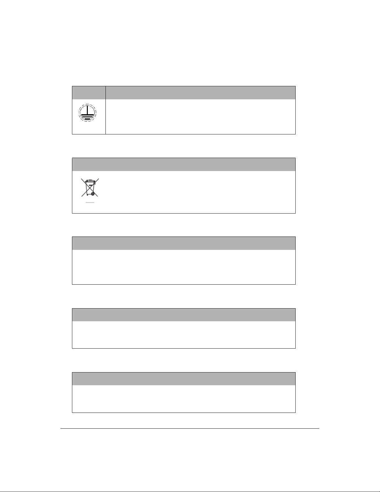
Warning
In 900 On-Line Analyzers, this symbol indicates the protective earth
terminal (ground) for the Analyzer.
Warning
This symbol indicates that to comply with European Union Directive
2002/96/EC for waste electrical and electronic equipment (WEEE), the
Analyzer should be disposed of separately from standard waste.
Warning
Any operation requiring access to the inside of the Analyzer, including installation of
maintenance items, could result in injury. To avoid potentially dangerous shock,
turn off power and, if possible, disconnect from the power supply before opening
the Analyzer.
Warning
The UV lamp and the display screen contain mercury and may be considered
hazardous material in your local area. Dispose of these items in accordance with
federal, state, or local government regulations.
Warning
Should the UV lamp become broken or damaged it should be handled in
accordance with your organization’s toxic waste handling procedure and disposed
of in accordance with federal, state, or local government regulations.
GE Analytical Instruments ©2009 22 of 236 DLM 90488-01 Rev. A

Warning
To protect against accidental exposure to ultra-violet radiation, do not operate the
UV lamp outside of its protective housing.
Warning
When servicing parts inside the Analyzer, keep hands clear of the reagent syringe
assembly if the Analyzer is powered on. The syringes are controlled by moving
parts that can pinch skin.
Warning
This is a Safety Class I product. It must be must be attached to a grounded power
source.
Warning
If this instrument is used in a manner not specified by GE Analytical Instruments
USA, the protection provided by the instrument may be impaired.
Warning
Hazardous reagents (ammonium persulfate and phosphoric acid) are used in the
Analyzer. The waste stream from the instrument is acidic and must be disposed of
properly. Consult your federal, state, and local government regulations.
Warning
Always stop analysis before turning off or unplugging the Analyzer.
GE Analytical Instruments ©2009 23 of 236 DLM 90488-01 Rev. A

Warning
Make sure the DI water Reservoir is full, particularly when running samples with
high TOC or high salt concentrations. Always “clean-up” the Analyzer by running
low-TOC DI water after running high TOC or salt samples.
Warning
This is a Class A product. In a domestic environment, this product may cause
electromagnetic interference in which case the user may be required to take
adequate measures to correct the interference.
Warning
For performance within specifications on ozonated water systems, an Ozone
Destruct Kit must be purchased from GE Analytical Instruments and installed
according to instructions.
Warning
To avoid false TOC readings and possible damage to the Analyzer, always make
sure the sample inlet is open and the DI water reservoir is filled before starting
analysis.
GE Analytical Instruments ©2009 24 of 236 DLM 90488-01 Rev. A

Español
Advertencia
Este símbolo del instrumento indica que el usuario debe consultar el
manual para ver las instrucciones de manejo
Advertencia
El sistema IOS y el puerto del vial contienen dos agujas afiladas
diseñadas para perforar los tabiques de los viales que contienen las
muestras. No coloque los dedos ni ningún material que no sea
adecuado en el sistema IOS ni en el puerto del vial.
Advertencia
En los analizadores portátiles y de laboratorio 900, para disponer en
todo momento de protección frente al peligro de incendio, sustituya
los fusibles por otros del mismo tipo y capacidad.
Advertencia
En los analizadores portátiles y en línea 900, el agua del sistema IOS
puede estar caliente. Antes de insertar un vial en el sistema IOS, abra
la puerta deslizándola y espere durante 30 segundos a que la muestra
se vacíe por completo. Si inserta un vial antes de que se vacíe es
posible que agua potencialmente caliente se proyecte fuera del
sistema IOS.
GE Analytical Instruments ©2009 25 of 236 DLM 90488-01 Rev. A

Advertencia
En los analizadores en línea 900, este símbolo indica el terminal de
protección a tierra (masa) del analizador.
Advertencia
Este símbolo indica que para cumplir la Directiva 2002/96/CE de la
Unión Europea sobre residuos de aparatos eléctricos y electrónicos
(RAEE), el analizador debe desecharse por separado de los residuos
normales.
Advertencia
Toda operación que requiera el acceso al interior del analizador, incluida
la instalación de los elementos de mantenimiento, puede causar daños personales.
Para evitar descargas potencialmente peligrosas, apague el analizador y, si es
posible, desconéctelo de la fuente de alimentación antes de abrirlo.
Advertencia
La lámpara UV y la pantalla de visualización contienen mercurio, por lo que es
posible que se consideren materiales peligrosos en su zona local. Deseche estos
elementos de acuerdo con la normativa federal, del estado o del gobierno local.
Advertencia
Si se rompiese la lámpara UV o resultase dañada, deberá tratarse de acuerdo con
el procedimiento de tratamiento de residuos tóxicos de la organización y
desecharse de acuerdo con la normativa federal, del estado o del gobierno local.
GE Analytical Instruments ©2009 26 of 236 DLM 90488-01 Rev. A

Advertencia
Como protección frente a la exposición accidental a la radiación ultravioleta, no
maneje la lámpara UV fuera de su alojamiento protector.
Advertencia
Cuando esté realizando el mantenimiento de piezas situadas en el interior
del analizador, no coloque nunca las manos en el ensamblado de jeringas de
reactivos si el analizador está encendido. Las jeringas están controladas por piezas
móviles que pueden atravesar la piel.
Advertencia
Este producto es de clase de seguridad I. Debe conectarse a una fuente de
alimentación con toma de masa.
Advertencia
Si este instrumento se utiliza de una manera no especificada por GE Analytical
Instruments USA, la protección ofrecida por el instrumento puede verse reducida.
Advertencia
El analizador utiliza reactivos peligrosos (persulfato de amonio y ácido fosfórico). El
flujo de residuos del instrumento es ácido y deberá desecharse adecuadamente.
Consulte la normativa federal, del estado o del gobierno local.
Advertencia
Detenga siempre el análisis antes de apagar o desconectar el analizador.
GE Analytical Instruments ©2009 27 of 236 DLM 90488-01 Rev. A
Advertencia
Asegúrese de que el depósito de agua DI está lleno, en especial al procesar
muestras con altas concentraciones de sal o carbono orgánico total (TOC). “Limpie”
siempre el analizador procesando agua DI con bajos niveles de TOC después de
procesar muestras con niveles altos de sal o de TOC.
Advertencia
Este producto es de clase A. En entornos domésticos, puede producir interferencias
electromagnéticas en cuyo caso puede que se le requiera al usuario que tome las
medidas oportunas para corregir la interferencia.
Advertencia
Para trabajar dentro de las especificaciones en sistemas de agua ozonizada, se
deberá adquirir un kit de destrucción de ozono a GE Analytical Instruments e
instalarlo de acuerdo con las instrucciones.
Advertencia
Para evitar falsas lecturas de TOC y posibles daños al analizador, asegúrese
siempre de que la entrada de muestras está abierta y de que el depósito de agua
DI está lleno antes de iniciar el análisis.
Français
GE Analytical Instruments ©2009 28 of 236 DLM 90488-01 Rev. A
Avertissement
Ce symbole placé sur l’instrument indique que l’utilisateur doit se
rapporter au manuel pour les instructions de fonctionnement.
Avertissement
Le système IOS et le porte-fiole contiennent deux aiguilles acérées
conçues pour percer les septa des fioles. N’introduisez ni vos doigts, ni
aucun objet dans le système IOS System ou le porte-fiole.
Avertissement
Pour une protection continue contre les risques d’incendie, remplacez
les fusibles dans les analyseurs portables et de laboratoire 900 par
des pièces de même type et de même voltage.
Avertissement
Dans les analyseurs portables et en ligne 900, l’eau contenue dans le
système IOS peut être brûlante. Avant d’insérer une fiole dans le
système IOS, ouvrez la porte en la faisant coulisser et attendez 30
secondes que l’eau s’écoule complètement. L’insertion d’une fiole
avant le séchage complet peut entraîner une projection d’eau chaude
en dehors du système IOS.
GE Analytical Instruments ©2009 29 of 236 DLM 90488-01 Rev. A
Avertissement
Sur les analyseurs en ligne 900, ce symbole spécifie la borne
de protection (mise à la terre) de l’analyseur.
Attention
Ce symbole indique que, pour être en conformité avec la directive
européenne 2002/96/CE relative à l’élimination des appareils
électriques et électroniques (Waste Electrical and Electronic
Equipment, WEEE), l’analyseur doit être mis au rebut séparément
des déchets courants.
Avertissement
Toute opération nécessitant d’accéder à l’intérieur de l’analyseur, y compris
l’installation d’éléments de maintenance, peut entraîner des blessures. Afin d’éviter
tout choc électrique potentiellement dangereux, mettez l’analyseur hors tension et,
si possible, débranchez-le de la prise d’alimentation avant de l’ouvrir.
Avertissement
La lampe UV et l’écran contiennent du mercure et peuvent ainsi être considérés
comme des éléments dangereux dans votre secteur. Jetez ces éléments
conformément aux réglementations locales en vigueur.
Avertissement
Si la lampe UV venait à être cassée ou endommagée, elle devrait être remplacée
conformément à la procédure en vigueur dans votre entreprise pour le
remplacement de produits toxiques.
GE Analytical Instruments ©2009 30 of 236 DLM 90488-01 Rev. A
 Loading...