

Page 1
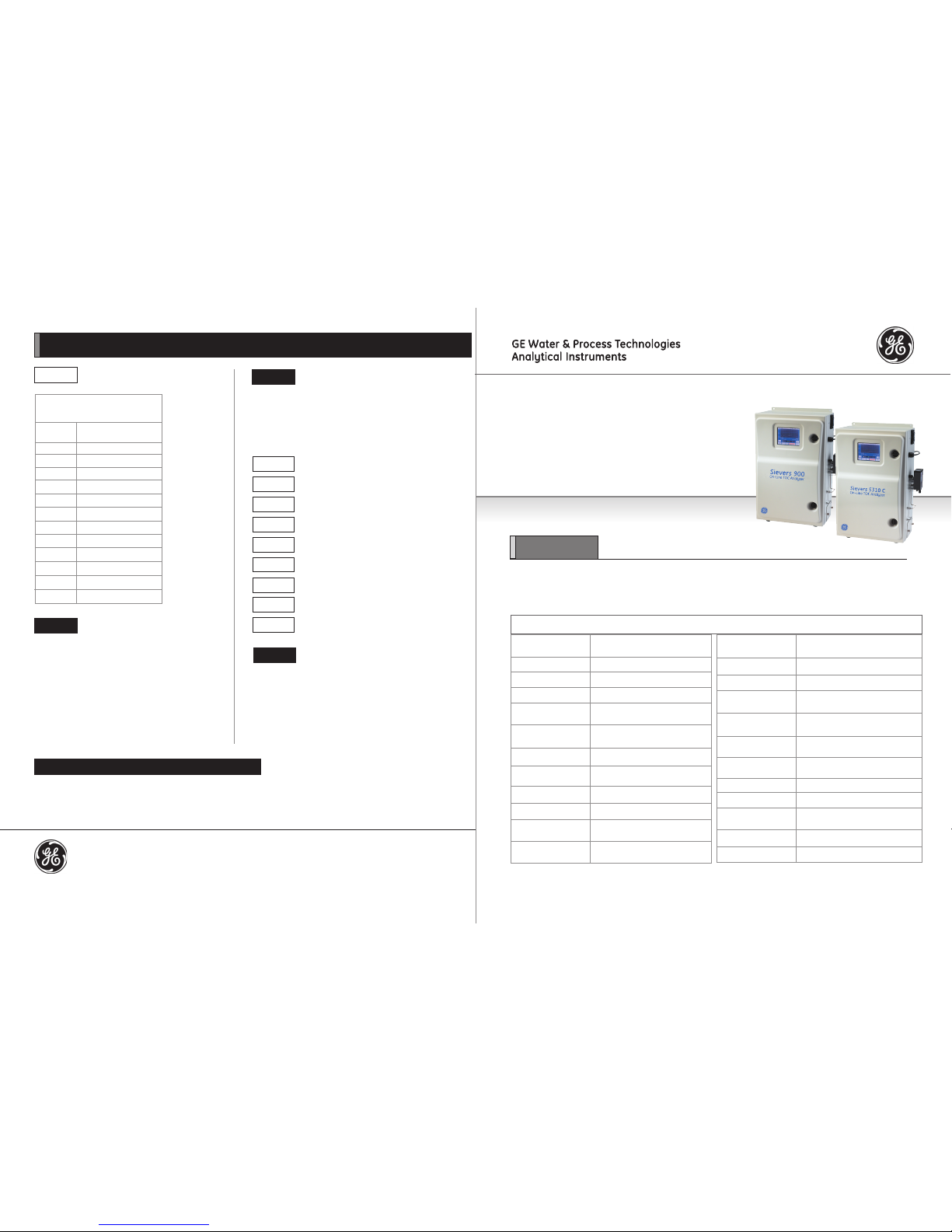
Sievers 900 and 5310 C
On-Line TOC Analyzers
Quick Start Guide
IMPORTANT
For more detailed instructions, you can download manuals for the Sievers 900 On-Line TOC Analyzer, the
Sievers 5310 C On-Line TOC Analyzer, or the Sievers Inorganic Carbon Remover (ICR) from our Web site. Go to
www.geinstruments.com, click Library, then Manuals, and make your selection.
Sievers 900 and 5310 C On-Line TOC Analyzer Installation Instructions (continued)
System Specications*
Linear range (900)
Linear range (5310 C)
Precision
Accuracy
Analysis time
0.03 ppb - 50 ppm TOC
4 ppb - 50 ppm TOC
<1% of RSD
±2% or ±0.5 ppb, whichever is greater
4 minutes
Sample ow rate
(nominal)
Power requirements
Fuses
Analysis mode: 0.5 mL/min
Fast Flush (between samples): 1.0 mL/min
100-240 ± 10% VAC, 50 watts, 50/60 Hz
No user-replaceable fuses; built-in circuit
breaker
Sample temperature
Ambient temperature
Sample pressure
(in iOS System)
Maximum relative
humidity
1 ºC to 95 ºC**
10 ºC to 40 ºC
Up to 250 psig**
Up to 95%, noncondensing
Maximum altitude 3,000 m (9,843 ft)
Installation/Overvoltage
category
Serial (RS-232), USB, parallel printer port,
4-20 mA output, two alarms, binary output
II
Calibration stability Typically stable for 12 months
Chemical reagents
(prepackaged)
300 mL acid; 300 mL or 150 mL oxidizer
Safety certicates CE, ETL listed. Conforms to UL Std. 61010-1
Certied to CSA C22.2 No. 61010-1
Pollution degree
2
Display
Color, touch-sensitive LCD
Weight
16.9 kg (37.2 Ibs)
* Stated analytical performance is achievable under controlled laboratory conditions that minimize operator and standards errors.
** If the sample temperature and pressure are above 60 ºC and 100 psi, the 900 and 5310 C On-Line Analyzer models with the stainless steel iOS is required.
Outputs
Step 6 C
Install the Analog outputs and alarms
(continued).
Step 9
Flush the Analyzer
Before placing the Analyzer into normal operation, you should
perform a reagent ush to remove any gas bubbles that may
have formed in the reagent lines; you should then leave the
Analyzer powered on for 12 hours to allow the DI water reservoir
to properly complete rinse down action.
Size
62.4 cm height x 45.2 cm width x 26.4 cm
depth (24.6 in x 17.8 in x 10.4 in)
Required sample line
ow rate
30 mL - 300 mL/min (for On-Line Mode)
Normal operating
environment
Intended for indoor use only; avoid
sunlight
IP Rating
IP 45
Step 7
Connect the inlet system and waste outlet.
1. Connect the 1/4” Teon tubing with the capsule or inline
lter to the sample inlet on the iOS System. Tighten 1/4 turn
past nger-tight with a 9/16” open-end wrench. Do not over-
tighten the nut.*
* For raw water and heavy particulates applications, additional
pre-ltration is required. Please contact GE Analytical Instruments
if you need recommendations.
2. Connect the 3/4” OD waste line tubing to the waste outlet on
the iOS System by sliding the tubing over the barb tting.
Table 3: Serial and 4-20 mA
Inputs and Outputs (TB3)
12
4-20 mA ( - output)
11
4-20 mA ( + output)
10
Not used
9
Not used
8
Reserved
7
Reserved
6
Reserved
5
Not used
4
Serial (In)
3
Serial (Out)
Pin Number
(from left)
Output
2
Serial (Ground)
1
Not used
Step 8
Congure basic Analyzer settings.
Before using the Analyzer, you will need to congure various basic
settings. Some of these settings will not need to be changed again,
unless yo u move the Analyzer or recongure the operational environment. Refer to the 900 or 5310 C On-Line Operation and Maintenance
Manual for complete details.
Step 8 B
Enable password protection.
Step 8 C
Set the clock and time zone.
Step 8 D
Name the Analyzer location (optional).
Step 8 E
Set reagent expiration dates.
Step 8 F
Set up the data history.
Step 8 G
Set up the printer (pptional).
Step 8 H
Export or print constants.
Step 8 A
Power the Analyzer on.
Step 8 I
Set up data I/O.
©2016. General Electric Company. All Rights Reserved.
DQS 96003-01 Rev A
Americas: T 800 255 6964, 303 444 2009 | geai@ge.com
Europe/Middle East/Africa: T 44 (0) 161 864 6800 | geai.europe@ge.com
Asia Pacic: geai.asia@ge.com
www.geinstruments.com
For more detailed instructions, you can download operation and maintenance manuals for the Sievers 900 On-Line Analyzer, the Sievers
5310 C On-Line TOC Analyzer, and the 900 Inorganic Carbon Remover (ICR) from our Web site. Go to www.geinstruments.com, click Library,
then Manuals, and make your selection.
Where to Find Operation and Maintenance Manuals
Page 2
Sievers 900 and 5310 C Series On-Line TOC Analyzer Installation Instructions
To avoid exposure to the chemical reagents, wear
acid-resistant gloves, protective clothing, and safety
goggles or a face shield when changing the reagent
supplies.
Reagent containers are for single-use only –
DO NOT REFILL. Relling or reusing reagent containers
will void all Analyzer and parts warranties and nullify
any performance claims.
Operation of the Analyzer without the in-line lter
on the sample inlet line will damage the Analyzer
and void the warranty. To avoid damaging the
Analyzer, install the lter and replace the lter
element as needed.
See the separate “Warnings” document for
additional important information.
Step 1
Unpack and inspect the Analyzer.
Step 2
Complete the identication records.
Step 3
Select a location for the Analyzer. Refer to the System
Specications chart.
WARNINGS
To avoid false TOC readings and possible damage to
the Analyzer, always make sure the sample is owing
through the iOS System and the DI water reservoir is
lled before starting analysis.
Figure 1 - Reagent cartridges
NOTE: Hazardous reagents (ammonium persulfate
and phosphoric acid) are used in the Analyzer.
Before installing the reagents, please read the
Material Safety Data Sheets (MSDS) contained in
a pouch on the top of the reagent shipping box
for proper handling precautions and spill or leak
procedures.
Step 5
Fill the DI water reservoir.
1. Remove the rubber inlet cover on the DI water reservoir.
2. Slide the bottle nozzle into the inlet hole, and gently squeeze the
bottle. Be sure to ll the reservoir until the water reaches the ll
line, just below the inlet.
Step 4
Install the reagent cartridges. (See Figure 1.)
The oxidizer and acid reagents are shipped from GE Analytical
Instruments in specic packaging for safety in transit. Carefully
read the attached MSDS sheets prior to opening the packaging.
Within the packaging are two reagent cartridges. Each reagent
cartridge is identied with labels that indicate which cartridge
contains ammonium persulfate and which cartridge contains
phosphoric acid.
1. Locate the acid supply line, indicated by the Acid label. Attach
the PEEK nut to the acid reagent container and tighten nger-
tight.
2. Slide the valve on the acid container to the open position by
pushing the green button all the way in. Refer to the labeling on
the container for proper positioning.
Step 6
Install accessories and cables.
If you will be using a 900 ICR unit with your conguration, make
sure it is installed. Follow the complete set of operation instructions
in the ICR Operation and Maintenance Manual. (See downloading
instructions on the back page of this Quick Start Guide.)
Step 6 A
Install the 900 Inorganic Carbon Remover (ICR).
Installation of the Sievers 900/5310 C On-Line TOC Analyzer requires an
external source of AC power connected to the enclosure using a watertight conduit connector. The electrical connection should be performed
by a qualied electrician. An external switch or circuit breaker is recommended to facilitate maintenance and servicing of the Analyzer. It should
be installed near the Analyzer and be clearly marked as the disconnecting
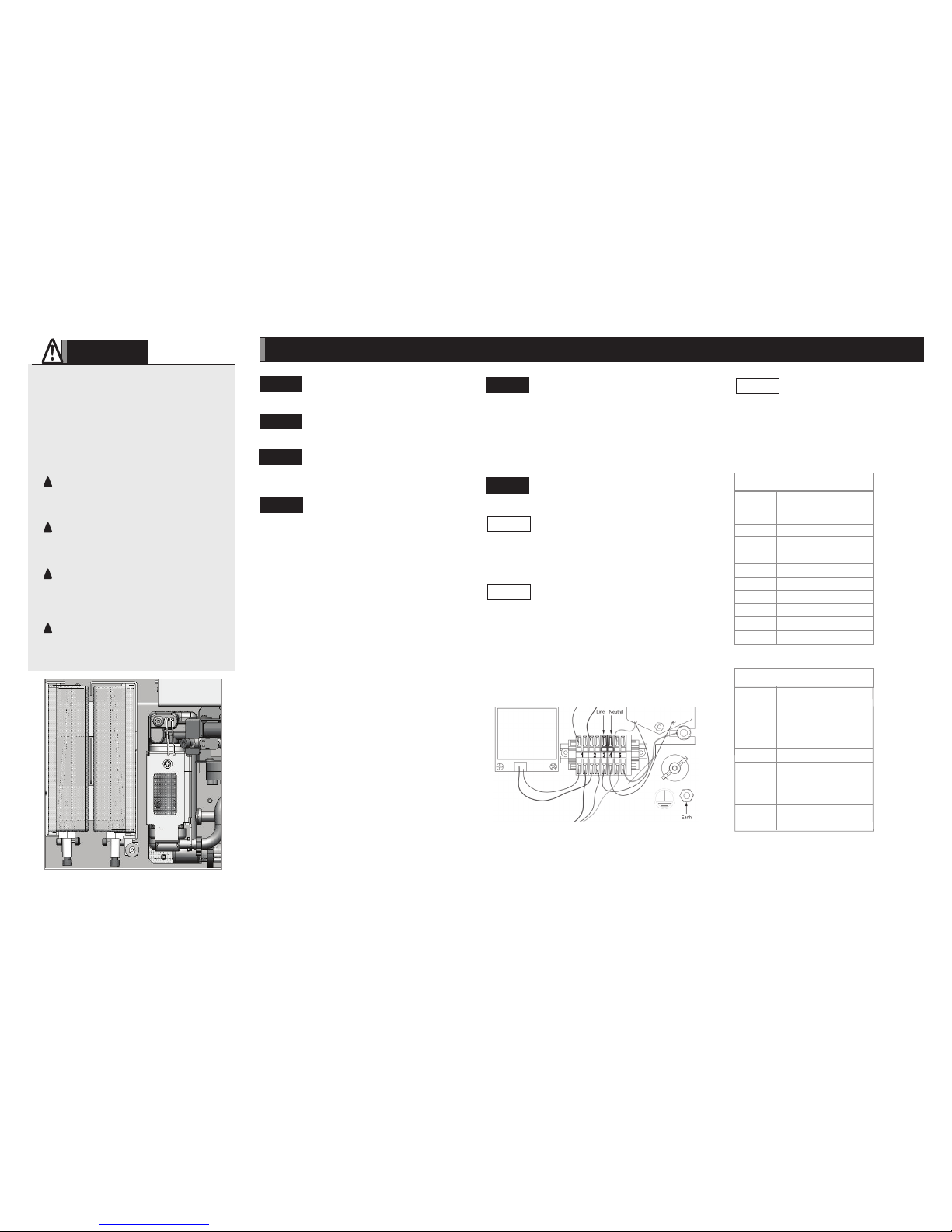
device for the Analyzer. (See Figure 2.)
NOTE: Before installing any wiring inside the Analyzer, put on a
grounding strap for ESD protection.
Step 6 B
Connect to a power supply.
The Analyzer has three terminal blocks, arranged horizontally
in the electrical enclosure inside the Analyzer; remove the
enclosure cover by loosening the front screws. Consult Tables
1–3 for a list of functions on each terminal block. The output
and alarm connections should be installed by a qualied
electrician. Refer to the 900 or 5310 C On-Line Operations and
Maintenance Manual for complete details.
Step 6 C
Install the analog outputs and alarms.
3. Slide the acid container into the reagent enclosure, with the
valve pointing down and toward the front of the reagent
enclosure.
4. Locate the oxidizer supply line, indicated by the Oxidizer
label. Attach the PEEK nut to the oxidizer container and
tighten nger-tight.
5. Slide the valve on the oxidizer container to the open
position by pushing the green button all the way in. Refer
to the labeling on the container for proper positioning.
6. Slide the oxidizer container into the reagent enclosure, with
the valve pointing down and toward the front of the reagent
enclosure.
Table 1: Inputs and Outputs (TB2)
10 Ground, for binary input
9 24 V (+ output, for binary input)
8 Start/Stop - (for binary input)
7 Start/Stop + (for binary input)
6 Alarm 2 (NO*) (output)
5 Alarm 2 (NC*) (output)
4 Alarm 2 (Common) (output)
3 Alarm 1 (NO*) (output)
2
Alarm 1 (NC*) (output)
1
Alarm 1 (Common) (output)
* NC = normally closed *NO = normally open
Pin Number
(from left)
Input/Output
Table 2: Inputs and Outputs (TB1)
8 900 Lab: Reserved
5310 C Lab: Stream 1 - (input) 0
7 900 Lab: Reserved
5310 C Lab: Stream 1 + (input)
6 End of Batch (NO*) (output)
5 End of Batch (NC*) (output)
4 End of Batch (Common) (output)
3 Reserved
2
Reserved
1 Reserved
* NC = normally closed *NO = normally open
Pin Number
(from left)
Input/Output
Figure 2 - Wiring AC Power Conduit (Arrows indicate connection points.)
 Loading...