

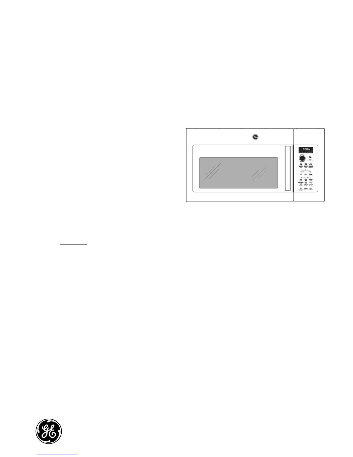
GE PVM9179*K Series Training Bulletin
GE Appliances
Training Bulletin
June 2016
Microwave/OTR Convection
TB13-16
New PVM9179_K Convection Microwave
Features:
• Convection assembly is located on left side
of oven cavity.
• Chef Connect
• Dial and touchpad controls
• 300 CFM exhaust vent fan
• LED cooktop light
• Demo mode
• 1.7 cu. ft. enameled cavity
• 950 watts
• Charcoal filter included for recirculating
configuration
• Removable oven rack and convection rack
Use the complete model number (including engineering digit) when looking up parts.
This Training Bulletin covers some of the differences between the new and previous versions of
the PVM9179.
GE Appliances
Louisville, KY 40225
1
TB13-16

Demo Mode -The DEMO MODE is initiated by holding the “POWER LEVEL” and “START/PAUSE” pads at
the same time for a full 3 seconds. This mode can only be entered during the initial “PRESS CLOCK”
display that occurs when the microwave powers up after a (>25 seconds) power outage.
Error Message – These messages scroll across the display if an error is detected. The control will also
beep 3 times and repeat the signal after approximately 1 minute until power is removed from the
microwave.
Scrolled message Possible cause
• KEYPAD SHORTED -- SERVICE MAY BE NEEDED
• OPEN STEAM SENSOR -- SERVICE MAY BE NEEDED
• SHORTED STEAM SENSOR -- SERVICE MAY BE NEEDED
• OPEN THERMAL SENSOR -- SERVICE MAY BE NEEDED
• SHORTED THERMAL SENSOR -- SERVICE MAY BE NEEDED
• DAMPER STUCK -- SERVICE MAY BE NEEDED
• ABNORMAL HIGH TEMP -- SERVICE MAY BE NEEDED
Keypanel shorted continuously for over 60 sec.
Open humidity sensor
Shorted humidity sensor
Open thermal sensor
Shorted thermal sensor
Stuck damper
If oven temperature is over the set temperature
for 30 minutes.
Performance Test – For all microwave performance tests, measure the line voltage under load. This test
is based on normal voltage variations of 108vac to 132vac. Low voltage will lower output power and
temperature rise.
1. Place beaker WB64X73 containing one liter of water (59° F~ 75 ° F) on turntable and record the
starting water temperature with an accurate thermometer. (DO NOT USE ANY OTHER LOAD OR DISH
AS RESULTS WILL VARY FROM STANDARD)
2. Set time cook for 2 minutes and 3 seconds on HIGH.
3. Turn on the oven.
4. Record the end water temperature.
The minimum difference between the initial and ending temperature should be:
40 ° F @ 120vac
Sensor Cooking (humidity/gas)
All sensor cooking functions use a gas sensor which detects both humidity (steam) and hydrocarbons (food
odors) during the cooking process. Before conducting a sensor test, ensure the microwave has been
plugged into power for at least 5 minutes. This allows the sensor heater to reach proper temperature.
Sensor Test
Press and hold the POWER LEVEL and REHEAT pads at the same time. The display will show a number.
• 15-185 - Normal
• Less than 6 - Indicates a shorted sensor, wiring or main board.
• 213 or higher - Indicates an open sensor, wiring or main board.
Only the heater terminals (BLACK and RED leads) can be checked with an ohmmeter ~30Ω
DO NOT ATTEMPT TO CHECK THE OTHER SENSOR TERMINALS WITH AN OHMMETER AS DAMAGE TO
THE SENSOR CAN OCCUR.
2
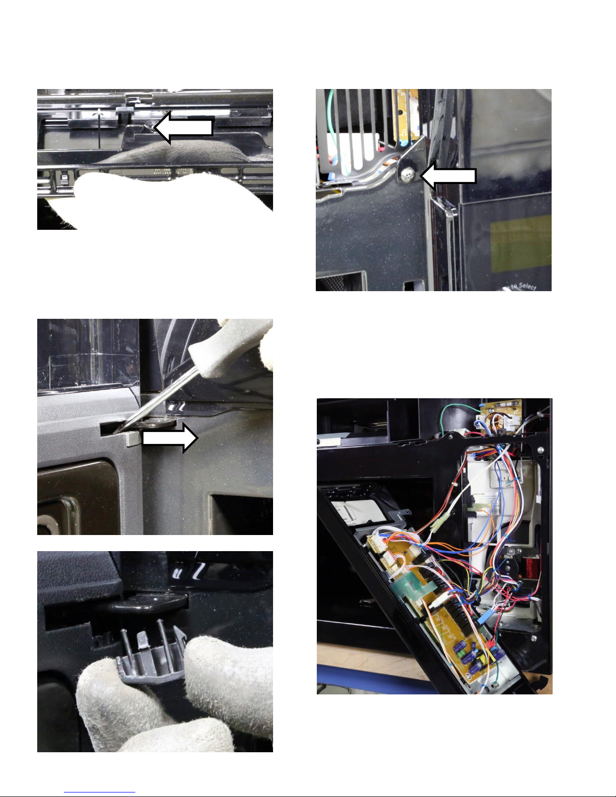
Component Access
Grill – Remove 2 top screws and slide grill to left to
disengage tabs.
tab
Door –Using a small screwdriver, depress the tab
on the end cap under the top hinge to remove the
end cap. Lift up on the door to disengage the door
posts from the hinges.
Control – Remove grill, remove screw and lift
control up to disengage tabs.
Control can be slid up and out of mounting tabs
and rotated to the left for access to the connectors.
Bottom of end cap shown
3
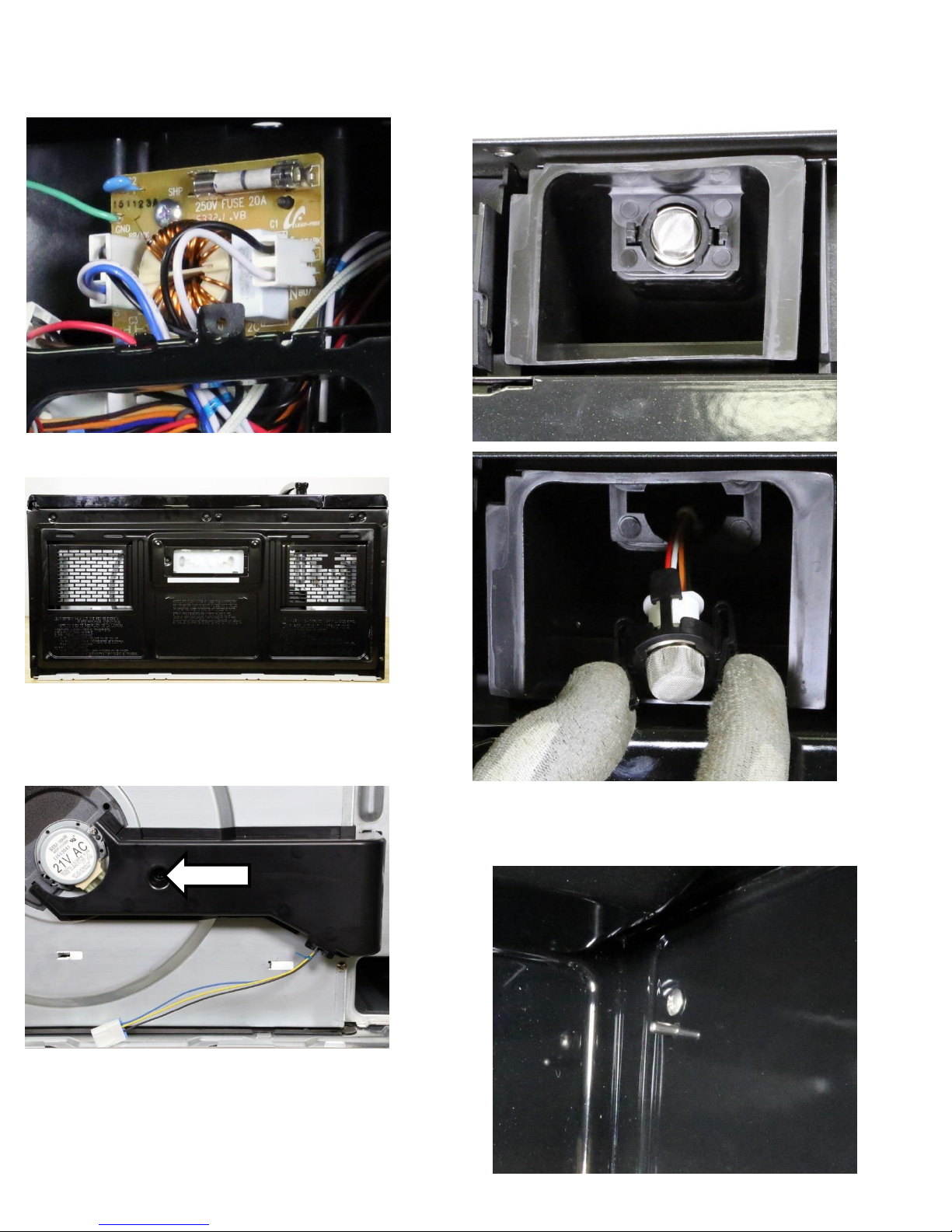
Fuse – Remove grill and remove slotted grill to
access noise filter board and the fuse mounted to it.
Bottom – Remove seven screws.
Sensor (humidity/gas) – Remove the grill, squeeze
tabs on each side of the sensor and pull forward to
disconnect plug.
Turntable motor – Remove the bottom and the
screw that secures air duct. One screw secures the
motor along with one tab.
Turntable spindle – Remove the bottom and the
turntable motor to remove turntable spindle. (not
shown)
Oven sensor – Remove the case. From inside the
oven cavity remove the screw which secures to a
nut behind the sensor.
4
 Loading...