

GE PV977N2SS, PV977N1SS Owner’s Manual

Safety Instructions ............ 2
Operating Instructions
Light Controls ....................4
Vent Controls ....................4
Care and Cleaning
Metal Grease Filter ...............5
Charcoal Filter ...................5
Stainless Steel Surfaces ..........6
Light Bulbs .......................6
Installation Instructions
Installation Preparation ...........8
Vented to the Outside ...........16
Recirculating ....................21
Troubleshooting Tips ........27
Consumer Support
Warranty ....................... 29
Consumer Support .............. 30
Owner’s Manual and
Installation Instructions
PV977
English/Español
Island Chimney
Vent Hoods
Write the model and serial numbers here:
Model # ______________________
Serial # _______________________
You can find them on a label on the inside
of the hood.
49-80550-4 03-16 GE
IMPORTANT SAFETY INFORMATION.
READ ALL INSTRUCTIONS BEFORE USING.
This is the safety alert symbol. This symbol alerts you to potential hazards that can kill or hurt you
and others. All safety messages will follow the safety alert symbol and the word “DANGER”, “WARNING”, or
´&$87,21µ7KHVHZRUGVDUHGHILQHGDV
Indicates a hazardous situation which, if not avoided, will result in death or serious injury.
DANGER
WARNING
Indicates a hazardous situation which, if not avoided, could result in death or serious injury.
CAUTION
Indicates a hazardous situation which, if not avoided, could result in minor or moderate injury.
SAFETY PRECAUTIONS
WARNING
SHOCK OR INJURY TO PERSONS, OBSERVE THE
FOLLOWING:
A. Use this unit only in the manner intended by the
manufacturer. If you have questions, contact the
manufacturer.
B. Before servicing or cleaning unit, switch power off at
service panel and lock the service disconnecting means
to prevent power from being switched on accidentally.
When the service disconnecting means cannot be locked,
securely fasten a prominent warning device, such as a
tag, to the service panel.
C. Do not use this unit with any solid-state speed control
device.
D. This unit must be grounded.
CAUTION
use to exhaust hazardous or explosive materials and
vapors.
CAUTION
exhaust air, be sure to duct air outside. Do not vent
exhaust air into spaces within walls or ceilings or into
attics, crawl spaces or garages.
TO REDUCE THE RISK OF FIRE, ELECTRIC
For general ventilating use only. Do not
To reduce risk of fire and to properly
WARNING
PERSONS IN THE EVENT OF A RANGE TOP GREASE
FIRE, OBSERVE THE FOLLOWING*:
A. SMOTHER FLAMES with a close-fitting lid, cookie sheet
or metal tray, then turn off the burner. BE CAREFUL TO
PREVENT BURNS. If the flames do not go out immediately,
EVACUATE AND CALL THE FIRE DEPARTMENT.
B. 1(9(53,&.83$)/$0,1*3$1³<RXPD\EHEXUQHG
C.'212786(:$7(5LQFOXGLQJZHWGLVKFORWKVRUWRZHOV³
a violent steam explosion will result.
D.8VHDQH[WLQJXLVKHU21/<LI
1.<RXNQRZ\RXKDYHD&ODVV$%&H[WLQJXLVKHUDQG\RX
already know how to operate it.
2. The fire is small and contained in the area where it
started.
3. The fire department is being called.
4. <RXFDQILJKWWKHILUHZLWK\RXUEDFNWRDQH[LW
* Based on “Kitchen Fire Safety Tips” published by NFPA.
TO REDUCE THE RISK OF INJURY TO
READ AND SAVE THESE INSTRUCTIONS
2
49-80550-4
GEAppliances.com
SAFETY PRECAUTIONS
WARNING
TO REDUCE THE RISK OF A RANGE TOP
GREASE FIRE:
A. Never leave surface units unattended at high settings.
Boilovers cause smoking and greasy spillovers that may
ignite. Heat oils slowly on low or medium settings.
B. Always turn hood ON when cooking on high heat or
when flambéing food (i.e. Crepes Suzette, Cherries Jubilee,
Peppercorn Beef Flambé).
C. Clean ventilating fans frequently. Grease should not be
allowed to accumulate on fan or filter.
D. Use proper pan size. Always use cookware appropriate
for the size of the surface element.
WARNING – TO REDUCE THE RISK OF
FIRE, ELECTRIC SHOCK OR INJURY TO PERSONS,
OBSERVE THE FOLLOWING:
A. Installation work and electrical wiring must be done
by qualified person(s) in accordance with all applicable
codes and standards, including fire-rated construction.
B. Sufficient air is needed for proper combustion and
exhausting of gases through the flue (chimney) of fuel
burning equipment to prevent back drafting. Follow
the heating equipment manufacturer’s guidelines
and safety standards, such as those published by the
National Fire Protection Association (NFPA), the American
Society for Heating, Refrigeration and Air Conditioning
Engineers (ASHRAE) and the local code authorities. When
applicable, install any makeup (replacement) air system
in accordance with local building code requirements. Visit
GEAppliances.com for available makeup air solutions.
C. When cutting or drilling into wall or ceiling, do not
damage electrical wiring and other hidden utilities.
D. Ducted fans must always be vented to the outdoors.
F. Turn off breaker to adjacent rooms while working.
WARNING
ONLY METAL DUCTWORK.
TO REDUCE THE RISK OF FIRE, USE
■ Do not attempt to repair or replace any part of your hood
unless it is specifically recommended in this manual.
All other servicing should be referred to a qualified
technician.
49-80550-4
READ AND SAVE THESE INSTRUCTIONS
3
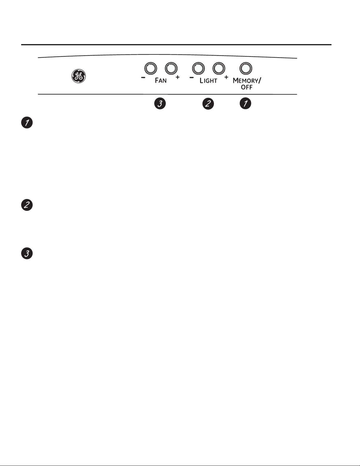
Using the hood controls.
MEMORY/OFF.7RVHWWKHPHPRU\
A. Press the MEMORY/OFF button.
B. Set your desired fan and light settings.
C. Press the MEMORY/OFF button again to save these
settings.
With your desired settings in memory, press the
MEMORY/OFF button to restore the fan and light
levels to their saved settings. These settings will
remain in memory until they are changed or loss of
power occurs.
To turn off the hood, press the MEMORY/OFF button.
LIGHT. Press + or – to increase or decrease light level
to desired setting. There are 2 light levels (LOW, HIGH)
and OFF. If you continue to press the + or – buttons,
the light will cycle back through the settings.
NOTE: Please check the lamps to ensure only 20W
lamps (maximum) are installed.
FAN. Press + or – to increase or decrease fan level
to your desired setting. There are 4 fan levels (LOW,
MED, HIGH, BOOST) and OFF. If you continue to press
the + or – buttons, the fan will cycle back through the
settings.
NOTE: There is an audible “beep” each time a button
is pressed. This is normal.
NOTE: The collars around the buttons will illuminate
when pressed. This is normal. The collars will
automatically turn off if the hood is turned off.
HEAT SENSOR:
This hood is equipped with a heat sensor that will turn
on the fan if excessive temperatures are detected (over
Û&Û)DERYHWKHFRRNLQJVXUIDFH7KHKRRGZLOO
return to its normal operation once the heat sensor detects
WHPSHUDWXUHVEHORZÛ&Û)
NOTE: If the hood is OFF or on LOW fan speed, the
WHPSHUDWXUHVDERYHÛ&Û)DUHGHWHFWHGWKHQWKHIDQ
will automatically adjust to MEDVSHHG<RXPD\DGMXVW
the fan speed to HIGH or BOOST, but you will not be able
to adjust the fan speed to LOW or OFF until temperatures
EHORZÛ&Û)DUHGHWHFWHG
NOTE: The collars around the buttons may not illuminate if
the heat sensor is activated. This is normal.
4
49-80550-4

Care and cleaning of the vent hood. GEAppliances.com
Be sure electrical power is off and all surfaces are cool before cleaning or servicing any part of the vent hood.
Locking tab handle
Metal Grease Filter
The metal filter traps grease released
by foods from the cooktop. The filter
also helps prevent flames (from food,
grease) from damaging the inside of
the hood.
)RUWKLVUHDVRQWKHILOWHUPXVW$/:$<6
be in place when the hood is in use.
The grease filter is dishwashersafe and should be cleaned every 6
months, or as needed.
Charcoal Filter
For recirculating installation only
If the model is not vented to the outside,
the air will be recirculated through a
disposable charcoal filter that helps
remove smoke and odors.
The charcoal filter should be replaced
when it is noticeably dirty or discolored
(usually after 6 to 12 months, depending
on hood usage).
NOTE: DO NOT rinse, or put charcoal
filter in an automatic dishwasher.
The charcoal filter cannot be cleaned.
It must be replaced.
Order Charcoal Filter WB02X11348.
To remove:
Pull downward on the filter lock to
release the filter.
To replace:
Fit the tabs at the end of the filter
into the slots in left side of the filter
opening. Lift up the right side of the
filter and push gently until the filter
locks into place. Make sure the filter
lock is in the closed position to secure
the filter.
To clean, swish the filter in hot soapy
water and rinse in clean water or
wash it in the dishwasher. Do not use
abrasive cleansers.
NOTE: Some discoloration will occur in
the dishwasher.
To remove:
1. 5HPRYHWKHPHWDOILOWHU³VHH0HWDO
grease filter section.
2. Remove the charcoal filter by pushing
in on both locking tab handles to
release.
To replace:
1. Insert the charcoal filter into the
opening. Push the locking tab handles
toward the center and release to
engage the locking tabs.
2.5HSODFHWKHPHWDOILOWHU³VHH0HWDO
grease filter section.
49-80550-4
Locking tab handle
To inquire about purchasing
replacement charcoal filters or to find
the location of a dealer nearest you,
SOHDVHFDOORXUWROOIUHHQXPEHU
National Parts Center
800.626.2002
5

Care and cleaning of the vent hood.
Be sure electrical power is off and all surfaces are cool before cleaning or servicing any part of the vent hood.
Stainless Steel Surfaces
Do not use a steel wool pad; it will scratch the
surface.
To clean the stainless steel surface, use warm
sudsy water or a stainless steel cleaner or
polish. Always wipe the surface in the direction
of the brush line. Follow the cleaner instructions
for cleaning the stainless steel surface. Cleaners
with oxalic acid such as Bar Keepers Friend
Soft Cleanser™ will remove surface rust,
tarnish, and small blemishes. To receive a $2.00
coupon for a trial sample of Bar Keepers Friend
Soft Cleanser™ follow the link below or scan
the QR Code.
ZZZEDUNHHSHUVIULHQGFRPJH
Light Bulbs
CAUTION
Allow bulbs to cool before touching.
To change the light bulbs:
1. Remove the lamp lens cover by inserting a
small flat blade screwdriver into each of the
three slots and gently prying it free.
NOTE: Do not remove the outer trim ring
(lamp assembly).
2. Wear gloves. Do not touch the bulb with
your bare fingers. Skin oils can cause early
lamp failure.
3. Grasp the bulb and pull it straight out.
4. Replace with the same wattage. Early bulb
failure and damage to or failure of the
transformer may occur if wattage
is too high.
These 12-volt, 20-watt halogen bulbs with
a G4 base are available at specialty lighting
stores and home building centers.
To order replacement bulb no. WB01X10239,
contact the GE National Parts Center at
1.800.626.2002 or purchase from your local
retailer.
5. Replace lamp lens cover by inserting
the three retaining tabs into the three slots
and pressing firmly in place.
Use only a liquid cleanser free of grit and rub in
the direction of the brush lines with a damp soft
sponge.
To inquire about purchasing stainless steel
appliance cleaner or polish, or to find the
location of a dealer nearest you, please call our
WROOIUHHQXPEHU
National Parts Center
800.626.2002
GEApplianceParts.com
Use a small flat blade screwdriver
to remove the lamp lens cover.
Bulb
Outer trim ring
(lamp assembly)
Do not remove
Tab
Removable inner
lamp lens cover
127(0DNHVXUHWKHWDEVDUHLQVHUWHGLQWRWKHVORWV
6
49-80550-4
Installation
Island Chimney Vent Hood
Instructions
Questions? Call 800.GE.CARES (800.432.2737) or Visit our Website at: GEAppliances.com
BEFORE YOU BEGIN
Read these instructions completely and carefully.
•
IMPORTANT ³ Save these instructions
for local inspector’s use.
•
IMPORTANT ³ Observe all governing
codes and ordinances.
•
Note to Installer – Be sure to leave these
instructions with the Consumer.
• Note to Consumer – Keep these instructions
for future reference.
• Skill level – Installation of this vent hood requires
basic mechanical and electrical skills.
• Completion time – Approximately
• Proper installation is the responsibility of the
installer.
• Product failure due to improper installation is not
covered under the Warranty.
CAUTION
vent hoods and to reduce the risk of personal injury
or damage to the product,
TWO PEOPLE ARE REQUIRED FOR PROPER
INSTALLATION.
Due to the weight and size of these
4 to 6 hours
FOR YOUR SAFETY:
WARNING
switch power off at service panel and lock the
service disconnecting means to prevent power
from being switched on accidentally. When the
service disconnecting means cannot be locked,
securely fasten a prominent warning device, such
as a tag, to the service panel.
Before beginning the installation,
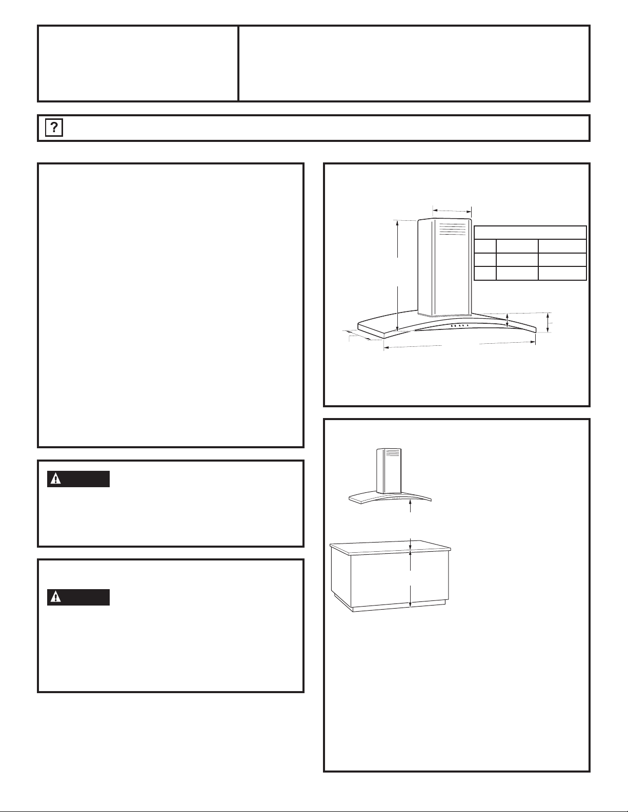
PRODUCT DIMENSIONS
µ
*Height to Ceiling
Vented Recirculating
*Height to
ceiling
µ
* For supplied duct cover ceiling height for vented
installation and recirculating installation, refer to
the table on page 12.
µ
Min µ µ
Max µ µ
µ
µ
INSTALLATION CLEARANCES
These vent hoods are
designed to be installed
onto a wall with no above
cabinets.
24” Required Min.
36” Recommended Max.
36” Typical
and 36” recommended maximum above the
cooking surface. The hood installation height
above the cooking surface depends upon ceiling
height and duct cover limitations. The telescopic
duct cover conceals the ductwork running from
the top of the hood to the ceiling.
NOTE: Installation height should be measured from
the cooking surface to the lowest part of the hood.
This hood must be installed onto a wall. It can be
vented to the outdoors, or it can be installed for
recirculating operation. Recirculating Kit included
with hood.
• Install these hoods
between the required
24” minimum and
36” recommended
maximum above the
cooking surface.
The vent hood must be
installed between the
required 24” minimum
49-80550-4
7
Installation Preparation
PREPARE TO INSTALL THE HOOD
ADVANCE PLANNING
Duct Install Planning
• Determine the exact location of the vent hood.
• Use rigid metal ductwork only.
• Plan the route for venting exhaust to the outdoors.
To maximize the ventilation performance of the
YHQWV\VWHP
1. Minimize the duct run length and number of
transitions and elbows.
2. Maintain a constant duct size.
3. Seal all joints with duct tape to prevent any leaks.
4. Do not use any type of flexible ducting.
• Use the shortest and straightest duct route
possible.
• Install a roof cap with damper at the exterior
opening. Order the cap and any transitions and
length of duct needed in advance.
• When applicable, install any makeup (replacement)
air system in accordance with local building code
requirements. Visit GEAppliances.com for available
makeup air solutions.
Ceiling Framing for Adequate Support
• These vent hoods are heavy. Adequate structural
support must be provided. The ceiling structure
must be capable of supporting the weight of the
hood and any inadvertent user contact loads
(approximately 200 pounds). The hood support
frame will be supported by 2 x 4 cross framing.
• Installation will be easier if the vent hood is
installed before the cooktop or countertop below is
installed.
Duct Covers
• All models are shipped with duct covers. For
supplied duct cover ceiling heights for vented
installation and recirculating installation, refer to
table on page 12.
POWER SUPPLY
IMPORTANT - (Please read carefully)
WARNING
)253(5621$/6$)(7<7+,6$33/,$1&(0867%(
3523(5/<*5281'('
Remove house fuse or open circuit breaker before
beginning installation.
Do not use an extension cord or adapter plug with
this appliance. Follow National Electrical Codes or
prevailing local codes and ordinances.
Electrical Supply
This vent hood must be supplied with 120V, 60Hz,
and connected to an individual, properly grounded
branch circuit, and protected by a 15 or 20 amp
circuit breaker or time delay fuse.
• Wiring must be 2 wire with ground.
• If the electrical supply does not meet the above
requirements, call a licensed electrician before
proceeding.
• Route house wiring in the ceiling, as close to the
installation location as possible. Allow additional
length from ceiling joists to reach the junction box
on the bottom of the hood support frame.
• Connect the wiring to the house wiring in
accordance with local codes.
Grounding Instructions
The grounding conductor must be connected to
a ground metal, permanent wiring system, or an
equipment-grounding terminal or lead on the
hood.
WARNING
The improper connection of equipment-grounding
conductor can result in a risk of electric shock. Check
with a qualified electrician or service representative
if you are in doubt whether the appliance is properly
grounded.
8
49-80550-4

Installation Preparation
PREPARE TO INSTALL THE HOOD
This Hood Must Use an 8” Round Duct.
,W&DQ7UDQVLWLRQWRDµ[µ'XFW
DO NOT use flexible plastic ducting.
NOTE: Any home ventilation system, such as a
ventilation hood, may interrupt the proper flow of
combustion air and exhaust required by fireplaces,
gas furnaces, gas water heaters and other
naturally vented systems. To minimize the chance
of interruption of such naturally vented systems,
follow the heating equipment manufacturer’s
guidelines and safety standards such as those
published by NFPA and ASHRAE. When applicable,
install any makeup (replacement) air system in
accordance with local building code requirements.
Visit GEAppliances.com for available makeup air
solutions.
49-80550-4
9

Installation Preparation
PREPARE TO INSTALL THE HOOD
TOOLS AND MATERIALS REQUIRED
(NOT SUPPLIED)
Safety glasses
Pencil and tape measure
Spirit level
Phillips screwdriver
(OHFWULFGULOOZLWKµ
bits, #2 Phillips head
Hammer
Flashlight
Metal snips
Pliers
REMOVE THE PACKAGING
CAUTION
edges.
• Remove the duct covers.
• Remove the hardware bag, literature package
and other boxed parts.
• Remove and properly discard the protective
plastic wrapping and other packaging materials.
Wear gloves to protect against sharp
Step ladder
UL listed wire nuts
Aluminized
Duct tape
Strain relief for
junction box
:LUHFXWWHUVWULSSHU
Saber saw or Key Hole saw
8” Round metal
duct, length to
suit installation
120V 60Hz. 15 or 20 Amp,
2-wire with ground, properly
grounded branch circuit
10
49-80550-4
Installation Preparation
PREPARE TO INSTALL THE HOOD
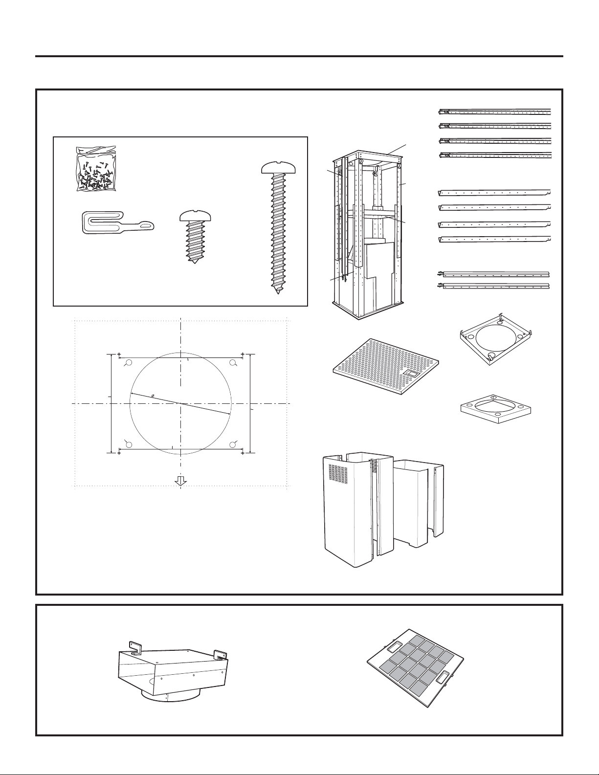
CHECK INSTALLATION HARDWARE
Locate the hardware package packed with the hood and check contents.
HARDWARE PACKAGE
Locate and count
4 Duct cover clips
73 Hood attachment screws
(70 required, 3 extra)
Cutone 1/2" Dia.
WireAccess Hole
asNeeded
8-1/4"To
Centerlineof
PilotHoles
screws
36" HOOD
8-
1
/2
"
TEMPLATE
10-5/16"To
Centerlineof
PilotHoles
4 Wood
screws
Drill3/16" Pilot Holes
Approx.1-1/2" Deep
4Places
Cutone 1/2" Dia.
WireAccess Hole
asNeeded
8-1/4"To
Centerlineof
PilotHoles
C
B
Stainless steel filter
A
D
Upper vertical supports (4)
A
B
E
Lower vertical supports (4)
C
Duct cover supports (2)
D
Ceiling support
E
Cutone 1/2" Dia.
WireAccess Hole
asNeeded
10-5/16"To
Centerlineof
PilotHoles
FRONT OF HOOD
Template
RECIRCULATING KIT (Included)
Cutone 1/2" Dia.
WireAccess Hole
asNeeded
31-14772
Printedin Mexico
Horizontal support
12-08JR
Lower
Upper
Duct covers
49-80550-4
Air deflector
Charcoal filter
11

Installation Preparation
PREPARE TO INSTALL THE HOOD
INSTALLATION CLEARANCES
These vent hoods are designed to be installed onto
a wall with no above cabinets.
• Install these hoods between the required 24”
minimum and 36” recommended maximum
above the cooking surface.
24” Required Min.
36” Recommended Max.
36” Typical
The vent hood must be installed between the
required 24” minimum and 36” recommended
maximum above the cooking surface. The hood
installation height above the cooking surface
depends upon ceiling height and duct cover
limitations. The telescopic duct cover conceals
the ductwork running from the top of the hood to
the ceiling.
NOTE: Installation height should be measured from
the cooking surface to the lowest part of the hood.
This hood must be installed onto a wall. It can be
vented to the outdoors, or it can be installed for
recirculating operation. Recirculating Kit included
with hood.
PV977
Upper Duct Cover 29.92
Lower Duct Cover 25.98
Counter to Hood Height
Actual Ceiling
Height
7’ 11” 24” 24”
8’ 0” 24” to 25” 24” to 25”
8’ 1” 24” to 26” 24” to 26”
8’ 2” 24” to 27” 24” to 27”
8’ 3” 24” to 28” 24” to 28”
8’ 4” 24” to 29” 24” to 29”
8’ 5” 24” to 30” 24” to 30”
8’ 6” 24” to 31” 24” to 31”
8’ 7” 24” to 32” 24” to 32”
8’ 8” 24” to 33” 24” to 33”
8’ 9” 24” to 34” 24” to 34”
8’ 10” 24” to 35” 24” to 35”
8’ 11” 24” to 36” 24” to 36”
9’ 0” 24” to 36” 24” to 36”
9’ 1” 24” to 36” 24” to 36”
9’ 2” 24” to 36” 24” to 36”
9’ 3” 24” to 36” 24” to 36”
9’ 4” 24” to 36” 24” to 36”
9’ 5” 25” to 36” 24” to 36”
9’ 6” 26” to 36” 24” to 36”
9’ 7” 27” to 36” 24” to 36”
9’ 8” 28” to 36” 24” to 36”
9’ 9” 29” to 36” 24” to 36”
9’ 10” 30” to 36” 25” to 36”
9’ 11” 31” to 36” 26” to 36”
10’ 0” 32” to 36” 27” to 36”
10’ 1” 33” to 36” 28” to 36”
10’ 2” 34” to 36” 29” to 36”
10’ 3” 35” to 36” 30” to 36”
10’ 4” 36” 31” to 36”
10’ 5” 32” to 36”
10’ 6” 33” to 36”
10’ 7” 34” to 36”
10’ 8” 35” to 36”
10’ 9” 36”
*Possible VENTED
Installation Height
* based on 36” countertop height
*Possible
RECIRCULATING
Installation Height
12
49-80550-4

Installation Preparation
PREPARE TO INSTALL THE HOOD
CONSTRUCT CEILING SUPPORT
Plan the Location of the Hood and Ductwork
• Use a plumb bob to check the location.
7KHFRXQWHUWRSFRRNWRSEHORZWKHKRRG
must be centered with the hood.
• The hood should extend beyond the front and rear
edge of the cooking appliance.
• The duct in the ceiling must be centered over
the cooktop.
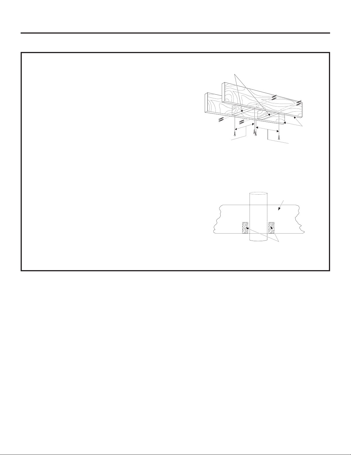
Ceiling Support Structure
• At the hood location, install cross framing between
ceiling joists as shown. (2x4 wood supports are
required to support the weight of the hood.)
Ceiling
Duct covers
Hood
ducting
centerline
µ
µ
Align with
center of
cooktop
• Arrange cross framing in the ceiling to suit the
existing structure.
<RXUFHLOLQJMRLVWVZLOOEHOLNHRQHRIWKHIROORZLQJ
examples.
µ
Cooktop
Countertop
Side view
EXAMPLE A
16” Joist
spacing
Install cross-framing symmetrically
RYHUGXFWFRRNWRSFHQWHUOLQH
µ
µ
Top view – ceiling joists parallel to front of hood
8” Duct
Front
of
hood
2x4 Cross framing
wood supports
Align duct to
center of cooktop
Cooktop
outline
49-80550-4
13

Installation Preparation
PREPARE TO INSTALL THE HOOD
CONSTRUCT CEILING SUPPORT (Continued)
EXAMPLE B
Install cross-framing
V\PPHWULFDOO\RYHUGXFW
16” Joist
spacing
µ
Top view – ceiling joists run perpendicular to front of hood
cooktop centerline
µ
8” Duct
Front
hood
of
Align duct
to center
of cooktop
Cooktop
outline
2x4 Cross
framing wood
supports
EXAMPLE C
Install cross-framing
V\PPHWULFDOO\RYHUGXFWFRRNWRS
centerline
µ
16” Joist
spacing
Top view – ceiling joists at angle to front of hood
Front
of hood
µ
8” Duct
2x4 Cross
framing wood
supports
Align duct
to center
of cooktop
Cooktop
outline
14
49-80550-4
Installation Preparation
PREPARE TO INSTALL THE HOOD
CONSTRUCT CEILING SUPPORT (Continued)
• Secure each 2 x 4 block with at least four (4), #10
wood screws, 3” long (not supplied). Use 8 wood
screws total for the two supports.
• The cross framing must be accurately aligned
to assure correct positioning of the hood.
• The cross framing must be level in all directions.
Check with a spirit level and adjust if necessary.
IMPORTANT: The ceiling structure must be capable
of supporting the weight of the hood (approximately
200 pounds) and any inadvertent user contact loads.
The hood support frame will be supported by the
2 x 4 cross framing.
Ductwork for Installations Vented to the Outdoors
• Use the shortest and straightest duct route for
satisfactory performance.
• This vent hood must use 8” round rigid duct.
• Install the house ductwork to run horizontally
between ceiling joists or straight up through
the roof.
Finish the Ceiling
• Finish the ceiling surface. Be sure to mark location
of the ceiling joists and cross framing. Check to be
VXUHWKHFHLOLQJLVOHYHOXVHVKLPVLIQHFHVVDU\
2 x 4 min.
Cross framing
µ
Vent straight up
through the ceiling
Ceiling
joist
µ
Ceiling joist
8”
Duct
2 x 4
49-80550-4
15
Installation Preparation
,167$//$7,21³9(17('727+(2876,'(
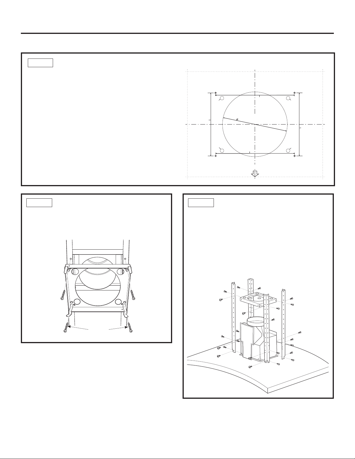
STEP 1 MOUNT TEMPLATE
• Align the template with the marks on the ceiling
and tape in place.
– Be sure the template is oriented correctly
with the front of the hood.
• Use a plumb bob to be sure the mounting holes
will provide parallel alignment with the countertop
below.
• Determine wire access hole location.
• Center punch all screw and determined wire hole
locations.
'ULOOSLORWKROHVLQWKHVFUHZORFDWLRQV8VHDµ
ELWDQGGULOODSSUR[LPDWHO\µGHHS
'ULOORQHµKROHIRUZLUHV
&XWWKHµGXFWRSHQLQJWKURXJKWKHFHLOLQJ
8-1/4"To
Centerline of
PilotHoles
Cutone 1/2" Dia.
WireAccess Hole
asNeeded
Cutone 1/2" Dia.
WireAccess Hole
asNeeded
10-5/16"To
Centerline of
PilotHoles
36" HOOD
8-
1
/2"
TEMPLATE
10-5/16"To
Centerline of
PilotHoles
FRONT OF HOOD
Drill3/16" Pilot Holes
Approx.1-1/2" Deep
Cutone 1/2" Dia.
WireAccess Hole
asNeeded
Cutone 1/2" Dia.
WireAccess Hole
asNeeded
4Places
8-1/4"To
Centerline of
PilotHoles
31-14772
Printedin Mexico
12-08JR
STEP 2 INSTALL CEILING SUPPORT
• Using 4 wood screws provided, attach the ceiling
support to the ceiling over duct opening hole
using pilot holes drilled in step 1.
Front
Screws
STEP 3 INSTALL LOWER VERTICAL
AND HORIZONTAL SUPPORTS
TO HOOD ASSEMBLY
• Using screws provided, attach the 4 lower
vertical supports to the hood assembly with 4
screws per support.
• Using screws provided, install the horizontal
support in the top outer holes of the vertical
supports.
16
49-80550-4
Installation Preparation
,167$//$7,21³9(17('727+(2876,'(
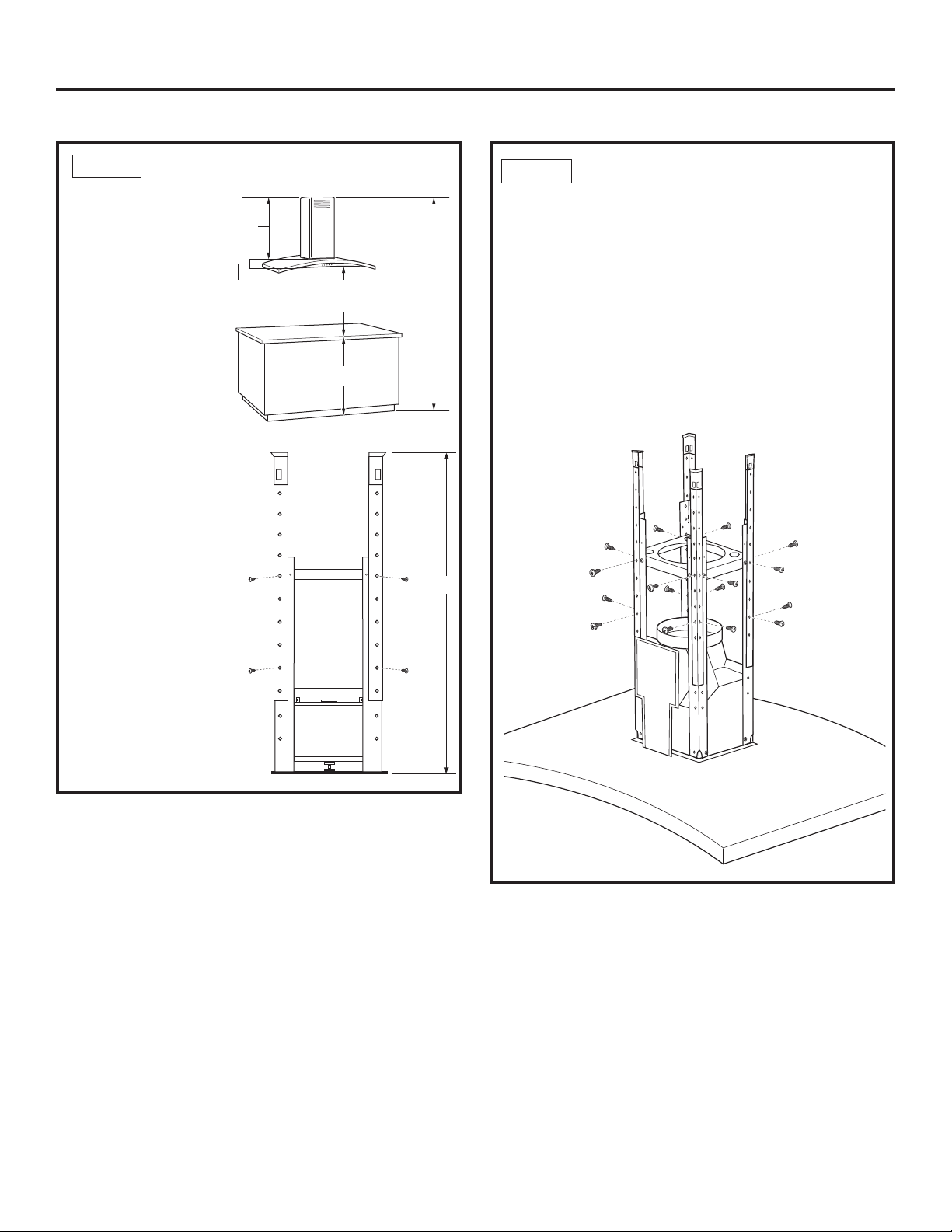
STEP 4 DETERMINE FRAME HEIGHT
•Measure exact
ceiling height.
• Use this formula
to determine
your frame
KHLJKW
A-(B+C+D) =
Frame height E
where A is the
ceiling height, B
is the countertop
height, C is the
installation
height, D is the
height of the hood
measured from the
straight bottom
portion to the top at
the center.
E
Frame
height
D
µ
A
24” Min.
36” Recommended Max.
C
36” Typical
B
Ceiling
height
E
STEP 5 INSTALL UPPER VERTICAL
SUPPORTS TO HOOD ASSEMBLY
• Determine how much of the upper vertical
supports will need to be above the lower supports
to accomplish the frame height determined in
step 4 for this installation.
• Using screws provided, attach the 4 upper vertical
supports to the lower vertical supports at the
position determined for frame height. The upper
vertical supports are mounted to the outside
of the lower supports.
49-80550-4
17

Installation Preparation
,167$//$7,21³9(17('727+(2876,'(
STEP 6 CUT DUCT TO LENGTH
FOR VENTED INSTALLATION
• Measure from the hood exhaust opening to
the top of the supports as shown in the figure.
• Subtract any length of duct that is protruding
through the ceiling.
• Cut the 8” duct to the appropriate length. Attach
to ceiling duct using aluminized tape and screws.
Length of duct
needed minus the
length protruding
through the
ceiling.
STEP 7 INSTALL HOOD ASSEMBLY
TO CEILING SUPPORT
WARNING
to lift and position the hood onto the support.
• Lift the hood assembly up to the ceiling support.
Carefully fit the newly assembled duct over
exhaust opening on the hood assembly. The clips
on the ceiling support will snap into the large
openings on the upper vertical supports.
• Using the screws provided, attach the upper
vertical supports to the ceiling support, 4 screws
per side, for a total of 16 screws.
• Seal duct with aluminized duct tape.
Two people are required
Clips
Ceiling
support
Seal with
aluminized
duct tape
18
49-80550-4
 Loading...