How it Works
Log In / Sign Up
Buy Points
How it Works
FAQ
Contact Us
Questions and Suggestions
Users
GE
Loading...
P
PTS25LHSCC
PTS25LHSCRBB
PTS25LHSCRCC
PTS25LHSCRWW
PTS25LHSWW
2
PTS25SBMARBS
PTS25SBMBRBS
PTS25SHPARBS
PTS25SHRARBS
PTS25SHRBRBS
PTS25SHRCRBS
PTS25SHS
PTS25SHSARSS
PTS25SHSCRSS
PTS25SHSSS
2
PTS7000
PTS7000BN
PTS7000BNTS
3
PTS7000FN
PTS7000FNDS
PTS7000SN
PTS7000SNSS
PTS700L
PTS700LSN
PTS700R
PTS700RSN
PTS9000
PTS9000BN
PTS9000BNTS
PTS9000SN
PTS9000SNSS
PTS9200
PTS9200SNSS
3
PTW600
PTW605
PTW9000
PTW9000SNSS
2
PTWN6050M
PTWN6050M0WT
2
PTWN6250M
PTWN6250M0WT
2
PTWN8050M
PTWN8050M0WW
PTWN8055M
PTWN8055M0MS
PTZ 100
PTZ 12X
PTZ 140
PTZ 70
Pump Motors
5
PV970
PV970N1SS
PV970N2SS
PV970NSS
PV976
PV976N
PV976N1SS
PV976N2SS
PV976NSS
2
PV977
PV977N1SS
PV977N2SS
PV977NSS
PVB37
PVB94DT
PVB94DT1BB
2
PVB94DT2BB
2
PVB94DT3BB
2
PVB94DT4BB
2
PVB94DT5BB
2
PVB94DTBB
PVB94SN
PVB94SNSS
PVB94ST1SS
2
PVB94ST2SS
2
PVB94ST3SS
2
PVB94ST4SS
2
PVB94ST5SS
2
PVB94STSS
5
PVB98DT
PVB98DT1BB
2
PVB98DT2BB
2
PVB98DT3BB
2
PVB98DT4BB
2
PVB98DT5BB
2
PVB98DTBB
3
PVB98SN
PVB98SNSS
PVB98ST
PVB98ST1SS
2
PVB98ST2SS
2
PVB98ST3SS
2
PVB98ST4SS
2
PVB98ST5SS
2
PVB98STSS
4
PVD
PVD28BYNBFS
PVD28BYNFS
3
PVIG940
2
PVM1790
Loading...
Loading...
Nothing found
PV970
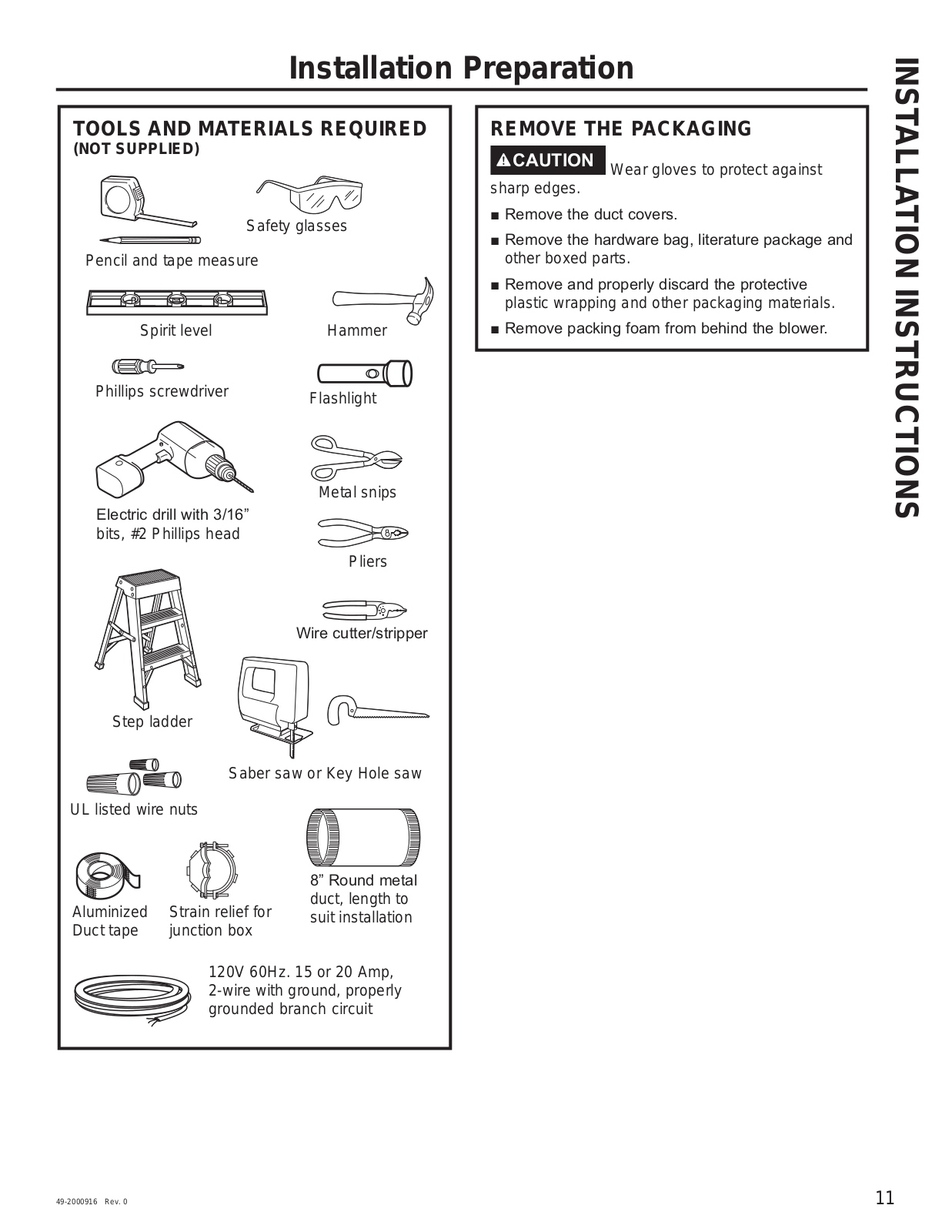
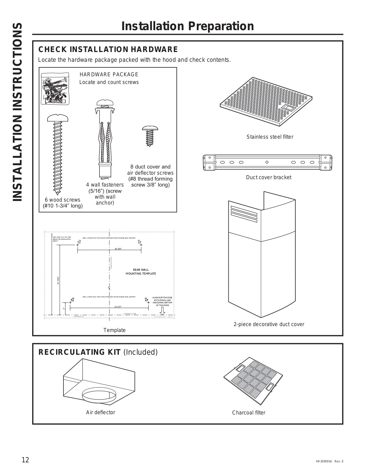
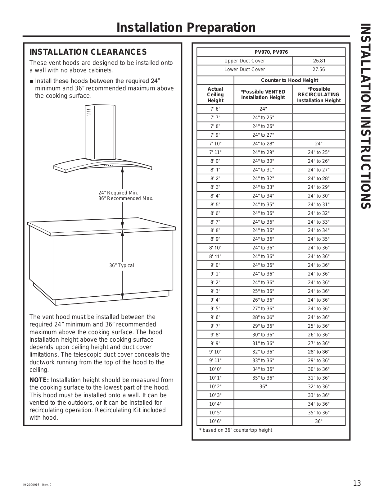
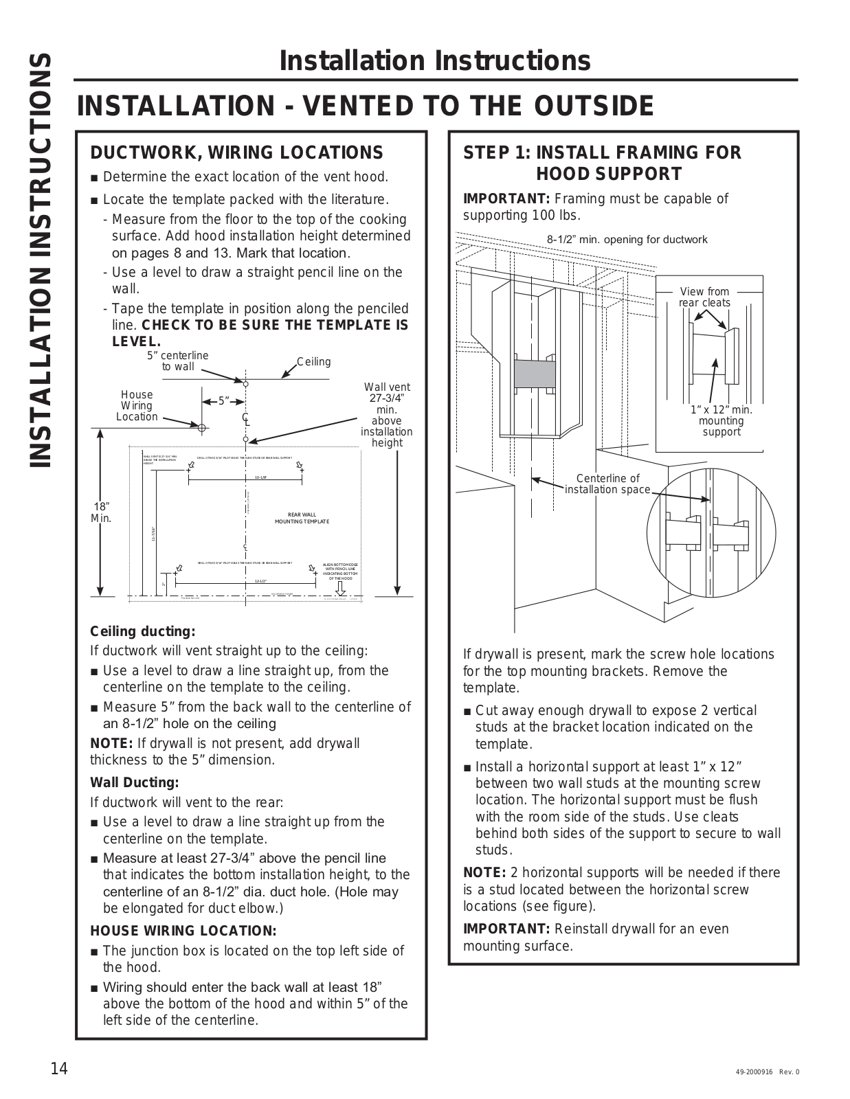
Owner’s Manual & Installation Instructions
52 pgs
691.66 Kb
0
Table of contents
Loading...
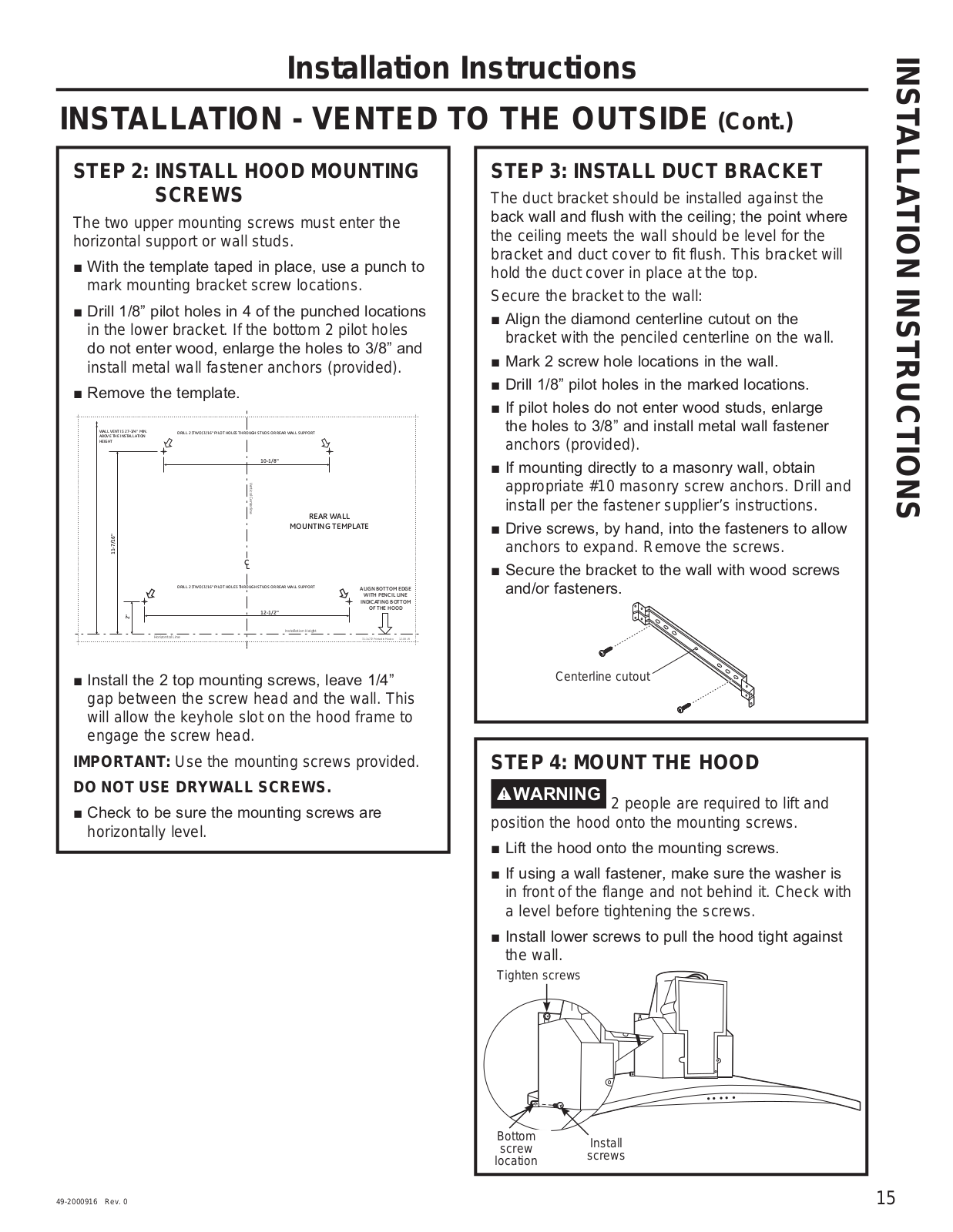
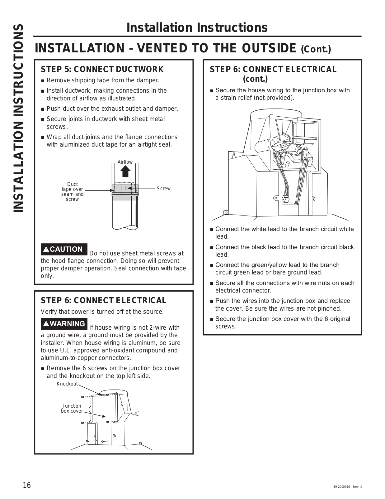
GE PV970, PV976 Owner’s Manual & Installation Instructions
...
GE Owner’s Manual & Installation Instructions
Download
Specifications and Main Features
Frequently Asked Questions
User Manual
Download
Loading...
+
36
hidden pages
Unhide
You need points to download manuals.
1 point = 1 manual.
You can buy points or you can get point for every manual you upload.
Buy points
Upload your manuals