

GE PTWN8055MMS, PTWN8050MWW User Manual

GWS 05/06/2011
Copyright 2010
GE Profile 5.2 IEC* cu. ft. Stainless Steel
Capacity Washer
Models:
PTWN8055MMS (Metallic Silver)
PTWN8050MWW (White)
2011 Energy Star® qualified
Service Guide
Pub# 31-9211

Copyright 2011
2
IMPORTANT SAFETY NOTICE
The information in this presentation is intended for use by individuals
possessing adequate backgrounds of electrical, electronic, & mechanical
experience. Any attempt to repair a major appliance may result in
personal injury & property damage. The manufacturer or seller cannot be
responsible for the interpretation of this information, nor can it assume
any liability in connection with its use.
WARNING
To avoid personal injury, disconnect power before servicing this product.
If electrical power is required for diagnosis or test purposes, disconnect
the power immediately after performing the necessary checks.
RECONNECT ALL GROUNDING DEVICES
If grounding wires, screws, straps, clips, nuts, or washers used to complete
a path to ground are removed for service, they must be returned to their
original position & properly fastened.
Copyright 2011
3
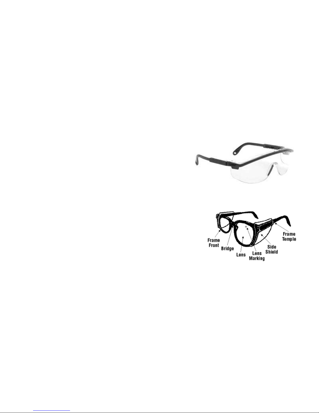
GE Factory Service Employees are required to use safety glasses with side
shields, safety gloves & steel toe shoes for all repairs.
Dyneema® Cut
Resistant Glove
Safety Glasses
must be
compliant with
ANSI Z87.1-2003
Prescription Safety Glasses
Plano Safety Glasses
Steel Toe Shoes
VR Gloves – provide shock protection
Copyright 2011
4
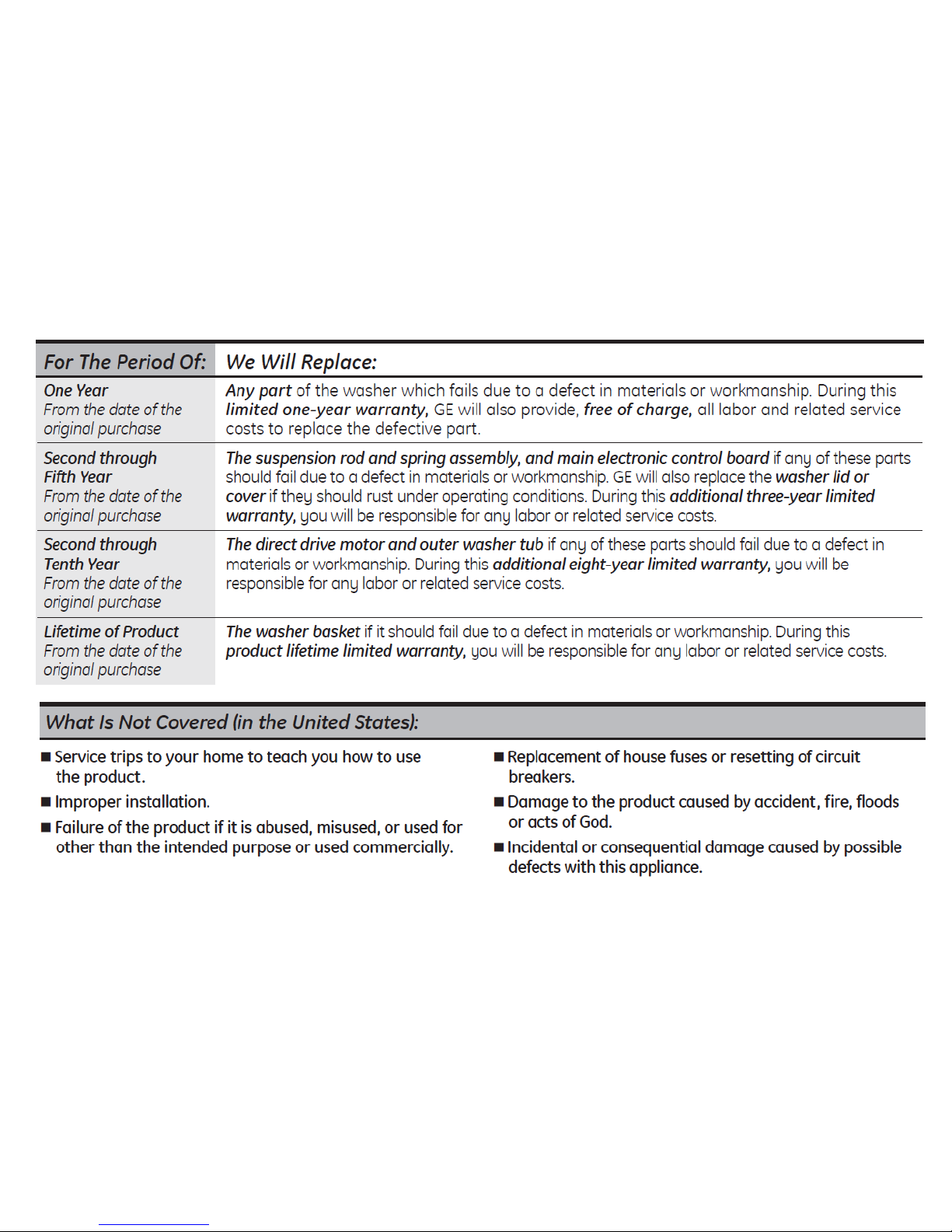
Warranty

Copyright 2011
5
Nomenclature

Copyright 2011
6
Model / Serial Plate
Model / Serial plate is located on the rear of the
backsplash just above the water inlet connections.
Copyright 2011
7
Mini-Manual
Mini-Manual is packaged inside a plastic bag and is located
inside the backsplash between the pressure switch and the
water valve assembly.

Copyright 2011
8
Wash Cycles
“Tidal Wave” or “Alpha Wash”
Basket spins at 230 RPM clockwise then counter-clockwise.
“Centrifusion Wash”
Basket spins slowly clockwise then counter-clockwise.
“Infusor Wash”
Tub remains stationary. Infusor turn clockwise then counter-clockwise.

Copyright 2011
9
Dispenser Drawer
• For powder detergent, remove the tray & insert.
• To remove drawer for cleaning, pull out to stop, lift front upwards
and pull completely out of machine.

Copyright 2011
10
HE Detergent
Use & Care recommends the use of HE detergent only.

Copyright 2011
11
Cycle Cancellation
NOTE (1):
If the customer cancels a cycle by pressing the power pad, after four
minutes the pump will turn on and pump the water out of the tub. The
control does not illuminate or does the tub spin, just the pump is
energized till the tub is empty.
Also doesn’t matter if the lid is up or down.

Copyright 2011
12
Cycle Cancellation
NOTE (2):
If the customer pauses a cycle for an extended amount of time, after two
hours have elapsed, the machine will pump out the water in the tub and
shut off.
Also doesn’t matter if the lid is up or down.

Copyright 2011
13
My Cycle
NOTE (2):
When programming the “My Cycle” feature, the customer can not only
program any cycle but can also add any of the cycle additions, on the
right of the display, to the cycle functions. These would include Fabric
Softener, Delay Start, Extra Rise or Soak.

Copyright 2011
14
Jet Spray
“Jet Spray” is used during the rinse cycles in order to use less
water during rinse.
It sprays water over the clothes (spray rinse) as the basket rotates.
Jet Spray is the default rinse type unless either FABRIC
SOFTENER or EXTRA RINSE cycle additions are selected.

Copyright 2011
15
Control Panel
When the fabric softener pad is selected, the machine will provide a
deep rinse instead of the spray rinse.

Copyright 2011
16
Control Panel Components
• To access the control components, first begin by removing five
Phillips screws securing backsplash rear panel.
• Remove rear panel from backsplash assembly.

Copyright 2011
17
Control Panel Components
• Protect top of washer with a towel or rag.
• Tilt front control panel towards front of machine to disengage tabs.
• Lay control panel on it’s face on top of towel.
Copyright 2011
18
Control Panel Components
Pressure Switch
Water valve assembly
Noise Filter
RF choke
Control assembly

Copyright 2011
19
Control Panel Components
To remove metal shield from control board assembly, pull outward
on side tabs.
Caution: Metal edges are sharp

Copyright 2011
20
Control Panel Components
Removing the metal cover will expose the plug connections and the
individual electronic components on the power board.

Copyright 2011
21
Control Panel Components
• To separate the control assembly from front panel, remove ten
(10) Phillips screws.
• Lift board assembly from panel.

Copyright 2011
22
Control Panel Components
Selector buttons or pads are held to the control panel with tabs and are
replaced as a complete assembly.

Copyright 2011
23
Control Panel Components
• The control assembly consists of a Power Board and a Display / Logic
Board.
• They are held together as an assembly by plastic tabs and connected
electrically by two interconnect plugs and cables.
POWER BOARD
DISPLAY / LOGIC BOARD

Copyright 2011
24
Control Panel Components
Red LED indicates that the power board is powered and “awake”.

Copyright 2011
25
Control Panel Components
To separate the two control boards, first pry back plastic tabs then
pry the two boards apart.

Copyright 2011
26
Control Panel Components
Finally, disconnect the two electrical connectors from the Power
Board.

Copyright 2011
27
Water Valve Assembly
(Rear View)
Water valve assembly is accessible after removing the control panel from
the top of the machine.

Copyright 2011
28
Water Valve Assembly
• The water valve consists of a valve body and five solenoid coils.
• It is only available as a complete assembly.
• Each solenoid controls a specific water function.

Copyright 2011
29
Water Valve Assembly
(Front View)
Bleach
Dispenser
Softener
Jet Spray
Cold
Hot
Each coil on the water valve assembly has an approximate resistance
value of 30 Ω and should read 5-6vdc across the coil when energized.

Copyright 2011
30
Water Valve Assembly
Pink colored, plastic pressure fittings are used in the water distribution
system for a tight fit and to reduce the possibility of leaks.
 Loading...