

GE PTS25SHSCRSS, PTS25LHSCRWW, PTS25LHSCRCC, PTS25LHSCRBB, PTS22SHSCRSS Owner’s Manual
...
N
ge.com
Safely Instructions
Connect Electricity ................ 3
Extension Cords .................. 2
Proper Disposal ................... 9
Safety Precautions ................. 9
Models 22,25
Operating Instructions
Additional Features ................ 9
Automatic Icemaker . ............. l0
Oonuols ...................... 4, 5
Crispers and Pans .............. 9, 10
Shelves and Bins ................ 7, 8
V_'ater Dispenser . ................ 11
V{ater Fiher . ..................... 6
Care and Cleaning .............. 11
Replacing the Light Bulbs ......... 19
In_lallation ImCrudions
Preparing to Install
the Refiig_rator .................. 13
Rexersing the Door Swing ...... 18-92
V_'amr Line Installation ......... 14-18
Troubleshooting Tips ......... 24-26
Nomml Operating Sounds ......... 93
Consumer Support
Oonsumer Support ........ Back Co_r
Perfot_nance Data Sheet ........... 97
Stare of Calitbmia Wamr
Treaunent Device Certificam ....... 98
¼'atTantv for Canadian Customers ...99
_'atTantv for U.S. Customers ....... 30
Cong_lateur sup_rieur
Rg frigg rateurs
La section fran_aise commence a la page 31
Congelador superior
Refrigeradores
La secci6n en espa#ol empieza en la pagina 63
Write the model and serial numbers here:
Model #
Serial #
Find these numbers on the gray label
on the lett side, near the top of the
refrigerator compartment.
200D8221PO01 49-60445 !1-05 Jfl
IMPORTANTSAFETYINFORMATION.
READALLINSTRUCTIONSBEFOREUSING.
WARNING!
Use this appliance only for its intended purpose as described in this Owner's Manual
SAFETYPRECAUtiONS
When using electrical appliances, basic safety precautions should be followed, including the following:
_:i:This refl_igerator must be i)roperly installed
and located in accordance with tile Installation
Instructions beiore it is used.
::_ Do not allow children to climb, stand or hang
on the shelves in the reli_igeratm: They could
damage the reli_igerator and seriously iqjure
themselves.
i_J_Do not touch tile cold sm'fi_ces in tile fl'eezer
compartment when hands are damp or wet.
Skin max stick t() these extremely cold sm'ti_ces.
i)::Do not store or use gasoline or other flammable
vapors and liquids in the vicinity of this or any
other appliance.
::_ In refligeratcn_ with automatic icemakeI_,
avoid contact with tile moving parts of tile
ejector mechanism, or with the heating
element located oil the bottom at the icemaker
Do not place finge_ or hands on the aUtOlnatic
icemaking mechanism while the reii_igerator
is plugged in.
i):: Kee I) fingeI_ out of tile "pinch point" areas;
clearances between the (lom_ and between
the doois and cabinet are necessarily small.
Be careflfl closing doois when children are
in the area.
::_ UnI)lug tile refrigerator betin'e cleaning and
making repaiI_.
NOTE: Westronglyrecommendthat anyservicingbe
performedby aquafified individual
i)::Setting tile controls to tile 0(Off)position does
not remove power m tile light circuit. On some
models, only the refl-igerator control has a
0 (off) setting.
::_ Do not reii'eeze frozen foods which have
thawed completely:
DANGER!RISKOFCHILDENTRAPMENT
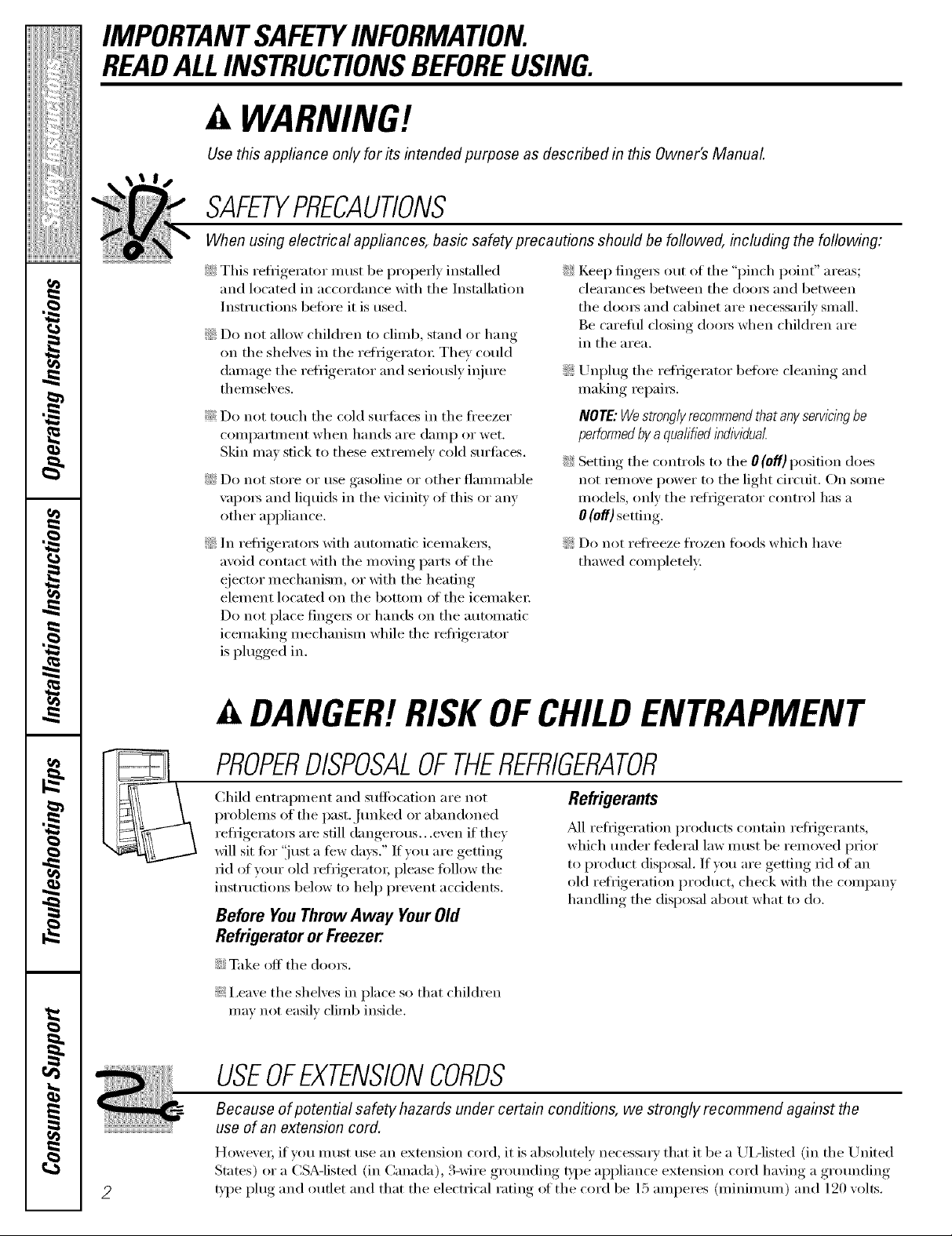
PROPERDISPOSALOFTHEREFRIGERATOR
Child entrai)inent and suffocation are not
problems of the past..J/mked or abandoned
refl'igerato_ are still dangerous...even if they
will sit tin" "just a few days." If you are getting
rid of yam" old refrigerato_; please tallow tile
instructions below to hel I) prevent accidents.
Before YouThrowAway YourOld
RefrigeratororFreezer:
::Ji::Take off tile clom_.
!i?:I,eaxe tile shelxes in place so that children
mm not easilx climb inside.
Refrigerants
M1 refl-igeration products contain reli_igerants,
which under fi_deral law nlust be removed prior
to product disposal. If you are getting Jd of an
old reli_igeration product, check with tile company
handling tile disposal about what to do.
USEOFEXTENSIONCORDS
Because of potential safety hazards under certain conditions, we strongly recommend against the
use of an extension cord.
HoweveI; if you IllllSt rise an extension cord, it is absohltely necessai'y that it be a UiAisted (ill tile United
Stares) or a CSA-listed (in Canada), 3-wire grotmding b'pe appliance extension cord having a grotmding
D'pe i)lug and outlet and that tile electrical rating _ff tile cord be 15 amperes (minimmn) and 120 volts.
WARNING!
HOWTOCONNECTELECTRICITY
Donot, under any circumstances, cut or remove the third (ground) prong from the power cord. For
personal safezg,this appfiance must be properly grounded.
ge.com
The power cord of this appliance is equipped
with a &prong (grounding) plug which mates
with a standard 3-prong (gromMing) wall outlet
to minimize the possibili_, of electric shock hazard
fl'om this appliance.
Have the wall out.let and circuit checked bv
a qualified electrician to make sm'e the out.let
is properly grotmded.
If the outlet is a standard 2-pr(mg outlet,
it is yore" personal responsibiliQ and obligation
to have it replaced with a properly gr(mnded
S-prong wall outlet.
The refl-igerator should alwa D be plugged into
its own individual electrical outlet which has
a w)ltage rating that matches the rating plate.
This provides the best pe_l'bmmnce and also
I)rexents oxerloading, house wiring, circuits which
could cause a fire hazard fl'om oxerheated wires.
Never m_plug yore" refl-igerator by pulling on the
power cord. Mways grip plug firefly and pull
straight out fl'om the outlet.
Repair or replace immediately all power cords
that have become fl'aved or otherwise damaged.
Do not rise a cord that sho_:s cracks or abI'asion
damage along its length or at either end.
When moving the refligerator away fl'om the
wall, be careflfl not to roll over or damage the
power cord,
READANDFOLLOWTHISSAFETYINFORMATIONCAREFULLY.
SAVETHESEINSTRUCTIONS
3
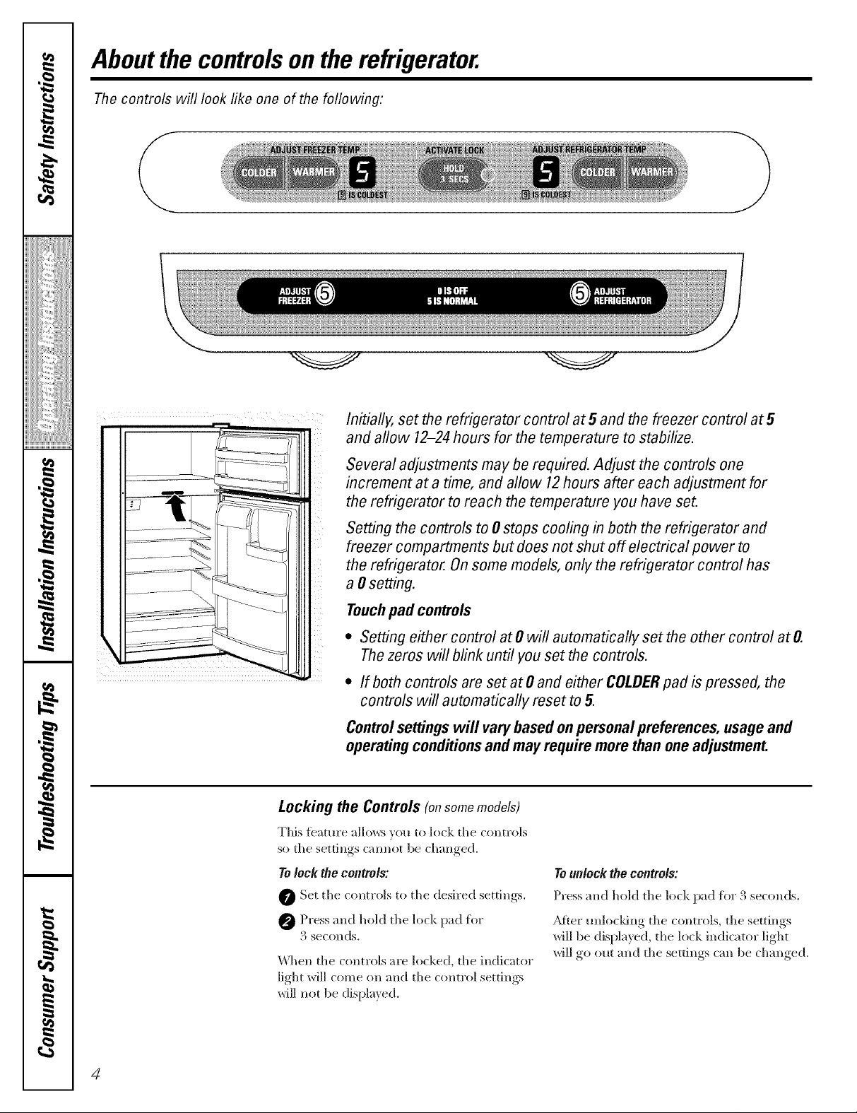
Aboutthe controlsonthe refrigerator.
Thecontrols will look like one of the following:
Initially, set the refrigerator control at5 and the freezer control at5
and allow 12-24hours for the temperature to stabilize.
Several adjustments may be required. Adjust the controls one
increment at a time, and allow 12hours after each adjustment for
the refrigerator to reach the temperature you have set.
Setting the controls to #stops cooling in both the refrigerator and
freezer compartments but does not shut off electrical power to
the refrigerator. Onsome models, only the refrigerator control has
a 0setting.
Touchpad controls
* SettingeithercontrolatOwillautomaticallysettheothercontrolatO.
Thezeros will blink until you set the controls.
* If both controls are set at 0 and either COLDERpad ispressed, the
controls will automatically reset to 5.
Controlsettingswill vary basedonpersonalpreferences, usageand
operatingconditionsandmayrequire more than oneadjustment.
Locking the Controls (onsomemodem
This te_mn'e allo_:_ )'(_u to lock tile controls
so tile settings cam_ot be changed.
Tolock the controls:
O Set tile controls to tile desired settings.
0 Press and hold tile lock pad tiw
3 seconds.
When tile controls are locked, tile indicator
light will come on and tile control settings
will not be displ_lyed.
To unlock the controls:
Press and hold tile lock pad %r 3 seconds.
Mter mflocldng tile controls, tile settings
will be displayed, tile lock indicator light
will go out and tile settings can be changed.
4
Aboutthe temperaturecontrols, gecom
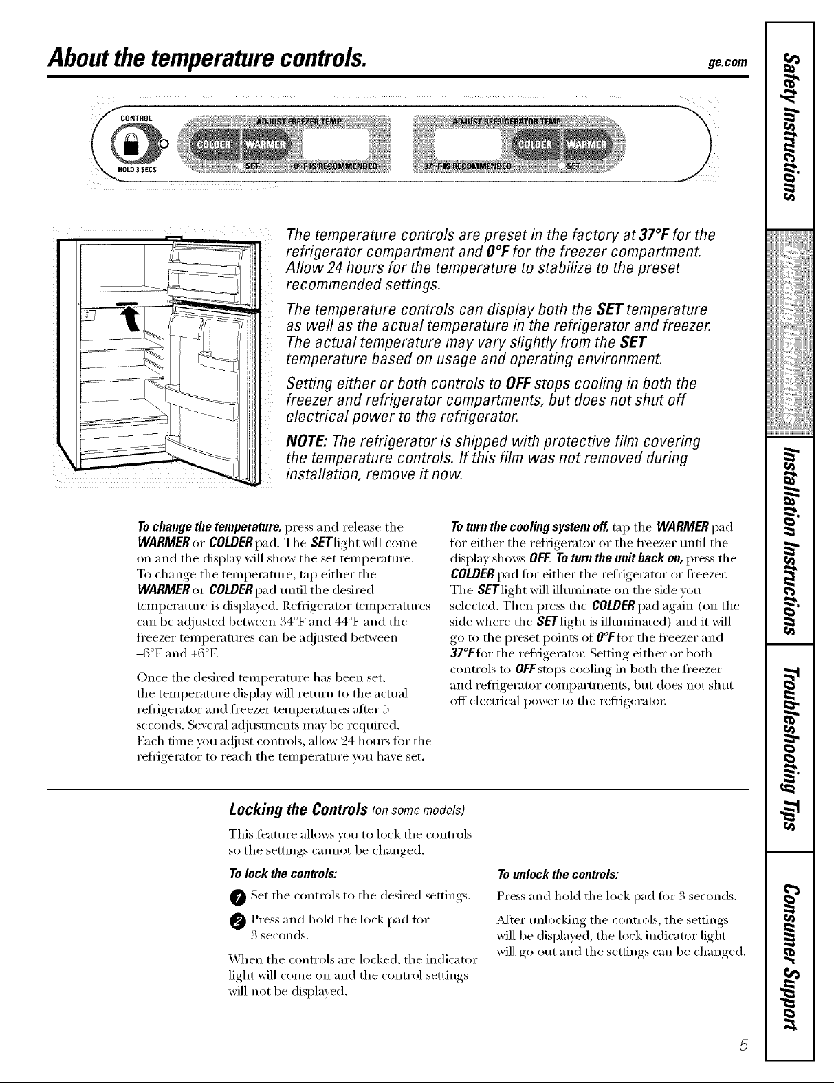
HOLO 3 SECS
The temperature controls are preset in the factory at 37°F for the
refrigerator compartment and O°Ffor the freezer compartment.
Allow24 hours for the temperature to stabilize to the preset
recommended settings.
The temperature controls can display both the SET temperature
as well as the actual temperature in the refrigerator and freezer.
The actual temperature may vary slightly from the SET
temperature based on usage and operating environment.
Setting either or both controls to OFFstops cooling in both the
freezer and refrigerator compartments, but does not shut off
electrical power to the refrigerator.
NOTE: The refrigerator is shipped with protective film covering
the temperature controls. If this film was not removed during
installation, remove it now.
To change the temperature, press and release the
WARMER or COLDERpad. Tile SETlight will come
on and tile display will show tile set temi)eramre.
To change the temperature, tap either the
WARMER or COLDER pad until tile desired
telnl)erature is displayed. ReflJgerator telnl)eratures
can be a(!justed between 34°F and 44°F and tile
fl'eezer teinperatures can be ac!justed between
-()°F and +6°E
Once the desired temperature has been set,
tile temperature display will return to tile actual
refi_gerator and fl'eezer teilll)erattlres after 5
seconds. Several a(!justments may be required.
Each time you a(!just controls, allow 24 hom_ fin" the
refl_igerator to reach the temperature you have set.
Locking the Controls (on some models)
This feature allo_vs w_u to lock tile controls
so the settings cannot be changed.
To lock the controls:
@ Set tile controls to tile desired settings.
Press and hold the lock pad fin.
3 seconds.
When the controls are locked, the indicator
light will come on and the control settings
will not be displayed.
To turn the cooling system off, tap the WARMER pad
fin" either tile refi_gerator or tile fl'eezer tmtil tile
display sho_:s OFF. To turn the unit back on, press tile
COLDER pad fin" either tile refrigerator or fl'eezex:
The SETlight will ilhmfinate on the side w)u
selected, Then press the COLDER pad again (on the
side where the SETlight is ilhmfinated) and it will
go to the preset points of O°Ffi)r the fl'eezer and
37°Ffl)r tile refl_igeratox: Setting either or both
controls to OFFstops cooling in both the fi'eezer
and refl_igerator compartments, but does not shut
off electrical power to tile reli_igerator
Tounlock the controls:
Press and hold tile lock pad fin" 3 seconds.
_Mter Âmloc!dng tile controls, tile settings
will be displayed, the lock indicator light
will go out and the settings can be changed.
Aboutthe water filter.(onsomemodels)
Water Filter Cartridge
The water filter cartridge is located inside
the cartridge holder in the back upper right
corner of the reflJgerator c(nni_artment.
NOTE:Some models ship with the filter
bypass plug in place of tile filter cartridge.
The filter byl)ass I_lug needs U) be removed
betore the filter cartridge is installed. Keep
tile filter byl)ass I_lug fiw flmu'e use.
When to Replace the Filter
The filter cartridge should be replaced
every six monthsor earlier if the flow ot
water to tile icemaker and dispenser
decreases.
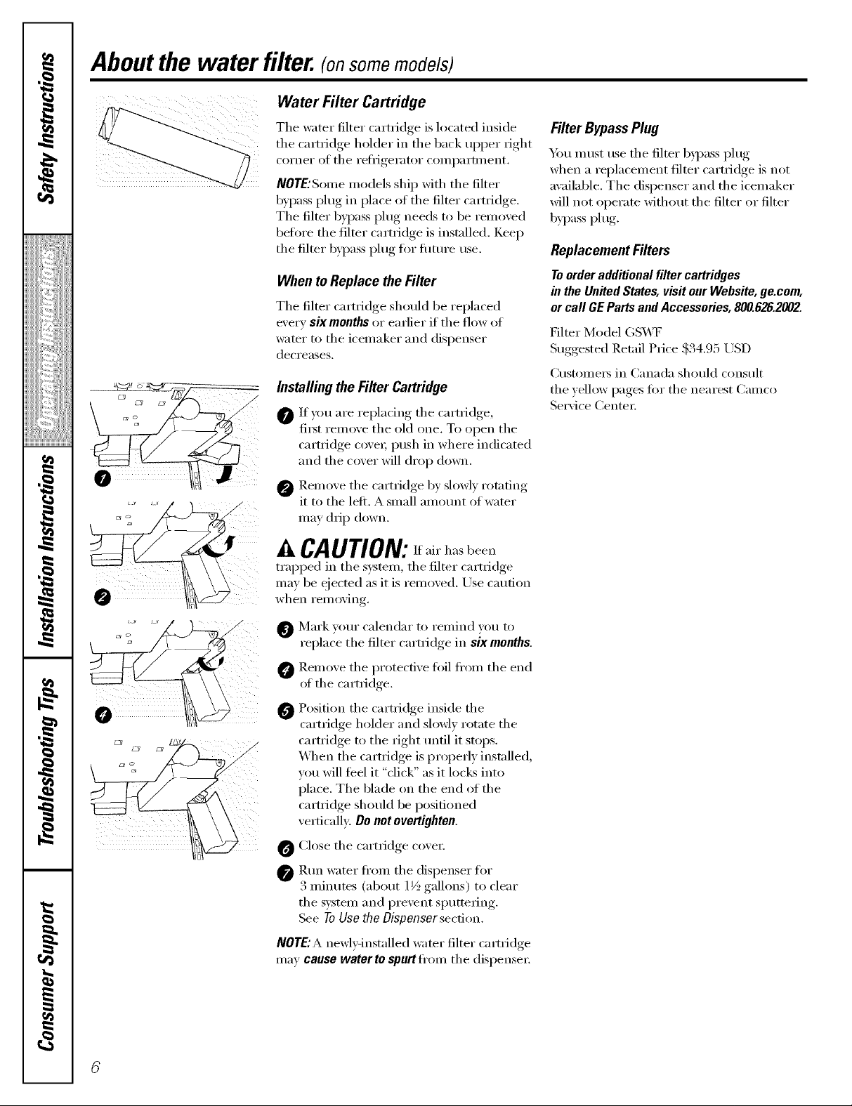
Installing the Filter Cartridge
0 If you are replacing tile cartridg-e,
fi_t remoxe tile old one. To open tile
cartridge cove_; push in where indicated
and tile cover will drop down.
@ Remoxe tile cartridge b) slowl) rotating
it to tile left. A small amount of water
may drip down.
Filter Bypass Plug
Y)u must use tile filter byl)ass plug
when a replacement filter cartridge is not
awfilable. The dispenser and the icemaker
will not operate without tile filter or filter
bypass plug.
Replacement Filters
Toorderadditionalfiltercartridges
in theUnitedStates,visitourWebsite,go.corn,
or call GEPartsandAccessories,800.626.2002.
Filter Model GS_.VF
Suggested Retail Price $34.95 USD
()lStOlllers in Canada should constllt
the yellow pages ti)r tile nearest Camco
Service Center:
'_ CAUTION_ Ifair has been
trapped in the system, the filter cartridge
may be eiected as it is remoxed. Use caution
when I'eIllOx, in r
Mark yore" calendar to remind you to
replace tile filter cartridge in six months.
@ Remove tile protective fi)il fl'om tile end
of tile cartridge.
Position the cartridge inside the
cartridge holder and slowl) rotate tile
cartridge to tile right tmfil it stops.
When tile camidge is property installed,
vou will feel it "click" as it locks into
place. The blade on the end of the
cartlidge should be positioned
xertically: Do not ovortighton.
O Close tile cartridge cove_;
@ Run water fl'om tile dispenser fl)r
3 minutes (about 1½ gallons) to clear
tile system and prevent sputtering.
See 7"0{]so the l)isponsor section.
NOTE:A newEqnstalled water filter cartridge
may ca#so water to spurt tiom tile dispense_:
Abouttheshelvesandbins. gecem
Not all features are on all models.
Rearranging the Shelves
Shel',es in the refl-igerator,..... and fl'eezer coml)artments are a(!iustnble.
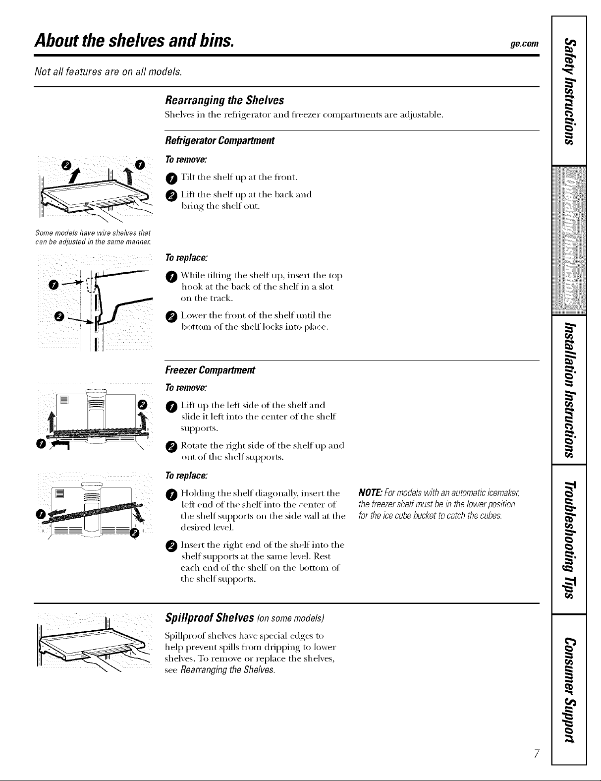
Refrigerator Compartment
Toremove:
0 Tilt the shelf up at the fl'(mt.
I,ifi the shelf up at the back and
bring the shelf out.
Some models have wire shelves that
can be adjusted in the same mamTer.
To replace:
0 _ hile tilting the shelf up, insert the top
hook at the back of the shelf in a slot
i __ iil i
ii
on the track.
0 I,ower the fl'ont of the shelf tmtil the
bottom of the shelf locks into place.
Freezer Compartment
Toremove:
I,ifl up the leti side of the shelf and
slide it leti into the center of the shelf
supports.
0 Rotate the fight side of the shelf up and
out of the shelf supports.
Te replace:
Holding the shelf diagonally, insert the
left end of the shelf into the center of
the shelf sui)ports on the side wall at the
desired level.
Insert the right end of the shelf into the
0
shelf supports at the same level. Rest
each end of the shelf" on the bottom oI
the shelf supports.
Spillproof Shelves (onsomemodels)
Spillproof shelves ha_e sl)e(ial edges to
hel I) prexent spills fl'om dfipl)ing to lower
shel',es. To remo_,e or replace the shel',es,
see Rearranging the Shelves.
NOTE."Formodelswith an automaticicemaker,
the freezershelf must be in thelower position
forthe ice cube buckettocatch the cubes.
Abouttheshelvesandbins.
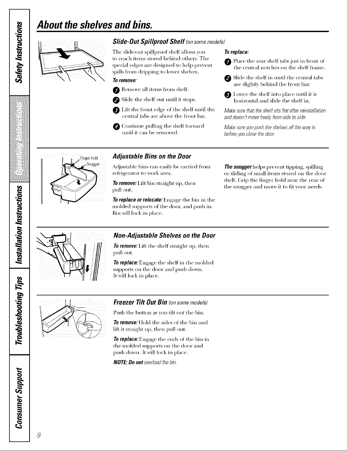
Sfide-Out Spil/proof Shelf (onsomemodels)
The slide-out spillproof shelf allows you
to reach items stored behind othe_. The
spedal edges are designed to help prevent
spills from dripping to lower shelves.
Toremove:
0 Remove all items ti'om shell
Slide the shelf out tmfil it stops.
I,iti the fl'ont edge of the shelf tmtil the
central tabs are above the fl'ont bin:
0 Continue pulling the shelf torward
tmtil it can be removed.
To replace:
Place the rear shelf tabs just in ti'ont ot
the central notches on the shelf fi'ame,
Slide the shelf in tmfil the central tabs
are slightly behind the front bin:
I,ower the shelf" into place tmtil it is
horizontal and slide the shelf in.
Make sure that the she/f sits fiat after relbstaiiation
anddoesn't movefreeiy fromside toside.
Make sure youpushthe shelvesa// the way in
before youclose the door
,Fingerhold
,.Snugger
Adjustable Bins on the Door
A(!justable bins can easily be carried ti'om
reflJgerator to work area.
Toremove:i,ifi bin straight up, then
pull out.
TOreplace or relocate: Engage the bin in the
molded supports of the (h)o_; and push in.
Bin will lock in place.
Non-Adjustable Shelves on the Door
Toremove: Lift the shelt straight up, then
pull out.
Toreplace:Engage the shelf in the rooMed
supports on the door and push down.
It will lock in place.
Freezer Tilt Out Bin (onsomemodels)
Push the button as you tilt out the bin.
Toremove: Hold the sides of the bin and
lift it straight up, then pull out.
Toreplace:Engage the ends ot the bin in
the molded supports on the door and
push down, ]t will lock in place,
NOTE."Do not overloadthe bin.
The snuggerhelps prevent tipping, spilling
or sliding of small items stored on the (loot"
shell (h_ii) the finger hold near the rear of
the snugger and move it to fit w)ur needs.
Abouttheadditional features, gecom
Not all features are on all models.
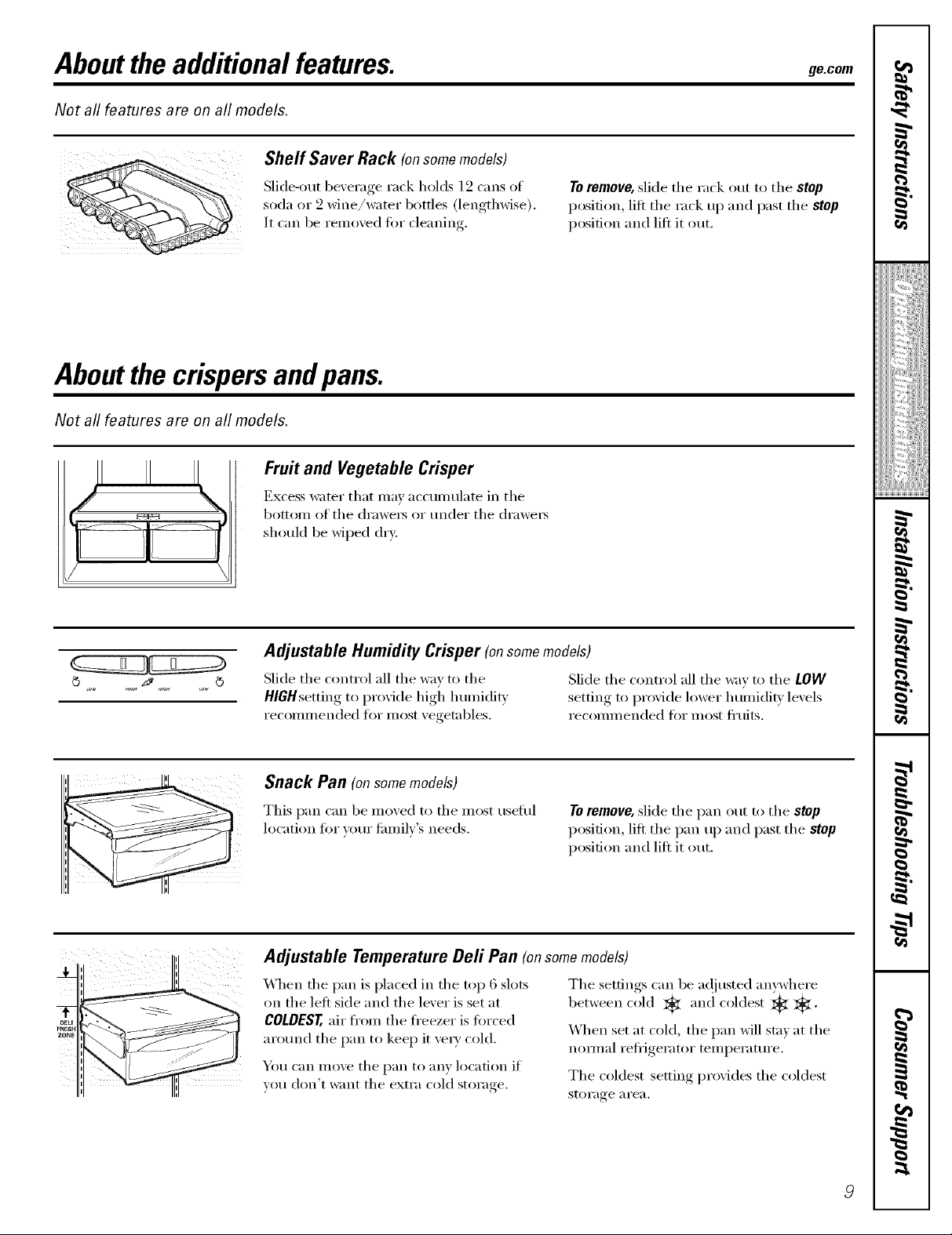
Slide-out beverage rack holds 12 cans of
soda ()r _2_ne/water" bottles (lengthwise).
It can be removed fin" cleanim,
Shelf Saver Rack (onsomemodels)
Aboutthe crispersandpans.
Not all features are on all models.
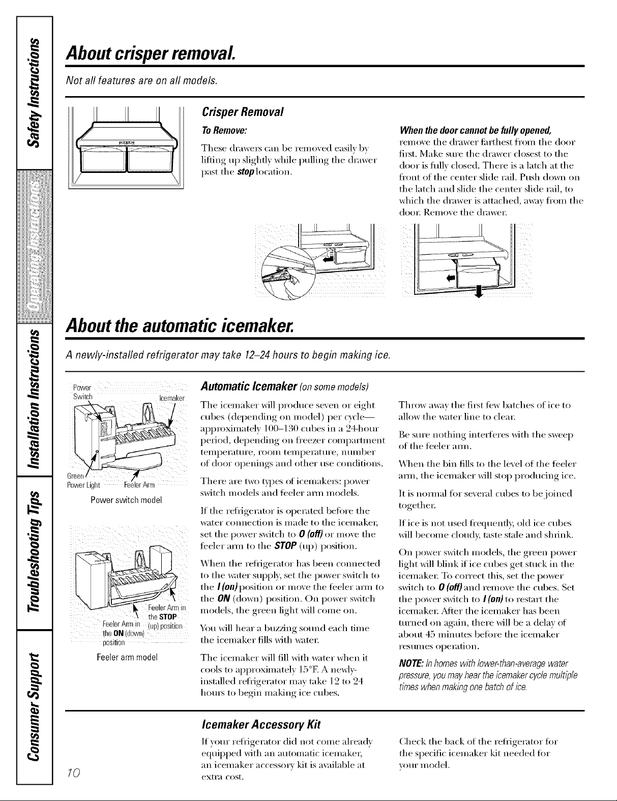
Fruit and Vegetable Crisper
Excess water that max' accumtflate in the
bottom of the (h'awe_ or trader the (h'awe_
should be wiped dry.
Toremove, slide the rack out to the stop
position, lift the rack up and past the stop
position and lift it out.
I
_!!iiii.._i_iiiii_i:il
ii_iiiii_iiii}ii;i
iii!iiiiii_i_iiiii¸
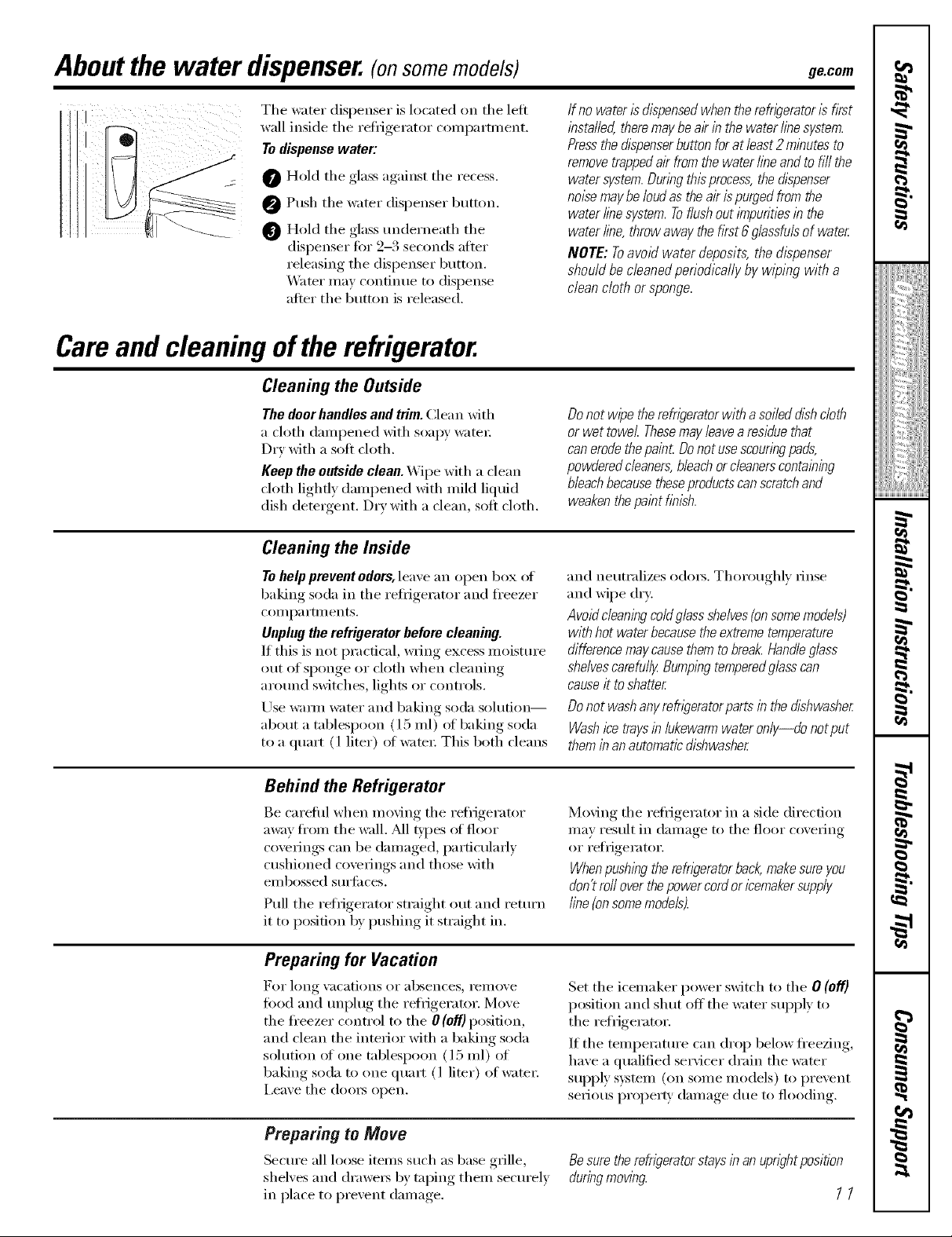
Adjustable Humidity Crisper (onsomemodels)
Slide the control all the way to the Slide the control all the way to the LOW
HIGH setting to provide high lmmidit_ .settino_ to prmide lower h umidit)levels
recommended for most ;egetnbles. recommended for most fl'uits.
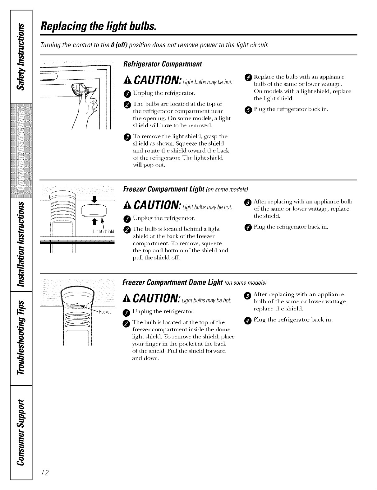
Snack Pan (onsomemodels)
This pan can be mo;ed to the most tlseflll
location fi)r _om" fhmiE's needs.
Toremove, slide the pan out to the stop
position, lift the pan uI) and past the stop
position and lift it out.
Adjustable Temperature Deft Pan (onsomemodels)
When the pan is placed in the top 6 slots
on the left side and the lever is set at
COLDEST,air fl'om the ti'eezer is fi)rced
arotmd the pan to kee I) it ve_' cold.
You can move the pan to any location if
you don't want the extra cold storage.
The settings can be ac!justed anywhere
between cold , and coldest
When set at cold, the pan will stay at the
normal refl_igerator teml)erature.
The coldest setting provides the coldest
storage _1i'e_l.
7,
g
Aboutcrisperremoval
Not all features are on all models.
Crisper Removal
To Remove:
These drawex5 can be remoxed easily b)
lifting up slighfl) while pulling tile drawer
past tile stop location.
Abouttheautomaticicemaker.
When the door cannot be fully opened,
rein ore the dra wet fi_rth est from the door
fixst. Make sure the drawer closest to the
door is fifllv closed. There is a latch at the
front of the center slide rail. Push down on
the latch and slide the center slide rail, to
which the drawer is attached, awa)' fi'om the
dora; Remove tile drawe_:
A newly-installed refrigerator may take 12-24 hours to begin making ice.
Power
Switch Icemaker
Powerswitch model
i jl
FeelerArm in up post on
theON down "
position
Feelerarm model
Automatic Icemaker (onsomemodels)
Tile icemaker will produce seven or eight
cubes (depending on model) per cycle--
apl/u)ximatel ) 100-130 cubes in a 24-horn"
period, depending on fl'eezer compartment
telnl)erature , rooin telnl)erature , nulnber
of door ol)enings, and other t/se conditions
There are two tH)es of icemake_: power
switch models and teeler am/models.
If tile reti_igerator is operated heft)re tile
water connection is made to tile icemake_;
set the power switch to 0 (off) or move the
teeler ann to tile STOP (up) position.
When the refl_igerator has been connected
to tile water SUl)ply; set tile power switch to
tile I (on) position or move tile teeler am_ to
tile ON (down) position. On power switch
models, the green light will come on.
You will hear a buzzing so/md each time
tile icemaker fills with water:
The icemaker will fill Mth water when it
cools to approximately IS°F. A newl)'-
installed refrigerator may take 12 to 24
hom_ to begin making ice cubes.
Throw awm tile first tew batches of ice to
allow the water line to clem:
Be sure nothing interferes with tile sweep
of the feeler am/.
\,_l/en tile bin fills to tile level of tile teeler
am/, tile icemaker will stop produdng ice.
It is nomml fin" several cubes to be joined
together
If ice is not used fl'equenfl> old ice cubes
will become cloud> taste stale and shrink.
On power switch models, tile green power
light will blink if ice cubes get stuck in tile
icemaket: To correct this, set tile power
switch to 0 (off) and renlove tile cubes. Set
tile power switch to I (on) to restart tile
icemake_: _Mter tile icemaker has been
turned on again, there will be a delay of
about 45 minutes before tile icemaker
I'eStllIleS ol)eI_ltion.
NOTE: In homes with lower-than-average water
pressure, you may hearthe icemaker cyclemultiple
times when maklbgone batch of ice.
/0
Icemaker Accessory Kit
If your refi_gerator did not come ah'ead_
equipped with an automatic icemakex;
an icemaker accessor_ kit is a_ filable at
extI'a cost.
Check tile back of tile refl_igerator fin.
the specific icemaker kit needed fin.
VO//I" model.
Aboutthe water dispenser.(onsomemodels) ge.com
Tile water dispenser is located on tile lett
wall inside tile reti_gerator COlllpartl/lent.
To dispense water:
O Hold tile glass against tile recess,
O Push tile water dispenser button,
O Hold the glass underneath the
dispenser fi)r 9-3 seconds aiier
releasing tile dispenser button,
X.VKer may continue to dispense
aiier tile button is released.
Careand cleaning ofthe refrigerator.
Cleaning the Outside
The doorhandles and trim. Clean with
a cloth dampened with soapy water:
D_y with a soft cloth.
Keep the outside clean. Wipe with a dean
cloth lightly dampened with mild liquid
dish detergent. D_y with a clean, soft cloth.
Cleaning the Inside
If no water is dispensedwhen the refwerator is fkst
installed, theremay be al?in the water linesystem.
Pressthe dlspenserbutton for at /east 2minutes to
removetrappedair fromthe water lineand to fill the
watersystem. Duringthis process,the dispenser
noise maybe loudas the air ispurged from the
water line system.Toflushout impurities in the
water line, throw away the fkst 6 glassfuls of water
NOTE: Toavoid water deposits, the &spenser
should be cleaned periodically by wiping with a
clean cloth or sponge.
Do not wipe therefrigerator with a soiled dishcloth
or wet towel Thesemayleavea residue that
can erodethepaint Donot usescouringpads,
powdered cleaners,bleach orcleanerscontaining
bleachbecausetheseproducts canscratchand
weakenthepaint finish.
Tohelp prevent odors, leave an open box ot
baking soda in tile refligerator and fl'eezer
COI//i)a I'tlll ents.
Unplugthe refrigerator before cleaning.
If this is not i)ractical, wring excess moisture
()lit of sponge or cloth when cleaning
arotlnd switches, lights or controls.
Use wmm water and baking soda solution--
about a tablespoon (15 ml) ot baking soda
to a quart (1 liter) of wam_: This both cleans
Behind the Refrigerator
Be carefifl when moving tile reii_igerator
away fi'om tile wall. _M1 types of floor
coverings can be damaged, particularly
cushioned coverings and those with
eillbossed stlrJ[il ces.
Pull tile reii_igerator straight out and return
it to position by i)ushing it straight in.
Preparing for Vacation
For long Va(ations oF absen(es_ reillOVe
food and tmI)lug tile refiigerator. Move
tile fl'eezer control to tile 0 (off)position,
and clean tile interior with a baking soda
solution of one tablespoon (l 5 ml) of
baking soda to one quart (l liter) of water.
i,eave tile (loo_ open.
and neutralizes odm_. Thoroughly rinse
and wipe dry:
Avoid cleaningcolflglass shelves(onsomemodels)
with hot water becausethe extreme temperature
difference maycausethem to break.Handleglass
shelvescarefully Bumpingtemperedg/asscan
causeit toshatter
Do not wash anyrefr/_Teratorparts in the dishwasher
Washice trays inlukewarm water only--do notput
themin an automaticdishwasher
Moving tile refi_igerator in a side direction
may result in damage to tile floor covering
or refrigerator.
Whenpushing therefn)erator back,makesure you
don't roll over thepower cordor icemakersupply
fine{onsome models).
Set tile icemaker power switch to tile O (off)
position and shut off tile water supply to
tile refrigerator.
If tile temperature can drop below fl'eezing,
have a qualified se_Mcer drain the water
supply s)istelll (on SOllle Illodels) to prevent
serious I)roI)e_F dalnage due to flooding.
Preparing to Move
Secure all loose items such as base grille,
shelves and drawex_ by taping them securely
in place to prevent damage.
Besuretherefrigeratorstaysinanuprightposition
duringmowbg
11
Replacingthe lightbulbs.
Turning the control to the 0 (off)position does not remove power to the light circuit.
Refrigerator Compartment
I_ I
Z_CAUTION:ah,b.lbsmaybehot
0 Unplug the refiigerator.
0 The bulbs are located at the top of
the refrigerator ('omi)artn_ent near
the opening. On some models, a light
shield will have to be removed.
0 To remove the light shield, grasp the
shield as shown. Squeeze the shield
and rotnte the shield to_m'd the back
oI the refl_igeratm: The light shield
will pop out.
Freezer Compartment Light (onsomemodels)
,&CAUTION:ah,b./bsmaybeho_
0/JnI)lug the reflJgeratot:
The bulb is located behind a light
shield at the back of the freezer
compartment. To remove, squeeze
the top and bottom ot the shield and
pull the shield off.
0 _Mter replacing with an appliance bull)
0 Replace the bulb with an appliance
bulb of the same or l_)wer wattnge.
On models with a light shield, replace
the light shield.
0 Plug the refiJgerator back in.
of the same or lower wattnge, replace
the shield.
Plug the refi_igerator back in.
iiill !_ /i)ii
"_ Pocket
Freezer Compartment Dome Light (onsomemodels)
^..CAUTION:ah,b./b_m.ybehot.- bulbofthesame or lower wattage,
Unl)lug the retfigerator, replace the shield.
The bulb is located at the top of the _ Plug the refrigerator back in.
freezer comi)artment inside the dome
light shieM. To remove the shieM, place
yore" finger in the pocket at the back
of the shield. Pull the shield torward
and down.
After replacing with an appliance
/2
Installation
Refrigerator
Instructions
Questions?Call800.GE.CARES(800.432.2737)or Visito,u-X_ebsiteat:ge.com
I
BEFORE YOU BEGIN
Read these instructions completely and ca_refully.
" IMPORTANT - *,,rethese
instructions fl)r local inspector's use.
• IMPORTANT - Obse,,'e.11
go\ erning codes and ordinances.
• Note to Installer - Be sure to leave these
instructions with tile Consumer.
• Note to Consumer - KeeI) these instructions
_()r hlttu'e re_brence.
• Sldll level - Installation of this appliance requires
basic mechanical skills.
• Completion time - Refl'igerator Installation
" Proper installation is tile responsibility of
tile installer.
" Product fidlure due to improi)er installation
is not covered under tile Warranty.
WATER SUPPLY TO THE ICEMAKER
(ON SOME MODELS)
If tile reli'igerator has an icelnaker, it will have to be
colmected to a cold water line. A GE water supply kit
(coi_tailfing tubing, shutott wdve, fittings aim
instluctioI_s) is awfilable at extra cost from yo/u" dealer,
by visiting o/u" _.Vebsite at ge.com (in Canada at
www.geappliances.ca) or fl'Oln Parts aim Accessories,
800.626.2002 (in Canada 1.888.261.3055).
REFRIGERATOR LOCATION
• Do not install tile refl'igerator where tile teml)eramre
will go below 60°F (l 6°C) because it will not run olten
enough to maii_tain proper telnperamres.
• Do not install tile refrigerator where tile temi)erature
will go above 100°F (37°C) because it will not i)erflwln
properl>
• Install it on a floor strong enough to sui)port it fifllv
loaded.
In Canada, call 1.800.361.3400or Visit,,mX_ebsiteat:www.geappliances.ca
]5 minutes
Models 22 and25
CLEARANCES
Mlow tile fi)llowing clearances fi_r ease of installation,
i)roper air circulation aim i)lunfl)ing aim electrical
connections:
• Sides 1/8" (4 mm)
• Top 1" (25 ram)
• Back 1" (25 ram)
If the refl_igerator is against a wall on either side, allow
a 1/8" (3 ram) door clearance.
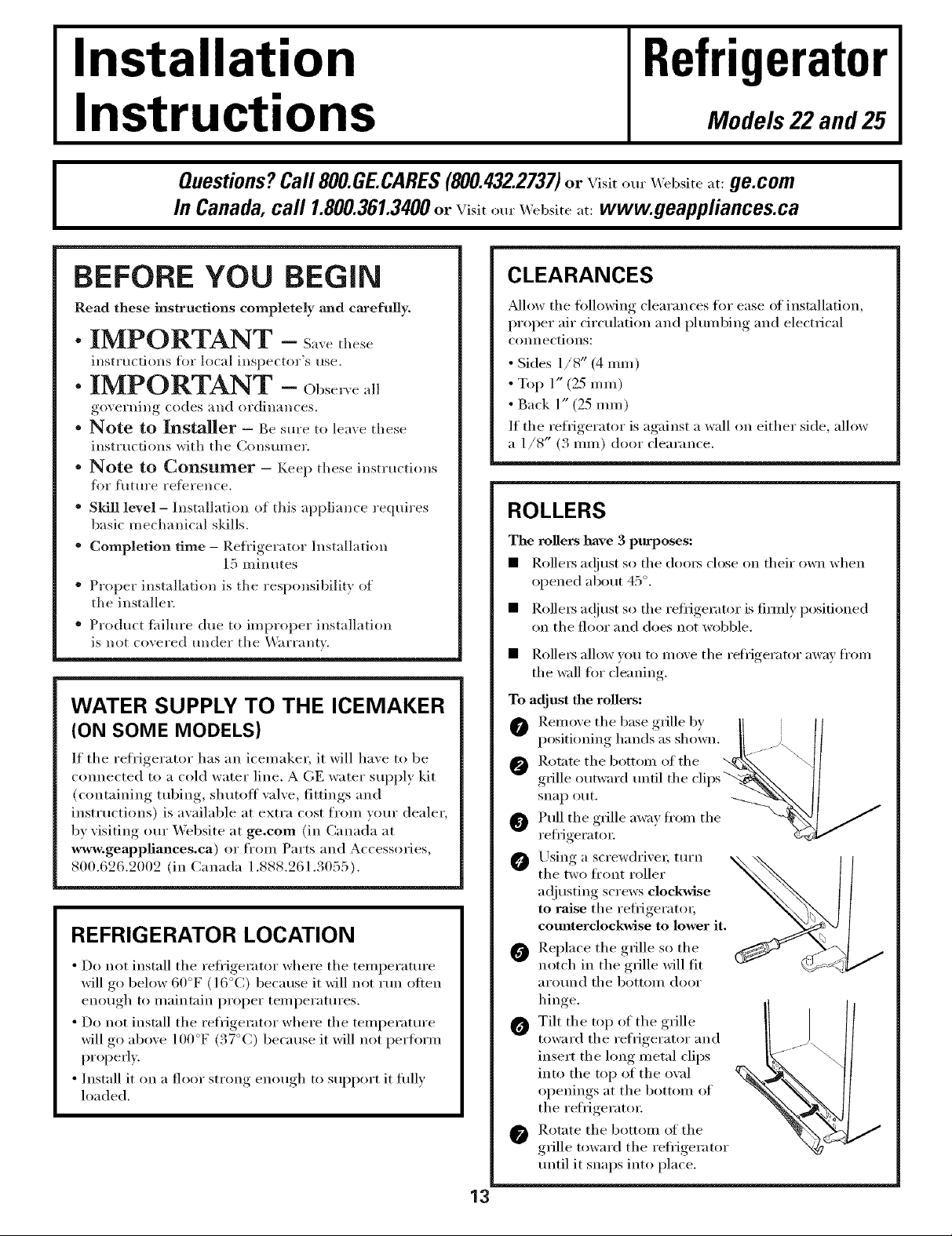
ROLLERS
The rollers have 3 purposes:
• Rollei_ ac!iust so tile dooi_ close on their own when
opened about 45 °.
• RolleI_ a@ust so tile refl-igerator is filmly positioned
on tile floor aim does not wobble.
• Rollei_ allow ) ou to u/ox e the refrigerator awa) fl'on_
the wall for cleaning,
To adjust the rollers:
O Removethebaseg_lleb, II l/
positioning hands as shown. II _/ ||
0 _'_lle""_wa"d"I"ilthe"liI)s%\ tl
s.apo.t.
0 /
refl_igeratoi: c.;_,, ,_
/_.rsing a screwdrixei; turn _
tile two ti'ont roller
a(!justing screws clockwise
to raise the refi_igei'atoi,
comlterclockwise to lower it.
Replace the grille so the
notch in tile grille will fit
aro/md tile bottoln door
hinge.
0 Tilt the top of the grille
toward tile refrigerator aim
insert the long metal clips
into tile top of tile owd
oi)enings at tile bottoln of
tile reti-igeratoi:
Rotate tile bottoln of tile
grille toward tile refi'igerator
until it snaps into place.
I
/
13
Installation instructions
iNSTALLiNG THE WATER LiNE (ONSOMEMODELS)
BEFORE YOU BEGIN
Recommended copper water supply kits are WXSX2,
WXSX3 or WXSX4, depending on the amount of
tubing you need. Approved plastic water supply lines
are GE SmartConnect'" Refl'igerator Tubing
(WX08X10002, WX08X10006, WX08X10015 and
WX08X10025).
When connecting your reh'igerator to a GE Reverse
Osmosis l,Llter S}_stem, the only approved installation
is with a GE RV/<it. For other reverse osmosis water
systems, fl)llow the mantffhcturer's recommendations.
This water line installation is not warranted by the
refrigerator or icemaker manufimmrer. Follow these
instructions carehdly to minimize the risk of expensive
water damage.
_Aater hammer (water banging in the pipes) in house
plmnbing can cause damage to refl'igerator parts and
lead to water leakage or flooding. Call a qualified
plmnber to correct water hammer beflwe installing
the water supl_ly line to the refl'igerator.
To prevent burns and product damage, do not hook
up the water line to the hot water line.
If you use vom" refl'igerator before comlecting the
water line, make sm'e the icemaker power switch is
in the 0 (of[} position.
Do not install the icemaker robing in areas where
temperatures thll below fl'eezing.
When using any electrical device (such as a power
drill) during installation, be sm'e the device is double
insulated or gr(mnded in a maxmer to prevent the
hazard of electric shock, or is batte_ T powered.
All installations must be in accordance with local
phm_bing code requirements.
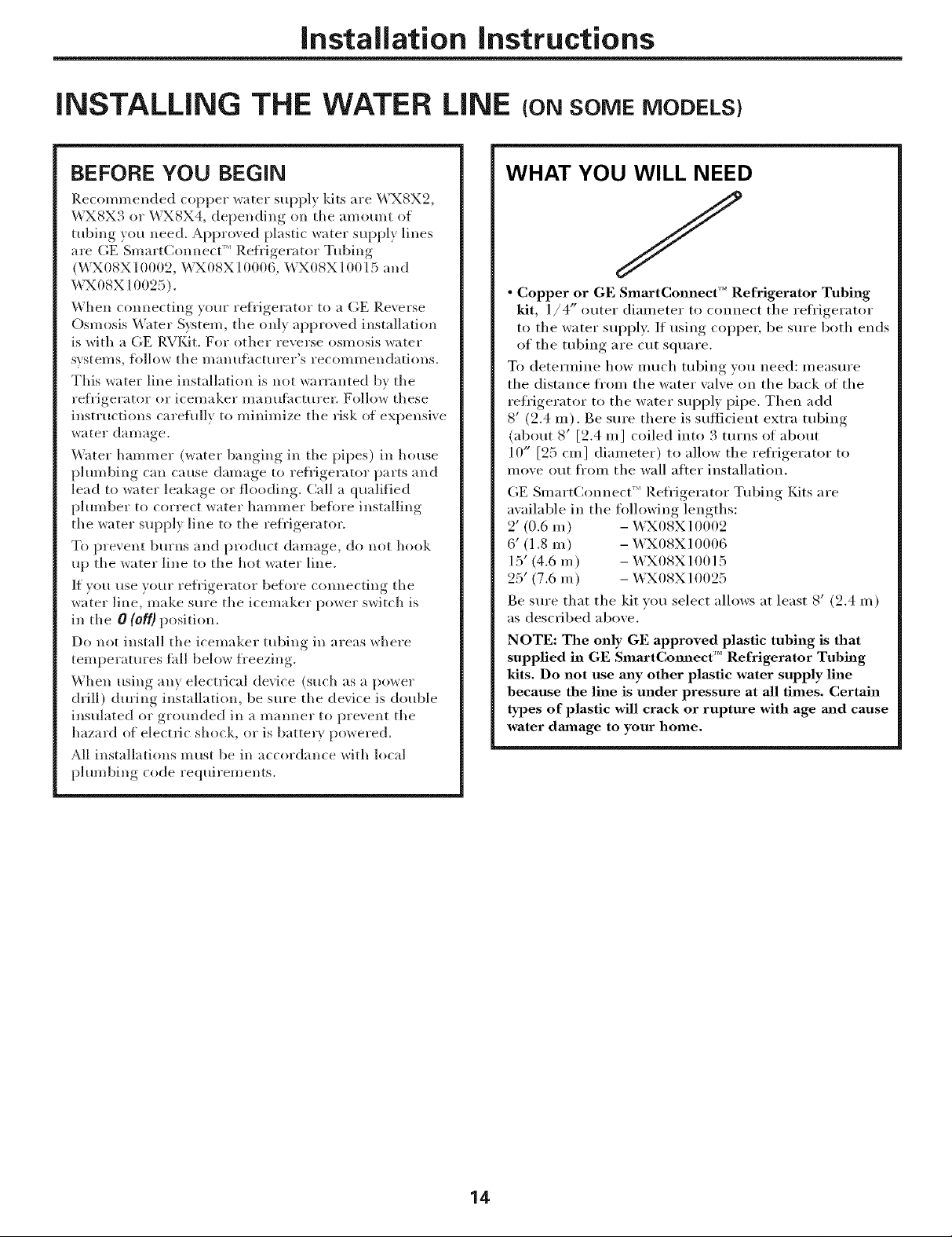
WHAT YOU WILL NEED
/
• Copper or GE SmartConnect '' Refrigerator Tubing
kit, l/4" outer diameter to connect the refi'igerator
to the water supply. If using copper, be sm'e both ends
of the tubing are cut square.
To determine how much robing you need: measure
the distance from the water wdve on the back of the
refrigerator to the water supply pipe. Then add
8' (2.4 m). Be sure there is sulticient extra robing
(about 8' [2.4 m] coiled into 3 turns of about
10" [25 cm] diameter) to allow the reh'igerator to
nlove out ti'oin the wall aDer installation.
GE Smart(hmnect'" Refl'igerator Tubing lZdts are
available in the following lengths:
2' (0.6 m) - _TX08X10002
6' (1.8 m) - WX08X10006
15' (4.6 m) - WX08X10015
25' (7.6 m) - WX08X10025
Be sure that the kit you select allows at least 8' (2.4 m)
as described above.
NOTE: The only GE approved plastic tubing is that
supplied in GE SmartComaect '_' Refrigerator Tubing
kits. Do not use any other plastic water supply line
because the line is under pressure at all times. Certain
types of plastic will crack or rupture with age mad cause
water dmnage to your home.
14
Installation instructions
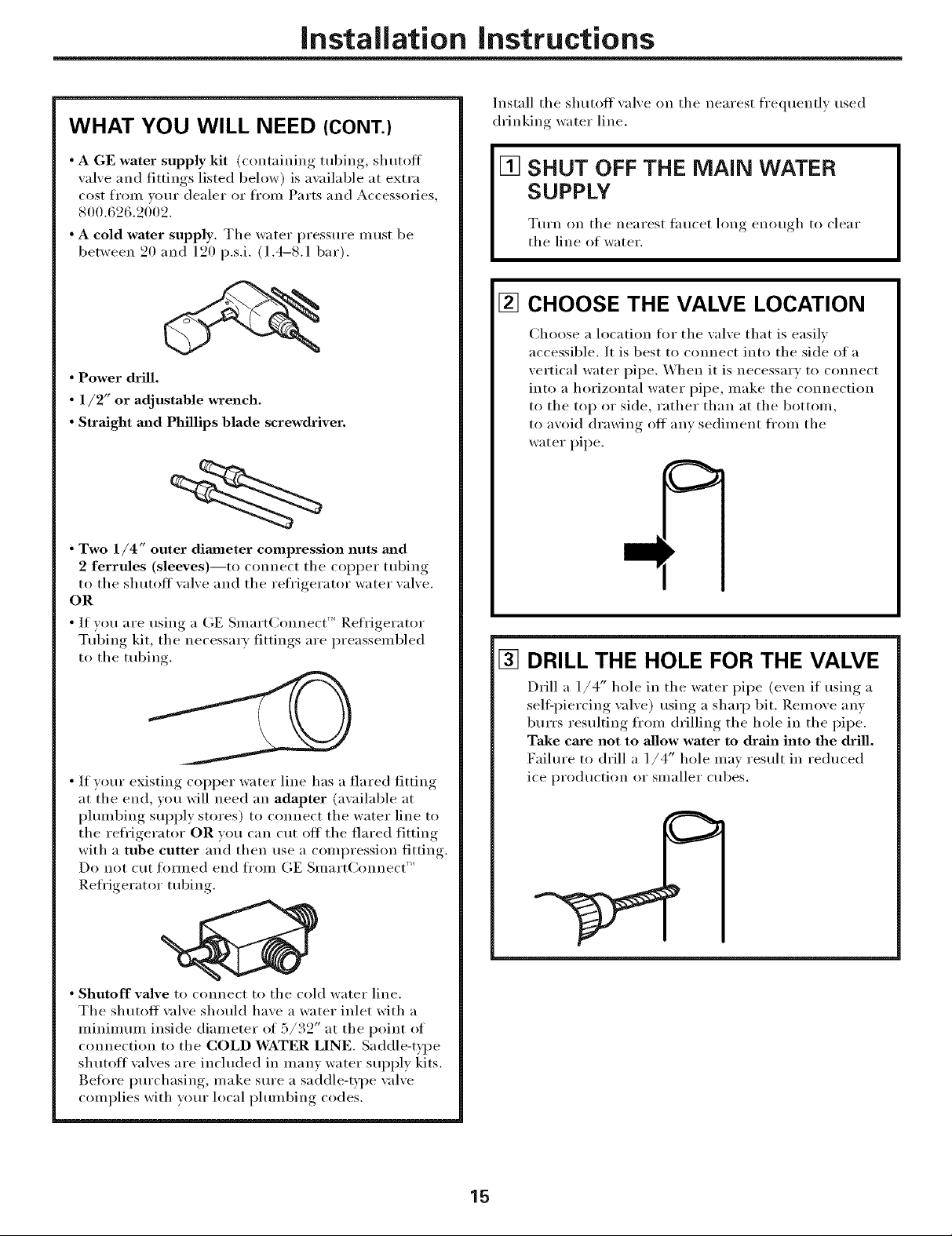
WHAT YOU WILL NEED (CONT.)
Install the shutoff valve on the nearest frequently used
drinking water line.
• A GE water supply kit (containing tubing, shutoff
valve and fittings listed below) is available at extra
cost frmn your dealer or fl'om Parts and Accessories,
800.626.2002.
• A cold water supply. The water pressure must be
between 20 and 120 p.s.i. (1.4-8.1 bar).
• Power drill.
• 1/2" or adjustable wrench.
• Straight and Phillips blade screwdriver.
• Two 1/4" outer diaaneter compression nuts and
2 ferrules (sleeves)--to connect the copper tubing
to the shutoff valve and the refrigerator water valve.
OR
• If you are usino a GE Smat t(;onnect' Refrigerator
Tubino_ kit, the necessary, fittinos_, are preassembled
to the tubing
[] SHUT OFF THE MAiN WATER
SUPPLY
Ttu'n on the nearest taucet long enough to clear
the line of water.
[] CHOOSE THE VALVE LOCATION
Choose a location fl_r the valve that is easily
accessible. It is best to connect into the side of a
vertical water pipe. When it is necessary to connect
into a horizontal water pipe, make the connection
to the top or side, rather than at the bottom,
to avoid drawing off anv sediment fl'om the
water pipe.
[] DRILL THE HOLE FOR THE VALVE
• If yotu" existing COl)per water line has a flared fitting
at the end, you will need an adapter (awfilable at
plmnbing supply stores) to connect the water line to
the refl'igerator OR you can cut off the flared fitting
with a tube cutter and then use a compression fitting.
Do not cut tom_ed end fl'om GE SmartConnect '_
Refl'igerator tubing.
• Shutoff valve to connect to the cold water line.
The shutoff wflve should have a water inlet with a
minimmn inside diameter of 5/32" at the point of
connection to the COLD WATER LINE. Saddle-type
shutoff valves are included in manv water supply kits.
getOre i)urchasing, inake sure a saddle-type valve
complies with yore" local l)hunbing codes.
Drill a 1/4" hole in the water pipe (even it using a
sell:piercing valve) using a sharp bit. Remove anv
burrs resulting fl'om drilling the hole in the pipe.
Take care not to allow water to drain into the drill.
Faihu'e to drill a 1/4" hole may result in reduced
ice production or smaller cubes.
15

Installation Instructions
iNSTALLiNG THE WATER LiNE (CONT.)
[] FASTEN THE SHUTOFF VALVE
Fasten the shutoff xalxe to the cold water pipe with
the pipe clamp.
PipeClamp_
Saddle-TypeJ -VerticalCold
ShutoffValve WaterPipe
NOTE: Conmmnwealth of Massachusetts Plumbing
Codes 248CMR shall be adhered to. Saddle wflves
are illegal and use is not permitted in Massachusetts.
(hmsult with wmr licensed plmnber.
[]
TIGHTEN THE PIPE CLAMP
Tighten tile clamp screws tmtil tile sealing washer
begins to swell.
NOTE: Do not overtighten or you may c_ush tile
tubing.
Pipe
Clamp
Washer
[] CONNECT THE TUBING
TO THE VALVE
Place tile compression nut and tiq'_ ule (sleexe)
fi)r COl)per tubing onto tile end of tile tubing and
connect it to tile shutoff xalxe.
Make sm'e tile tubing is flflly inserted into tile valve.
Tighten the compression nut secm'elv.
D)r plastic tubing fl'om a (kE SmartConnect ''_
Refl'igerator Tubing kit, insert tile molded end
of the robing into the shutoff wflve and tighten
compression nut tmtil it is hand tight, then tighten
one additional turn with a wrench. Overtightening
Ill'IV CatlSe leaks.
Saddle-Type
ShutoffValve ,,_
Packing Nut--
OutletValve-- -- Ferrule(sleeve)
NOTE: Commonwealth of Massachusetts Plmnbing
Codes 248CMR shall be adhered to. Saddle valves
are illegal and use is not permitted in Massachusetts.
Consult with yore" licensed plmnbe_:
3ression
Nut
SmartConnect_
Tubing
[] ROUTE THE TUBING
Route tile tubing between tile cold water line and
tile refl'igera tot.
Route tile tubing through a hole drilled in tile wall
or floor (behind tile refrigerator or ac!jacent base
cabinet) as close to tile wall as possible.
NOTE: Be sure there is sufficient extra tubing
(about 8 feet [944 cm] coiled into 3 turns of about
10" [25 cm] diameter) to allow the refl'igerator to
move out fl'oln tile wall after installation.
[] FLUSH OUT THE TUBING
Turn tile main water sui_ply on and flush out tile
tubing tmtil tile water is clear.
Sh lit the water off at the water valve after about
one quart (l liter) of water has been flushed
through tile tubing.
16
Installation Instructions
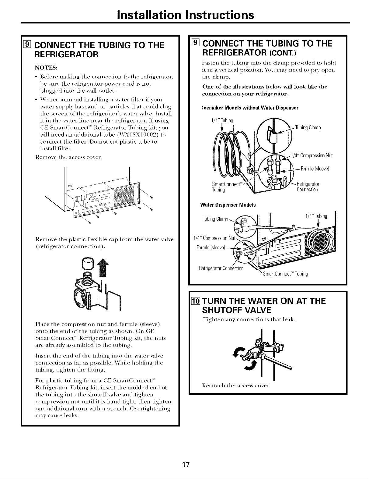
[] CONNECT THE TUBING TO THE
REFRIGERATOR
NOTES:
• getore making tile connection to tile reti'igerator,
be sure tile refl'igerator power cord is not
plugged into the wall outlet,
• We recommend installing a water filter if w)tu"
water sui)ply has sand or particles that could clog
the screen of the refl'igerator's water wdve. Install
it in the water line near the refrigerator. If using
GE SmartConnect '_ Refl'igerator Tubing kit, you
will need an additional tube (WX08X10009) to
connect tile filter. Do not cut plastic tube to
install filter.
Reillo_,e tile access co_,ei',
[] CONNECT THE TUBING TO THE
REFRIGERATOR (CONT.)
Fasten tile tubing into tile clamp provided to hold
it in a vertical position. You may need to PU open
tile clamp.
One of the illustrations below wiU look like the
connection on your refrigerator.
Icemaker Models without Water Dispenser
1/4"Tubing
)nNut
(sleeve)
SmartC_
Tubing
Water DispenserModels
TubingClamp...
- Refrigerator
Connection
Remove tile plastic flexible cap from tile water xalve
(refrigerator connection).
©
Place tile compression nut and ferrule (sleeve)
onto the end of the tubing as shown, On GE
SmartConnect _'' Refl'igerator Tubing kit, tile nuts
are ah'eadv assembled to tile tubing.
Insert tile end of tile tubing into tile water wdve
connection as thr as possible. While holding the
tubing, tighten tile fitting.
For plastic tubing fl'om a GE Smart(:mmect ''_
Refl'igerator Tubing kit, insert tile molded end of
the tubing into the shutoff wdve and tighten
compression nut tmtil it is hand tight, then tighten
one additional turn with a wrench, Overtightening
Ill}IV catlse leaks,
1/4"CompressionNut,
Refrig
SmartC innect _ Tubing
1/4"Tubir_
[] TURN THE WATER ON AT THE
SHUTOFF VALVE
Tighten am connections that leak.
Reattach tile access cover.
17
Installation Instructions
INSTALLING THE WATER LINE (CONT.)
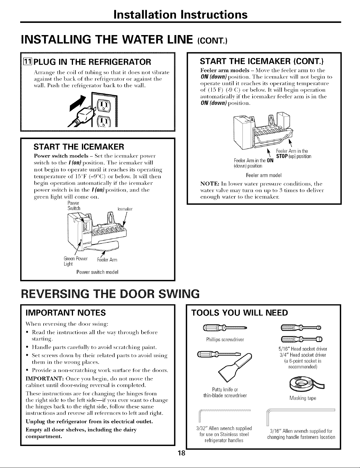
[] PLUG IN THE REFRIGERATOR
Arrange the coil of tubing so that it does not _ibrate
against the back of the refrioerator_ or against, the
wall, Push the refrigerator back to the wall,
START THE ICEMAKER
Power switch models - Set the icemaker power
switch to the I (on) position, The icelnaker will
not begin to operate until it reaches its operating
temperatm'e of 15°F (-9°C) or below, It will then
begin operation automatically if the icemaker
power switch is in the I (on) position, and the
green light will come on.
Power
Switch icemaker
START THE ICEMAKER (CONT.)
Feeler arm models - Move the libeler arm to the
ON (down) position. The icemaker will not begin to
operate until it reaches its operating temperatm'e
of (l 5 F) (-9 C) or below. It will begin operation
automatically if the icemaker feeler am_ is in the
ON (down) position.
_min the
FeelerArmintheON
(down)position
Feelerarmmodel
NOTE: In lower water pressure conditions, the
water ",al',e may turn on up to 3 times to delixer
enotloh water to the icelllakei:
STOP(up)position
Light
Powerswitch model
REVERSING THE DOOR SWING
IMPORTANT NOTES
When re\'e_Mng the door swing:
• Read the instructions all the way through belore
starting.
• Handle parts careflfllv to avoid scratching paint.
• Set screws down bv their related parts to avoid using
them in the wrong places.
• Provide a non-scratching work surtace fro" the doors.
IMPORTANT: Once you begin, do not move the
cabinet tmtil doo>swi_g reversal is completed.
These instructions are for changing the hinges fl'om
the right side m the lett side---if wm ever want to change
the hinges back to the right side, tollow these same
instructions and reverse all reterences to lett and right.
Unplug the refrigerator from its electrical outlet.
Empty all door shelves, including the dairy
compartment.
TOOLS YOU WILL NEED
Phillipsscrewdriver
5/16" Headsocketdriver
3/4" Headsocketdriver
Puttyknifeor
thin-bladescrewdriver
3/32" Allen wrenchsupplied
foruseon Stainlesssteel
refrigeratorhandles
3/16"Allen wrench suppliedfor
changinghandlefastenerslocation
(a&point socketis
recommended)
Maskingtape
18
Installation instructions
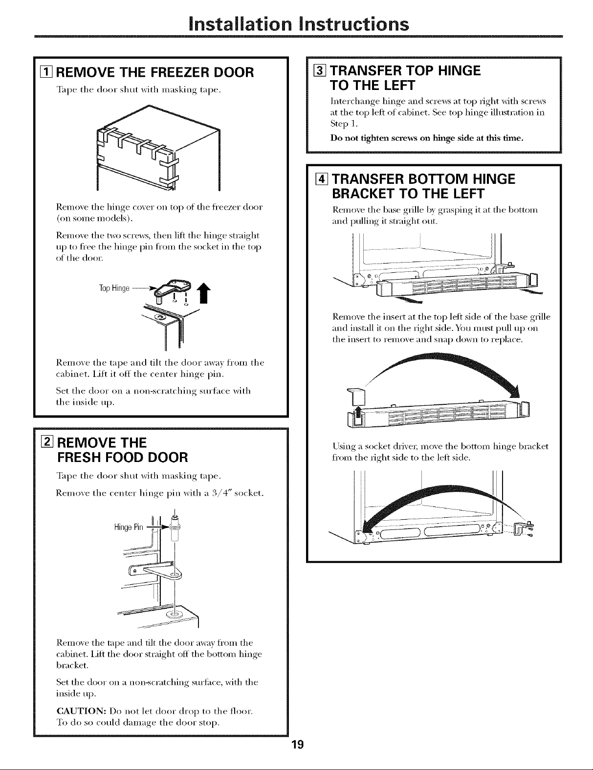
[] REMOVE THE FREEZER DOOR
%q_e the door shut with masking tape.
I).emoxe the hinge coxer on top of the fl'eezer door
(on some models).
Ilemo_e the two screws, then lift the hinge straight
ui ) to fl'ee the hinge, pin ti'om the socket in the top
of the doo_:
[] TRANSFER TOP HINGE
TO THE LEFT
Interchange hinge and screws at top fight with scre_vs
at the top left of cabinet. See top hinge illustration in
Step 1.
Do not tighten screws on hinge side at this time.
[] TRANSFER BOTTOM HINGE
BRACKET TO THE LEFT
Remo_ e the base ,grille by,,graslring, it at the bottom
and pulling it straight out.
Remoxe the insert at the top left side of the base grille
and install it on the fight side. You must pull up on
the insert to remoxe and snap down to replace.
Remove the tape and tilt the door away fl'om the
cabinet, i,ifl it off the center hinge pin.
Set the door on a non-scratching surtace with
the inside up.
[] REMOVE THE
FRESH FOOD DOOR
Tape the door shut with masking tape.
Remoxe the center hinoe_ pin with a ,/4 socket.
H" m,
inge_rln7
Remoxe the tape and tilt the door mva} fl'om the
cabinet, i,ifl the door straight off the bottom hinge
bracket,
Using a socket drixe_; moxe the bottom hinge bracket
ti'om the rioht side to the left side.
tt
Set the door on a non-scratching sm'face, with the
inside up.
CAUTION: Do not let door drop to the floor.
To do so could damage the door stop.
19
Installation Instructions
REVERSING THE DOOR SWING (CONT.)
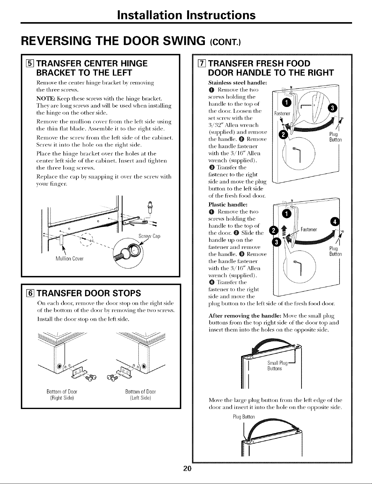
[] TRANSFER CENTER HINGE
BRACKET TO THE LEFT
]_.emove the (enter hinge bracket by removing
the three screws,
NOTE: Keep these screws with the hinge bracket.
They are long screws and will be used when installing
the hinge on the other side.
Remove the mullion cover fl'om the left side using
the thin fiat blade. Assemble it to the right side.
Remove the screw from the left side of the cabinet.
Screw it into the hole on the right side.
Place the hinge bracket over the holes at the
center left side of the cabinet. Insert and tighten
the three long screws.
Replace the cap by snapping it over the screw with
yore" finger.
[] TRANSFER DOOR STOPS
On each d()(m remoxe the door stop on the right side
of the bottom of the door bx remoxino the two screws.
Install the door stop on the left side.
• 0
[] TRANSFER FRESH FOOD
DOOR HANDLE TO THE RIGHT
Stainless steel handle:
O Renl(we the two
screws holding the
handle m the top of
the dora: I,oosen the
set screw with the
3/32" Mlen wrench
(supplied) and remove Plu
the handle, 0 Remove Button
the handle fastener
with the. /lb Mlen
wrench (supplied).
Transter the
ti_stener to the right
side and move the plug
button to the left side
ot the fl'esh food dora:
Plastic hmadle:
Remove the two
scrmvs holding the
handle to the top of
the dora: _ Slide the
handle up on the
ti_stener and remove Plug
the handle, _ Remove Button
the handle fastener
with the 3/16" Mien
wrench (supplied).
Tmnstbr the
ti_stener to the right
side and move the
plug button to the left side of the fl'esh ti)()(1 doo_:
After removing the handle: Move the small plug
buttons fl'om the top right side of the door top and
insert them into the holes on the opposite side,
Bottomof Door
(RightSide)
Bottomof Door
(LeftSide)
SmallPlu,
Buttons
Move the large plug button fl'om the left edge of the
door and insert it into the hole on the opposite side.
PlugButton
I
2O
Installation Instructions
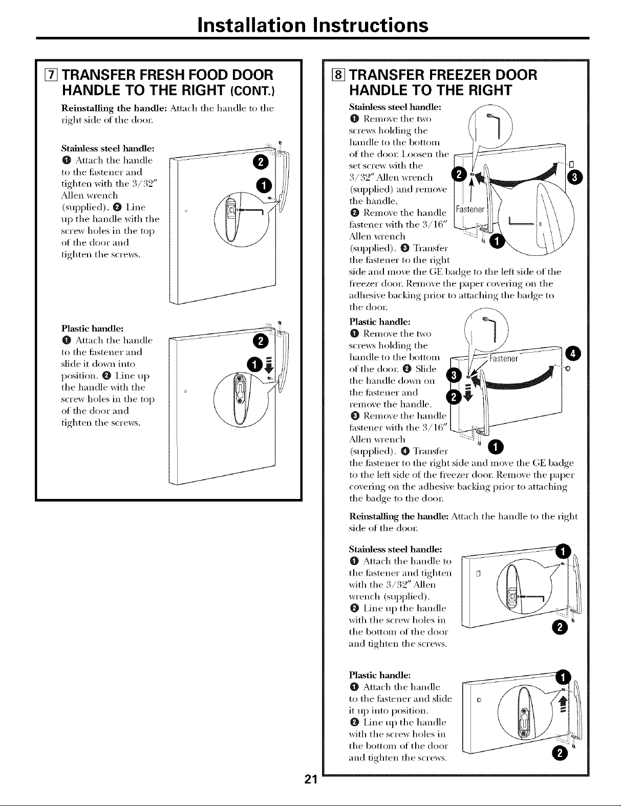
[] TRANSFER FRESH FOOD DOOR
HANDLE TO THE RIGHT (CONT.)
Reinstalling the handle: Attn(h tile handle to tile
right side oI tile do(n:
Stainless steel hm_dle:
O Attach tile handle
to tile ti_stener and
tighten with the 3/32"
Allen wrench
(supplied). O I,ine
up the handle with the
screw holes in the top
of tile door and
tighten the screws.
Plastic hm_dle:
Attach tile handle
to tile tilstener and
slide it down into
position. _ I,ine up
tile handle with tile
screw holes in tile top
of tile door and
tighten tile screws.
jJ
J
J
[] TRANSFER FREEZER DOOR
HANDLE TO THE RIGHT
Stainless steel hmldle:
O Remove tile two
screws holding tile
handle to tile bottom
of the do(n; I,oosen the
set screw with tile -0--
3 j 3.......
• /. Z _AlleI1 wrench
(supplied) and rei//o_e
O Remove tile handle
ti_stener with tile. / /o
tile handle. 1
Allen wrench
(supplied). O Transter
tile fl_stener to tile right
side and move tile GE badge to tile left side of tile
ti'eezer dora: Remove tile paper covering on tile
adhesive backing prior to attaching tile badge to
tile doo_:
Plastic hm_dle:
Remove tile two
screws holdino tile
handle to tile bottom Fastener 0
of the dora: _ Slide
tile handle down on
tile fl_stener and
remo,,e the handle.
Remove tile handl_
fi_stener with tile 3/16"
Mien wrench
(supplied). _ Transli_r
the fl_stener to the right side and move the GE badge
to the left side of the fl'eezer door; Remove the paper
coveting on tile adhesive backing prior to attaching
tile badge to tile do(n;
O
21
Rehlstall_lg the handle: Attach the handle to the right
side of tile do(n:
Stainless steel hm_dle:
O Attach tile handle to
tile ti_stener and tighten
with tile 3/32" Mien
wrench (sui_plied).
IJne up tile handle
with the screw holes in
tile bottom of tile door
@
and tighten tile screws.
Plastic hmadle:
Attach tile handle
to tile fiastener and slide
it up into position.
IJne up the handle
with the screw holes in
the bottom of the door
and tighten tile screws.
@
Installation Instructions
REVERSING THE DOOR SWING (CONT.)
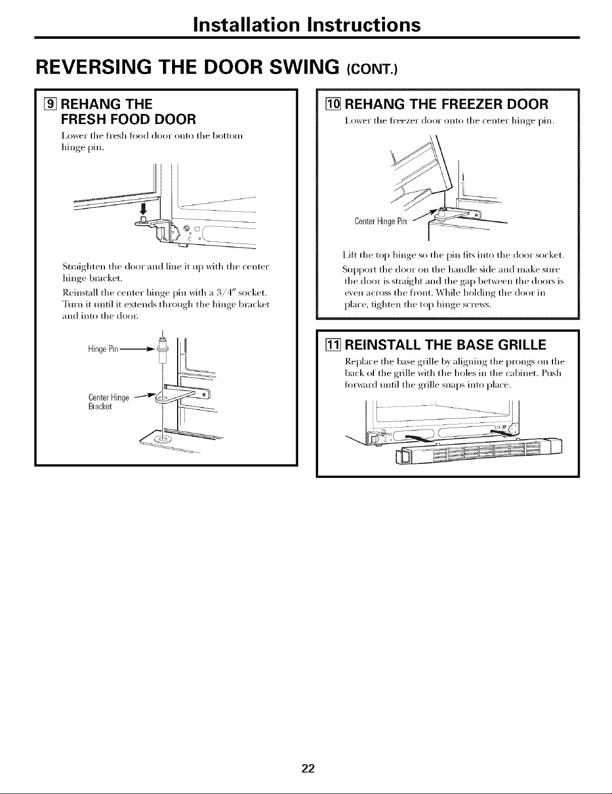
[] REHANG THE
FRESH FOOD DOOR
I,ower tile h'esh _()od dooI" onto tile bottoIll
hinge pin.
Straighten the door and line it up with the center
hinge bracket.
Reinstall the center hinge pin with a 3/4" socket.
Turn it until it extends through the hinge bracket
and into the dora:
L
CenterHinge
Bracket
[] REHANG THE FREEZER DOOR
I,ower the fl'eezer door onto the center hinge pin.
CenterHingePin
i,ift the top hinge so the pin fits into the door socket.
Support the door on the handle side and make sm'e
the door is straight and the gap between the dom_ is
e\'en across the front. While holding the door in
place, tighten the top hinge scre_vs.
[] REINSTALL THE BASE GRILLE
Rei)lace the base ,grille by,alionino__ the I)r°ngs, on the
back of the grille with the holes in the cabinet. Push
forward tmfil the grille snaps into place.
22
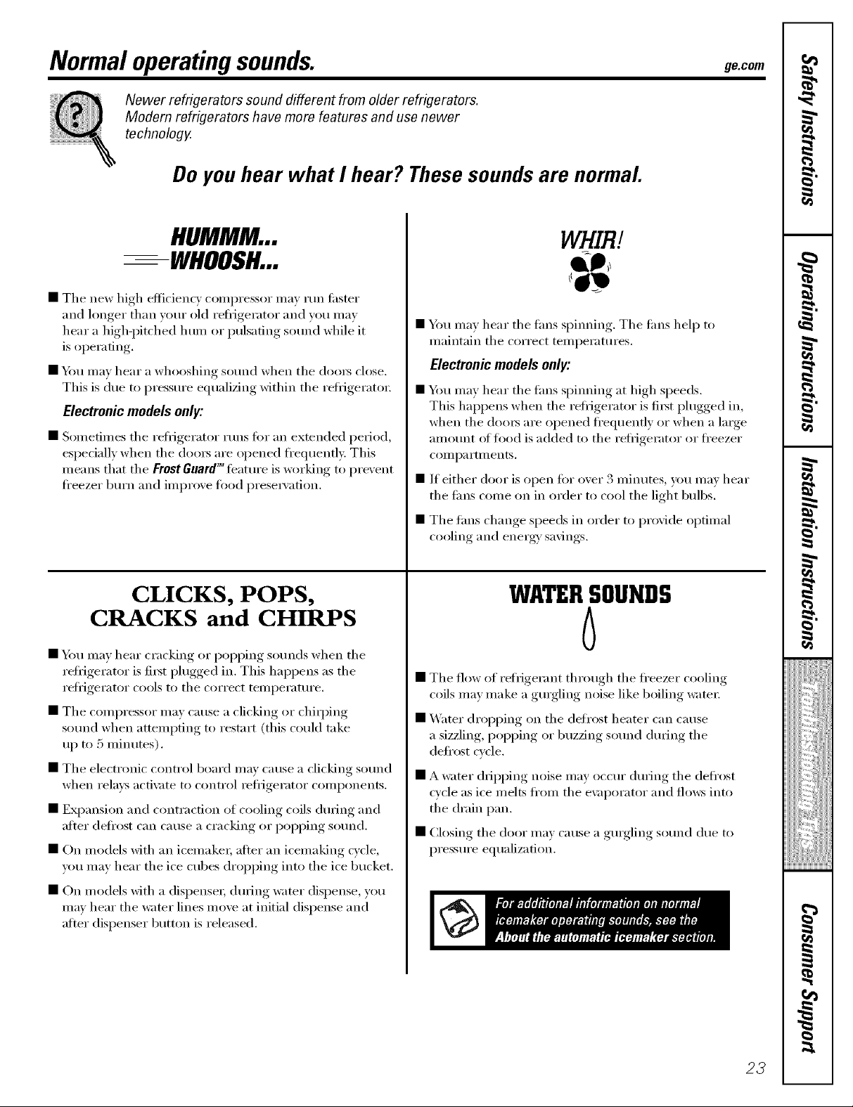
Normal operatingsounds. Decorn
Newer refrigerators sound different from older refrigerators.
Modem refrigerators have more features and use newer
technology.
Do you hear what I hear? These sounds are normal.
HUMMM...
--WHOOSH...
• Tile new high efficiency compressor may run fi_ster
and longer than your old refl_gerator and you may
hear a high-pitched hum or pulsating sound while it
is operating.
• You may hear a whooshing sound when tile doo_ close.
This is due to pressure equalizing within tile reti_igerato_:
Electronic models only:
• Sometimes tile reflJgerator runs fin" an extended period,
espedally when tile doo_ are opened ti'equentl}: This
means that tile Frost GuardT"fbatm'e is working to prevent
ti'eezer b/:u'n and improve food prese_'ation.
CLICKS, POPS,
CRACKS and CHIRPS
• Ym may hear cracking or popping so/mds when tile
reti_igerator is fi_t plugged in. This happens as tile
i'eliJgei'ator cools to tile coFi'ect teillpei'attli'e.
• Tile compressor may cause a clicking or chiq)ing
so/md when attempting to restart (this could take
up to 5 minutes).
• Tile electronic control board may cause a clicking sound
when relays acti\me to control reti_igerator components.
• EN)ansion and contraction of cooling coils during and
after delix)st can Catlse a ci'acking or popping SOtlnd.
• On models with an icemake_; after an icemaking cycle,
um may hear tile ice cubes dropping into tile ice bucket.
WHIRl
54m may hear tile rims 'IS/innin_.* Tile rims help to
maintain tile correct temperatm'es.
Electronic models only:
• Y)m may hear tile rims spinning at high speeds.
This happens when tile reti_igerator is fiI_t plugged in,
when tile (loo_ are opened fl'equenfly or when a lmge
amo/mt ot tood is added to tile refl_igerator or fl'eezer
COIIlp_l I'tlIleIltS.
• If either door is open fin" over 3 minutes, you may hear
tile tiros come on in order to cool tile light bulbs.
• Tile rims change speeds in order to provide optimal
cooling and energo' savings.
WATERSOUNDS
6
• The flow of refrigerant through tile fl'eezer cooling
coils may make a gmgling noise like boiling water:
• Water dropping on tile deti'ost heater can cause
a sizzling, popping or buzzing sound dtwing tile
defl'ost cycle.
• A water dripping noise may occur during tile defl'ost
cycle as ice melts ti'om tile e\:q)orator and flo_:s into
tile drain pan.
• Closing tile door may cause a gmgling so/md due to
pressure equalization.
• On models with a dispense_; (hwing 'wamr dispense, you
may hear tile water lines move at initial dispense and
after dispenser button is released.
23
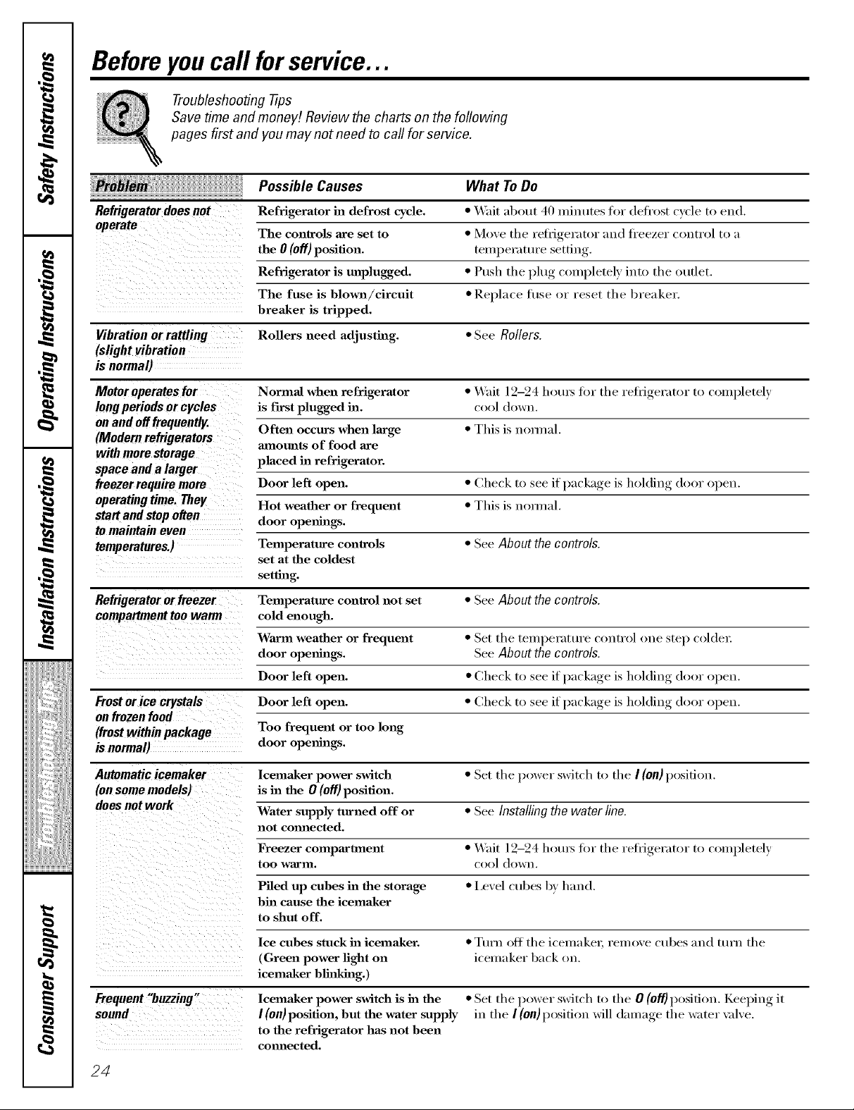
Beforeyoucall forservice...
Troubleshooting .tips
Save time and money/. Review the charts on the following
pages first and you may not need to call for service.
Possible Causes
Refrigerator does not Refrigerator in defrost cycle. * Wait about 40 minutes for defl'ost cycle to end.
The controls axe set to * Move tile refl'igerator and fl'eezer control to a
What ToDo
the0(o.)position. e,.t.re et i,l
Refrigerator is tmplugged. • Push tile I)lu°_ completely, into tile outlet.
The fuse is blown/cireuit * Replace rise or reset the breaker.
breaker is tripped.
Vibration or rattling Rollers need adjusting. • See Rollers.
(slight vibration
is normal)
Motor operates for Normal when refrigerator • _fit 12-24 hom_ fin" tile refl_igerator to completely
long periods or cycles is first plugged in. cool down.
on and offfrequentlg Often occurs when large • This is nomml.
(Modern refrigerators mnotmts of food axe
with more storage
space and a larger placed in refrigerator.
treezerrequire more Door left open. • Check to see if I)ackage, is holding door open.
operating time, They Hot weather or frequent • This is nomml.
start and stop often door ope_fings.
tomaintain even
temperatures.) Telnperature controls * See About the controls.
Refrigerator orfreezer Temperature control not set • See About the controls.
set at the coldest
setting.
cold enough.
WaJcm weather or frequent • Set tile temperatm'e control one step col(le_:
door opetm,_. See Aboutthe controls.
if )ackaoe is holding door open.Door left open. • Check to see [ _ ,
Door left open. * Check to see if I)ackage, is holding door open.
(frost within package Too frequent or too long
is normal) door ope_fings.
Automatic icemaker lcema.ker power switch * Set the power switch to the I(on) position.
(onsome models) is in the 0 (off) position.
does not work Water supply turned off or * See Installing the water line.
not comlected.
Freezer compm'tment • _,_fit 12-24 houI_ for tile refi_igerator to completely
too warln, cool down,
Piled up cubes in the storage • I,exel cubes 1)_hand.
bin cause the icema_ker
to shut off.
Ice cubes stuck in icema_ker. • Turn off tile icemake_, remoxe cubes and tm'n tile
(Green power light on icemaker back on.
icema_ker blinking.)
Frequent"buzzing.
sound
lcema_ker power switch is in the
I (on) position, but the water supply
to the refrigerator has not been
com_ected.
• Set tile power switch to tile 0 (off) position. Keelfin(*,. it
ill tile I(on)position will dalnage tile water x ilxe.
24
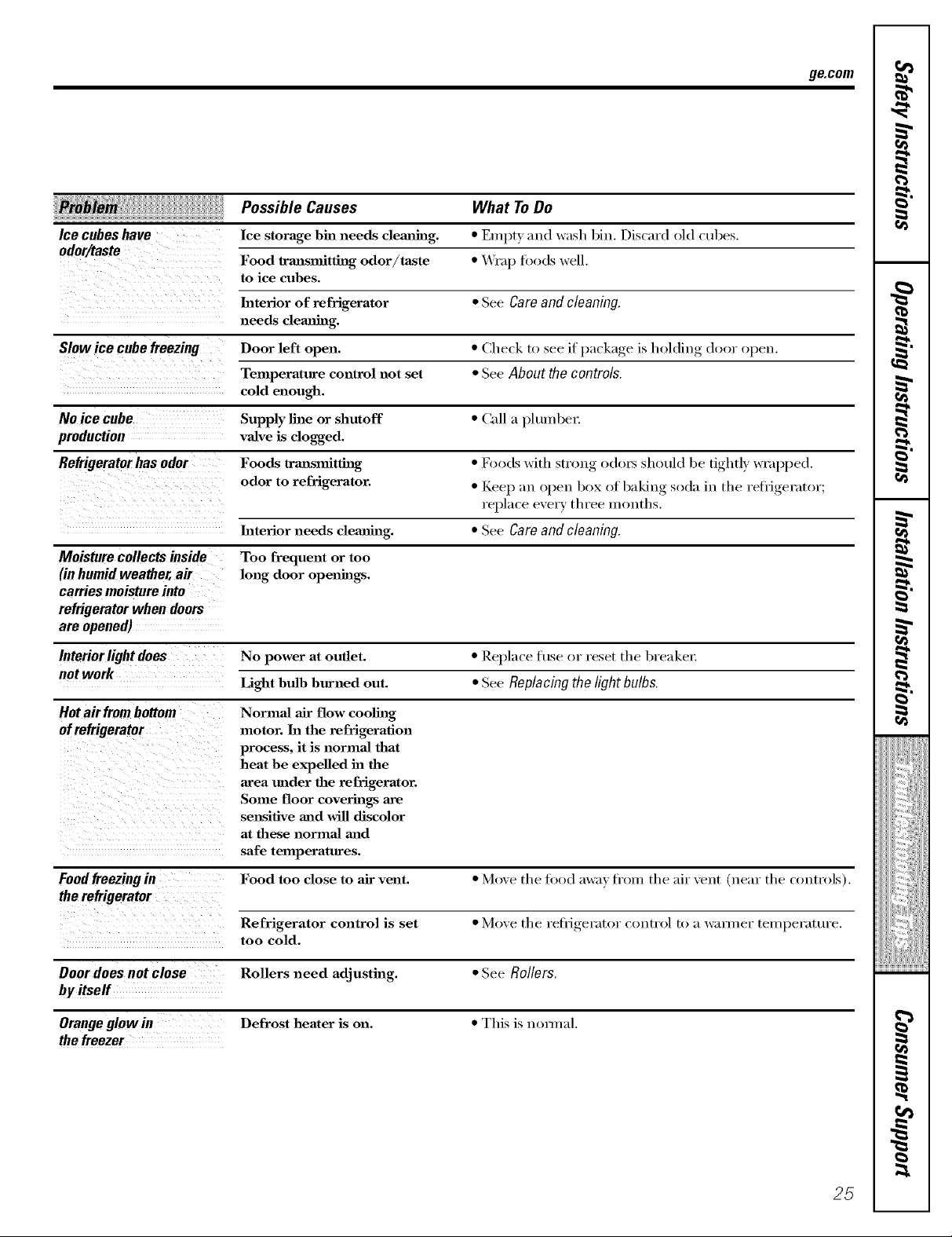
Possible Causes What ToDo
Ice cubes have Ice storage bin needs cleaalhzg. * Erupt) and wash bin. Discard old cubes.
Food traalsmitthag odor/taste * _'rap fi)ods well.
to ice cubes.
Interior of refrigerator * See Careandcleaning.
needs clemlhzg.
Slowice cube freezing Door left open. * Che(& to see if I_ackage, is holding d,,or (,pen.
Temperature control not set * See About the controls.
cold enough.
NOice cube Supply line or shutoff * Call a plumbe_:
production vaJve is clogged.
Refrigerator has odor Foods trm_smitth_g * Foods with strong o(hn_ should be tightl) wrapped.
odor to refrigerator. * Keep an oI)en box of baking, soda in the refl_gerator;
replace exerv three months.
Interior needs clemlh_g. * See Care and cleaning.
Moisturecollectsinside Too frequent or too
(in humid weather, air long door openings.
carries moisture into
refrigerator when doors
are opened)
go.corn
Interiorlightdoes No power at outlet. * Replace fuse or reset the breaker;
notwork
Hot airfrom bottom NormaJ air flow coolh_g
Foodfreezing in Food too close to air vent. * Move the fi)od axvax fl'om the air vent (near the controls).
Door does not close Rollers need adjusting. * See Rollers.
by#self
Orange glowin Defrost heater is on. * This is n(mnal.
the freezer
Light bulb burned out. * See Replacing the light bulbs
motor. In the refrigeration
process, it is normal that
heat be expelled in the
area under the refrigerator.
Some floor coverings axe
sensitive and will discolor
at these normal mid
safe temperatures.
Refrigerator control is set * Moxe the refl_igerator control to a wmmer temperature.
too cold.
i_i_}iiiiiJiiiiiiii_i_i
i/iiii i i__
25
i
Beforeyoucall forservice...
Troubleshooting -tips
Possible Causes What ToDo
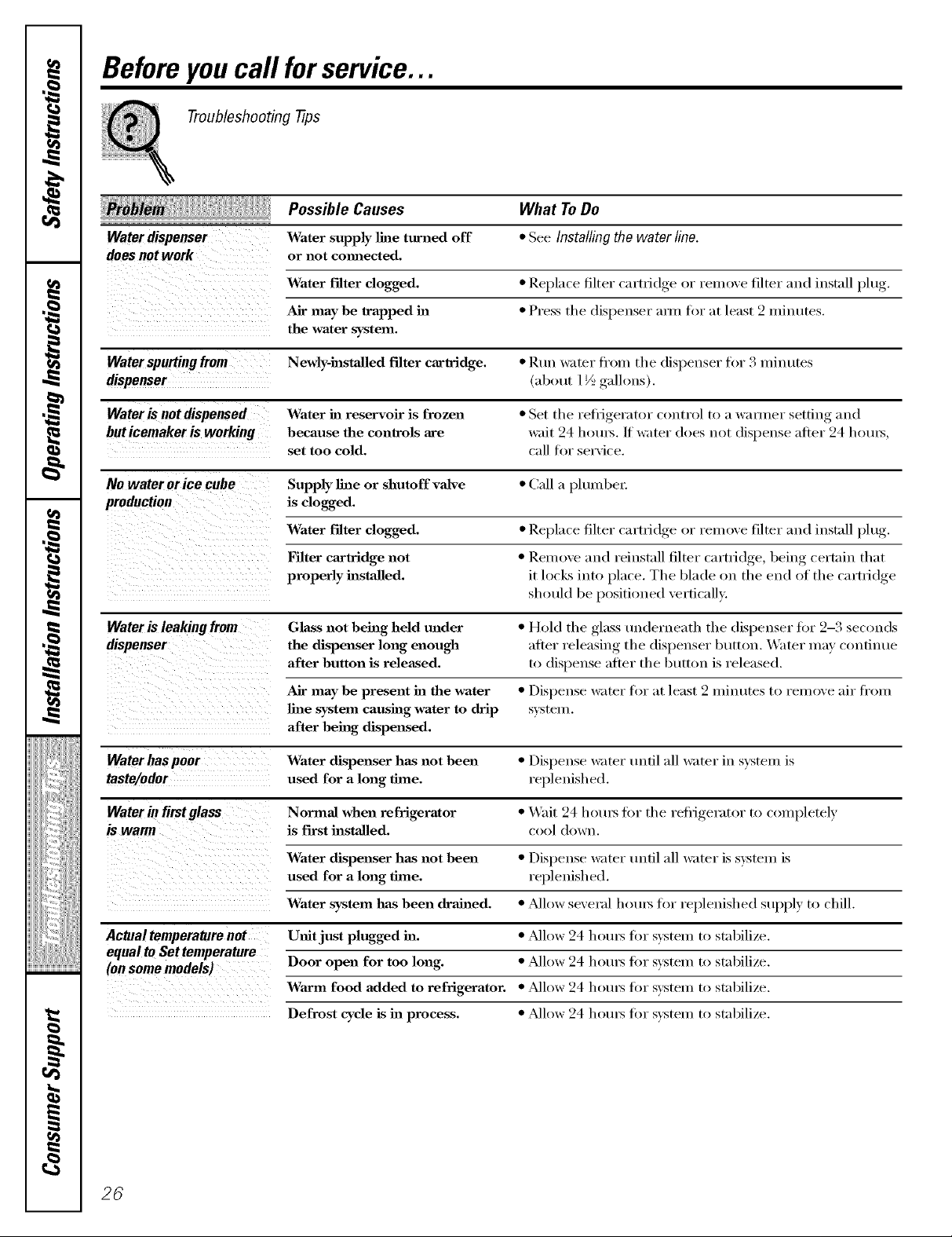
Water dispenser Water supply line turned off * See Installing the water line.
does not work or not cmmected.
Water filter clogged. * Replace filter (am_idge or remove filter and install })lug>
Air may be trapped ha * Press the dispenser ami fl)r at lea,4 2 minutes,
the water system.
Waterspurting from Newly-hastaUed filter cartridge. * Ruu water fl'om the dispenser for 3 minutes
dispenser (about 1½ gallons).
Wateris not dispensed Water in reservoir is frozen * Set the reii_igerator control to a wamier setting and
buticemakeris working because the controls are wait 24 houl_./f water does not dispense after 24 houl_,
set too cold. call for service.
No water orice cube Supply line or shutoff valve * Call a plumbe_:
production is clogged.
Water filter clogged. * Replace filter cam-id(,e_ or remove filter and install lflu_'
S • "
Filter cartridge not * Remove and reinstall, filter cartridoe,_ beiu(_ certain that
properly hastalled, it locks into place. The blade on the end of the cartridge
should be positioned vertically..
Water is leaking from Glass not being held under * Hold the glass tmderueath the dispenser fi)r 2-3 seconds
dispenser the dispenser long enough after releasing the dispenser button. Water may continue
after button is released, to (lispeuse after the butt(m is released.
Air may be present ha the water * Dispense water fi)r at least 2 minutes to remove air fl'om
line system causing water to drip system,
after being dispensed.
Water has poor Water dispenser has not been * Dispense water until :ill water in system is
taste/odor used for a long time, replenished.
Water in first glass Normal when refrigerator * \4air 24 h()tu_ fl)r the refiigerat()r t() c()Iupletely
is First hastalled, c()()l (h)wn.
Water dispenser has not been * Dispense water tmfil :Ill water is system is
used for a long time, replenished.
Water system has been drained, * _Mlow several l/otus for replenished supply to chill.
Actual temperature not U_fit just plugged ha. * _dlow 24 horus fin" system to stabilize.
equalto Set temperature
(on some models) Door open for too long. * Alh)w 24 l/()tu_ fl)r system t() stabilize.
Warm food added to refrigerator. * _Mlow 24 horus fin" system to stabilize.
Defrost cycle is ha process. * Allow 24 horus fin" system to stabilize.
26
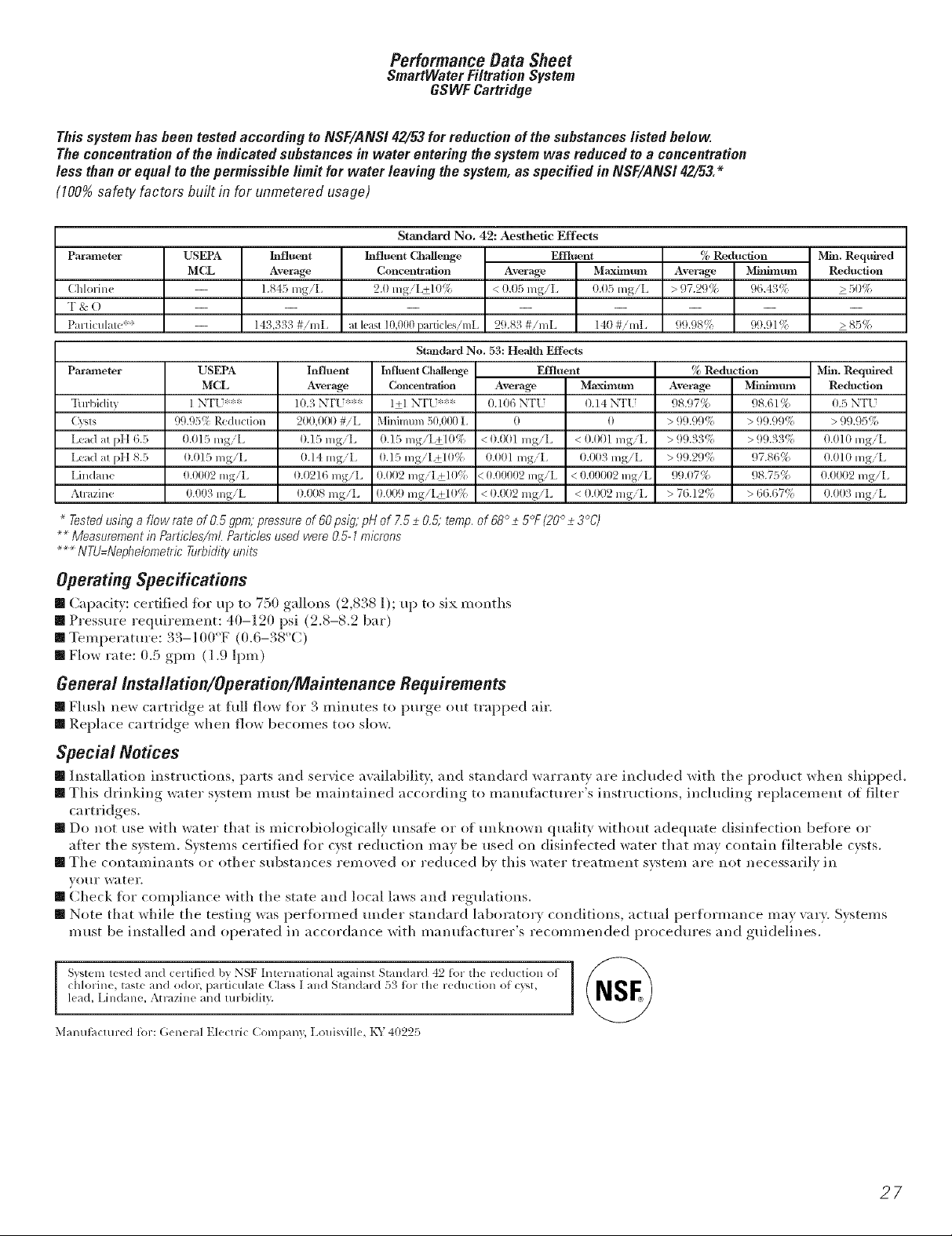
PerformanceData Sheet
SmartWater Filtration System
GSWF Cartridge
This systemhasbeen testedaccordingtoNSF/ANS142/53forreductionofthe substances listed below
Theconcentrationoftheindicatedsubstancesin water entering thesystemwas reducedto a concentration
less thanorequal tothepermissiblelimit for water leavingthesystem, as specified in NSF/ANS/42_3.*
(100%safety factors built in for unmetered usage)
Standard No. 42: Aesthetic Effects
Pa]l-al_leter
(:hlorine
"I & ()
]:'arli( ulale**
Parameter
Turbidity
(Xqs
Le_d at pH 6.5
Le_d at pH 8.5
Lindane
Atrazine
Testedusinga flow rateof O.5gpm;pressureof 6Opsig pHof 7.5_+0,5;temp,0f68°_+5°F(20°_+3°C1
.....Measurementin Particles/m/.Particlesusedwere0,5-1microns
NTU=NephelometricTurbidityunits
USEPA
MCL
USEPA
MCL
1 NT[ ***
99.95_ Reduction
0.015 lngiL
(1.015 mg/L
0.0002 lngit
0.003 mgiL
lnfluent
Average
1.845 mgiL
143,333#imL
lnfluent
Average
10.3 NT[ **"
200,000 #iL
0.15 lngiL
(1.14 lngiL
(1.0216 rag/L
0.008 mg/L
[_ffluent Challenge
Collcentr;t|iOll
2.0 lngiL+10%
al leat 10J)00 pardcles/rnL
Stmldard No. 5.'4: Health Effects
[nfluent ChMlenge Effluent
Concellh_d|ioil
l+l NT[ **"
0.10G N'[-[
Minimum50,000L
0.15 mg/L+10%
0.15 lng/L+10%
0.002 mgiL+l()!'_
0.009 mgiL+l(l%
< (}.01}1 lng/L
(}.(}0l mgiL
<0.00002 mgiL
< 0.002 lngiL
Effluent
Average Maximtan
< 0.05 mgiL tl.tl5mg/L
29.83 #/mE 140 #/mE
Average
0
Maxim(ml
0.14 NT[
0
< 0.00l lngiL
0.003 mg/L
< 0.00002 mgiL
< 0.002 lngiL
% Reduction
Average Mi_mntan
> 97.29% 96.43%
99.98!', 99.91 ¢;,
_, Reduction
Average
98.97%
> 99.9971
> 11q.3371
> 99.29!'1
99.(}7%
> 76.12_:;
Min. Reqtdred
Reduction
> 50%
>85%
Min. Req_red
Mi_immn Reduction
98.61% 0.5 NT[
> 99.9{E:; > 99.9571
>99.3'3_:; 0.01(1 lngiL
97.86% 0.010 lngiL
98.75% 0.0002 mgiL
> 66.67(:i 0.003 lngiL
Operating Specifications
[] Caparity: (ertified fin" up to 750 gallons (2,838 l); up to six months
[] Pressure requirement: 40-120 psi (2.8-8.2 bar)
[] Temperature: 33-100°F (0.6-38°(:)
[] Flow rate: 0.5 gpm (1.9 lpm)
General/nstallation/Operetion/Maintenance Requirements
[] Flush ne_,_ cartridge at hdl flow for 3 minutes to l)m'ge, out trapped air.
[] Replace cartridge when flow becomes too slow.
Special Notices
[] Installation instru(tions, parts and service awfilability, and standm'd win'rarity are included with the product when shipI)ed.
[] This drinking water s}:stem must be maintained according to manufilcturer's instructions, including replacement of filter
cartridges.
[] Do not use with water that is microbiologically unsate or of unknown quality without adequate disinfection beflwe or
aiter the system. Systems certified fl)r cyst reduction may be used on disinlected water that may contain filterable cysts.
[] The contaminants or other substances removed or reduced by this water treatment system are not necessarily in
Vo/Ir water.
[] Check fin" compliance with the state and local laws and regulations.
[] Note that while the testing was perflwmed trader standard laboratm y conditions, actual performance may w_ry. Systems
must be installed and operated in accordance with manufhcturer's recommended procedm'es and guidelines.
Svsteln lest((1 all<] c(rtifi((1 by NSF International agaillSl Standard 42 for th( r((luction of
chlorin(, tast( an(1 odor, particular( Class ] a (1 S a M, d :)_ for the re(luclion of" (:}'st,
lead, Lindane, Atrazine and mrbidily.
Malltlt}l(:ltll-e(l t()1-: (;elleral Elecu-i( (]Ollll)all}, Ixmisville, K%_ 40225
27
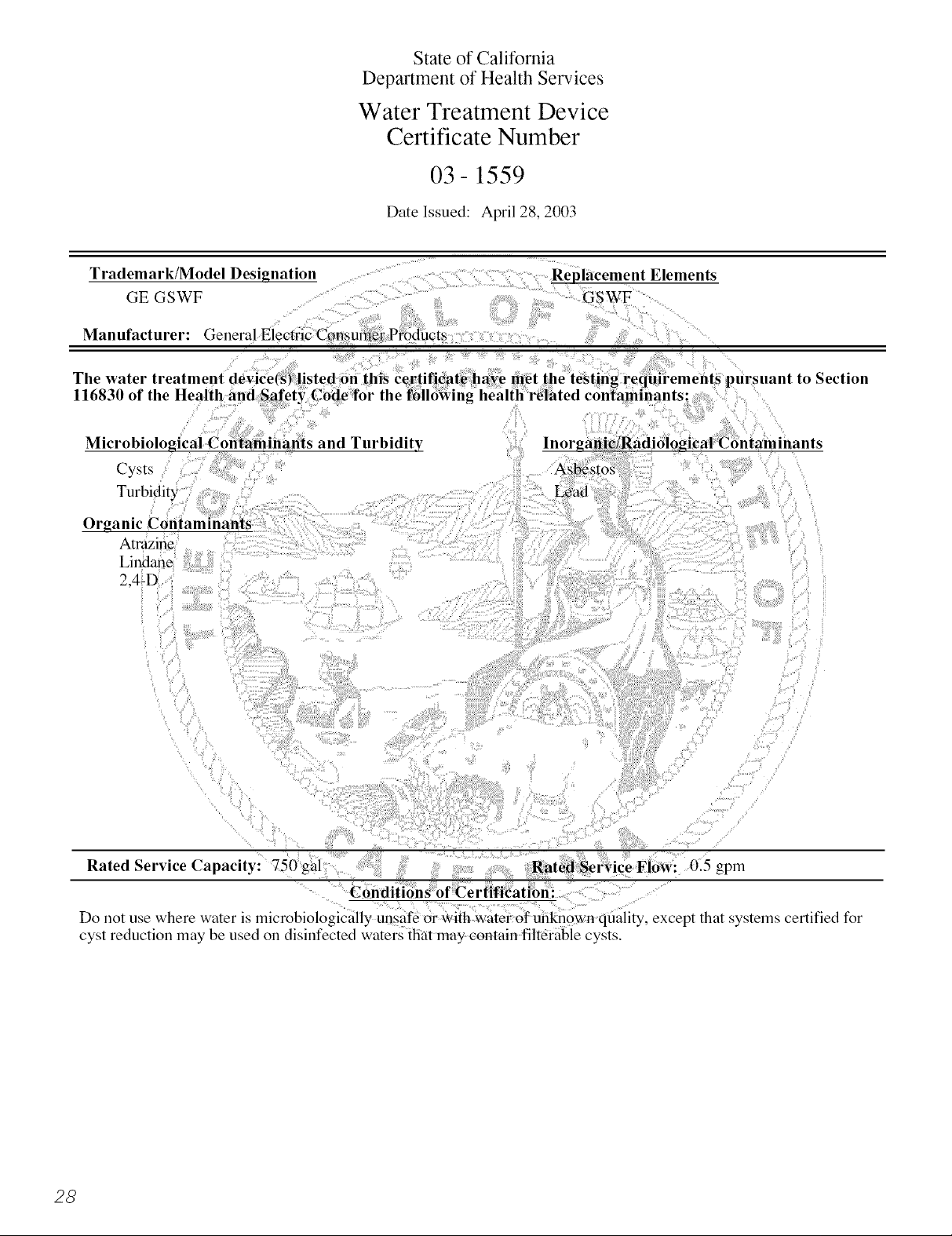
State of California
Department of Health Services
Water Treatment Device
Certificate Number
03-1559
Date Issued: April 28, 2003
to Section
Microbiological Contaminants and Turbidity
Cysts
Turbidity
Organic Contaminants
Atrazine
Lindane
2,4-D
Rated Service Capacity: 750 gal Rated Service Flow: 0.5 gpm
Conditions of Certlficatlon:
lnorganiclRadiological Contaminants
Do not use where water is microbiologically unsafe Or with water of unknown quality, except that systems certified for
cyst reduction may be used on disinfected waters that may contain filterable cysts.
28
 Loading...