

GE JKP90BM1BB, JKP90BM2BB, JKP90CM1CC, JKP90CM2CC, JKP90SM1SS Installation Guide
...
Built-In Wall Oven
with Microwave
27" (68.6 cm) model
Ilnstallat!on
nstruct=ons
If you have questions, call 1.800.GE.CARES or visit our website at:
ge.com
JKP90
30" (76.2 cm) models
JTP90, PT970
Before You Begin
Read these instructions carefully and completely.
• IMPORTANT-save these
instructions for local inspector's use.
• IMPORTANT-observe all
governing codes and ordinances.
• Note to Installer--Be sure to leave these
instructions with the consumer.
• Note to Consumer--Keep these
instructions for future reference.
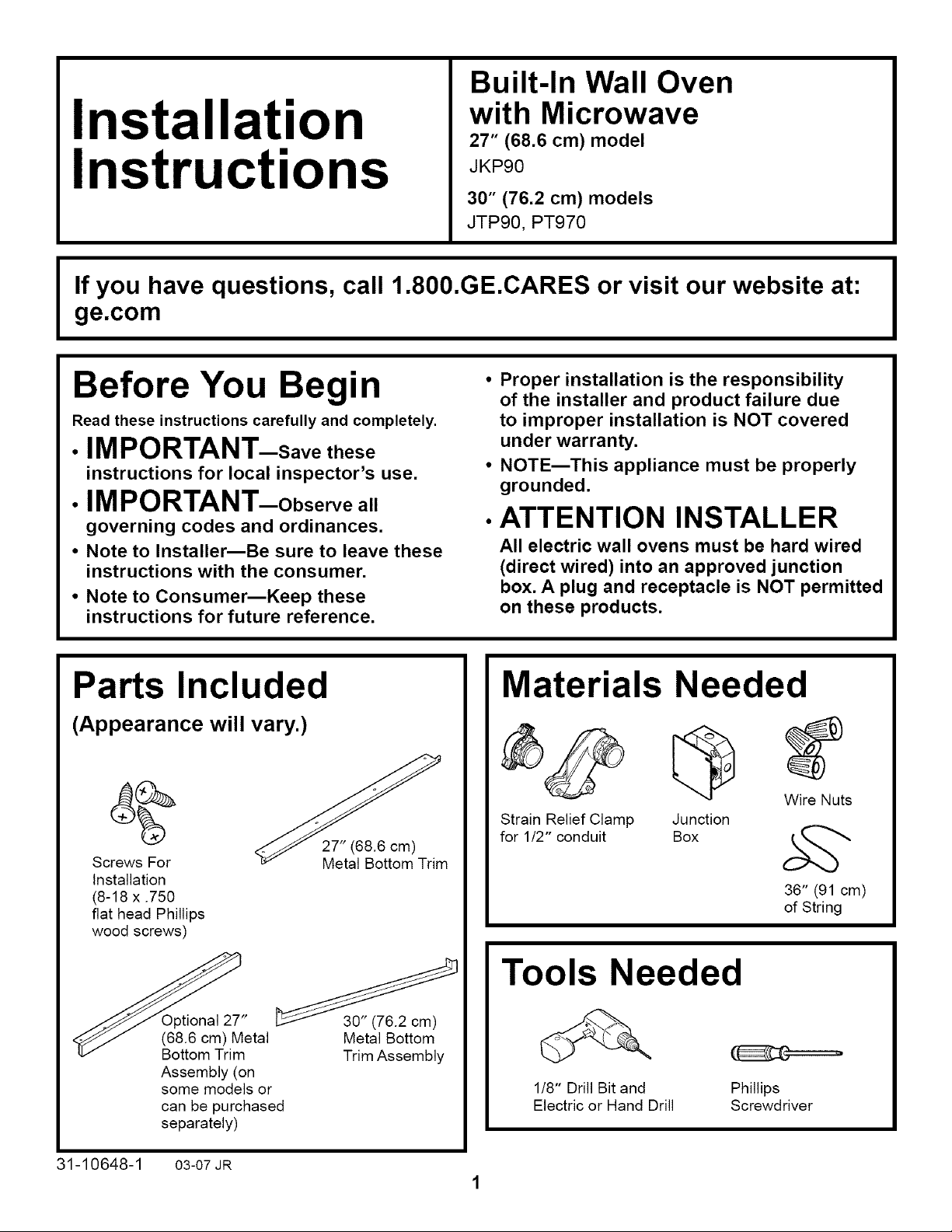
Parts Included
(Appearance will vary.)
Screws For
Installation
(8-18 x .750
fiat head Phillips
wood screws)
27" (68.6 cm)
Metal Bottom Trim
• Proper installation is the responsibility
of the installer and product failure due
to improper installation is NOT covered
under warranty.
• NOTE--This appliance must be properly
grounded.
•ATTENTION INSTALLER
All electric wall ovens must be hard wired
(direct wired) into an approved junction
box. A plug and receptacle is NOT permitted
on these products.
Materials Needed
Wire Nuts
Strain Relief Clamp Junction
for 1/2" conduit Box
36" (91 cm)
of String
31-10648-1
Optional 27"
(68.6 cm) Metal
Bottom Trim
Assembly (on
some models or
can be purchased
separately)
03-07 JR
30" (76.2 cm)
Metal Bottom
Trim Assembly
Tools Needed
1/8" Drill Bit and
Electric or Hand Drill
Phillips
Screwdriver
Installation Instructions
IMPORTANT SAFETY INSTRUCTIONS
For Your Safety
• Be sure your oven is installed properly by
a qualified installer or service technician.
• Be sure the oven is securely installed in a
cabinet that is firmly attached to the house
structure. Weight on the oven door could
cause the oven to tip and result in injury.
Never allow anyone to climb, sit, stand or
hang on the oven door.
• Make sure the cabinets and wall
coverings around the oven can withstand
the temperatures (up to 200°F [93.3°C])
generated by the oven.
WARNING: The electrical
power to the oven supply line
must be shut off while line
connections are being made. Failure
to do so could result in serious injury
or death.
Electrical
Requirements
This appliance must be supplied with the proper
voltage and frequency, and connected to an
individual, properly grounded branch circuit,
protected by a circuit breaker or fuse. See the
rating plate located on the oven frame to determine
the rating of the product. Use the chart below to
determine the minimum recommended dedicated
circuit protection.
Recommended
KW Rating KW Rating Circuit Size
240V 208V (Dedicated)
<4.8 KW <4.1 KW 20 Amp
4.9 KW-7.2 KW 4.3 KW-6.2 KW 30 Amp
7.3 KW-9.6 KW 6.3 KW-8.3 KW 40 Amp
9.7 KW-12.0 KW 8.4 KW-10.4 KW 50Amp
Electrical
Requirements (cont.)
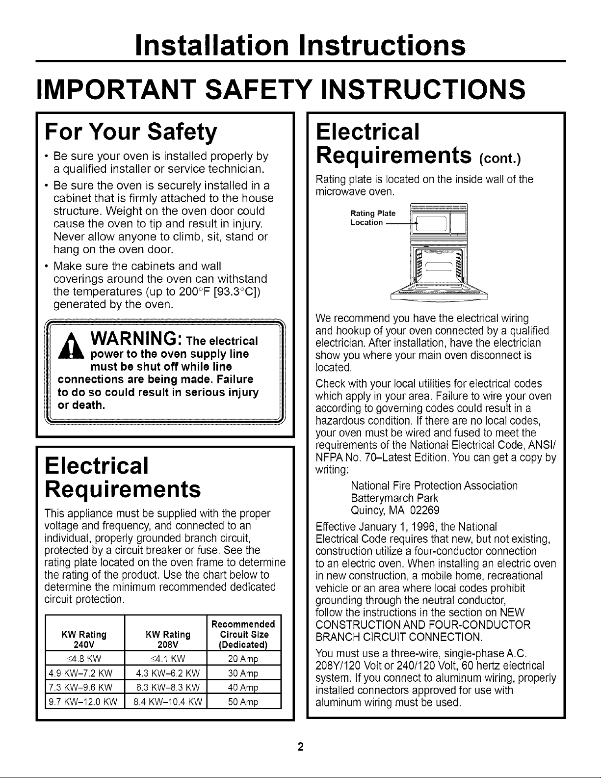
Rating plate is located on the inside watt of the
microwave oven.
LR°atiantlg'°Pnlate __
We recommend you have the electrical wiring
and hookup of your oven connected by a qualified
electrician. After installation, have the electrician
show you where your main oven disconnect is
located.
Check with your local utilities for electrical codes
which apply in your area. Failure to wire your oven
according to governing codes could result in a
hazardous condition. If there are no local codes,
your oven must be wired and fused to meet the
requirements of the National Electrical Code, ANSI/
NFPA No. 70-Latest Edition. You can get a copy by
writing:
National Fire Protection Association
Batterymarch Park
Quincy, MA 02269
Effective January 1, 1996, the National
Electrical Code requires that new, but not existing,
construction utilize a four-conductor connection
to an electric oven. When installing an electric oven
in new construction, a mobile home, recreational
vehicle or an area where local codes prohibit
grounding through the neutral conductor,
follow the instructions in the section on NEW
CONSTRUCTION AND FOUR-CONDUCTOR
BRANCH CIRCUIT CONNECTION.
You must use a three-wire, single-phase A.C.
208Y/120 Volt or 240/120 Volt, 60 hertz electrical
system. If you connect to aluminum wiring, properly
installed connectors approved for use with
aluminum wiring must be used.

Installation Instructions
Pre-lnstallation Checklist
Remove packaging materials. Check
inside microwave, behind hinges and
under false bottom. Remove labels on
the outside of the door, plastic on trims
and panel, all tape around the oven like
and any shipping screws securing the
oven to the base pad.
Oven Racks
Literature
Pack
Door removal is not a requirement for
installation of the product, but is an
added convenience. To remove the door:
Open the oven door as far as it will go.
Push both hinge Hinge
locks down toward _ft _ Position
the door frame, Hinge/_/*_
to the unlocked slot _,_.d
position. This may
require a flat blade
screwdriver.
DO NOT LIFT THE DOOR
BY THE HANDLE!
Place hands on both sides of "F"f,.-_
the door, and close the oven I1_
door to the removal position, I1_/ fJ
which is most of the way closed. Ildl /
_.._b,= Unlocked
Hinge
Arm
i]
Open oven door and remove literature
pack and oven racks. Open microwave
door and remove shelves and turntable
package.
Remove Installation Instructions
from literature pack and read them
carefully before you begin.
Be sure to place all literature,
Owner's Manual, Installations, etc.
in a safe place for future reference.
out until the
hinge arms
clear the slots.
Lift door up and _!
Hinge Clears Slot
NOTE: The oven door is very heavy.
Be sure you have a firm grip before lifting
the oven door off the hinges. Use caution
once the door is removed. Do not lay the
door on its handle. This could cause dents
or scratches.
Place the oven on a table or platform even
with the cutout opening. (Platform must
support 255 Ibs. [115 Kg].)
Remove the bottom trim from the top
of the oven. It will be installed at the end
of the installation process. The trim is
wrapped separately and taped to the
top of the unit.
3
Installation Instructions
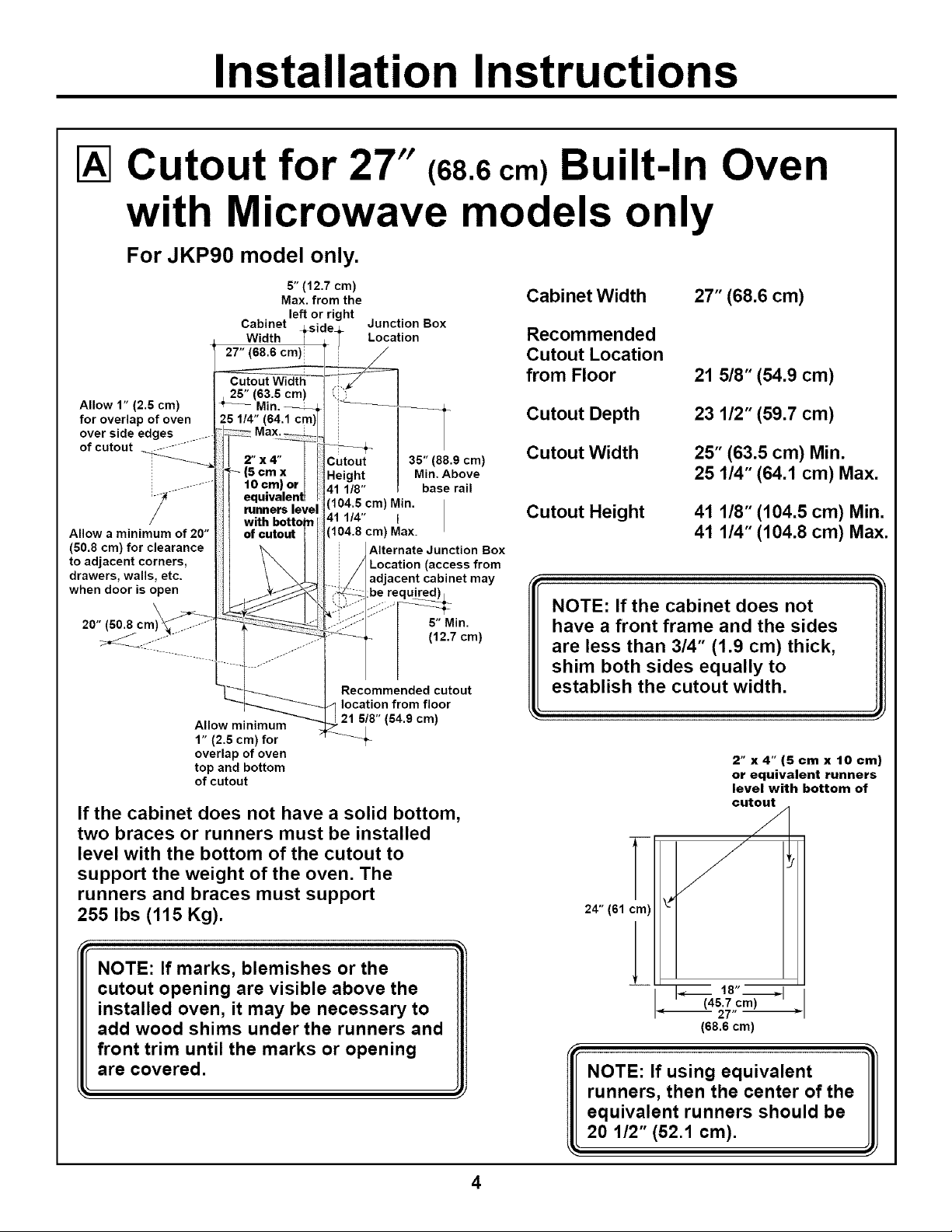
IA1Cutout for 27" (68.6cm) Built-In Oven
with Microwave models only
For JKP90 model only.
5" (12.7 cm)
Max.fromthe Cabinet Width 27" (68.6 cm)
Cabinet Junction Box
left or right
Width Location Recommended
Cutout Location
from Floor 21 5/8" (54.9 cm)
Allow 1" (2,5 cm)
for overlap of oven
over side edges ....
of cutout ............
Allow a minimum of 20"
(50.8 cm) for clearance
to adjacent corners,
drawers, walls, etc.
when door is open
eq (104,5 cm) Min.
runners level
Cutout 35" (88.9 cm)
Height Min, Above
41 1/8" base rail
41 1/4" I
(104.8 cm) Max.
Alternate Junction Box
Location (access from
adjacent cabinet may
:be
\
20" (80.8 cm)
Recommended cutout
location from floor
Allow minimum
1" (2.5 cm) for
overlap of oven
top and bottom
of cutout
6/8" (54.9 cm)
4-
If the cabinet does not have a solid bottom,
two braces or runners must be installed
level with the bottom of the cutout to
support the weight of the oven. The
runners and braces must support
255 Ibs (115 Kg).
6" Min.
(12.7 cm)
Cutout Depth
Cutout Width
23 1/2" (59.7 cm)
25" (63.5 cm) Min.
25 1/4" (64.1 cm) Max.
Cutout Height
41 1/8" (104.5 cm) Min.
41 1/4" (104.8 cm) Max.
NOTE: If the cabinet does not
have a front frame and the sides
are less than 3/4" (1.9 cm) thick,
shim both sides equally to
establish the cutout width.
2"x4"(Scmx 10cm)
or equivalent runners
level with bottom of
cutout
24" (61 cm)
NOTE: If marks, blemishes or the
cutout opening are visible above the
installed oven, it may be necessary to
add wood shims under the runners and
front trim until the marks or opening
are covered.
-- _ 18",--_1
(45.7 cm)
27"
(68.6 cm)
NOTE: If using equivalent
runners, then the center of the
equivalent runners should be
20 1/2" (52,1 cm),
= =
4
 Loading...